hydraulic bottle jack - ferval · 2017-07-06 · hydraulic bottle jack read, study and understand...
TRANSCRIPT
HYDRAULIC BOTTLE JACK
Read, study and understand all warnings and operating instructions prior to use.Do not overload this jack beyond the rated capacity.This jack is designed for use only on hard level surfaces capable of sustaining the load.This is a lifting device only, immediately after lifting, support the vehicle with jack stands.Do not get under or allow anyone under the vehicle until it has been supported by jack stands.Lift only on areas of the vehicle as specified by the vehicle manufacturer.Center load on saddle prior to lifting.Some vehicles require an adapter to properly engage the frame for lifting. use vehicle manufacturers instructions on proper lifting.No alterations to the jack shall be made. Only attachments, restraints, or adapters supplied by the manufacturer shall be used.Failure to heed these warnings may result in personal injury and/or property damage.
1.
2.3.
4.
5.
6.
7.8.
9.10.
11.
INSTRUCTIONS FOR USE
POSSIBLE PROBLEMS AND SOLUTIONS TEST CERTIFICATE
MAIN TECHNICAL DATA
MAINTENANCE
PURGING AIL FROM HYDRAULIC SYSTEM
RUST PREVENTION
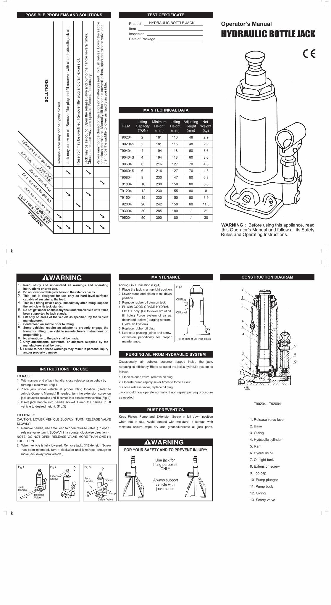
CONSTRUCTION DIAGRAM
TO RAISE:1. With narrow end of jack handle, close release valve tightly by turning it clockwise. (Fig.1)2. Place jack under vehicle at proper lifting location. (Refer to vehicle Owner’s Manual.) If needed, turn the extension screw on jack counterclockwise until it comes into contact with vehicle.(Fig.2)3. Insert jack handle into handle socket. Pump the handle to lift vehicle to desired height. (Fig.3)
TO LOWER:CAUTION: LOWER VEHICLE SLOWLY! TURN RELEASE VALVE SLOWLY!1. Remove handle, use small end to open release valve. (To open release valve turn it SLOWLY in a counter clockwise direction.)NOTE: DO NOT OPEN RELEASE VALVE MORE THAN ONE (1) FULL TURN2. When vehicle is fully lowered. Remove jack. (If Extension Screw has been extended, turn it clockwise until it retracts enough to move jack away from vehicle.)
Occasionally, air bubbles become trapped inside the jack,reducing its efficiency. Bleed air out of the jack’s hydraulic system as follows:1. Open release valve, remove oil plug.2. Operate pump rapidly sever times to force air out.3. Close release valve, replace oil plug.Jack should now operate normally. If not, repeat purging procedureas needed.
Keep Piston, Pump and Extension Screw in full down positionwhen not in use. Avoid contact with moisture. If contact with moisture occurs, wipe dry and grease/lubricate all jack parts.
Adding Oil/ Lubrication (Fig.4)1. Place the jack in an upright position.2. Lower pump and piston to full down position.3. Remove rubber oil plug on jack.4. Fill with GOOD GRADE HYDRAU- LIC OIL only. (Fill to lower rim of oil fill hole.) Purge system of air as described below ( purging air from Hydraulic System).5. Replace rubber oil plug.6. Lubricate pivoting joints and screw extension periodically for proper maintenance.
Fig.1 Fig.2 Fig.3
Fig.4
Oil Plug
Oil Level
(Fill to Rim of Oil Plug Hole)
Jack Handle
Jack Handle
ReleaseValve
ExtensionScrew
Pump
Safety Valve
Socket
FOR YOUR SAFETY AND TO PREVENT INJURY:
Always supportvehicle with jack stands.
Use jack for lifting purposes
ONLY.
T90204 - T92004
1. Release valve lever
2. Base
3. O-ring
4. Hydraulic cylinder
5. Ram
6. Hydraulic oil
7. Oil-tight tank
8. Extension screw
9. Top cap
10. Pump plunger
11. Pump body
12. O-ring
13. Safety valve
Rel
ease
val
ve m
ay n
ot b
e tig
htly
clo
sed.
Jack
will
not li
ft loa
d or fu
ll
rated
capa
city
Jack
lowers
unde
r load
Oil lea
king f
rom fil
ler pl
ug
Pump f
eels
spon
gy
Handle
raise
s or fl
ies ba
ck
unde
r load Ja
ck w
ill no
t lift f
ull he
ight
Jack
may
be
low
on
oil.
Rem
ove
fille
r plu
g an
d fil
l res
ervo
ir w
ith c
lean
hyd
raul
ic ja
ck o
il.
Res
ervo
ir m
ay b
e ov
erfil
led.
Rem
ove
fille
r plu
g an
d dr
ain
exce
ss o
il.
Jack
may
be
air-
boun
d. O
pen
the
rele
ase
valv
e an
d pu
mp
the
hand
le s
ever
al ti
mes
.C
lose
the
rele
ase
valv
e an
d op
erat
e. R
epea
t if n
eces
sary
.
Valv
es m
ay n
ot b
e cl
osed
or h
ave
fore
ign
mat
ter p
rese
nt. T
o flu
sh v
alve
s. L
ower
the
sadd
le
and
clos
e th
e re
leas
e. M
anua
lly li
ft th
e sa
ddle
sev
eral
inch
es, o
pen
the
rele
ase
valv
e an
dth
en fo
rce
the
sadd
le to
low
er a
s ra
pidl
y as
pos
sibl
e.
POSSIBLE
SOLU
TIO
NS
ProductItemInspectorDate of Package
HYDRAULIC BOTTLE JACK
ITEMLifting
Capacity(TON)
MinimumHeight(mm)
LiftingHeight(mm)
AdjustingHeight(mm)
Net Weight
(kg)
T90204
T90204S
T90404
T90404S
T90604
T90604S
T90804
T91004
T91204
T91504
T92004
T93004
T95004
2
2
4
4
6
6
8
10
12
15
20
30
50
181
181
194
194
216
216
230
230
230
230
242
285
300
116
116
118
118
127
127
147
150
155
150
150
180
180
48
48
60
60
70
70
80
80
80
80
60
/
/
2.9
2.9
3.6
3.6
4.8
4.8
6.3
6.8
8
8.9
11.5
21
30