hy-bon engineering company - global methane initiative · 5 still vent non condensible (at well...
TRANSCRIPT

Hy-bon Engineering Company

Reducing Methane Emissions with
Vapor Recovery on Storage Tanks


Vapor Recovery Units: Agenda
• Methane Losses
• Methane Savings
• Is Recovery Profitable?
• Industry Experience
• Discussion Questions

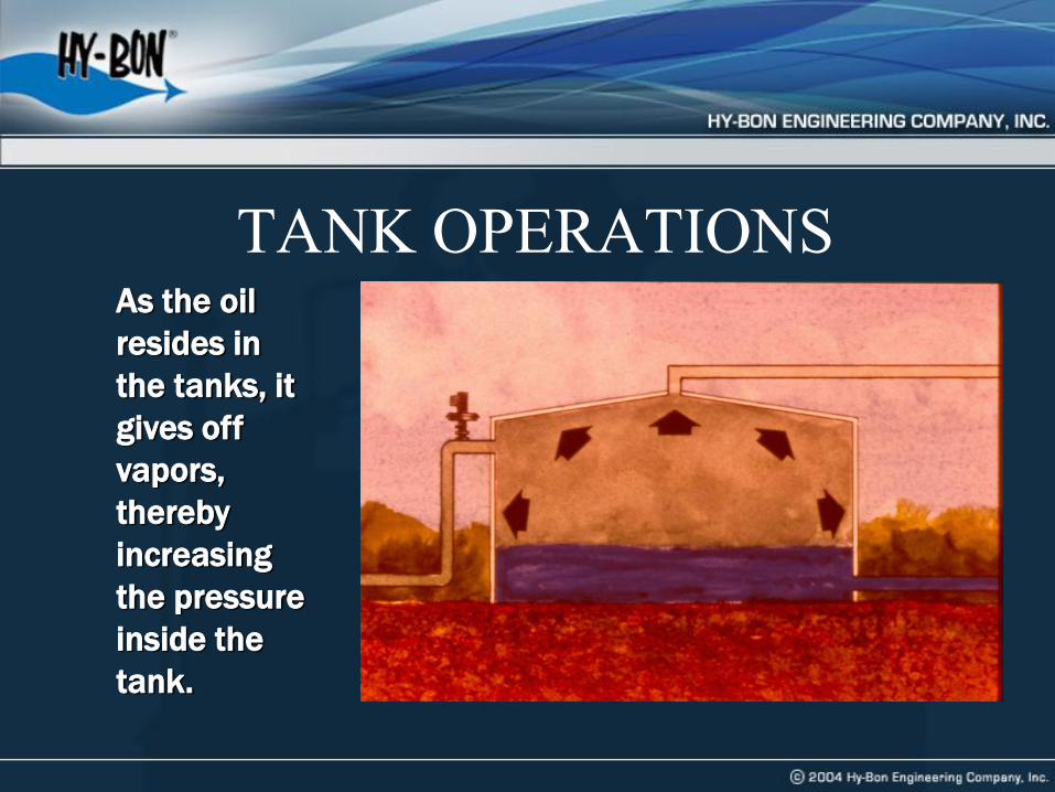
TANK OPERATIONS As the oil
resides in
the tanks, it
gives off
vapors,
thereby
increasing
the pressure
inside the
tank.


Sources of Methane Losses from Tanks • A storage tank battery can vent 5 to 500 mcf of natural gas and
light hydrocarbon vapors to the atmosphere each day – Vapor losses are primarily a function of oil or condensate throughput,
gravity, and gas-oil separator pressure
• Flash losses – Occur when crude oil or condensate is transferred from a gas-oil
separator at higher pressure to a storage tank at atmospheric pressure
• Working losses – Occur when crude or condensate levels change
• Standing losses – Occur with daily and seasonal temperature and barometric pressure
changes
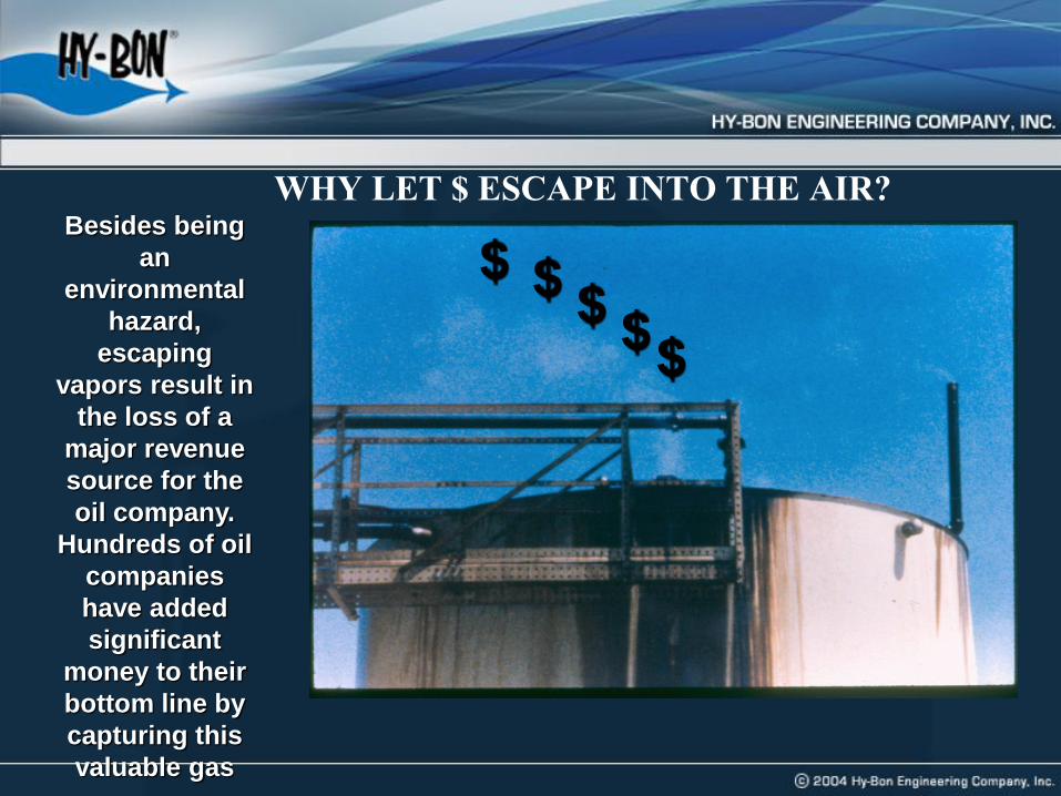
WHY LET $ ESCAPE INTO THE AIR? Besides being
an
environmental
hazard,
escaping
vapors result in
the loss of a
major revenue
source for the
oil company.
Hundreds of oil
companies
have added
significant
money to their
bottom line by
capturing this
valuable gas
stream.
$
$ $ $
$


Methane Savings:
Vapor Recovery • Vapor recovery can capture up to 95% of hydrocarbon
vapors from tanks
• Recovered vapors have higher heat content than pipeline
quality natural gas
• Recovered vapors are more valuable than natural gas
and have multiple uses
– Re-inject into sales pipeline
– Use as on-site fuel
– Send to processing plants for recovering valuable
natural gas liquids
Types of Vapor Recovery Units • Conventional vapor recovery units (VRUs)
– Use special designed packages configured to capture
low pressure, wet gas streams with no oxygen ingress
– Use rotary screw or rotary vane compressor for wet gas
– Scroll compressors are new to this market & also work well
– Require electrical power or engine driver
• Venturi ejector vapor recovery units (EVRUTM) or Vapor Jet
– Use Venturi jet ejectors in place of rotary compressors
– Contain no moving parts
– EVRUTM requires a source of high pressure motive gas and intermediate
pressure discharge system
– Vapor Jet requires volume of produced water

VAPOR RECOVERY SYSTEMS

Conventional Vapor Recovery Unit
Crude Oil
Stock
Tank(s)
Control
Pilot
Vent Line
Back Pressure Valve
Suction
Scrubber
Suction
Line
Condensate
Return
Bypass
Valve
Electric
Control
Panel
Electric Driven
Rotary Compressor
Gas Sales
Meter Run
Gas
Liquid
Transfer Pump
Check Valve
Source: Evans & Nelson (1968)
Sales
15
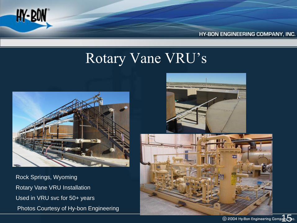
Rotary Vane VRU’s
Rock Springs, Wyoming
Rotary Vane VRU Installation
Used in VRU svc for 50+ years
Photos Courtesy of Hy-bon Engineering

Eni installed vapor recovery systems in their Dacion East and West facilities in Venezuela, each designed to move 1.4 MMSCFD of
gas at pressures to 230 psig.
Eni Oil & GasDacion Field,
Venezuela; 2004
Rotary Screws used in VRU Svc
for 15+ years
Rotary Screw VRU’s

• Rotary Screw Vapor recovery units were installed to capture
up to 1.4 MMCFD per site
• White paper was written shortly after installation on the
economic success of the project; denoting economic payback
of less than 12 months
• A highly valuable 70 API gravity condensate was recovered
from the gas stream and used to blend with the primary low
API gravity oil production – at an approximate daily rate of
100 to 150 barrels of condensate per unit.
Project Overview – Eni Dacion (Venezuela)

18
Vapor Jet System
*Patented by Hy-Bon Engineering

Vapor Jet System*
*Patented by Hy-Bon Engineering
• Utilizes produced water in closed loop system to effect gas gathering from tanks
• Small centrifugal pump forces water into Venturi jet, creating vacuum effect
• Limited to gas volumes of 77 Mcf/day and discharge pressure of 40 psig

Quantify Volume of Losses
• Estimate losses from chart based on oil characteristics,
pressure, and temperature at each location (± 50%)
• Estimate emissions using the E&P Tank Model (± 20%)
• Engineering Equations – Vasquez Beggs (± 20%)
• Measure losses using recording manometer, turbine meter
or ultrasonic meter over several cycles (± 5%)
– This is the best approach for facility design

Estimated Volume of Tank Vapors
Pressure of Vessel Dumping to Tank (psig)
Vap
or
Ven
ted
fro
m T
ank
s,
Cu
bic
fo
ot
/ bar
rel
Gas
/Oil
Rat
io
110
100
90
80
70
60
50
40
30
10
20
10 20 30 40 50 60 70 80
o API = API gravity
AP
I
Gra
vitie
s


What is the Recovered Gas Worth? • Value depends on heat content of gas
• Value depends on how gas is used
– On-site fuel
• Valued in terms of fuel that is replaced
– Natural gas pipeline
• Measured by the higher price for rich (higher heat content) gas
– Gas processing plant
• Measured by value of natural gas liquids and methane, which can be
separated
• Gross revenue per year = (Q x P x 365) + NGL
– Q = Rate of vapor recovery (MMBtu per day)
– P = Price of natural gas (US$/MMBtu)
– NGL = Value of natural gas liquids

Value of Natural Gas Liquids
1 – Natural Gas price assumed at Mexico’s cost US$5/MMBtu
2 – Prices of Individual NGL components estimated based on natural gas price in Mexico.
NGL Components
1 Btu/gal
2 MMBtu/gal
3 US$/gal
4 US$/MMBtu1,2
(=3/2)
Methane 59,755 0.060 0.30 5.00
Ethane 74,010 0.074 0.26 3.45
Propane 91,740 0.092 045 5.09
n Butane 103,787 0.104 0.49 4.91
iso Butane 100,176 0.100 0.53 5.44
Pentanes+ 105,000 0.105 0.57 5.27
5
Btu/cf
6
MMBtu/Mcf
7
US$/Mcf
(=4*6)
8
US$/MMBtu
9
Vapor
Composition
10
Mixture
(MMBtu/Mcf)
11
Value
(US$/Mcf)
(=8*10)
Methane 1,000 1.000 $5.00 $5.00 82% 0.82 $4.10
Ethane 1,773 1.773 $6.12 $3.45 8% 0.14 $0.49
Propane 2,524 2.524 $12.86 $5.,09 4% 0.10 $0.51
n Butane 3,271 3.271 $16.05 $4.91 3% 0.10 $0.48
iso Butane 3,261 3.261 $17.74 $5.44 1% 0.03 $0.18
Pentanes+ 4,380 4.380 $23.06 $5.27 2% 0.09 $0.46
Total 1.28 6.22

Is Recovery Profitable? Financial Analysis for a Conventional VRU Project
Peak
Capacity
(Mcf/day)
Installation
& Capital
Costs1
(US$)
O&M
Costs
(US$/year)
Value of
Gas2
(US$/year)
Annual
Savings
(US$)
Simple
Payback
(months)
Internal
Rate of
Return %
25 35,738 7,367 28,398 21,031 20 51
50 46,073 8,419 56,795 48,376 11 102
100 55,524 10,103 113,590 103,487 6 185
200 74,425 11,787 227,181 215,394 4 289
500 103,959 16,839 567,952 551,113 2 530
1 - Unit cost plus estimated installation of 75% of unit cost
2 - US$6.22 x ½ peak capacity x 365, Assumed price includes enriched gas

Industry Experience:
EnCana Oil & Gas
• Vapor recovery unit installed in Frenchie Draw, WY, U.S.
• Captures vapors from
– Separators
– Crude oil storage tank
– Non-condensable dehydrator still gas
• VRU designed to handle 500 Mcf/day
– Additional capacity over the estimated 284 Mcf/day of total
gas from all emission sources

• Quantify the volume of vapor emissions
OIL
OIL
200 PSIG
125 PSIG
40 PSIG
OIL
1
2
3
4 5
ATM ATM
GAS
GAS GAS
ATM SUCTION
125 PSIG DISCHARGE
1 FLASH LOSS (125 PSIG - ATM PSIG)
2 FLASH LOSS (200 PSIG - ATM PSIG)
3 FLASH LOSS (40 PSIG – ATM)
4 WORKING & BREATHING LOSS
5 STILL VENT NON CONDENSIBLE
(AT WELL LOCATION)
GAS
Total Emissions-
284 MSCFD
Source: EnCana Oil & Gas (USA) Inc.

EnCana Oil & Gas:
Project Costs • Determine the cost of VRU project
Installation (US$)
VRU Unit (500 Mcfd) - 90,000
Generator- 85,000
Vent Header- 25,000
Labor- 200,000
TOTAL 400,000
O & M (US$)
VRU Unit (500 Mcfd) - 15,000
Generator- 18,000
Fuel- 73,000
TOTAL 106,000

EnCana Oil & Gas:
Project Economics • Evaluate VRU economics
Capacity– 500 Mcfd
Installation Cost - US$400,000
O&M- US$106,000/year
Value of Gas*- US$515,594/year
*Conservatively based on natural gas price assumed to be US$5/MMBtu
and 1 Mcf = 1 MMBtu
Gas Price (US$/MMBtu) 3 5 7
Payback (months) 24 12 8
NPV (US$) 281,682 973,023 1,664,364

Industry Experience: Anadarko • Vapor Recover Tower (VRT)
– Add separation vessel between heater treater or low pressure
separator and storage tanks that operates at or near atmospheric
pressure
• Operating pressure range: 1–5 psig
– Compressor (VRU) is used to capture gas from VRT
– Oil/Condensate gravity flows from VRT to storage tanks
• VRT insulates the VRU from gas surges with stock tank level
changes
• VRT more tolerant to higher and lower pressures
• Stable pressure allows better operating factor for VRU

VRT/VRU Photos
Courtesy of Anadarko
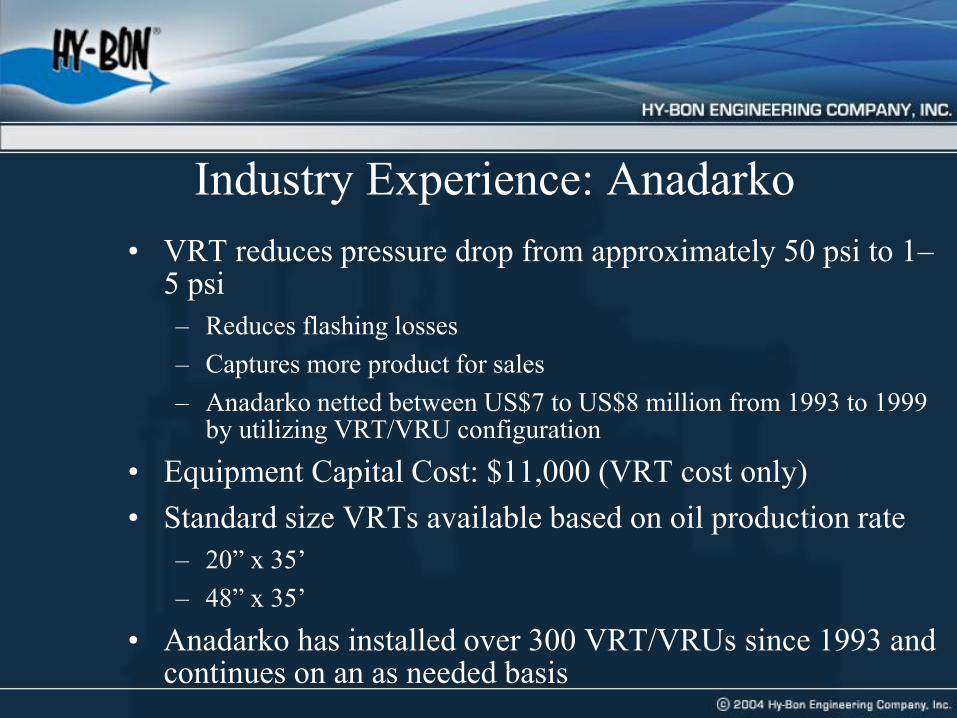
Industry Experience: Anadarko
• VRT reduces pressure drop from approximately 50 psi to 1–5 psi
– Reduces flashing losses
– Captures more product for sales
– Anadarko netted between US$7 to US$8 million from 1993 to 1999 by utilizing VRT/VRU configuration
• Equipment Capital Cost: $11,000 (VRT cost only)
• Standard size VRTs available based on oil production rate
– 20” x 35’
– 48” x 35’
• Anadarko has installed over 300 VRT/VRUs since 1993 and continues on an as needed basis

33
Industry Experience: ConocoPhillips • Vapor recovery units installed in Baker, MT
• Anticipated multiple sites, so detailed technical review of options was
conducted
• Volumes per site ranged from 30 mcfd to 350 mcfd
• Pipeline pressure ranged from 20 to 40 psig
• Captures vapors from
– Crude oil storage tanks
– Produced Water tanks
– All manifolded together in closed loop system
– Gas blanket system used to backfill tanks

34
Industry Experience: ConocoPhillips
• Evaluated rotary screw, rotary vane, vapor jet and EVRU
• Selected rotary vane VRU’s due to wide range of volumes of gas
and low discharge pressure across the sites
• Pilot project on 3 locations, then added 6 addt’l sites
• Designed for optimum gas capture
– Pressure transmitter on the tanks
– Sloping lines to the VRU
– Package specifically designed for vapor recovery service
– Automated liquid handling and bypass systems

Baker, MT ConocoPhillips VRU installation; Picture Courtesy of Hy-bon Engineering

Baker, MT ConocoPhillips VRU installation; Picture Courtesy of Hy-bon Engineering

Baker, MT ConocoPhillips VRU installation; Picture Courtesy of Hy-bon Engineering

Baker, MT ConocoPhillips VRU installation; Picture Courtesy of Hy-bon Engineering
39
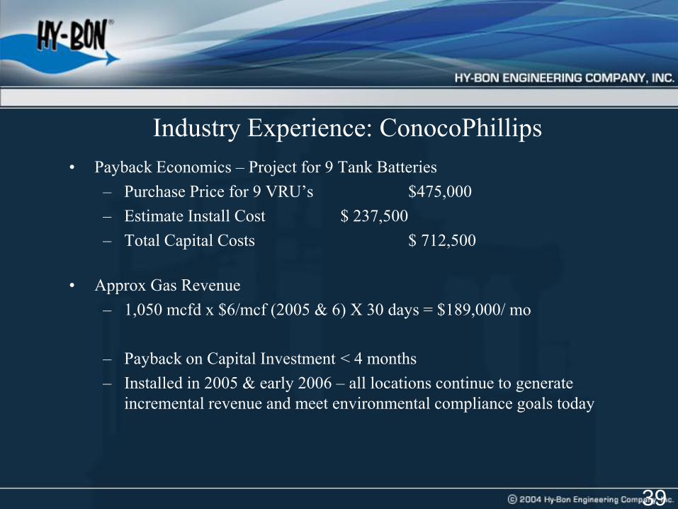
Industry Experience: ConocoPhillips
• Payback Economics – Project for 9 Tank Batteries
– Purchase Price for 9 VRU’s $475,000
– Estimate Install Cost $ 237,500
– Total Capital Costs $ 712,500
• Approx Gas Revenue
– 1,050 mcfd x $6/mcf (2005 & 6) X 30 days = $189,000/ mo
– Payback on Capital Investment < 4 months
– Installed in 2005 & early 2006 – all locations continue to generate
incremental revenue and meet environmental compliance goals today

Lessons Learned • Vapor recovery can yield generous returns when there are
market outlets for recovered gas
– Recovered high heat content gas has extra value
– Vapor recovery technology can be highly cost-effective in
most general applications
– Venturi jet models work well in certain niche applications,
with reduced operating and maintenance costs
• Potential for reduced compliance costs can be considered
when evaluating economics of VRU, EVRUTM, or Vapor Jet

Lessons Learned (continued) • VRU should be sized for maximum volume
expected from storage tanks (rule-of-thumb is to double daily average volume)
• Rotary vane, screw or scroll type compressors recommended for VRUs where Venturi ejector jet designs are not applicable
• EVRUTM recommended where there is a high pressure gas compressor with excess capacity
• Vapor Jet recommended where there is produced water, less than 75 Mcf per day gas and discharge pressures below 40 psig