hvdc transmission systems unit-1cet.edu.in/noticefiles/229_hvdc_note.pdf · 1 hvdc transmission...
TRANSCRIPT

1
HVDC Transmission Systems
UNIT-1
Introduction
Electric power transmission was originally developed with direct current. The availability
of transformers and the development and improvement of induction motors at the beginning of
the 20th century, led to the use of AC transmission.
DC Transmission now became practical when long distances were to be covered or where
cables were required. Thyristors were applied to DC transmission and solid state valves became
a reality.
With the fast development of converters (rectifiers and inverters) at higher voltages and
larger currents, DC transmission has become a major factor in the planning of the power
transmission. In the beginning all HVDC schemes used mercury arc valves, invariably single
phase in construction, in contrast to the low voltage polyphase units used for industrial
application. About 1960 control electrodes were added to silicon diodes, giving silicon-
controlled-rectifiers (SCRs or Thyristors).
Today, the highest functional DC voltage for DC transmission is +/- 600kV. D.C
transmission is now an integral part of the delivery of electricity in many countries throughout
the world.
Comparison of AC and DC Transmission
The merits of two modes of transmission (AC & DC) should be compared based on the
following factors.
1) Economics of transmission
2) Technical Performance
3) Reliability
Economics of Power Transmission:
In DC transmission, inductance and capacitance of the line has no effect on the power
transfer capability of the line and the line drop. Also, there is no leakage or charging current of
the line under steady conditions.
A DC line requires only 2 conductors whereas AC line requires 3 conductors in 3-phase
AC systems. The cost of the terminal equipment is more in DC lines than in AC line. Break-even

2
distance is one at which the cost of the two systems is the same. It is understood from the below
figure that a DC line is economical for long distances which are greater than the break-even
distance.
Figure: Relative costs of AC and DC transmission lines vs distance
Technical Performance:
Due to its fast controllability, a DC transmission has full control over transmitted power,
an ability to enhance transient and dynamic stability in associated AC networks and can limit
fault currents in the DC lines. Furthermore, DC transmission overcomes some of the following
problems associated with AC transmission.
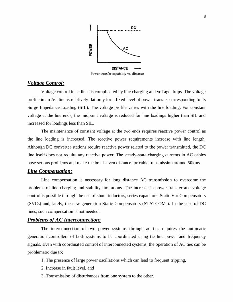
Stability Limits:
The power transfer in an AC line is dependent on the angle difference between the
voltage phasors at the two line ends. For a given power transfer level, this angle increases with
distance. The maximum power transfer is limited by the considerations of steady state and
transient stability. The power carrying capability of an AC line is inversely proportional to
transmission distance whereas the power carrying ability of DC lines is unaffected by the
distance of transmission.
3
Voltage Control:
Voltage control in ac lines is complicated by line charging and voltage drops. The voltage
profile in an AC line is relatively flat only for a fixed level of power transfer corresponding to its
Surge Impedance Loading (SIL). The voltage profile varies with the line loading. For constant
voltage at the line ends, the midpoint voltage is reduced for line loadings higher than SIL and
increased for loadings less than SIL.
The maintenance of constant voltage at the two ends requires reactive power control as
the line loading is increased. The reactive power requirements increase with line length.
Although DC converter stations require reactive power related to the power transmitted, the DC
line itself does not require any reactive power. The steady-state charging currents in AC cables
pose serious problems and make the break-even distance for cable transmission around 50kms.
Line Compensation:
Line compensation is necessary for long distance AC transmission to overcome the
problems of line charging and stability limitations. The increase in power transfer and voltage
control is possible through the use of shunt inductors, series capacitors, Static Var Compensators
(SVCs) and, lately, the new generation Static Compensators (STATCOMs). In the case of DC
lines, such compensation is not needed.
Problems of AC Interconnection:
The interconnection of two power systems through ac ties requires the automatic
generation controllers of both systems to be coordinated using tie line power and frequency
signals. Even with coordinated control of interconnected systems, the operation of AC ties can be
problematic due to:
1. The presence of large power oscillations which can lead to frequent tripping,
2. Increase in fault level, and
3. Transmission of disturbances from one system to the other.

4
The fast controllability of power flow in DC lines eliminates all of the above
problems. Furthermore, the asynchronous interconnection of two power systems can only be
achieved with the use of DC links.
Ground Impedance:
In AC transmission, the existence of ground (zero sequence) current cannot be permitted
in steady-state due to the high magnitude of ground impedance which will not only affect
efficient power transfer, but also result in telephonic interference. The ground impedance is
negligible for DC currents and a DC link can operate using one conductor with ground return
(monopolar operation).
The ground return is objectionable only when buried metallic structures (such as pipes)
are present and are subject to corrosion with DC current flow. While operating in the monopolar
mode, the AC network feeding the DC converter station operates with balanced voltages and
currents. Hence, single pole operation of dc transmission systems is possible for extended period,
while in AC transmission, single phase operation (or any unbalanced operation) is not feasible
for more than a second.
Disadvantages of DC Transmission:
The scope of application of DC transmission is limited by
1. High cost of conversion equipment.
2. Inability to use transformers to alter voltage levels.
3. Generation of harmonics.
4. Requirement of reactive power and
5. Complexity of controls.
Over the years, there have been significant advances in DC technology, which have
tried to overcome the disadvantages listed above except for (2). These are
1. Increase in the ratings of a thyristor cell that makes up a valve.
2. Modular construction of thyristor valves.
3. Twelve-pulse (and higher) operation of converters.
4. Use of forced commutation.
5. Application of digital electronics and fiber optics in the control of converters.
Reliability:

5
The reliability of DC transmission systems is good and comparable to that of AC
systems. The reliability of DC links has also been very good.
There are two measures of overall system reliability-energy availability and transient
reliability.
Energy availability:
Energy availability = 100 (1 – equivalent outage time) %
Actual time
Where equivalent outage time is the product of the actual outage time and the fraction of
system capacity lost due to outage.
Transient reliability:
This is a factor specifying the performance of HVDC systems during recordable faults on
the associated AC systems.
Transient reliability = 100 X No. of times HVDC systems performed as designed
No. of recordable AC faults
Recordable AC system faults are those faults which cause one or more AC bus phase
voltages to drop below 90% of the voltage prior to the fault.
Both energy availability and transient reliability of existing DC systems with thyristor
valves is 95% or more.
Application of DC Transmission
Due to their costs and special nature, most applications of DC transmission generally fall
into one of the following three categories.
Underground or underwater cables:
In the case of long cable connections over the breakeven distance of about 40-50 km, DC
cable transmission system has a marked advantage over AC cable connections. Examples of this
type of applications were the Gotland (1954) and Sardinia (1967) schemes. The recent
development of Voltage Source Converters (VSC) and the use of rugged polymer DC cables,
with the so-called “HVDC Light” option, are being increasingly considered. An example of this
type of application is the 180 MW Direct link connection (2000) in Australia.
Long distance bulk power transmission:
Bulk power transmission over long distances is an application ideally suited for DC
transmission and is more economical than ac transmission whenever the breakeven distance is

6
exceeded. Examples of this type of application abound from the earlier Pacific Intertie to the
recent links in China and India.
The breakeven distance is being effectively decreased with the reduced costs of new
compact converter stations possible due to the recent advances in power electronics.
Stabilization of power flows in integrated power system:
In large interconnected systems, power flow in AC ties (particularly under disturbance
conditions) can be uncontrolled and lead to overloads and stability problems thus endangering
system security. Strategically placed DC lines can overcome this problem due to the fast
controllability of DC power and provide much needed damping and timely overload capability.
The planning of DC transmission in such applications requires detailed study to evaluate the
benefits. Example is the Chandrapur-Padghe link in India.
Presently the number of DC lines in a power grid is very small compared to the number
of AC lines. This indicates that DC transmission is justified only for specific applications.
Although advances in technology and introduction of Multi-Terminal DC (MTDC) systems are
expected to increase the scope of application of DC transmission, it is not anticipated that the AC
grid will be replaced by a DC power grid in the future. There are two major reasons for this:
First, the control and protection of MTDC systems is complex and the inability of voltage
transformation in dc networks imposes economic penalties.
Second, the advances in power electronics technology have resulted in the improvement
of the performance of AC transmissions using FACTS devices, for instance through introduction
of static VAR systems, static phase shifters, etc.
Types of Valves
Based on the controllability and configuration valves are classified into four types as
under.
7
Types of HVDC Links
Three types of HVDC Links are considered in HVDC applications which are
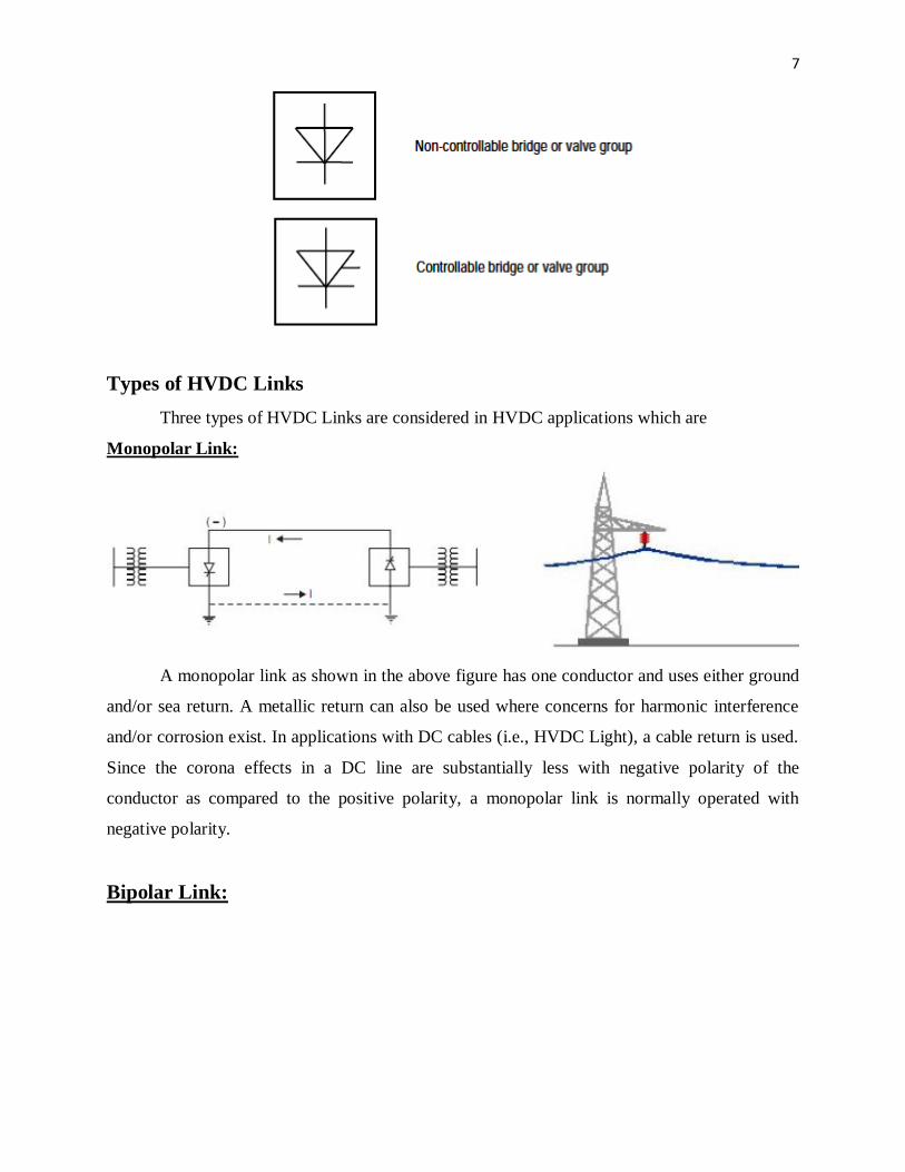
Monopolar Link:
A monopolar link as shown in the above figure has one conductor and uses either ground
and/or sea return. A metallic return can also be used where concerns for harmonic interference
and/or corrosion exist. In applications with DC cables (i.e., HVDC Light), a cable return is used.
Since the corona effects in a DC line are substantially less with negative polarity of the
conductor as compared to the positive polarity, a monopolar link is normally operated with
negative polarity.
Bipolar Link:

8
A bipolar link as shown in the above figure has two conductors, one positive and the
other negative. Each terminal has two sets of converters of equal rating, in series on the DC side.
The junction between the two sets of converters is grounded at one or both ends by the use of a
short electrode line. Since both poles operate with equal currents under normal operation, there is
zero ground current flowing under these conditions. Monopolar operation can also be used in the
first stages of the development of a bipolar link. Alternatively, under faulty converter conditions,
one DC line may be temporarily used as a metallic return with the use of suitable switching.
Homopolar Link:
In this type of link as shown in the above figure two conductors having the same polarity
(usually negative) can be operated with ground or metallic return.
Due to the undesirability of operating a DC link with ground return, bipolar links are
mostly used. A homopolar link has the advantage of reduced insulation costs, but the
disadvantages of earth return outweigh the advantages.
HVDC Converter Station

9
The major components of a HVDC transmission system are converter stations where
conversions from AC to DC (Rectifier station) and from DC to AC (Inverter station) are
performed. A point to point transmission requires two converter stations. The role of rectifier and
inverter stations can be reversed (resulting in power reversals) by suitable converter control.
A typical converter station with two 12 pulse converter units per pole is shown in figure
below. The block diagram of converter station is given above.
Converter Unit:

10
This usually consists of two three phase converter bridges connected in series to form a
12 pulse converter unit as shown in above figure. The total number of valves in such a unit is
twelve. The valves can be packaged as single valve, double valve or quadrivalve arrangements.
Each valve is used to switch in segment of an AC voltage waveform. The converter is fed by
converter transformers connected in star/star and star/delta arrangements.
The valves are cooled by air, oil, water of freon. Liquid cooling using deionized water is
more efficient and results in the reduction of station losses. The design of valves is based on the
modular concept where each module contains a limited number of series connected thyristor
levels.
Valve firing signals are generated in the converter control at ground potential and are
transmitted to each thyristor in the valve through a fiber optic light guide system.
The valves are protected using snubber circuits, protective firing and gapless surge
arrestors.
Converter Transformer:
The converter transformer has three different configurations-
(i) three phase, two winding,
(ii) single phase, three winding and
(iii)single phase, two winding
The valve side windings are connected in parallel with neutral grounded. The leakage
reactance of the transformer is chosen to limit the short circuit currents through any valves.

11
The converter transformers are designed to withstand DC voltage stresses and increased
eddy current losses due to harmonic currents. One problem that can arise is due to the DC
magnetization of the core due to unsymmetrical firing of valves.
Filters:
There are three types of filters used which are
1. AC Filters:
These are passive circuits used to provide how impedance, shunt paths for AC
harmonic currents. Both tuned and damped filter arrangements are used.
2. DC Filters:
These are similar to AC filters and are used for the filtering of DC harmonics.
3. High Frequency (RF/PLC) Filters:
These are connected between the converter transformer and the station AC bus to
suppress any high frequency currents. Sometimes such filters are provided on high-voltage DC
bus connected between the DC filter and DC line and also on the neutral side.
Reactive power source:
Converter stations require reactive power supply that is dependent on the active power
loading. But part of the reactive power requirement is provided by AC filters. In addition, shunt
capacitors, synchronous condensors and static VAR systems are used depending on the speed of
control desired.
Smoothing Reactor:
A sufficiently large series reactor is used on DC side to smooth DC current and also for
protection. The reactor is designed as a linear reactor and is connected on the line side, neutral
side or at intermediate location.
DC Switchgear:
It is modified AC equipment used to interrupt small DC currents. DC breakers or
Metallic Return Transfer Breakers (MRTB) are used, if required for interruption of rated load
currents.
In addition to the DC switchgear, AC switchgear and associated equipment for protection
and measurement are also part of the converter station.
Modern Trends in DC Transmission
To overcome the losses and faults in AC transmission, HVDC transmission is preferred.

12
The trends which are being introduced are for the effective development to reduce the
cost of the converters and to improve the performance of the transmission system.
Power semiconductors and valves:
The IGBTs or GTOs employed required huge amount of current to turn it ON which was
a big problem. GTOs are available at 2500V and 2100A. As the disadvantage of GTOs is the
large gate current needed to turn them OFF, so MCT which can be switched OFF by a small
current is preferred as valves.
The power rating of thyristors is also increased by better cooling methods. Deionized
water cooling has now become a standard and results in reduced losses in cooling.
Converter Control:
The development of micro-computer based converter control equipment has made
possible to design systems with completely redundant converter control with automatic transfer
between systems in the case of a problem.
The micro-computer based control also has the flexibility to implement adaptive control
algorithms or even the use of expert systems for fault diagnosis and protection.
DC Breakers:
Parallel rather than series operation of converters is likely as it allows certain flexibility
in the planned growth of a system. The DC breaker ratings are not likely to exceed the full load
ratings as the control intervention is expected to limit the fault current.
Conversion of existing AC lines:
There are some operational problems due to electromagnetic induction from AC circuits
where an experimental project of converting a single circuit of a double circuit is under process.
Operation with weak AC systems:
The strength of AC systems connected to the terminals of a DC link is measured in terms
of Short Circuit Ratio (SCR) which is defined as
SCR = Short circuit level at the converter bus
Rated DC Power
If SCR is less than 3, the AC system is said to be weak. The conventional constant
extinction angle control may not be suitable for weak AC systems.

13
Constant reactive current control or AC voltage control may overcome some of the
problems of weak AC systems.
The power modulation techniques used to improve dynamic stability of power systems
will have to be modified in the presence of weak AC systems.
Six Pulse Converters
The conversion from AC to DC and vice-versa is done in HVDC converter stations by
using three phase bridge converters. The configuration of the bridge (also called Graetz circuit)
is a six pulse converter and the 12 pulse converter is composed of two bridges in series supplied
from two different (three-phase) transformers with voltages differing in phase by 30o .
Pulse Number
The pulse number of a converter is defined as the number of pulsations (cycles of ripple)
of direct voltage per cycle of alternating voltage.
The conversion from AC to DC involves switching sequentially different sinusoidal
voltages onto the DC circuit.

14
A valve can be treated as a controllable switch which can be turned ON at any instant,
provided the voltage across it is positive.
The output voltage Vd of the converter consists of a DC component and a ripple whose
frequency is determined by the pulse number
Choice of Converter Configuration
The configuration for a given pulse number is so chosen in such a way that the valve and
transformer are used to the maximum.
A converter configuration can be defined by the basic commutation group and the
number of such groups connected in series and parallel.
If there are ‘q’ valves in a basic commutation group and r of those are connected in
parallel and s of them in series then,
p = q r s
Note:

15
A commutation group is defined as the group of valves in which only one (neglecting
overlap) conducts at a time.
Valve Rating:
The valve rating is specified in terms of Peak Inverse Voltage (PIV). The ratio of PIV to
average DC voltage is an index of valve utilization.
So, average maximum DC voltage across the converter is given by,
q
q
mdo ttdEq
sV
)(cos2
qE
sq
qqE
sqtE
qs mm
q
qm
sin2.
2sinsin
2)(sin
2
/
/
qE
sqV mdo
sin ----- (1)
If ‘q’ is even, then maximum inverse voltage occurs when the valve with a phase
displacement of 180o is conducting and is given by,
PIV = 2Em
If ‘q’ is odd, then maximum inverse voltage occurs when the valve with a phase shift of
π±(π/q) is conducting and is given by,
PIV = 2Em cos(π/2q)
The valve utilization factor is given by
For q even,
qqs
qE
sq
E
V
PIV
m
m
do
sin..
2
sin
2
For q odd,
qqsq
q
qsq
q
qE
sq
qE
V
PIV
m
m
do
2sin
2cos2.
2cos.2
sin.
2cos.2
sin
2cos2
(Since sin2θ=2sinθcosθ andqqqq
sin
2
2sin
2sin
2cos2 )

16
qsq
V
PIV
do
2sin.
(For q odd)
Transformer Rating:
The current rating of a valve is given by,
qr
II d
v ------ (2)
where, Id is the DC current which is assumed to be constant.
The transformer rating on the valve side (in VA) is given by,
v
m
tv IE
pS2

17
From equations (1), (2) & p=qrs, we have
qr
I
qsq
VpS ddo
tv .
sin..2
.
IVS ddo
tv
sin.
.2
Transformer utilization factor
ddo
tv
IV
S is a function of q.
As AC supply is three phase so, commutation group of three valves can be easily
arranged. So, for q = 3,
3sin)32(
XIV
S
ddo
tv
oddo
tv
IV
S
60sin6
48.1ddo
tv
IV
S
Transformer utilization can be improved if two valve groups can share single transformer
winding. In this case, the current rating of the winding can be increased by a factor of √2 while
decreasing the number of windings by a factor of 2.

18
It is a 6-pulse converter consisting of two winding transformer where the transformer
utilization factor is increased when compared to three winding transformer.
The series conduction of converter groups has been preferred because of controlling and
protection as well as the requirements for high voltage ratings. So, a 12 pulse converter is
obtained by series connection of two bridges.
The 30o phase displacement between two sets of source voltages is achieved by
transformer connections Y-Y for one bridge and Y-∆ for the other bridge.
The use of a 12 pulse converter is preferable over the 6 pulse converter because of the
reduced filtering requirements.
Analysis of Graetz Circuit without overlap:
At any instant, two valves are conducting in the bridge, one from the upper commutation
group and the second from the lower commutation group. The firing of the next valve in a
particular group results in the turning OFF of the valve that is already conducting. The valves are
numbered in the sequence in which they are fired. Each valve conducts for 120o and the interval
between consecutive firing pulse is 60o in steady state.
The following assumptions are made to simplify the analysis
a. The DC current is constant.
b. The valves are modeled as ideal switches with zero impedance when ON and with
infinite impedance when OFF.
c. The AC voltages at the converter bus are sinusoidal and remain constant.
One period of the AC supply voltage can be divided into 6 intervals – each corresponding
to the conduction of a pair of valves. The DC voltage waveform repeats for each interval.
Assuming the firing of valve 3 is delayed by an angle α , the instantaneous DC voltage
Vd during the interval is given by
Vd = eb – ec = ebc for α ≤ ωt ≤ α+60o
Let tEe LLba sin2
then )60sin(2 o
LLbc tEe
Average DC Voltage =
o
tdtEV o
LLd
60
)60sin(23
)]120cos(60[cos(23 oo
LLE
19
cos35.1cos23
LLLLd EEV
cosdod VV ------- (1)
The above equation indicates that for different values of α , Vd is variable.
The range of α is 180o and correspondingly Vd can vary from Vdo to –Vdo . Thus, the
same converter can act as a rectifier or inverter depending upon whether the DC voltage is
positive or negative.
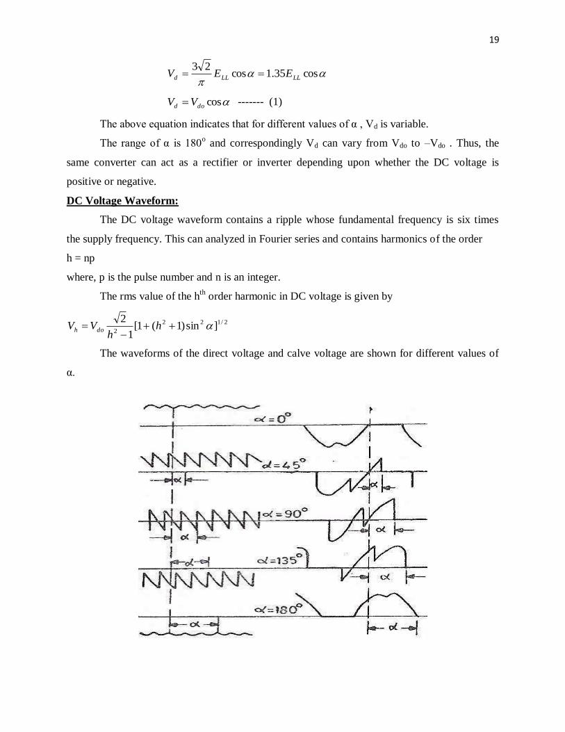
DC Voltage Waveform:
The DC voltage waveform contains a ripple whose fundamental frequency is six times
the supply frequency. This can analyzed in Fourier series and contains harmonics of the order
h = np
where, p is the pulse number and n is an integer.
The rms value of the hth
order harmonic in DC voltage is given by
2/122
2]sin)1(1[
1
2
h
hVV doh
The waveforms of the direct voltage and calve voltage are shown for different values of
α.

20
AC Current Waveform:
It is assumed that direct current has no ripple (or harmonics). The AC currents flowing
through the valve (secondary) and primary windings of the converter transformer contain
harmonics.
The waveform of the current in a valve winding is shown. The rms value of the
fundamental component of current is given by
dd IdII
6.cos
2
2
13/
3/
1
---- (2)
where as the rms value of the current is
dII .3
2
The harmonics contained in the current waveform are of the order given by
1 nph
Where n is an integer, p is the pulse number. For a six pulse converter, the order of AC
harmonics is 5, 7, 11, 13 and higher order. These are filtered out by using tuned filters for each
one of the first four harmonics and a high pass filter for the remaining.
The rms value of hth
harmonic is given by h
II h
1
Power Factor:
The AC power supplied to the converter is given by
cos3 1IEP LLAC
Where cos is the power factor.
The DC power must match the AC power ignoring the losses in the converter. Thus,
cos3 1IEIVPP LLddoDCAC
Substituting for Vdo and I1 from equations (1) and (2) in the above equation, we get
coscos

21
The reactive power requirements are increased as α is increased from zero (or reduced
from 180o ).
Analysis of Graetz Circuit with overlap
Due to the leakage inductance of the converter transformers and the impedance in the
supply network, the current in a valve cannot change suddenly and this commutation from one
valve to the next cannot be instantaneous. This is called overlap and its duration is measured by
the overlap (commutation) angle ‘μ’.
Each interval of the period of supply can be divided into two subintervals as shown in the
below timing diagram. In the first subinterval, three valves are conducting and in the second
subinterval, two valves are conducting which is based on the assumption that the overlap angle is
less than 60o .
There are three modes of the converter which are
i) Mode 1 – Two and three valve conduction (μ<60o )
ii) Mode 2 – Three valve conduction (μ=60o )
iii) Mode 3 – Three and four valve conduction (μ>60o )
i)Analysis of Two and Three Valve Conduction Mode:
The equivalent circuit for three valve conduction is shown below.
For this circuit,
dt
di
dt
diLee cab
13
The LHS in the above equation is called the commutating emf whose value is given by
tEee LLab sin2
Which is the voltage across valve 3 just before it starts conducting.

22
Since, 31 iIi d
We get,
dt
diLtE cLL
32sin2
Solving the above equation, we get
ttIti s ),cos(cos)(3
Where,
c
LLs
L
EI
2
2
At ωt=α+μ , is = Id . This gives )]cos([cos sd II
The average direct voltage can be obtained as
60
)()()(2
33
tdeetdeV cbcd
)]cos([cos22
3cos
LLdo EV
Since, doLL VE
23 , we get
)]cos([cos2
do
d
VV
The value of )]cos([cos can be substituted to get,
dcdo
s
d
dod IRVI
IVV
cos
2cos
Where,
ccc XLR
33
Rc is called equivalent commutation resistance and the equivalent circuit for a bridge
converter is shown below.

23
Inverter Equations:
For an inverter, advance angle β is given by
β=π-α
and use opposite polarity for the DC voltage with voltage rise opposite to the direction of
current. Thus,
)]cos([cos2
doi
di
VV
)]cos()[cos(2
doiV
]cos[cos2
doi
di
VV
Where, the extinction angle γ is defined as
γ = β-μ = π-α-μ
Similarly, it can be shown that
dcidoidi IRVV cos
dcidoi IRV cos
The subscript “i” refers to the inverter.
ii) Analysis of Three and Four Valve Conduction Mode:
The equivalent circuit for three and four valve conduction is shown below.
For, α ≤ ωt ≤ α+μ-60o
i1 = Is sin(ωt+60o ) + A
i6 = Id – i2 = Id – Is sinωt + C
Where, s
c
m
s IL
EI
3
2
The constant A can be determined from the initial condition
i1 (ωt=α) = Id = Is sin(α+60o ) + A
The constant C can be determined from the final condition
i6 (ωt=α+μ-60o ) = 0 = Id – Is sin(α+μ-60
o ) + C = 0

24
For, α+μ-60o ≤ ωt ≤ α+60
0
i1 = Is cosωt + B
The constant B can be determined from the continuity equation
i1 (ωt=α+μ=60o ) = Is sin(α+μ) + A = Is cos(α+μ-60
o ) + B
Finally,
)]30cos()30[cos(2
oos
d
II
The expression for average direct voltage is given by
)(2
3360
60
tdeV
o
o
cd
Since ec = Em cosωt
)]60sin()60[sin(2
33 oo
md EV
)]30cos()30[cos(2
3 oo
dod VV
Finally
dc
o
do
s
do
dod IRVI
IVV 3)30cos(.3]
2
3)30cos(3[
Converter Bridge Characteristics
A) Rectifier: The rectifier has three modes of operation.
1) First mode: Two and three valve conduction mode ( μ < 60o )
2) Second mode: Three valve conduction mode only for α < 30o ( μ = 60
o )
3) Third mode: Three and four valve conduction mode α ≥ 30o ( 60
o ≤ μ ≤ 120
o )
As the DC current continues to increase, the converter operation changes over from
mode 1 to 2 and finally to mode 3.
The DC voltage continues to decrease until it reaches zero.

25
For α ≥ 30o , mode 2 is bypassed.
For Modes 1 and 3, we have
s
d
do
d
I
I
V
V
2cos
s
do
do
d
I
I
V
V
2
3)30cos(3
The voltage and current characteristics are linear with different slopes in these cases.
For mode 2, μ = 60o , μ is constant, so the characteristics are elliptical and is given by
1
2sin
2cos
2
|
2
|
dd IV
where, do
d
dV
VV | and
s
d
dI
II
2
|
B) Inverter:
The inverter characteristics are similar to the rectifier characteristics. However, the
operation as an inverter requires a minimum commutation margin angle during which the voltage
across the valve is negative. Hence the operating region of an inverter is different from that for a
rectifier.
So, the margin angle (ξ) has different relationship to γ depending on the range of
operation which are
First Range: β < 60o and ξ = γ
Second Range: 60o < β < 90
o and ξ =60
o – μ = γ-(β-60
o )
Third Range: β > 90o and ξ = γ – 30
o
In the inverter operation, it is necessary to maintain a certain minimum margin angle ξo
which results in 3 sub-modes of the 1st mode which are
Mode 1
1(a) β < 60o for values of μ < (60
o - ξo )
The characteristics are linear defined by
Vd| = cosγo – Id
|
1(b) 60o < β < 90
o for
μ = 60o – ξo = 60
o – γo = constant

26
The characteristics are elliptical.
1(c) 90o < β < 90
o + ξo for values of μ in the range
60o – ξo ≤ μ ≤ 60
o
The characteristics in this case are line and defined by
Vd| = cos( γo + 30
o ) - Id
|
Mode 2
For μ > 60o corresponding to β > 90
o + γo
The characteristics again are linear but with a different slope and is defined by
Vd| = √3 cosγo - 3Id
|
In the normal operation of the converter Id| is in the range of 0.08 to 0.1 .
Characteristics of a twelve pulse converter
As long as the AC voltages at the converter bus remain sinusoidal (with effective
filtering), the operation of one bridge is unaffected by the operation of the other bridge connected
in series. The region of rectifier operation can be divided into five modes as
Mode 1: 4 and 5 valve conduction
0 < μ < 30o
Mode 2: 5 and 6 valve conduction
30o < μ < 60
o
Mode 3: 6 valve conduction
0 < α < 30o , μ = 60
o
Mode 4: 6 and 7 valve conduction
60o < μ < 90
o

27
Mode 5: 7 and 8 valve conduction
90o < μ < 120
o
The second mode is a continuation of the first and similarly fifth is a continuation of the
fourth.
The equivalent circuit of the twelve pulse converter is the series combination of the
equivalent circuits for the two bridges. This is because the two bridges are connected in series on
the DC side and in parallel on the AC side. The current waveforms in the primary winding of the
star/star and star/delta connected transformers and the line current injected into the converter bus
are shown.
Questions
1) What is the need for interconnection of systems? Explain the merits of connecting HVAC
systems by HVDC tie-lines?
2) (a) Discuss the different factors that favor HVDC transmission systems over EHVAC
transmission over long distances.
(b) What are the different HVDC links normally adopted?
3) (a) With the help of a neat schematic diagram of a typical HVDC converter station explain the
functions of various components available.
(b) What are the applications and merits of HVDC transmission system?
4) (a) Explain for what reasons as a system planner, you consider the applications of HVDC in
India?

28
(b) Compare HVDC transmission system with AC system in all aspects.
5) For a 3-Φ, 6 pulse Graetz’s circuit, draw the timing diagram considering overlap angle is less
than 60o and without overlap for the following:
(a) Voltage across load
(b) Voltage across any two pair of conduction values
6) Explain the operation of a 12 pulse bridge rectifier with the help of circuit diagram, voltage &
current waveforms.
7) (a) Clearly explain how harmonics are produced and obtain the expression for rms value of the
fundamental component of the current.
(b) Obtain a relation between firing angle and power factor angle in a 3-Φ bridge rectifier.
8) Derive the expression for average DC voltages of a six pulse bridge converter, considering
gate control and source reactance.
9) What is the reason for using star-star and star-delta transformer configurations for 12 pulse
converter? Derive an equation for primary current using fourier analysis.

29
UNIT-III: CONTROL OF HVDC CONVERTER SYSTEMS
The major advantage of a HVDC link is rapid controllability of transmitted power
through the control of firing angles of the converters. Modern converter controls are not only
fast, but also very reliable and they are used for protection against line and converter faults.
Principles of DC Link Control
The control of power in a DC link can be achieved through the control of current or
voltage. From minimization of loss considerations, we need to maintain constant voltage in the
link and adjust the current to meet the required power.
Consider the steady state equivalent circuit of a two terminal DC link. This is based on
the assumption that all the series connected bridges in both poles of a converter station are
identical and have the same delay angles. Also the number of series connected bridges (nb ) in
both stations (rectifier and inverter) are the same.
The voltage sources Edr and Edi are defined by
Edr = (3√2/π) nb Evr cosαr ---- (1)
Edi = (3√2/π) nb Evi cosγi ---- (2)

30
where Evr and Evi are the line to line voltages in the valve side windings of the rectifier
and inverter transformer respectively. From the above figure these voltages can be obtained by
rpr
rsr
vrTN
ENE ,
ipi
isi
viTN
ENE ---- (3)
where Er and Ei are the AC (line to line) voltages of the converter buses on the rectifier
and inverter side. Tr and Ti are the OFF-nominal tap ratios on the rectifier and inverter side.
Combining equations (1), (2) and (3),
Edr = (Ar Er /Tr) cosαr ---- (4)
Edi = (Ai Ei /Ti) cosγi ---- (5)
where Ar and Ai are constants.
The steady-state current Id in the DC link is obtained as
cidcr
didr
dRRR
EEI
)(
Substituting equations (4) and (5) in the above equation, we get
cidcr
iiiirrrr
dRRR
TEATEAI
cos)/(cos)/(
The control variables in the above equation are Tr , Ti and αr , βi . However, for
maintaining safe commutation margin, it is convenient to consider γi as control variable instead
of βi .
As the denominator in the final equation is small, even small changes in the voltage
magnitude Er or Ei can result in large changes in the DC current, the control variables are held
constant. As the voltage changes can be sudden, it is obvious that manual control of converter
angles is not feasible. Hence, direct and fast control of current by varying αr or γr in response to a
feedback signal is essential.
While there is a need to maintain a minimum extinction angle of the inverter to avoid
commutation failure, it is economical to operate the inverter at Constant Extinction Angle (CEA)
which is slightly above the absolute minimum required for the commutation margin. This results
in reduced costs of the inverter stations, reduced converter losses and reactive power
consumption. However, the main drawback of CEA control is the negative resistance
characteristics of the converter which makes it difficult to operate stably when the AC system is
weak (low short-circuit ratios). Constant DC Voltage (CDCV) control or Constant AC Voltage
(CACV) control are the alternatives that could be used at the inverter.

31
Under normal conditions, the rectifier operates at Constant Current (CC) control and the
inverter at the CEA control.
The power reversal in the link can take place by the reversal of the DC voltage. This is
done by increasing the delay angle at the station initially operating as a rectifier, while reducing
the delay angle at the station initially operating as the inverter. Thus, it is necessary to provide
both CEA and CC controllers at both terminals.
The feedback control of power in a DC link is not desirable because
1) At low DC voltages, the current required is excessive to maintain the required level of
power. This can be counterproductive because of the excessive requirements of the
reactive power, which depresses voltage further.
2) The constant power characteristic contributes to negative damping and degrades dynamic
stability.
Converter Control Characteristics
Basic Characteristics:
The intersection of the two characteristics (point A) determines the mode of operation-
Station I operating as rectifier with constant current control and station II operating at constant
(minimum) extinction angle.
There can be three modes of operation of the link (for the same direction of power flow)
depending on the ceiling voltage of the rectifier which determines the point of intersection of the
two characteristics which are defined below
1) CC at rectifier and CEA at inverter (operating point A) which is the normal mode of
operation.
2) With slight dip in the AC voltage, the point of intersection drifts to C which implies
minimum α at rectifier and minimum γ at the inverter.
3) With lower AC voltage at the rectifier, the mode of operation shifts to point B which
implies CC at the inverter with minimum α at the rectifier.

32
The characteristic AB has generally more negative slope than characteristic FE because
the slope of AB is due to the combined resistance of (Rd + Rcr ) while is the slope of FE is due to
Rci .
The above figure shows the control characteristics for negative current margin Im (or
where the current reference of station II is larger than that of station I). The operating point shifts
now to D which implies power reversal with station I (now acting as inverter) operating with
minimum CEA control while station II operating with CC control.
This shows the importance of maintaining the correct sign of the current margin to avoid
inadvertent power reversal. The maintenance of proper current margin requires adequate
telecommunication channel for rapid transmission of the current or power order.
Voltage Dependent Current Limit:
The low voltage in the DC link is mainly due to the faults in the AC system on the
rectifier or inverter side. The low AC voltage due to faults on the inverter side can result in

33
persistent commutation failure because of the increase of the overlap angle. In such cases, it is
necessary to reduce the DC current in the link until the conditions that led to the reduced DC
voltage are relieved. Also the reduction of current relieves those valves in the inverter which are
overstressed due to continuous current flow in them.
If the low voltage is due to faults on the rectifier side AC system, the inverter has to
operate at very low power factor causing excessive consumption of reactive power which is also
undesirable. Thus, it becomes useful to modify the control characteristics to include voltage
dependent current limits. The figure above shown shows current error characteristics to stabilize
the mode when operating with DC current between Id1 and Id2 . The characteristic cc| and c
|c
||
show the limitation of current due to the reduction in voltage.
System Control Hierarchy
The control function required for the HVDC link is performed using the hierarchical
control structure.

34
The master controller for a bipole is located at one of the terminals and is provided with
the power order (Pref ) from the system controller (from energy control centre). It also has other
information such as AC voltage at the converter bus, DC voltage etc. The master controller
transmits the current order (Iref ) to the pole control units which in turn provide a firing angle
order to the individual valve groups (converters). The valve group or converter control also
oversees valve monitoring and firing logic through the optical interface. It also includes bypass
pair selection logic, commutation failure protection, tap changer control, converter start/stop
sequences, margin switching and valve protection circuits.
The pole control incorporated pole protection, DC line protection and optional converter
paralleling and deparalleling sequences. The master controller which oversees the complete
bipole includes the functions of frequency control, power modulation, AC voltage and reactive
power control and torsional frequency damping control.
The current or extinction angle controller generates a control signal Vc which is related to
the firing angle required. The firing angle controller generates gate pulses in response to the
control signal Vc . The selector picks the smaller of the α determined by the current and CEA
controllers.
Firing Angle Control
The operation of CC and CEA controllers is closely linked with the method of generation
of gate pulses for the valves in a converter. The requirements for the firing pulse generation of
HVDC valves are

35
1. The firing instant for all the valves are determined at ground potential and the firing
signals sent to individual thyristors by light signals through fibre-optic cables. The
required gate power is made available at the potential of individual thyristor.
2. While a single pulse is adequate to turn-on a thyristor, the gate pulse generated must send
a pulse whenever required, if the particular valve is to be kept in a conducting state.
The two basic firing schemes are
1. Individual Phase Control (IPC)
2. Equidistant Pulse Control (EPC)
Individual Phase Control (IPC)
This was used in the early HVDC projects. The main feature of this scheme is that the
firing pulse generation for each phase (or valve) is independent of each other and the firing
pulses are rigidly synchronized with commutation voltages.
There are two ways in which this can be achieved
1. Constant α Control
2. Inverse Cosine Control
Constant α Control
Six timing (commutation) voltages are derived from the converter AC bus via voltage
transformers and the six gate pulses are generated at nominally identical delay times subsequent
to the respective voltage zero crossings. The instant of zero crossing of a particular commutation
voltage corresponds to α = 0o for that valve.
The delays are produced by independent delay circuits and controlled by a common
control voltage V derived from the current controllers.
Inverse Cosine Control
The six timing voltages (obtained as in constant α control) are each phase shifted by 90o
and added separately to a common control voltage V.

36
The zero crossing of the sum of the two voltages initiates the firing pulse for the
particular valve is considered. The delay angle α is nominally proportional to the inverse cosine
of the control voltage. It also depends on the AC system voltage amplitude and shape.
The main advantage of this scheme is that the average DC voltage across the bridge
varies linearly with the control voltage Vc .
Drawbacks of IPC Scheme
The major drawback of IPC scheme is the aggravation of the harmonic stability problem
that was encountered particularly in systems with low short circuit ratios (less than 4). The
harmonic instability, unlike instability in control systems, is a problem that is characterized by
magnification of noncharacteristic harmonics in steady-state.
This is mainly due to the fact that any distortion in the system voltage leads to
perturbations in the zero crossings which affect the instants of firing pulses in IPC scheme. This
implies that even when the fundamental frequency voltage components are balanced, the firing

37
pulses are not equidistant in steady-state. This in turn leads to the generation of noncharacteristic
harmonics (harmonics of order h ≠ np ± 1) in the AC current which can amplify the harmonic
content of the AC voltage at the converter bus. The problem of harmonic instability can be
overcome by the following measures
1. Through the provision of synchronous condensers or additional filters for filtering out
noncharacteristic harmonics.
2. Use of filters in control circuit to filter out noncharacteristic harmonics in the
commutation voltages.
3. The use of firing angle control independent of the zero crossings of the AC voltages. This
is the most attractive solution and leads to the Equidistant Pulse Firing scheme.
Equidistant Pulse Control (EPC)
The firing pulses are generated in steady-state at equal intervals of 1/pf , through a ring
counter. This control scheme uses a phase locked oscillator to generate the firing pulses. Thre are
three variations of the EPC scheme
1. Pulse Frequency Control (PFC)
2. Pulse Period Control
3. Pulse Phase Control (PPC)
Pulse Frequency Control (PFC)
A Voltage Controlled Oscillator (VCO) is used, the frequency of which is determined by
the control voltage Vc which is related to the error in the quantity (current, extinction angle or
DC voltage) being regulated. The frequency in steady-state operation is equal to pfo where fo is
the nominal frequency of the AC system. PFC system has an integral characteristic and has to be
used along with a feedback control system for stabilization.
The Voltage Controlled Oscillator (VCO) consists of an integrator, comparator and a
pulse generator.

38
The output pulses of the generator drive the ring counter and also reset the integrator. The
instant (tn ) of the firing pulse is determined by
n
n
t
t
c VdtVVK
1
311 )(
where V1 is a bias (constant) voltage and V3 is proportional to the system period.
In steady-state, Vc = 0, and from the above equation, we get
K1 V1 (tn – tn-1 ) = V3
Since, tn – tn-1 = 1/pfo
in steady-state, the gain K1 of the integrator is chosen as
K1 = pfo V3 / V1
The circuit does not incorporate frequency correction (when the system frequency
deviates from fo ). The frequency correction is obtained by deriving V3 as
V3 = V2 / (1+ST1 ) , V2 = K1 V1 (tn-1 – tn-2 )
Pulse Period Control
It is similar to PFC except for the way in which the control voltage Vc is handled. The
structure of the controller is the same, however, Vc is now summed with V3 instead of V1 . Thus,
the instant tn of the pulse generation is

39
n
n
t
t
cVVdtVK
1
311
K1 V1 (tn – tn-1 ) = V3 + Vc
With Vc = 0, the interval between consecutive pulses, in steady-state, is exactly equal to
1/pfo .
The frequency correction in this scheme is obtained by either updating V1 in response to
the system frequency variation or including another integrator in the CC or CEA controller.
Pulse Phase Control (PPC)
An analog circuit is configured to generate firing pulses according to the following equation
3)1(11
1
VVVdtVKn
n
t
t
nccn
where Vcn and Vc(n-1) are the control voltages at the instants tn and tn-1 respectively.
For proportional current control, the steady-state can be reached when the error of Vc is
constant.
The major advantages claimed for PPC over PFC are (i) easy inclusion of α limits by
limiting Vc as in IPC and (ii) linearization of control characteristic by including an inverse cosine
function block after the current controller. Limits can also be incorporated into PFC or pulse
period control system.
Drawbacks of EPC Scheme
EPC Scheme has replaced IPC Scheme in modern HVDC projects; it has certain
limitations which are
1. Under balanced voltage conditions, EPC results in less DC voltage compared to IPC.
Unbalance in the voltage results from single phase to ground fault in the AC system

40
which may persist for over 10 cycles due to stuck breakers. Under such conditions, it is
desirable to maximize DC power transfer in the link which calls for IPC.
2. EPC Scheme also results in higher negative damping contribution to torsional oscillat ions
when HVDC is the major transmission link from a thermal station.
Current and Extinction Angle Control
The current controller is invariably of feedback type which is of PI type.
The extinction angle controller can be of predictive type or feedback type with IPC
control. The predictive controller is considered to be less prone to commutation failure and was
used in early schemes. The feedback control with PFC type of Equidistant Pulse Control
overcomes the problems associated with IPC.
The extinction angle, as opposed to current, is a discrete variable and it was felt the
feedback control of gamma is slower than the predictive type. The firing pulse generation is
based on the following equation
0 = dc
t
cj IXtden
n
2)(
1
where ecj is the commutation voltage across valve j and tn is the instant of its firing.
In general, the prediction of firing angle is based on the equation
Βj = γref + µj
where µj is the overlap angle of valve j, which is to be predicted based on the current knowledge
of the commutation voltage and DC current.
Under large disturbances such as a sudden dip in the AC voltage, signals derived from the
derivative of voltage or DC current aid the advancing of delay angle for fast recovery from
commutation failures.

41
Starting and Stopping of DC Link
Energization and Deenergization of a Bridge:
Consider N series connected bridges at a converter station. If one of the bridges is to be
taken out of service, there is need to not only block, but bypass the bridge. This is because of the
fact that just blocking the pulses does not extinguish the current in the pair of valves that are left
conducting at the time of blocking. The continued conduction of this pair injects AC voltage into
the link which can give rise to current and voltage oscillations due to lightly damped oscillatory
circuit in the link formed by smoothing reactor and the line capacitance. The transformer feeding
the bridge is also subjected to DC magnetization when DC current continues to flow through the
secondary windings.
The bypassing of the bridge can be done with the help of a separate bypass valve or by
activating a bypass pair in the bridge (two valves in the same arm of the bridge). The bypass
valve was used with mercury arc valves where the possibility of arc backs makes it impractical to
use bypass pairs. With thyristor valves, the use of bypass pair is the practice as it saves the cost
of an extra valve.
With the selection of bypass pair 1 and 4, the commutation from valve 2 to4 is there, but
the commutation from valve 3 to valve 5 is prevented. In the case of a predetermined choice of
the bypass path, the time lapse between the blocking command and the current transfer to bypass
path can vary from 600 and 180
0 for a rectifier bridge. In the inverter, there is no time lag
involved in the activation of the bypass pair. The voltage waveforms for the rectifier and inverter
during de-energisation are shown below where the overlap is neglected.

42
The current from bypass pair is shunted to a mechanical switch S1 . With the aid of the
isolators S, the bridge can be isolated. The isolator pair S and switch S1 are interlocked such that
one or both are always closed.
The energisation of a blocked bridge is done in two stages. The current is first diverted
from S1 to the bypass pair. For this to happen S1 must generate the required arc voltage and to
minimize this voltage, the circuit inductance must be small. In case the bypass pair fails to take
over the current, S1 must close automatically if the current in that does not become zero after a
predetermined time interval. AC breakers with sufficient arc voltage, but with reduced breaking
capacity are used as switch S1 .
In the second stage of energisation, the current is diverted from the bypass pair. For the
rectifier, this can take place instantaneously neglecting overlap. The voltage waveforms for this
case are shown below.
Start-Up of DC Link:
There are two different start-up procedures depending upon whether the converter firing
controller provides a short gate pulse or long gate pulse. The long gate pulse lasts nearly 1200 ,
the average conduction period of a valve.
Start-up with long pulse firing:
1. Deblock inverter at about γ = 900
2. Deblock rectifier at α = 850 to establish low direct current
3. Ramp up voltage by inverter control and the current by rectifier control.
43
Start-up with short pulse firing:
1. Open bypass switch at one terminal
2. Deblock that terminal and load to minimum current in the rectifier mode
3. Open bypass switch at the second terminal and commutate current to the bypass pair
4. Start the second terminal also in the rectifier mode
5. The inverter terminal is put into the inversion mode
6. Ramp up voltage and current.
The voltage is raised before raising the current. This permits the insulation of the line to
be checked before raising the power. The ramping of power avoids stresses on the generator
shaft. The switching surges in the line are also reduced.
The required power ramping rate depends on the strength of the AC system. Weaker
systems require fast restoration of DC power for maintaining transient stability.
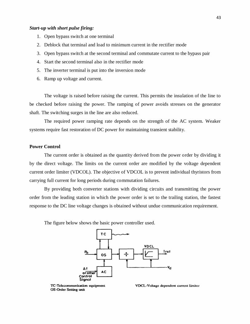
Power Control
The current order is obtained as the quantity derived from the power order by dividing it
by the direct voltage. The limits on the current order are modified by the voltage dependent
current order limiter (VDCOL). The objective of VDCOL is to prevent individual thyristors from
carrying full current for long periods during commutation failures.
By providing both converter stations with dividing circuits and transmitting the power
order from the leading station in which the power order is set to the trailing station, the fastest
response to the DC line voltage changes is obtained without undue communication requirement.
The figure below shows the basic power controller used.

44
When the DC line resistance is large and varies considerably e.g., when
the overhead line is very long and exposed to large temperature variations, the DC line voltage
drop cannot be compensated individually in the two stations. This problem can be solved by
using a current order calculated in one substation only and transmitting its output to the other
substation.
Questions:
1) Write detailed notes on the following
(a) Preductive commutation margin control
(b) Equidistant firing control.
2) (a) Differentiate between the two start-up procedures based upon the pulse.
(b) Describe about starting and stopping of DC link.
3) (a) Explain with neat sketch, constant extinction angle control.
(b) What is meant by current margin between two stations in a HVDC link? Why is the
inverter station, operated as a constant voltage controller under normal conditions?
4) Enumerate the relative merits and demerits of constant current control and constant voltage
control of HVDC link.
5) (a) Explain the necessity of “VDCOL" control in a HVDC link with the help of VI
characteristics..
(b) Explain the procedure of Energization and Deenergization of a converter bridge.
6) (a) Draw the complete converter control characteristics and explain the principle of power
control in a DC link.
(b) Explain Inverse cosine control scheme for firing pulse generations.
7) (a) Explain pulse frequency control scheme for firing pulse generation and discuss its
drawbacks.
(b) Explain clearly the procedure for start up of a DC link.
8) Explain the individual characteristics of a Rectifier and an Inverter with sketches.
9) With block diagram, discuss the principle of operation of a basic power controller.
10) Write short notes on the following:
(a) Constant Alpha control (b) Inverse cosine control.
11) Explain the drawbacks in Individual phase control and equidistant pulse control schemes
used in HVDC projects.

45
Introduction, generation of harmonics, AC & DC Filters, Reactive power
requirements at steady state, sources of reactive power, static VAR systems
Electrical energy transmitted through AC transmission or DC transmission is to be
delivered at the consumer’s terminals at specified voltage level of constant magnitude without
deviation from the ideal waveform.
An HVDC transmission system generates harmonic currents on the AC side and
harmonic voltages on the DC side during operation. The harmonic currents generated at the AC
bus of the converter get transmitted to the AC network and then cause the following adverse
effects.
a) Heating of the equipments connected.
b) Instability of converter control.
c) Generates telephone and radio interference in adjacent communication lines, thereby
inducing harmonic noise.
d) Harmonics can lead to generation of overvoltages due to resonance when filter circuits
are employed.
An HVDC transmission system consists of a rectifier and an inverter whose operation
generates harmonics on AC and DC side of the converter. The three distinct sources of
harmonics in HVDC systems are
1) Transformer.
2) AC Generator.
3) Converter along with its control devices.
Transformer as source of harmonics
Transformers can be considered as source of harmonic voltages, which arise from
magnetic distortion and magnetic saturation due to the presence of a DC component in its
secondary. The magnitude of these harmonics depends upon the operating flux density.
Converter transformers are usually operated at high flux densities than conventional 3-phase
transformers, and therefore the possibility of generation of harmonics is more.
Although the waveform is usually good, an AC generator may be regarded as a source of
balanced harmonics because of non-uniform distribution of flux on the armature windings.

46
The converter which forms the basic unit in HVDC transmission imposes changes of
impedances in the current.
When hysteresis effect is considered, then the non-sinusoidal magnetizing current
waveform is no longer symmetrical which is mainly caused by triple n harmonics and
particularly the third harmonic. Thus, in order to maintain a reasonable sinusoidal voltage
supply, it is necessary to supply a path for triple n harmonics which is achieved by the use of
delta-connected windings.
Harmonics due to Converters
A 12-pulse connection consists of two 6-pulse groups. One group having Y-Y connected
converter transformer with 1:1 turns ratio and the other group having Y-∆ converter transformer
bank with 1:√3 turns ratio.
Generation of Harmonics
The harmonics which are generated are of two types.
(i) Characteristic harmonics.
(ii) Non- characteristic harmonics.
Characteristic Harmonics
The characteristic harmonics are harmonics which are always present even under ideal
operation.

47
In the converter analysis, the DC current is assumed to be constant. But in AC current the
harmonics exist which are of the order of
h = np ± 1
and in DC current it is of the order of
h = np
where n is any integer and p is pulse number.
Neglecting overlap, primary currents of Y-Y and Y-∆ connection of the transformer are
considered taking the origin symmetrical where
i = Id for –π/3≤ ωt≤π/3
= 0 for π/3≤ωt≤2π/3 and for Y-Y connection
-π/3≤ωt≤-2π/3 converter
= - Id for –2π/3≤ ωt≤-π and transformer
2π/3≤ ωt≤π
Figure (a): Phase current on primary side of Y-Y connection converter transformer
Figure (b): Phase current on primary side of Y-∆ connection converter transformer

48
For convenience, the ordinate axis (corresponding to ωt = 0) is chosen such that the
waveform has even symmetry. So, generally, by fourier series
00
0 sincos2
1)(
n
n
n
n tnbtnaatf
As positive and negative half cycle cancel each other, so a0 = 0 and as it is (waveform is)
even symmetry, so bn = 0 due to which f(t) becomes
n
n
n
n tnaortnatf cos)(cos)(0
Therefore, n
nA tnai cos11
where,
nductionPeriodOfCo
n dttfT
a0
)(2
1
Here total time period is T = π and period of conduction is π/3
So,
3/
0
)(cos2
21
ttdnIXa dn
(Here as it is symmetry)
3/
0
3/
0
sin4)(cos
41
n
tnIttdn
Ia dd
n
3sin
41
n
n
Ia d
n
For triplen harmonics, 01na
Questions
1) Derive the relationship between pulse conversion and harmonics generated.
2) What are the various sources of harmonics generation in a HVDC line?
3) (a) Discuss the effect of pulse number and overlap angle on harmonics generated by HVDC
converters.
(b) Using fourier analysis show that the lowest order voltage harmonic present in Graetz
circuit output voltage is six.
4) Analyze the harmonics in the AC current during 6-pulse and 12-pulse operations using fourier
analysis. What orders of harmonics predominate in the current wave?

49
5) (a) Discuss about characteristic and non-characteristic harmonics generated in HVDC
systems.
(b) What are the adverse affects of Harmonics produced by the HVDC converters?
6) It is required to eliminate harmonics of order 10 and below 10 other than fundamental in a 12
pulse converter. Suggest a suitable transformer configuration and derive an equation for primary
current of transformer.
7) Give reasons for selecting star-star and star-delta transformer configuration instead of two
star-star configurations for 12 pulse converter. Derive an equation for primary current.
8) How do you estimate the harmonic order based upon pulse number of HVDC converter
station? Give a detailed harmonic analysis of a 12 pulse converter for characteristic harmonics.
9) What are the different harmonics generated in voltage and current waveform on both AC and
DC side in case of a 6 pulse converter?
10) Discuss the following filters:
(a) Double Tuned Filter (b) High Pass C Type Filter
11) Draw the loci of Network impedance and filter impedance and analyze the impact of network
impendence or admittance on the design of single tuned filter.
12) While listing out the problems associated with the injection of harmonics in a system,
explain what is the major design objective of AC filters? How is their performance measured?
13) What do you understand by term filter? Why is it increasing in a system? Classify filters and
choose the one required for HVDC transmission system.
14) (a) Discuss about various types of AC filters employed in HVDC systems for harmonic
suppression.
(b) Discuss the design aspects of high pass filter.
15) Discuss the design aspects of a single tuned filter and obtain the expression for optimum
value of Q for minimum harmonic voltage.
16) What are the various types of filters that are employed in HVDC converter station?
Discuss them in detail.
17) What are the filter configurations that are employed for HVDC converter station?
Give design aspect of one such filter.
18) Derive an equation for harmonic voltage and current for single tuned filter and discuss the
influence of network admittance on design aspects.
19) Explain in detail, the different configurations of static VAR system.
50
20) (a) Describe the method of compensation of reactive power in HVDC substation.
(b) Draw simple single line schematics for each.
21) What is a Static VAR system? How many types of SVS schemes are present and what are
they?
22) (a) Discuss about alternate converter control strategies for reactive power control.
(b) Discuss how shunt capacitors can be used to meet reactive power requirement of a converter.
23) (a) Why Reactive power control is required for HVDC stations? Discuss about conventional
control strategies for Reactive power control in HVDC link.
(b) Discuss how reactive power requirement is met using synchronous condensers.
25) Write a note on the following sources of reactive power
(a) Synchronous condensers
(b) Static VAR system
Design of AC Filters
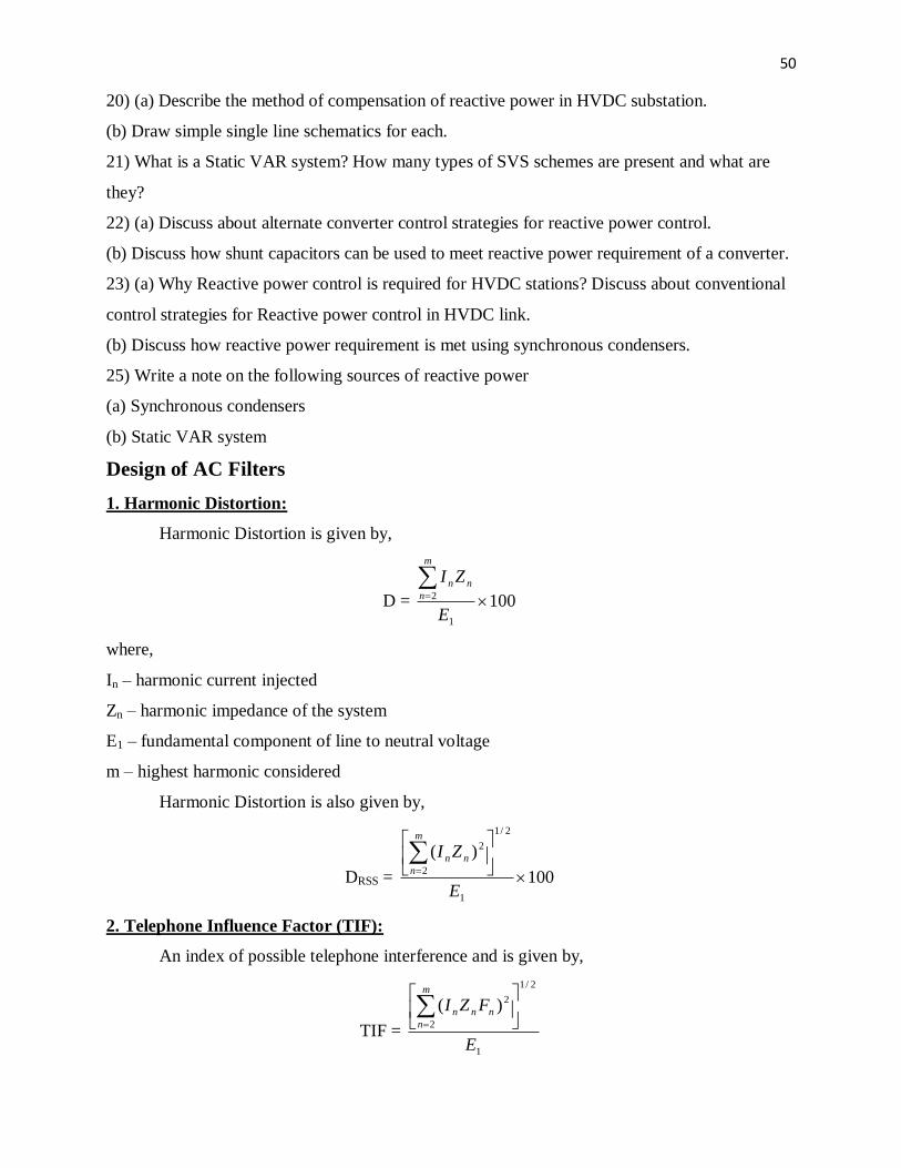
1. Harmonic Distortion:
Harmonic Distortion is given by,
D = 1001
2
E
ZIm
n
nn
where,
In – harmonic current injected
Zn – harmonic impedance of the system
E1 – fundamental component of line to neutral voltage
m – highest harmonic considered
Harmonic Distortion is also given by,
DRSS = 100
)(
1
2/1
2
2
E
ZIm
n
nn
2. Telephone Influence Factor (TIF):
An index of possible telephone interference and is given by,
TIF = 1
2/1
2
2)(
E
FZIm
n
nnn

51
where,
Fn = 5 n f1 pn
Pn is the c message weighting used by Bell Telephone Systems (BTS) and Edison Electric
Institute (EEI) in USA. This weighting reflects the frequency dependent sensitivity of the human
ear and has a maximum value at the frequency of 1000Hz.
3. Telephone Harmonic Form Factor (THFF):
It is similar to TIF and is given by,
Fn = (n f1 / 800) Wn
where,
Wn – weight at the harmonic order n, defined by the Consultative Commission on Telephone and
Telegraph Systems (CCITT).
TIF is used in USA.
THFF is popular in Europe.
4. IT Product:
In BTS-EEI system, there is another index called IT product and is defined by,
IT =
2/1
2
2)(
m
n
nn FI
Types of AC Filters
The various types of filters that are used are
1. Single Tuned Filter
2. Double Tuned Filter
3. High Pass Filter
a) Second Order Filter
b) C Type Filter
Single Tuned Filter
Single Tuned Filters are designed to filter
out characteristic harmonics of single
frequency.

52
Double Tuned Filter
The Double Tuned
Filters are used to filter out
two discrete frequencies,
instead of using two Single
Tuned Filters. Their main
disadvantages are
i. only one inductor is
subject to full line
impulse voltage.
ii. power loss at the
fundamental
frequency is
considerably reduced.
Second Order High Pass Filter
The Second Order High Pass Filters are designed to filter out higher harmonics.
High Pass C Type Filter
The losses at the fundamental frequency can be reduced by using a C Type Filter where
capacitor C2 is in series with inductor L, which provides a low impedance path to the
fundamental component of current.

53
A converter system with 12 pulse converters has Double Tuned (or two Single Tuned)
Filter banks to filter out 11th and 13
th harmonics and a High Pass Filter bank to filter the rest of
harmonics. Sometimes a third harmonic filter may be used to filter the non-characteristic
harmonics of the 3rd
order particularly with weak AC systems where some voltage unbalance is
expected.
All filter branches appear capacitive at fundamental frequency and supply reactive power.
Design of Single Tuned Filter
The impedance ZFh of the single tuned filter at the harmonic order ‘h’ is given by
ChLhjRZFh
1
where ω is the fundamental frequency which can vary with the power system operating
conditions.
A tuned filter is designed to filter a single harmonic of order hr . If hrω=ωr , then
ZFh=R=Q
X 0 and is minimum.
Since ω is variable and there could be errors in the tuning(ωr ≠hr ωn where ωn is the
nominal (rated) frequency), it is necessary to compute the impedance of the tuned filter as a
function of the detuning parameter (δ) defined by
nr
r
nnr
rr
hh
h
Considering variations in the frequency (f), inductance (L) and capacitance (C),

54
2/1
111
nnn C
C
L
L
f
f
nnn C
C
L
L
f
f
2
1
2
1
where Ln and Cn are the nominal values of L and C such that hrωn=(LnCn)-1/2
The variation in C can be due to
(i) error in the initial setting of C
(ii) the variation in C due to the temperature dependence of the dielectric constant.
C
C
L
LjXRZ nn
nn
Fh
0
where nnr
nnrCh
LhX
1
0
The single tuned filters are designed to filter out characteristic harmonics of single
frequency. The harmonic current in the filter is given by
FhSh
Shh
FhZZ
ZII
The harmonic voltage at the converter bus is
h
h
ShFh
hFhFhh
Y
I
YY
IZIV
The basic objective in designing the filter is to select the filter admittance YFh in order to
minimize Vh or satisfy the constraints on Vh . The problem of designing a filter is complicated by
the uncertainty about the network admittance (YSh ). There are two possible representations of
system impedance in the complex plane where

55
(a) impedance angle is limited
This allows a simplified computation of the optimum value of Q. In computing the
optimum value of Q, we need to minimize the maximum value of Vh . The optimum value of Q
corresponds to the lowest value of the upper limit on Vh .
(b) the impedance is limited both in angle and impedance
The value of Yh is reduced if the detuning parameter δ is maximum = δm . For a specified
value δm and X0 , the locus of the filter impedance as Q is varied is a semicircle in the 4th
quadrant of the G-B plane as shown below.

56
The optimum value of Q can be obtained from game-theoretic analysis. If one selects YFh
arbitrarily (the tip of YFh lying along the semicircle), the network can select YSh such that the
vector Yh is perpendicular to the vector YSh and ensure Yh is minimum. To maximize the
minimum magnitude of Yh , it is necessary to have YSh tangential to the circle. Thus, we select
YFh to maximize Yh when the network tries to minimize it.
Design of High Pass Filter
For harmonic frequencies of order equal to or higher than 17, a common second order
high pass filter is provided. By defining the following parameters
0010 /,,/1 ZRCLZLCh
The following values can be chosen
0.5 < σ < 2
h0 ≤ √2 hmin
where hmin is the smallest value of h to be handled by the filter. The choice of h0 given above
implies that the filter impedance at hmin has decreased approximately to the value of R.
The filter impedance is given by
2
0
2
0
2
00
)/(1
)])/(1).(/([
hh
hhhhjZZ f
The reactive power supplied by the filter is
Qf = ( h0 / ( h02 – 1 ) ) . ( V1
2 / Z0 )

57
The filtering is improved if Qf is increased and higher value of h0 can be chosen. Hence,
it is advantageous in designing high pass filter to exclude six pulse operation.
Protection of Filters
The filter is exposed to overvoltage during switching in and the magnitude of this
overvoltage is a function of the short-circuit ratio (higher with low values of SCR) and the
saturation characteristics of the converter transformer.
During switching in, the filter current (at filter frequencies) can have magnitudes ranging
from 20 to 100 times the harmonic current in normal (steady-state) operation. The lower values
for tuned filters and higher values are applicable to high pass filters. These overcurrents are taken
into consideration in the mechanical design of reactor coils.
When filters are disconnected, their capacitors remain charged to the voltage at the
instant of switching. The residual direct voltages can also occur on bus bars. To avoid, the
capacitors may be discharged by short-circuiting devices or through converter transformers or by
voltage transformers loaded with resistors.
If the network frequency deviates from the nominal value, higher currents and losses will
result in AC filters. If they exceed the limits,