hvacr troubleshooting fundamentals
TRANSCRIPT
Book P
review
HVACR Troubleshooting Fundamentals
Electricity and Wiring Diagrams
Jim Johnson
Book P
review
Library of Congress Cataloging-in-publication Data Johnson, Jim HVACR Troubleshooting Fundamentals: Electricity and Wiring Diagrams ISBN-13: 978-1-937659-19-6 ISBN-10: 1-937659-19-4 © 2019 The MIE Instutute PO Box 2259 Green Valley, AZ 85622-2259 ALL RIGHTS RESERVED. No part of this work covered by the copyright herein may be reproduced, transmitted, stored or used in any form or by any means graphic, electronic, mechanical, including but not limited to photocopying, recording scanning digitizing, taping, Web distribution, information networks, or information storage and retrieval systems, except as permitted under Section 107 and 108 of the 1976 Copyright Act, without the prior written permission of the publisher.
Notice To The Reader The author and publisher do not warrant or guarantee any of the products described herein. The author and publisher do not assume, and expressly disclaims, any obligation to obtain and include any information other than that provided by the manufacturer. The reader is expressly warned to consider and adopt all safety precautions that might be indicated by the activities indicated herein and to avoid all potential hazards. By following the instructions described herein, the reader willingly assumes all risks in connection with such instructions. The author and publisher make no representations or warranties of any kind, including but not limited to, the warranties of fitness for particular purpose or merchantability, nor are any such representations implied with respect to the material set forth herein, and the author and publisher take no responsibility with respect to such material.
Book P
review
HVACR Troubleshooting Fundamentals: Electricity and Wiring Diagrams
CONTENTS
Preface………………………………i
List of Illustrations……………….....v
SECTION ONE: FUNDAMENTAL ELECTRICAL CONCEPTS
Unit 1 Generating Electricity and Electron
Flow……………………..…………...3
Producing Electricity… Electricity & Magnetism…
Atomic Theory… Conductors vs. Insulators…
Semi-Conductors… Student Review Workbook Pages…
Unit 2 Alternating Current, Direct Current &
Electrical Power …………………….21
Comparing Direct Current & Alternating Current…
Ohm’s Law… Voltage As Pressure In A Circuit…
Current/Amperes In A Circuit…. Resistance In Electrical
Circuits and Components… Electrical Power/Watts…
Student Review Workbook Pages…
Book P
review
Unit 3 Electrical Distribution Systems:
Single Phase and Three Phase
Power………………………………...37
Step Up and Step Down Transformers In Electrical
Distribution Systems… Voltage and Phase Systems…
Single Phase Power Supply In Residential Applications…
No-Load/Load Testing A 120-Volt Power Supply…
Voltage Drop In An Electrical Circuit… Testing For Proper
Polarity & Ground In A 120-Volt Circuit… Testing For Voltage
Drop In A 240-Volt Circuit… Three Phase Power Supply
Systems In Commercial Applications… Delta and Wye
Transformer Systems… Phase Imbalance In Three Phase Power
Supply Systems… Student Review Workbook Pages…
Unit 4 Electrical Supply Circuit Protection:
Fuses and Circuit Breakers…………...67
Fuse Protection In A Power Supply Circuit… Types of Fuses…
Checking For Power In a Pull-out Fuse Disconnect Box…
Checking For Power In A Pull-out Switch Disconnect Box…
The Danger of Incorrect Fusing… Non-Fused Disconnects…
Circuit Breakers… Student Review Workbook Pages…
Unit 5 Proper Use of Test Instruments..…..…93
Fundamentals of Analog & Digital Meters… Continuity and
Resistance… Potential Voltage vs. Applied Voltage…
Measuring Voltage With a Digital Meter… Measuring Current
With a Digital Meter… Specific Component Test Settings of
Digital Meters… Checking Temperature With a Digital Meter…
Care and Maintenance of Digital Meters… Student Review
Workbook Pages…
Book P
review
SECTION TWO: WIRING DIAGRAMS & HVACR ELECTRICAL SYSTEM COMPONENTS
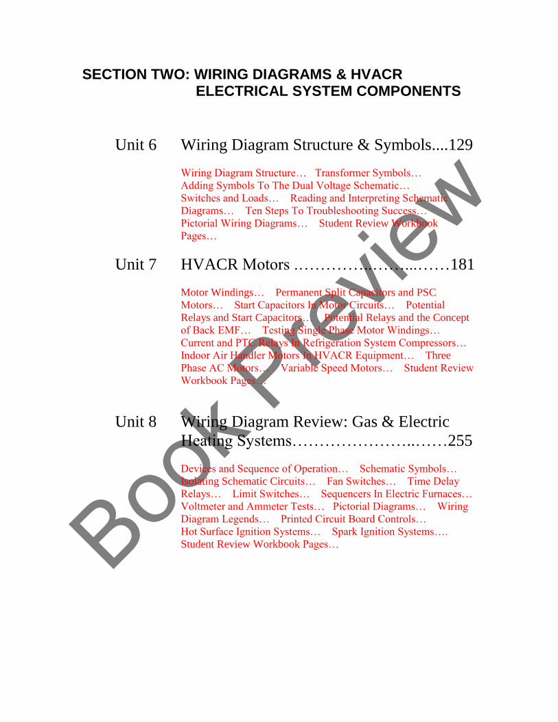
Unit 6 Wiring Diagram Structure & Symbols....129
Wiring Diagram Structure… Transformer Symbols…
Adding Symbols To The Dual Voltage Schematic…
Switches and Loads… Reading and Interpreting Schematic
Diagrams… Ten Steps To Troubleshooting Success…
Pictorial Wiring Diagrams… Student Review Workbook
Pages…
Unit 7 HVACR Motors .…………..……...……181
Motor Windings… Permanent Split Capacitors and PSC
Motors… Start Capacitors In Motor Circuits… Potential
Relays and Start Capacitors… Potential Relays and the Concept
of Back EMF… Testing Single Phase Motor Windings…
Current and PTC Relays In Refrigeration System Compressors…
Indoor Air Handler Motors In HVACR Equipment… Three
Phase AC Motors… Variable Speed Motors… Student Review
Workbook Pages…
Unit 8 Wiring Diagram Review: Gas & Electric
Heating Systems…………………..……255
Devices and Sequence of Operation… Schematic Symbols…
Isolating Schematic Circuits… Fan Switches… Time Delay
Relays… Limit Switches… Sequencers In Electric Furnaces…
Voltmeter and Ammeter Tests… Pictorial Diagrams… Wiring
Diagram Legends… Printed Circuit Board Controls…
Hot Surface Ignition Systems… Spark Ignition Systems….
Student Review Workbook Pages…
Book P
review
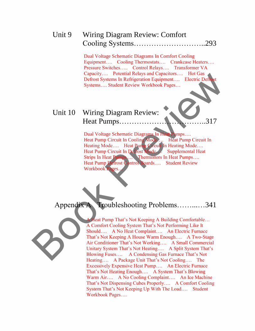
Unit 9 Wiring Diagram Review: Comfort
Cooling Systems………………………..293
Dual Voltage Schematic Diagrams In Comfort Cooling
Equipment…. Cooling Thermostats…. Crankcase Heaters….
Pressure Switches….. Control Relays…. Transformer VA
Capacity…. Potential Relays and Capacitors…. Hot Gas
Defrost Systems In Refrigeration Equipment…. Electric Defrost
Systems…. Student Review Workbook Pages…
Unit 10 Wiring Diagram Review:
Heat Pumps……………………………..317
Dual Voltage Schematic Diagrams In Heat Pumps….
Heat Pump Circuit In Cooling Mode…. Heat Pump Circuit In
Heating Mode…. Heat Pump Circuit In Heating Mode….
Heat Pump Circuit In Defrost Mode…. Supplemental Heat
Strips In Heat Pumps…. Thermistors In Heat Pumps….
Heat Pump Defrost Control Boards…. Student Review
Workbook Pages…
Appendix A Troubleshooting Problems……...…341 A Heat Pump That’s Not Keeping A Building Comfortable…
A Comfort Cooling System That’s Not Performing Like It
Should…. A No Heat Complaint…. An Electric Furnace
That’s Not Keeping A House Warm Enough…. A Two-Stage
Air Conditioner That’s Not Working…. A Small Commercial
Unitary System That’s Not Heating…. A Split System That’s
Blowing Fuses…. A Condensing Gas Furnace That’s Not
Heating…. A Package Unit That’s Not Cooling…. The
Excessively Expensive Heat Pump…. An Electric Furnace
That’s Not Heating Enough…. A System That’s Blowing
Warm Air…. A No Cooling Complaint…. An Ice Machine
That’s Not Dispensing Cubes Properly…. A Comfort Cooling
System That’s Not Keeping Up With The Load…. Student
Workbook Pages….
Book P
review
i
Foreword
A Note From The Author…
During my tenure as a trade school instructor, one of the modules I had the opportunity to
facilitate was Electrical Fundamentals, in which the students were brand new. Our daily
schedule was from 7:30 AM to 4 PM, and during morning classroom sessions we
followed the 50-minute military format, taking a ten-minute break every hour.
As we began our break time on the first day of class, I said:
“During the time we’ve been here in class this morning, someone in our city has bought
an electrical part that they don’t need, either due to technician error, dishonesty, or a
combination of those two things.”
It was a bold statement. And the reaction from my students was always surprise.
However, as any experienced instructor knows, at that point in a student’s study of
HVACR, with that deer-in-the-headlights look still fresh, and the aspect of the-authority-
at-the-front-of-the-room brand new, it wasn’t likely that I would experience any blow-
back from anything I said, even if somebody thought it was outrageous.
However, after a few days of working together with the group eight hours a day in our
50/50 classroom and lab session schedule, someone would inevitably work up the
courage to ask about what I had said when we took our first classroom break. And,
discussing some of the situations I had experienced in the field carried some weight on
the subject. But, when one of our graduates, some of whom had only been working for a
few months, came back for a visit and offered their input, it was much more convincing.
When asked about the idea of electrical troubleshooting mistakes being made between
7:30 and 8:20 in the morning, some said that they too had doubts about what they heard
on their first day in class. However, they discovered that due to a lack of understanding of
electrical concepts and the inability to correctly interpret wiring diagrams on the part of
some of those who showed up to service equipment, their customers would indeed often
wind up paying for parts they didn’t need.
Some of them also expressed doubt that it took that much time into the day for mistakes
to occur.
Jim Johnson
Book P
review
iii
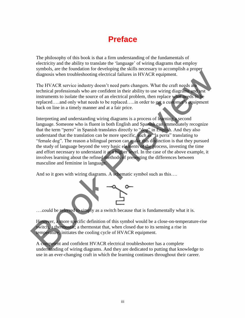
Preface
The philosophy of this book is that a firm understanding of the fundamentals of
electricity and the ability to translate the ‘language’ of wiring diagrams that employ
symbols, are the foundation for developing the skills necessary to accomplish a proper
diagnosis when troubleshooting electrical failures in HVACR equipment.
The HVACR service industry doesn’t need parts changers. What the craft needs are
technical professionals who are confident in their ability to use wiring diagrams and test
instruments to isolate the source of an electrical problem, then replace what needs to be
replaced…..and only what needs to be replaced…..in order to get a customer’s equipment
back on line in a timely manner and at a fair price.
Interpreting and understanding wiring diagrams is a process of learning a second
language. Someone who is fluent in both English and Spanish can immediately recognize
that the term “perro” in Spanish translates directly to “dog” in English. And they also
understand that the translation can be more specific, such as “la perra” translating to
“female dog”. The reason a bilingual person can make this distinction is that they pursued
the study of language beyond the very basic elements of the process, investing the time
and effort necessary to understand it at a higher level. In the case of the above example, it
involves learning about the refined methods of presenting the differences between
masculine and feminine in language.
And so it goes with wiring diagrams. A schematic symbol such as this….
….could be referred to simply as a switch because that is fundamentally what it is.
However, a more specific definition of this symbol would be a close-on-temperature-rise
switch, a thermostat; a thermostat that, when closed due to its sensing a rise in
temperature, initiates the cooling cycle of HVACR equipment.
A competent and confident HVACR electrical troubleshooter has a complete
understanding of wiring diagrams. And they are dedicated to putting that knowledge to
use in an ever-changing craft in which the learning continues throughout their career.

Book P
review
iv
________________________________________________ ACKNOWLEDGEMENTS When I wrote my first textbook, there were many people to thank, and one segment of the
dedication read “…to my wife Peggy Lee, who has been with me through all the ups and
downs and twists and turns of my personal and professional life for 25 years…” and, here
is the dedication for this book….
Dedication: To my wife Peggy Lee, who has been with me through all of the ups and downs and
twists and turns of my personal and professional life for 50 years.
Thanks To: Renee Tomlinson and Marlena Stavropoulos for their help in developing this updated
version of the original text; Simpson Electric, Fluke Corporation, and Fieldpiece
instruments for images from their user manuals; RSES Journal, Indoor Comfort News
and ACHR News readers who have helped in contributing to the development of
troubleshooting problems; and to the students in my trade school classes and technicians
who have attended my workshops and were not afraid to ask questions.

Book P
review
v
HVACR Troubleshooting Fundamentals Electricity and Wiring Diagrams
LIST OF ILLUSTRATIONS
UNIT
1
Generating Electricity & Electron Flow
Figure 1-1 Coal is chemical energy, which when burned becomes heat energy, which
generates steam energy, which becomes mechanical shaft energy to turn the generator,
which results in electrical energy.
Figure 1-2 High pressure steam contacting the blade of a turbine results in mechanical
energy that spins the shaft connected to the generator.
Figure 1-3 A permanent magnet showing the lines of force and the north and south poles
of a magnetic field.
Figure 1-4 An electromagnetic section of a generator. When magnetic lines of force are
cut by a conductor, a current is induced in the conductor.
Figure 1-5 A conductor is positioned so that it cuts the lines of force in the magnetic
field when the rotor of the generator spins.
Figure 1-6 This illustration shows an elementary atom. The neutron and proton combine
to form the nucleus of the atom, around which the electron is in orbit. As with the
principles of magnetism, a negative/positive concept applies in atomic theory, which is
also referred to as electron theory.
Figure 1-7 This illustration shows a silver atom. Because of its atomic structure, five
orbits of shells and a single outer shell electron, silver is an excellent conductor of the
electrical energy.
Figure 1-8 In the case of a good conductor of electricity, the single valence electron of a
material is easily knocked out of its orbit by the effect of a source of energy, such as
magnetism.
Book P
review
vi
Figure 1-9 A copper atom. Copper is a good conductor of electricity but not as efficient
as silver. Because of its atomic structure, containing only four orbits of atoms, it has less
energy than silver.
Figure 1-10 The atomic structure of an insulating material differs from that of a
conductive material. While conductor atoms have only one valence electron that is easily
knocked out of orbit, the atom of an insulator has up to 8 valence electrons.
Figure 1-11 Conductors, semiconductors, and insulators differ in their atomic structure.
A conductor atom (a) has only one valence electron, a semiconductor atom, (b) will have
up to 4 valence electrons, and an insulator atom, (c) contains up to 8 valence electrons.
Figure 1-12 The atomic structure of a material dictates whether it will be a good
conductor of electrical energy, or if it will be an effective insulator.
Book P
review
vii
UNIT
2
Alternating Current, Direct Current And
Electrical Power
Figure 2-1 As illustrated by the AC sine wave in this illustration, alternating current is
generated at 60 cycles per second in the United States. In Canada, in Europe, and in other
countries, the energy in alternating current will reach a positive and negative peak value
50 times per second, which means electricity is generated at 50 cycles.
Figure 2-2 A DC circuit showing a voltage, also known as potential difference, of 12
volts. The light bulb has a resistance of 6 Ohms. Using the proper Ohm’s Law formula
allows the calculation of the current draw (amperage) in the circuit.
Figure 2-3 When using an Ohm’s Law memory wheel such as the one shown here, cover
what you want to know, and the formula you need to use for the calculation will be
explained.
Figure 2-4 The electric furnace heating element in this example has a resistance of 12
ohms, and the applied voltage is 240 VAC. Using Ohm’s Law to calculate the current
draw of the element is the first step in determining what the cost of operating the element
will be.
Figure 2-5 One way to consider voltage as pressure in an electrical circuit is to compare
two water tanks that, although they have the same diameter flow pipe, the difference in
elevation causes one tank to be able to deliver flow at a higher pressure.
Book P
review
viii
UNIT
3
Electrical Distribution Systems
Single-Phase & Three-Phase Power
Figure 3-1 Electrical energy is generated at a high voltage level. This voltage is then
stepped up higher in order to transport it along high voltage transmission lines, which are
conductors that are not insulated. The voltage is then stepped down by a substation for
distribution to buildings.
Figure 3-2 An example of electromagnetism in which the conductor remains stationary
and the magnets are connected to the spinning shaft assembly.
Figure 3-3 Current flowing through a conductor results in an electromagnetic field
around the conductor.
Figure 3-4 In a step-up transformer, voltage is applied to the primary windings. The
electromagnetic field from the primary travels around the iron core, and when the larger
secondary windings pick up the electromagnetic field, the result is a higher output of
voltage.
Figure 3-5 In a step-down transformer, when voltage is applied to the primary windings
that have more turns than the secondary windings, the result is a lower voltage output.
Figure 3-6 The step-down transformer, in addition to being a segment of an electrical
generating system, is an integral component within HVACR equipment. Note the sine
wave, the symbol for alternating current generation, indicating voltage applied to the
primary windings. The symbol on the secondary windings indicates voltage output.
Figure 3-7 This illustration shows the typical layout of the components within a
distribution panel in a single-phase residential application. Since there are two power
(HOT) wires, it is referred to as a single-phase power supply.
Figure 3-8 Note the horizontal assemblies shown fastened to the buss bars in the open
space below the breakers. These attachments to the main buss bars in a distribution panel
allow breakers to be clipped into place. The two types of breakers found in residential
distribution panels are referred to as single-pole and double-pole breakers.
Book P
review
ix
Figure 3-9 Single-pole breakers are wired to a 120 VAC (Volts Alternating Current)
circuit and two-pole breakers are wired to a 240 VAC circuit. The “hot” legs of the
wiring are designated as L1 (L= Line) and L2. The designation “N” refers to the neutral
wiring in the panel.
Figure 3-10 A 120-volt receptacle that may be found in a gas furnace installation.
Figure 3-11 In a situation in which a gas furnace is connected to the circuit via a standard
power cord and the system uses a duplex receptacle, a load test can be conducted by
operating the furnace and simultaneously checking with a voltmeter.
Figure 3-12 To check for voltage drop in a single receptacle, a temporary adapter that
allows the furnace power cord to be connected to the circuit and also allows for checking
with a voltmeter can be employed to accomplish the test.
Figure 3-13 When checking with a voltmeter between the hot and the ground terminals
of a receptacle that is wired for proper polarity and ground, the reading will be 120 VAC.
Figure 3-14 When checking with a voltmeter between the neutral and the ground
terminals of a properly wired receptacle, your voltmeter should read 0 volts.
Figure 3-15 In the case of a 240-volt, single-phase condensing unit of a split system, a
two-pole breaker in the distribution panel is wired to an outdoor fused disconnect.
Figure 3-16 One style of fused disconnect used in HVACR installations is designed with
a pull-out fuse holder.
Figure 3-17 Testing for excessive voltage drop in a 240-volt circuit involves more than
the procedure for 120-volt circuits, beginning with checking at the L1 and L2 (Line 1 and
Line 2) connections as the wiring enters the fused disconnect, and on to the T1 and T2
(Terminal 1 and Terminal 2) connections on a component within the HVACR equipment
known as a contactor.
Figure 3-18 With the main breaker in the on position and the HVACR equipment
operating, checking for proper voltage begins with establishing a baseline voltage at the
wiring connections where the power is delivered into the distribution panel.
Figure 3-19 This illustration shows the two-pole breaker that is wired to the HVACR
equipment. Checking with a voltmeter at these test points will show the output voltage
from the panel.
Figure 3-20 When checking for voltage drop across the closed contacts of a contactor,
place one lead of the voltmeter on an L terminal and the other lead on a T terminal. The
meter will show a difference in potential across the terminals, which will be the amount
of voltage drop.
Book P
review
x
Figure 3-21 In the fundamental construction of a single-phase generator, a single
winding and a magnetic field are employed.
Figure 3-22 In the fundamental construction of a three-phase generator, three windings
and a magnetic field are employed.
Figure 3-23 The schematic symbol diagram for a Delta transformer system is shown at
the left and the pictorial diagram is at the right.
Figure 3-24 A schematic symbol diagram and a pictorial illustration of a Wye
transformer system.
Figure 3-25 A typical electrical distribution panel that can accommodate a three-pole
breaker for three phase HVACR equipment.
Book P
review
xi
UNIT
4
Electrical Supply Circuit Protection
Fuses & Circuit Breakers
Figure 4-1 Our magnifying glass shows that the alloy element of the fuse is unaffected
by the normal operation of the room air conditioning unit. Note that the fuse is shown in
the hot leg of the power supply to the receptacle. It is common to refer to the element in a
fuse as a fuse link or fusible link.
Figure 4-2 A short circuit in the power cord is causing a circuit overload and the fuse
link senses the over-temperature situation.
Figure 4-3 A broken fuse link shuts the equipment down.
Figure 4-4 The types of fuses shown here are (a) Edison Base (also referred to as a screw
type or plug type fuse), (b) Type S Plug fuse, (c) Type S Adapter, (d) Dual-element Plug
fuse, (e) Ferrule Type Cartridge fuse, and (f) Knife-Blade Cartridge fuse.
Figure 4-5 Circuit protection requirements are clearly marked on manufacturer
equipment tags.
Figure 4-6 In some installations a circuit breaker inside the building is the only
protection in the equipment circuit.
Figure 4-7 A fusible link may be positioned within the fuse, so an air barrier allows it to
fail safely. In some fuses, an arc-quenching material, such as silica sand, may surround
the link to prevent arcing when the fuse blows.
Figure 4-8 A three-phase fused disconnect switch. In order to ensure proper equipment
operation, all wiring connections must be tight and the clips that hold the fuses must be in
good condition. When removing fuses from a disconnect box the proper method is to use
a fuse puller rather than using a screwdriver to pry them loose.
Figure 4-9 A 240-volt, single-phase, disconnect with a pullout assembly that contains
two fuses. The fuse assembly is removed by gripping the handle in the center and pulling
straight out. The safety shield in the lower segment of the assembly can be removed
while leaving the fuse pull-out in place.
Book P
review
xii
Figure 4-10 In a typical 240-volt, single-phase fused disconnect assembly, the wiring
from the circuit breaker in the distribution panel is identified as Line 1 and Line 2 and the
wiring connections to the equipment are identified as Load 1 and Load 2. Note that in
addition to the hot wires in the box, there is a connection for ground.
Figure 4-11 Checking at the Line 1 and Line 2 connections in a disconnect assembly to
confirm 240-volts from the circuit breaker in the distribution panel.
Figure 4-12 Checking at the Load 1 and Load 2 connections in a pull-out, fused
disconnect assembly to confirm that the fuses are OK.
Figure 4-13 In a pull-out fused disconnect, the fuses are held in brass spring assemblies
that allow a connection between Line 1/Load1 and Line2/Load2 when the fuse holder is
in place.
Figure 4-14 Testing from one leg of the load side of the power supply to ground in a
fused disconnect box with the fuses in place will show 120-volts if the fuse is OK. If a
load to ground test shows 0-volts, the fuse is blown.
Figure 4-15 In a pull-out switch disconnect assembly, the handle is removed to kill the
power to the equipment.
Figure 4-16 The knife blade assemblies that bridge between the Line and Load segments
of the pull-out switch disconnect may be made of brass, or they may be copper coated
aluminum.
Figure 4-17 This illustration shows the openings for the knife blade switch and a
segment of the safety shield, which can be removed by pulling out on the plastic tab once
the switch assembly is pulled out.
Figure 4-18 In a pull-out switch type of disconnect, removing the switch allows for a
quick check to find out if power is applied to the assembly.
Figure 4-19 With the safety shield removed from a 240-volt, single-phase pull-out switch
disconnect box, the wiring connections are exposed. The Line connections are located in
the upper segment of the box, connected directly to one segment of the spring clips that
hold the pull-out switch. The Load connections are in the lower segment, connected to
fuse spring clips.
Figure 4-20 Fuses installed in a pull-out switch disconnect.
Figure 4-21 With the fuses in place, the safety shield removed, and the pull-out switch
inserted, testing to check if the fuses are responsible for equipment sitting dead can be
accomplished.
Book P
review
xiii
Figure 4-22 Testing from the left Load terminal in a pull-out switch disconnect assembly
to the ground terminal will prove whether the fuse is blown, or if it is OK.
Figure 4-23 Testing from the right Load terminal in a pull-out switch disconnect
assembly to the ground terminal will prove whether the fuse is blown, or if it is OK.
Figure 4-24 Installing an improper fuse can create a dangerous situation.
Figure 4-25 Due to improper fusing an overcurrent situation caused overheating and
damage to this pull-out switch disconnect box.
Figure 4-26 In this pull-out switch assembly, the Line connections are shown in the
center of the connector and Load connections are at the left and right. Note also the
ground connecting plug.
Figure 4-27 A two-pole breaker is used to provide a 240-volt, single phase power supply
to HVACR equipment. The switch in this example is shown in the ON position and the
distribution panel cover has been removed to show the wiring connections.

Book P
review
xiv
UNIT
5
Proper Use of Test Instruments
Figure 5-1 An analog meter operates on the principle of a pointer (often referred to as a
needle) moving and indicating a specific measurement. Image courtesy of Simpson
Electric.
Figure 5-2 An analog meter set to the R x 1 scale and ready to measure resistance on a
low scale. Connecting the meter leads to the COM and V/Ω ports shown at the bottom
right of the meter case will allow a component test for resistance. The top row of
numbers represents the ohms scale. Also note the ohms adjustment knob (ΩADJ) shown
at the left of the meter control section.
Figure 5-3 With the black lead connected to the COM port and the red lead connected to
the VΩ port, the pointer on the ohms scale is showing that the component under test has a
resistance of approximately 1 ohm.
Figure 5-4 When testing a switch for continuity (fundamentally no resistance) an analog
meter can be set for a more sensitive scale. The finest scale of measurement is commonly
the R x 10K scale. This scale is also an effective test of battery life. If the pointer won’t
adjust to 0 when the meter is set to a resistance scale, it’s likely that the battery needs to
be replaced.
Figure 5-5 The ohms adjustment knob has been used to set the pointer to 0 ohms. The
meter is now ready to test between the terminals of a closed switch to determine whether
the switch assembly has continuity.
Figure 5-6 A digital multi-meter set to measure resistance and continuity.
Figure 5-7 When the ohms setting is selected on this meter, other functions are available
at the same dial setting when the SELECT button of the meter on the meter is used to
toggle.
Figure 5-8 While experienced technicians have an overall understanding of the proper
use of test instruments, there is always a learning curve when using a particular model of
meter for the first time. This particular model of meter, in addition to accomplishing
electrical and temperature measurements, is capable of wireless communication to allow
data transfer to other specific devices.
Book P
review
xv
Figure 5-9 Manufacturer’s instruction manuals provide written instructions and
illustrations to explain the specific operation of a particular model of test device. This
image shows that one way to consider resistance and continuity tests of a load is that
setting the dial at a setting that will allow accurate measurement of a load that has
relatively high resistance. Choosing the continuity test setting will also determine
whether the load has failed open. Image courtesy of Fieldpiece Instruments
Figure 5-10 This illustration from a downloaded manual for a Fluke 16 multi-meter
shows resistance and continuity testing procedures.
Figure 5-11 The fundamental difference between potential voltage and applied voltage
must be understood when troubleshooting electrical problems in a circuit. Potential
voltage is available at the power source to equipment. Applied voltage refers to work
being done because energy is applied to a component that is doing the work.
Figure 5-12 With the selector knob set to the correct position and using the SELECT
button to toggle between the specific voltage settings available on this particular model of
test instrument, tests can be accomplished on hot circuits. Note the screen on the left
showing the sine wave, the symbol for alternating current. On the right screen, the solid
line with the dashed line below is the symbol for direct current.
Figure 5-13 When a meter employs a selection of range settings for voltage, the
technician needs to understand how to properly set the device in order to get accurate
information. Image courtesy of Fieldpiece Instruments.
Figure 5-14 In this example, the selector is set to a DC voltage setting and the chosen
range is 50 volts. Image courtesy of Fieldpiece Instruments.
Figure 5-15 When a digital meter reads AC voltage in what is commonly referred to as a
120-volt circuit, the accuracy of the device goes beyond the standard and measures the
voltage precisely.
Figure 5-16 A digital meter reading micro-amps to determine if an ignition system is
operating properly. Note the solid and dashed line in the upper right-hand corner of the
meter display, indicating direct current.
Figure 5-17 This meter is set to a micro-amp selection in order to measure the current
draw in the circuit. Image courtesy of Fieldpiece Instruments
Figure 5-18 In some troubleshooting situations, manufacturers may require testing of a
segment of a control circuit that involves checking the amperage in alternating current.
As this illustration shows, the device is set to the 200-milliamp scale in order to
accomplish a current draw check. Image courtesy of Fieldpiece Instruments
Book P
review
xvi
Figure 5-19 A spring loaded clamp that is positioned around the wire in a standard 240
or 120-volt AC circuit allows a technician to read the amperage draw of the circuit, or
isolate and check the amperage draw of a component within the equipment. Image
courtesy of Fieldpiece Instruments
Figure 5-20 When an amp clamp is placed properly, the wire is in the center of the
clamp, allowing the device to provide an accurate reading of the current draw through the
wire.
Figure 5-21 Some digital test instruments allow a measurement of amperage with the
connection of an amp clamp as an accessory. Always consult the manufacturer’s user
manual for specific instructions on how to attach accessories and choose the proper meter
settings in order to obtain accurate information.
Figure 5-22 When some devices are set specifically to check a capacitor, the display
screen will show the identifier µF for the procedure.
Figure 5-23 A meter set to check capacitance. Note that the selector knob is set to 20
MFD and the red lead has been removed from the VΩ port in order to be inserted into the
MFD port.
Figure 5-24 A meter set to check a diode. The correct setting on the ohms scale of the
device has been selected and the probes are used to check the diode. Note the electrical
symbol for the diode on both the face of the meter and the instruction from the
manufacturer’s user manual. Image courtesy of Fieldpiece Instruments
Figure 5-25 Some models of digital multi-meters can also be used to check temperature.
In this illustration a Type K thermocouple is attached to the meter, and the device is
showing 82.9° F.
Figure 5-26 When using a clamp type accessory and a digital meter to measure tubing
temperature, the surface of the tube should be clean to allow for an accurate
measurement.
Figure 5-27 Alligator clips can be used to ensure good connections during electrical
testing.
Figure 5-28 This illustration shows the difference in size between standard lead tips and
extended lead tips that allow for testing wire harness connectors (often referred to as
Molex connectors) without disconnecting the wiring. Extended leads are often coated
with carbon or other materials up to their sensing tip in order to prevent damage to
electronic control systems during certain diagnostic testing procedures.
Figure 5-29 This illustration shows one manufacturer’s method of accessing the battery
compartment located on the back side of a digital meter.

Book P
review
xvii
Figure 5-30 The chemical make-up of a battery will cause it to corrode over time. When
the test device containing this battery was inspected after a long storage time frame
exposed to extreme elements, there was significant damage to the electronic components
of the meter.
Figure 5-31 Disassembly of the case of a digital meter exposes the operating components
of the device. Always handle carefully and avoid touching the printed circuit board
components of the meter. Note the location of two fuses in this particular example shown
on the two sides of the case near the bottom.
Book P
review
xviii
UNIT
6
Wiring Diagrams &
HVACR System Components
Figure 6-1 A schematic symbol for a step-down transformer used in HVACR electrical
systems. The two voltage systems that exist in equipment are operating voltage and
control voltage. The control voltage is 24 VAC and the operating voltage can be 120
VAC, 240 VAC or 480 VAC.
Figure 6-2 The fundamental dual voltage schematic diagram is built on the symbol of the
transformer. With lines added to the symbol from both windings, other symbols
representing loads and switches can be shown in the appropriate location on the diagram
with the connecting lines drawn from these component symbols to the extended lines on
the transformer symbol.
Figure 6-3 A step-down transformer with a 120 VAC primary (indicated by the black
and white wire color code) and a 24 VAC secondary. In this example the manufacturer is
using red and green to show the output wiring connections. The color green in this case is
not an indication of a ground connection. Manufacturers use a variety of colors to
indicate the 24-volt connections of a transformer.
Figure 6-4 In this example, the voltage input is identified as L1 and L2 (Line 1 and Line
2) and connected to PR1 and PR2 (Primary). The output voltage of 24 VAC is delivered
from the SEC1 and SEC2 (Secondary) connections of the transformer.
Figure 6-5 In this example, a temporary wiring connection has been accomplished to the
primary winding of a transformer. This particular transformer is designed for use in a
situation in which the equipment voltage is 120 VAC, and the meter shows the proper
voltage is being applied to the primary connections.
Figure 6-6 In order to either confirm or eliminate the transformer as the possible source
for a “sitting dead” complaint, once a voltage test proves that the proper voltage is
applied to the primary winding, a test of the secondary winding connections is
accomplished to measure the output voltage.
Figure 6-7 With a meter set to the proper scale relative to Ohms, testing the primary
winding of a transformer will provide an accurate measurement of resistance.
Book P
review
xix
Figure 6-8 The resistance of the secondary winding of this transformer is 3.3 Ω.
Figure 6-9 The secondary winding of this transformer has failed. The meter display is
showing “OL” which is an indicator of “Open Line”.
Figure 6-10 A pictorial illustration of a transformer that shows the relationship between
the primary and secondary winding of the transformer as being related only to the
concept of an electromagnetic field set up by current flow through a winding.
Figure 6-11 An example of a schematic diagram that is built on the symbol of the
transformer, and showing switches, loads, and the circuits of the equipment. Loads are
identified by the letter “L”. Switches are identified by the letter “S”. Two other
components shown here are capacitors, identified as “CAP”. In our example, they are not
strictly considered to be a load or a switch.
Figure 6-12 One example of a schematic diagram that uses abbreviations to identify the
loads and switches in the equipment. An abbreviation that one manufacturer may use for
a particular component will often not be the identical one used by a different
manufacturer for the same component.
Figure 6-13 A contactor is a device used to control the operation of a compressor. The
switching segment of the device is wired in series with the compressor motor. The coil is
operated on control voltage.
Figure 6-14 One common method of controlling the operation of a compressor is to
allow the equipment voltage to pass through the equipment voltage switching assembly
when 24 volts is applied to the operating coil of the contactor, causing the switch contacts
to close.
Figure 6-15 “L” on contactor connections stands for “Line”. “T” on contactor
connections stands for “Terminal”. When a contactor is wired correctly, power input is at
the Line connections. Power output is at the Terminal connections when the contactor
coil is energized, closing the contact and spring assembly.
Figure 6-16 The resistance of this coil is approximately 12 Ohms, which is typical of this
type of component. If the meter showed “OL” with this test, the coil would be open and
the contactor would have to be replaced.
Figure 6-17 One example of diagram showing only one set of contacts while the
component may actually have more than one switch, is a fan relay. In this example, the
coil and one set of contacts in the relay are being used to control the indoor fan motor.
Figure 6-18 A typical relay that has been used for decades in the HVACR industry to
control the operation of an indoor air handler motor, as well as other applications in
equipment operation.
Book P
review
xx
Figure 6-19 This relay has eight terminal connections. Two of the connections are for the
operation of the coil while the other connecting terminals provide a connection to the
switching circuits of the device. “COM” is an identifier for what is known as a common
terminal on the device.
Figure 6-20 Upon closer inspection of a relay such as this found in HVACR equipment,
technicians can find information about the coil operating voltage and manufacturer’s
identifying numbers.
Figure 6-21 With the wiring disconnected from the terminals of the relay coil, the leads
of an ohmmeter are attached as shown here to measure the resistance of the coil.
Figure 6-22 The result of our coil test in this case is 15.8 Ω resistance, which is typical
for this type of relay coil if it is OK.
Figure 6-23 Checking N.O. terminals of a relay to determine that they are, in fact, open
without voltage applied to the coil.
Figure 6-24 Testing at the N.O. terminals on a relay should show “Open Line” without
control voltage applied to the relay coil.
Figure 6-25 If the N.O. relay contacts are in good condition, the meter will display a very
low resistance when voltage is applied to the relay coil. In the event that the meter
showed 1 Ohm resistance or more, it would indicate that the contacts are corroded, and
would cause excessive voltage drop in the circuit.
Figure 6-26 Testing the N.C. contacts of a relay without control voltage applied to the
coil should show a very low resistance on the meter display.
Figure 6-27 Tracing a circuit from source to source. Beginning at L1 on the diagram,
then tracing through the load, and all the way through the circuit to L2, simplifies the
concept of current flow in a circuit through a load.
Figure 6-28 Tracing both the equipment and control voltage circuits to understand the
operation of a component that is only energized with equipment voltage when control
voltage is applied to the coil of the device, causing the equipment segment of the device
to close and allow a complete circuit to the operating component.
Figure 6-29 When this equipment is operating, all of the equipment voltage components
are operating due to a call for cooling by the thermostat.
Figure 6-30 In this illustration, the crankcase heater and the transformer primary show
applied voltage. All the other circuits involved in the sequence of operation of the
equipment show potential voltage.
Book P
review
xxi
Figure 6-31 From a schematic standpoint, potential voltage can be read at SEC1 and
SEC2, as well as at the power-in switch of thermostat assembly and at the direct wiring
connections from SEC2 on both the indoor fan relay coil and contactor coil. However,
from a practical standpoint, checking for potential voltage at the operating coils would be
accomplished by checking at SEC1 and at the direct wire connections on the coils.
Figure 6-32 With the thermostat system switch, temperature switch, and fan switch in
closed positions, the potential voltage is now applied to the indoor fan relay coil and
contactor coil.
Figure 6-33 With no call for cooling from the thermostat, the two circuits on our
schematic that would show applied voltage at test points A and B are the crankcase heater
and primary of the transformer.
Figure 6-34 When there is a call for cooling from the thermostat and the indoor fan relay
and contactor coils are energized, the contacts of the contactor and the switching contacts
in the indoor fan relay are designed to close. This process allows voltage to be applied to
the compressor, condenser fan motor and indoor fan motor.
Figure 6-35 A run capacitor is wired in a motor circuit in series with the start winding.
Understanding this fact helps in identifying the windings of the motor in this example.
This illustration shows the path of current flow from L1, through the start winding of the
motor, and back to L2. When a motor of this type is fully operational, there will be
current flow through both windings.
Figure 6-36 A pictorial diagram provides some insight on where some components in the
equipment are located and how wiring connections are accomplished. Pictorial diagrams
often show wiring harness color code. This example also shows that the manufacturer is
using a number/letter method of identifying the components, information that would also
appear on a legend accompanying the diagram.
Figure 6-37 A segment of a pictorial diagram that illustrates the operation of an
electronic time delay relay. The transformer secondary is shown schematically, while the
other components and the wiring harness are shown from a pictorial perspective.
Figure 6-38 This electronic time delay relay is one example of a Delay-On-Break device
that may be used in a gas furnace system to delay the shut-down of the indoor air handler
motor.
Book P
review
xxii
UNIT
7
HVACR Motors
Figure 7-1 A simplified illustration of an AC (Alternating Current) electric motor
operating through one complete rotation. Note the S and N designations for South and
North poles of the magnets. The permanent magnet known as the rotor is mounted in a
bearing assembly at each end of the motor and rotates due to the push/pull of the
magnetic fields.
Figure 7-2 The run windings of this motor are identified as the A windings and the start
windings are the B windings. Also shown here is a fundamental fact regarding the
difference between start and run windings in a motor; that the start winding will have
more turns than the run winding.
Figure 7-3 An example of a PSC motor circuit. Understanding how to troubleshoot this
these components begins with understanding what are, and are not, connecting points on
the diagram.
Figure 7-4 Tracing a circuit from L1, on through the motor run winding to common, and
then to L2 shows the flow of current through the run winding when the circuit is
energized.
Figure 7-5 Tracing a circuit from L1, on through the run capacitor and motor start
winding to common, and then back to L2, shows the flow of current when the start
winding is energized.
Figure 7-6 In a motor that does not use a run capacitor to implement a PSC system, when
the motor is running after the instant of start, the run winding electromagnetic field only
accomplishes the movement of the rotor.
Figure 7-7 In a PSC operation, both the run and start windings provide a “bump” for the
rotor, resulting in a more efficient operation of the motor.
Figure 7-8 In this schematic representation of a PSC circuit, the individual circuits for
the run and the start winding can be traced from source to source.
Figure 7-9 A motor run capacitor is constructed of foil plates that allow for the storage of
electricity up to a given level until it is discharged.
Book P
review
xxiii
Figure 7-10 This run capacitor has a rating of 10 microfarads and has a voltage rating of
370 to 440 VAC. When repairing equipment with a failed run capacitor, the best rule to
follow in the field is to use an exact replacement. In some situations, a manufacturer may
indicate a + or – 10% listing on a capacitor label, or the listing may show + 10% and –
5%.
Figure 7-11 An example of a dual run capacitor that may be found in equipment that has
been in service for an extended period of time. In these instances, rust and corrosion
make it difficult to read the terminal markings on a capacitor manufactured with a metal
case.
Figure 7-12 This capacitor label is still legible. We can determine that the capacitor for
the compressor is 60 MFD and the capacitor for the outdoor fan motor is 5 MFD. The
capacitor in this example is in a metal case. In some situations, you will find run
capacitors in a plastic case.
Figure 7-13 This run capacitor label shows a basic diagram for a dual capacitor,
identifying the black terminal as common, the white terminal as the compressor
connection, and the green terminal as the outdoor fan motor connection.
Figure 7-14 Here, a check with a digital meter shows that the FAN segment of this dual
capacitor has failed, specifically that it is open.
Figure 7-15 A check with a digital meter shows that the HERM segment of this dual
capacitor is weakening due to age. It has a 60 MFD rating, and the meter display is
showing 54.4 MFD.
Figure 7-16 When checking components for proper value, a good practice to follow is to
use meter leads with alligator clip extensions in order to ensure an accurate reading.
Figure 7-17 Our meter display shows that the 10 MFD capacitor under test is OK. In the
event that a run capacitor is holding a charge and test instrument leads are connected, the
display on the screen will be delayed, or in some cases the meter may show “Disc” to
indicate it is discharging the capacitor prior to reading the microfarad value.
Figure 7-18 This start capacitor is rated from 189 to 227 microfarads. Its operating
voltage range is 250 VAC. Start capacitors are manufactured in plastic cases.
Figure 7-19 Start capacitors, like run capacitors, employ foil plates to temporarily store
electrons before discharging them. Unlike run capacitors that are oil-filled, start
capacitors contain an electrolytic fluid.
Figure 7-20 A pop-out hole will release gasses that could build up if a start capacitor
overheats due to being in a circuit longer than it is designed to be.
Book P
review
xxiv
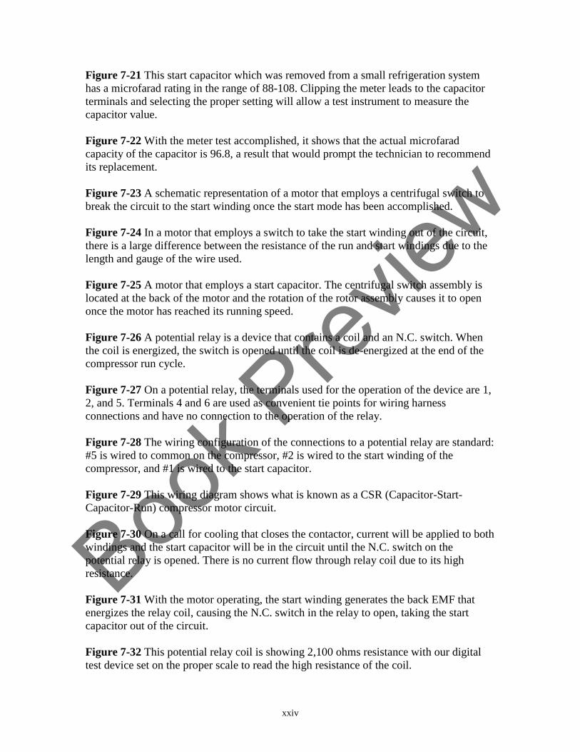
Figure 7-21 This start capacitor which was removed from a small refrigeration system
has a microfarad rating in the range of 88-108. Clipping the meter leads to the capacitor
terminals and selecting the proper setting will allow a test instrument to measure the
capacitor value.
Figure 7-22 With the meter test accomplished, it shows that the actual microfarad
capacity of the capacitor is 96.8, a result that would prompt the technician to recommend
its replacement.
Figure 7-23 A schematic representation of a motor that employs a centrifugal switch to
break the circuit to the start winding once the start mode has been accomplished.
Figure 7-24 In a motor that employs a switch to take the start winding out of the circuit,
there is a large difference between the resistance of the run and start windings due to the
length and gauge of the wire used.
Figure 7-25 A motor that employs a start capacitor. The centrifugal switch assembly is
located at the back of the motor and the rotation of the rotor assembly causes it to open
once the motor has reached its running speed.
Figure 7-26 A potential relay is a device that contains a coil and an N.C. switch. When
the coil is energized, the switch is opened until the coil is de-energized at the end of the
compressor run cycle.
Figure 7-27 On a potential relay, the terminals used for the operation of the device are 1,
2, and 5. Terminals 4 and 6 are used as convenient tie points for wiring harness
connections and have no connection to the operation of the relay.
Figure 7-28 The wiring configuration of the connections to a potential relay are standard:
#5 is wired to common on the compressor, #2 is wired to the start winding of the
compressor, and #1 is wired to the start capacitor.
Figure 7-29 This wiring diagram shows what is known as a CSR (Capacitor-Start-
Capacitor-Run) compressor motor circuit.
Figure 7-30 On a call for cooling that closes the contactor, current will be applied to both
windings and the start capacitor will be in the circuit until the N.C. switch on the
potential relay is opened. There is no current flow through relay coil due to its high
resistance.
Figure 7-31 With the motor operating, the start winding generates the back EMF that
energizes the relay coil, causing the N.C. switch in the relay to open, taking the start
capacitor out of the circuit.
Figure 7-32 This potential relay coil is showing 2,100 ohms resistance with our digital
test device set on the proper scale to read the high resistance of the coil.
Book P
review
xxv
Figure 7-33 When testing a potential relay coil that has failed, a properly set test
instrument will show “OL” indicating that the coil has no resistance.
Figure 7-34 Testing between terminals 1 and 2 on the potential relay to determine if the
switch is OK, or if it has failed.
Figure 7-35 When testing the switch segment of a potential relay with an ohmmeter and
the display shows a fraction of an ohm, the switch is considered to be in good condition.
Figure 7-36 Testing with an ohmmeter between the C (Common) and R (Run) terminals
will check the resistance of the run winding. Testing between the C and S (Start)
terminals will check the resistance of the start winding.
Figure 7-37 When testing PSC compressor motor windings, the difference between the
resistance of the windings will often be slight.
Figure 7-38 Fractional horsepower refrigeration system compressors often employ a
current relay to accomplish compressor motor starting. It is an electromechanical device.
Figure 7-39 An internal overload protector on a small refrigeration system compressor is
held in place by a clip, enabling it to sense the compressor dome temperature. In some
cases, external overload protectors may also be designed to sense current draw.
Figure 7-40 A schematic representation of a current relay and compressor terminals
shows that the coil of the relay is wired in series with the run winding and the switch
assembly is wired in series with the start winding.
Figure 7-41 A start capacitor is also sometimes employed in a current relay motor
circuit. It is also common for some manufacturers to use the letter “M” (Main) to identify
the run winding of the compressor on their diagrams.
Figure 7-42 Confirming that power is applied to the relay and the inlet of the overload
protector.
Figure 7-43 After confirming power applied to the inlet of the overload protector, O-
volts measured at the outlet of the overload protector proves that it has failed, preventing
the motor from attempting a start.
Figure 7-44 A compressor test cord that connects to a 120-volt power supply and allows
for connecting directly to the compressor terminals allows a technician to start the
compressor and use an ammeter to check its current draw.
Figure 7-45 A solid state device known as a PTC (Positive Temperature Coefficient)
relay is used in small refrigeration systems.

Book P
review
xxvi
Figure 7-46 A schematic representation of a PTC relay, run capacitor, and compressor
circuit. The schematic symbol within the PTC relay indicates that it is a resistor that
increases in resistance as the temperature increases.
Figure 7-47 In a PTC relay circuit at the instant of start, the path of current flow is
through the relay resistor.
Figure 7-48 In the run mode, the PTC device maintains a high resistance and the path of
current flow is through the run capacitor, creating the PSC motor circuit.
Figure 7-49 A 3-speed PSC operated motor is one that is typically found in HVACR
equipment that employs a gas or electric heating system along with a refrigeration system
for the cooling mode.
Figure 7-50 The path of current flow to operate a multiple speed motor on high speed is
shown here. In addition to the high-speed winding, the start winding is also energized. If
the equipment operation called for the motor to operate on medium or low speed, L1
would be routed through those connections instead of the high-speed winding.
Figure 7-51 When working with 120-volt multiple speed motors, the most common color
code used for the start, common, high, and low speed connections are shown.
Figure 7-52 A multiple speed air handler motor is controlled by a relay assembly
integrated into a printed circuit board control that switches the circuit in order to operate
the motor in the selected mode of equipment operation. The equipment in this example
has a gas heat system.
Figure 7-53 A segment from a pictorial diagram showing a 4-speed indoor air handling
motor and the control relay assembly on a printed circuit board.
Figure 7-54 An ohmmeter check showing an open motor winding. With the wiring
harness disconnected, checking with an ohmmeter should show resistance when testing a
motor winding.
Figure 7-55 Using a clamp type ammeter around the appropriate wiring connection, an
operating motor can be checked for proper current draw.
Figure 7-56 A standard 3-phase A/C motor has 3 separate windings to propel the rotor.
Figure 7-57 This schematic diagram shows the wiring connections for a Delta three-
phase motor designed to operate on a low or high voltage, specifically 240 VAC or 480
VAC.
Figure 7-58 A six-winding, three-phase motor shown in a Wye configuration.
Book P
review
xxvii
Figure 7-59 This motor is wired for 240 VAC operation. In three-phase motors of this
type, while the control device line side connections are identified as L1, L2, and L3 as
with single-phase contactors, the terminal side connections of a magnetic starter may be
identified as C1, C2, and C3.
Figure 7-60 This motor is wired for 480 VAC operation.
Figure 7-61 In this example L1 is wired to winding A, L2 is wired to winding B, and L3
is wired to winding C, and the motor is rotating clockwise.
Figure 7-62 By reversing the L1 and L2 leads connected to the motor, the rotation of the
motor is changed to a counter-clockwise direction.
Figure 7-63 An example of variable speed technology employed in the operation of a
refrigeration system compressor. The equipment power supply is 120 VAC. The
compressor is three-phase and operates on DC voltage.
Figure 7-64 Specific information from a manufacturer’s troubleshooting guide that
shows test points and the voltages that should be read if the electronic control system is
operating properly.
Figure 7-65 An NTC device designed to sense temperature and send information to a
variable speed compressor control board will often employ a quick connect for the wiring
harness. The sensor may be positioned to sense air flow, or it may be clipped to a
segment of refrigeration system tubing.
Figure 7-66 An NTC thermistor may be designed with a clip that will allow it to sense a
segment of refrigerant system tubing and send that information to the compressor control
board.
Figure 7-67 An example of a manufacturer’s chart that shows what the resistance of a
certain NTC thermistor should be at a given temperature.
Figure 7-68 One example of a variable speed motor that has a separate control section
attached to the motor case. This motor is used as a drop-in replacement for a standard
PSC direct drive motor and can be wired for clockwise or counterclockwise rotation. It
also operates on both 115 and 230 VAC. When it is employed in a 115 VAC power
supply system, a jumper wire is installed behind the access door shown on the brain
segment of the assembly.
Figure 7-69 The wiring connections to an OEM ECM are accomplished with two
harnesses connected to the motor assembly. A 5-pin connector is for the operating power
supply, and a 16-pin connector allows for the connection of the control assembly wiring
harness.
Book P
review
xxviii
Figure 7-70 When a constant flow ECM is wired to operate on 120 VAC, terminal #3 is
Ground (G), terminal #4 is Neutral (N), and terminal #5 is hot (L1). A jumper wire is
installed between terminals 1 and 2 to allow the motor to operate on 120 VAC.
Figure 7-71 One example of a manufacturer-specific test device used in troubleshooting
an ECM. By disconnecting the control harness from the motor and replacing with the
harness of the test device, then connecting the alligator clips of the device to a 24-volt
power supply, the test device can be turned on to check the operation of the motor.
(Image courtesy of Regal Beloit)
Figure 7-72 Depending on the specific version of an ECM, a test device of a different
specific design may be used in the troubleshooting process.
Figure 7-73 When a constant flow ECM is wired to operate on 240 VAC, terminal #3 is
Ground, terminal #5 is L1 and terminal #4 is L2. Terminals #1 and #2 are not connected
via a jumper wire when the motor is operated on 240-volts.
Figure 7-74 Once the power to the equipment has been off for at least five minutes, it is
safe to remove the screws and separate the control from the motor case.
Figure 7-75 This ECM control has two high voltage capacitors that could cause serious
injury if a technician doesn’t wait at least 5 minutes to allow them to discharge before
removing the control segment from the motor assembly. The motor wiring harness
disconnect is also shown here.
Figure 7-76 With a test instrument set properly, the windings of an ECM motor can be
checked for resistance. Here our meter shows 5.5 Ω.
Figure 7-77 This test from a motor lead to the motor case shows that the motor winding
is not shorted to ground. If the motor was grounded, the meter would show continuity.
Figure 7-78 A single speed ECM Outdoor Fan Motor that employs a separate control
board.
Figure 7-79 Checking for control voltage at a two-speed outdoor control board is
accomplished by testing between common and either of the 24 VAC connections.
Figure 7-80 In the case of a PWM operated outdoor fan motor, AC operating voltage for
the motor is checked at L1 and L2, and the DC control voltage measurements are
accomplished at PWM1 and PWM2.
Book P
review
xxix
UNIT
8
Wiring Diagram Review Gas & Electric Furnaces
Figure 8-1 The gas furnace represented in this schematic diagram does not have an
electronic control system, spark or hot surface ignition system, or induced draft system.
Figure 8-2 Identifying the assemblies related to the operation of a gas furnace helps in
interpreting the schematic diagram. Considering the view shown here, it is understood
that the Disconnect Switch Assembly and Thermostat Assembly, while they are shown as
part of the schematic, they are wall-mounted, remote, relative to the furnace cabinet. The
Fan/Limit Switch Assembly and the other components shown are located in the furnace
cabinet.
Figure 8-3 The electrical system in this gas furnace is ready to operate, waiting on a call
from the thermostat to initiate a cycle of operation. The hot leg of the 120 VAC power
supply is shown in red and neutral is blue. The 24- VAC power supply is shown in
yellow.
Figure 8-4 When the thermostat closes on a call for heat, there is current flow through
the gas valve solenoid, resulting in the opening of the valve, allowing gas flow to the
burners to be ignited by the standing pilot.
Figure 8-5 With the gas burners operating, the fan switch reacts to the temperature rise in
the heat exchanger and closes. As a result, there is a complete circuit to the indoor fan
motor.
Figure 8-6 Until the temperature in the room reaches the thermostat set-point, all the
circuits in the furnace are complete.
Figure 8-7 In this schematic, a time delay relay is used to control the operation of the
indoor blower motor. In the event that the limit switch opens in an over-temperature
situation, it also operates the indoor blower motor.
Figure 8-8 Conducting voltage tests at the points where 24 volts is supposed to be
applied, and in the 120-Volt blower motor circuit, will confirm the condition of the time
delay relay. The 120-volt switch check is testing from one switch terminal back to the hot
leg of power, and through the motor winding back to the neutral side of the circuit.
Book P
review
xxx
Figure 8-9 The terminals identified with the letter H are the connections to the heating
element in the relay. Terminals 2 and 4 in this example are wired to the relay switch
contacts.
Figure 8-10 In electric heating systems a sequencer is used to make and break circuits to
heating elements in steps. In addition to the “H” terminals that are wired to the 24-volt
heating segment of the device, a sequencer has at least two sets of switching contacts.
Figure 8-11 The switching terminals of this sequencer are identified as “M” connections.
The 24-volt heating segment of the device is connected to the un-marked brass terminals
shown at the bottom. A device such as this is designed to energize two heating elements
in sequence.
Figure 8-12 This illustration shows one example of M terminals that would be wired in
series with a heating element, which is a high current draw device, and the A terminals
that would be wired in series with another sequencer’s control segment, which is a very
low current draw device.
Figure 8-13 In some electric furnaces a sequencing timing device may control a heating
element along with indoor blower motor operation, and also have an auxiliary contact
that will close to energize a second sequencer.
Figure 8-14 This wiring diagram shows the schematic symbols used to illustrate the
circuitry in an electric furnace.
Figure 8-15 When the thermostat calls for heat, a 24-volt circuit through the Fan Control
and Sequencer #1 is complete and the resistance coils in those components begin the
process of providing heat to close contacts on the equipment voltage segment of the
circuit that are wired in series with the heating element and indoor blower motor.
Figure 8-16 Upon an initial call for heat, one heating element and the indoor fan motor
are operating. This illustration also shows the complete circuit through the primary
winding of the transformer that is present whenever power is applied to the equipment.
Figure 8-17 When the resistor coil of SEQ #2 is energized, the M1 M2 contacts will
close to complete a circuit to the second heating element. If necessary, the continued call
for heat will energize the resistor coil in subsequent sequencers, causing all the heating
elements to be energized.
Figure 8-18 Performing a voltage and amp draw check on an individual heating element
will determine whether or not it is providing heat.
Figure 8-19 An example of a P.C. board control system for a gas furnace. (Image
courtesy of Carrier Corporation)

Book P
review
xxxi
Figure 8-20 A pictorial diagram provides an alternate view of the printed circuit board
control system of a gas furnace. (Image courtesy of Carrier Corporation)
Figure 8-21 A legend explains the component identifiers that are abbreviated on
schematic and pictorial diagrams. (Image courtesy of Carrier Corporation)
Figure 8-22 Equipment notes that accompany the schematic and pictorial diagram
provide information about the equipment installation and other factors regarding the
operation of the electrical system. (Image courtesy of Carrier Corporation)
Figure 8-23 In the case of this printed circuit board control, the manufacturer’s
troubleshooting information would include written instructions for accomplishing voltage
tests at specific points.
Figure 8-24 An example of components such as a fuse, control relays, and dip switches
that are shown schematically and are located on the printed circuit board.
Figure 8-25 An example of a fuse that is removed from a printed circuit board for testing
with an ohmmeter.
Figure 8-26 A gas furnace limit switch that may be referred to as a thermo-disc type of
switch.
Figure 8-27 In this schematic diagram, the limit switch is identified as component # 7H.
Switches of this type may react to excessive temperature, open, then re-set when they
cool down, or they may be referred to as a one-time limit switch because once they open,
they don’t re-set. In this specific case, it is a one-time switch. Also shown wired in series
with the secondary of the transformer is a fuse (# 11C).
Figure 8-28 The 2F relay on this board is used in the event that the furnace is an air
handler in a heat/cool application, operating the fan on high speed for the cooling mode.
The 2A relay is used for time delay operation of the blower motor in the heating mode.
The protective fuse can be removed to be checked with an ohmmeter.
Figure 8-29 A segment of a pictorial diagram that shows an N.O. pressure switch. When
the switch reacts to the positive pressure in the furnace vent system, it closes allowing the
sequence of operation to continue.
Figure 8-30 A pressure switch assembly contains an N.O. switch mounted to a bellows
assembly. Pressure hose connections from the switch to the vent system allow the device
to sense the pressure in the vent to close the switch and allow an ignition system circuit.
Figure 8-31 In this pictorial diagram, the 24 VAC Spark Electrode operates on a call for
heat when the N.C. switch in the Pilot allows the circuit for the spark to ignite the pilot
flame. An N.O. switch in the pilot assembly allows the gas valve to open once the pilot is
proven.
Book P
review
xxxii
Figure 8-32 When a flame sensing rod is operating properly, it sends a message to the
ignition control system that the flame is present, allowing the gas valve to remain open
and continue the sequence of operation of the equipment. The ignitor in this example
operates on 24 VAC.
Figure 8-33 A control module, gas valve, ignitor and flame sensing rod.
Figure 8-34 In a direct spark ignition system, the spark electrode ignites the main burner
directly on a call for heat from the thermostat.
Book P
review
xxxiii
UNIT
9
Wiring Diagram Review Comfort Cooling & Refrigeration Systems
Figure 9-1 A simplified dual-voltage schematic diagram for a comfort cooling system
without legend identifiers.
Figure 9-2 This illustration shows a dual-voltage schematic for a comfort cooling system
with legend identifiers. Color coding for the thermostat wiring is also shown: R
(Red=Voltage into the thermostat, G (Green=Wiring to Fan Relay Coil) Y
(Yellow=Wiring to Contactor Coil…Cooling).
Figure 9-3 In some cases protective switches are wired in series with the contactor coil,
but in the equipment voltage circuit. When this method of operation is employed a
Control Relay (CR) makes and breaks the circuit to the contactor coil via a set of N.O
contacts. Also in the CR are a set of N.C. contacts wired in series with the Crankcase
Heater (CH).
Figure 9-4 An external crankcase heater is designed with an adjustable clamp and is
fastened near the bottom of the compressor.
Figure 9-5 A crankcase heater that is inserted into a tubing cavity (Heating Element
Encasement) in the compressor.
Figure 9-6 This diagram represents a small package unit air conditioner manufactured by
York International Corporation. In addition to symbols and the legend, the individual
wires are numbered, and the wire harness color code is shown.
Figure 9-7 The simplest form of a control thermostat is a bi-metal strip consisting of two
dissimilar metals that, when reacting to temperature change, warp and make or break a
set of contacts.
Figure 9-8 In this design of electromechanical thermostat, the bi-metal strip warps to
change the position of the mercury bulb. The mercury inside the bulb makes and breaks
the 24-volt power source to operate contactor coils and relays.
Figure 9-9 This example of a typical digital thermostat sub-base shows where the field
wiring is connected to the screw terminal connections, and the pin connections that allow
for connecting the thermostat body to the sub-base.
Book P
review
xxxiv
Figure 9-10 This illustration shows a segment of a digital thermostat and the connecting
pins on the thermostat body that allow it to be connect to the sub-base.
Figure 9-11 One example of a digital thermostat that allows for energy saving
programming in a cooling/heating application.
Figure 9-12 This illustration shows a low voltage wiring harness connected to a
thermostat sub-base (Red=Voltage, Yellow=Cooling, White=Heating, Green=Fan) for
one type of heating/cooling application. In the event that this device is used in other
applications, such as a heat pump, additional wires in the harness would be connected to
other terminals on the sub-base.
Figure 9-13 The terminal wiring connections on the equipment printed circuit board
allow for connection of the low voltage control wiring harness. When the wiring harness
is removed, jumpers can be installed on the appropriate wiring connections to eliminate
the thermostat and the wiring from the equipment to the thermostat and operate the
equipment manually.
Figure 9-14 In this partial wiring diagram, the compressor windings are shown along
with the potential relay. Also note the optional run capacitor that would allow this
compressor motor to operate as PSC.
Figure 9-15 A partial diagram from a comfort cooling system that shows another
example of identifying the potential relay in a compressor circuit. The switch of the relay
is shown as being wired between terminals 1 and 2, and the coil is shown wired between
terminals 2 and 5.
Figure 9-16 This illustration shows the electrical system that employs a hot gas solenoid
valve and timer to accomplish defrost in a commercial reach-in refrigerator.
Figure 9-17 One example of a defrost timer that controls the operation of an electric
defrost system in a commercial reach-in refrigerator.
Book P
review
xxxv
UNIT
10
Wiring Diagram Review Heat Pumps
Figure 10-1 A simplified dual-voltage schematic diagram of a packaged unit heat pump
showing symbols and circuits without legend identifiers.
Figure 10-2 A separate diagram that shows a supplemental heat segment in heat pump
equipment. Supplemental heat components may be field installed by the technician
because manufacturers offer the equipment without supplemental heat capability in mild
climates where the refrigeration system is considered capable of providing the heat
necessary for comfort in the building.
Figure 10-3 This illustration shows the main segment of a heat pump diagram and an
accompanying diagram that contains a supplemental heat strip assembly that is field
installed when the refrigeration system is not capable of providing all the heat necessary
in a structure, and when there is a need for additional heat to maintain building
temperature during the defrost mode of the equipment.
Figure 10-4 When the thermostat system switch is turned to the cooling position, and
there is a call for cooling, a 24-volt circuit is complete to the CR and IFR coils. As a
result, the three 240-volt motors necessary for a cooling operation are energized.
Figure 10-5 When the thermostat system switch is turned to the heating position, and
there is a call for heat, the 24-volt RVR coil is energized and the equipment is operating
with one stage of heat.
Figure 10-6 Upon a call for second stage heat from the thermostat, the 24-volt HC1 relay
coil is energized providing OTS1 is closed. This results in a complete circuit through
SH1 when the HC1 contacts close.
Figure 10-7 With the refrigeration system and two heat strips operating, this heat pump
is operating at full capacity.
Figure 10-8 In the defrost mode, the 230-volt DFR coil is energized when the air switch
closes due to low air pressure through the outdoor coil. The 230-volt N.C. DFR contacts
open, breaking the circuit to the reversing valve solenoid, and the 24-volt DFR contacts
close to make a circuit through the HC1 coil.
Book P
review
xxxvi
Figure 10-9 When a time/temperature device is employed to accomplish defrost of a heat
pump outdoor coil, the defrost cycle is initiated by time as long as the sensed temperature
is low enough.
Figure 10-10 A Delta T system employs two sensing devices. When the temperature
differential between the two sensors reaches a selected point, the control initiates the
defrost mode. Termination of defrost occurs when the temperature rises.
Figure 10-11 A bi-metal switch may be used in conjunction with a timing device to
control the operation of the defrost mode.
Figure 10-12 A partial wiring diagram from a Trane/American Standard Inc. heat pump
that shows a segment of the control board and the method of shutting down the outdoor
fan motor in the defrost mode.
Figure 10-13 An electronic control board in a heat pump is commonly powered by the 24
VAC secondary from the equipment transformer. In addition to controlling components
and interpreting information from thermistor sensors, the manufacturer’s information
may show DC voltage test points. This type of control is commonly referred to as an
electronic demand type device since it does not operate on a timing process, but rather by
monitoring the temperature differential between the two thermistors and initiating a
defrost mode when necessary.
Figure 10-14 An example of a logic board that allows the technician to force a defrost
and select timing of total compressor run time for defrost cycles.
Figure 10-15 One example of an information table provided by manufacturers that shows
what the resistance of a thermistor should be at a certain corresponding temperature. The
type of thermistor shown here is an NTC (Negative Temperature Coefficient) device.
Figure 10-16 This schematic diagram is for a single-phase 208/230 VAC, 60 HZ package
unit heat pump with an indoor X-Motor control remote and outdoor remote control ECM,
model year 2018.
Book P
review
xxxvii
APPENDIX A
Troubleshooting Problems
Figure A-1 A partial wiring diagram that shows the compressor and outdoor fan motor
circuits of a split system heat pump. The customer’s complaint is that the equipment has
not been keeping the building comfortable since the weather turned warmer in the
summer season.
Figure A-2 This wiring diagram shows a comfort cooling system that employs a dual
capacitor, potential relay and start capacitor.
Figure A-3 A partial diagram showing the test points on a printed circuit board control
system in a gas furnace.
Figure A-4 A manufacturer’s schematic diagram that shows the components of a forced
air electric furnace.
Figure A-5 Checking with a meter for proper AC voltage applied to an ECM motor and
the correct DC voltage applied to the control segment of the motor control.
Figure A-6 A three-phase roof-top gas heat system wiring diagram.
Figure A-7 A segment of a manufacturer’s wiring diagram for a split system.
Figure A-8 A segment of a manufacturer’s wiring diagram for a condensing gas furnace.
Figure A-9 A manufacturer’s diagram for a package unit air conditioner.
Figure A-10 Wiring instructions for connecting a general replacement fan motor so that
it will operate in the correct direction.
Figure A-11 A heat pump wiring diagram.
Figure A-12 An electric furnace that employs five sequencers to control the operation of
five heating elements.
Figure A-13 A manufacturer’s diagram for a heat pump that employs a logic board for
defrost.
Figure A-14 The schematic diagram for a comfort cooling system prior to the equipment
modification in which a potential relay and start capacitor was added.
Book P
review
xxxviii
Figure A-15 Legend for the schematic diagram shown in Figure A-14.
Figure A-16 A wiring diagram for an ice machine that employs a series of relays that
make and break circuits to various components during the freeze and harvest cycles of the
machine.
Figure A-17 An electronic expansion valve that regulates refrigerant flow.
Figure A-18 Thermistors that sense temperature to control refrigerant flow.
Figure A-19: This example of a troubleshooting chart for the remote condensing unit of a
split system employs dot indicators to identify possible causes and solutions.
Figure A-20: This flow chart is the first one in a series of three that this manufacturer
employs to document test procedures for a hot surface ignition system that’s not firing.
As this chart shows, the first question to consider is whether or not the ignitor is glowing.
Figure A-21: When the technician is directed to the second flow chart in a series, it
outlines specific test procedures as well as direction to a subsequent chart if necessary.
Figure A-22: This final flow chart shows a diagnosis and specifies which component
needs to be replaced in order to restore the normal operation of the equipment.
Figure A-23: A manufacturer’s flow chart that shows specific test procedures for the
indoor blower motor.
Figure A-24: A troubleshooting flow chart for a supplemental heating system in a heat
pump. In addition to outlining troubleshooting steps, a flow chart may show a reminder
about time delay operation of components.
Book P
review
HVACR TROUBLESHOOTING FUNDAMENTALS
Electricity & Wiring Diagrams
SECTION
1
FUNDAMENTAL ELECTRICAL CONCEPTS
In order to effectively troubleshoot HVACR equipment, you must be familiar with the
basic principles of electricity. And, once you have a firm understanding of these
fundamental concepts, you can apply that knowledge to test and evaluate the electro-
mechanical and electronic components used in HVACR systems, and the wiring that
connects them together, to pinpoint the source of a problem.
1
Book P
review
UNIT
1
Generating Electricity and Electron Flow
Learning Objectives
After studying this unit, you will be able to:
1. Describe the process through which a generating plant converts raw material into
electrical energy.
2. Relate the process of generating electricity to magnetism.
3. Understand why some materials allow electricity to flow easily and why other
materials are fair or poor conductors of electricity.
If you were to ask the average person to explain electricity, you may get a brief
description of a generating plant located near a city, and a network of wires leading to
homes, offices, stores, schools, and factories. For those not employed as an HVACR
technician, a general explanation such as that would be sufficient because the average
person doesn’t need an understanding of electricity beyond making use of it in their home
or at work, and staying away from downed power lines. When troubleshooting and
servicing HVACR equipment, however, you'll need a complete understanding of how
electrical energy is generated, how it is transported to the desired location to operate
equipment, and how it is made to perform useful work.
This information is the foundation for learning how to troubleshoot electrical systems,
allowing the technician to develop a firm understanding of electro-mechanical and
electronic components, and the circuitry that connects the components together,
accomplishing the intended sequence of operation of equipment.
QUICK NOTE:
While most people view the residential and light commercial HVACR field as a
situation in which most of the tasks performed are related to working with
refrigerants, the reality is that the majority of troubleshooting problems involve
electrical systems.
3
Book P
review
As an HVACR technician, you must be able to use equipment wiring diagrams that not
only illustrate electrical circuits, but also show and explain the position and function of
components that control the operation of the motors, electrically operated valves, heating
elements, and other components in refrigeration and air conditioning equipment. The
simple way to look at this is that you will need to understand what “right” is in the first
place, so you will be able to recognize “wrong” when you see it.
One way to approach developing this skill and learning to troubleshoot is to consider two
questions:
1. "How is electricity really produced?"
2 "Why does copper conduct electricity while rubber does not allow electrical
energy to flow?"
Once you have answered questions like these and have eliminated any doubts about
electricity, its fundamentals, and its relationship to the operation of HVACR electrical
systems, it is an element of your ability to perform confidently as a service technician.
This is not to say that you will need to review all the principles discussed in this section
every time you're called to solve an electrical problem. But, after studying and under
standing the material that follows and filing it away mentally, you will eliminate any
mysteries about electricity that would otherwise muddle the thought processes required
for logical, step-by-step analysis of a malfunctioning piece of equipment.
PRODUCING ELECTRICITY
Electrical energy begins at a generating station and, in simple terms, is defined as a form
of energy that performs useful work when converted to light, heat, or mechanical energy.
This definition should be easy for us to accept because we see it in action every time we
turn on a light, use a toaster when making breakfast, or turn on the HVACR equipment in
our home or workplace.
To answer our first question and go beyond the common knowledge that the electricity
we use comes from a power plant, and that a generator is used to produce the energy, it
will help if you view the electrical generating station from a simple perspective. It is a
factory that takes a raw material, such as coal or oil, or employs a hydroelectric or
nuclear process, and changes chemical energy into another form of energy: electricity.
Figure 1-1 illustrates, in its simplest form, the process of converting chemical energy into
electrical energy. You'll note that, as you trace the process we are showing in this
example from its beginning (a mine supplying coal) to its end, the energy takes five
different forms.
4
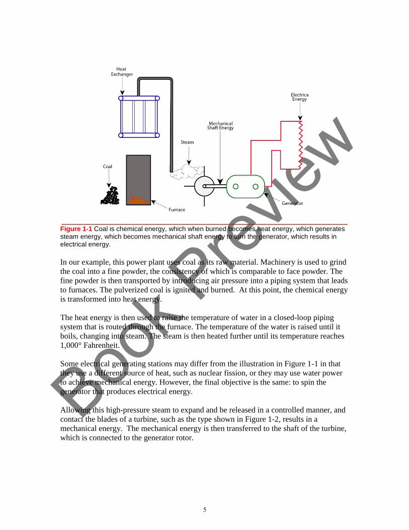
Book P
review
________________________________________________ Figure 1-1 Coal is chemical energy, which when burned becomes heat energy, which generates steam energy, which becomes mechanical shaft energy to turn the generator, which results in electrical energy.
In our example, this power plant uses coal as its raw material. Machinery is used to grind
the coal into a fine powder, the consistency of which is comparable to face powder. The
fine powder is then transported by introducing air pressure into a piping system that leads
to furnaces. The pulverized coal is ignited and burned. At this point, the chemical energy
is transformed into heat energy.
The heat energy is then used to raise the temperature of water in a closed-loop piping
system that is routed through the furnace. The temperature of the water is raised until it
boils, changing into steam. The steam is then heated further until its temperature reaches
1,000° Fahrenheit.
Some electrical generating stations may differ from the illustration in Figure 1-1 in that
they use a different source of heat, such as nuclear fission, or they may use water power
to achieve mechanical energy. However, the final objective is the same: to spin the
generator that produces electrical energy.
Allowing this high-pressure steam to expand and be released in a controlled manner, and
contact the blades of a turbine, such as the type shown in Figure 1-2, results in a
mechanical energy. The mechanical energy is then transferred to the shaft of the turbine,
which is connected to the generator rotor.
5
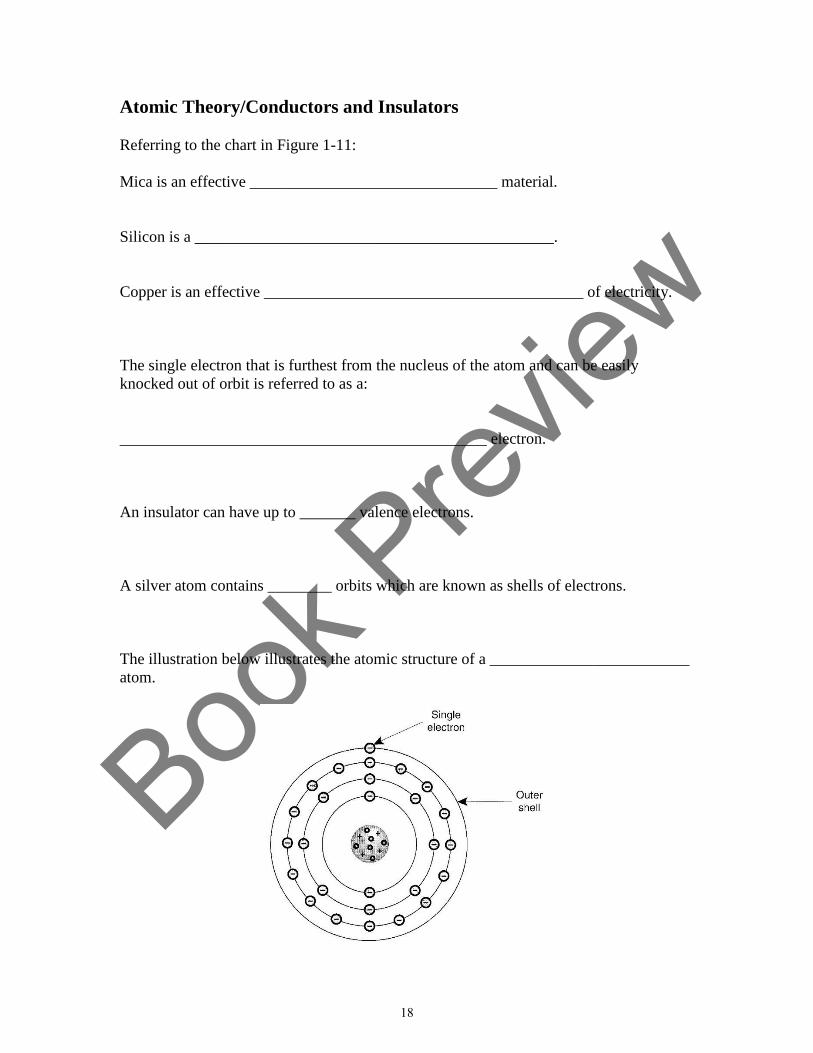
Book P
review
Atomic Theory/Conductors and Insulators
Referring to the chart in Figure 1-11:
Mica is an effective _______________________________ material.
Silicon is a _____________________________________________.
Copper is an effective ________________________________________ of electricity.
The single electron that is furthest from the nucleus of the atom and can be easily
knocked out of orbit is referred to as a:
______________________________________________ electron.
An insulator can have up to _______ valence electrons.
A silver atom contains ________ orbits which are known as shells of electrons.
The illustration below illustrates the atomic structure of a _________________________
atom.
18
Book P
review
UNIT
2
Alternating Current, Direct Current And
Electrical Power
Learning Objectives:
After studying this unit, you will be able to:
1. Describe the difference between alternating current and direct current.
2. Understand the relationship between voltage, amperage and resistance in regard to Ohm’s
Law.
3. Explain how the electric company charges customers for electricity.
The power supplied to HVACR equipment is alternating current (AC). As described in Unit 1,
alternating current is generated through the process of cutting the lines of force of a magnetic
field with a conductor. From a practical standpoint, this means that alternating current reverses
its direction from negative to positive every time the conductor cuts the lines of force of both
poles of the magnet.
When considering direct current (DC) in HVACR equipment, it is used to power printed circuit
board control systems and related solid state components. This unit will discuss both AC and DC
current, Ohm’s Law, and electrical power.
21
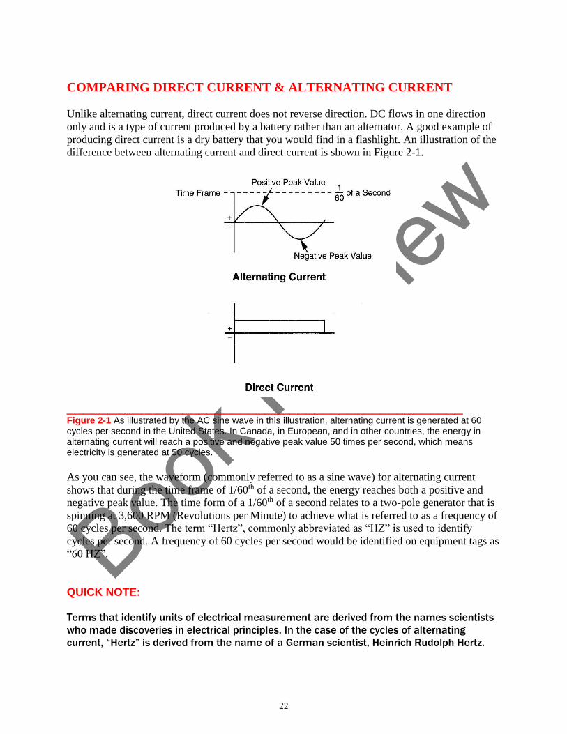
Book P
review
COMPARING DIRECT CURRENT & ALTERNATING CURRENT
Unlike alternating current, direct current does not reverse direction. DC flows in one direction
only and is a type of current produced by a battery rather than an alternator. A good example of
producing direct current is a dry battery that you would find in a flashlight. An illustration of the
difference between alternating current and direct current is shown in Figure 2-1.
________________________________________________ Figure 2-1 As illustrated by the AC sine wave in this illustration, alternating current is generated at 60 cycles per second in the United States. In Canada, in European, and in other countries, the energy in alternating current will reach a positive and negative peak value 50 times per second, which means electricity is generated at 50 cycles.
As you can see, the waveform (commonly referred to as a sine wave) for alternating current
shows that during the time frame of 1/60th of a second, the energy reaches both a positive and
negative peak value. The time form of a 1/60th of a second relates to a two-pole generator that is
spinning at 3,600 RPM (Revolutions per Minute) to achieve what is referred to as a frequency of
60 cycles per second. The term “Hertz”, commonly abbreviated as “HZ” is used to identify
cycles per second. A frequency of 60 cycles per second would be identified on equipment tags as
“60 HZ”.
QUICK NOTE:
Terms that identify units of electrical measurement are derived from the names scientists
who made discoveries in electrical principles. In the case of the cycles of alternating
current, “Hertz” is derived from the name of a German scientist, Heinrich Rudolph Hertz.
22
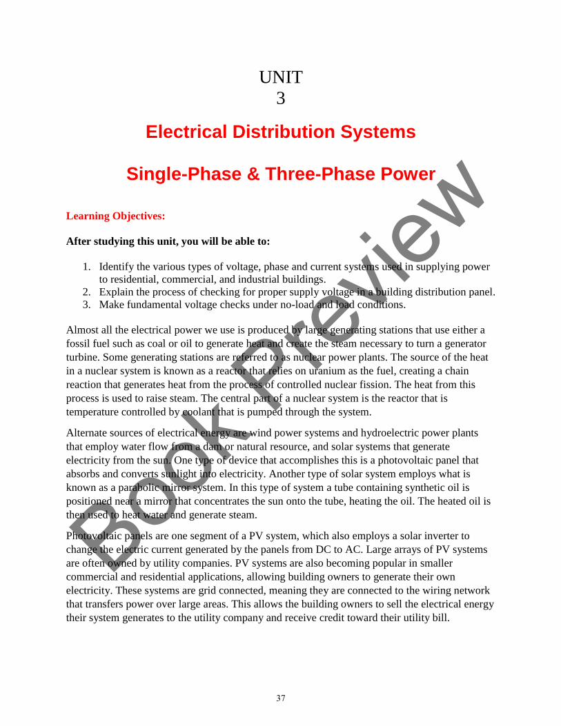
Book P
review
UNIT
3
Electrical Distribution Systems
Single-Phase & Three-Phase Power
Learning Objectives:
After studying this unit, you will be able to:
1. Identify the various types of voltage, phase and current systems used in supplying power
to residential, commercial, and industrial buildings.
2. Explain the process of checking for proper supply voltage in a building distribution panel.
3. Make fundamental voltage checks under no-load and load conditions.
Almost all the electrical power we use is produced by large generating stations that use either a
fossil fuel such as coal or oil to generate heat and create the steam necessary to turn a generator
turbine. Some generating stations are referred to as nuclear power plants. The source of the heat
in a nuclear system is known as a reactor that relies on uranium as the fuel, creating a chain
reaction that generates heat from the process of controlled nuclear fission. The heat from this
process is used to raise steam. The central part of a nuclear system is the reactor that is
temperature controlled by coolant that is pumped through the system.
Alternate sources of electrical energy are wind power systems and hydroelectric power plants
that employ water flow from a dam or natural resource, and solar systems that generate
electricity from the sun. One type of device that accomplishes this is a photovoltaic panel that
absorbs and converts sunlight into electricity. Another type of solar system employs what is
known as a parabolic mirror system. In this type of system a tube containing synthetic oil is
positioned near a mirror that concentrates the sun onto the tube, heating the oil. The heated oil is
then used to heat water and generate steam.
Photovoltaic panels are one segment of a PV system, which also employs a solar inverter to
change the electric current generated by the panels from DC to AC. Large arrays of PV systems
are often owned by utility companies. PV systems are also becoming popular in smaller
commercial and residential applications, allowing building owners to generate their own
electricity. These systems are grid connected, meaning they are connected to the wiring network
that transfers power over large areas. This allows the building owners to sell the electrical energy
their system generates to the utility company and receive credit toward their utility bill.
37
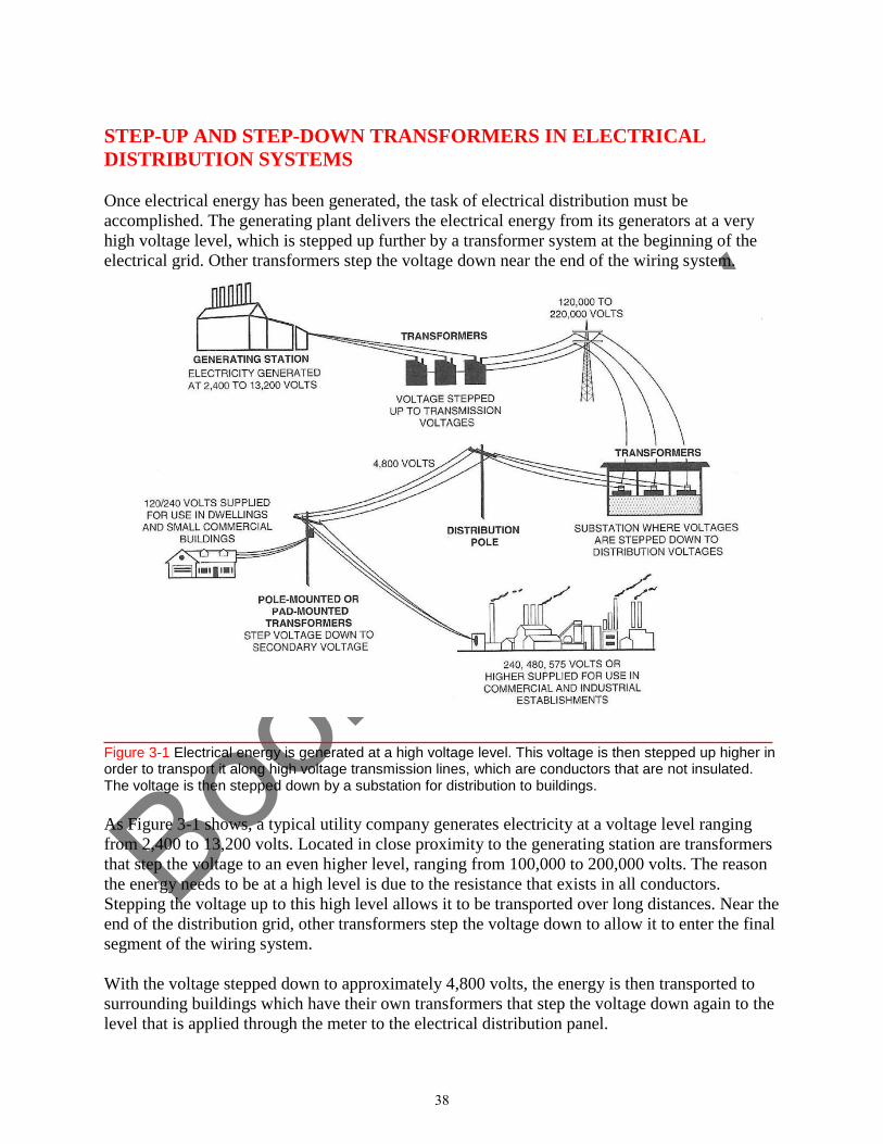
Book P
review
STEP-UP AND STEP-DOWN TRANSFORMERS IN ELECTRICAL
DISTRIBUTION SYSTEMS
Once electrical energy has been generated, the task of electrical distribution must be
accomplished. The generating plant delivers the electrical energy from its generators at a very
high voltage level, which is stepped up further by a transformer system at the beginning of the
electrical grid. Other transformers step the voltage down near the end of the wiring system.
____________________________________________________ Figure 3-1 Electrical energy is generated at a high voltage level. This voltage is then stepped up higher in order to transport it along high voltage transmission lines, which are conductors that are not insulated. The voltage is then stepped down by a substation for distribution to buildings.
As Figure 3-1 shows, a typical utility company generates electricity at a voltage level ranging
from 2,400 to 13,200 volts. Located in close proximity to the generating station are transformers
that step the voltage to an even higher level, ranging from 100,000 to 200,000 volts. The reason
the energy needs to be at a high level is due to the resistance that exists in all conductors.
Stepping the voltage up to this high level allows it to be transported over long distances. Near the
end of the distribution grid, other transformers step the voltage down to allow it to enter the final
segment of the wiring system.
With the voltage stepped down to approximately 4,800 volts, the energy is then transported to
surrounding buildings which have their own transformers that step the voltage down again to the
level that is applied through the meter to the electrical distribution panel.
38
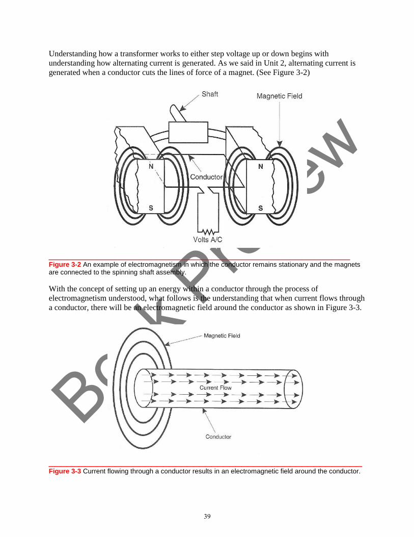
Book P
review
Understanding how a transformer works to either step voltage up or down begins with
understanding how alternating current is generated. As we said in Unit 2, alternating current is
generated when a conductor cuts the lines of force of a magnet. (See Figure 3-2)
__________________________________________________ Figure 3-2 An example of electromagnetism in which the conductor remains stationary and the magnets are connected to the spinning shaft assembly.
With the concept of setting up an energy within a conductor through the process of
electromagnetism understood, what follows is the understanding that when current flows through
a conductor, there will be an electromagnetic field around the conductor as shown in Figure 3-3.
____________________________________________________ Figure 3-3 Current flowing through a conductor results in an electromagnetic field around the conductor.
39
Book P
review
UNIT
4
Electrical Supply Circuit Protection
Fuses & Circuit Breakers
Learning Objectives:
After studying this unit, you will be able to:
1. Explain how a fuse acts as a protective device in an electrical circuit.
2. Identify the different types of fuses used in HVACR equipment circuits.
3. Explain the process of testing to determine if a fuse in a disconnect box has blown.
4. Describe the method of operation of an electrical system circuit breaker.
HVACR electrical systems, as with any electrical circuit, must be protected. Protection is
necessary to prevent excessive temperature situations that could damage the power source or
cause wiring and components to fail in the event of an overload condition. A severe overload
condition can create a fire hazard.
The most common method of circuit protection begins with circuit breakers located in the
building distribution panel, and in the case of HVACR equipment, often also employs fuses at
the point of the wiring service to the equipment. In older buildings, if the electrical distribution
panel has not been upgraded, it is possible that fuses, rather than circuit breakers, will still be in
use.
It is the technician’s responsibility to be absolutely certain that the fuses being used in the
protection of HVACR equipment are the proper type of fuse for the application, and that that
they are correctly rated for the specific circuit in which they are employed.
67
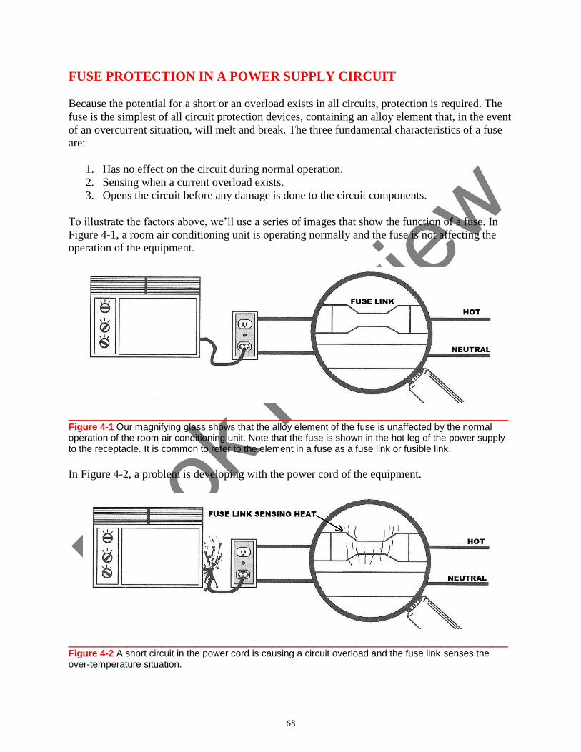
Book P
review
FUSE PROTECTION IN A POWER SUPPLY CIRCUIT
Because the potential for a short or an overload exists in all circuits, protection is required. The
fuse is the simplest of all circuit protection devices, containing an alloy element that, in the event
of an overcurrent situation, will melt and break. The three fundamental characteristics of a fuse
are:
1. Has no effect on the circuit during normal operation.
2. Sensing when a current overload exists.
3. Opens the circuit before any damage is done to the circuit components.
To illustrate the factors above, we’ll use a series of images that show the function of a fuse. In
Figure 4-1, a room air conditioning unit is operating normally and the fuse is not affecting the
operation of the equipment.
____________________________________________________ Figure 4-1 Our magnifying glass shows that the alloy element of the fuse is unaffected by the normal operation of the room air conditioning unit. Note that the fuse is shown in the hot leg of the power supply to the receptacle. It is common to refer to the element in a fuse as a fuse link or fusible link.
In Figure 4-2, a problem is developing with the power cord of the equipment.
____________________________________________________ Figure 4-2 A short circuit in the power cord is causing a circuit overload and the fuse link senses the over-temperature situation.
68
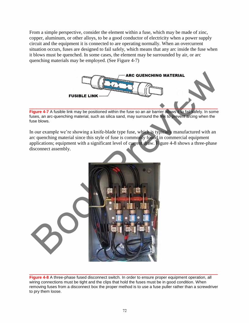
Book P
review
From a simple perspective, consider the element within a fuse, which may be made of zinc,
copper, aluminum, or other alloys, to be a good conductor of electricity when a power supply
circuit and the equipment it is connected to are operating normally. When an overcurrent
situation occurs, fuses are designed to fail safely, which means that any arc inside the fuse when
it blows must be quenched. In some cases, the element may be surrounded by air, or arc
quenching materials may be employed. (See Figure 4-7)
____________________________________________________ Figure 4-7 A fusible link may be positioned within the fuse so an air barrier allows it to fail safely. In some fuses, an arc-quenching material, such as silica sand, may surround the link to prevent arcing when the fuse blows.
In our example we’re showing a knife-blade type fuse, which is typically manufactured with an
arc quenching material since this style of fuse is commonly found in commercial equipment
applications; equipment with a significant level of current draw. Figure 4-8 shows a three-phase
disconnect assembly.
____________________________________________________ Figure 4-8 A three-phase fused disconnect switch. In order to ensure proper equipment operation, all wiring connections must be tight and the clips that hold the fuses must be in good condition. When removing fuses from a disconnect box the proper method is to use a fuse puller rather than a screwdriver to pry them loose.
72
Book P
review
UNIT FOUR SUMMARY _____________________________________________________________________________
HVACR electrical systems, as with any electrical circuit, must be protected to prevent a severe
overload condition that can create a fire hazard.
In the case of HVACR equipment, the breaker in the distribution panel and a fused disconnect
box are typically used to protect the electrical circuit. In older buildings, if the electrical
distribution panel has not be upgraded, it is possible that fuses, rather than circuit breakers, will
still be in use.
It is the technician’s responsibility to be absolutely certain that proper fuses are being used in the
protection of HVACR equipment.
The three fundamental characteristics of a fuse are:
1. Has no effect on the circuit during normal operation.
2. Sensing when a current overload exists.
3. Opens the circuit before any damage is done to the circuit components.
In addition to understanding the method of operation of a fuse, technicians need to be aware that
different styles of fuses are employed depending on the specific type of circuit and equipment
the fuse is protecting.
Time delay fuses, also known as dual element fuses, must be able to withstand an excessive level
of current draw for a short period of time.
Not all equipment is protected by both a circuit breaker and a fused disconnect. In some cases, a
disconnect switch may not be fused, and the only protection in the equipment circuit is a circuit
breaker inside the building.
When an overcurrent situation occurs, fuses are designed to fail safely, which means that any arc
inside the fuse when it blows must be quenched. In some cases, the element may be surrounded
by air, or arc quenching materials may be employed.
Working from the perspective that troubleshooting is the systematic elimination of the
possibilities, it makes sense to begin the process within the disconnect box because it is
fundamentally in the “middle” of the electrical circuit. It also allows for an illustration of the
“If/Then” approach to troubleshooting
When checking for power in this particular style of fused disconnect, removing the safety shield
will show the Line wiring connections from the breaker in the distribution panel that brings
power into the disconnect assembly and the Load wiring connections that take the power out of
the box to the equipment.
Always use extreme caution when removing safety shields to expose wiring connections!
When the circuit breaker in the main distribution panel is turned on, wiring inside the
disconnect box will be hot!
87
Book P
review
UNIT
5
Proper Use of Test Instruments
Learning Objectives:
After studying this unit, you will be able to:
1. Explain the safety aspects regarding the proper use of analog and digital meters.
2. Describe how to accomplish continuity, resistance, voltage, current, capacitance, and
temperature measurements with multi-meters.
3. Explain the process of checking circuits and electrical components relative to
troubleshooting and repairing HVACR equipment.
HVACR service managers face a variety of challenges in the day-to-day operation of their
department. And surveys show that one of the issues they deal with on a regular basis in their in-
house training sessions is ensuring that technicians are able to understand and properly use test
instruments.
Using test devices involves more than safely checking hot circuits with a voltmeter to ensure that
power is applied to equipment as we discussed in Unit Four. Technicians must also understand
the subtle difference between testing for continuity and resistance of components, and properly
interpreting that information. And they must also know how to apply the information a meter
shows in regard to current draw of a given component and/or the overall operation of the
equipment, and the importance of temperature measurements where necessary in order to
evaluate the operation of an electrical system.
This unit will discuss the fundamental principles of the operation of analog meters because, as
with any technical skill, complete mastery of a craft requires a firm foundation of understanding
all aspects of a subject.
An overview of how to use digital test equipment to obtain good information about a given
component or an electrical system being tested, and how to relate that information to
troubleshooting and repairing equipment, is also discussed in this unit.
93
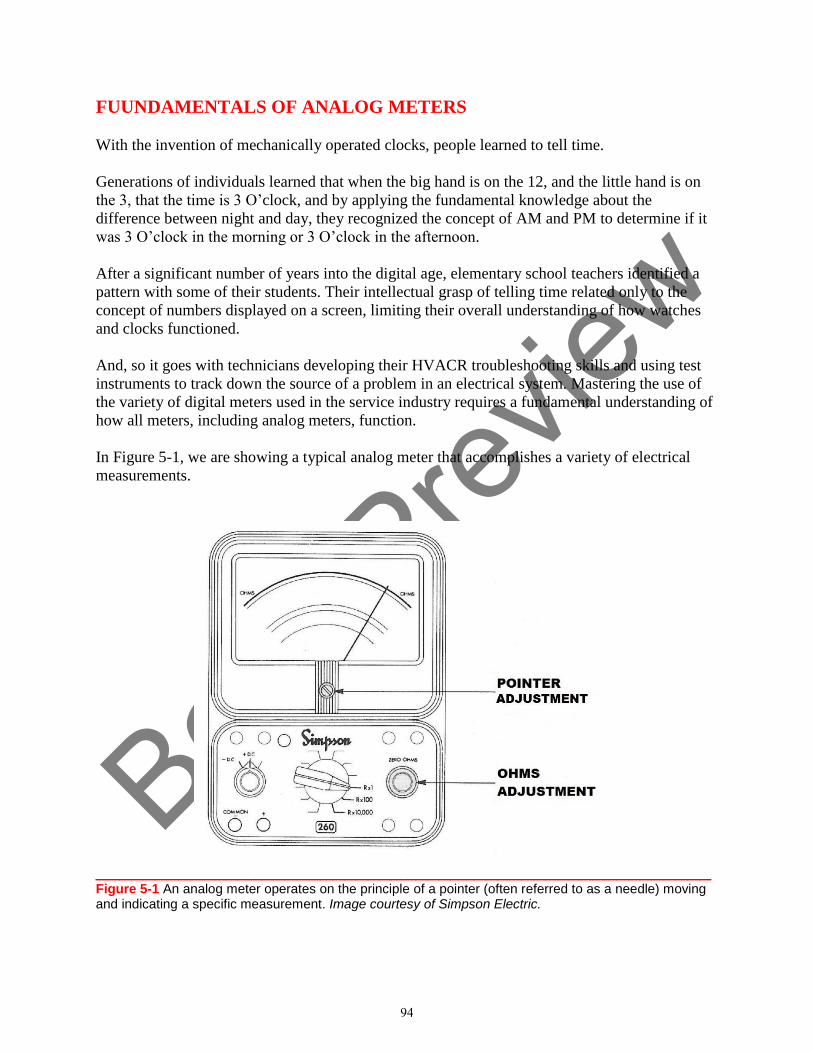
Book P
review
FUUNDAMENTALS OF ANALOG METERS
With the invention of mechanically operated clocks, people learned to tell time.
Generations of individuals learned that when the big hand is on the 12, and the little hand is on
the 3, that the time is 3 O’clock, and by applying the fundamental knowledge about the
difference between night and day, they recognized the concept of AM and PM to determine if it
was 3 O’clock in the morning or 3 O’clock in the afternoon.
After a significant number of years into the digital age, elementary school teachers identified a
pattern with some of their students. Their intellectual grasp of telling time related only to the
concept of numbers displayed on a screen, limiting their overall understanding of how watches
and clocks functioned.
And, so it goes with technicians developing their HVACR troubleshooting skills and using test
instruments to track down the source of a problem in an electrical system. Mastering the use of
the variety of digital meters used in the service industry requires a fundamental understanding of
how all meters, including analog meters, function.
In Figure 5-1, we are showing a typical analog meter that accomplishes a variety of electrical
measurements.
____________________________________________________ Figure 5-1 An analog meter operates on the principle of a pointer (often referred to as a needle) moving and indicating a specific measurement. Image courtesy of Simpson Electric.
94
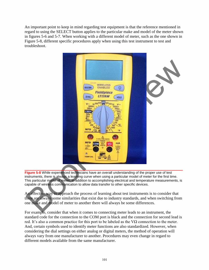
Book P
review
An important point to keep in mind regarding test equipment is that the reference mentioned in
regard to using the SELECT button applies to the particular make and model of the meter shown
in figures 5-6 and 5-7. When working with a different model of meter, such as the one shown in
Figure 5-8, different specific procedures apply when using this test instrument to test and
troubleshoot.
____________________________________________________ Figure 5-8 While experienced technicians have an overall understanding of the proper use of test instruments, there is always a learning curve when using a particular model of meter for the first time. This particular model of meter, in addition to accomplishing electrical and temperature measurements, is capable of wireless communication to allow data transfer to other specific devices.
An effective way to approach the process of learning about test instruments is to consider that
there are always some similarities that exist due to industry standards, and when switching from
one make and model of meter to another there will always be some differences.
For example, consider that when it comes to connecting meter leads to an instrument, the
standard code for the connection to the COM port is black and the connection for second lead is
red. It’s also a common practice for this port to be labeled as the VΩ connection to the meter.
And, certain symbols used to identify meter functions are also standardized. However, when
considering the dial settings on either analog or digital meters, the method of operation will
always vary from one manufacturer to another. Procedures may even change in regard to
different models available from the same manufacturer.
101
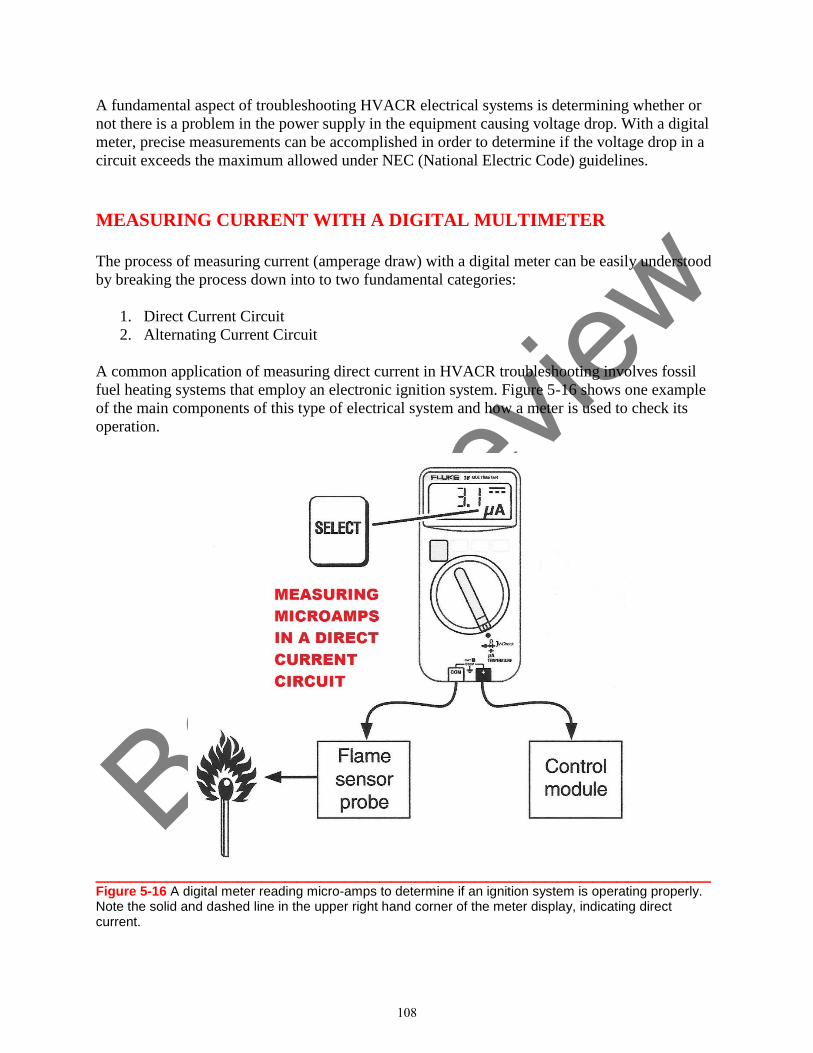
Book P
review
A fundamental aspect of troubleshooting HVACR electrical systems is determining whether or
not there is a problem in the power supply in the equipment causing voltage drop. With a digital
meter, precise measurements can be accomplished in order to determine if the voltage drop in a
circuit exceeds the maximum allowed under NEC (National Electric Code) guidelines.
MEASURING CURRENT WITH A DIGITAL MULTIMETER
The process of measuring current (amperage draw) with a digital meter can be easily understood
by breaking the process down into to two fundamental categories:
1. Direct Current Circuit
2. Alternating Current Circuit
A common application of measuring direct current in HVACR troubleshooting involves fossil
fuel heating systems that employ an electronic ignition system. Figure 5-16 shows one example
of the main components of this type of electrical system and how a meter is used to check its
operation.
____________________________________________________ Figure 5-16 A digital meter reading micro-amps to determine if an ignition system is operating properly. Note the solid and dashed line in the upper right hand corner of the meter display, indicating direct current.
108
Book P
review
HVACR TROUBLESHOOTING FUNDAMENTALS
Electricity & Wiring Diagrams
SECTION
2
WIRING DIAGRAMS AND HVACR SYSTEM COMPONENTS
In order to effectively troubleshoot HVACR equipment, you must be familiar with the
basic principles of electricity. And, once you have a firm understanding of these
fundamental concepts, you can apply that knowledge to test and evaluate the electro-
mechanical and electronic components used in HVACR systems, and the wiring that
connects them together, to pinpoint the source of a problem.
127
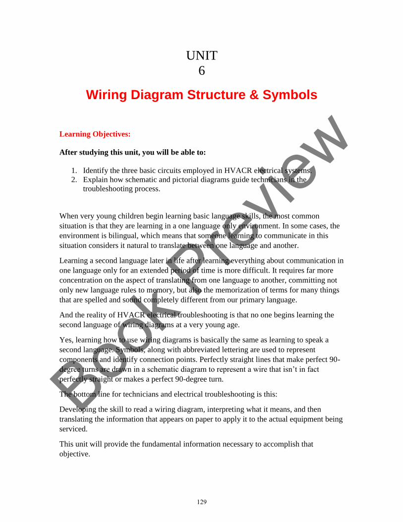
Book P
review
UNIT
6
Wiring Diagram Structure & Symbols
Learning Objectives:
After studying this unit, you will be able to:
1. Identify the three basic circuits employed in HVACR electrical systems.
2. Explain how schematic and pictorial diagrams guide technicians in the
troubleshooting process.
When very young children begin learning basic language skills, the most common
situation is that they are learning in a one language only environment. In some cases, the
environment is bilingual, which means that someone learning to communicate in this
situation considers it natural to translate between one language and another.
Learning a second language later in life after learning everything about communication in
one language only for an extended period of time is more difficult. It requires far more
concentration on the aspect of translating from one language to another, committing not
only new language rules to memory, but also the memorization of terms for many things
that are spelled and sound completely different from our primary language.
And the reality of HVACR electrical troubleshooting is that no one begins learning the
second language of wiring diagrams at a very young age.
Yes, learning how to use wiring diagrams is basically the same as learning to speak a
second language. Symbols, along with abbreviated lettering are used to represent
components and identify connection points. Perfectly straight lines that make perfect 90-
degree turns are drawn in a schematic diagram to represent a wire that isn’t in fact
perfectly straight or makes a perfect 90-degree turn.
The bottom line for technicians and electrical troubleshooting is this:
Developing the skill to read a wiring diagram, interpreting what it means, and then
translating the information that appears on paper to apply it to the actual equipment being
serviced.
This unit will provide the fundamental information necessary to accomplish that
objective.
129
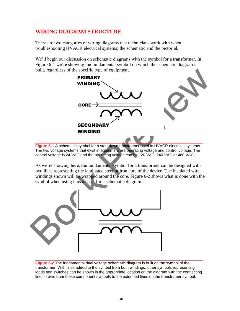
Book P
review
WIRING DIAGRAM STRUCTURE
There are two categories of wiring diagrams that technicians work with when
troubleshooting HVACR electrical systems; the schematic and the pictorial.
We’ll begin our discussion on schematic diagrams with the symbol for a transformer. In
Figure 6-1 we’re showing the fundamental symbol on which the schematic diagram is
built, regardless of the specific type of equipment.
________________________________________________ Figure 6-1 A schematic symbol for a step-down transformer used in HVACR electrical systems. The two voltage systems that exist in equipment are operating voltage and control voltage. The control voltage is 24 VAC and the operating voltage can be 120 VAC, 240 VAC or 480 VAC.
As we’re showing here, the fundamental symbol for a transformer can be designed with
two lines representing the laminated steel or iron core of the device. The insulated wire
windings shown will be wrapped around the core. Figure 6-2 shows what is done with the
symbol when using it as a basis for a schematic diagram.
________________________________________________ Figure 6-2 The fundamental dual voltage schematic diagram is built on the symbol of the transformer. With lines added to the symbol from both windings, other symbols representing loads and switches can be shown in the appropriate location on the diagram with the connecting lines drawn from these component symbols to the extended lines on the transformer symbol.
130
Book P
review
In Figure 6-8, with the test instrument set to a low resistance scale, an accurate reading of
the secondary winding resistance will be rendered. In this example, as we would expect,
the resistance of the secondary winding (3.3 Ohms) is lower than the reading obtained
when checking the primary winding because the secondary winding has fewer turns of
wire wrapped around the transformer core.
In Figure 6-9 the display screen is showing the reading your test instrument would
provide in the event that the secondary winding of the transformer has failed.
________________________________________________ Figure 6-9 The secondary winding of this transformer has failed. The meter display is showing “OL” which is an indicator of “Open Line”.
138
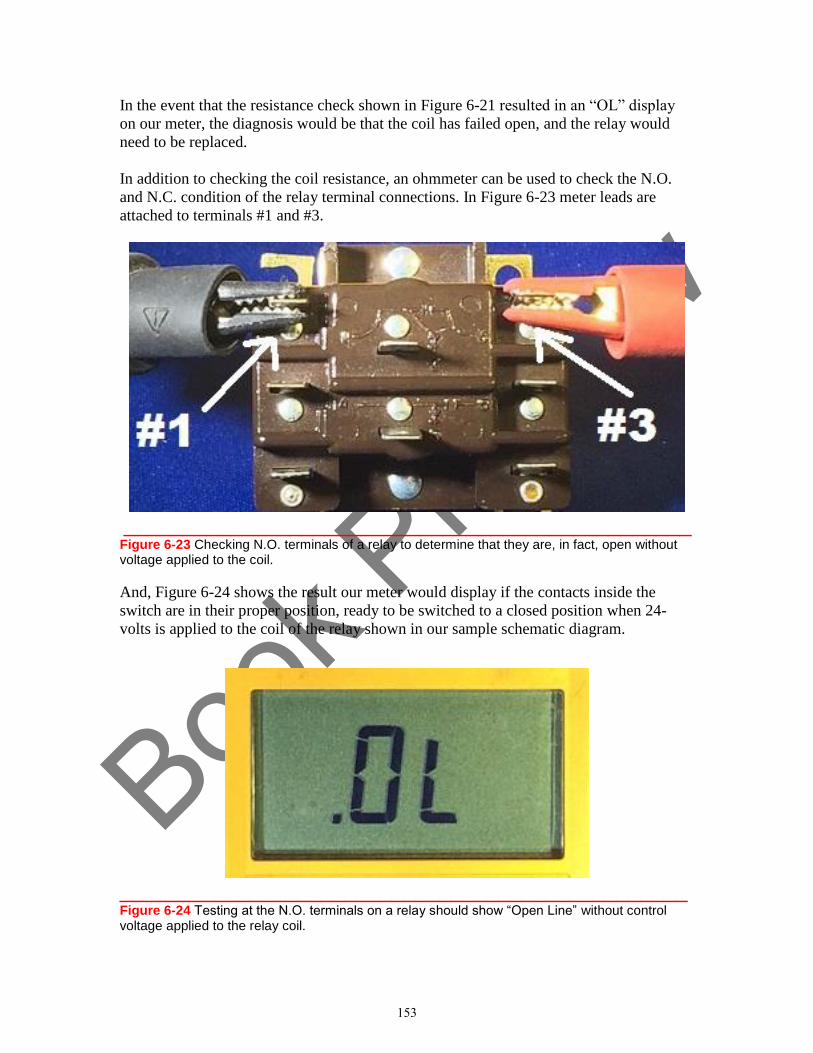
Book P
review
In the event that the resistance check shown in Figure 6-21 resulted in an “OL” display
on our meter, the diagnosis would be that the coil has failed open, and the relay would
need to be replaced.
In addition to checking the coil resistance, an ohmmeter can be used to check the N.O.
and N.C. condition of the relay terminal connections. In Figure 6-23 meter leads are
attached to terminals #1 and #3.
________________________________________________ Figure 6-23 Checking N.O. terminals of a relay to determine that they are, in fact, open without voltage applied to the coil.
And, Figure 6-24 shows the result our meter would display if the contacts inside the
switch are in their proper position, ready to be switched to a closed position when 24-
volts is applied to the coil of the relay shown in our sample schematic diagram.
________________________________________________ Figure 6-24 Testing at the N.O. terminals on a relay should show “Open Line” without control voltage applied to the relay coil.
153
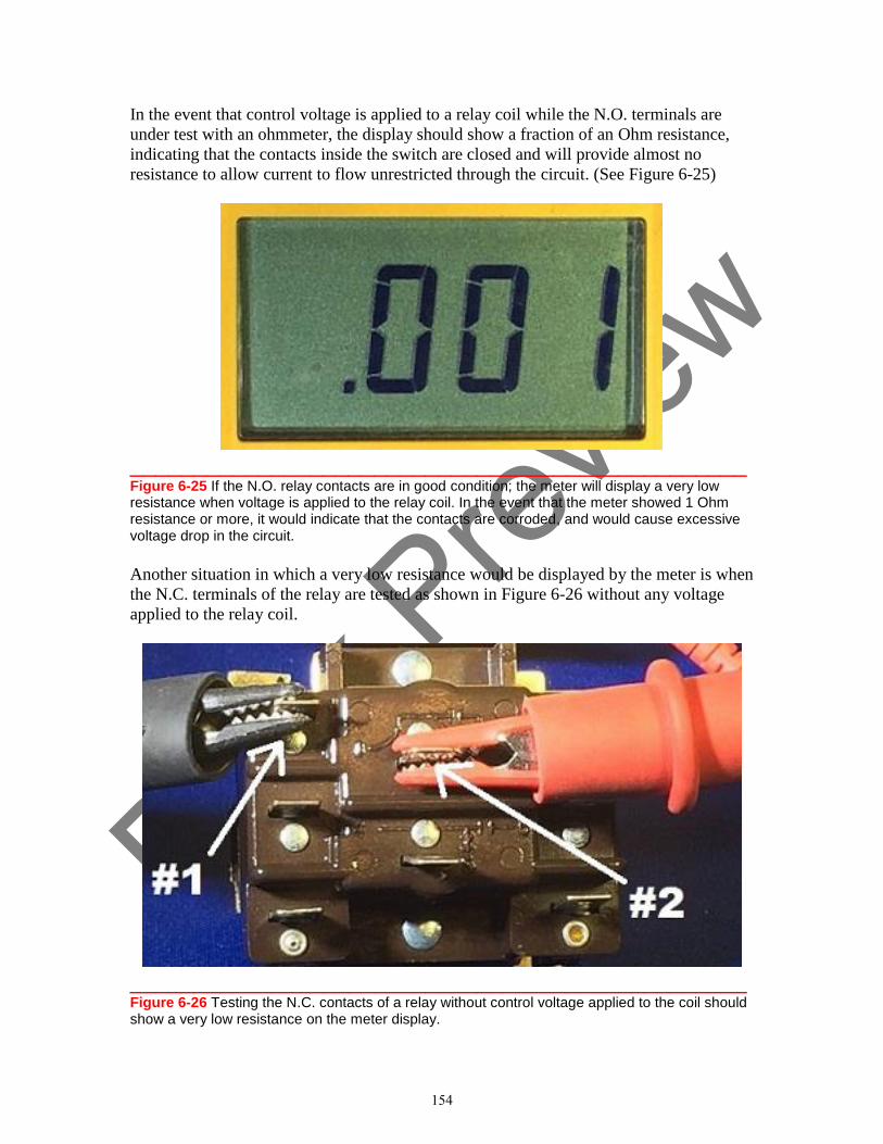
Book P
review
In the event that control voltage is applied to a relay coil while the N.O. terminals are
under test with an ohmmeter, the display should show a fraction of an Ohm resistance,
indicating that the contacts inside the switch are closed and will provide almost no
resistance to allow current to flow unrestricted through the circuit. (See Figure 6-25)
________________________________________________ Figure 6-25 If the N.O. relay contacts are in good condition; the meter will display a very low resistance when voltage is applied to the relay coil. In the event that the meter showed 1 Ohm resistance or more, it would indicate that the contacts are corroded, and would cause excessive voltage drop in the circuit.
Another situation in which a very low resistance would be displayed by the meter is when
the N.C. terminals of the relay are tested as shown in Figure 6-26 without any voltage
applied to the relay coil.
________________________________________________ Figure 6-26 Testing the N.C. contacts of a relay without control voltage applied to the coil should show a very low resistance on the meter display.
154
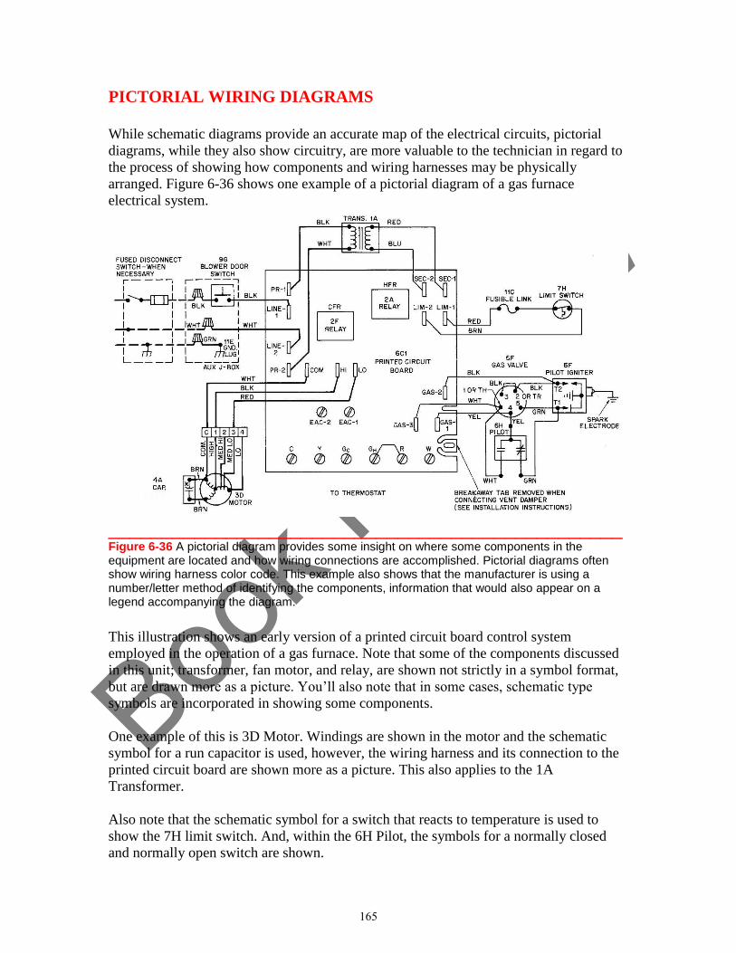
Book P
review
PICTORIAL WIRING DIAGRAMS
While schematic diagrams provide an accurate map of the electrical circuits, pictorial
diagrams, while they also show circuitry, are more valuable to the technician in regard to
the process of showing how components and wiring harnesses may be physically
arranged. Figure 6-36 shows one example of a pictorial diagram of a gas furnace
electrical system.
________________________________________________ Figure 6-36 A pictorial diagram provides some insight on where some components in the equipment are located and how wiring connections are accomplished. Pictorial diagrams often show wiring harness color code. This example also shows that the manufacturer is using a number/letter method of identifying the components, information that would also appear on a legend accompanying the diagram. This illustration shows an early version of a printed circuit board control system
employed in the operation of a gas furnace. Note that some of the components discussed
in this unit; transformer, fan motor, and relay, are shown not strictly in a symbol format,
but are drawn more as a picture. You’ll also note that in some cases, schematic type
symbols are incorporated in showing some components.
One example of this is 3D Motor. Windings are shown in the motor and the schematic
symbol for a run capacitor is used, however, the wiring harness and its connection to the
printed circuit board are shown more as a picture. This also applies to the 1A
Transformer.
Also note that the schematic symbol for a switch that reacts to temperature is used to
show the 7H limit switch. And, within the 6H Pilot, the symbols for a normally closed
and normally open switch are shown.
165
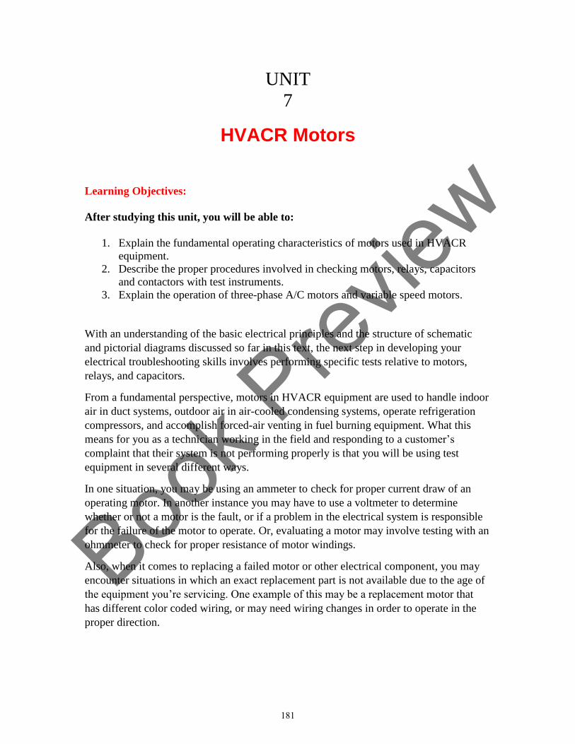
Book P
review
UNIT
7
HVACR Motors
Learning Objectives:
After studying this unit, you will be able to:
1. Explain the fundamental operating characteristics of motors used in HVACR
equipment.
2. Describe the proper procedures involved in checking motors, relays, capacitors
and contactors with test instruments.
3. Explain the operation of three-phase A/C motors and variable speed motors.
With an understanding of the basic electrical principles and the structure of schematic
and pictorial diagrams discussed so far in this text, the next step in developing your
electrical troubleshooting skills involves performing specific tests relative to motors,
relays, and capacitors.
From a fundamental perspective, motors in HVACR equipment are used to handle indoor
air in duct systems, outdoor air in air-cooled condensing systems, operate refrigeration
compressors, and accomplish forced-air venting in fuel burning equipment. What this
means for you as a technician working in the field and responding to a customer’s
complaint that their system is not performing properly is that you will be using test
equipment in several different ways.
In one situation, you may be using an ammeter to check for proper current draw of an
operating motor. In another instance you may have to use a voltmeter to determine
whether or not a motor is the fault, or if a problem in the electrical system is responsible
for the failure of the motor to operate. Or, evaluating a motor may involve testing with an
ohmmeter to check for proper resistance of motor windings.
Also, when it comes to replacing a failed motor or other electrical component, you may
encounter situations in which an exact replacement part is not available due to the age of
the equipment you’re servicing. One example of this may be a replacement motor that
has different color coded wiring, or may need wiring changes in order to operate in the
proper direction.
181
Book P
review
Another aspect of this is that it’s very likely you will encounter situations in which a
previous repair was performed and a component that was not classified as OEM (Original
Equipment Manufacturer) was used.
With a firm understanding of motors and how run and start capacitors, and relays and
contactors are used to control their operation, you will be able to avoid mistakes and also
correct unsafe and improper repairs that you encounter in the field.
This unit will discuss the fundamentals of motor design, and how capacitors are used to
help them start and run efficiently. It will also provide an overview of variable speed
motors.
182
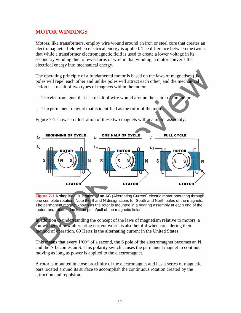
Book P
review
MOTOR WINDINGS
Motors, like transformers, employ wire wound around an iron or steel core that creates an
electromagnetic field when electrical energy is applied. The difference between the two is
that while a transformer electromagnetic field is used to create a lower voltage in its
secondary winding due to fewer turns of wire in that winding, a motor converts the
electrical energy into mechanical energy.
The operating principle of a fundamental motor is based on the laws of magnetism (like
poles will repel each other and unlike poles will attract each other) and the mechanical
action is a result of two types of magnets within the motor.
….The electromagnet that is a result of wire wound around the stator of the motor.
….The permanent magnet that is identified as the rotor of the motor.
Figure 7-1 shows an illustration of these two magnets within a motor assembly.
________________________________________________ Figure 7-1 A simplified illustration of an AC (Alternating Current) electric motor operating through one complete rotation. Note the S and N designations for South and North poles of the magnets. The permanent magnet known as the rotor is mounted in a bearing assembly at each end of the motor, and rotates due to the push/pull of the magnetic fields.
In addition to understanding the concept of the laws of magnetism relative to motors, a
knowledge of how alternating current works is also helpful when considering their
method of operation. 60 Hertz is the alternating current in the United States.
This means that every 1/60th of a second, the S pole of the electromagnet becomes an N,
and the N becomes an S. This polarity switch causes the permanent magnet to continue
moving as long as power is applied to the electromagnet.
A rotor is mounted in close proximity of the electromagnet and has a series of magnetic
bars located around its surface to accomplish the continuous rotation created by the
attraction and repulsion.
183
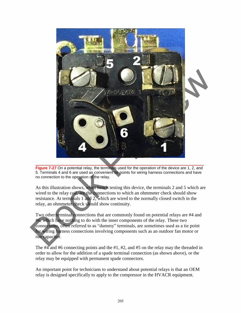
Book P
review
________________________________________________ Figure 7-27 On a potential relay, the terminals used for the operation of the device are 1, 2, and 5. Terminals 4 and 6 are used as convenient tie points for wiring harness connections and have no connection to the operation of the relay.
As this illustration shows, when bench testing this device, the terminals 2 and 5 which are
wired to the relay coil, are the connections to which an ohmmeter check should show
resistance. At terminals 1 and 2, which are wired to the normally closed switch in the
relay, an ohmmeter check should show continuity.
Two other terminal connections that are commonly found on potential relays are #4 and
#6, which have nothing to do with the inner components of the relay. These two
connections, often referred to as “dummy” terminals, are sometimes used as a tie point
for wiring harness connections involving components such as an outdoor fan motor or
run capacitor.
The #4 and #6 connecting points and the #1, #2, and #5 on the relay may the threaded in
order to allow for the addition of a spade terminal connection (as shown above), or the
relay may be equipped with permanent spade connectors.
An important point for technicians to understand about potential relays is that an OEM
relay is designed specifically to apply to the compressor in the HVACR equipment.
205
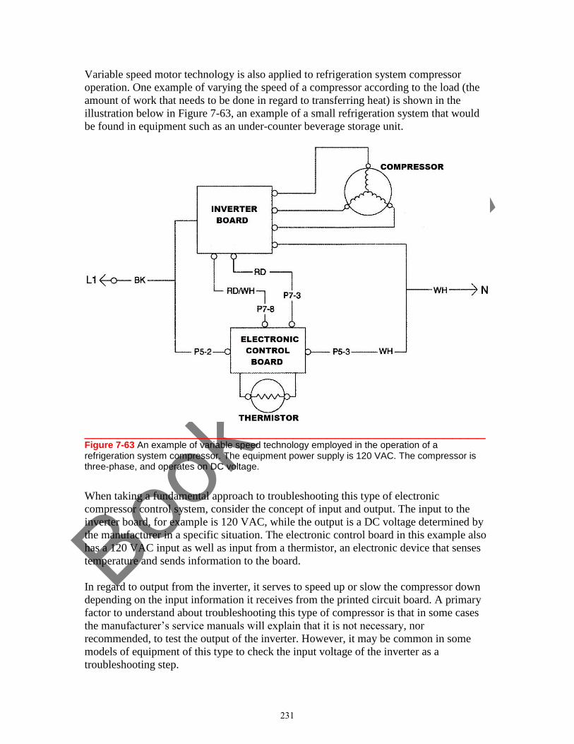
Book P
review
Variable speed motor technology is also applied to refrigeration system compressor
operation. One example of varying the speed of a compressor according to the load (the
amount of work that needs to be done in regard to transferring heat) is shown in the
illustration below in Figure 7-63, an example of a small refrigeration system that would
be found in equipment such as an under-counter beverage storage unit.
________________________________________________ Figure 7-63 An example of variable speed technology employed in the operation of a refrigeration system compressor. The equipment power supply is 120 VAC. The compressor is three-phase, and operates on DC voltage.
When taking a fundamental approach to troubleshooting this type of electronic
compressor control system, consider the concept of input and output. The input to the
inverter board, for example is 120 VAC, while the output is a DC voltage determined by
the manufacturer in a specific situation. The electronic control board in this example also
has a 120 VAC input as well as input from a thermistor, an electronic device that senses
temperature and sends information to the board.
In regard to output from the inverter, it serves to speed up or slow the compressor down
depending on the input information it receives from the printed circuit board. A primary
factor to understand about troubleshooting this type of compressor is that in some cases
the manufacturer’s service manuals will explain that it is not necessary, nor
recommended, to test the output of the inverter. However, it may be common in some
models of equipment of this type to check the input voltage of the inverter as a
troubleshooting step.
231
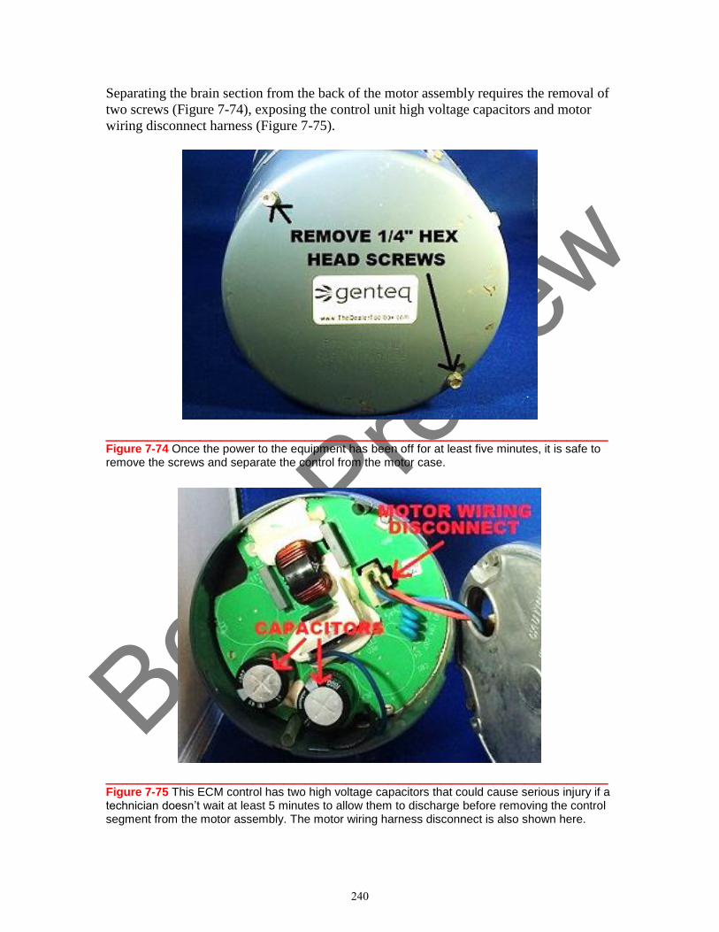
Book P
review
Separating the brain section from the back of the motor assembly requires the removal of
two screws (Figure 7-74), exposing the control unit high voltage capacitors and motor
wiring disconnect harness (Figure 7-75).
________________________________________________ Figure 7-74 Once the power to the equipment has been off for at least five minutes, it is safe to remove the screws and separate the control from the motor case.
________________________________________________ Figure 7-75 This ECM control has two high voltage capacitors that could cause serious injury if a technician doesn’t wait at least 5 minutes to allow them to discharge before removing the control segment from the motor assembly. The motor wiring harness disconnect is also shown here.
240
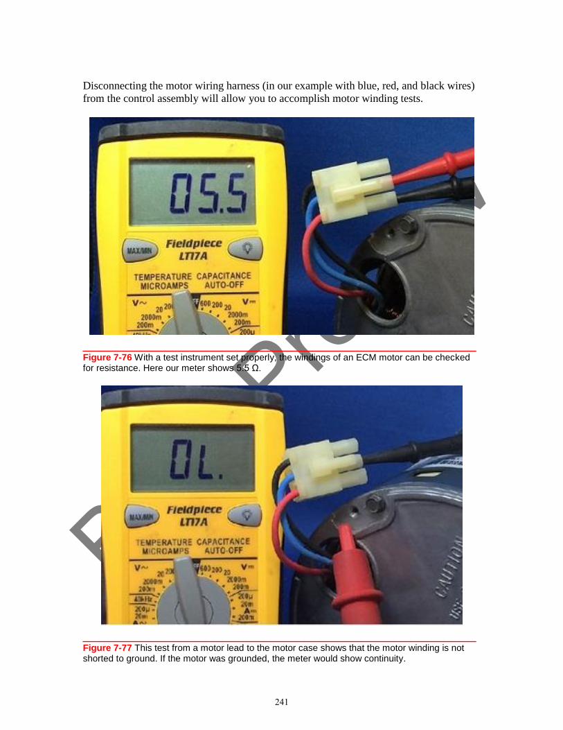
Book P
review
Disconnecting the motor wiring harness (in our example with blue, red, and black wires)
from the control assembly will allow you to accomplish motor winding tests.
________________________________________________ Figure 7-76 With a test instrument set properly, the windings of an ECM motor can be checked for resistance. Here our meter shows 5.5 Ω.
________________________________________________ Figure 7-77 This test from a motor lead to the motor case shows that the motor winding is not shorted to ground. If the motor was grounded, the meter would show continuity.
241
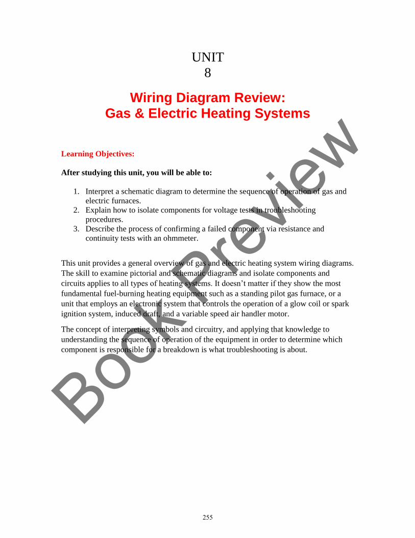
Book P
review
UNIT
8
Wiring Diagram Review: Gas & Electric Heating Systems
Learning Objectives:
After studying this unit, you will be able to:
1. Interpret a schematic diagram to determine the sequence of operation of gas and
electric furnaces.
2. Explain how to isolate components for voltage tests in troubleshooting
procedures.
3. Describe the process of confirming a failed component via resistance and
continuity tests with an ohmmeter.
This unit provides a general overview of gas and electric heating system wiring diagrams.
The skill to examine pictorial and schematic diagrams and isolate components and
circuits applies to all types of heating systems. It doesn’t matter if they show the most
fundamental fuel-burning heating equipment such as a standing pilot gas furnace, or a
unit that employs an electronic system that controls the operation of a glow coil or spark
ignition system, induced draft, and a variable speed air handler motor.
The concept of interpreting symbols and circuitry, and applying that knowledge to
understanding the sequence of operation of the equipment in order to determine which
component is responsible for a breakdown is what troubleshooting is about.
255
Book P
review
DEVICES & SEQUENCE OF EQUIPMENT OPERATION
The bottom line for HVACR technicians is that the majority of the time we are only
called upon when something stops working. On some occasions we may have the
opportunity to perform preventive maintenance checks on a system, and when this
occurs, we should consider it a golden opportunity to observe equipment and the
sequence of operation when the electrical system is working properly.
As an example, consider an on/off cycle for a gas furnace that employs a hot surface
ignition system and induced draft in the furnace vent….
….The thermostat calls for heat.
….The induced draft motor is energized.
….The hot surface ignitor is energized.
….The gas valve is energized, allowing gas flow to the burners.
….The blower motor is energized.
….The thermostat is satisfied when the room temperature rises to the set point.
….The gas valve is de-energized, stopping the flow of gas to the burners.
….The blower motor is de-energized on a time delay system.
And there we have it, an outline of the steps that a gas furnace goes through when it is
cycled on and off. Our simplified description of sequence begins with one switch (the
thermostat), explains the operation of the loads that do their job while the system is
providing heat, and describes what happens when the thermostat de-energizes the heat
source to end a cycle.
Other factors to understand about the sequence of operation of a gas furnace are:
….Additional switches in the furnace that make and break circuits to loads, some of
which are control or safety devices that react to temperature, and others that are within
relays that may be electromechanical or solid state design.
….The equipment can operate as intended because it employs a dual voltage system of a
120-Volt equipment power supply and a 24-Volt control voltage.
In regard to an electric furnace, the simplified sequence of operation can be described:
….The thermostat calls for heat.
….The blower motor is energized to ensure air flow across heating elements.
….The 24-volt control segment of a device is energized to allow an equipment voltage
switch within the device to close and energize a heating element.
….If necessary, additional control devices are employed to operate additional elements.
….The thermostat is satisfied, de-energizing the heating element(s).
….The blower motor is de-energized on a time delay system.
An electric furnace also requires additional switches for safety and component control.
256
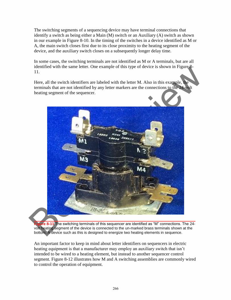
Book P
review
The switching segments of a sequencing device may have terminal connections that
identify a switch as being either a Main (M) switch or an Auxiliary (A) switch as shown
in our example in Figure 8-10. In the timing of the switches in a device identified as M or
A, the main switch closes first due to its close proximity to the heating segment of the
device, and the auxiliary switch closes on a subsequently longer delay time.
In some cases, the switching terminals are not identified as M or A terminals, but are all
identified with the same letter. One example of this type of device is shown in Figure 8-
11.
Here, all the switch identifiers are labeled with the letter M. Also in this example, the
terminals that are not identified by any letter markers are the connections to the 24-volt
heating segment of the sequencer.
________________________________________________ Figure 8-11 The switching terminals of this sequencer are identified as “M” connections. The 24-volt heating segment of the device is connected to the un-marked brass terminals shown at the bottom. A device such as this is designed to energize two heating elements in sequence.
An important factor to keep in mind about letter identifiers on sequencers in electric
heating equipment is that a manufacturer may employ an auxiliary switch that isn’t
intended to be wired to a heating element, but instead to another sequencer control
segment. Figure 8-12 illustrates how M and A switching assemblies are commonly wired
to control the operation of equipment.
266
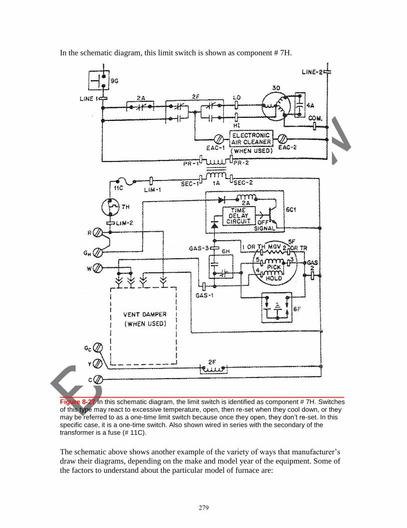
Book P
review
In the schematic diagram, this limit switch is shown as component # 7H.
________________________________________________ Figure 8-27 In this schematic diagram, the limit switch is identified as component # 7H. Switches of this type may react to excessive temperature, open, then re-set when they cool down, or they may be referred to as a one-time limit switch because once they open, they don’t re-set. In this specific case, it is a one-time switch. Also shown wired in series with the secondary of the transformer is a fuse (# 11C).
The schematic above shows another example of the variety of ways that manufacturer’s
draw their diagrams, depending on the make and model year of the equipment. Some of
the factors to understand about the particular model of furnace are:
279
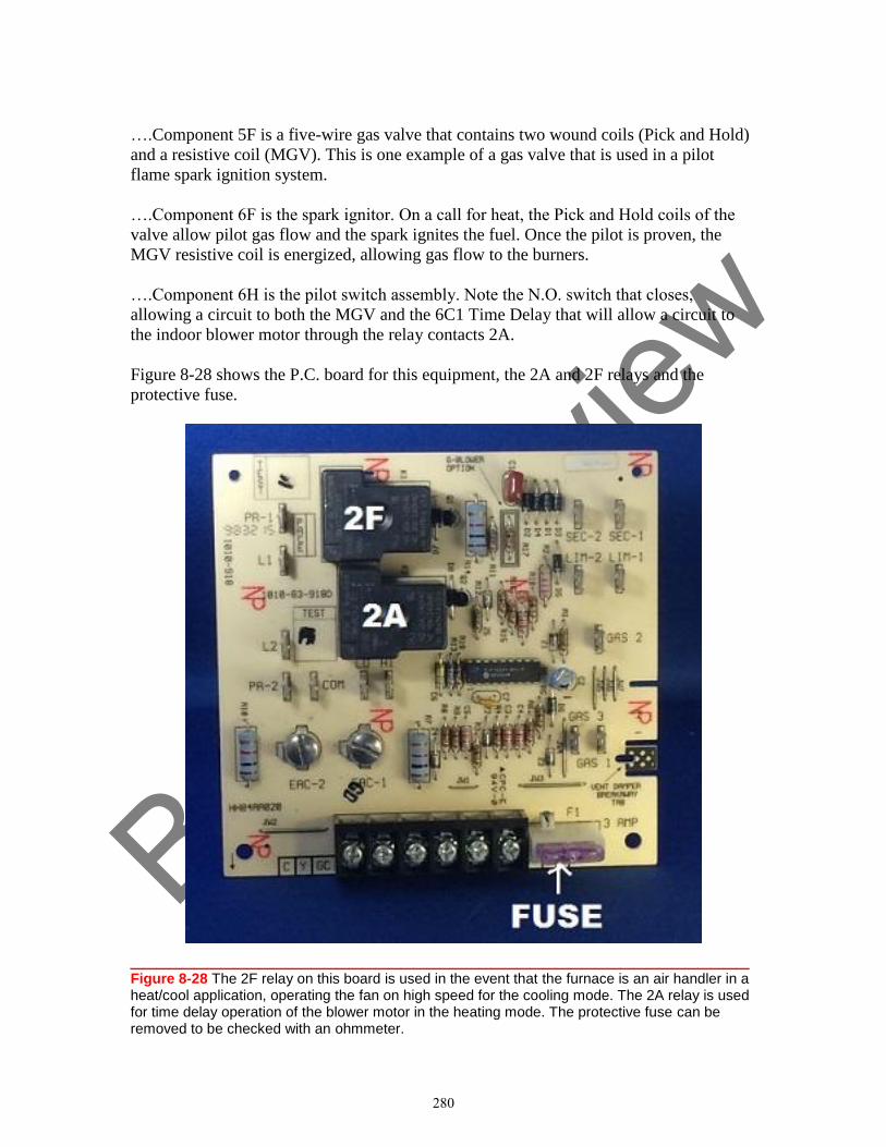
Book P
review
….Component 5F is a five-wire gas valve that contains two wound coils (Pick and Hold)
and a resistive coil (MGV). This is one example of a gas valve that is used in a pilot
flame spark ignition system.
….Component 6F is the spark ignitor. On a call for heat, the Pick and Hold coils of the
valve allow pilot gas flow and the spark ignites the fuel. Once the pilot is proven, the
MGV resistive coil is energized, allowing gas flow to the burners.
….Component 6H is the pilot switch assembly. Note the N.O. switch that closes,
allowing a circuit to both the MGV and the 6C1 Time Delay that will allow a circuit to
the indoor blower motor through the relay contacts 2A.
Figure 8-28 shows the P.C. board for this equipment, the 2A and 2F relays and the
protective fuse.
________________________________________________ Figure 8-28 The 2F relay on this board is used in the event that the furnace is an air handler in a heat/cool application, operating the fan on high speed for the cooling mode. The 2A relay is used for time delay operation of the blower motor in the heating mode. The protective fuse can be removed to be checked with an ohmmeter.
280
Book P
review
UNIT
9
Wiring Diagram Review: Comfort Cooling & Refrigeration Systems
Learning Objectives:
After studying this unit, you will be able to:
1. Read a typical schematic for comfort cooling and refrigeration systems and
explain the sequence of operation.
2. Isolate circuits on schematic diagrams to accomplish troubleshooting procedures.
3. Identify hot gas and electric defrost circuits in refrigeration equipment.
This unit provides an overview of dual-voltage schematic diagrams for comfort cooling
systems and refrigeration systems such as those found in light commercial applications
that do not employ step-down transformers for control purposes.
Typical comfort cooling equipment in residential and light commercial applications are
commonly single-phase operation, employing compressor motors that operate with
potential relays, run and start capacitors, and indoor and outdoor fan motors that are PSC
operation. In some commercial applications, the power supply is three-phase, which
means that the motors will not operate in conjunction with capacitors.
Regardless of the equipment supply voltage, comfort cooling electrical systems are
represented by dual-voltage schematic diagrams that are designed from the symbol for
the schematic, showing the equipment voltage for operating motors, and 24-volt control
voltage systems that employ thermostats, coils, and other devices to protect and operate
the equipment. ECM technology (variable speed motors) is also common in regard to
both indoor and outdoor air handling for comfort cooling equipment.
Electrical systems for refrigeration equipment found in walk-in coolers and freezers,
reach-in equipment, and ice machines may or may not employ the dual-voltage system
for operation and control, depending on the equipment design. Some equipment in this
category may employ ECM technology for air handling.
293
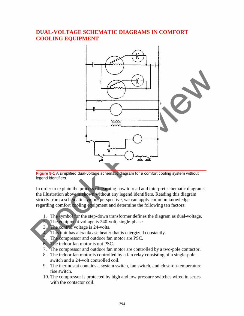
Book P
review
DUAL-VOLTAGE SCHEMATIC DIAGRAMS IN COMFORT
COOLING EQUIPMENT
________________________________________________ Figure 9-1 A simplified dual-voltage schematic diagram for a comfort cooling system without legend identifiers.
In order to explain the process of learning how to read and interpret schematic diagrams,
the illustration above is shown without any legend identifiers. Reading this diagram
strictly from a schematic symbol perspective, we can apply common knowledge
regarding comfort cooling equipment and determine the following ten factors:
1. The symbol for the step-down transformer defines the diagram as dual-voltage.
2. The equipment voltage is 240-volt, single-phase.
3. The control voltage is 24-volts.
4. This unit has a crankcase heater that is energized constantly.
5. The compressor and outdoor fan motor are PSC.
6. The indoor fan motor is not PSC.
7. The compressor and outdoor fan motor are controlled by a two-pole contactor.
8. The indoor fan motor is controlled by a fan relay consisting of a single-pole
switch and a 24-volt controlled coil.
9. The thermostat contains a system switch, fan switch, and close-on-temperature
rise switch.
10. The compressor is protected by high and low pressure switches wired in series
with the contactor coil.
294
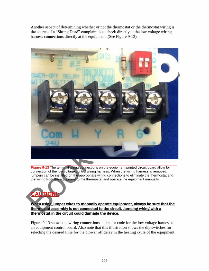
Book P
review
Another aspect of determining whether or not the thermostat or the thermostat wiring is
the source of a “Sitting Dead” complaint is to check directly at the low voltage wiring
harness connections directly at the equipment. (See Figure 9-13)
________________________________________________ Figure 9-13 The terminal wiring connections on the equipment printed circuit board allow for connection of the low voltage control wiring harness. When the wiring harness is removed, jumpers can be installed on the appropriate wiring connections to eliminate the thermostat and the wiring from the equipment to the thermostat and operate the equipment manually.
CAUTION!:
When using jumper wires to manually operate equipment, always be sure that the
thermostat assembly is not connected to the circuit. Jumping wiring with a
thermostat in the circuit could damage the device.
Figure 9-13 shows the wiring connections and color code for the low voltage harness to
an equipment control board. Also note that this illustration shows the dip switches for
selecting the desired time for the blower off delay in the heating cycle of the equipment.
306
Book P
review
UNIT
10
Wiring Diagram Review: Heat Pumps
Learning Objectives:
After studying this unit, you will be able to:
1. Identify the three operating modes of a heat pump electrical system.
2. Explain the fundamental troubleshooting procedures that apply to heat pump
defrost control operation.
This unit focuses on the electrical circuits in heat pumps that allow the equipment to cool
and heat a conditioned space, employing both a refrigeration system, and when necessary
for the heating and defrost modes, supplemental electric heating elements.
As with comfort standard heating and cooling equipment and refrigeration systems, the
dual-voltage schematic diagram that shows the applied equipment voltage and a 24 VAC
control system is a key element in explaining the operation of heat pump components and
the sequence of operation of the equipment, providing the technician with the information
necessary in order to troubleshoot.
317
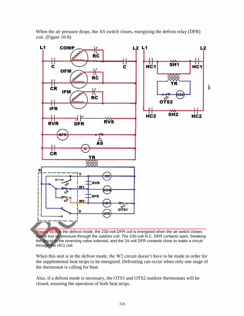
Book P
review
When the air pressure drops, the AS switch closes, energizing the defrost relay (DFR)
coil. (Figure 10-8)
________________________________________________ Figure 10-8 In the defrost mode, the 230-volt DFR coil is energized when the air switch closes due to low air pressure through the outdoor coil. The 230-volt N.C. DFR contacts open, breaking the circuit to the reversing valve solenoid, and the 24-volt DFR contacts close to make a circuit through the HC1 coil.
When this unit is in the defrost mode, the W2 circuit doesn’t have to be made in order for
the supplemental heat strips to be energized. Defrosting can occur when only one stage of
the thermostat is calling for heat.
Also, if a defrost mode is necessary, the OTS1 and OTS2 outdoor thermostats will be
closed, ensuring the operation of both heat strips.
326
Book P
review
HVACR Troubleshooting Fundamentals
Electricity and Wiring Diagrams
Appendix
A
Troubleshooting Problems
Student Review and Workbook Pages
Appendix A contains a series of troubleshooting problems in which various scenarios are
presented. In order to accomplish your diagnosis of the problems, you may be required to reread
sections of this book and complete additional research beyond what is found in this text.
Explain your diagnoses by filling in the blanks in your workbook pages at the end of
Appendix A.
341
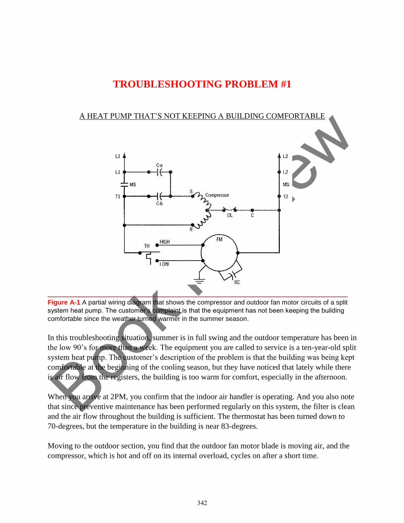
Book P
review
TROUBLESHOOTING PROBLEM #1
A HEAT PUMP THAT’S NOT KEEPING A BUILDING COMFORTABLE
___________________________________________________
Figure A-1 A partial wiring diagram that shows the compressor and outdoor fan motor circuits of a split
system heat pump. The customer’s complaint is that the equipment has not been keeping the building
comfortable since the weather turned warmer in the summer season.
In this troubleshooting situation, summer is in full swing and the outdoor temperature has been in
the low 90’s for more than a week. The equipment you are called to service is a ten-year-old split
system heat pump. The customer’s description of the problem is that the building was being kept
comfortable at the beginning of the cooling season, but they have noticed that lately while there
is air flow from the registers, the building is too warm for comfort, especially in the afternoon.
When you arrive at 2PM, you confirm that the indoor air handler is operating. And you also note
that since preventive maintenance has been performed regularly on this system, the filter is clean
and the air flow throughout the building is sufficient. The thermostat has been turned down to
70-degrees, but the temperature in the building is near 83-degrees.
Moving to the outdoor section, you find that the outdoor fan motor blade is moving air, and the
compressor, which is hot and off on its internal overload, cycles on after a short time.
342
Book P
review
(The diagram in Figure A-1 shows the circuitry for the compressor and outdoor fan motor of this
system.)
After a brief run time, the compressor again kicks off on overload.
In order to be sure that there is sufficient air flow you decide to check the outdoor fan motor
circuit. Your voltage check from T1 connection to HIGH on TH shows 240 VAC, and a test
from T1 to LOW shows 0-volts.
Your troubleshooting question: What is the next step you need to take in servicing this
equipment?
Explain your answer by filling in the blank for Troubleshooting Problem #1 in your workbook
pages.
343
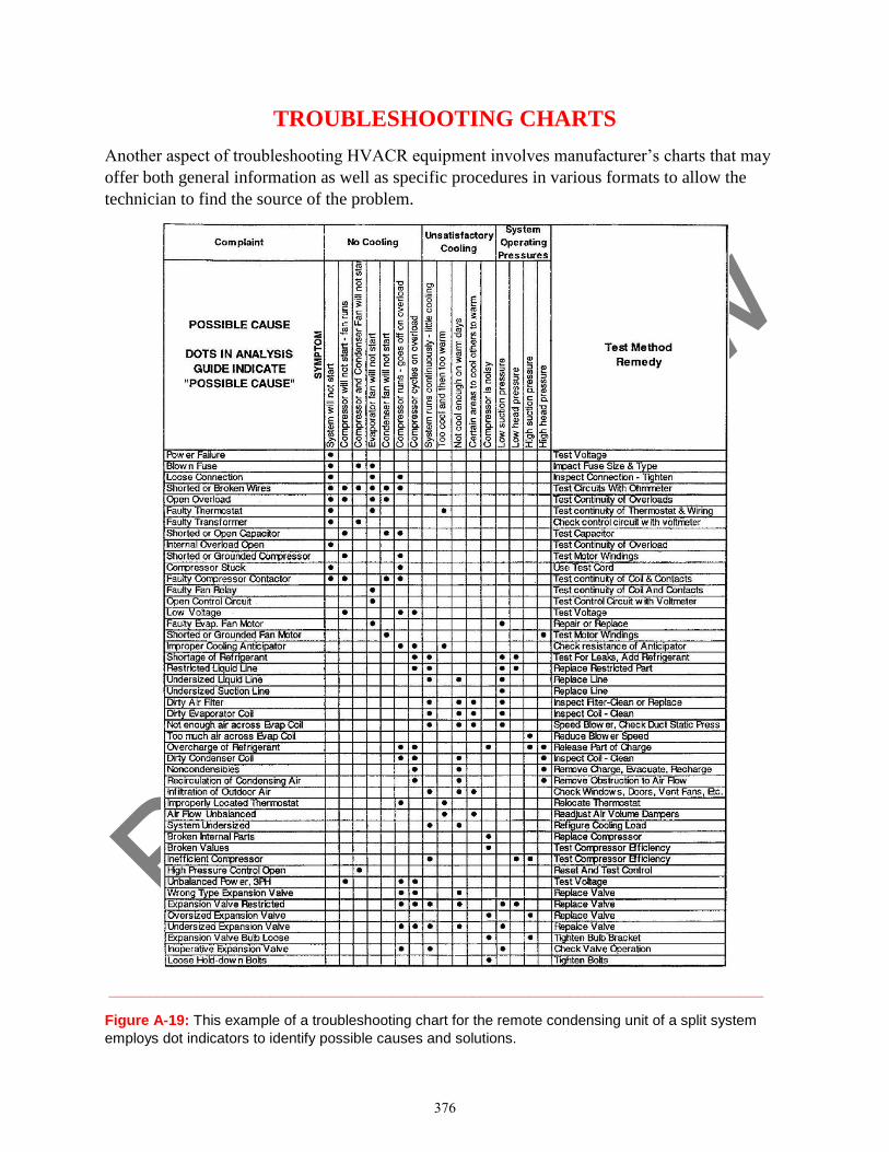
Book P
review
TROUBLESHOOTING CHARTS
Another aspect of troubleshooting HVACR equipment involves manufacturer’s charts that may
offer both general information as well as specific procedures in various formats to allow the
technician to find the source of the problem.
_________________________________________________________________________________
Figure A-19: This example of a troubleshooting chart for the remote condensing unit of a split system
employs dot indicators to identify possible causes and solutions.
376