technical training associates presents 20 hvacr...
TRANSCRIPT
Technical Training Associates
Presents
20 HVACR Troubleshooting Problems
Volume 2
By Jim Johnson
A Practical Approach To Troubleshooting HVACR Equipment
20 HVACR Troubleshooting Problems Volume 2 By Jim Johnson
Copyright © 2011 Technical Training Associates
HC 70 Box 3172
Sahuarita, AZ 85629
(520) 625-6847
www.techtrainassoc.com
All digital copyrights reserved. Permission is granted by the publisher to print and
photocopy the material herein for the purpose of conducting individual training
sessions. Distribution of hard copy versions to the public for sale, or digital
copying of any and all information contained herein is prohibited.
This troubleshooting handbook contains 20 separate troubleshooting scenarios
designed to test the skills of HVAC R technicians. In each situation, all the
information necessary to arrive at a diagnosis is provided.
The solutions to the problems are presented in a separate section at the end of the
book.
If you are working individually with this handbook, use it to test yourself. Review
the problem and any related graphics or wiring diagrams, then, record your
diagnosis before checking your answer in the solutions section.
If you are a serviced manager conducting in-house training sessions, or an
instructor facilitating a classroom or lab training exercise, you may print and
photocopy the problems and diagrams for classroom distribution. Digital copying
of this CD or electronic file is prohibited as noted in the copyright notice above.
Troubleshooting Problem #1
A SPLIT SYSTEM THAT‟S NOT KEEPING THE BUILDING
COMFORTABLE
We‟ll begin our explanation of this problem by saying there is a lot of
history with the seven-year-old residential system in this three bedroom, two bath
rental home, and the several technicians who have been there ahead of you have
suggested that the problem with this under-performing system could be a system
undercharge, kinked tubing in the wall, or a “slightly inefficient compressor”, and
all of the diagnosis up to this point has been accomplished by working with the
condensing unit only.
When you arrive, you decide to take a different approach to evaluating the
performance of this system and focus on the air handler and indoor coil in the attic.
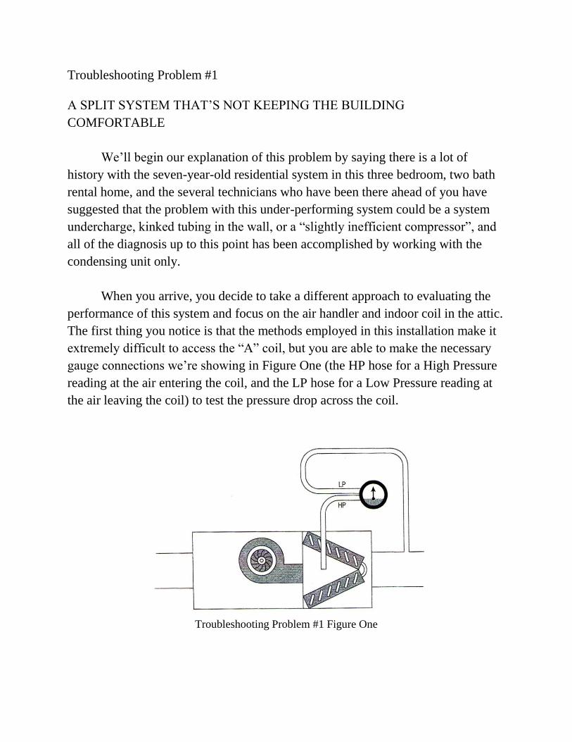
The first thing you notice is that the methods employed in this installation make it
extremely difficult to access the “A” coil, but you are able to make the necessary
gauge connections we‟re showing in Figure One (the HP hose for a High Pressure
reading at the air entering the coil, and the LP hose for a Low Pressure reading at
the air leaving the coil) to test the pressure drop across the coil.
Troubleshooting Problem #1 Figure One
After monitoring the operation of the system for several minutes you note
that your pressure test shows the drop being measured is 0.6 in. w.g.
Your troubleshooting question: What is the next step you need to take in
order to continue your evaluation of this equipment?
Troubleshooting Problem #2
A HEAT PUMP THAT WON‟T COOL
In this troubleshooting situation, the equipment you‟re servicing is a 240-
Volt, single-phase split system, and the customer‟s complaint is simply that there is
no cooling. They also tell the dispatcher that they had the same problem at the
beginning of the cooling season last year, at which time a part was replaced and the
unit operated OK until now. When you arrive, you find the while the indoor and
outdoor fan motors are operating, the root of the problem is that the compressor is
attempting to start, but kicks off on its overload. When you remove the access
panel, you check the schematic and note the wiring configuration for this
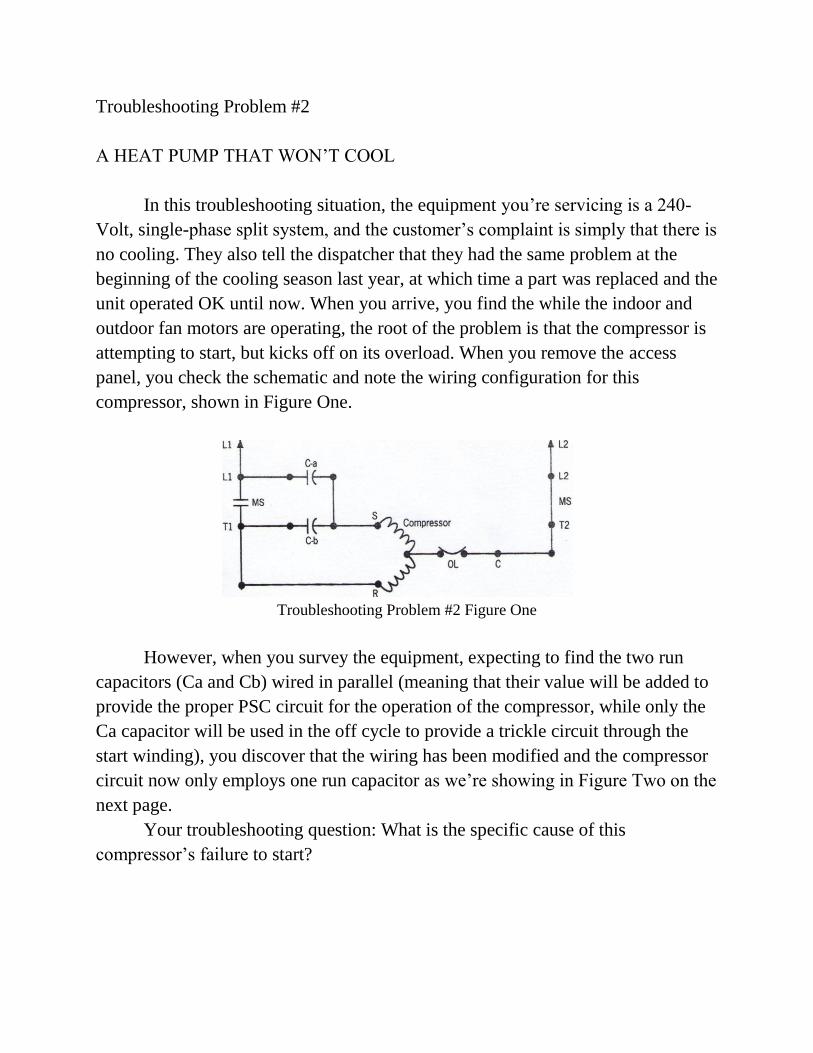
compressor, shown in Figure One.
Troubleshooting Problem #2 Figure One
However, when you survey the equipment, expecting to find the two run
capacitors (Ca and Cb) wired in parallel (meaning that their value will be added to
provide the proper PSC circuit for the operation of the compressor, while only the
Ca capacitor will be used in the off cycle to provide a trickle circuit through the
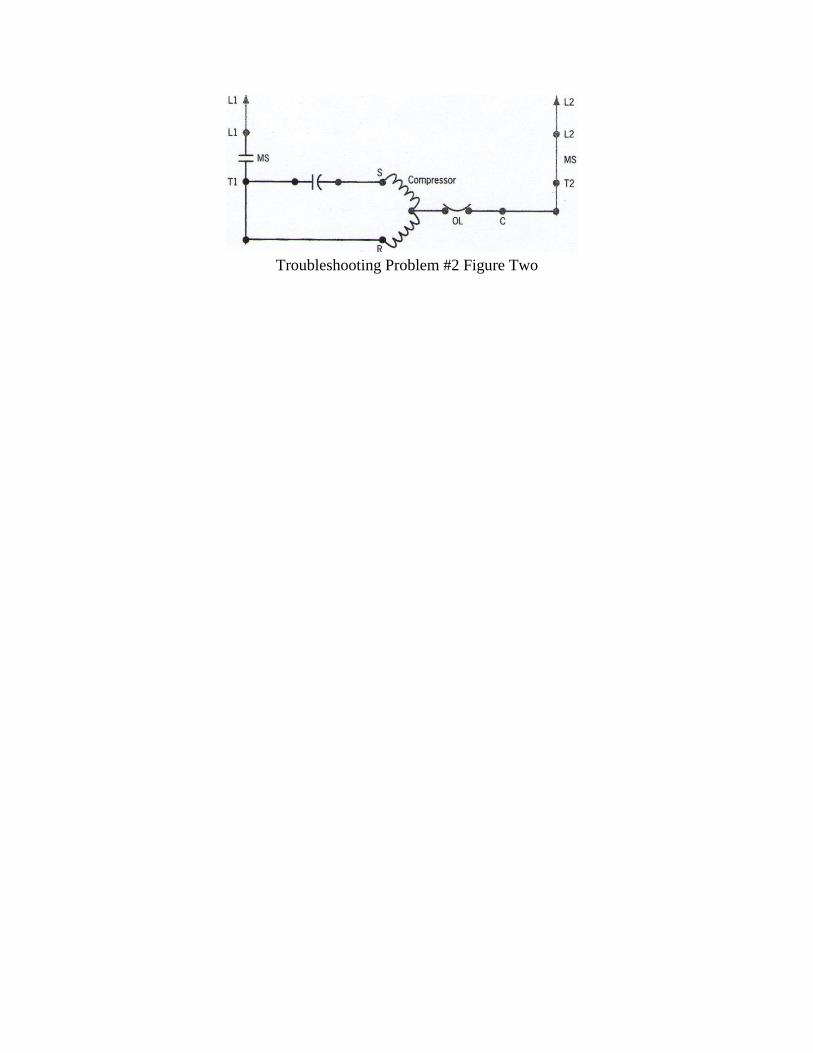
start winding), you discover that the wiring has been modified and the compressor
circuit now only employs one run capacitor as we‟re showing in Figure Two on the
next page.
Your troubleshooting question: What is the specific cause of this
compressor‟s failure to start?
Troubleshooting Problem #2 Figure Two
Troubleshooting Problem #3
A ROOFTOP UNIT THAT WON‟T SHUT DOWN
In this troubleshooting situation, it‟s winter, and our customer has called to
say that the older package unit that heats and cools their office is managing to
warm up the area, but then seems to cool down too much before providing heat
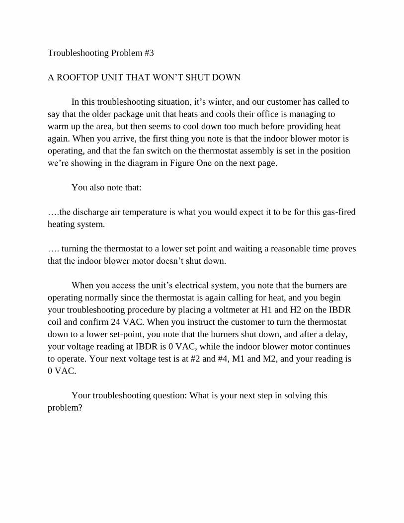
again. When you arrive, the first thing you note is that the indoor blower motor is
operating, and that the fan switch on the thermostat assembly is set in the position
we‟re showing in the diagram in Figure One on the next page.
You also note that:
….the discharge air temperature is what you would expect it to be for this gas-fired
heating system.
…. turning the thermostat to a lower set point and waiting a reasonable time proves
that the indoor blower motor doesn‟t shut down.
When you access the unit‟s electrical system, you note that the burners are
operating normally since the thermostat is again calling for heat, and you begin
your troubleshooting procedure by placing a voltmeter at H1 and H2 on the IBDR
coil and confirm 24 VAC. When you instruct the customer to turn the thermostat
down to a lower set-point, you note that the burners shut down, and after a delay,
your voltage reading at IBDR is 0 VAC, while the indoor blower motor continues
to operate. Your next voltage test is at #2 and #4, M1 and M2, and your reading is
0 VAC.
Your troubleshooting question: What is your next step in solving this
problem?
Troubleshooting Problem #3 Figure One
Troubleshooting Problem #4
A SECOND OPINION ON AN UNDERCOUNTER UNIT
This troubleshooting situation involves a small, two-door side-by-side unit that
allows for beverage storage in the right side compartment, and a small quantity of
frozen items on the left side compartment. The customer‟s original request for
service reported that both sections of the unit were warm.
This unit is compact, built-in under the counter in a tavern, and difficult to
access. The first technician to respond to this situation told the owner that he was
familiar with common failures of this unique equipment, and after a quick look and
observation of the operation of the unit (no meter tests), he explained to the
customer that the compressor needed to be replaced and that he would have to
order the necessary parts.
After the technician left, the customer called the office to request a second
opinion. When you arrive, you also determine that this unit employs a PSC-
operated hermetic compressor, fan-cooled condenser, and an evaporator fan motor
and defrost system to maintain temperature and air flow. And, like the first
technician, you determine quickly that air is circulating both inside and under the
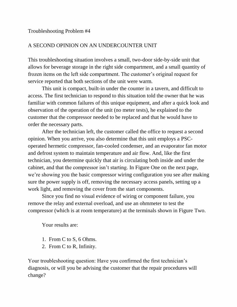
cabinet, and that the compressor isn‟t starting. In Figure One on the next page,
we‟re showing you the basic compressor wiring configuration you see after making
sure the power supply is off, removing the necessary access panels, setting up a
work light, and removing the cover from the start components.
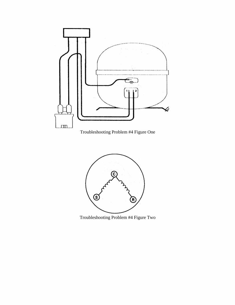
Since you find no visual evidence of wiring or component failure, you
remove the relay and external overload, and use an ohmmeter to test the
compressor (which is at room temperature) at the terminals shown in Figure Two.
Your results are:
1. From C to S, 6 Ohms.
2. From C to R, Infinity.
Your troubleshooting question: Have you confirmed the first technician‟s
diagnosis, or will you be advising the customer that the repair procedures will
change?
Troubleshooting Problem #4 Figure One
Troubleshooting Problem #4 Figure Two
Troubleshooting Problem #5
A MOTEL ROOM HEAT PUMP THAT‟S NOT HEATING
This troubleshooting problem is focused on one of those relatively rare situations
where you‟re called in to service a wall-through unit. The report from maintenance
personnel at the small motel is that the equipment is “blowing cool air when it‟s
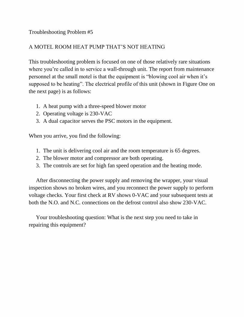
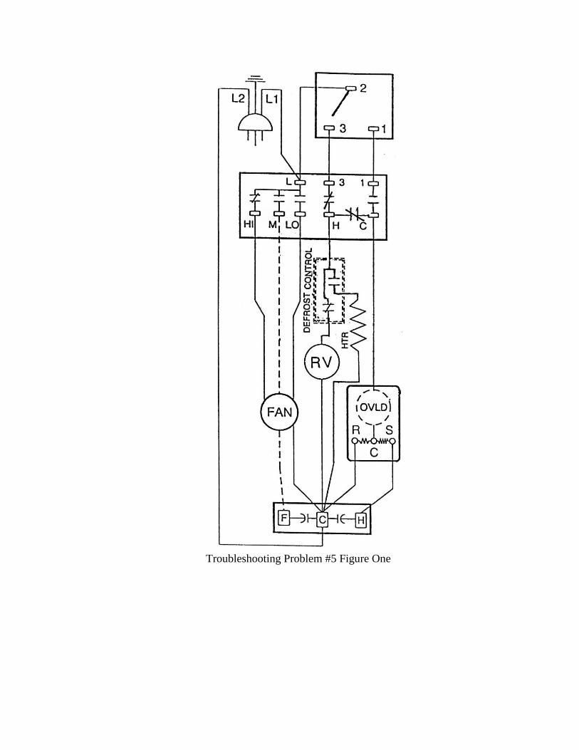
supposed to be heating”. The electrical profile of this unit (shown in Figure One on
the next page) is as follows:
1. A heat pump with a three-speed blower motor
2. Operating voltage is 230-VAC
3. A dual capacitor serves the PSC motors in the equipment.
When you arrive, you find the following:
1. The unit is delivering cool air and the room temperature is 65 degrees.
2. The blower motor and compressor are both operating.
3. The controls are set for high fan speed operation and the heating mode.
After disconnecting the power supply and removing the wrapper, your visual
inspection shows no broken wires, and you reconnect the power supply to perform
voltage checks. Your first check at RV shows 0-VAC and your subsequent tests at
both the N.O. and N.C. connections on the defrost control also show 230-VAC.
Your troubleshooting question: What is the next step you need to take in
repairing this equipment?
Troubleshooting Problem #5 Figure One
Troubleshooting Problem #6
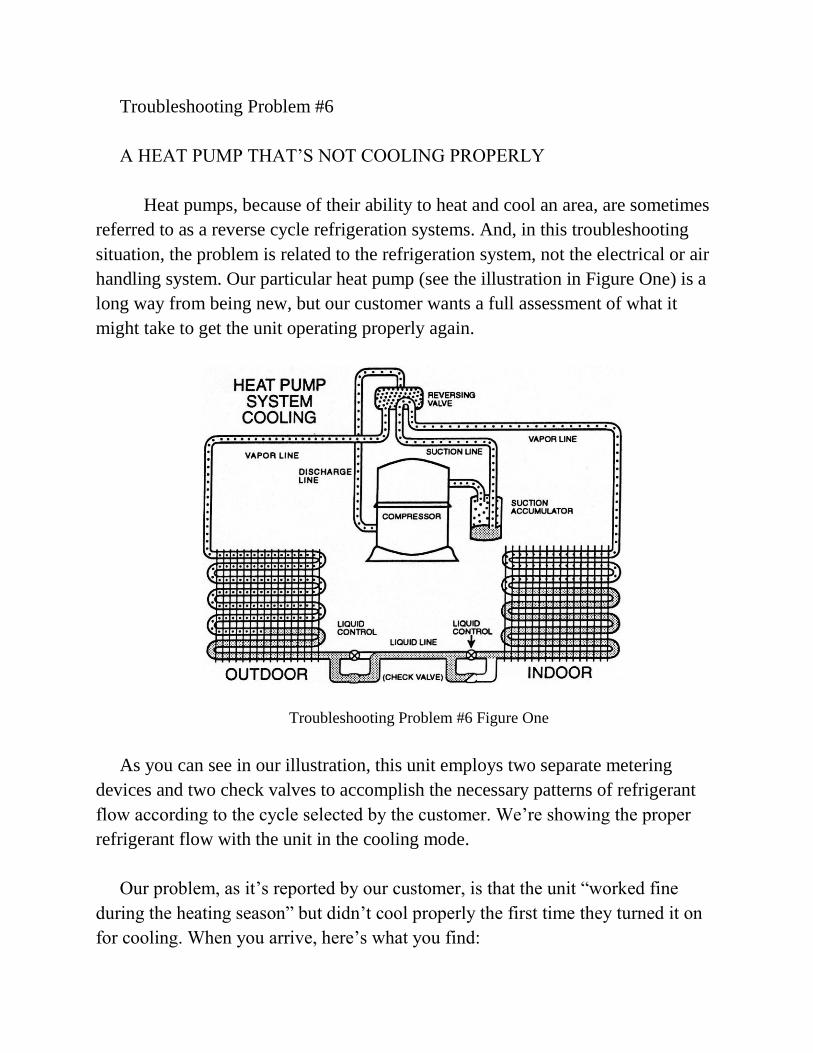
A HEAT PUMP THAT‟S NOT COOLING PROPERLY
Heat pumps, because of their ability to heat and cool an area, are sometimes
referred to as a reverse cycle refrigeration systems. And, in this troubleshooting
situation, the problem is related to the refrigeration system, not the electrical or air
handling system. Our particular heat pump (see the illustration in Figure One) is a
long way from being new, but our customer wants a full assessment of what it
might take to get the unit operating properly again.
Troubleshooting Problem #6 Figure One
As you can see in our illustration, this unit employs two separate metering
devices and two check valves to accomplish the necessary patterns of refrigerant
flow according to the cycle selected by the customer. We‟re showing the proper
refrigerant flow with the unit in the cooling mode.
Our problem, as it‟s reported by our customer, is that the unit “worked fine
during the heating season” but didn‟t cool properly the first time they turned it on
for cooling. When you arrive, here‟s what you find:
1. The compressor, outdoor fan motor and indoor fan motor are running, but
there is little cooling taking place.
2. The suction pressure is high.
3. Liquid subcooling is zero.
4. Liquid refrigerant is flooding back to the reversing valve, accumulator, and
compressor.
Your troubleshooting question: Which refrigeration system component is the
source of the problem?
Troubleshooting Problem #7
A SODA VENDING MACHINE THAT‟S NOT PERFORMING
PROPERLY…SOMETIMES
Author’s note….Your “hint” relative to this particular troubleshooting problem is
to remember the fundamental concept of maintaining a pressure differential in a
vapor compression system.
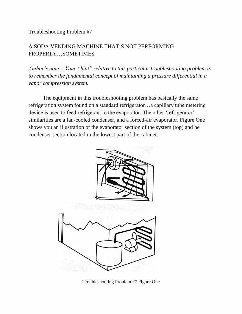
The equipment in this troubleshooting problem has basically the same
refrigeration system found on a standard refrigerator…a capillary tube metering
device is used to feed refrigerant to the evaporator. The other „refrigerator‟
similarities are a fan-cooled condenser, and a forced-air evaporator. Figure One
shows you an illustration of the evaporator section of the system (top) and he
condenser section located in the lowest part of the cabinet.
Troubleshooting Problem #7 Figure One
The complaint from the customer, who has positioned the unit outside their
small motel, is that while the soda seems to be properly cooled during the middle
of the day, there are times when the product is warmer than it should be.
Temperatures during the day are in the mid 70s, while the temperature later in the
day drops to the low 40s. When you make your initial stop early in the afternoon,
you note that the unit seems to be operating normally with both the evaporator and
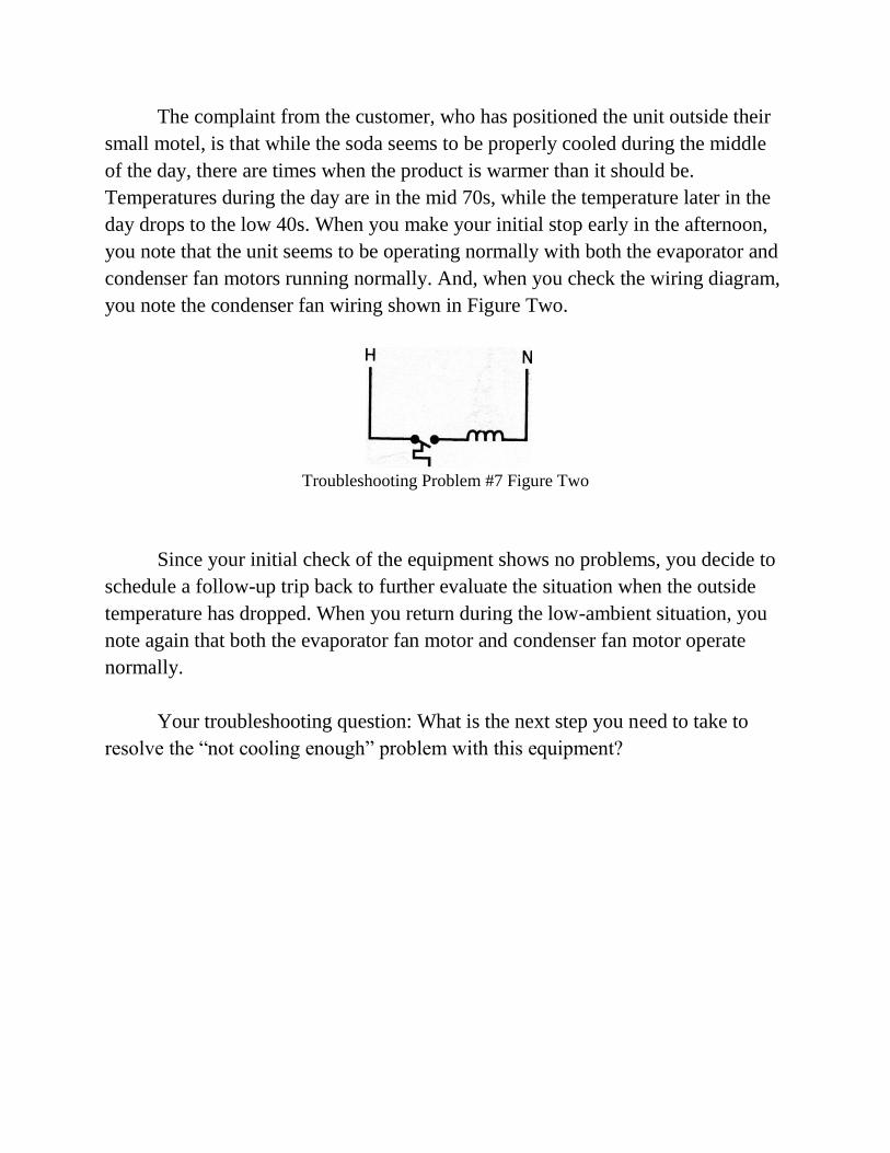
condenser fan motors running normally. And, when you check the wiring diagram,
you note the condenser fan wiring shown in Figure Two.
Troubleshooting Problem #7 Figure Two
Since your initial check of the equipment shows no problems, you decide to
schedule a follow-up trip back to further evaluate the situation when the outside
temperature has dropped. When you return during the low-ambient situation, you
note again that both the evaporator fan motor and condenser fan motor operate
normally.
Your troubleshooting question: What is the next step you need to take to
resolve the “not cooling enough” problem with this equipment?
Troubleshooting Problem #8
A SPLIT SYSTEM THAT‟S NOT COOLING
In this troubleshooting situation the equipment is a split system that‟s
approximately 5 years old, consisting of a gas furnace that provides heat in the
winter, and employs a condensing unit and “A” coil to provide summer cooling.
There are actually three questions to answer in this problem….two of them
regarding overall troubleshooting procedure, and the third one regarding the
necessary repair.
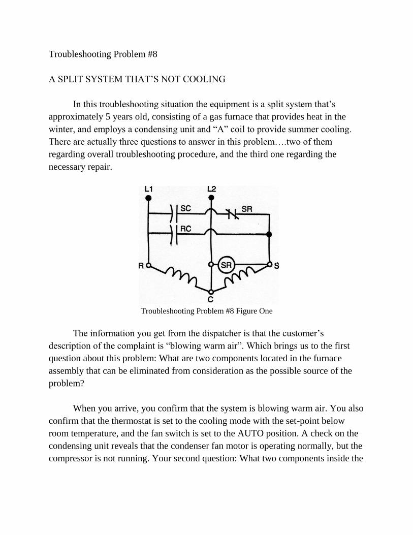
Troubleshooting Problem #8 Figure One
The information you get from the dispatcher is that the customer‟s
description of the complaint is “blowing warm air”. Which brings us to the first
question about this problem: What are two components located in the furnace
assembly that can be eliminated from consideration as the possible source of the
problem?
When you arrive, you confirm that the system is blowing warm air. You also
confirm that the thermostat is set to the cooling mode with the set-point below
room temperature, and the fan switch is set to the AUTO position. A check on the
condensing unit reveals that the condenser fan motor is operating normally, but the
compressor is not running. Your second question: What two components inside the
condensing unit can be eliminated from consideration as the source of the
problem?
After turning off the disconnect switch and removing the access cover, you
find that the compressor is hot to the touch, indicating it is attempting to start.
Based on that observation, you disconnect all the appropriate wiring when
necessary, and, with a digital meter, check the start components shown in Figure
One. And, you get the following results:
1. At terminals SC, you read the microfarad rating shown on the capacitor case.
2. At terminals RC, you read the microfarad rating shown on the capacitor
case.
3. At the SR terminals of the potential relay coil, infinity.
4. At the SR terminals of the potential relay switch, a fraction of an ohm.
Your final troubleshooting question: What do you have to do to get this unit
operating again?
Troubleshooting Problem #9
A 90-DEGREE OUTDOOR TEMPERATURE AND A CUSTOMER THAT‟S
HOT UNDER THE COLLAR
In this troubleshooting situation, it‟s the middle of summer, and our “hot
under the collar” customer is hot for two reasons: The temperature in their house is
uncomfortable, and you‟re following another technician who was there less than a
month ago in response to the same complaint, which is that the system is “blowing
warm air.”
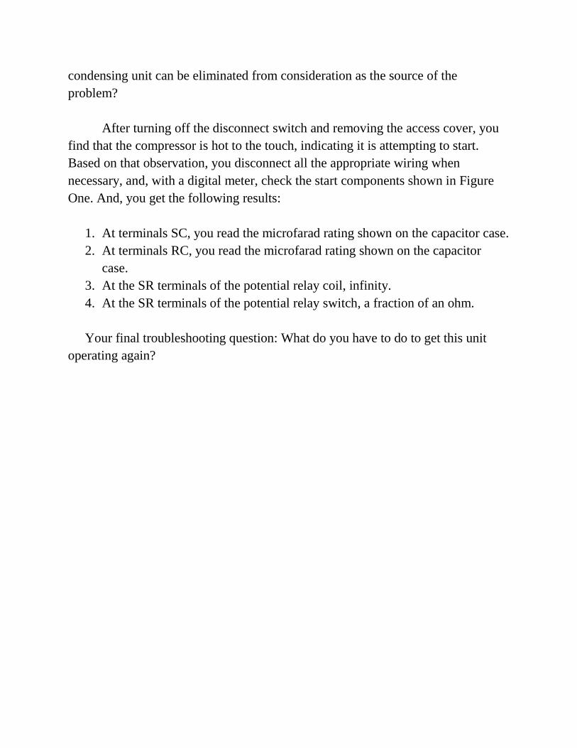
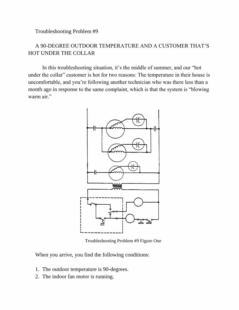
Troubleshooting Problem #9 Figure One
When you arrive, you find the following conditions:
1. The outdoor temperature is 90-degrees.
2. The indoor fan motor is running.
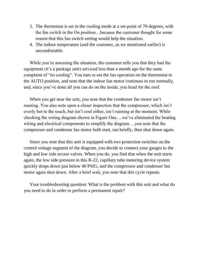
3. The thermostat is set in the cooling mode at a set-point of 70-degrees, with
the fan switch in the On position…because the customer thought for some
reason that this fan switch setting would help the situation.
4. The indoor temperature (and the customer, as we mentioned earlier) is
uncomfortable.
While you‟re assessing the situation, the customer tells you that they had the
equipment (it‟s a package unit) serviced less than a month ago for the same
complaint of “no cooling”. You turn re-set the fan operation on the thermostat to
the AUTO position, and note that the indoor fan motor continues to run normally,
and, since you‟ve done all you can do on the inside, you head for the roof.
When you get near the unit, you note that the condenser fan motor isn‟t
running. You also note upon a closer inspection that the compressor, which isn‟t
overly hot to the touch, but isn‟t cool either, isn‟t running at the moment. While
checking the wiring diagram shown in Figure One….we‟ve eliminated the heating
wiring and electrical components to simplify the diagram….you note that the
compressor and condenser fan motor both start, run briefly, then shut down again.
Since you note that this unit is equipped with two protection switches on the
control voltage segment of the diagram, you decide to connect your gauges to the
high and low side access valves. When you do, you find that when the unit starts
again, the low side pressure in this R-22, capillary tube metering device system
quickly drops down just below 40 PSIG, and the compressor and condenser fan
motor again shut down. After a brief wait, you note that this cycle repeats.
Your troubleshooting question: What is the problem with this unit and what do
you need to do in order to perform a permanent repair?
Troubleshooting Problem #10
A FOLLOW UP SERVICE CALL ON A THREE-PHASE UNIT
In this troubleshooting situation, in which a customer‟s 7 ½ ton, three-phase
(compressor and indoor fan motor, that is) package unit “isn‟t cooling like it
should”, Technician Number One gets the call and responds. Upon his arrival, he
finds the unit not running at all. Following standard troubleshooting procedures, he
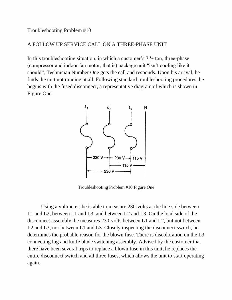
begins with the fused disconnect, a representative diagram of which is shown in
Figure One.
Troubleshooting Problem #10 Figure One
Using a voltmeter, he is able to measure 230-volts at the line side between
L1 and L2, between L1 and L3, and between L2 and L3. On the load side of the
disconnect assembly, he measures 230-volts between L1 and L2, but not between
L2 and L3, nor between L1 and L3. Closely inspecting the disconnect switch, he
determines the probable reason for the blown fuse. There is discoloration on the L3
connecting lug and knife blade switching assembly. Advised by the customer that
there have been several trips to replace a blown fuse in this unit, he replaces the
entire disconnect switch and all three fuses, which allows the unit to start operating
again.
The next day, a call comes through the dispatcher that the same customer is
calling to say that the unit “isn‟t cooling again” and, since you‟re closer to the
location, you pick up the call. When you arrive and go to the rooftop, you find the
following:
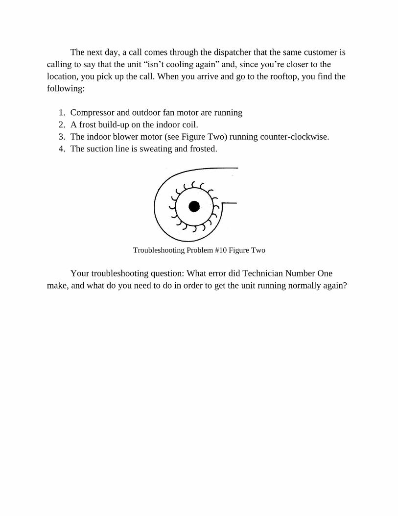
1. Compressor and outdoor fan motor are running
2. A frost build-up on the indoor coil.
3. The indoor blower motor (see Figure Two) running counter-clockwise.
4. The suction line is sweating and frosted.
Troubleshooting Problem #10 Figure Two
Your troubleshooting question: What error did Technician Number One
make, and what do you need to do in order to get the unit running normally again?
Troubleshooting Problem #11
A REFRIGERATION SYSTEM WITH A HISTORY OF COMPRESSOR
FAILURE
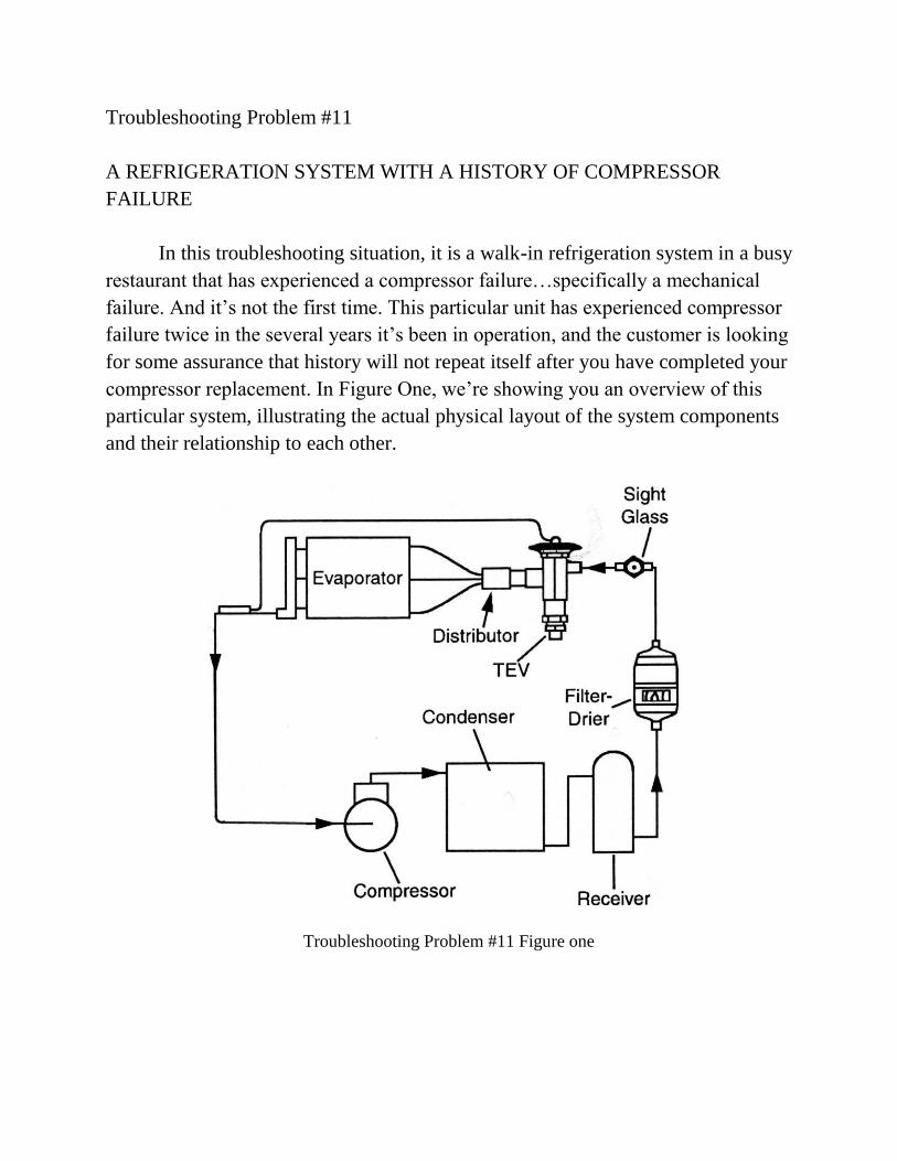
In this troubleshooting situation, it is a walk-in refrigeration system in a busy
restaurant that has experienced a compressor failure…specifically a mechanical
failure. And it‟s not the first time. This particular unit has experienced compressor
failure twice in the several years it‟s been in operation, and the customer is looking
for some assurance that history will not repeat itself after you have completed your
compressor replacement. In Figure One, we‟re showing you an overview of this
particular system, illustrating the actual physical layout of the system components
and their relationship to each other.
Troubleshooting Problem #11 Figure one
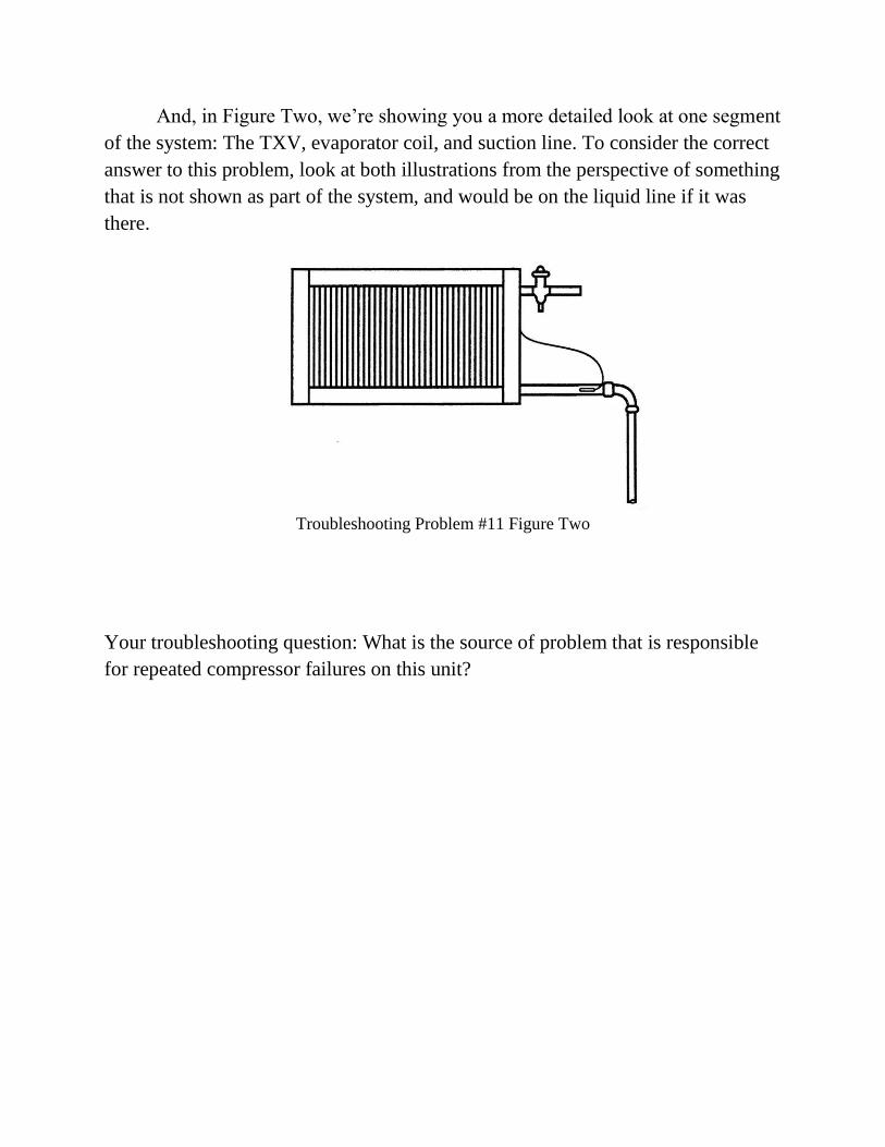
And, in Figure Two, we‟re showing you a more detailed look at one segment
of the system: The TXV, evaporator coil, and suction line. To consider the correct
answer to this problem, look at both illustrations from the perspective of something
that is not shown as part of the system, and would be on the liquid line if it was
there.
Troubleshooting Problem #11 Figure Two
Your troubleshooting question: What is the source of problem that is responsible
for repeated compressor failures on this unit?
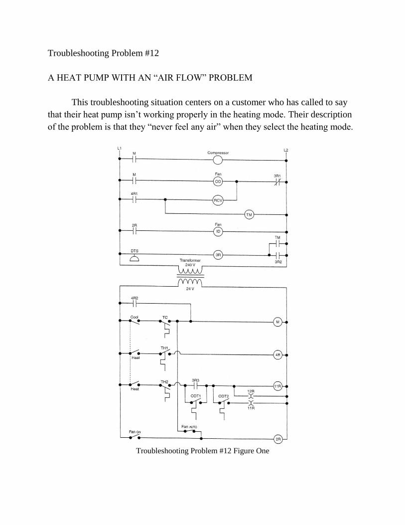
Troubleshooting Problem #12
A HEAT PUMP WITH AN “AIR FLOW” PROBLEM
This troubleshooting situation centers on a customer who has called to say
that their heat pump isn‟t working properly in the heating mode. Their description
of the problem is that they “never feel any air” when they select the heating mode.
Troubleshooting Problem #12 Figure One
Upon your arrival, you find the following conditions:
1. Thermostat turned off. (The customer thought it best to do that.)
2. Indoor temperature at 70 degrees.
When you set the thermostat system switch to the heating mode and make sure
that the set-point is above room temperature, you note that there is no indication of
air flow into the central return grille, which is nearby in the ceiling, just below this
rooftop package unit. What the customer called a “no air flow” problem, is, in
reality, a “no run” condition. When you switch the system switch to the cooling
mode and choose a set-point below room temperature, you note normal air flow
into the return.
With the thermostat is set back into the heating mode, you head to the roof and
remove the access panel. Using a voltmeter to accomplish the appropriate tests that
yield the following results: (Note the wiring diagram in Figure One)
1. 24-volts at 4R
2. 24 volts at 4R2
3. 240-volts at 4R1
Your two-part troubleshooting question: Which component has failed, and why
does the unit operate in the cooling mode, but not the heating mode?
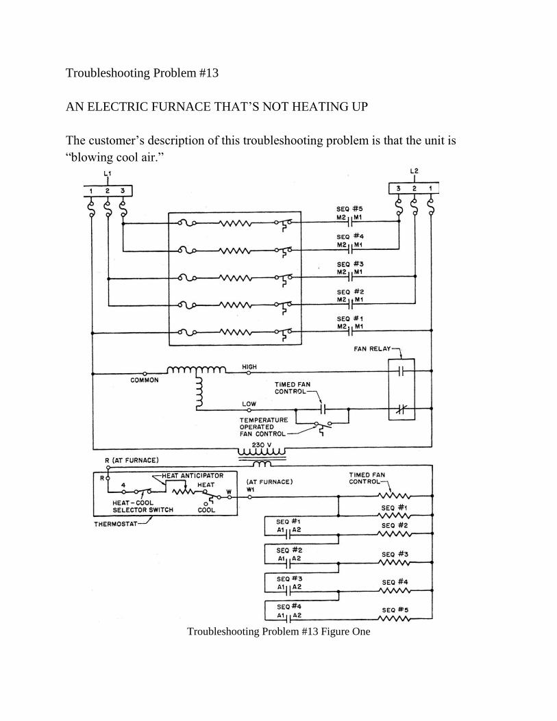
Troubleshooting Problem #13
AN ELECTRIC FURNACE THAT‟S NOT HEATING UP
The customer‟s description of this troubleshooting problem is that the unit is
“blowing cool air.”
Troubleshooting Problem #13 Figure One
This particular unit employs five heating elements that are energized in a
step fashion via five separate sequencers, as shown in Figure One.
Each individual element is protected by a fusible link (shown to the left of
each element) and an automatic re-set, over-temperature device (shown at the right
of each element). Each sequencer has a Main (M) set of N.O. ….Normally
Open…contacts, as well as an Auxiliary (A) set. The method of controlling each
sequencer is applying 24-volts to its control section, closing the M contacts first on
a time delay, then closing the A contacts on a subsequent delay.
Upon your arrival, you find the thermostat turned off and the system sitting
idle. Your first action is to turn the thermostat to the HEAT mode and leave the fan
switch in the AUTO position. After a slight delay, you note that the air handler
starts and operates at low speed. After allowing a reasonable time for the discharge
air temperature from a supply register to warm up, you note only a very slight rise
in temperature.
With the access panel removed, you use both an ammeter and a voltmeter to
evaluate the operation of the electrical system. With an ammeter clamped around
the L1 leg of element #1 (controlled by SEQ#1) you note a current draw of
approximately 15 amps. You also note a current draw of 0 amps when checking the
circuits of elements 2, 3, 4, and 5. With a voltmeter, you confirm the following
relative to sequencer #1:
1. 24-volts at the control section.
2. 0-volts at M1 and M2.
3. 24-volts at A1 and A2.
Your two-part troubleshooting question: Why is the unit heating air only
slightly, and which component needs to be replaced?
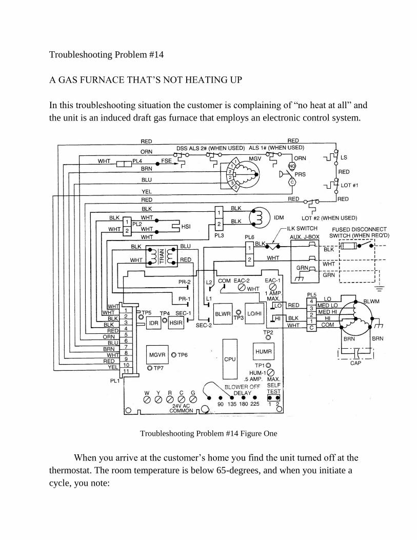
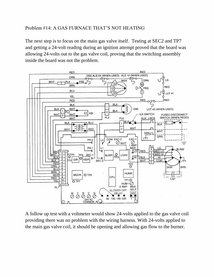
Troubleshooting Problem #14
A GAS FURNACE THAT‟S NOT HEATING UP
In this troubleshooting situation the customer is complaining of “no heat at all” and
the unit is an induced draft gas furnace that employs an electronic control system.
Troubleshooting Problem #14 Figure One
When you arrive at the customer‟s home you find the unit turned off at the
thermostat. The room temperature is below 65-degrees, and when you initiate a
cycle, you note:
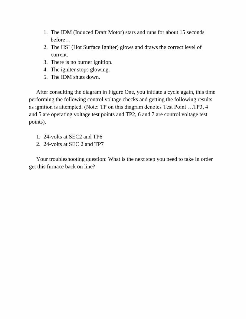
1. The IDM (Induced Draft Motor) stars and runs for about 15 seconds
before…
2. The HSI (Hot Surface Igniter) glows and draws the correct level of
current.
3. There is no burner ignition.
4. The igniter stops glowing.
5. The IDM shuts down.
After consulting the diagram in Figure One, you initiate a cycle again, this time
performing the following control voltage checks and getting the following results
as ignition is attempted. (Note: TP on this diagram denotes Test Point….TP3, 4
and 5 are operating voltage test points and TP2, 6 and 7 are control voltage test
points).
1. 24-volts at SEC2 and TP6
2. 24-volts at SEC 2 and TP7
Your troubleshooting question: What is the next step you need to take in order
get this furnace back on line?
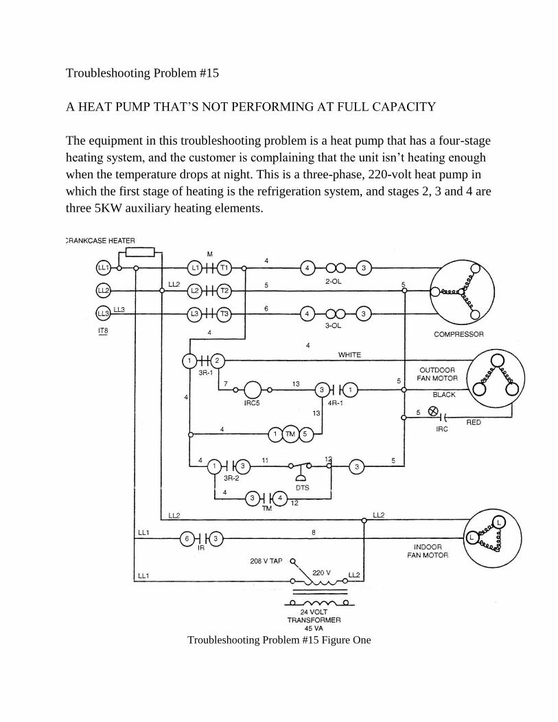
Troubleshooting Problem #15
A HEAT PUMP THAT‟S NOT PERFORMING AT FULL CAPACITY
The equipment in this troubleshooting problem is a heat pump that has a four-stage
heating system, and the customer is complaining that the unit isn‟t heating enough
when the temperature drops at night. This is a three-phase, 220-volt heat pump in
which the first stage of heating is the refrigeration system, and stages 2, 3 and 4 are
three 5KW auxiliary heating elements.
Troubleshooting Problem #15 Figure One
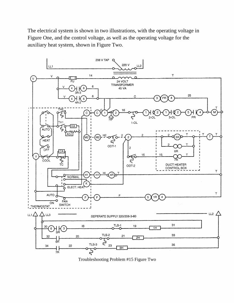
The electrical system is shown in two illustrations, with the operating voltage in
Figure One, and the control voltage, as well as the operating voltage for the
auxiliary heat system, shown in Figure Two.
Troubleshooting Problem #15 Figure Two
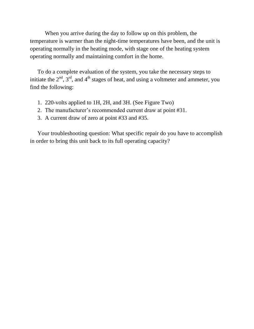
When you arrive during the day to follow up on this problem, the
temperature is warmer than the night-time temperatures have been, and the unit is
operating normally in the heating mode, with stage one of the heating system
operating normally and maintaining comfort in the home.
To do a complete evaluation of the system, you take the necessary steps to
initiate the 2nd
, 3rd
, and 4th stages of heat, and using a voltmeter and ammeter, you
find the following:
1. 220-volts applied to 1H, 2H, and 3H. (See Figure Two)
2. The manufacturer‟s recommended current draw at point #31.
3. A current draw of zero at point #33 and #35.
Your troubleshooting question: What specific repair do you have to accomplish
in order to bring this unit back to its full operating capacity?
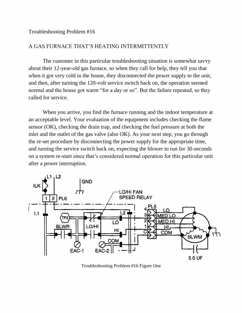
Troubleshooting Problem #16
A GAS FURNACE THAT‟S HEATING INTERMITTENTLY
The customer in this particular troubleshooting situation is somewhat savvy
about their 12-year-old gas furnace, so when they call for help, they tell you that
when it got very cold in the house, they disconnected the power supply to the unit,
and then, after turning the 120-volt service switch back on, the operation seemed
normal and the house got warm “for a day or so”. But the failure repeated, so they
called for service.
When you arrive, you find the furnace running and the indoor temperature at
an acceptable level. Your evaluation of the equipment includes checking the flame
sensor (OK), checking the drain trap, and checking the fuel pressure at both the
inlet and the outlet of the gas valve (also OK). As your next step, you go through
the re-set procedure by disconnecting the power supply for the appropriate time,
and turning the service switch back on, expecting the blower to run for 30-seconds
on a system re-start since that‟s considered normal operation for this particular unit
after a power interruption.
Troubleshooting Problem #16 Figure One
But the blower doesn‟t start until you hand-spin the squirrel cage. At this
point, you‟re leaning toward the diagnosis that the motor is failing (see the partial
diagram in Figure One), so you double-check two things: A test at the motor leads
from the printed circuit board shows 120-volts, and a check of the run capacitor
with your digital meter shows a reading of 2.5 microfarads.
Your troubleshooting question: Which component needs to be replaced?
Troubleshooting Problem #17
SIX HOUSES WITH THE SAME COMPLAINT
In this troubleshooting situation you‟ve been asked to investigate a problem
that‟s been ongoing since the gas furnaces were installed in six three-bedroom
homes. The compliant regarding each of them is the same: The back bedroom
doesn‟t get enough heat.
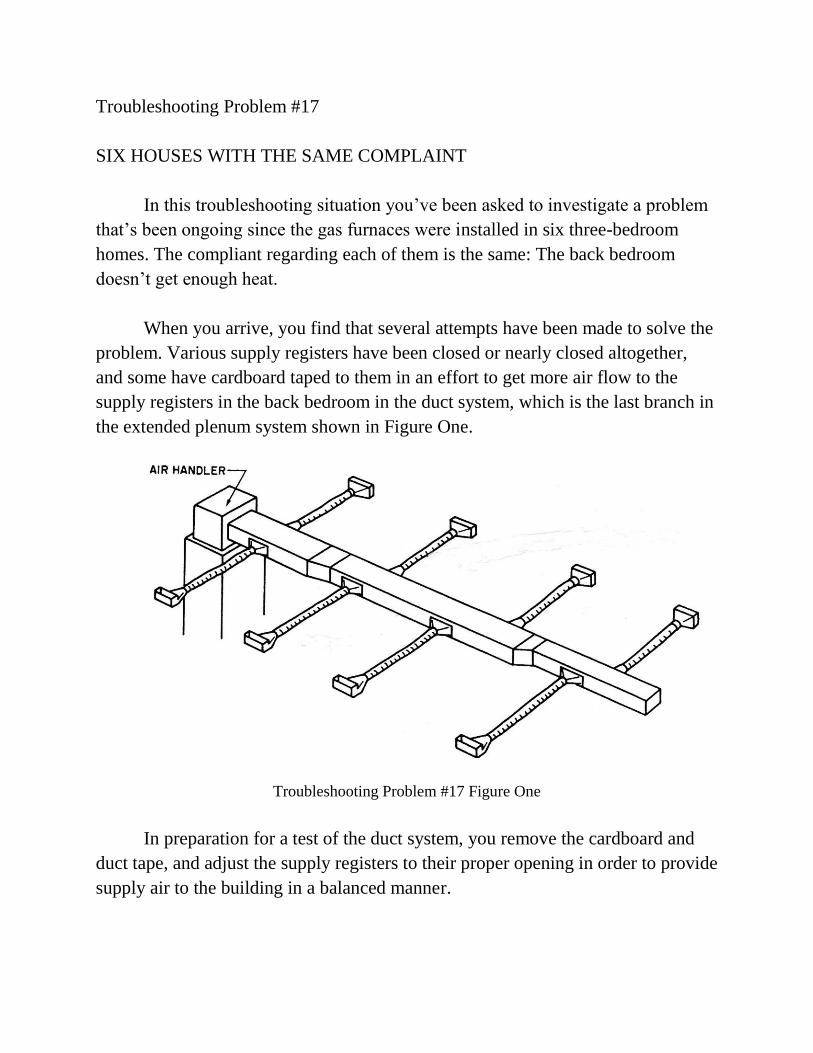
When you arrive, you find that several attempts have been made to solve the
problem. Various supply registers have been closed or nearly closed altogether,
and some have cardboard taped to them in an effort to get more air flow to the
supply registers in the back bedroom in the duct system, which is the last branch in
the extended plenum system shown in Figure One.
Troubleshooting Problem #17 Figure One
In preparation for a test of the duct system, you remove the cardboard and
duct tape, and adjust the supply registers to their proper opening in order to provide
supply air to the building in a balanced manner.
When you initiate a call for heat, you observe that the ignition system
functions and the main burner lights and burns correctly, and the 4-speed blower
motor operates on low speed. You also note that the equipment tag shows that the
temperature rise of this furnace should be 65-degrees. When you perform a
temperature rise test by checking the return air and supply air temperature you find
that the return temperature is 70-degrees and the supply temperature is 140-
degrees.
Your troubleshooting question: What installation error was committed that
prevented these furnaces from properly serving the back bedrooms?
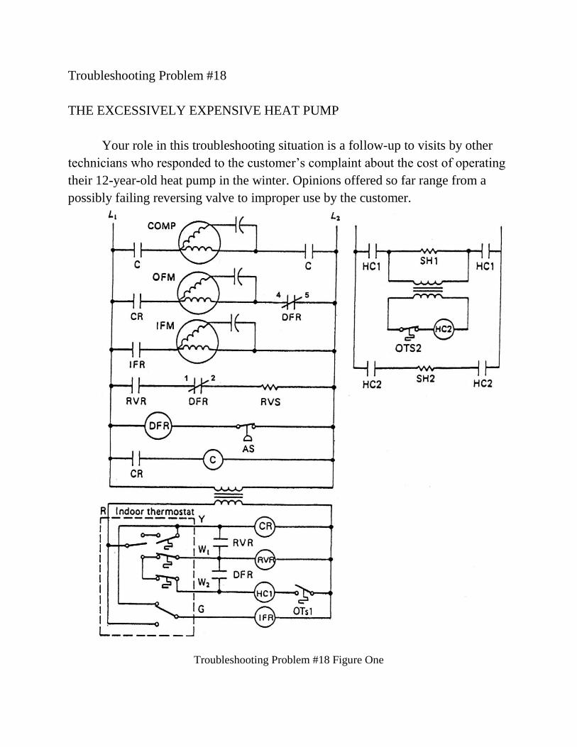
Troubleshooting Problem #18
THE EXCESSIVELY EXPENSIVE HEAT PUMP
Your role in this troubleshooting situation is a follow-up to visits by other
technicians who responded to the customer‟s complaint about the cost of operating
their 12-year-old heat pump in the winter. Opinions offered so far range from a
possibly failing reversing valve to improper use by the customer.
Troubleshooting Problem #18 Figure One
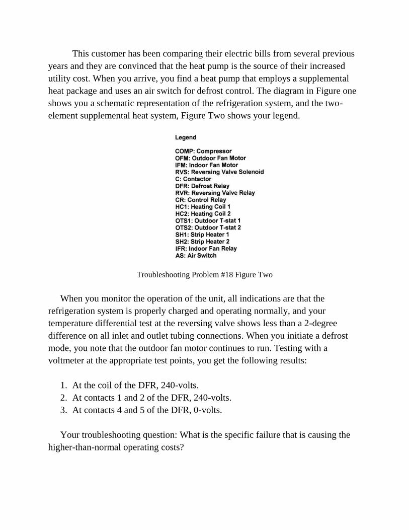
This customer has been comparing their electric bills from several previous
years and they are convinced that the heat pump is the source of their increased
utility cost. When you arrive, you find a heat pump that employs a supplemental
heat package and uses an air switch for defrost control. The diagram in Figure one
shows you a schematic representation of the refrigeration system, and the two-
element supplemental heat system, Figure Two shows your legend.
Troubleshooting Problem #18 Figure Two
When you monitor the operation of the unit, all indications are that the
refrigeration system is properly charged and operating normally, and your
temperature differential test at the reversing valve shows less than a 2-degree
difference on all inlet and outlet tubing connections. When you initiate a defrost
mode, you note that the outdoor fan motor continues to run. Testing with a
voltmeter at the appropriate test points, you get the following results:
1. At the coil of the DFR, 240-volts.
2. At contacts 1 and 2 of the DFR, 240-volts.
3. At contacts 4 and 5 of the DFR, 0-volts.
Your troubleshooting question: What is the specific failure that is causing the
higher-than-normal operating costs?
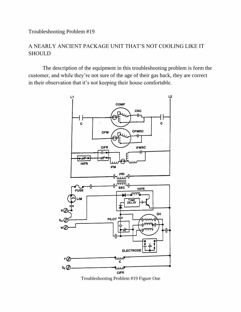
Troubleshooting Problem #19
A NEARLY ANCIENT PACKAGE UNIT THAT‟S NOT COOLING LIKE IT
SHOULD
The description of the equipment in this troubleshooting problem is form the
customer, and while they‟re not sure of the age of their gas back, they are correct
in their observation that it‟s not keeping their house comfortable.
Troubleshooting Problem #19 Figure One
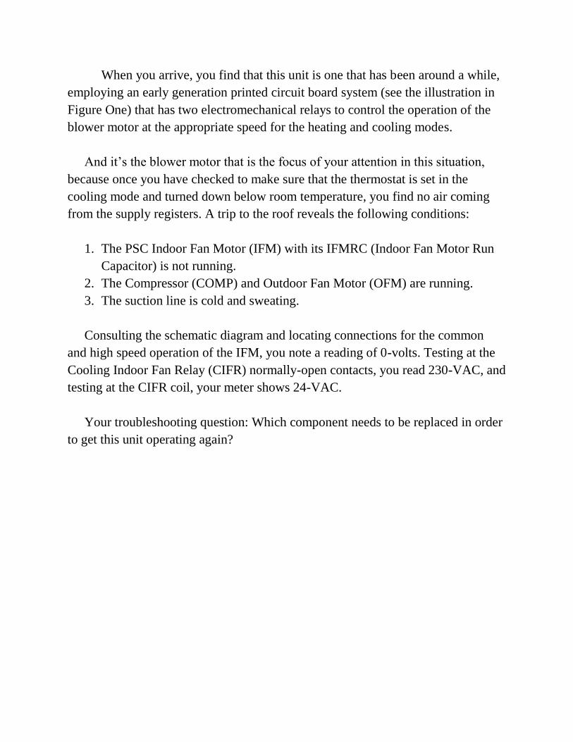
When you arrive, you find that this unit is one that has been around a while,
employing an early generation printed circuit board system (see the illustration in
Figure One) that has two electromechanical relays to control the operation of the
blower motor at the appropriate speed for the heating and cooling modes.
And it‟s the blower motor that is the focus of your attention in this situation,
because once you have checked to make sure that the thermostat is set in the
cooling mode and turned down below room temperature, you find no air coming
from the supply registers. A trip to the roof reveals the following conditions:
1. The PSC Indoor Fan Motor (IFM) with its IFMRC (Indoor Fan Motor Run
Capacitor) is not running.
2. The Compressor (COMP) and Outdoor Fan Motor (OFM) are running.
3. The suction line is cold and sweating.
Consulting the schematic diagram and locating connections for the common
and high speed operation of the IFM, you note a reading of 0-volts. Testing at the
Cooling Indoor Fan Relay (CIFR) normally-open contacts, you read 230-VAC, and
testing at the CIFR coil, your meter shows 24-VAC.
Your troubleshooting question: Which component needs to be replaced in order
to get this unit operating again?
Troubleshooting Problem #20
A WALK-IN FREEZER THAT‟S OPERATING ERATICALLY
In this troubleshooting situation you are dealing with equipment that has
only been in operation for two months. And during that time frame, the customer
has complained that at times the box temperature is higher than it should be, but
the unit them seems to recover and freeze OK until the next time some of the items
inside are found to be thawing.
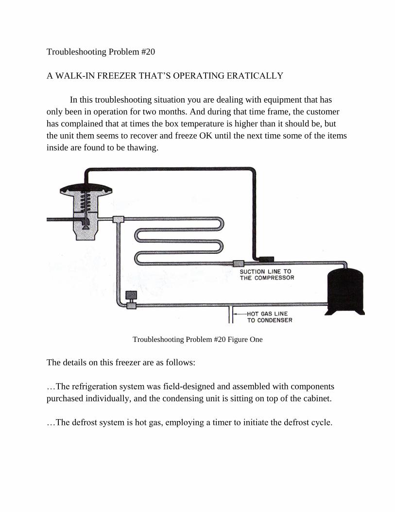
Troubleshooting Problem #20 Figure One
The details on this freezer are as follows:
…The refrigeration system was field-designed and assembled with components
purchased individually, and the condensing unit is sitting on top of the cabinet.
…The defrost system is hot gas, employing a timer to initiate the defrost cycle.
When you arrive to evaluate this equipment, you find all refrigerant
pressures to be normal and the box temperature is near 0-degrees. Satisfied that the
freezing mode of the unit is operating according to specifications, your next step is
to force a defrost mode.
When you do, you note that the evaporator fan motor shuts down and the hot
gas solenoid operates normally. Figure One shows you the path of refrigerant flow
during the hot gas defrost mode…from the got gas solenoid valve, directly through
the evaporator, and back to the compressor.
Near the end of the defrost mode, you find that the compressor kicks off on
overload, and isn‟t able to re-start until after an extended delay.
Your troubleshooting question: What mistake was made during the design
and construction of this system, causing the compressor to shut down?
TROUBLESHOOTING PROBLEM SOLUTIONS
Problem #1: A SPLIT SYSTEM THAT‟S NOT KEEPING THE BUILDING
COMFORTABLE
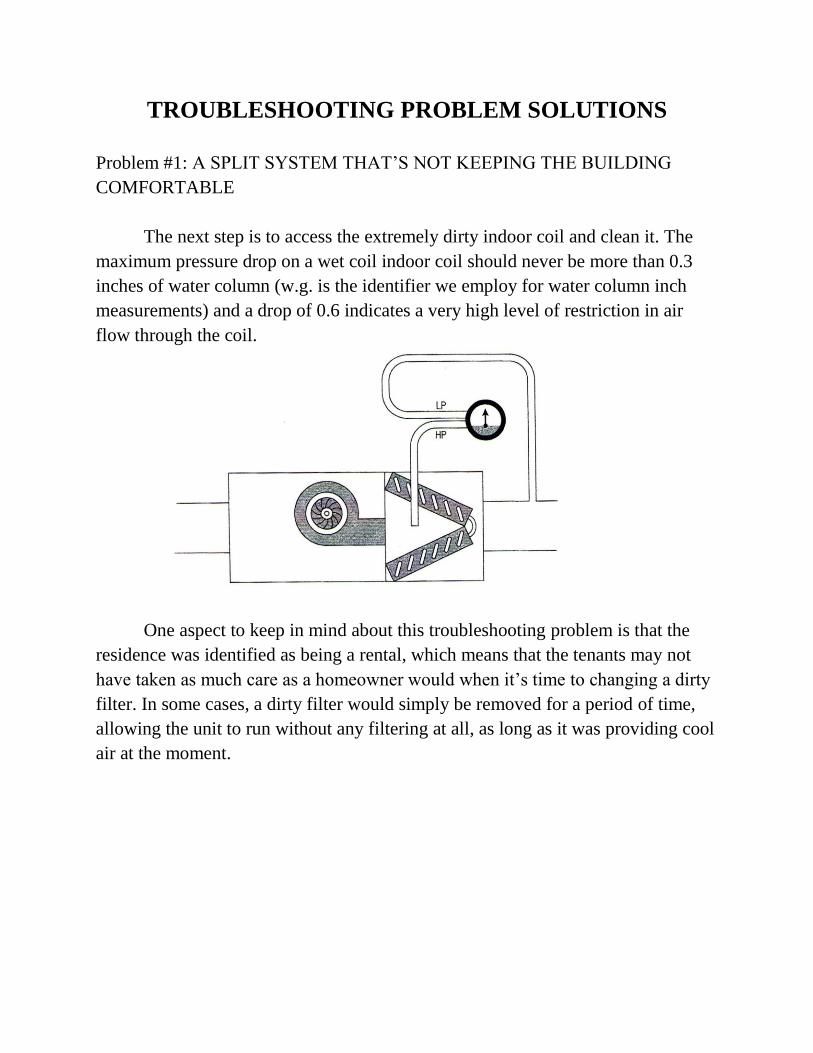
The next step is to access the extremely dirty indoor coil and clean it. The
maximum pressure drop on a wet coil indoor coil should never be more than 0.3
inches of water column (w.g. is the identifier we employ for water column inch
measurements) and a drop of 0.6 indicates a very high level of restriction in air
flow through the coil.
One aspect to keep in mind about this troubleshooting problem is that the
residence was identified as being a rental, which means that the tenants may not
have taken as much care as a homeowner would when it‟s time to changing a dirty
filter. In some cases, a dirty filter would simply be removed for a period of time,
allowing the unit to run without any filtering at all, as long as it was providing cool
air at the moment.
Problem #2: A HEAT PUMP THAT WON‟T COOL
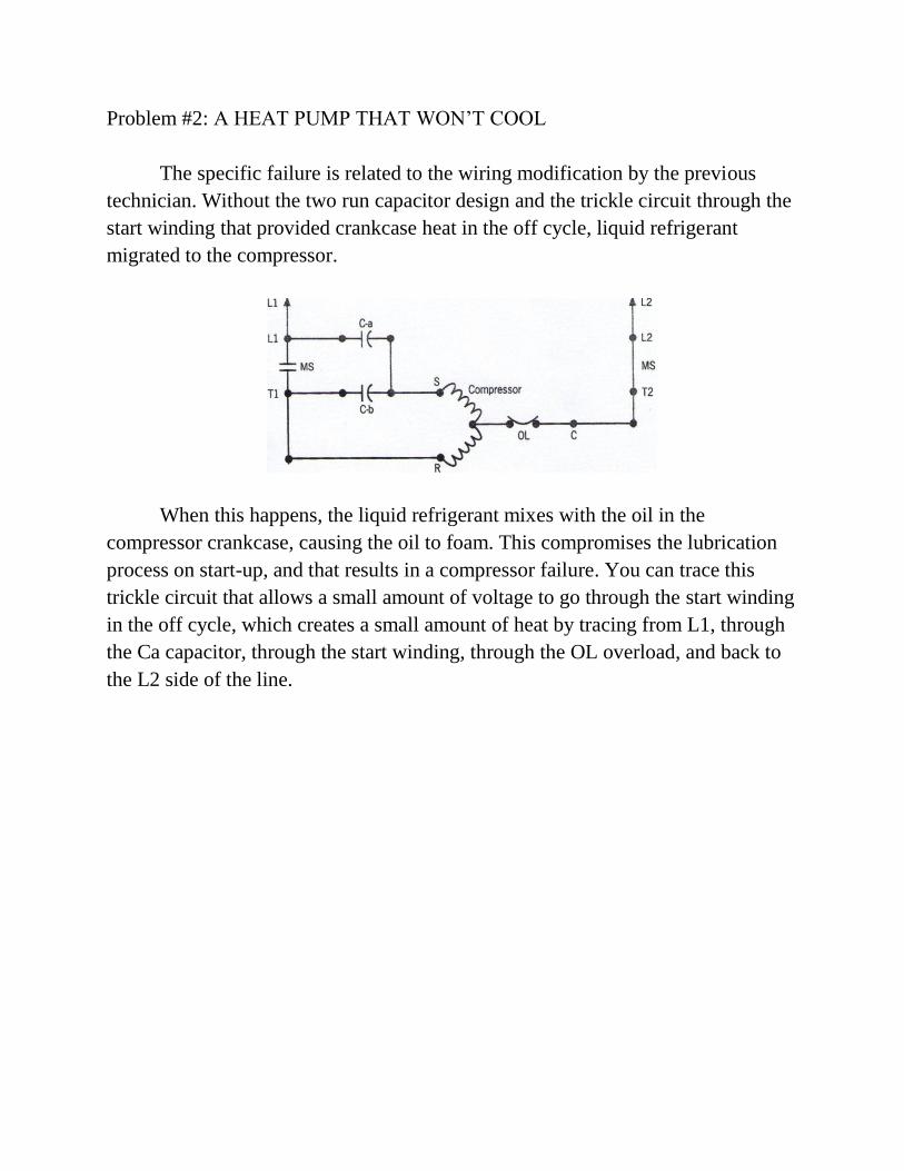
The specific failure is related to the wiring modification by the previous
technician. Without the two run capacitor design and the trickle circuit through the
start winding that provided crankcase heat in the off cycle, liquid refrigerant
migrated to the compressor.
When this happens, the liquid refrigerant mixes with the oil in the
compressor crankcase, causing the oil to foam. This compromises the lubrication
process on start-up, and that results in a compressor failure. You can trace this
trickle circuit that allows a small amount of voltage to go through the start winding
in the off cycle, which creates a small amount of heat by tracing from L1, through
the Ca capacitor, through the start winding, through the OL overload, and back to
the L2 side of the line.
Problem #3: A ROOFTOP UNIT THAT WON‟T SHUT DOWN
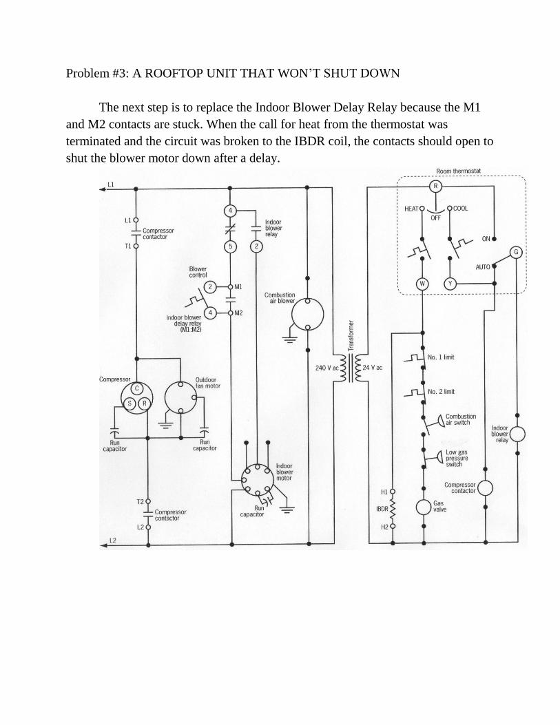
The next step is to replace the Indoor Blower Delay Relay because the M1
and M2 contacts are stuck. When the call for heat from the thermostat was
terminated and the circuit was broken to the IBDR coil, the contacts should open to
shut the blower motor down after a delay.
Problem #4: A SECOND OPINION ON AN UNDERCOUNTER UNIT
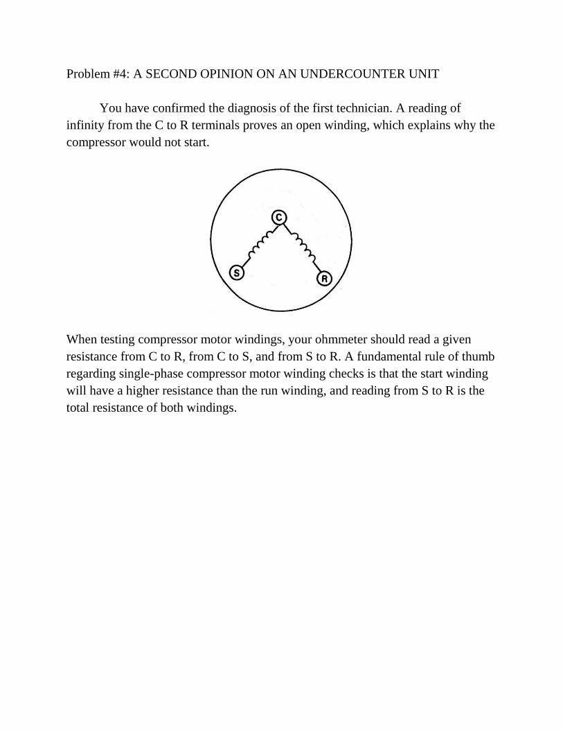
You have confirmed the diagnosis of the first technician. A reading of
infinity from the C to R terminals proves an open winding, which explains why the
compressor would not start.
When testing compressor motor windings, your ohmmeter should read a given
resistance from C to R, from C to S, and from S to R. A fundamental rule of thumb
regarding single-phase compressor motor winding checks is that the start winding
will have a higher resistance than the run winding, and reading from S to R is the
total resistance of both windings.
Problem #5: A MOTEL ROOM HEAT PUMP THAT‟S NOT HEATING
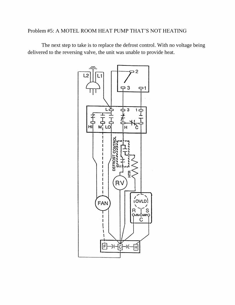
The next step to take is to replace the defrost control. With no voltage being
delivered to the reversing valve, the unit was unable to provide heat.
Problem #6: A HEAT PUMP THAT‟S NOT COOLING PROPERLY
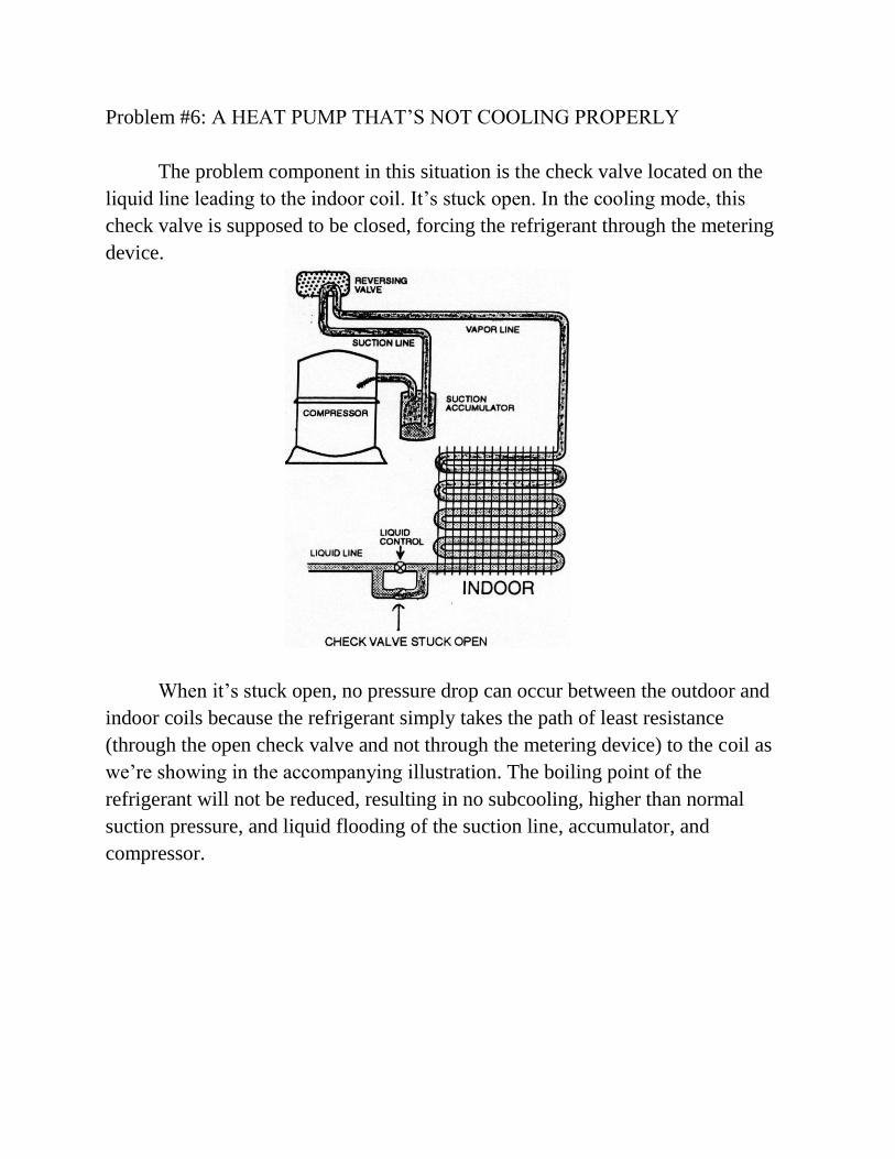
The problem component in this situation is the check valve located on the
liquid line leading to the indoor coil. It‟s stuck open. In the cooling mode, this
check valve is supposed to be closed, forcing the refrigerant through the metering
device.
When it‟s stuck open, no pressure drop can occur between the outdoor and
indoor coils because the refrigerant simply takes the path of least resistance
(through the open check valve and not through the metering device) to the coil as
we‟re showing in the accompanying illustration. The boiling point of the
refrigerant will not be reduced, resulting in no subcooling, higher than normal
suction pressure, and liquid flooding of the suction line, accumulator, and
compressor.
Problem #7: A SODA VENDING MACHINE THAT‟S NOT PERFORMING
PROPERLY…SOMETIMES
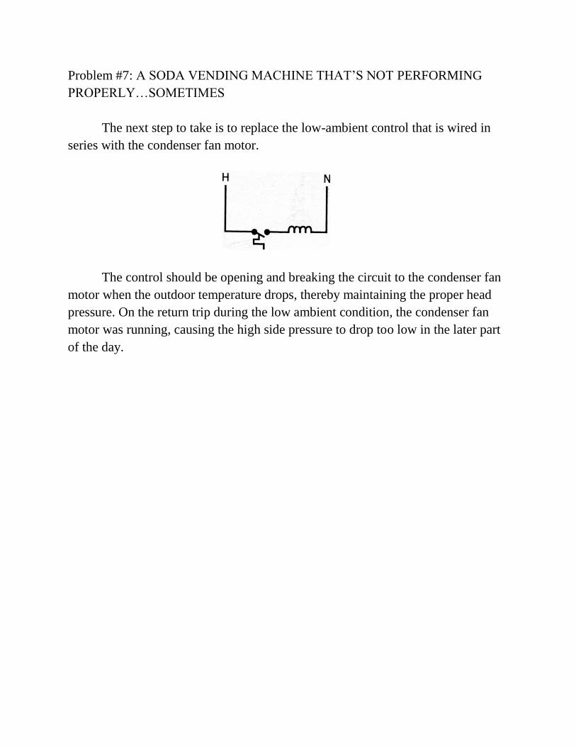
The next step to take is to replace the low-ambient control that is wired in
series with the condenser fan motor.
The control should be opening and breaking the circuit to the condenser fan
motor when the outdoor temperature drops, thereby maintaining the proper head
pressure. On the return trip during the low ambient condition, the condenser fan
motor was running, causing the high side pressure to drop too low in the later part
of the day.
Problem#8: A SPLIT SYSTEM THAT‟S NOT COOLING
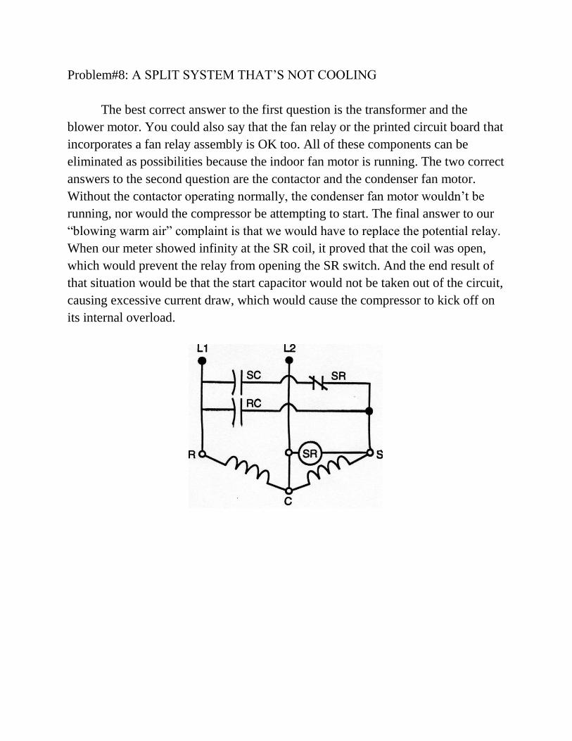
The best correct answer to the first question is the transformer and the
blower motor. You could also say that the fan relay or the printed circuit board that
incorporates a fan relay assembly is OK too. All of these components can be
eliminated as possibilities because the indoor fan motor is running. The two correct
answers to the second question are the contactor and the condenser fan motor.
Without the contactor operating normally, the condenser fan motor wouldn‟t be
running, nor would the compressor be attempting to start. The final answer to our
“blowing warm air” complaint is that we would have to replace the potential relay.
When our meter showed infinity at the SR coil, it proved that the coil was open,
which would prevent the relay from opening the SR switch. And the end result of
that situation would be that the start capacitor would not be taken out of the circuit,
causing excessive current draw, which would cause the compressor to kick off on
its internal overload.
Problem #9: A 90-DEGREE OUTDOOR TEMPERATURE AND A CUSTOMER
THAT‟S HOT UNDER THE COLLAR
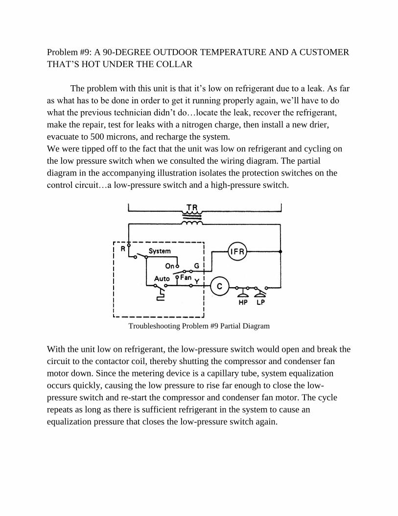
The problem with this unit is that it‟s low on refrigerant due to a leak. As far
as what has to be done in order to get it running properly again, we‟ll have to do
what the previous technician didn‟t do…locate the leak, recover the refrigerant,
make the repair, test for leaks with a nitrogen charge, then install a new drier,
evacuate to 500 microns, and recharge the system.
We were tipped off to the fact that the unit was low on refrigerant and cycling on
the low pressure switch when we consulted the wiring diagram. The partial
diagram in the accompanying illustration isolates the protection switches on the
control circuit…a low-pressure switch and a high-pressure switch.
Troubleshooting Problem #9 Partial Diagram
With the unit low on refrigerant, the low-pressure switch would open and break the
circuit to the contactor coil, thereby shutting the compressor and condenser fan
motor down. Since the metering device is a capillary tube, system equalization
occurs quickly, causing the low pressure to rise far enough to close the low-
pressure switch and re-start the compressor and condenser fan motor. The cycle
repeats as long as there is sufficient refrigerant in the system to cause an
equalization pressure that closes the low-pressure switch again.
Problem #10: A FOLLOW UP SERVICE CALL ON A THREE-PHASE UNIT
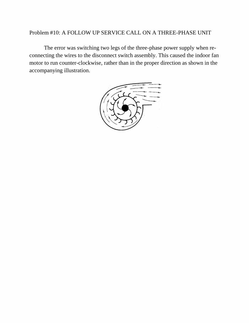
The error was switching two legs of the three-phase power supply when re-
connecting the wires to the disconnect switch assembly. This caused the indoor fan
motor to run counter-clockwise, rather than in the proper direction as shown in the
accompanying illustration.
Troubleshooting Problem #11: A REFRIGERATION SYSTEM WITH A
HISTORY OF COMPRESSOR FAILURE
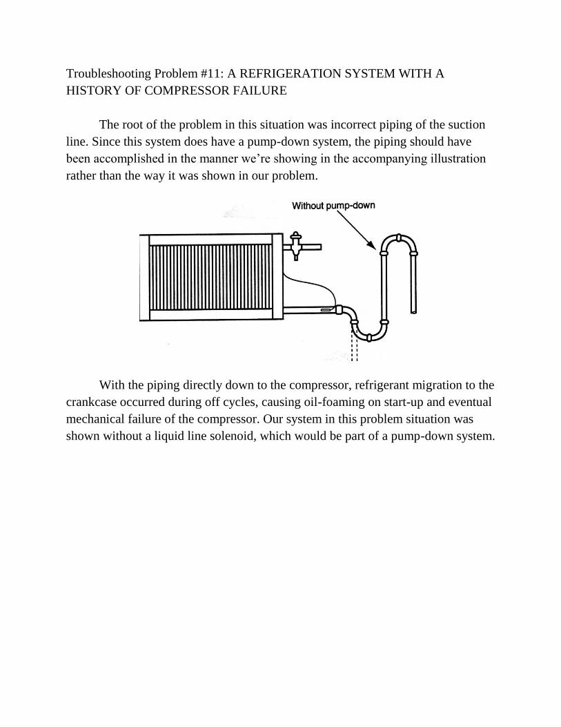
The root of the problem in this situation was incorrect piping of the suction
line. Since this system does have a pump-down system, the piping should have
been accomplished in the manner we‟re showing in the accompanying illustration
rather than the way it was shown in our problem.
With the piping directly down to the compressor, refrigerant migration to the
crankcase occurred during off cycles, causing oil-foaming on start-up and eventual
mechanical failure of the compressor. Our system in this problem situation was
shown without a liquid line solenoid, which would be part of a pump-down system.
Problem #12: A HEAT PUMP WITH AN “AIR FLOW” PROBLEM
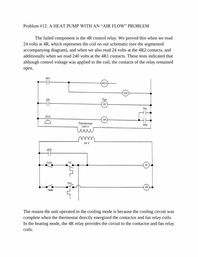
The failed component is the 4R control relay. We proved this when we read
24 volts at 4R, which represents the coil on our schematic (see the segmented
accompanying diagram), and when we also read 24 volts at the 4R2 contacts, and
additionally when we read 240 volts at the 4R1 contacts. These tests indicated that
although control voltage was applied to the coil, the contacts of the relay remained
open.
The reason the unit operated in the cooling mode is because the cooling circuit was
complete when the thermostat directly energized the contactor and fan relay coils.
In the heating mode, the 4R relay provides the circuit to the contactor and fan relay
coils.
Problem #13: AN ELECTRIC FURNACE THAT‟S NOT HEATING UP
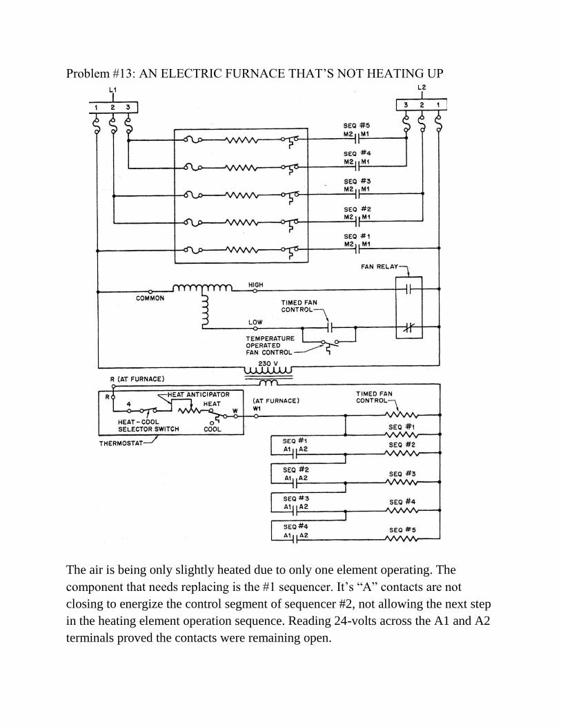
The air is being only slightly heated due to only one element operating. The
component that needs replacing is the #1 sequencer. It‟s “A” contacts are not
closing to energize the control segment of sequencer #2, not allowing the next step
in the heating element operation sequence. Reading 24-volts across the A1 and A2
terminals proved the contacts were remaining open.
Problem #14: A GAS FURNACE THAT‟S NOT HEATING
The next step is to focus on the main gas valve itself. Testing at SEC2 and TP7
and getting a 24-volt reading during an ignition attempt proved that the board was
allowing 24-volts out to the gas valve coil, proving that the switching assembly
inside the board was not the problem.
A follow up test with a voltmeter would show 24-volts applied to the gas valve coil
providing there was no problem with the wiring harness. With 24-volts applied to
the main gas valve coil, it should be opening and allowing gas flow to the burner.
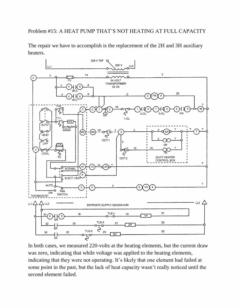
Problem #15: A HEAT PUMP THAT‟S NOT HEATING AT FULL CAPACITY
The repair we have to accomplish is the replacement of the 2H and 3H auxiliary
heaters.
In both cases, we measured 220-volts at the heating elements, but the current draw
was zero, indicating that while voltage was applied to the heating elements,
indicating that they were not operating. It‟s likely that one element had failed at
some point in the past, but the lack of heat capacity wasn‟t really noticed until the
second element failed.
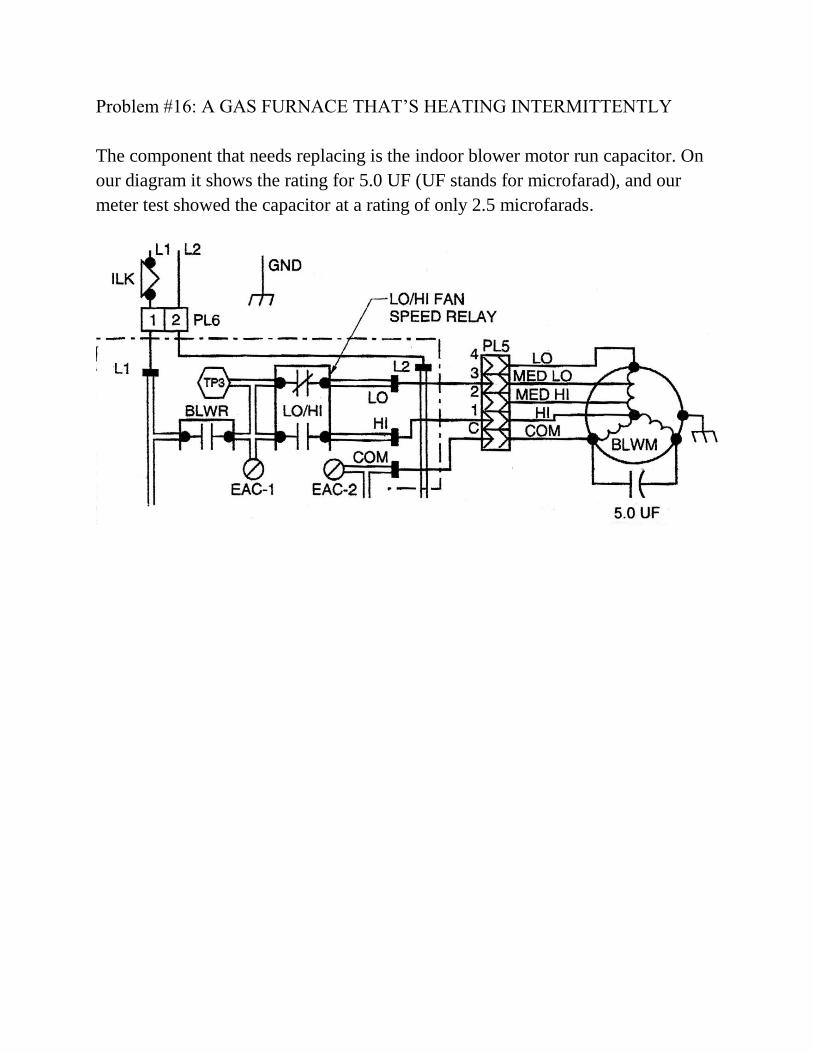
Problem #16: A GAS FURNACE THAT‟S HEATING INTERMITTENTLY
The component that needs replacing is the indoor blower motor run capacitor. On
our diagram it shows the rating for 5.0 UF (UF stands for microfarad), and our
meter test showed the capacitor at a rating of only 2.5 microfarads.
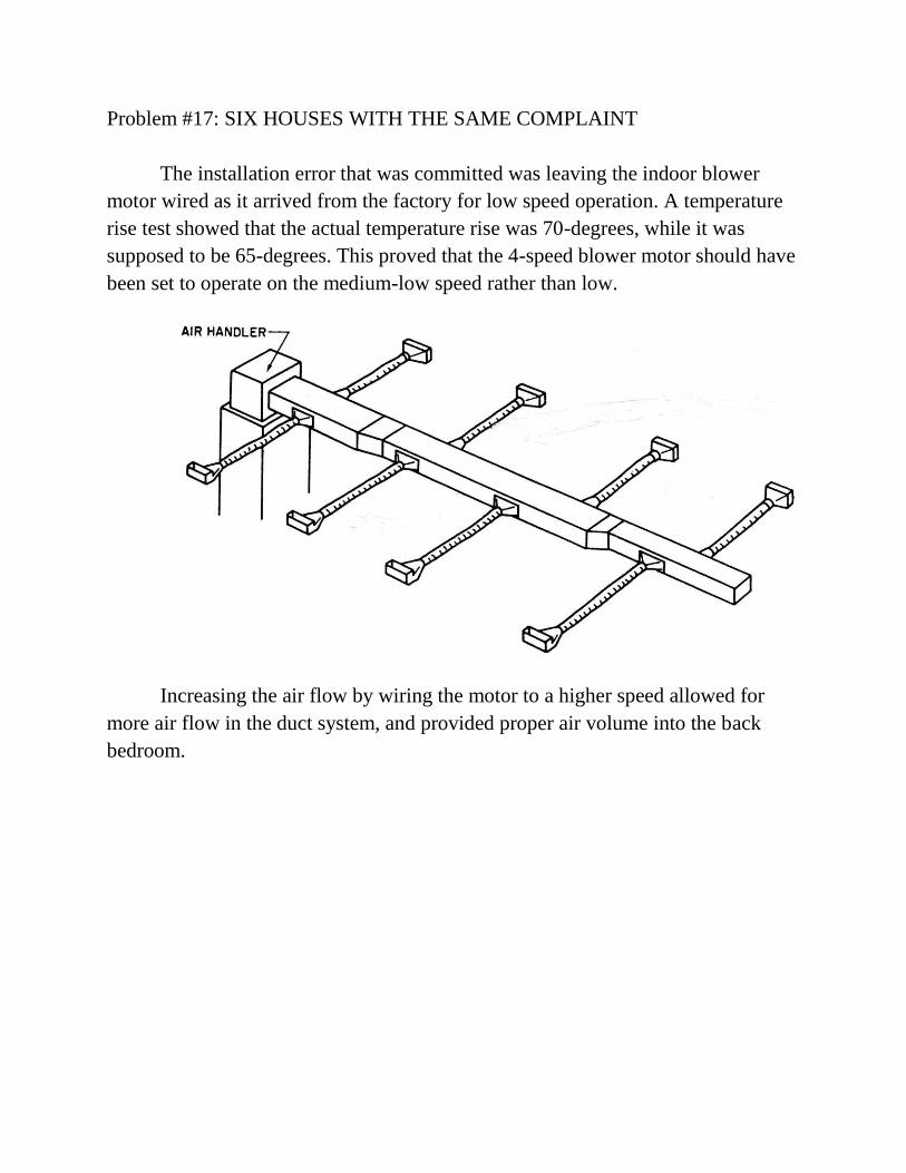
Problem #17: SIX HOUSES WITH THE SAME COMPLAINT
The installation error that was committed was leaving the indoor blower
motor wired as it arrived from the factory for low speed operation. A temperature
rise test showed that the actual temperature rise was 70-degrees, while it was
supposed to be 65-degrees. This proved that the 4-speed blower motor should have
been set to operate on the medium-low speed rather than low.
Increasing the air flow by wiring the motor to a higher speed allowed for
more air flow in the duct system, and provided proper air volume into the back
bedroom.
Problem #18
THE EXCESSIVELY EXPENSIVE HEAT PUMP
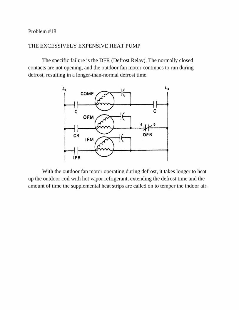
The specific failure is the DFR (Defrost Relay). The normally closed
contacts are not opening, and the outdoor fan motor continues to run during
defrost, resulting in a longer-than-normal defrost time.
With the outdoor fan motor operating during defrost, it takes longer to heat
up the outdoor coil with hot vapor refrigerant, extending the defrost time and the
amount of time the supplemental heat strips are called on to temper the indoor air.
Problem #19
A NEARLY ANCIENT PACKAGE UNIT THAT‟S NOT COOLING LIKE IT
SHOULD
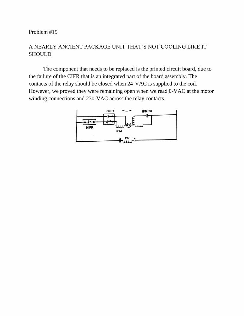
The component that needs to be replaced is the printed circuit board, due to
the failure of the CIFR that is an integrated part of the board assembly. The
contacts of the relay should be closed when 24-VAC is supplied to the coil.
However, we proved they were remaining open when we read 0-VAC at the motor
winding connections and 230-VAC across the relay contacts.
Problem #20
A SMALL WALK-IN FREEZER THAT‟S OPERATING ERRATICALLY
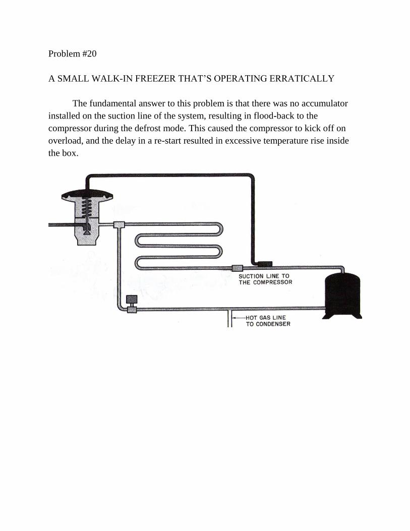
The fundamental answer to this problem is that there was no accumulator
installed on the suction line of the system, resulting in flood-back to the
compressor during the defrost mode. This caused the compressor to kick off on
overload, and the delay in a re-start resulted in excessive temperature rise inside
the box.