hustler 3500/3700 owner’s manual - · pdf file109627_0910 1-1 general information this...
TRANSCRIPT

109627_0910
Hustler 3500/3700Owner’s Manual
•••••P.O. Box 7000
•••Hesston, Kansas
•67062-2097

109627_0910
NOTICE OF REQUIREMENT OF SPARK ARRESTER MUFFLER
This equipment may create sparks that can start fires around dry vegetation. California Public Resources Code Sec-tion 4442.6 provides that it is unlawful to use or operate an internal combustion engine on any forest-covered, brush-covered, or grass-covered land unless the engine is equipped with a spark arrester maintained in effective working order. A spark arrester is a device constructed of nonflammable materials specifically for the purpose of removing and retaining carbon and other flammable particles over 0.0232 of an inch in size from the exhaust flow of an internal combustion engine that uses hydrocarbon fuels or which is qualified and rated by the United States For-est Service. Other states or federal areas may have similar laws. The Operator Should Contact Local Fire Agencies For Laws or Regulations Relating to Fire Prevention Requirements. THIS EQUIPMENT DOES NOT HAVE A SPARK ARRESTER AND YOU SHOULD CONTACT YOUR AUTHORIZED DEALER FOR THE PURCHASE OF A SPARK ARRESTER.
Inspect spark arrester daily; replace every 500 hours or as needed.
The Engine Owner’s Manual provides information regarding the U.S. Environmental Protection Agency (EPA) and the California Emission Control Regulation of emission systems, maintenance and warranty.
Keep Engine Owner’s Manual with your unit. Should the Engine Owner’s Manual become damaged or illegi-ble, replace immediately. Replacements may be ordered per the information found in the Product Informa-tion section of the owner’s manual.
The engine exhaust from this product contains chemicals known to the State
of California to cause cancer, birth defects or other reproductive harm.
WARNING:

109627_0910 1-1
GENERAL INFORMATIONThis manual applies to the following Hustler equipment
lines:
Hustler 3500Hustler 3700
To the new ownerThe purpose of this manual is to assist owners and operators
in maintaining and operating the 3500/3700 tractor. Please readit carefully; information and instructions furnished can help youachieve years of dependable performance.
A separate Engine Owner’s Manual is included with yourowner’s packet which contains additional engine informationthat will not be repeated in this manual. You are urged to read itbefore attempting any operation or repair of the engine.
The decals are designed to give the operator brief informationneeded in the daily operation and service of the machine. Thesedecals are not intended to be used in place of this manual butinstead are to be used as an extension of this manual. Thesedecals should not be removed or obliterated. Replace thesedecals if they become unreadable.
It is the owner’s responsibility to make certain that theoperators and mechanics read and understand this manual andall decals before operating this machine. It is also the owner’sresponsibility to make certain that the operators and mechanicsare qualified and physically able individuals, properly trained inthe operation of this equipment. All operator and mechanicsmust become familiar with the safe operation of the equipment,operator controls and safety signs.
Never let children or untrained people operate or service theequipment. Local regulations may restrict the age of theoperator.
For more detailed maintenance and adjustment informationrefer to the proper parts manual for your machine. Refer to theProduct Literature section of this manual for orderinginformation.
The owner/user can prevent and is responsible for accidents orinjuries occurring to themselves, other people or property.
Using this manualGeneral operation, adjustment and maintenance guidance is
outlined for both the experienced and novice Hustler user.Operating conditions vary considerably and cannot all beaddressed individually. Through experience, however,operators should find no difficulty in developing good operatingskills suitable to most conditions.
Directions used in this manual, for example RIGHT or LEFT,refer to directions when seated on tractor facing forward, unlessotherwise stated.
Photographs and illustrations used were current at the time of
printing, but subsequent production changes may cause yourmachine to vary slightly in detail. Hustler Turf Equipmentreserves the right to redesign and change the machine as deemednecessary, without notification and without incurring anyobligation to make changes or additions to equipment soldpreviously. If a change has been made to your machine which isnot reflected in this owner’s manual, or the parts manual, seeyour Hustler dealer for current information and parts.
Warranty registrationThe Delivery and Warranty Registration form must be
completed and signed to validate your warranty protection. Asthe new equipment owner, you are expected to see that the formis completed and forwarded to Hustler Turf Equipment at timeof delivery.
Be sure to register the tractor plus each attachment thatdisplays a model and serial identification number plate withHustler Turf Equipment.
IMPORTANT: Any unauthorized modification, alteration,or use of non-approved attachments voids the warranty andreleases Hustler Turf Equipment from any liability arising fromsubsequent use of this equipment.
Tractor gross vehicle weight (GVW)This tractor has a maximum gross vehicle weight (GVW) of
3500 lbs. which must not be exceeded. Use only Hustlerapproved attachments and accessories
Model and serial numberTractor model and serial numbers are found on the serial
identification plate, located on the frame directly in front of theleft rear wheel.
These numbers are required on the Warranty Registrationform. They will also assure you of the correct service partswhen replacement becomes necessary.
Parts and serviceUse original Hustler replacement parts only. These parts are
available through your local Hustler dealer. To obtain prompt,efficient service, always provide the following informationwhen ordering parts:
1. Correct part description2. Correct part number3. Correct model number.4. Correct serial number.All warranty repair and service must be handled through an
authorized Hustler dealer. Arrangements should be madethrough your local service center.

1-2 109627_0910

109627_0910 1-3
3500/3700 TRACTORSHUSTLER TURF COMMERCIAL PRODUCT
TWO YEAR (1500 HOURS) LIMITED WARRANTY
WHAT IS COVERED BY THIS WARRANTYHustler Turf Equipment, makes the following warranty to the original pur-
chaser only:a. Hustler Turf Equipment Tractors and Power Units are warranted for two
(2) years or 1500 hours whichever comes first, from date of deliveryon all defects in materials and workmanship.
If the Purchaser discovers within this warranty period a defect in materialsor workmanship:
� He must promptly notify Hustler Turf Equipment, or an authorizeddealer, in writing of the defect. In no event shall such notification bereceived by Hustler Turf Equipment, or an authorized dealer later than30 days after expiration of warranty.
� Within a reasonable time after such notification, Hustler Turf Equip-ment, will correct any defect in material or workmanship on the Hus-tler Turf Equipment, by repairing or replacing part(s) with either newor used replacement parts.
� Such repair, including parts and labor shall be at the expense of HustlerTurf Equipment, and,
b. Rental Units (90 days): Within 90 days of date of delivery Hustler TurfEquipment, provides a limited warranty on all materials and workman-ship for units used for rental purposes. � If the Purchaser discovers within this warranty period a defect in mate-
rials or workmanship:� He must promptly notify Hustler Turf Equipment, or an authorized
dealer, in writing of the defect. In no event shall such notification bereceived by Hustler Turf Equipment, or an authorized dealer later than120 days from date of delivery.
� Within a reasonable time after such notification, Hustler Turf Equip-ment, will correct any defect in material or workmanship on the Hus-tler Turf Equipment, by repairing or replacing part(s) with either newor used replacement parts.
� Such repair, including parts and labor shall be at the expense of HustlerTurf Equipment, and,
c. The Shibaura diesel engine is covered by a three (3) year or 2000 hour,whichever comes first, limited warranty, to the original owner only, and,
d. The battery is covered by a one (1) year limited warranty to the originalowner only.
WHO MUST PERFORM THE WARRANTY SERVICEAll warranty service will be performed by dealers authorized by Hustler
Turf Equipment. Service calls and/or transportation expense of the productto and from the authorized dealer, for warranty work, will be paid by the ownerof the product. For warranty service contact an authorized dealer.
WHAT IS NOT COVERED BY THIS WARRANTYHustler Turf Equipment, does not warranty: � Some product, components or parts not manufactured by Hustler Turf
Equipment� Repairs made by unauthorized persons� Damage caused by use of the Hustler Turf Equipment for purposes
other than those for which it was designed� Damages caused by disasters such as fire, flood, wind, and lightening� Damages caused by neglect, abuse, abnormal use, improper or unrea-
sonable use, accident, negligence, misuse or foam filled/solid filledtires
� Repairs or replacement resulting from the use of unauthorized parts,accessories or attachments
� Repairs or replacement as the result if any alterations or modifications,in the determination of Hustler Turf Equipment, which adverselyaffects the operation, performance or durability of the equipment.
� Hustler Turf Equipment which has the serial number removed or madeillegible
� Depreciation or damage caused by normal wear, lack of reasonable andproper maintenance, failure to follow the product’s owner’s manual
operating, maintenance and adjustment instructions or other opera-tional instructions provided by Hustler Turf Equipment.
� Normal maintenance parts and service including, but not limited to, fil-ters, fuel, lubricants, tune-up parts, belts, blades, blade sharpening,bearings, brake or steering adjustments
� Repairs necessary due to improper fuel, contaminates in the fuel sys-tem, or failure to properly prepare the fuel system prior to any periodof non-use over three months
� Damage caused by foam filled or solid filled tires.
DISCLAIMER OF WARRANTYThe foregoing warranties are in lieu of all other warranties, expressed or
implied, including but not limited to the implied warranties of merchantabilityand fitness for a particular purpose. However, if the Hustler Turf Equipment ispurchased as a consumer product, any implied warranty of merchantability orfitness for a particular purpose is limited to the duration of this limited warranty.Some states do not allow limitations on how long an implied warranty lasts, sothe above limitation may not apply to you. This warranty gives you specificlegal rights, and you may also have other rights which vary from state to state
LIMITATION OF REMEDIESIn no case shall Hustler Turf Equipment, be liable for any special, inciden-
tal, or consequential damages based upon breach of warranty, breach of contract,negligence, strict liability in tort, or any other legal theory.
Such damages include, but are not limited to:� Loss of profits� Loss of savings or revenue� Loss of use of Hustler Turf Equipment or any associated equipment� Cost of capital� Cost of any substitute equipment, facilities, services or downtime� The claims of third parties including customers, and injury to property
Some states do not allow the exclusion or limitation of incidental or conse-quential damages, so the above limitation or exclusion may not apply to you.
TIME LIMITAny action for breach of warranty must be commenced within 30 days after
expiration of warranty in a non-rental application. Any action for breach ofwarranty must be commenced within 30 days after expiration of warranty in arental application.
NO OTHER WARRANTIESUnless modified in writing, signed by both parties, and approved by the
President of Hustler Turf Equipment, this agreement is understood to be thecomplete and exclusive agreement between the parties, superseding all prioragreements, oral or written, and all other communications between the partiesrelating to the subject matter of this agreement. No employee of Hustler TurfEquipment, or any other party is authorized to make any warranty in addition tothose made in this agreement.
ALLOCATION OF RISKSThis agreement allocates the risks of product failure between Hustler Turf
Equipment, and the purchaser. This allocation is recognized by both parties andis reflected in the price of the goods.
OWNER'S RESPONSIBILITYYou must maintain your Hustler Turf Commerical Product following the
maintenance procedures described in your owner's manual. Such routine main-tenance, whether performed by a dealer or by you, is at your expense.
This machine like any other powered equipment is potentially danger-ous unless properly operated. Any operator must be cautious and keep safetyin mind at all times. Any operator, prior to using the Hustler Turf Equipment,should thoroughly familiarize himself with the owner's manual regarding opera-tion and safety of the machine, as well as all safety warnings on the machineitself.

1-4 109627_0910
WARRANTY REGISTRATION1. Dealers must register the unit on-line at www.Hustlerdealer.com or by fill-
ing out the Warranty registration form, provided in the owner’s packet. Ifusing the Warranty registration form it MUST be completed and signed bythe authorized dealer and original purchaser.
2. For validation, the completed Warranty registration form MUST be for-warded to Hustler Turf Equipment, within ten (10) days following date ofpurchase.
3. The date of purchase constitutes delivery.

109627_0910 2-1
SAFETY PRECAUTIONSThis safety alert symbol is used to call attention to a
message intended to provide a reasonable degree ofPERSONAL SAFETY for operators and other personsduring the normal operation and servicing of thisequipment.
DANGER: denotes immediate hazards which WILLresult in severe personal injury or death.
WARNING: denotes a hazard or unsafe practice whichCOULD result in severe personal injury or death.
This manual uses two other words to highlight information.IMPORTANT calls attention to special mechanicalinformation and NOTE emphasizes general informationworthy of special attention.
All operators and mechanics should read this manual,and be instructed about safe operating and maintenanceprocedures. If the operators or mechanics cannot readand understand English, it is the owner’s responsibility toexplain this material to them.
Improper use or maintenance of this machine by theoperator or owner can result in injury. To reduce thepotential for injury, comply with these safety instructionsand always pay attention to the safety alert � symbol,which means DANGER or WARNING - “personal safetyinstructions.” Failure to comply with the instructions mayresult in personal injury or death.
Incorrect usage of this machine may result in severeinjury. Personnel operating and maintaining it should betrained in the proper use and should read the manualscompletely and thoroughly before attempting to set-up,operate, adjust, or service this machine.
The decals are designed to give the operator briefinformation needed in the daily operation and service of themachine. These decals are not intended to be used in place ofthis manual but instead are to be used as an extension of thismanual. These decals should not be removed or obliterated.Replace these decals if they become unreadable.
• It is the owner’s responsibility to make certain that the operators and mechanics read and understand this man-ual and all decals before operating this machine.
• It is also the owner’s responsibility to make certain that the operators and mechanics are qualified and physically able individuals, properly trained in the operation of this equipment.
• All operators and mechanics must become familiar with the safe operation of the equipment, operator controls and safety signs.
• Never let children or untrained people operate or service the equipment. Local regulations may restrict the age of the operator.
• The owner/user can prevent and is responsible for acci-dents or injuries occurring to themselves, other people or property.
• The owner should also ensure that the operator/mechanic know that they are responsible for their own safety as well as the safety of other persons within the vicinity. Remember, the operator is responsible for accidents or hazards occurring to other people or their property.
Safety and Instruction Decals
�Specific safety warning decals are located on the equipment near the immediate areas of potential hazards. These decalsshould not be removed or obliterated. Replace them if they become non-readable.
The following illustrations show the various decals that are located on the machine. A brief explanation, for those requiringone, is shown to help the operator understand the meanings of these decals.
• Read Owner’s Manual and decals before attempting to operate this machine. 728469 REV. B
USE ONLY LOWOR ULTRA LOWSULFUR FUEL
• Do not smoke while refueling.• Do not fill tank with engine running, or
while the engine is hot.• Allow engine to cool before storing
machine inside a building.• Store away from open flame or spark.• Clean up any gasoline spills.• Do not refuel while in enclosed trailer or
other enclosed areas

2-2 109627_0910
WARNING: Hot surface! • Keep a safe distance from the machine. • Do not open while engine is hot. Wait
until the system has fully cooled to ser-vice.
• Always keep shields or covers in place
WARNING: Hot fluid under pressure
• Keep hands, feet and clothing clear of this area.
• Always keep shields or covers in place while machine is in operation.
WARNING: Rotating fan blade!
601968
• Avoid hydraulic fluid escaping under pressure
• Hydraulic fluid escaping under pressure can penetrate skin.
• Hydraulic fluid escaping under pressure may have sufficient force to penetrate skin and cause serious injury. Foreign fluid injected into the skin must be surgi-cally removed within a few hours by a doctor, familiar with this form of injury, or gangrene may result.
• Before applying pressure to hydraulic system, make sure all connections are tight and all hoses and lines are in good condition.
• Relieve all pressure in the system before disconnecting or working on hydraulic lines.
• To find a leak under pressure, use a piece of cardboard or wood – never use your hands.
• To relieve all pressure in system, lower attachment and turn engine off.
WARNING: Fluid under pressure!
DANGER: Battery Hazards
• Always wear eye protection when checking the battery, acid can cause serious injury to skin and eyes. If contact occurs, flush area with clean water and call physician imme-diately. Acid will also damage clothing.
• Hydrogen gas forms inside the battery. This gas is both toxic and flammable and may cause an explosion if exposed to flame. Always remove the negative ground first and replace it last.
• Do not allow open flame near the battery when charging.
• Avoid skin contact with battery acid.
109627_0910 2-3
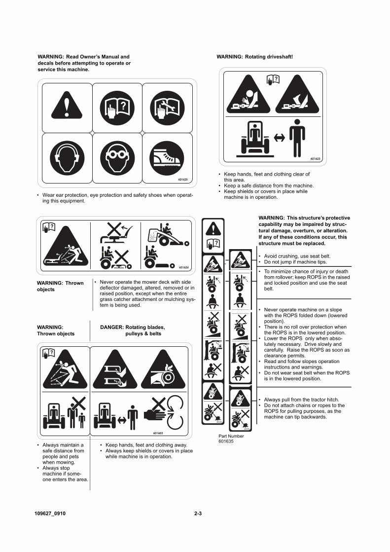
WARNING: Read Owner’s Manual and decals before attempting to operate or service this machine.
• Wear ear protection, eye protection and safety shoes when operat-ing this equipment.
601623
• Keep hands, feet and clothing clear of this area.
• Keep a safe distance from the machine.• Keep shields or covers in place while
machine is in operation.
WARNING: Rotating driveshaft!
601624
• Never operate the mower deck with side deflector damaged, altered, removed or in raised position, except when the entire grass catcher attachment or mulching sys-tem is being used.
WARNING: Thrown objects
WARNING: This structure’s protective capability may be impaired by struc-tural damage, overturn, or alteration. If any of these conditions occur, this structure must be replaced.
• Avoid crushing, use seat belt.• Do not jump if machine tips.
• To minimize chance of injury or death from rollover; keep ROPS in the raised and locked position and use the seat belt.
• Never operate machine on a slope with the ROPS folded down (lowered position).
• There is no roll over protection when the ROPS is in the lowered position.
• Lower the ROPS only when abso-lutely necessary. Drive slowly and carefully. Raise the ROPS as soon as clearance permits.
• Read and follow slopes operation instructions and warnings.
• Do not wear seat belt when the ROPS is in the lowered position.
• Always pull from the tractor hitch. • Do not attach chains or ropes to the
ROPS for pulling purposes, as the machine can tip backwards.
601635
601635
Part Number 601635
DANGER: Rotating blades, pulleys & belts
WARNING: Thrown objects
• Keep hands, feet and clothing away.• Always keep shields or covers in place
while machine is in operation.
• Always maintain a safe distance from people and pets when mowing.
• Always stop machine if some-one enters the area.

2-4 109627_0910
601415601415
WARNING: Rollover!
• Mow a safe distance (minimum of 10 feet) away from drop-offs, retaining walls, drainage ditches, embankments, water, and other types of hazards to avoid a wheel dropping over the edge or to avoid the ground from breaking away.
WARNING: Back over!
• Always be aware of what is behind the machine before backing up. Do not mow in reverse unless absolutely neces-sary. Always look down and behind before and while backing up.
• Do not carry passengers• Always stop machine if someone enters
the area.
WARNING: Rollover!
• Do not operate on slopes greater than 15 degrees.
• Keep all movement on slopes slow and gradual. Never make sudden changes in speed and direction.
WARNING: Ejection!
• Never push down suddenly on reverse or brake pedal while the machine is in forward motion because machine may tip forward causing loss of control.
• Slow down before turning.• Wear seat belt
601415
WARNING: Ejection!
• Never drive the tractor at high speeds without a front-end attachment mounted to the tool bars.
• Never push down suddenly on reverse or brake pedal while the machine is in forward motion because machine may tip forward causing loss of control.
WARNING: Ejection!
• Never push down suddenly on reverse or brake pedal while the machine is in forward motion because machine may tip forward causing loss of control.
• Keep all movement on slopes slow and gradual.
• Do not make sudden changes in speed or direction.
• Keep attachment as low to the ground as possible, mower decks should rest on the gauge wheels.
• Keep deck gauge wheels on the ground during transport.
WARNING: Loss of traction
• While driving on slopes, always run in AWD (All wheel drive) locked position.
• Keep all movement on slopes slow and gradual.
• Never make sudden changes in speed or direction.

109627_0910 2-5
INTERNATIONAL SYMBOLS
As a guide to the operation of your tractor, various international symbols have been used on instruments and controls. Thesesymbols are depicted and described below.
Hours Recorded
Engine Water Temperature
Increase
Decrease
Fuel Level
High Range
Low Range
Auto AWD
Full Time AWD
Engine Oil Pressure
Air Filter
Continously Variable
Neutral
Diesel Fuel
Lock
Release Lock
Differential Lock
Volume Empty
Engine Start
Engine Oil
Engine Stop
Glow
Parking Brake
Battery
Power Take-off (ON)
Attachment (Lowered)
Remote Cylinder (Retracted)
Remote Cylinder (Extended)
Volume Full
Control Lever Hold
Fast
Slow
Power Take-off (OFF)
Attachment (Raised)

2-6 109627_0910

109627_0910 2-7
SLOPE GUIDE.
1. Hold this sheet of paper in front of you. Make sure that Line A is horizontal.2. Align Line B with a vertical surface such as pole, tree or building.3. Fold the paper along the slope guide lines (C, D or E).4. Align the closest slope guide line with the ground slope. This will give you a close estimation of the ground slope to be
mowed.
Slope Guide Lines
Line
B
D (10o)
C (5o)
E (15o)
Line A
Use this diagram when determining the degree of slope to be mowed

2-8 109627_0910

109627_0910 3-1
OPERATIONSafe Operating Practices
This product is capable of amputating hands and feet andthrowing objects. Always follow all safety instructions toavoid serious injury or death.
Operation� Evaluate the terrain to determine what accessories and
attachments are needed to properly and safely performthe job. Only use accessories and attachmentsapproved by the manufacturer.
� Never leave a running machine unattended. Park themachine on level ground. Place park brake lever in thebrake engaged position, place the PTO lever in the“OFF” position, lower attachment, remove ignitionswitch key before leaving operator’s seat for any rea-son including unclogging the chute.
� Do not change the engine governor setting or over-speed the engine.
� Always remain seated while operating machine.� Always keep safety shields and covers in place, except
for servicing.� Always maintain a safe distance from people and pets
when mowing. Always stop machine if someoneenters the area.
� Always operate machine in daylight or with adequateworking lights.
� Follow daily and weekly checklists, making sure hosesare tightly secured and bolts are tightened.
� Always observe traffic laws while driving machinefrom one location to another. Watch for traffic whenoperating near or crossing roadways.
� Always be alert for hazards such as rocks, metalobjects and other debris which may be thrown orentangled by mower blades. Watch out for holes ordeep depressions.
� Inspect area to be mowed for hazards such as rocks,metal objects and other debris which may be thrown orentangled by mower blades. Remove these objectsbefore mowing.
� Always inspect machine for damage after striking aforeign object. If damage is found, repair machineimmediately. Be sure to stop on level ground, placepark brake lever in the brake engaged position, placethe PTO lever in the “OFF” position, lower attachment,remove ignition switch key before leaving operator’sseat to inspect damage.
� Never engage the PTO Control Lever unless the PTOshaft is securely connected to a power driven attach-ment.
� Always wear adequate ear protection, such as earplugs,when operating this equipment as prolonged exposureto uncomfortable or loud noises can cause impairmentor loss of hearing. Do not wear radios or music head-phones while operating the machinery. Safe operationrequires your full attention.
� Do not operate the equipment while wearing sandals,tennis shoes, sneakers, shorts or any type of loose fit-ting clothing. Long hair, loose clothing or jewelry may
get tangled in moving parts. Always wear long pants,safety glasses, ear protection and safety shoes whenoperating this machine.
� Always be aware of what is behind the machine beforebacking up. Do not mow in reverse unless absolutelynecessary. Always look down and behind before andwhile backing up.
� Never push down suddenly on brake pedal while themachine is in forward motion because machine may tipforward causing loss of control.
� Never push down suddenly on the HST reverse pedalwhile the machine is in forward motion becausemachine may tip forward causing loss of control.
� Never drive the tractor at high speeds without a front-end attachment mounted to the tool bars. Keep theattachment as low to the ground as possible, mowerdecks should rest on the gauge wheels.
� Never operate a poorly maintained machine.� Never attempt high speed maneuvering, especially in
crowded or congested areas.� Never allow persons to operate this machine without
proper instruction or allow children to operatemachine. Allow only responsible adults who are famil-iar with these instructions to operate this machine.
� Never put hands or feet under any part of the machinewhile it is running.
� Never carry passengers.� Never direct discharged material toward anyone.
Avoid discharging material against a wall or obstruc-tion. Material may ricochet back toward the operator.Always disengage the blades and wait for them to stopbefore crossing gravel drives, walks or roads.
� Always keep clear of the mower blades and attach-ments during their operation.
� Turn off blades when not mowing.� Slow down before turning.� Stop the engine before removing the grass catcher or
unclogging the discharge chute. Never clear the dis-charge chute with the engine running. Turn off theengine and be sure the blades have stopped beforecleaning. Use a stick to clear a plugged discharge area.Never use your hand!
� Do not operate the machine while under the influenceof alcohol or drugs.
� Exercise caution when loading or unloading themachine onto a trailer or truck.
� Always wear safety goggles or safety glasses with sideshields when operating the tractor.
� Data indicates that operators, age 60 years and above,are involved in a large percentage of riding mower-related injuries. These operators should evaluate theirability to operate the mower safely enough to protectthemselves and others from serious injury.
� Follow the manufacturer’s recommendation for wheelweights or rear counter-balance weights.
� If any attachment or additional weight is mounted onthe front of the unit, any rapid movement of the HST
3-2 109627_0910
pedals in either direction could result in a reaction ofthe tractor that can cause serious injury.
� When desconnection on attachment that uses the trac-tor PTO output shaft to power the attachment, the pow-ered shaft of device must also be disconnected from thetractor PTO output shaft. Never leave an unsupportedPTO device attached to the tractor PTO output shaft, ifit is not completely and properly assembled to theattachment on which it’s use is intended.
� Clean flammable material from machine. Preventfires by keeping engine compartment, exhaust area,battery, fuel line, fuel tank and operator’s stationclean of accumulated trash, grass clippings, andother debris. Always clean up spilled fuel and oil.
Using a ramp� Use extreme caution when loading and unloading a
unit onto a truck or trailer with a ramp.� Use only a single, full width ramp; do not use individ-
ual ramps for each side of the unit. Having a full widthramp provides a surface for the tractor frame to contactif the unit starts to tip backwards. It also reduces therisk of a wheel going off and the machine tipping over.
� Do not exceed a 15 degree angle between the ramp andthe ground or between the ramp and the trailer or truck.
� When on a ramp avoid sudden acceleration.
Slope OperationSlopes are a major factor in loss-of-control and tip-over
accidents, which can result in severe injury or death. Allslopes require extra caution. REMINDER: Only operateon slopes of 15 degrees or less.
� Use extreme caution when operating on slopes.• Be extremely careful changing directions on a slope.
Slow down.• Do not operate where the machine could slip or tip.• Turn slowly• Turn on the most level part of the slope• While driving on slopes, always run in AWD (All
wheel drive) locked position. • Never make sudden changes in speed or direction.• If it becomes necessary to turn downhill, turn slowly
and gradually, if possible.� Watch for holes, ruts, bumps, rocks or other hidden
objects. Uneven terrain could overturn the machine.Tall grass can hide obstacles.
� Remove obstacles such as rocks, tree limbs, etc.� Keep all movement on slopes slow and gradual. Do
not make sudden changes in speed or direction.� Avoid starting and stopping on a slope. If tires lose
traction, disengage the blades and proceed slowlystraight down the slope.
� Mow a safe distance (minimum of 10 feet) away fromdrop-offs, retaining walls, drainage ditches, embank-ments, water, and other types of hazards to avoid awheel dropping over the edge or to avoid the groundfrom breaking away. This will reduce the risk of themachine suddenly rolling over causing serious injuryor death.
� Use a walk behind, push mower or hand-held trimmeron slopes and near drop-offs, retaining walls, drainageditches, embankments and water to avoid machine roll-over and serious injury or death.
� Do not mow on wet grass. Reduced traction couldcause sliding and loss of steering control.
� If the mower’s tires lose traction when operating onslopes, disengage the blades, engage the park brake,turn the engine off and get help.
� Never make sudden starts, stops, turns, or reversedirection, especially when maneuvering on slopes.The steering is designed for sensitive response. Rapidmovement of the steering wheel or HST foot pedals ineither direction could result in a reaction of the tractorthat can cause serious injury.
� Never stop suddenly while going down slopes. Thisaction may result in a reaction of the tractor that cancause serious physical injury.
� The Hustler mower is capable of operating horizontally(traverse) on moderately steep slopes. When operatingon slopes up to 15 degrees, be aware of any conditionsthat may cause the tractor drive tires to lose tractionresulting in a possible loss of control of the machine.An operator should not operate on a slope until he isthoroughly familiar with the equipment.Do not operate on slopes greater than 15 degrees.Refer to Slope Guide, page 2-7, when determining thedegree of slope to be mowed.It is strongly recommended that the operator drive themachine off of the slope, using extreme caution, if anysign of loss of traction is detected. Wait until the con-dition that caused the problem is resolved beforeattempting to operate on the slope again.Terrain conditions can affect traction resulting in possi-ble loss of control of the machine. Some of the condi-tions to be aware of are:1. Wet terrain2. Depressions in the ground; i.e. holes, ruts, washouts3. Mounds of dirt4. Soil type; i.e. sand, loose dirt, gravel, clay5. Grass type, density, and height6. Extremely dry conditions of grass7. Tire pressureThe attachments mounted to the tractor will also affectthe way it handles on a slope. Be aware that eachattachment’s characteristics vary.Do not tow on slopes. The weight of the towed equip-ment may cause loss of traction and loss of steeringcontrol.Another consideration to safe mowing on slopes is tobe aware of what is located at the bottom of the slope.Extreme caution should be used when there is a hazardlocated at the bottom of the slope. Some examples are:1. Water; i.e. lake, river2. Cliffs, retaining walls3. Roads, highways4. Buildings5. RocksThese are just a few examples of situations when cau-tion must be used when operating on a slope. There are

109627_0910 3-3
many other possibilities too numerous to mention.Just remember to always exercise extreme cautionwhen operating on any slope.
� The ROPS will minimize chance of injury or deathfrom rollover. Seat belt must be fastened while oper-ating a machine equipped with ROPS in the raisedand secured position. Both retaining pins and hairpins must be installed. Failure to use seat belt willresult in serious injury in the event of a roll over.
ChildrenTragic accidents can occur if the operator is not alert to
the presence of children. Children are often attracted tothe machine and the mowing activity. Never assume thatchildren will remain where you last saw them.
� Never leave machine unattended with ignition key inswitch, especially with children present.
� Children or bystanders may be injured if they move orattempt to operate the tractor while it is unattended.Always disengage PTO lever, engage park brake, stoptractor engine, and remove ignition key when leavingoperator’s seat.
� Keep children out of the mowing area and under thewatchful care of a responsible adult other than theoperator.
� Be alert and turn the machine off if children enter thearea.
� Before and while backing, look behind and down forsmall children.
� Never carry children, even with the blades off. Theymay fall off and be seriously injured or interfere withsafe machine operation. Children who have beengiven rides in the past may suddenly appear in themowing area for another ride and be run over orbacked over by the machine.
� Never allow children to operate the machine.� Use care when approaching blind corners, shrubs,
trees, the end of a fence or other objects that mayobscure vision.
� Never allow children or others in or on towed equip-ment.
Instrument PanelA. Electronic hour meter (Figure 3-1) — Registers 1/10
hour increments up to 9,999.9 total hours. Connectedto the ignition switch, the meter records theaccumulative time while the ignition key is switchedto the RUN position.
B. Temperature gauge and alarm (Figure 3-1) —When the needle is in the middle area, the engine is atits normal operating temperature. When the needlereaches the “H” side of the gauge it indicates theengine coolant has reached an unsafe temperature. Ifthis occurs, shut down the machine as soon aspossible. Never risk continued operation; hightemperatures can severely damage the engine. The coolant temperature fluctuates depending onambient temperatures and working loads. If the needleis at the “H” side during operation, the overheat alarmbuzzer sounds.
C. Fuel gauge (Figure 3-1) — This gauge indicates theamount of fuel in the tank.
D. Glo-plug warning light (Figure 3-1) — Comes onwhen turning the key switch to the “HEAT” positionor “START” position. This light will stay on forapproximately 5 seconds in the “HEAT” Position.
E. Oil pressure warning light and alarm (Figure 3-1)— This light comes on when the ignition switch isplaced in the “RUN” position and stays lit until theengine is running and a safe oil pressure is developed.If light comes on during operation, shut engine offimmediately and locate and correct the problem.When oil pressure falls below 4.25 psi (29.4 kPa), thealarm buzzer will sound. IMPORTANT: The operatormust occasionally check the crankcase for proper oillevel.NOTE: The alarm buzzer will sound when enginestops with key left inserted at “RUN” position. Inorder to stop the alarm buzzer, return the key to“STOP” position.
F. Charge indicator warning light (Figure 3-1) — Thislight comes on when the ignition switch is placed inthe “RUN” position and stays lit until the engine isrunning. If it remains lit the charging system is notoperating normally. Investigate the cause as soon aspossible, otherwise the battery will fully discharge.
G. Air cleaner restriction warning light (Figure 3-1)— When the air cleaner element is clogged by foreignsubstances, such as dust, and clean air is restricted tothe engine, this light will illuminate. Refer to theEngine Air Filter section of this manual for detailedinformation.
H. Parking brake warning light (Figure 3-1) — Whenthe parking brake is applied, this light will illuminate.
SwitchesA. Ignition switch (Figure 3-2) — A four position
switch: off, run, pre-heat and start. With key inserted,rotate it clockwise to “PRE-HEAT” position and the“START” position; release key when engine starts, andswitch will automatically return to the “RUN”position.Turning the key to the “RUN” position activates thewarning lights and instruments.
Figure 3-1
A B C
DEG
H
F

3-4 109627_0910
B. Head light switch (Figure 3-3) — This switch islocated under the instrument panel. Push the switch inand rotate the ignition key to the “RUN” position toturn on the head lights.
ControlsA. Throttle control (Figure 3-4 — A cable is linked to
engine throttle for controlling engine speed. Movelever forward to increase engine rpm, move leverrearward to decrease engine rpm. NOTE: Alwaysoperate the mower deck or attachment at full engineRPM.
B. Master brake pedal (Figure 3-5) — Depress themaster brake pedal to stop the unit.NOTE: The cruise control switch will be returned tothe “OFF” position by depressing the master brakepedal, if the cruise control switch is in the “SET” posi-tion.
C. Park brake (Figure 3-6) — The park brake should beapplied whenever the tractor is parked or when theoperator is out of the seat. To set the park brake, pullup on the park brake lever. To release the park brake,press on the brake lever release button while pushingdown on the park brake lever.
WARNING: Do not park on a slope. If necessary topark on a slope fully engage the park brake and besure to block or chock the wheels to prevent acci-dental rolling of the machine.
D. Differential lock pedal (Figure 3-7) — Depressingthe pedal, locks the front axle shafts together,providing additional traction in wet or loose soil.
WARNING: The tractor is very difficult to steerwith the differential lock applied.
E. Hydrostatic transmission (HST) foot pedals (Figure3-5) — The ground speed of the unit is continuously
Figure 3-2
Figure 3-3
Ignition switch
Pre-heat
Start
Run
Off
A
Head light switchB
Figure 3-4
Figure 3-5
ThrottleA
Master brake pedal
HST foot pedals
Forward travel pedal
Reverse travel pedal
B
E

109627_0910 3-5
variable from zero to full rated speed in each range.The ground speed is controlled by these pedals.Depress the forward travel pedal to progressivelyincrease forward speed. For reverse travel, depress thereverse travel pedal. NOTE: These pedals must be inneutral (not depressed) to start the engine.
F. Cruise control switch (Figure 3-8) — Used tomaintain a constant forward speed. After attaining thedesired speed with the forward travel pedal, put theswitch to the “ON “position, and the unit will maintainthe set speed when the pedal is released.To cancel the speed setting or stop the unit, put thecruise control switch to the “OFF” position or firmlydepress the master brake pedal.
WARNING: To avoid injury, the cruise controlswitch should not be put in the “ON” positionwhen operating at transport speed or when inreverse.
G. Transmission Selector lever (Figure 3-9 & Figure 3-10) — The Range Selection and the All Wheel Drive(AWD) Selection are controlled by the TransmissionSelector lever. This lever can only be shifted when theHST foot pedal is in the Neutral positionWhen the Transmission Selector lever is located in theinside slot, the tractor will run in Automatic AWDmode. When the lever is in this position there arethree settings: High range (H), Low range (L) andNeutral.
Figure 3-6
Figure 3-7
Park brake lever
Release button
C
Differential lock pedalD
Figure 3-8
Figure 3-9
Figure 3-10
F
Transmission selector lever shown in the Automatic AWD position
G
Transmission selector lever shown in the locked AWD position
High range Low range
G
3-6 109627_0910
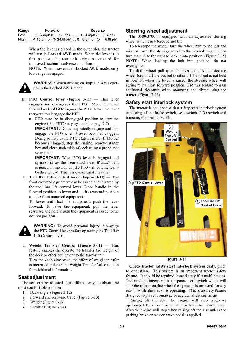
Range Forward ReverseLow . . . . 0 - 6 mph (0 - 9.7kph) . . . . 0 - 4 mph (0 - 6.3kph)High . . . 0-15.2 mph (0-24.5kph) . . 0 - 9.9 mph (0 - 15.8kph)
When the lever is placed in the outer slot, the tractorwill run in Locked AWD mode. When the lever is inthis position, the rear axle drive is activated forimproved traction in adverse conditions.NOTE: When mower is in Locked AWD mode, onlylow range is engaged.
WARNING: When driving on slopes, always oper-ate in the Locked AWD mode.
H. PTO Control lever (Figure 3-11) — This leverengages and disengages the PTO. Move the leverforward and hold it to engage the PTO. Move the leverrearward to disengage the PTO.a. PTO must be in disengaged position to start the
engine ( See “PTO stop system:” on page3-7).IMPORTANT: Do not repeatedly engage and dis-engage the PTO when Mower becomes clogged.Doing so may cause PTO clutch failure. If Mowerbecomes clogged, stop the engine, remove starterkey and clean underside of deck using a probe, notyour hand.IMPORTANT: When PTO lever is engaged andoperator raises the front attachment, if attachmentis raised all the way up, the PTO will automaticallybe disengaged. This is a tractor safety feature!
I. Tool Bar Lift Control lever (Figure 3-11) — Thefront mounted equipment can be raised and lowered bythe tool bar lift control lever. Place handle in theforward position to lower and to the rearward positionto raise front mounted equipment.To lower and float the equipment, push the leverforward. To raise the equipment, pull the leverrearward and hold it until the equipment is raised to thedesired position.
WARNING: To avoid personal injury, disengagethe PTO Control lever before operating the Tool BarLift Control lever.
J. Weight Transfer Control (Figure 3-11) — Thisfeature enables the operator to transfer the weight ofthe deck or other equipment to the tractor unit.Turn the knob clockwise, the effort of weight transferis increased, refer to the Weight Transfer Valve sectionfor additional information.
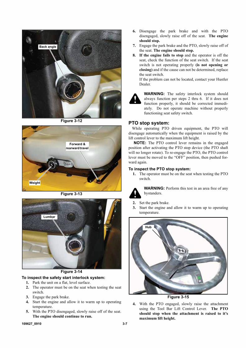
Seat adjustmentThe seat can be adjusted four different ways to obtain the
most comfortable position:1. Back angle (Figure 3-12)2. Forward and rearward travel (Figure 3-13)3. Weight (Figure 3-13)4. Lumbar (Figure 3-14)
Steering wheel adjustmentThe 3500/3700 is equipped with an adjustable steering
wheel which can telescope and tilt.To telescope the wheel, turn the wheel hub to the left and
raise or lower the steering wheel to the desired height. Thenturn the hub to the right to lock it into position. (Figure 3-15)NOTE: When locking the hub into position, do notovertighten.
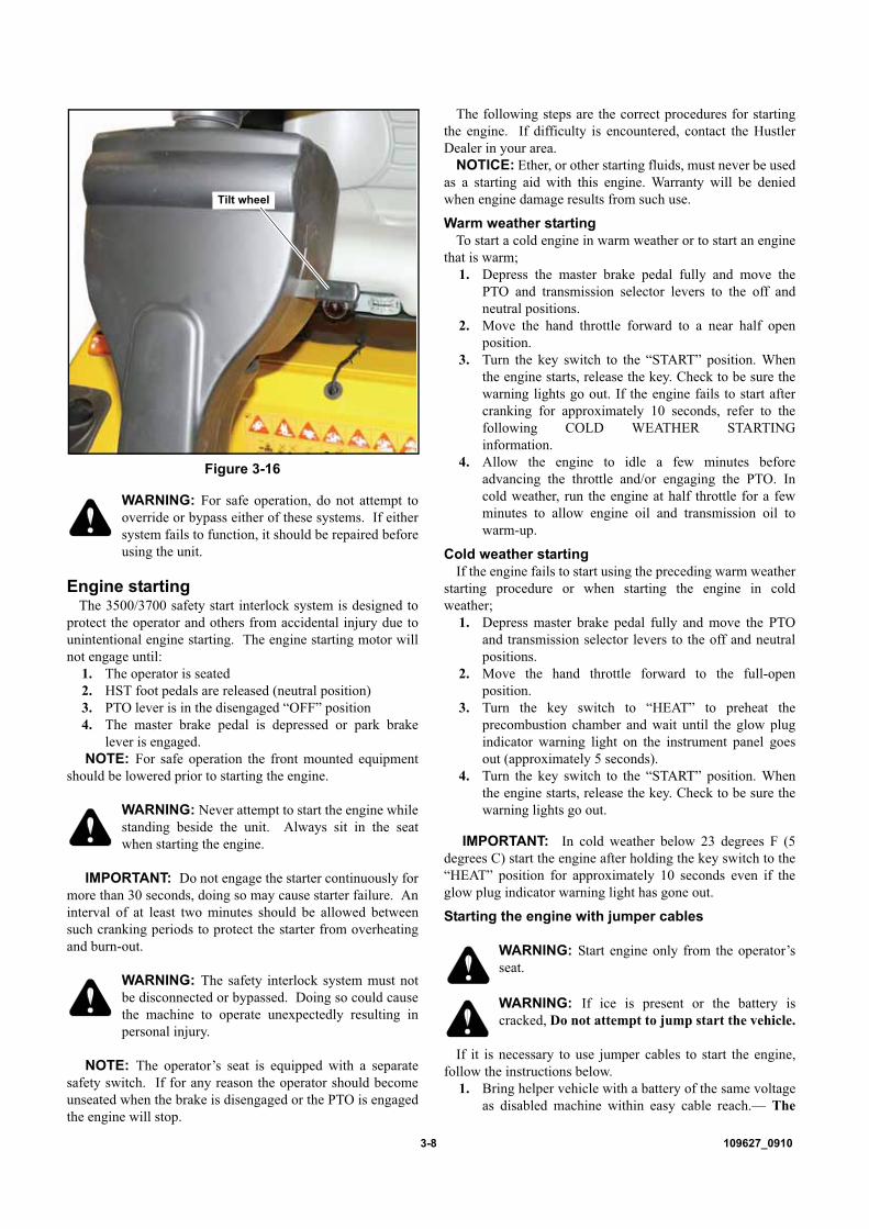
To tilt the wheel, pull up on the lever and move the steeringwheel fore or aft the desired position. If the wheel is not heldin position when the lever is raised, the steering wheel willspring to its most forward position. Use this feature to gainadditional clearance when mounting and dismounting thetractor. (Figure 3-16)
Safety start interlock systemThe tractor is equipped with a safety start interlock system
consisting of the brake switch, seat switch, PTO switch andtransmission neutral switch.
Check tractor safety start interlock system daily, priorto operation. This system is an important tractor safetyfeature. It should be repaired immediately if it malfunctions.The machine incorporates a separate seat switch which willstop the tractor engine when the operator is unseated for anyreason while the tractor is operating. This is a safety featuredesigned to prevent runaway or accidental entanglement.
Raising off the seat, the engine will stop wheneveroperating PTO driven equipment such as the mower deck.Also the engine will stop when raising off the seat unless theparking brake or master brake pedal is applied.
Figure 3-11
PTO Control Lever
Tool Bar Lift Control Lever
Weight Transfer Control
I
H
J
109627_0910 3-7
To inspect the safety start interlock system:1. Park the unit on a flat, level surface.2. The operator must be on the seat when testing the seat
switch.3. Engage the park brake.4. Start the engine and allow it to warm up to operating
temperature.5. With the PTO disengaged, slowly raise off of the seat.
The engine should continue to run.
6. Disengage the park brake and with the PTOdisengaged, slowly raise off of the seat. The engineshould stop.
7. Engage the park brake and the PTO, slowly raise off ofthe seat. The engine should stop.
8. If the engine fails to stop and the operator is off theseat, check the function of the seat switch. If the seatswitch is not operating properly (is not opening orclosing) and if the cause can not be determined, replacethe seat switch.If the problem can not be located, contact your HustlerDealer.
WARNING: The safety interlock system shouldalways function per steps 2 thru 6. If it does notfunction properly, it should be corrected immedi-ately. Do not operate machine without properlyfunctioning seat safety switch.
PTO stop system: While operating PTO driven equipment, the PTO will
disengage automatically when the equipment is raised by thelift control lever to the maximum lift height.
NOTE: The PTO control lever remains in the engagedposition after activating the PTO stop device (the PTO shaftwill no longer rotate). To re-engage the PTO, the PTO controllever must be moved to the “OFF” position, then pushed for-ward again.
To inspect the PTO stop system:1. The operator must be on the seat when testing the PTO
switch.
WARNING: Perform this test in an area free of anybystanders.
2. Set the park brake.3. Start the engine and allow it to warm up to operating
temperature.
4. With the PTO engaged, slowly raise the attachmentusing the Tool Bar Lift Control Lever. The PTOshould stop when the attachment is raised to it’smaximum lift height.
Figure 3-12
Figure 3-13
Figure 3-14
Back angle
Weight
Forward & rearward travel
Lumbar
Figure 3-15
Hub
3-8 109627_0910
WARNING: For safe operation, do not attempt tooverride or bypass either of these systems. If eithersystem fails to function, it should be repaired beforeusing the unit.
Engine startingThe 3500/3700 safety start interlock system is designed to
protect the operator and others from accidental injury due tounintentional engine starting. The engine starting motor willnot engage until:
1. The operator is seated2. HST foot pedals are released (neutral position)3. PTO lever is in the disengaged “OFF” position4. The master brake pedal is depressed or park brake
lever is engaged.NOTE: For safe operation the front mounted equipment
should be lowered prior to starting the engine.
WARNING: Never attempt to start the engine whilestanding beside the unit. Always sit in the seatwhen starting the engine.
IMPORTANT: Do not engage the starter continuously formore than 30 seconds, doing so may cause starter failure. Aninterval of at least two minutes should be allowed betweensuch cranking periods to protect the starter from overheatingand burn-out.
WARNING: The safety interlock system must notbe disconnected or bypassed. Doing so could causethe machine to operate unexpectedly resulting inpersonal injury.
NOTE: The operator’s seat is equipped with a separatesafety switch. If for any reason the operator should becomeunseated when the brake is disengaged or the PTO is engagedthe engine will stop.
The following steps are the correct procedures for startingthe engine. If difficulty is encountered, contact the HustlerDealer in your area.
NOTICE: Ether, or other starting fluids, must never be usedas a starting aid with this engine. Warranty will be deniedwhen engine damage results from such use.
Warm weather startingTo start a cold engine in warm weather or to start an engine
that is warm;1. Depress the master brake pedal fully and move the
PTO and transmission selector levers to the off andneutral positions.
2. Move the hand throttle forward to a near half openposition.
3. Turn the key switch to the “START” position. Whenthe engine starts, release the key. Check to be sure thewarning lights go out. If the engine fails to start aftercranking for approximately 10 seconds, refer to thefollowing COLD WEATHER STARTINGinformation.
4. Allow the engine to idle a few minutes beforeadvancing the throttle and/or engaging the PTO. Incold weather, run the engine at half throttle for a fewminutes to allow engine oil and transmission oil towarm-up.
Cold weather startingIf the engine fails to start using the preceding warm weather
starting procedure or when starting the engine in coldweather;
1. Depress master brake pedal fully and move the PTOand transmission selector levers to the off and neutralpositions.
2. Move the hand throttle forward to the full-openposition.
3. Turn the key switch to “HEAT” to preheat theprecombustion chamber and wait until the glow plugindicator warning light on the instrument panel goesout (approximately 5 seconds).
4. Turn the key switch to the “START” position. Whenthe engine starts, release the key. Check to be sure thewarning lights go out.
IMPORTANT: In cold weather below 23 degrees F (5degrees C) start the engine after holding the key switch to the“HEAT” position for approximately 10 seconds even if theglow plug indicator warning light has gone out.
Starting the engine with jumper cables
WARNING: Start engine only from the operator’sseat.
WARNING: If ice is present or the battery iscracked, Do not attempt to jump start the vehicle.
If it is necessary to use jumper cables to start the engine,follow the instructions below.
1. Bring helper vehicle with a battery of the same voltageas disabled machine within easy cable reach.— The
Figure 3-16
Tilt wheel

109627_0910 3-9
vehicles must not touch.2. Shield eyes.3. Connect one end of the jumper cable to the battery
positive (+) terminal and the other to the auxiliarybattery positive (+) terminal. Connect one end of theother cable first to the auxiliary battery (-) negativeterminal, and the other end to the Hustler tractor frame.Follow the starting procedures above after the jumpercables are connected as instructed.
4. After engine has started, disconnect the negativejumper cable before disconnecting the positive jumpercable(s).
WARNING: Battery posts, terminals, and relatedaccessories contain lead and lead compounds,chemicals known to the State of California to causecancer and reproductive harm. Wash hands afterhandling.
WARNING: Charge batteries in an open well venti-lated area, away from spark and flames. Unplugcharger before connecting or disconnecting from thebattery. Wear protective clothing and use insulatedtools.
WARNING: Avoid skin and clothing contact withbattery acid.
WARNING: Always wear eye protection whenchecking the battery, acid can cause serious injury toskin and eyes. If contact occurs, flush area withclean water and call physician immediately. Acidwill also damage clothing.
Do not drink the battery electrolyte.Do not allow open flame near the battery whencharging.Hydrogen gas forms inside the battery. This gas isboth toxic and flammable and may cause an explo-sion if exposed to flame. Always remove the nega-tive ground first and replace it last.Do not overfill battery.Electrolyte may overflow and damage paint, wiringor structure. When cleaning the battery, use soapand water. Be careful not to get soap and water intothe battery. Clean the battery terminals with a solu-tion of four parts water and one part baking sodawhen they become corroded.
WARNING: Shorts caused by battery terminals ormetal tools touching metal tractor components cancause sparks. Sparks can cause a battery gas explo-sion which will result in personal injury.
Prevent the battery terminals from touching anymetal tractor parts when removing or installing thebattery.Do not allow metal tools to short between the bat-tery terminals and metal tractor parts.
WARNING: Incorrect battery cable routing couldcause damage to the tractor and battery cables. Thiscan cause sparks which can cause a battery gasexplosion which will result in personal injury.
Always disconnect the negative (black) batterycable(s) before disconnecting the positive (red)cable(s).
WARNING: Always connect the positive (red) bat-tery cable(s) before connecting the negative (black)cable(s).
Engine warm upIn cold weather, run the engine at half throttle for a few
minutes to allow engine oil and transmission oil to warm up.
WARNING: Never leave the machine running unat-tended.
Stopping the engine
WARNING: Always apply the park brake whenleaving the seat.
Stopping the engine should be done according to thefollowing procedures;
1. Pull the throttle lever fully rearward to the low idleposition.
2. Release the HST foot pedals.3. Engage the parking brake.4. Place the transmission selector and lift control levers in
the “N” position.5. Turn the key start switch to the “OFF” position.6. Remove the key.
IMPORTANT: Failure to turn the key start switch to the“OFF" position, after the engine stops, will allow the warninglights to remain on, causing the battery to discharge.
IMPORTANT: Do not stop the engine immediately afterhard or extended operation. Keep the engine running at slowidle for about 2 minutes to allow engine to cool down.
Operating the hydrostatic transmission and PTOHydrostatic transmission
The hydrostatic transmission is controlled by the HST footpedals, cruise control switch, and transmission selector lever.Figure 3-5, Figure 3-8 & Figure 3-9
When operating the transmission selector lever, place theHST foot pedals in the neutral position. If it is difficult toengage, slightly depress the Forward or Reverse foot pedal forsmooth engagement.
Never engage or disengage the transmission selector leverwhen the unit is in motion.
With the transmission selector lever in “H” range (Figure 3-10), ground speed can be varied from zero to maximum bydepressing the forward or reverse travel pedal. In “L” range,speeds are about 60% of “H” range. Maximum speeds in
3-10 109627_0910
reverse are about a 65% of maximum forward speeds.To stop the unit, release the pedal gradually (except on an
emergency). When released, the pedal returns to the Neutralposition automatically, stopping the unit. Sudden release canresult in an abrupt, and possibly dangerous stop.
For prolonged operation at a fixed forward speed, use theforward travel pedal to attain the desired speed, then move thecruise control switch to the “ON” position. Speed will remainat the set value when the pedal is released.
To cancel the speed setting or stop, push the switch to the“OFF” position or firmly depress the master brake pedal.
Automatic or Locked All Wheel Drive (AWD) The transmission selector lever is used to select Automatic
Four-Wheel Drive or Locked Four-Wheel Drive.When the Transmission Selector lever is located in the
inside slot, the tractor will run in Automatic AWD mode.Figure 3-9
When the lever is placed in the outer slot, the mower willrun in Locked AWD mode and low range. Figure 3-10
When in motion, always bring the unit to a complete stopbefore moving the transmission selector lever.
Automatic All Wheel Drive (AWD) means that the four-wheel drive line is engaged automatically when the frontwheels start to slip, but, in normal operation, reverts to 2WD,this provides sharp and smooth turns without damaging turf.
Locked Four-Wheel Drive should be used when additionaltraction is required while operating in loose soil, wet, slipperyconditions or slopes.
NOTE: The steering (rear) axle is not powered in reversewhen tractor is operating in Automatic AWD.
Power take-off operationThe power take-off (PTO) transfers engine power directly
to the PTO equipment.PTO is controlled through the PTO lever. To engage the
PTO, push the lever forward. To disengage the PTO, pull thelever rearward. Figure 3-11
WARNING: To avoid personal injury, keep chil-dren and others away when operating PTO equip-ment.
NOTE: The PTO lever must be placed in the disengagedposition to start the tractor.
Operating the differential lockDo not engage the differential lock when ground speed is
above 5 mph (8 kmh). Figure 3-7The differential lock is engaged by depressing the
differential lock pedal. Depressing the pedal locks bothdifferential gears together, preventing one wheel from rotatingindependently of the other. The lock should be used to obtainadditional traction from the opposite wheel whenever onewheel begins to slip in wet or loose soil.
NOTE: The differential lock pedal only locks the frontaxle when applied. The rear axle is not lockable.
WARNING: Do not engage the differential lockwhen turning the unit. If the lock is engage whenturning, a loss of steering control will result.
To operate the differential lock depress and hold down thepedal until the lock is positively engaged. It is best to engagethe differential lock while the wheels are turning slowly tominimize shock loads to the drive line. If a wheel spins athigh speed, as on ice, reduce engine speed to idle beforeengaging the lock, or damage may occur. The differentiallock is released when the pedal releases as the loads equalizeson both drive wheels.
NOTE: In some instances the lock may remain engagedafter the pedal is released. This may occur if one front wheeltends to turn at a faster speed than the other. Should this hap-pen, the lock may be disengaged by decreasing the drawbarpull by raising or disengaging the implement so that neitherwheel tends to slip.
Operating the hydraulic lift systemThe hydraulic lift system provides hydraulic power for
raising front mounted equipment whenever the engine isrunning.
To raise the front mounted equipment, pull the lift controllever rearward and hold it until the desired equipment heightis reached. Figure 3-11
To lower the equipment, push the lever forward. Whenpushed all the way forward, the lever will remain in a loweredfloat detent position.
IMPORTANT: Always set the lift control lever in thefloat detent position when mowing.
WARNING: Make sure the area is clear of peoplebefore raising or lowering equipment.
WARNING: Always lower the hydraulic lift andequipment before stopping the unit.
Weight transfer valveThe weight transfer valve is used to transfer the front
attachment weight to the tractor unit to reduce equipmentweight on turf and prevent damage and improve front drivewheel traction. Figure 3-11
The weight transfer valve should be used according to thefollowing procedures;
1. With the engine running, push the hydraulic lift leverforward to the floating position.
2. Turn the adjusting knob clockwise until the mower orother equipment lifts off the ground.
3. Turn the adjusting knob counter-clockwise slowly untilthe mower deck front gauge wheels or other equipmentjust touches the ground, then turn the knob counter-clockwise 1/4 turn more.
4. Operate the unit over uneven terrain at desired travelspeed and observe the mower deck’s front gaugewheels. If the wheels or equipment do not followground contour, the operation will be affected.
5. To correct this condition, turn the knob 1/4 turnclockwise at a time until the mower deck’s front gaugewheels follow the ground contour.
Auxiliary hydraulic valve kit (optional)An Auxiliary Hydraulic Valve kit is available from your
Hustler Dealer, as an option. When using the auxiliary valve,

109627_0910 3-11
the lift control lever must remain in neutral. Figure 3-17 andFigure 3-18
This kit includes control valves, hoses and quick connectcouplers for supplying hydraulics power to optionalattachments. When not in use, the coupler dust covers must bein place to prevent contamination. Always replace themimmediately if damaged or lost. Note the hydraulic circuitconnectors called out in Figure 3-18.
Once connected, the operator has control of theattachment’s hydraulic cylinder by means of the valve controllevers. If stroking the valve lever produces the wrong cylindermovement (up-down, right-left, etc.), reverse the attachmenthoses at the quick connect couplers. Use of the valve controllever varies with each attachment and is described in moredetail in the operating instructions provided with theattachment.
WARNING: Never attempt to connect or discon-nect the couplers with the hydraulics engaged andthe system oil under pressure.
Rear counter-balance weights
WARNING: Improper operation on slopes cancause injury. Install rear counter-balance weights,when the attachment is installed, to increase stabil-ity. Use extreme care when operating on slopes.
Rear counter-balance weights are required to improvestability, steering and traction. They also reduce tire lift offwhen attachments are raised, operated on slopes or during anabrupt stop. Refer to Figure 3-19 for weight attachment.
Refer to the attachment’s owner’s manual for the properweight amount and weight part number.
ROPS(Roll Over Protective Structure)
A Roll Over Protective Structure (ROPS) and seat belt arestandard equipment. Do not remove the ROPS and seat belt.ROPS when used with seat belt is effective in reducinginjuries during unit overturn accidents. Overturning the unitwithout ROPS can result in serious injury or death.
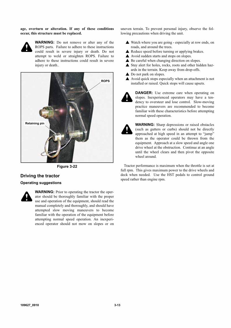
NOTE: Inspect the ROPS after the first 20 hours of opera-tion. Following the initial inspection, check the ROPS afterevery 500 hours of operation or every six months, whichevercomes first. Figure 3-20
1. Check the torque of the ROPS mounting bolts. Tightenthe bolts to the correct torque of 72 ft.-lbs. (97 Nm) ifnecessary. Figure 3-21
2. Inspect the operator’s seat and the mounting parts forthe seat belt. Tighten the bolts to the correct torque of72 ft.-lbs. (50.0 Nm) if necessary and replace parts thatshow wear or damage.
The two-post ROPS can be pivoted down by removing theright and left retaining rings and pulling out on the pins so thatthe machine can operate under low hanging tree limbs orother obstructions. (Figure 3-22) Do not wear the seat belt
Figure 3-17
Figure 3-18
Auxiliary control valve levers
Quick couplers
Inside lever Port A
Inside lever Port B
Outside lever Port A
Outside lever Port B
Figure 3-19
WeightsA/R
Weight attaching bracket

3-12 109627_0910
when the ROPS is in the lowered position. Use the ROPS inthe “folded” position only when it is absolutely necessary.
WARNING: Do not operate the mower with theROPS folded (lowered position) as a standard oper-ating mode. A folded ROPS does not provide roll-over protection.
WARNING: Always wear your seat belt unless thetractor is not equipped with a ROPS or safety cab orif the ROPS is folded down. In this case, the seatbelt should never be worn.
WARNING: To minimize chance of injury or deathfrom rollover: keep ROPS in the raised and lockedposition and use the seat belt.Never operate machine on a slope with the ROPSfolded down (lowered position).There is no roll over protection when the ROPS is inthe lowered position.Lower the ROPS only when absolutely necessary.Drive slowly and carefully. Raise the ROPS as soonas clearance permits. Read and follow slope opera-tion instructions and warnings.Do not wear seat belt when the ROPS is in the low-ered position.
WARNING: Always pull from the tractor hitch. Donot attach chains or ropes to the ROPS for pullingpurposes,as the machine can tip backwards.
Always fasten seat belt during operation of the machinewith ROPS in “raised/up” position. Figure 3-20
Inspect the area to be mowed for proper overhead clearance(tree limbs, guy wires, doorways, etc)
Do not contact any overhead object with the ROPS.Inspect the seat belt system (all seat, seat belt parts, seat pan
and seat pan latch) daily prior to mowing for signs of anydamage. These parts should be replaced if any parts indicatesigns of:
1. cuts2. fraying3. extreme or unusual wear4. significant discoloration due to UV exposure5. dirt or stiffness6. abrasion to the seat belt webbing7. damage to the buckle, latch plate or hardware.8. or any other problem
If the seat belt is to be cleaned, use soap and water. Do notuse carbon tetrachloride, naphtha, etc., as these will weakenthe webbing. For the same reason, do not bleach or dye thewebbing. Replace seat belt if worn or damaged.
Possible damage to the ROPSIf the unit has rolled over or the ROPS has been in some
other type of accident (such as hitting an overhead objectduring transport), the ROPS must be replaced to retain thebest protection.
Following an accident, check the ROPS, the operator’s seat,and the seat belt and seat belt mountings for possible damage,Before operating the machine, replace all damaged parts.
IMPORTANT: Do not attempt to weld or straighten theROPS.
WARNING: If the ROPS or cab is removed orreplaced, make sure that the proper hardware is usedand the recommended torque values are applied tothe attaching bolts.
WARNING: The ROPS structure’s protectivecapability may be impaired by structural dam-
Figure 3-20
Figure 3-21
ROPS
Bolts
ROPSBolts
109627_0910 3-13
age, overturn or alteration. If any of these conditionsoccur, this structure must be replaced.
WARNING: Do not remove or alter any of theROPS parts. Failure to adhere to these instructionscould result in severe injury or death. Do notattempt to weld or straighten ROPS. Failure toadhere to these instructions could result in severeinjury or death..
Driving the tractorOperating suggestions
WARNING: Prior to operating the tractor the oper-ator should be thoroughly familiar with the properuse and operation of the equipment, should read themanual completely and thoroughly, and should haveattempted slow moving maneuvers to becomefamiliar with the operation of the equipment beforeattempting normal speed operation. An inexperi-enced operator should not mow on slopes or on
uneven terrain. To prevent personal injury, observe the fol-lowing precautions when driving the unit.
� Watch where you are going - especially at row ends, onroads, and around the trees.
� Reduce speed before turning or applying brakes.� Avoid sudden starts and stops on slopes.� Be careful when changing direction on slopes.� Stay alert for holes, rocks, roots and other hidden haz-
ards in the terrain. Keep away from drop-offs.� Do not park on slopes.� Avoid quick stops especially when an attachment is not
installed or raised. Quick stops will cause upsets.
DANGER: Use extreme care when operating onslopes. Inexperienced operators may have a ten-dency to oversteer and lose control. Slow-movingpractice maneuvers are recommended to becomefamiliar with these characteristics before attemptingnormal speed operation.
WARNING: Sharp depressions or raised obstacles(such as gutters or curbs) should not be directlyapproached at high speed in an attempt to “jump”them as the operator could be thrown from theequipment. Approach at a slow speed and angle onedrive wheel at the obstruction. Continue at an angleuntil the wheel clears and then pivot the oppositewheel around.
Tractor performance is maximum when the throttle is set atfull rpm. This gives maximum power to the drive wheels anddeck when needed. Use the HST pedals to control groundspeed rather than engine rpm.
Figure 3-22
Retaining pin
ROPS

3-14 109627_0910

109627_0910 4-1
MAINTENANCE & ADJUSTMENTS
Safe Servicing PracticesIMPORTANT: This product is capable of amputating
hands and feet and throwing objects. Always follow all safetyinstructions to avoid serious injury or death.
Service� Unless specifically required, DO NOT have engine
running when servicing or making adjustments to trac-tor. Park the machine on level ground. Place parkbrake lever in the brake engaged position, place thePTO lever in the “OFF” position, lower attachment,remove ignition switch key and disconnect negativebattery cable before doing any maintenance. Wait forall movement to stop before adjusting, cleaning orrepairing. Repairs or maintenance requiring enginepower should be performed by trained maintenancepersonnel only. To prevent carbon monoxide poison-ing, be sure proper ventilation is available when enginemust be operated in an enclosed area. Read andobserve safety warnings in front of manual.
� Before working on or under the deck, make certainengine cannot be accidentally started. Shut engine off,remove ignition switch key, engage park brake and dis-connect negative battery cable for maximum safety.Repairs or maintenance requiring engine power shouldbe performed by trained maintenance personnel only.
� Except when changing or checking belt, always keepsafety shields and covers in place.
� Use a stick or similar instrument to clean under themower making sure that no part of the body, especiallyarms and hands are under mower.
� Keep your machine clean and remove any deposits oftrash and clippings, which can cause engine fires andcooling system overheating as well as excessive beltwear. Clean up oil or fuel spillage. Allow machine tocool before storing.
� Clean flammable material from machine. Preventfires by keeping the top of the deck, engine com-partment, radiator screen, front screen, exhaustarea, battery, hydraulic lines, fuel line, fuel tankand operator’s station clean of accumulated trash,grass clippings, and other debris. Always clean upspilled fuel and oil.
� Always wear adequate eye protection when servicingthe hydraulic system, cooling system, battery or whengrinding mower blades and removing accumulateddebris.
� Use extra caution when handling diesel fuel. It is flam-mable and vapors are explosive.
� Never attempt to start engine when there is a strongodor of diesel fumes present. Locate and correctcause.
� Never remove fuel cap or refuel tractor while engine isrunning; never refuel near an open flame or neardevices which can create a spark. Refuel outdoors.Never refuel or drain the fuel from the machineindoors.
� Never run the engine in an enclosed area unlessexhaust is vented to the outside. Exhaust gases containcarbon monoxide which is odorless and deadly poison.
� Never attempt to make any adjustments or repairs tothe tractor drive system, mower deck or any attachmentwhile the tractor engine is running or PTO is engaged.Repairs or maintenance requiring engine power shouldbe performed by trained maintenance personnel only.
� Never work under the machine or attachment unless itis safely supported with jack stands. Make certainmachine is secure when it is raised and placed on thejack stands. The jack stands should not allow themachine to move when the engine is running and thedrive wheels are rotating. Use only certified jackstands. Use only appropriate jack stands, with a mini-mum weight rating of 3500 pounds to block the unitup. Use in pairs only. Follow the instructions suppliedwith the vehicle stands.
� Do not touch hot parts of machine.� Keep nuts and bolts tight, especially the blade attach-
ment bolts. Keep equipment in good working condi-tion.
� Never tamper with safety devices. Check their properoperation daily.
� Stop the engine before removing the grass catcher orunclogging the discharge chute. Never clear the dis-charge chute with the engine running. Turn off theengine and be sure the blades have stopped beforecleaning. Use a stick to clear a plugged discharge area.Never use your hand!
� Grass collection system components are subject towear, damage and deterioration, which could exposemoving parts or allow objects to be thrown. Frequentlycheck components and replace with manufacturer’srecommended parts, when necessary.
� Exercise caution when working under the deck as themower blades are extremely sharp. Wrap the blade(s)or wear gloves and use extra caution when servicingthem. Take care as the rotation of one blade can causethe other blades to rotate.
� Use only genuine Hustler replacement parts to ensurethat original standards are maintained
IntroductionRegular maintenance is the best prevention for costly
downtime or expensive, premature repair. The followingpages contain suggested maintenance information andschedules which the operator should follow on a routine basis.For more detailed information order the correct parts manualfor your unit. Refer to the Product Literature section of thismanual.
Remain alert for unusual noises, they could be signaling aproblem. Visually inspect the machine for any abnormal wearor damage. A good time to detect potential problems is whileperforming scheduled maintenance service. Correcting theproblem as quickly as possible is the best insurance.
Clear away heavy build-up of grease, oil and dirt, especiallyin the engine and under the seat platform areas; minute dust

4-2 109627_0910
particle are abrasive to close-tolerance engine and hydraulicassemblies.
Daily inspect mower for grass clippings and wire andstring tangles. The underside of the mower deck will collecta build-up of grass clippings and dirt, especially when grassis wet or has high moisture content. This build-up willharden, restricting blade and air movement and will probablyshow a poorer quality of cutting. Therefore it should beremoved routinely.
To do this it will be necessary to raise and block the deck,using jack stands or blocks, in the full up position and scrapethe build-up from underneath. Refer to the deck owner’smanual for more detailed information.
Some repairs require the assistance of a trained servicemechanic and should not be attempted by unskilledpersonnel. Consult your Hustler service center whenassistance is needed.
Torque valuesIMPORTANT:
WARNING: Particular attention must be given totightening the drive wheel lug bolts and blade spin-dle bolts. Failure to correctly torque these itemsmay result in the loss of a wheel or blade, whichcan cause serious damage or personal injury.
Torque values are given below:Ft-lbs. Nm
Wheel (lug) bolts - front . . . . 85-95 . . . . . . 115-129Wheel (lug) bolts - rear . . . . . 65-75 . . . . . . 88.1-101.7Deck blade (top) bolts . . . . . . 65-75 . . . . . . 88.1-101.7Deck blade (bottom) bolts . . . 118 . . . . . . . . 160.01
Lug bolts only - It is recommended that these be checkedafter the first 2 hours of operation, initially, every 50 hoursand following removal for repair or replacement.
For all other torques refer to the various tractor partsmanuals for standard torque chart. See the Product Literaturesection of this manual for ordering information.
For engine torque values, see engine service manual.
TiresIt is important that the tires have an equal amount of air
pressure. The recommended pressure are:Front wheels. . . . . . . . . . . . 14-18 psi (96-124 KPa)Rear wheels . . . . . . . . . . . . 14-18 psi (96-124 KPa)
Solid fill tires are not recommended for Hustler turfequipment. On any machine, with solid filled tires, thewarranty claim will be denied.
LubricationEngine Oil . . . . . . . . . . . . . . . See Chart belowTransmission Oil . . . . . . . . . . ISO VG 46Grease . . . . . . . . . . . . . . . . . . SAE multi-purpose grease
Lubrication fittingsNOTE: After every 50 hours of normal operation, apply a
good quality grease to the lubrication points listed below(refer to the Recommended Lubricants chart). When operat-ing under extremely dirty conditions, lubricate more fre-quently than every 50 hours.
• Lift cylinder• Front Lift arm• Power Steering Cylinder• Brake pedal shaft• Differential Lock pedal shaft
To lubricate these points:1. Wipe away all old grease and dirt from the lubrication
fittings to prevent dirt or foreign material fromentering as new grease is applied.
2. Use a high pressure grease gun to force in the newgrease. Apply pressure until clean grease oozes fromeach lubrication point.
3. Wipe away any excess grease.
Service accessOpening the hood
WARNING: To avoid personal injury from contactwith moving parts:Never open the hood and seat while the engine isrunning.Do not touch the muffler or exhaust pipe while theyare hot; severe burns could result.
Unlock the hood latch. Raise the hood using the hoodhandle. Figure 4-1
Close the hood and clamp the hood latch.
Opening the seat platformPull out on the seat release knob and pivot the seat platform
forward. Figure 4-2
Electrical systemThe electrical system is a 12-volt DC system with negative
ground. The recommended battery size is a BCI group 35, 12-volt
battery with a minimum cold cranking ability of 490 amps at-18°C (0°F). A maintenance-free battery is recommended.Otherwise, follow battery manufacturer’s maintenance,safety, storing and charging specifications. Refer toMaintenance Locator Chart found elsewhere in this manual.
Recommended oils
Ambient Temperature Recommended oil
+ 40° — 120°F (+4.4° — 48.9°C) SAE 30W
+ 10° — 120°F (+12.2° — 48.9°C) SAE 15W-40
– 10° — 120°F (-23.3° — 48.9°C) SAE 10W-30
– 20° — 60°F (-28.9° — -15.6°C) SAE 5W-30
NOTE: Engine originally shipped with 10W-30 oil.
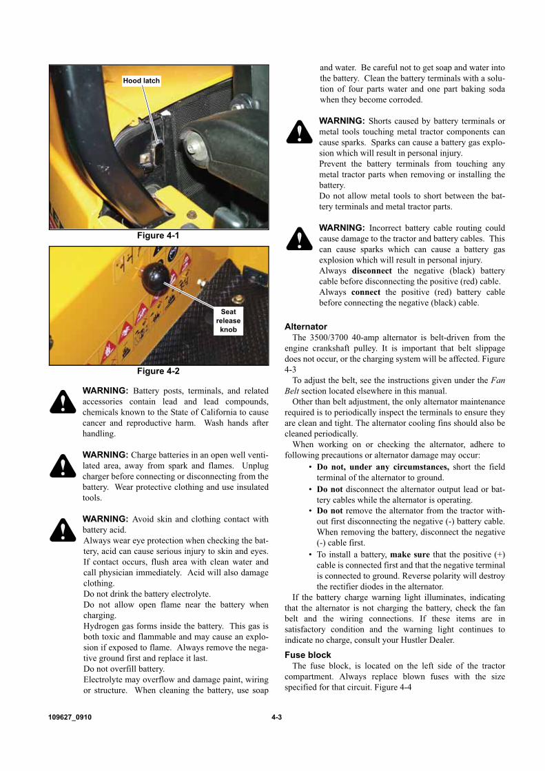
109627_0910 4-3
WARNING: Battery posts, terminals, and relatedaccessories contain lead and lead compounds,chemicals known to the State of California to causecancer and reproductive harm. Wash hands afterhandling.
WARNING: Charge batteries in an open well venti-lated area, away from spark and flames. Unplugcharger before connecting or disconnecting from thebattery. Wear protective clothing and use insulatedtools.
WARNING: Avoid skin and clothing contact withbattery acid.Always wear eye protection when checking the bat-tery, acid can cause serious injury to skin and eyes.If contact occurs, flush area with clean water andcall physician immediately. Acid will also damageclothing.Do not drink the battery electrolyte.Do not allow open flame near the battery whencharging.Hydrogen gas forms inside the battery. This gas isboth toxic and flammable and may cause an explo-sion if exposed to flame. Always remove the nega-tive ground first and replace it last.Do not overfill battery.Electrolyte may overflow and damage paint, wiringor structure. When cleaning the battery, use soap
and water. Be careful not to get soap and water intothe battery. Clean the battery terminals with a solu-tion of four parts water and one part baking sodawhen they become corroded.
WARNING: Shorts caused by battery terminals ormetal tools touching metal tractor components cancause sparks. Sparks can cause a battery gas explo-sion which will result in personal injury.Prevent the battery terminals from touching anymetal tractor parts when removing or installing thebattery.Do not allow metal tools to short between the bat-tery terminals and metal tractor parts.
WARNING: Incorrect battery cable routing couldcause damage to the tractor and battery cables. Thiscan cause sparks which can cause a battery gasexplosion which will result in personal injury. Always disconnect the negative (black) batterycable before disconnecting the positive (red) cable.Always connect the positive (red) battery cablebefore connecting the negative (black) cable.
AlternatorThe 3500/3700 40-amp alternator is belt-driven from the
engine crankshaft pulley. It is important that belt slippagedoes not occur, or the charging system will be affected. Figure4-3
To adjust the belt, see the instructions given under the FanBelt section located elsewhere in this manual.
Other than belt adjustment, the only alternator maintenancerequired is to periodically inspect the terminals to ensure theyare clean and tight. The alternator cooling fins should also becleaned periodically.
When working on or checking the alternator, adhere tofollowing precautions or alternator damage may occur:
• Do not, under any circumstances, short the fieldterminal of the alternator to ground.
• Do not disconnect the alternator output lead or bat-tery cables while the alternator is operating.
• Do not remove the alternator from the tractor with-out first disconnecting the negative (-) battery cable.When removing the battery, disconnect the negative(-) cable first.
• To install a battery, make sure that the positive (+)cable is connected first and that the negative terminalis connected to ground. Reverse polarity will destroythe rectifier diodes in the alternator.
If the battery charge warning light illuminates, indicatingthat the alternator is not charging the battery, check the fanbelt and the wiring connections. If these items are insatisfactory condition and the warning light continues toindicate no charge, consult your Hustler Dealer.
Fuse blockThe fuse block, is located on the left side of the tractor
compartment. Always replace blown fuses with the sizespecified for that circuit. Figure 4-4
Figure 4-1
Figure 4-2
Hood latch
Seat release knob

4-4 109627_0910
Fusible linkA fusible link wire is used to protect the mower’s entire
electrical system. If too much amperage passes through thiswire it will melt down so that it will no longer allow current topass (similar to the way a fuse works). The fusible link wire isa red wire that goes from the starter terminal to a connector
that links into the main wiring harness.To replace the fusible link wire (Figure 4-5):1. Order Hustler part number 385603370.2. Disconnect the negative battery cable from the battery.3. Unplug the connector linking the wire to the main
wiring harness.4. Remove the old fusible link wire from the starter
terminal.5. Replace the old fusible link wire with a new one-first
attaching to starter terminal, and then connecting intothe main wire harness.
IMPORTANT: Always replace the fusible link wire withthe appropriate fusible link wire for this tractor.
Head lampIf a head lamp fails to operate, the bulb must be replaced.
To change the bulb:1. Pull the lower cover frontward and remove it. Figure 4-
62. Turn the socket counterclockwise and remove the
socket from the headlamp housing.3. Remove the bulb. Figure 4-74. Install a new bulb in the socket and install the socket
with bulb in the housing.5. Install the front cover.
Replacement bulb:Head Lamp Bulb Type . . . . JIS S25 BA15 12V 23W
Instrument panel lightTo change a burned out instrument bulb:
1. Pull the lower cover frontward and remove it. Figure 4-7
2. Remove the four screws that connect the front cover tothe dashboard. Figure 4-8
3. Remove the front cover of the dashboard. Figure 4-84. Turn the burned out bulb together with the socket half a
turn counterclockwise and pull it out. Figure 4-95. Replace the bulb with new one and return the bulb and
socket to the original place.6. Re-attach the front cover and lower cover.
Replacement bulbs:Indicator Bulb Type. . . . . . . JIS T6.4 14V 3W (Qty 5)
Figure 4-3
Fuse Size Circuit protected
1 20 amp Spare
2 20 amp Auxiliary P.T.O., Work lamp (opt), backbuzzer (opt)
3 20 amp Auxiliary
4 10 amp Spare
5 10 amp Head lamp, meter back light, stopsolenoid, safety switch, starter, cruisecontrol (opt)
6 10 amp Temperature gauge, fuel gauge, fuelpump, monitor lamp, Alarm buzzer & relay
Figure 4-4
Alternator
Fuse block ��� ���
Figure 4-5
Fusible link

109627_0910 4-5
Indicator Bulb Type . . . . . . . JIS T5 13.5V 2W (Qty 1)
Fuel system
DANGER: To avoid personal injury or propertydamage, use extreme care in handling diesel fuel.Diesel fuel is extremely flammable and the vaporsare explosive.
DANGER: Observe usual fuel handling precau-tions:Do not smoke while refueling or anywhere nearfuel. Extinguish all cigarettes, cigars, pipes and
other sources of ignition.Do not remove fuel cap or fill tank with engine run-ning or while engine is hot. Clean up any diesel fuelspills immediately.Always tighten the fuel cap securely.Allow engine to cool before storing machine insidea building.Keep fuel away from open flame or spark and storemachine away from open flame or spark or pilotlight such as on a water heater or other appliances. Use extreme care when handling diesel fuel. It isextremely flammable and vapors are explosive. Afire or explosion from diesel fuel can burn you andothers and can damage property.Never refuel or drain the diesel fuel from themachine indoors.Never attempt to start engine when there is a strongodor of diesel fuel fumes present. Locate and cor-rect cause.
Figure 4-6
Figure 4-7
Figure 4-9
Lower cover
Light bulb& socket
Instrument lights
Figure 4-8
Screw
Screw
Front cover

4-6 109627_0910
Store diesel fuel in an approved container and keep itout of the reach of children. Do not fill diesel fuel containers inside a vehicle oron a truck or trailer bed with interior carpets or plas-tic truck bed liners. Always place diesel fuel con-tainers on the ground away from your vehicle beforefilling.When practical, remove diesel fuel-powered equip-ment from the truck or trailer and refuel the equip-ment with its wheels on the ground. If this is notpossible, then refuel such equipment on the truck ortrailer using a portable container and not a fuel dis-penser nozzle. If a fuel dispenser nozzle must beused, keep the nozzle in contact with the rim of thefuel tank or container opening at all times until fuel-ing is complete. Do not use a nozzle lock-opendevice.Never use diesel fuel or gasoline for cleaning parts.Read and observe safety precautions elsewhere inthis manual.
WARNING: Diesel fuel is harmful or fatal if swal-lowed.Long-term exposure to vapors can cause seriousinjury and illness.Avoid prolonged breathing of vapors.Keep face away from nozzle and fuel tank or dieselfuel container opening.Keep diesel fuel away from eyes and skin.If diesel fuel is spilled on clothing, change clothingimmediately.
WARNING: Under no circumstances should gas-oline, alcohol, or gasohol be added to diesel fuel.These combinations can create an increased fire orexplosive hazard.
WARNING: Fuel System Under Pressure! Fuel inthe injection system is under high pressure and canpenetrate the skin. Unqualified persons should notremove or attempt to adjust a pump injector, nozzleor any part of the fuel injection system.Do not use your hand to check for leaks. Use a pieceof cardboard or paper to search for leaks.If any fluid is injected into the skin, obtain medicalattention immediately or gangrene may result.Failure to follow these instructions can result in seri-ous injury.Check the fuel line periodically as it is subject towear and aging, fuel may leak onto the engine whichcould cause a fire.
IMPORTANT: Do not fill tank to capacity. Allow roomfor expansion.
IMPORTANT: If the original fuel tank cap is lost, alwaysreplace it with a Hustler approved cap. A “will fit cap” maynot be safe.
Diesel fuel• Use clean, quality No. 1-D or No. 2-D fuel
• Use No. 1-D fuel if the ambient temperature isexpected to be lower than 39 degrees F (4 degrees C)or if the tractor is to be used at an altitude exceeding5000 ft. (1524 m).
• Use diesel fuel with a pour point of at least 10°F(12°C) below the expected ambient temperature toprevent fuel flow problems in cold weather.
• Keep dirt from entering the fuel tank.• Sulfur content of the fuel should be no more than
0.05%.• Sediment and water content should not exceed
0.05%.• Minimum cetane number is 40. Low temperature or
high altitude operation may require use of fuel with ahigher Cetane number.
• Use properly mixed winter fuel when temperaturesare extremely cold. In most areas, diesel fuel is prop-erly blended for summer and winter grades as ambi-ent temperatures change. In winter, use winter gradediesel fuel only. Otherwise, the fuel may cloud andblock the fuel system.
Refueling the TractorThe fuel tank filler cap is located at the left side of the
tractor hood. Before removing the cap, wipe all dust and dirtfrom around the cap to prevent debris from falling into thetank while filling. Figure 4-10
Use an approved fuel container and check the inside of thecontainer periodically for cleanliness. Fuel tank capacity is13.33 gallons (50.5L).
NOTE: The fuel cap is a vented-type. Use only anapproved Hustler replacement cap to prevent fuel system-related problems.
If there is no filter on the storage tank or fuel container,filter the fuel through a 100-mesh or finer screen when fillingthe mower fuel tank. Keep the mower tank as full as possible(without filling to capacity) to minimize condensation.
NOTE: It is a good practice to fill the fuel tank at the endof each day, as this will reduce overnight condensation.
Figure 4-10
Fuel cap

109627_0910 4-7
Fuel filterDraining the fuel filter:
NOTE: The fuel filter should be drained after every 100hours of operation.
1. Make sure there is adequate fuel in the fuel tank andclose the fuel shutoff valve (the handle should bepointing to the “C” position.) Remove the fuelsediment bowl. Figure 4-12
2. Open the fuel shutoff valve until all water has beenremoved and only fuel flows from the filter base.
3. Install the fuel sediment bowel. The fuel system isauto bleeding And does not require any manualbleeding procedures.
Changing the fuel filter:NOTE: Change the diesel fuel filter every 200 operating
hour.1. Close the shutoff valve (the handle should be pointing
to the “C” position). Figure 4-122. Remove the sediment bowl by rotating the retaining
nut Ref. No. 1. Figure 4-12
3. Open the fuel shutoff valve Ref. No. 2, to drain anyremaining water from the tank. Figure 4-12
4. Discard the fuel element Ref. No. 3, and install a newelement. Figure 4-12
5. Inspect the O rings Ref. No. 4 & 5 and replace ifnecessary. Figure 4-12
6. Install and securely tighten the sediment bowl.7. Open the fuel shutoff valve (the handle should be
pointing to the “O” position), so fuel will flow to thefilter. Figure 4-12
8. Bleed the fuel filter and injection pump as describedbelow in Bleeding the Fuel System.
Bleeding the fuel systemIMPORTANT:
The 3500/3700 fuel system is designed to bleedautomatically.
1. When the fuel tank is emptyFill until the fuel level of the tank is at least half full,then wait about one minute for air to dissipate.
2. When the fuel filter has been replaced:After replacing the filter, open the fuel shutoff valve.Air will dissipate for about one minute
NOTE: Fuel tank fuel level must be half full or more forauto bleed system to function correctly.
NOTE: The 3500/3700 is an auto bleeding system. Nomanual bleeding procedures needed.
Engine oil and filterChecking the Engine Oil Level
Check engine oil daily. Tractor must be setting level andthe engine stopped for a period of time when checking oillevel. Refer to engine manual and maintenance schedulefor oil recommendation and capacities.
Change the engine oil and filter every 100 hours orannually, whichever comes first.
NOTE: If tractor is being operated in extremely dirty con-ditions, then it is recommended oil be changed more fre-quently. If the engine is operated for extended periods of timeat maximum rated power and speed or under other types ofcontinuous, severe operating conditions the oil and filtershould be changed at 70 hours intervals following the initialoil change.
Refer to Figure 4-13 for the engine oil filter and dipsticklocation.
Refer to Figure 4-14 for the engine oil fill location.Refer to Figure 4-15 for the engine oil drain location.
Changing the oil1. Before adding engine oil, place the unit on a level
surface, then remove the dipstick to provide crankcaseventilation.
2. Add oil at the oil fill shown. Figure 4-14NOTE: When changing the engine oil, add the exactamount specified in the engine owner’s manual.NOTE: Use CD grade or better by API classificationengine oil.
3. Wait about fifteen minutes until the oil gets down tothe oil pan. Then check the oil level with a dipstick. A
Figure 4-11
Sediment bowl
O
C
Shut-offvalve
Open
Closed
Shown in Open position
Figure 4-12

4-8 109627_0910
certain period of time is required before the engine oilcompletely flows down from the oil filler to thecrankcase.
4. Check the oil level, accounting for the higher oil leveldue to the oil filter oil capacity.
Engine air filterPerform engine air filter maintenance per the Service
Interval chart shown elsewhere in this manual.A specially designed dry filter is standard equipment on
these tractors and supplies clean combustion air to the engine.Figure 4-16 Change the filter whenever the Air CleanerRestriction Warning Light comes on. Figure 3-1
These units are equipped with a safety filter. The filterelement slides over the safety filter. NOTE: For maximum
engine protection and air cleaner service life, install a newinner safety element every third primary element change orafter every 1000 hours of operation, whichever comes first.
NOTE: The safety filter does not require servicing unlessit becomes contaminated with dirt or moisture.
Recommended service procedure1. Release clamps and remove element. Clean the
canister with a damp cloth.2. Before installing a new element, inspect it by
placing a bright light inside and rotate the elementslowly, looking for any holes or tears in the paper.Also check gaskets for cuts or tears. Do not attempt touse a damaged element which will allow abrasiveparticles to enter the engine.
3. Install the new element and reinstall the dust cup.Make sure it seals all the way around the air cleanerbody, then tighten the clamps.
4. Check all fittings and clamps periodically fortightness and inspect hoses for holes or cracks.
5. Periodically check the intake hose for signs ofingested dust. Locate and repair the source of ingesteddirt.
6. Never operate a machine without an air filterinstalled.
OverservicingOverservicing occurs when an air filter element is removed
for cleaning or replacement before it is necessary. Each timethe filter is removed a small amount of dirt and dust could fallin the intake system. This accumulated dirt can cause adusted engine. It only takes a few grams of ingested dirt overthe normal service life of an engine to cause a dusted engine.
Do not clean element, replace with a new element only.Cleaning used air filter elements, through improper cleaningprocedures, can get dust on the inside of the filter causing dirtingestion and engine failure.
Figure 4-13
Figure 4-14
Engine oil filler
Dipstick
Engine oil fill cap
Figure 4-15
Engine oil drain
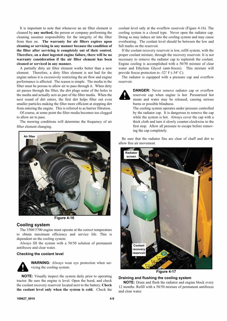
109627_0910 4-9
It is important to note that whenever an air filter element iscleaned by any method, the person or company performing thecleaning assumes responsibility for the integrity of the filterfrom then on. The warranty for air filters expires uponcleaning or servicing in any manner because the condition ofthe filter after servicing is completely out of their control.Therefore, on a dust ingested engine failure, there will be nowarranty consideration if the air filter element has beencleaned or serviced in any manner.
A partially dirty air filter element works better than a newelement. Therefore, a dirty filter element is not bad for theengine unless it is excessively restricting the air flow and engineperformance is affected. The reason is simple. The media in thefilter must be porous to allow air to pass through it. When dirtyair passes through the filter, the dirt plugs some of the holes inthe media and actually acts as part of the filter media. When thenext round of dirt enters, the first dirt helps filter out evensmaller particles making the filter more efficient at stopping dirtfrom entering the engine. This is referred to as barrier filtration.
Of course, at some point the filter media becomes too cloggedto allow air to pass.
The mowing conditions will determine the frequency of airfilter element changing.
Cooling systemThe 3500/3700 engine must operate at the correct temperature
to obtain maximum efficiency and service life. This isdependent on the cooling system.
Always fill the system with a 50/50 solution of permanentantifreeze and clear water.
Checking the coolant level
WARNING: Always wear eye protection when ser-vicing the cooling system.
NOTE: Visually inspect the system daily prior to operatingtractor. Be sure the engine is level. Open the hood, and checkthe coolant recovery reservoir located next to the battery. Checkthe coolant level only when the system is cold. Check the
coolant level only at the overflow reservoir (Figure 4-16). Thecooling system is a closed type. Never open the radiator cap.Doing so may induce air into the cooling system and may causeoverheating. The coolant level should be between the low andfull marks on the reservoir.
If the coolant recovery reservoir is low, refill system, with theproper coolant mixture, through the recovery reservoir. It is notnecessary to remove the radiator cap to replenish the coolant.Engine cooling is accomplished with a 50/50 mixture of clearwater and Ethylene Glycol (anti-freeze). This mixture willprovide freeze protection to -32° F (-34° C).
The radiator is equipped with a pressure cap and overflowreservoir.
DANGER: Never remove radiator cap or overflowreservoir cap when engine is hot. Pressurized hotsteam and water may be released, causing seriousburns or possible blindness.The cooling system operates under pressure controlledby the radiator cap. It is dangerous to remove the capwhile the system is hot. Always cover the cap with athick cloth and turn it slowly counter-clockwise to thefirst stop. Allow all pressure to escape before remov-ing the cap completely.
Be sure that the radiator fins are clear of chaff and dirt toallow free air movement.
Draining and flushing the cooling systemNOTE: Drain and flush the radiator and engine block every
12 months. Refill with a 50/50 mixture of permanent antifreezeand clear water.
Figure 4-16
Air filter
Figure 4-17
Radiator screen
Coolant recovery reservoir
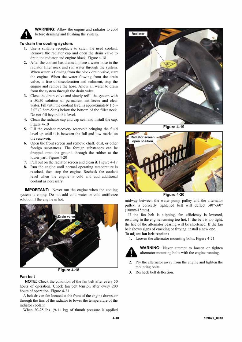
4-10 109627_0910
WARNING: Allow the engine and radiator to coolbefore draining and flushing the system.
To drain the cooling system:1. Use a suitable receptacle to catch the used coolant.
Remove the radiator cap and open the drain valve todrain the radiator and engine block. Figure 4-18
2. After the coolant has drained, place a water hose in theradiator filler neck and run water through the system.When water is flowing from the block drain valve, startthe engine. When the water flowing from the drainvalve, is free of discoloration and sediment, stop theengine and remove the hose. Allow all water to drainfrom the system through the drain valve.
3. Close the drain valve and slowly refill the system witha 50/50 solution of permanent antifreeze and clearwater. Fill until the coolant level is approximately 1.5”-2.0” (3.8cm-5cm) below the bottom of the filler neck.Do not fill beyond this level.
4. Clean the radiator cap and cap seal and install the cap.Figure 4-19
5. Fill the coolant recovery reservoir bringing the fluidlevel up until it is between the full and low marks onthe reservoir.
6. Open the front screen and remove chaff, dust, or otherforeign substances. The foreign substances can bedropped onto the ground through the rubber at thelower part. Figure 4-20
7. Pull out on the radiator screen and clean it. Figure 4-178. Run the engine until normal operating temperature is
reached, then stop the engine. Recheck the coolantlevel when the engine is cold and add additionalcoolant as necessary.
IMPORTANT: Never run the engine when the coolingsystem is empty. Do not add cold water or cold antifreezesolution if the engine is hot.
Fan beltNOTE: Check the condition of the fan belt after every 50
hours of operation. Check fan belt tension after every 200hours of operation. Figure 4-21
A belt-driven fan located at the front of the engine draws airthrough the fins of the radiator to lower the temperature of theradiator coolant.
When 20-25 lbs. (9-11 kg) of thumb pressure is applied
midway between the water pump pulley and the alternatorpulley, a correctly tightened belt will deflect .40”-.60”(10mm-15mm).
If the fan belt is slipping, fan efficiency is lowered,resulting in the engine running too hot. If the belt is too tight,the life of the alternator bearing will be shortened. If the fanbelt shows signs of cracking or fraying, install a new one.To adjust fan belt tension:
1. Loosen the alternator mounting bolts. Figure 4-21
WARNING: Never attempt to loosen or tightenalternator mounting bolts with the engine running.
2. Pry the alternator away from the engine and tighten themounting bolts.
3. Recheck belt deflection.Figure 4-18
Drain valve
Figure 4-19
Figure 4-20
Radiator
Radiator screen open position

109627_0910 4-11
Transmission, front axle and hydraulic system
WARNING: Hydraulic fluid escaping under pressuremay have sufficient force to penetrate skin and causeserious injury. Foreign fluid injected into the skin mustbe surgically removed within a few hours by a doctor,familiar with this form of injury, or gangrene mayresult. Before applying pressure to hydraulic system, makesure all connections are tight and all hoses and linesare in good condition. To find a leak under pressure,use a piece of cardboard or wood — never use yourhands. Relieve all pressure in the system before dis-connecting or working on hydraulic lines. To relievepressure, lower all attachments and shut off engine.
Checking Oil Level: Check the oil level every 50 hours.
1. With the tractor standing level and the engine off, checkthe oil level with the dipstick. Figure 4-22
2. The oil is at the correct level when the oil level is withinthe mark at the lower end of the dipstick. If low, add ISOVG46 hydraulic oil, through the filler hole. Do not fillbeyond the mark on the stick, as the transmission will beoverfilled.
3. Install the dipstick.
Changing Oil & Filters:NOTE: Replace the filters after the first 50 hours of opera-
tion and every 500 hours or annually thereafter following theprocedure below:
Change the oil every 500 hours or annually.1. With the oil at normal operating temperature, drain and
discard the oil by removing the transmission drain plug.Reinstall the plug after the oil has drained. Figure 4-23
WARNING: The oil will be hot. Use caution to pre-vent skin coming in contact with hot oil.
2. Unscrew the oil filters and discard. Figure 4-24 & Figure4-25
3. Coat the gasket on the new filters with a film of oil.
Screw the filters into place until the gasket contacts thesealing surface, then tighten the filters approximately 3/4of a turn by hand. Do not over tighten. Figure 4-24 &Figure 4-25
4. Remove the filler plug and dipstick and fill with ISOVG46 hydraulic oil.
5. The transmission is filled to the correct level when the oillevel is within the mark at the lower end of the dipstick.Do not fill beyond the mark on the stick, as thetransmission will be overfilled.
6. Install the dipstick and filler plug.7. Start the engine and check the hydraulic oil filter for
leaks.8. Stop the engine and check the hydraulic oil level.
Replenish if necessary.
IMPORTANT: The transmission, front axle and hydraulicsystem operate from a common oil sump. Special attention mustbe given to keeping oil clean.
Rear axle case and final reduction gear casesCheck the oil level every 100 hours.
1. Clean the area around the dipstick/filler plug to preventdirt from entering the rear axle housing. With the engineoff and the tractor standing level, check the oil levelusing the combined dipstick/filler plug. The oil is at thecorrect level when it reads between the two marks on thedipstick.
Figure 4-21
Alternator adjusting
bolts
Fan belt
Figure 4-22
Figure 4-23
Dipstick
Filler hole
Drain plug

4-12 109627_0910
NOTE: Place the dipstick/filler plug into the oil inlet tomeasure the oil level. Do not screw dipstick into housingwhen checking oil level. Figure 4-26
2. If the level is low, add ISO VG46 hydraulic oil throughthe filler hole. Do not fill above the dipstick full mark.
3. Reinstall the dipstick/filler plug.
Change the oil every 500 hours or annually.1. With the oil at normal operating temperature, drain the oil
by removing the rear axle and final reduction gear casedrain plugs. Reinstall the plugs after the oil has drained.Discard the oil. Figure 4-27 & Figure 4-28
2. Supply new ISO VG46 hydraulic oil into the fill holeuntil oil level is between the two marks on the dipstick.Figure 4-26
3. To fill the final reduction gear cases with new ISO VG46hydraulic oil:a. Remove the right and left rear wheels.b. Oil supply plugs are located on the front side of the
right and left final reduction gear case. Remove theplugs. Figure 4-29
c. Pour the hydraulic oil in the plug holes until the finalreduction gear cases are full
d. Re-install plugs.
PTO control lever adjustmentNOTE: Adjust the PTO control lever linkage every 100 hours.
1. The PTO control lever must move easily (soft), throughthe first 50% of travel. The remaining 50% of controllever travel must have a resistance (hard).
2. At the point of resistance (50% into the control leverstroke), attach a pull scale to the PTO control lever. Areading of 11.5 lbs (5 kg) is correct at the point of
Figure 4-24
Figure 4-25
HST oil filter
Hydraulic oil filter
Figure 4-26
Figure 4-27
Figure 4-28
Rear axle oil fill & dipstick
Rear axle oil drain
Final reduction gear case drain plug

109627_0910 4-13
resistance (50% into the control lever stroke). A readingof 26.4-28.6 lbs. (12-13 kg) is correct at the fullengagement point (the final 50% of control lever travel).If the control lever stroke is not correct, or the amount ofresistance on the pull scale at the point of resistance isincorrect, proceed to step 3.NOTE: The adjustment bolt on the PTO adjustmentlinkage uses left-hand threads.
3. Loosen the locknuts on the PTO adjustment linkage.Figure 4-30
4. Turn the adjustment rod and recheck the resistance on thepull scale and the control lever stroke. Repeat this stepuntil the control lever stroke and the pull resistance arecorrect.
5. Tighten the locknuts.
General engine maintenanceDetailed instructions and recommendations for break-in and
regular maintenance are specified in the Engine Owner’smanual. Please refer to this manual for engine servicing,lubricating oil levels with the proper SAE rating and viscosityrecommendations, bolt torques, etc. The engine warranty isbacked by the manufacturer. Special attention should be paid toapplicable data which will not be duplicated here.
Park brake adjustmentThe park brake must be adjusted when there is less than 0.38
in. (10mm) or more than 0.75 in. (19mm) of free play in thepark brake lever (Figure 4-31), the park brake is dragging, or thepark brake is not working effectively.
1. Park tractor on level ground, lower the mower deck orfront mount attachment to the ground, turn off tractor,and remove key. Chock the front drive tires to keepmachine from rolling.
2. Check the park brake lever free travel distance: With thepark brake lever all the way down (Off), pull the lever upuntil you notice resistance from brake engagement -measure this distance as shown in Figure 4-31. This freeplay distance should be 0.38 in. (10mm) to 0.75 in.(19mm).
3. To adjust the park brake free play, raise the seat platformand secure it in the up position. IMPORTANT: Make sure the seat platform is securedproperly in the up position to prevent it from falling backdown on you as you are working.
4. Loosen the jam nuts on each of the park brake cable in-line cable adjuster barrels as shown in Figure 4-32.Back the jam nuts off several turns.
5. Turn the in-line cable adjuster barrel (Figure 4-32) oneach cable accordingly to properly adjust the cable.Lengthening the in-line cable adjuster assembly(exposing more threads) will tighten the cable and reducethe free play. Shortening the in-line cable adjusterassembly length (less exposed threads) will loosen thecable and create more free play. Both cables should beadjusted so they are providing equal free play when thebrake is off, and equal brake force on each brake whenthe park brake is applied.
6. Re-check the free play (step 2). Re-adjust as necessary.7. Tighten the jam nuts.Once the park brake is adjusted properly, check to make sure
it is working effectively and does not drag. If any problemspersist, do NOT operate the tractor, and contact your dealer.
Inspecting and adjusting the service brakeThe service brake must be adjusted when:
a. There is less than 0.38 in. (10mm) or more than 0.75in. (19mm) of free travel in the brake pedal (Figure 4-33 & Figure 4-34), or,
b. When the brakes do not work effectively, or,
Figure 4-29
Figure 4-30
Final reduction gear case fill plug
Linkage
Locknuts
Figure 4-31
.38” - .75”(10 mm - 19 mm)

4-14 109627_0910
c. When the brakes are dragging.1. Park tractor on level ground, lower the mower deck or
attachment to the ground, turn off tractor and remove key.Chock the front drive tires to keep machine from rolling.Make sure the park brake is in the OFF position.
2. Check the free travel of the brake pedal (Figure 4-33 &Figure 4-34). This is determined by the distance thebrake pedal travels from its rear most position pushingforward on the pedal until you feel the brakes beginningto engage. Measure this distance - if it is more than 0.75in. (19mm) or less than 0.38 in. (10mm), the brakes mustbe adjusted.
3. The brake linkage rods are located underneath the floorpan. (Figure 4-35) Loosen the jam nuts located behindthe front clevis on each of the brake linkage rodassemblies. Back the jam nuts off. Figure 4-36
4. Adjust the brake linkage rods accordingly until theproper brake pedal free play is achieved. Make sure theright and left brake linkage rod lengths are adjustedequally.
5. Re-check the pedal free play (step 2). Re-adjust asnecessary.
6. Tighten the jam nuts against the clevis base.
Once the brakes have been properly adjusted, check to makesure they are working correctly on the tractor in a safe area awayfrom any obstructions or bystanders. Make sure the brakingforce on both front drive wheels is equal. Re-adjust ifnecessary.
If you find that the brakes are dragging, check the park brakeadjustment. If this does not fix the problem and your brakescontinue to work incorrectly, do not operate the tractor andcontact your Hustler Dealer.
Rear wheel toe adjustment1. Park the tractor on a flat, level surface with the rear
wheels oriented so the tractor will drive a straight lineforward.
2. Fully engage the park brake, lower the front endattachment, and turn off the tractor. Remove the keys.Chock the front drive tires of the tractor.
3. Measure 'F' and 'R' dimensions: The distance betweenthe inside of the rim edge of the RH wheel to the LHwheel. This measurement needs to be taken at the points
on the wheel rims horizontal with the axle center. Figure4-37
Figure 4-32
Park brake linkage
Cable adjuster barrels
Jam nut
Jam nut
Figure 4-33
Figure 4-34
Figure 4-35
Bottom edge of brake pedal
.38” - .75”(10 mm - 19 mm)
Bottom edge of brake pedal
Bottom edge of brake pedal
Brake adjusting rod - left side
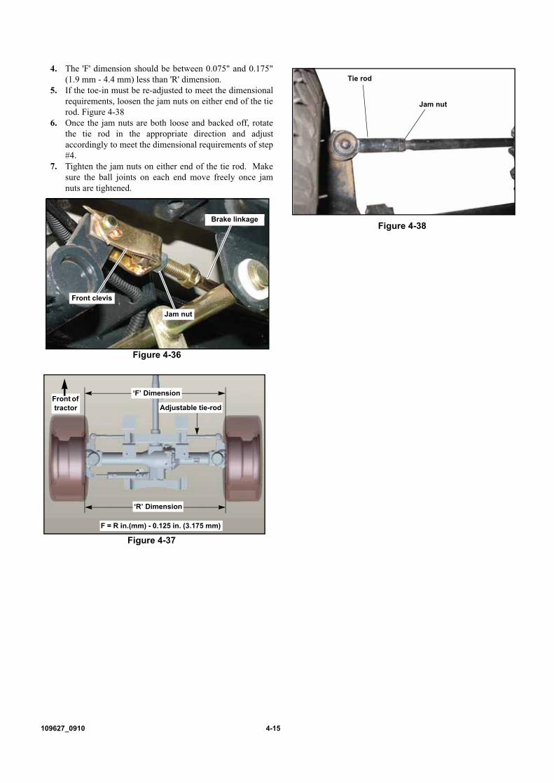
109627_0910 4-15
4. The 'F' dimension should be between 0.075" and 0.175"(1.9 mm - 4.4 mm) less than 'R' dimension.
5. If the toe-in must be re-adjusted to meet the dimensionalrequirements, loosen the jam nuts on either end of the tierod. Figure 4-38
6. Once the jam nuts are both loose and backed off, rotatethe tie rod in the appropriate direction and adjustaccordingly to meet the dimensional requirements of step#4.
7. Tighten the jam nuts on either end of the tie rod. Makesure the ball joints on each end move freely once jamnuts are tightened.
Figure 4-36
Figure 4-37
Front clevis
Jam nut
Brake linkage
‘F’ Dimension
‘R’ Dimension
F = R in.(mm) - 0.125 in. (3.175 mm)
Adjustable tie-rodFront of tractor
Figure 4-38
Jam nut
Tie rod

4-16 109627_0910

109627_0910 4-17
3500/3700 Maintenance ScheduleRefer to Figures 4-39 & 4-40
SERVICE ATINTERVALS INDICATED Daily
First 50
hours
Every 50
hours
Every 100
Hours
Every 200
hours
Every 500
hoursSeasonal
Engine oil level X
Radiator coolant level X
Radiator screen X
Visually inspect unit for loose hardware and/or damaged parts (A) X
Hydraulic filter - replace X X
HST filter - replace X X
Engine oil - replace X X
Engine oil filter - replace X
Tire pressure X
Wheel bolt torque (B) X
All fluid levels X
Tire pressure X
Battery X
Fan Belt inspection X
Transmission oil - check level X
Lift arm grease fittings - lubricate X
Lift cylinder grease fittings - lubricate X
Brake pedal shaft grease fitting - lubricate X
Power steering cylinder grease fitting - lubricate X
Differential lock pedal shaft grease fitting - lubricate X
Fuel filter - drain X
Rear axle 4WD oil - check level X
PTO control lever adjustment(Refer to PTO Control Lever Adjustment section) X
Check hydraulic hoses & fuel linesfor cracks and leaks X
Fuel filter element - replace X
Fan belt tension X
Wheel lug bolt torque X
Transmission oil & filters - replace X
Rear axle 4WD oil - replace X
Air cleaner element - replace(Refer to Engine Air Filter section) X
Radiator coolant - replace X
NOTE: A. Trash and clipping buildup around engine could cause a fire. Keep engine compartment and
muffler area clean.B. Torque wheel lug bolts to the following torques after the first 2 hours of operation.
Front wheel lug bolts 85-95 ft.-lbs. (115-129 Nm)Rear wheel lug bolts 65-75 ft.-lbs. (88.1-101.7 Nm)

4-18 109627_0910
MAINTENANCE LOCATOR CHART
2
31
54
6
67
7
9
108
18
1. Engine Oil Fill2. Engine Air Cleaner3. Radiator Cap4. HST Filter5. Hydraulic Oil Filter6. Engine Oil Filter & Dipstick7. Wheels & Tires8. Fuel Filter9. Battery
10. Fan Belt11. Transmission Oil Fill12. Lift Arm13. Lift Cylinder14. Brake Pedal Shaft15. Power Steering Cylinder16. Differential Lock Pedal Shaft17. Rear Axle 4WD Oil Fill/Dipstick18. Radiator Screen
Figure 4-39

109627_0910 4-19
17
MAINTENANCE LOCATOR CHART
11
1. Engine Oil Fill2. Engine Air Cleaner3. Radiator Cap4. HST Filter5. Hydraulic Oil Filter6. Engine Oil Filter & Dipstick7. Wheels & Tires8. Fuel Filter9. Battery
10. Fan Belt11. Transmission Oil Fill12. Lift Arm13. Lift Cylinder14. Brake Pedal Shaft15. Power Steering Cylinder16. Differential Lock Pedal Shaft17. Rear Axle 4WD Oil Fill/Dipstick18. Radiator Screen
12
14
16 15
13
13
Figure 4-40

4-20 109627_0910
109627_0910 5-1
STORAGEWhen storing the unit at the end of the operating season, the
following steps should be taken to ensure readiness for thenext season.
1. Remove all grass, dirt, and trash from tractor andmower. Clean tractor and mower and touch up allscrapes with Hustler spray paint.IMPORTANT: Wash the machine with a mild detergent andwater. Do not pressure wash the machine. Avoid excessive use ofwater
2. Install new air filter per Engine Owner’s Manual.3. Check thoroughly for any worn or damaged parts that
need replacing and order them from your dealer.4. If the tractor does not have a deck mounted, raise the
lift arms hydraulically to their fully raised position sothat the lift cylinder is fully retracted. This will protectthe cylinder rod surfaces from corrosion.
5. Lubricate the unit. Drain and refill the transmission,hydraulic system and front axle with new oil.
6. Block tractor up so weight is off tires.7. Do not deflate tires.8. Perform separate engine preparation as listed below.9. Store tractor in a clean, dry place.
10. Remove the battery from machinea. Clean batteryb. Check the electrolyte levelc. Charge the battery, if necessaryd. Store battery in a cool, dry place (do not expose to
freezing temperatures)e. Always keep the battery fully charged. (Especially
important to prevent battery damage when thetemperature is below 32oF (0oC).)
Preparation of engine for storageWhen engine is to be unused for long periods, proceed as
follows:1. Run engine for a minimum of 15 minutes.2. Drain oil from crankcase while engine is still warm.3. Refill with fresh oil of proper viscosity.4. Special precautions should be taken to protect the fuel
injection pump and injector nozzle against corrosionand gumming.
5. Flush the fuel system with a special oil, a quantity ofwhich will remain in the system when the engine isshutdown. Special diesel fuel system flushing oils areavailable from most oil companies. If this oil is not
available, mix 0.5 qts.(0.5 liters) of SAE 10 non-detergent engine oil with 2.64 gal. (10 liters) of No. 2diesel fuel. Drain the fuel tank and pour 1.85 gal. (7liters) of the special flushing oil (or lubricatingmixture) into the fuel tank. Run the engine for 10minutes to ensure complete distribution of the specialoil through the injection pump and fuel injectors. Thereis no need to remove the injector nozzles.
6. Fill the fuel tank with No. 1 diesel fuel. IMPORTANT:Do not use No. 2 diesel fuel, for winter storage,because of wax separation and setting at lowtemperature.
7. Open the drain valve on the radiator. Flush the system,close the drain valve and fill with a 50/50 solution ofpermanent antifreeze and clear water..
8. Clean exterior surface of engine. Spread a light film ofoil over any exposed metal surfaces of engine that aresubject to corrosion.
9. Clean dirt and chaff from radiator fins and muffler.10. Check oil filler cap and fuel tank cap to make certain
they are securely in place.11. Refer to engine manual for more information.
New season preparationBefore starting the tractor following post season storage,
the following servicing is required:1. Clean tractor, removing trash and dirt accumulation.2. Check engine oil level and common sump (for the
hydraulic lift, transmission, front axle and powersteering) and the rear axle.
3. Install a fully charged battery.4. Check the cooling system for proper level of 50/50
solution of anti-freeze and clear water.5. Tighten any bolts that have loosened and make sure all
hair pins, cotter pins and clevis pins are in place.6. Install all safety shields and review safety precautions
listed in this manual.7. Check and inflate tires to 14-18 psi (96-124 KPA).8. Refer to engine manual for more information.9. Start the engine and allow it to idle a few minutes. Be
sure the engine has proper oil pressure and that eachcontrol is functioning properly.
10. Drive the unit without load and check to be sure it isoperating satisfactorily.
PRODUCT LITERATUREIf you would like to view or print a copy of the Hustler 3500/3700 product manuals go online to www.hustlerturf.com and
click on the MANUALS button.

5-2 109627_0910

INDEX PAGE PAGE
109627_0910 6-1
Auxiliary valve kit (optional) . . . . . . . . . . . . . . . . . . 3-10
Children . . . . . . . . . . . . . . . . . . . . . . . . . . . . . . . . . . 3-3
Controls . . . . . . . . . . . . . . . . . . . . . . . . . . . . . . . . . . 3-4
Cooling system . . . . . . . . . . . . . . . . . . . . . . . . . . . . . 4-9
Driving the tractor . . . . . . . . . . . . . . . . . . . . . . . . . . 3-13
Electrical system . . . . . . . . . . . . . . . . . . . . . . . . . . . . 4-2
Engine air filter . . . . . . . . . . . . . . . . . . . . . . . . . . . . . 4-8
Engine oil and filter . . . . . . . . . . . . . . . . . . . . . . . . . . 4-7
Engine starting . . . . . . . . . . . . . . . . . . . . . . . . . . . . . 3-8
Fuel system . . . . . . . . . . . . . . . . . . . . . . . . . . . . . . . . 4-5
General engine maintenance . . . . . . . . . . . . . . . . . . . 4-13
Inspecting and adjusting the service brake . . . . . . . . . 4-13
Instrument Panel . . . . . . . . . . . . . . . . . . . . . . . . . . . . 3-3
International Symbols . . . . . . . . . . . . . . . . . . . . . . . . 2-5
Lubrication . . . . . . . . . . . . . . . . . . . . . . . . . . . . . . . . 4-2
Maintenance & Adjustments Introduction . . . . . . . . . . 4-1
Maintenance Schedule . . . . . . . . . . . . . . . . . . . . . . . 4-17
Manual version . . . . . . . . . . . . . . . . . . . . . . . . . . . . . 1-2
Model and serial number . . . . . . . . . . . . . . . . . . . . . . 1-1
New season preparation . . . . . . . . . . . . . . . . . . . . . . . 5-1
Operating suggestions . . . . . . . . . . . . . . . . . . . . . . . 3-13
Operating the hydrostatic transmission and PTO . . . . . . 3-9
Operation . . . . . . . . . . . . . . . . . . . . . . . . . . . . . . . . . 3-1
Park brake adjustment . . . . . . . . . . . . . . . . . . . . . . . 4-13
Preparation of engine for storage . . . . . . . . . . . . . . . . . 5-1
PTO control lever adjustment . . . . . . . . . . . . . . . . . . 4-12
Rear counter-balance weights . . . . . . . . . . . . . . . . . . 3-11
Rear wheel toe adjustment . . . . . . . . . . . . . . . . . . . . 4-14
ROPS (Roll Over Protective Structure) . . . . . . . . . . . 3-11
Safe Servicing Practices . . . . . . . . . . . . . . . . . . . . . . . 4-1
Safety and instruction decals . . . . . . . . . . . . . . . . . . . . 2-1
Safety start interlock system . . . . . . . . . . . . . . . . . . . . 3-6
Seat adjustment . . . . . . . . . . . . . . . . . . . . . . . . . . . . . 3-6
Service access . . . . . . . . . . . . . . . . . . . . . . . . . . . . . . 4-2
Slope Operation . . . . . . . . . . . . . . . . . . . . . . . . . . . . . 3-2
Steering wheel adjustment . . . . . . . . . . . . . . . . . . . . . 3-6
Stopping the engine . . . . . . . . . . . . . . . . . . . . . . . . . . 3-9
Switches . . . . . . . . . . . . . . . . . . . . . . . . . . . . . . . . . . 3-3
Tires . . . . . . . . . . . . . . . . . . . . . . . . . . . . . . . . . . . . . 4-2
To the new owner . . . . . . . . . . . . . . . . . . . . . . . . . . . . 1-1
Torque values . . . . . . . . . . . . . . . . . . . . . . . . . . . . . . 4-2
Transmission, front axle and hydraulic system . . . . . . 4-11
Using a ramp . . . . . . . . . . . . . . . . . . . . . . . . . . . . . . . 3-2
Using this manual . . . . . . . . . . . . . . . . . . . . . . . . . . . 1-1
Warranty . . . . . . . . . . . . . . . . . . . . . . . . . . . . . . . . . . 1-1

6-2 109627_0910