hub high speed electrical test procedure - usb.org · hub high speed electrical test procedure...
TRANSCRIPT

Hub High Speed Electrical Test Procedure Revision 1.4
1
Universal Serial Bus Implementers Forum
Hub High-speed Electrical Test Procedure for
Tektronix TDS7254/B, TDS7704/B, CSA7404/B, TDS6604/B,
TDS6804/B, TDS6404, DPO7254,DPO7354, and
DPO/DSA70000 series
Revision 1.4
Mar 2008

Hub High Speed Electrical Test Procedure Revision 1.4
Revision History
Rev Date Filename Comments
0.8 June-29-2001 Hub HS Test.DOC Initial draft revision
0.81 12-Jul-01 Hub HS Test.DOC Changed el_17 on page 58 to reference section 7.1.6.2
0.9 (Beta) Aug-31-2001 Hub HS Test.DOC Switch to integrated Test Tool software in place of SSTD and Test Mode software; remove redundant tests; Align test assertion section number (EL_xx) to Version 1.00 of USB-IF USB 2.0 Electrical Test Specification
1.0 Dec-23-2001 Hub HS Test.DOC Edit for final release. Delete TDR section.
1.1 November-10-2002
Hub HS Test Tektronix.DOC
Edit to add procedures to accommodate testing using the Tektronix TDS7000/6000 series oscilloscopes and TDSUSB, USB compliance test application
1.2 April 1, 2003 Hub HS Test Tektronix.doc Edit and clean up – for publication
1.3 February, 2007 Hub HS Test Tektronix.doc Changes made according to new test fixture
1.4 March 2008 Hub HS Test Tektronix.doc Updated the model numbers
Please send comments via electronic mail to [email protected]
USB-IF High-speed Electrical Test Procedure © Copyright 2001, USB Implementers Forum, Inc.
All rights reserved.
2

Hub High Speed Electrical Test Procedure Revision 1.4
3
DISCLAIMER OF WARRANTIES
THIS SPECIFICATION IS PROVIDED “AS IS” AND WITH NO WARRANTIES OF ANY KIND, EXPRESS OR IMPLIED, INCLUDING, WITHOUT LIMITATION, NO WARRANTY OF NONINFRINGEMENT, NO WARRANTY OF MERCHANTABILITY, NO WARRANTY OF FITNESS FOR A PARTICULAR PURPOSE, NO WARRANTY OF TITLE, AND NO WARRANTY ARISING OUT OF ANY PROPOSAL, SPECIFICATION, OR SAMPLE, ALL OF WHICH WARRANTIES ARE EXPRESSLY DISCLAIMED.
WITHOUT LIMITING THE GENERALITY OF THE FOREGOING, USB-IF AND THE AUTHORS OF THE SPECIFICATION DO NOT WARRANT OR REPRESENT THAT USE OF THE SPECIFICATION WILL NOT INFRINGE THE INTELLECTUAL PROPERTY RIGHTS OF OTHERS. USERS OF THE SPECIFICATIONASSUME ALL RISK OF SUCHINFRINGEMENT, AND AGREE THAT THEY WILL MAKE NO CLAIM AGAINST USB-IF OR THE AUTHORS IN THE EVENT OF CLAIMS OF INFRINGEMENT.
USB-IF IS NOT LIABLE FOR ANY CONSEQUENTIAL, SPECIAL OR OTHER DAMAGES ARISING OUT OF THE USE OF THE SPECIFICATION.
LICENSE FOR INTERNAL USE ONLY
USB-IF HEREBY GRANTS A LICENSE TO REPRODUCE AND TO DISTRIBUTE THIS SPECIFICATION FOR INTERNAL USE ONLY. NO OTHER LICENSE, EXPRESS OR IMPLIED, BY ESTOPPEL OR OTHERWISE, IS GRANTED HEREWITH, AND NO LICENSE OF INTELLECTUAL PROPERTY RIGHTS IS GRANTED HEREWITH.
All product names are trademarks, registered trademarks, or service marks of their respective owners.

Hub High Speed Electrical Test Procedure Revision 1.4
4
Table of Contents 1 Introduction ..............................................................................................................6
2 Purpose ......................................................................................................................6
3 Recommended Equipment.......................................................................................7 3.1 Equipment Setup ........................................................................................................8
3.1.1 DPO7000 and DPO/DSA70000 series oscilloscopes ......................................8 3.1.2 Digital Signal Generator..................................................................................8
3.2 Operating Systems, Software, Drivers, and Setup Files .........................................9 3.2.1 Operating Systems ...........................................................................................9
3.3 Special Purpose Software ..........................................................................................9 3.3.1 Test Equipment Setup Files ............................................................................9
3.4 Test fixture ................................................................................................................10 3.5 Test Procedure..........................................................................................................12 3.6 Test Record ...............................................................................................................12 3.7 Vendor and Product Information ...........................................................................12 3.8 Legacy USB Compliance Tests................................................................................12 3.9 Hub High-speed Signal Quality – Upstream Facing Port (EL_2, EL_46, EL_6, EL_7) ....................................................................................13 3.10 Hub High-speed Signal Quality – Downstream Facing Ports (EL_2, EL_3, EL_6, EL_7) ......................................................................................18 3.11 Hub Jitter – Downstream Facing Ports (EL_47)...................................................21 3.12 Hub Disconnect Detect (EL_36, EL_37).................................................................25 3.13 Hub Packet Parameters – Upstream Facing Port (EL_21, EL_22, EL_25)........27 3.14 Hub Receiver Sensitivity – Upstream Facing Port (EL_16, EL_17, Device Receiver Sensitivity (EL_16, EL_17, EL_18)................................33 3.15 Hub Repeater Test – Downstream Facing Ports (EL_42, EL_43, EL_44, EL_45, EL_48) .............................................................................................40 3.16 Hub Repeater Test – Upstream Facing Port (EL_42, EL_43, EL_44, EL_45) .............................................................................................43 3.17 Hub CHIRP Timing – Upstream Facing Port (EL_28, EL_29, EL_31)..............48 3.18 Hub Suspend/Resume/Reset Timing – Upstream Facing Port (EL_27, EL_28, EL_38, EL_39, EL_40) .................................................................51 3.19 Hub Test J/K, SE0_NAK – Upstream Facing Port (EL_8, EL_9) ......................56 3.20 Hub Test J/K, SE0_NAK – Downstream Facing Ports (EL_8, EL_9).................58

Hub High Speed Electrical Test Procedure Revision 1.4
5
A.1 Hub High-speed Electrical Test Data ...................................................................60 A.1.1 Vendor and Product Information ...........................................................................60 A.1.2 Legacy USB Compliance Tests................................................................................61 A.1.3 Hub High-speed Signal Quality – Upstream Facing Port (EL_2, EL_46, EL_6, EL_7) ....................................................................................61 A.1.4 Hub High-speed Signal Quality – Downstream Facing Ports (EL_2, EL_3, EL_6, EL_7) ......................................................................................62 A.1.5 Hub Jitter – Downstream Facing Ports (EL_47) ...................................................64 A.1.6 Hub Disconnect Detect (EL_36, EL37) ...................................................................65 A.1.7 Hub Packet Parameters – Upstream Facing Port (EL_21, EL_22, EL_25) ........66 A.1.8 Hub Receiver Sensitivity – Upstream Facing Port (EL_16, EL_17, EL_18) ......67 A.1.9 Hub Repeater Test – Downstream Facing Ports (EL_42, EL_43, EL_44, EL_45, EL_48) ...........................................................................................68 A.1.10 Hub Repeater Test – Upstream Facing Port (EL_42, EL_43, EL_44, EL_45).............................................................................69 A.1.11 Hub CHIRP Timing – Upstream Facing Port (EL_28, EL_29, EL_31) ............70 A.1.12 Hub Suspend/Resume/Reset Timing – Upstream Facing Port (EL_27, EL_28, EL_38, EL_39, EL_40) ..............................................................71 A.1.13 Hub Test J/K, SE0_NAK - Upstream Facing Port (EL_8, EL_9) ......................73 A.1.14 Hub Test J/K, SE0_NAK – Downstream Facing Ports (EL_8, EL_9) ...............74

Hub High Speed Electrical Test Procedure Revision 1.4
6
1 Introduction The USB 2.0 Compliance Committee under the direction of USB-IF, Inc. develops the USB-IF High-speed Electrical Test Procedures. There are three High-speed Electrical Test Procedures.
• The Host High-speed Electrical Test Procedure is for EHCI host controllers.
• The Hub High-speed Electrical Test Procedure is for high-speed capable hubs.
• The Device High-speed Electrical Test Procedure is for high-speed capable devices.
The High-speed Electrical Compliance Test Procedures verify that the electrical requirements of high-speed USB operation of these devices designed to the USB 2.0 specification. In addition to passing the high-speed test requirements, high-speed capable products must also complete and pass the applicable legacy compliance tests identified in these documents in order to be posted on the USB-IF Integrators List and use the USB-IF logo along with the said product (if the vendor has signed the USB-IF Trademark License Agreement). These legacy compliance tests are identified in the Legacy USB Compliance Test section in this document.
This test procedure is an update of the USB-IF Host Electrical High-speed Test Procedure written for the Tektronix TDS694C and the USB-IF MATLAB scripts. This updated procedure is written to support Tektronix TDS7404/B, CSA7404/B, TDS7704B, TDS7254/B, TDS6604/B, TDS6804/B, TDS6404, DPO7254, DPO7354 and DPO/DSA70000 series running TDSUSB2 Compliance Test Application Software. The TDSUSB2 software is used in place of the MATLAB scripts and NI GPIB DAQ software.
2 Purpose This USB-IF High-speed Electrical Test Procedure documents a series of tests used to evaluate USB peripherals and systems operating at high speeds. These tests are also used to evaluate the high-speed operation of USB silicon that has been incorporated in ready-to-ship products, reference designs, proofs of concept and one of a kind prototypes of peripherals, add-in cards, motherboards, or systems.
This test procedure refers to the test assertions in the USB-IF USB2.0 Electrical Test Specification, Version 1.3.
This Hub High-speed Electrical Test Procedure is one of the three USB-IF High-speed Electrical Compliance Test Procedures. The other two are Host High-speed Electrical Test Procedure and Device High-speed Electrical Test Procedure. The adoption of the individual procedures based on the device class makes it easier to use.

Hub High Speed Electrical Test Procedure Revision 1.4
7
3 Recommended Equipment The commercial test equipment listed here are based on positive experience by the USB-IF members in executing the USB high-speed electrical tests. This test procedure is written with a set of specific models we use to develop this procedure. In time, there will be other equivalent or better test equipment suitable for use. Some minor adaptation of the procedure will be required in those cases.
• Digital Sampling Oscilloscope:
• A DPO7254, DPO7354, TDS7254/B, TDS7404/B or CSA7404/B or TDS7704B, or greater bandwidth oscilloscope is required to test the high-speed USB hosts, devices, or hubs
• A DPO7054 or TDS5034B or greater bandwidth oscilloscope is required to test low-speed and full-speed USB devices and hubs
• A P6330 or P6248 1.7 GHz differential probe or greater bandwidth probe. For example, P63301, P7330, P7360, P7380, qty = 2
• Tektronix TAP1500 or P6245 FET probes, qty = 2
• Tektronix TAP-BNC or TCA BNC adapters, qty = 4
• TDS7000 Deskew Fixture, part number: 067-0405-xx, shipped as a standard accessory to the oscilloscope
• 3 ½ Digital Multimeter – Fluke Model 77 or equivalent
Mini-clip DMM lead – one each of black and red
• Digital Signal Generator
• Tektronix DTG5334 or DTG5274 or DTG5078 with a DTGM21 Output module; or the AWG 5000 series (AWG5002) or AWG7000 series
o 5x attenuator – for scaling the DG2040 output voltages for receiver sensitivity test, qty = 2
o 50-ohm coaxial cable with female SMA connectors at both ends, qty = 4
• High-speed USB Electrical Test Fixtures
• Tektronix TDSUSBF test fixture, qty = 1
• Disconnect test fixture, qty = 1 (source USBIF)
• Female Serial B to female Serial A adapter, qty = 1
• 6-INCH AB Cable with USB-IF compliance logo tag, qty =1
• Miscellaneous Cables
1M USB cable, qty = 5
• High-speed USB Test Bed Computer
This is the computer that hosts a USB 2.0 compliance host controller for high-speed hub or device electrical test, or serves as a test bed host for a USB 2.0 host controller under test. The OS on this computer is Windows 2000 or XP Professional. Please refer to the High-speed Electrical Test Setup Instruction for steps to configure this computer.

Hub High Speed Electrical Test Procedure Revision 1.4
8
Note: The Tektronix USB compliance test software operates internally to the oscilloscope and automatically configures the oscilloscope settings and so external GPIB control of the oscilloscope is not required.
3.1 Equipment Setup
3.1.1 DPO7000 and DPO/DSA70000 series oscilloscopes
Before turning on the oscilloscope, attach a P6247 or P6248 differential probes to Channel 1 and Channel 4. TPA-BNC adaptors are required for the DPO7000 series. Attach two P6245 FET probes, one to Channel 2 and one to Channel 3. The probe assignment will be used throughout the test procedure. Turn on the oscilloscope to allow for 10 minutes of warm up time prior to use. Perform the signal path compensation procedure built into the oscilloscope (in the Utility menu) if the ambient temperature has changed more than 5 degrees. The compensation should be performed with the probes disconnected from the oscilloscope.
The two single-end FET probes must be calibrated to minimize gain and offset errors. The offset errors of the differential probes should be cancelled using the Deskew utility of the TDSUSB software. From the TDSUSB application, select Utilities> Deskew. Follow the procedure in the applications Online Help.
For P6248 differential probes, the following setting will be used through out the entire test procedure:
Attenuation <÷1>
The use of a Tip Saver accessory on the P6248 probe is highly recommended to prolong probe tip life. Please note that the Tip Saver will wear out after repeated use and start degrading signal quality measurements. Replace the Tip Saver when measurements made without it provide better results.
Note: In certain test situation, there may not be a ground connection between the DSO and the device under test. This may lead to the signal seen by the differential probe to be modulated up and down due to mid frequency switching power supply. Connecting the DSO ground to the DUT ground will be required to establish a common ground reference.
3.1.2 Digital Signal Generator
The DSG (for example, Tektronix DTG5334, DTG5274 or DTG5078 with a DTGM21 output module; or the AWG 5000 series or AWG7000 series) is needed to perform the receiver sensitivity test that is structured toward the end of this test procedure. For energy conservation consideration, one may choose to turn on the signal generator about 15 minutes prior to performing the measurement.

Hub High Speed Electrical Test Procedure Revision 1.4
9
3.2 Operating Systems, Software, Drivers, and Setup Files
3.2.1 Operating Systems
Microsoft Windows 2000 or XP Professional is required on the High-speed Electrical Test Bed Computer. Please refer to the High-speed Electrical Test Setup Instruction for steps to configure this computer.
3.3 Special Purpose Software The following special purpose software is required. Please refer to the High-speed Electrical Test Setup Instruction for steps to configure this computer.
• High-speed Electrical Test Tool Software – To be used in the High-speed Electrical Test Bed Computer.
• Proprietary EHCI Driver Stack –The High-speed Electrical Test Tool software requires the use of a proprietary EHCI driver stack. The use of this proprietary EHCI driver stack facilitates the electrical testing that requires direct control of the command registers of the USB EHCI host controllers. The end result is a much more robust test bed environment. Since the proprietary EHCI driver stack is designed for debug and test validation, this driver stack does not support the normal functionality as found in the EHCI drivers from Microsoft (or the device vendor). An automatic driver stack switching function has been implemented into the High-speed Electrical Test Tool for easy switching between the proprietary EHCI driver stack and that from Microsoft. Upon invoking the HS Electrical Test Tool software, the driver stack will automatically switch to the Intel proprietary EHCI driver stack. Upon exiting the HS Electrical Test Tool software, the driver stack will automatically switch to the Microsoft EHCI driver stack.
• TDSUSB2 – Tektronix USB2.0 Compliance Test Software Application
3.3.1 Test Equipment Setup Files
Instrument Setup files are available for legacy Tektronix oscilloscopes and signal generators. HS_TDS6K_7Kscope_setups.zip – Contain setup files for the Tektronix TDS7404 or TDS7254 DSO (Digital Phosphor Oscilloscope). These setup files augment the TDSUSB Compliance Test Application. These setup files are used for the following tests:
• Packet Parameters (EL_21, EL_22, EL_25)
• Device Suspend/Resume/Reset timing (EL_27, EL_28, EL_38, EL_39, EL_40)
This file may be downloaded from www.tek.com using the software finder utility.
DG2040.zip – Contain setup files for Tektronix DG2040 DPG (Digital Pattern Generator) and is included with TDSUSB software distribution.

Hub High Speed Electrical Test Procedure Revision 1.4
10
3.4 Test fixture The table matches the pins of the two most recent versions of TDSUSBF test fixtures. This procedure document is based on using the pin locations of the “New Fixture” shown in the following table.
Section Old Fixture New Fixture
J36 J310
- J31
Device SQ section J34 J34
Adjacent Trigger section J13 J11
J38 J35
J29 J25
J31 J27
Device Receiver Test
J30 J24

Hub High Speed Electrical Test Procedure Revision 1.4
Figure 1: Tektronix New TDSUSBF Test Fixture
11

Hub High Speed Electrical Test Procedure Revision 1.4
12
3.5 Test Procedure
3.6 Test Record Appendix A contains the test result entry form for this test procedure. Please make copies of the Appendix A for use as test record documentation for compliance test submission. All fields must be filled in. Fields not applicable for the device under test should be indicated as N/A, with appropriate note explaining the reason. The completed test result shall be retained for the compliance test submission.
In addition to the hardcopy test record, the electronic files from the signal quality, power delivery (inrush, drop and droop), and TDR shall be retained for compliance test submission.
3.7 Vendor and Product Information Collect the following information and enter into a copy of the test record in Appendix A before performing any tests.
• Test date
• Vendor name
• Vendor address and phone, and the contact name
• Test submission ID number
• Product name
• Product model and revision
• USB silicon vendor name
• USB silicon model
• USB silicon part marking
• USB silicon stepping
• Test conducted by
3.8 Legacy USB Compliance Tests In addition to the high-speed electrical tests prescribed in this document, the hub under test must also pass the following legacy compliance tests applicable to the high-speed hub:
• Low speed signal quality – Downstream facing ports only
• Full speed signal quality – Upstream and downstream facing ports
• Inrush current – Upstream facing port only
• Drop/Droop – Downstream facing ports
• Back-drive voltage
• Interoperability

Hub High Speed Electrical Test Procedure Revision 1.4
Perform all these tests and record the measurements and summarize the Pass/Fail status in Appendix A.
3.9 Hub High-speed Signal Quality – Upstream Facing Port (EL_2, EL_46, EL_6, EL_7) This test is applicable only for the upstream facing port of the hub.
Note: Please take care in determining if the device under test incorporates a captive cable, or if it has a normal series B or mini-B receptacle. The former requires the signal quality measurement to be made at the far end. The latter requires the measurement to be made at the near end.
Turn on the oscilloscope if you have not already done so. Allow about 20 minutes for warm up.
1. Launch the TDSUSB software application on the Tektronix oscilloscope by selecting with a mouse or touch screen.
2. Press the Default Setup on the oscilloscope front panel.
3. In the applications menu bar select, File> Recall Default.
4. Within the Measurements: Select menu of the USB2.0 compliance test application, select the High Speed tab.
5. Within the Signal Quality area of the application, select the High Speed Signal Quality tests> Eye Diagram, Signal Rate, Rise time, Fall Time and EOP Width.
Note: The Monotonic Property test is available but not required as it may generate false failures due to slight variations in the signal edge due to high frequency noise and/or oscilloscope quantization error.
Figure 2: Tektronix TDSUSB Software
6. Enter a device ID (for example, TIDxxxxxxx) into the device ID dialog box and a device description into the device description dialog box.
7. Press the Configure button on the application screen. Select upstream and far end for devices with captive cables or near end for devices without a captive cable.
13

Hub High Speed Electrical Test Procedure Revision 1.4
8. Press the button. Verify that the oscilloscope display is NOT reporting “clipping”. If it is, adjust the vertical amplitude until the “clipping” message does not appear. Do not press OK on the screen until the correct waveform is displayed.
9. Attach the USB cable to the designated power supply port of the compliance test fixture.
10. Verify that the red Power LED next to J35 and the red Init LED are lit which is located on the opposite side of the Tektronix test fixture.
11. Connect the short USB cable dongle of the Device SQ segment of the test fixture into the upstream facing port of the device under test. Connect the Init port of the test fixture to a high-speed capable port of the Test Bed Computer. Apply power to the device. Place the S6 switch in INIT position and verify that the corresponding LED is lit.
12. Attach the differential probe to J310 of the test fixture. Ensure the + polarity on the probe lines up with D+ on the fixture.
13. Invoke the High-speed Electrical Test Tool software on the High-speed Electrical Test Bed computer. The main menu appears and shows the USB2.0 host controller
Figure 3: High-speed Electrical Test Tool – Main Menu
14

Hub High Speed Electrical Test Procedure Revision 1.4
14. Select Hub and click the TEST button to enter the HS Electrical Test Tool – Hub Test menu. The hub under test should be enumerated with the hub’s VID shown together with the USB address.
Figure 4: High-speed Electrical Test Tool – Hub Test Menu
15. Select TEST_PACKET from the Hub Command dropdown menu and click EXECUTE. This forces the hub under test to continuously transmit test packets.
Figure 5: Hub Upstream TEST_PACKET
16. Place the Test Switch (S6) in the TEST position. Verify that the red TEST LED is lit.
17. Using the oscilloscope, verify that the test packets are being transmitted from the port under test. Adjust the trigger level as necessary. If a steady trigger cannot be obtained by adjusting the trigger level, try a slight change to the trigger hold off.
15

Hub High Speed Electrical Test Procedure Revision 1.4
18. Once the test packet is displayed properly, press OK in the application dialog box.
19. The Tektronix USB application generally triggers and displays the correct test packet without the need to place cursors. Should cursors be required they may be enabled by selecting within the application, File> Preferences> Advanced and clicking the optional Packet Identification by user using Cursors.
20. If cursors measurement is enabled (see step 17), on the oscilloscope place the two vertical cursors around one test packet, (about one bit time) before the sync field and the other cursor just (about one bit time) after the EOP (END OF PACKET). Refer to the following figure. Press OK on the USB2 application dialog box to begin acquisition and analysis of the test packet.
Figure 6: Test Packet from Device
21. Verify that the Signal Eye, EOP Width, Rise and Fall time and Signaling Rate all pass.
The results displayed on the oscilloscope display may also be recorded to an HTML report located on the oscilloscope hard drive at the following path: C:\TekApplications\tdsusb2\report\ using the Report Generator also located within the Utilities menu.
Note: It may be necessary to modify the preset threshold levels in the configuration menu for rise and fall time or monotoncity tests to accommodate noise on the test packet. The default is 15% to 20%. For noisy signals, threshold levels set 20% to 80% is acceptable to eliminate false triggering.
16

Hub High Speed Electrical Test Procedure Revision 1.4
Figure 7: High-speed Near End SQ Eye Diagram
Figure 8: High-speed SQ HTML Report
17

Hub High Speed Electrical Test Procedure Revision 1.4
22. Save all the report files created during the tests. The report contains the test result in EL_2, EL_4 or EL_5, EL_6 and EL_7.
Note: EL_4 and EL_5 requirements are mutually exclusive. If EL_4 is tested then EL_5 is not applicable, and vice versa.
23. Return the Test switch (S6) of the test fixture back to the Normal position and verify that the Red TEST LED is not lit. Cycle power on the device in preparation for subsequent tests.
3.10 Hub High-speed Signal Quality – Downstream Facing Ports (EL_2, EL_3, EL_6, EL_7) This section applies only to the downstream facing ports of the hub under test.
1. Attach the USB cable to the designated power supply port of the Host High-speed Signal Quality test fixture.
2. Attach the differential probe to J710 (Downstream SQ section) of the test fixture. Ensure the + polarity on the probe lines up with D+ on the fixture.
3. Connect the upstream port of the hub to a high-speed root port of the test bed computer.
4. Connect the test fixture corresponding to the Host High-speed Signal Quality into the down stream facing port under test of the hub.
5. Apply power to the hub.
6. Click the Enumerate Bus button once. The hub under test should be enumerated with the hub’s VID shown together with the USB address.
7. Select TEST_PACKET from the Port Control dropdown menu. Enter the port number of the hub port being tested and click EXECUTE. This forces the hub port under test to continuously transmit test packets.
Figure 9: Hub Downstream TEST_PACKET
8. Within the Signal Quality area of the application, select the High Speed Signal Quality tests> Eye Diagram, Signal Rate, Rise time, Fall Time and EOP Width.
18

Hub High Speed Electrical Test Procedure Revision 1.4
9. Go to “Configure” select “Down Stream” “Near End”. From Source panel select Source
channel and then press icon button. Verify that the oscilloscope display is NOT reporting “clipping”. If it is, adjust the vertical amplitude until the “clipping” message does not appear. Do not press OK to the dialog pop up yet.
10. Using the oscilloscope, verify that the test packets are being transmitted from the port under test. Adjust the trigger level as necessary. If a steady trigger cannot be obtained by adjusting the trigger level, try a slight change on the trigger hold off.
11. Press OK from the application.
Note: The Tektronix USB application generally triggers and displays the correct test packet without the need to place cursors. Should cursors be required they may be enabled by selecting within the application, File> Preferences> Advanced and clicking the optional Packet Identification by User using Cursors.
12. If cursors measurement is enabled (see step 17), on the oscilloscope place the two vertical cursors around one test packet, one just (about one bit time) before the sync field and the other just (about one bit time) after the EOP (END OF PACKET). Refer to the following figure. Press OK on the USB2 application dialog box to begin acquisition and analysis of the test packet.
Figure 10: Test Packet from Device
19

Hub High Speed Electrical Test Procedure Revision 1.4
13. Verify that the Signal Eye, EOP Width, Rise and Fall Time and Signal Rate all pass. The results displayed on oscilloscope display may also recorded to an HTML report located on the oscilloscope hard drive at the following path: C:\TekApplications\tdsusb2\report\
Figure 11: High-speed Near End SQ Eye Diagram
Figure 12: HS Eye Diagram HTML Report
20

Hub High Speed Electrical Test Procedure Revision 1.4
14. Repeat steps 7 through 13 for all remaining ports.
15. Save all files created during the tests. Cycle power on the hub under in preparation for subsequent tests.
Note: A specific port fails to enter TEST_PACKET mode after TEST_PACKET command has been issued to the hub a number of times. Cycle power on the hub and click Enumerate Bus will alleviate this problem.
3.11 Hub Jitter – Downstream Facing Ports (EL_47) This section applies only to the downstream facing ports of the hub under test.
1. Attach the USB cable to the designated power supply port of the test fixture. Set the Test switch of the test fixture to the INIT position. Verify that the red POWER LED (besides J35) and the red INIT LED (corresponding to Test Position) are both lit.
2. Attach the differential probe to J710 of the test fixture. Ensure the + polarity on the probe lines up with D+ on the fixture.
3. Select High Speed from application and select the all the tests in the Signal Quality section.
Press Configure and select downstream, near end, and (input) channel. Press button. Do not press Ok now.
4. Connect the upstream port to a known good high-speed root port of the test bed computer using a 4-inch USB cable. Click the Enumerate Bus button once on the HSET. The hub under test should be enumerated with the hub’s VID shown together with the USB address.
5. Connect the Test port of the Host High-speed Signal Quality section of test fixture into the downstream facing port under test of the hub.
Note: The known good high-speed root port should have excellent signal quality eye and minimum clock jitter. A host controller with poor eye quality or clock jitter will tend to negatively affect the result of the hub under test.
6. Select TEST_FORCE_ENABLE from the Port Control dropdown menu. Enter the port number of the hub port being tested and click EXECUTE once to force-enable the hub port under test.
Figure 13: Force-Enable Hub Downstream Port
21

Hub High Speed Electrical Test Procedure Revision 1.4
7. Select PARENT TEST_PACKET from the Hub Command dropdown menu and click EXECUTE. This forces the parent port in which the hub is connected to continuously output test packets. The hub port under test repeats these test packets and is ready for signal quality and jitter tests.
Figure 14: Placing Parent in TEST_PACKET
8. Using the oscilloscope, verify that the test packets are being transmitted from the hub port under test. Adjust the trigger level as necessary.
9. Once the test packet is displayed properly, press OK in the application dialog box.
10. The Tektronix USB application generally triggers and displays the correct test packet without the need to place cursors. Should cursors be required they may be enabled by selecting within the application, File> Preferences> Advanced and clicking the optional Packet Identification by user using Cursors.
11. If cursors measurement is enabled (see step 17), place the two vertical cursors around one test packet, one just (about one bit time) before the sync field and the other just (about one bit time) after the EOP (END OF PACKET). Refer to the following figure. Press OK on the USB2 application dialog box to begin acquisition and analysis of the test packet.
22

Hub High Speed Electrical Test Procedure Revision 1.4
Figure 15: Test Packet from Device
Note: Due to the device under test, occasionally, the oscilloscope will trigger on the end of a previous test pack as shown above. You can try reacquiring the test packet or select cursor control to identify the test packet using the cursor packet identification feature of the TDSUSB application – File> Preferences > Advanced. Turn on cursors and locate the test packet to be evaluated.
12. Verify that the Signal Eye, EOP Width, Rise and Fall Time and Signaling Rate all pass. The results displayed on oscilloscope display may also record to an HTML report located on the oscilloscope hard drive at the following path: C:\TekApplications\tdsusb2\report\.
23

Hub High Speed Electrical Test Procedure Revision 1.4
Figure 16: High-speed Near End Eye Diagram
Figure 17: High-speed HTML Report
13. Save all files created during the tests. Record the test results in EL_47.
14. Repeat step 4 through step 13 for all remaining ports.
15. Save all files created during the tests. Cycle power on the hub under test in preparation for the subsequent test.
24

Hub High Speed Electrical Test Procedure Revision 1.4
3.12 Hub Disconnect Detect (EL_36, EL_37) Please note that the Disconnect Detect tests in this section apply only to downstream facing ports of the hub.
Note: This section uses the Disconnect test fixture to verify that the disconnect thresholds of the port under test by simulating the disconnect condition. The Tektronix Compliance Test Fixture does not support this test. Please enquire with the USB-IF to acquire this fixture.
When the TEST switch on the test fixture is in the position, the port under test is subjected to a threshold < 525 mV. The port should not detect a disconnection.
When the TEST Switch is in the Normal position, the port under test is subjected to a threshold > 625 mV. The port should detect a disconnection.
1. Attach the USB cable to the designated power supply to the Disconnect test fixture (J8).
2. Attach the differential probe to J7 of the test fixture. Ensure the + tip on probe lines up with D+ on the fixture. Recall the DISCDETE.SET oscilloscope setup.
3. Set the TEST switch to the Test position. Verify that the green Power LED (D1) is lit, and the yellow Test LED (D2) is also lit. This sets the test fixture to emulate a must-not-disconnect threshold.
4. Cycle power on the hub under test. Click Enumerate Bus once and verify that the hub successfully enumerates. Attach the Test port of the test fixture to the port under test. In the HS Electrical Test Tool – Hub Test menu select TEST_FORCE_ENABLE from the Port Control window. Enter the port number, click Execute once and ensure the operation is successful in the Status Window.
Figure 18: Force-Enable Hub Downstream Port
25

Hub High Speed Electrical Test Procedure Revision 1.4
5. Click the Disconnect Notify check box to monitor the disconnect status in the Status Window.
Figure 19: Enable Disconnect Notify
6. Using the oscilloscope, verify that the SOF packets are being transmitted from the port under test. The differential amplitude should be less than +/- 525 mV. Verify that the Status Window does not display Disconnect Event Detected. Record the pass/fail result in EL_37.
7. Set the TEST switch of the Disconnect test fixture to the Normal position and verify that the yellow TEST LED (D2) is not lit.
8. Using the oscilloscope monitor the differential amplitude of the SOF. It should be greater than +/- 625 mV. Verify that the Status Window now displays the Disconnect Event Detected. Record the pass/fail result in EL_36.
Figure 20: Disconnect Event Detected
9. Return the TEST switch on the fixture back to the TEST position and verify that the yellow TEST LED (D2) is lit.
10. Repeat steps 4 through 9 for all the remaining ports.
11. Remove the Disconnect test fixture from the port under test before proceeding.
26

Hub High Speed Electrical Test Procedure Revision 1.4
3.13 Hub Packet Parameters – Upstream Facing Port (EL_21, EL_22, EL_25) 1. Connect the Init port of the Device Signal Quality test fixture into a high-speed capable port of
the test bed computer.
2. Connect the Device Signal Quality Section of the test fixture (Test Port) into B receptacle of the upstream facing port under test of the hub. Apply power to the hub.
Note: The use of the Device High-speed Signal Quality section of the test fixture makes it possible to trigger on packets generated by the device because the differential probe is located closer to the device transmitter, hence the device packets are larger in amplitude.
3. Attach the channel 1 differential probe to J310 on the fixture near the device connector. Ensure the + polarity on the probe lines up with D+ on the fixture.
4. Exit the HS Electrical Test Tool – Hub Test menu by clicking Return to Main.
5. From the HS Electrical Test Tool main menu select Device and click TEST to enter the Device Test menu.
Figure 21: HS Electrical Test Tool Main Menu
27

Hub High Speed Electrical Test Procedure Revision 1.4
6. The HS Electrical Test Tool – Device Test menu should appear as in the following figure:
Figure 22: HS Electrical Test Tool – Device Test Menu
7. Select Packet Parameter measurement from the High-Speed tab and configure the device for EL_21, EL_22, and EL_25. Run the measurement.
Figure 23: Device Packet Parameter
8. Using the oscilloscope, verify that the SOFs (Start Of Frame) packets are being transmitted on the port under test.
28
Hub High Speed Electrical Test Procedure Revision 1.4
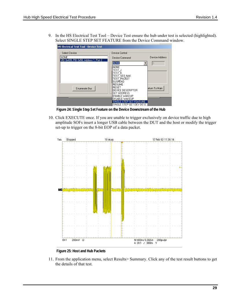
9. In the HS Electrical Test Tool – Device Test ensure the hub under test is selected (highlighted). Select SINGLE STEP SET FEATURE from the Device Command window.
Figure 24: Single Step Set Feature on the Device Downstream of the Hub
10. Click EXECUTE once. If you are unable to trigger exclusively on device traffic due to high amplitude SOFs insert a longer USB cable between the DUT and the host or modify the trigger set-up to trigger on the 8-bit EOP of a data packet.
Figure 25: Host and Hub Packets
11. From the application menu, select Results> Summary. Click any of the test result buttons to get the details of that test.
29

Hub High Speed Electrical Test Procedure Revision 1.4
12. The result contains EL_21 sync field length (number of bits) of the third (from the hub) packet on the oscilloscope and it should be of 32 bits. Refer to the following figure. Note that the Sync Field starts from the high-speed idle transitions to a falling edge (due to the first zero).
Figure 26: Sync Field Width – Upstream Packet
30

Hub High Speed Electrical Test Procedure Revision 1.4
13. The results consist of EL_25 EOP (End of Packet) width (number of bits) of the third packet on the oscilloscope.
Note: EOP could appear as a negative going pulse, or a positive going pulse on differential measurements. The figure below illustrates the appearance of a negative going EOP.
Figure 27: EOP Width – Upstream Packet
31

Hub High Speed Electrical Test Procedure Revision 1.4
14. The results consist of EL_22 inter-packet gap between the second (from host) and the third (from Hub in response to the host’s) packets are shown on the oscilloscope. The second (of lower amplitude) is from the host and third (of higher amplitude) is a hub’s response.
Figure 28: Inter-Packet Gap – Transmit after Receive
15. Select Packet Parameter measurement from the High-Speed tab, and configure for device EL_22, and run the measurement.
16. Ensure the oscilloscope is armed. In the HS Electrical Test Tool - Device Test menu, click Step once. This is the second step of the two-step Single Step Set Feature command.
Figure 29: Step Button of the SINGLE STEP SET FEATURE
32

Hub High Speed Electrical Test Procedure Revision 1.4
17. The captured oscilloscope acquisition should appear as follows.
Figure 30: Hub Packet Following Host Packet
18. The results consist of EL_22 inter-packet gap between the first (from host) and the second (from hub in respond to the host’s) packets shown on the oscilloscope. The first (of lower amplitude) is from the host and the second (of higher amplitude) is a hub’s response.
19. Exit the HS Electrical Test Tool – Device Test menu by clicking Return to Main.
20. From the HS Electrical Test Tool main menu select Hub and click TEST to enter the Hub Test menu.
3.14 Hub Receiver Sensitivity – Upstream Facing Port (EL_16, EL_17, Device Receiver Sensitivity (EL_16, EL_17, EL_18) This section tests the sensitivity of the receivers on a device under test. A Tektronix DTG5000 series instrument with DTGM21, AWG700 series, or DG2040 Data Generator emulates the In command from the hub port to device address 1.
1. Attach the USB cable to the designated power supply to the test fixture J35 and verify that the red Power LED is lit. Leave the TEST switch at the INIT position. The red test LED should be off and the red INIT LED should be on.
2. Connect the Init port of the fixture to a port on the Test Bed Computer. Connect the Test Port of the fixture to the device under test. Click the Enumerate Bus button once to force enumeration of the newly connected device. The device under test should be enumerated with the device’s VID shown together with the root port to which it is connected.
33

Hub High Speed Electrical Test Procedure Revision 1.4
3. Connect the Tektronix signal generator to the Device REC test section of the fixture using the SMA cables. Two sets of SMA cables are required, each with a 5x attenuators inserted. Connect CH 1 to SMA1, and CH 0 to SMA2, J24 and J27. The DG2040 and the AWG700 series can be equipped with 5x attenuators for higher resolution of the amplitude adjustments.
4. Connect the differential probe to the test fixture at J25. From the TDSUSB application, select Measurement> Select. Click on the High Speed tab and click Receiver Sensitivity.
5. On the Tektronix signal generator, select the Edit menu. Then press Load Data & Setup from the File function. The content of the floppy disk will appear on the screen. Use the jog dial to select the MIN-ADD1.PDA setup file. Press OK to load it. This generates IN packets (of compliant amplitude) with a 12-bit SYNC field.
6. Start the data generator output with the START/STOP button.
7. On the HS Electrical Test Tool - Device Test menu, select TEST_SE0_NAK from the Device Command dropdown menu. Click on EXECUTE button once to place the device into TEST_SE0_NAK test mode.
Figure 31: Device TEST_SE0_NAK
8. Place the test fixture Test Switch S6 into the TEST position. This switches on the data generator in place of the host controller. The Tektronix signal generator emulates the IN packets from the host controller.
34

Hub High Speed Electrical Test Procedure Revision 1.4
9. Verify that all packets from the Tektronix signal generator are NAK’d by the port under test as in the following figure. Record the Pass/Fail in EL_18.
Figure 32: Receiver Respond with NAK to IN from Data Generator
10. On the Tektronix signal generator select the Edit menu, then press Load Data & Setup from the File function. The content of the floppy disk will appear on the screen. Use the jog dial to select the IN-ADD1.PDA setup file. Press OK to load it.
11. Verify that all packets are NAK’d while signaling is at this amplitude.
12. Adjust the output level of each channel as follows:
13. Select the Setup menu. Press High from the Level Condition function. Adjustment of the output level is best done with the keypad in 50 mV while monitoring the actual level on the oscilloscope. Use the up and down arrow buttons to select the channel to change.
14. Reduce the amplitude of the Tektronix signal generator packets in 50 mV steps (on the generator before the attenuator) while monitoring the NAK response from the device on the oscilloscope. The adjustment should be made to both channels such that Channel 0 and Channel 1 are matched, as indicated by the Tektronix signal generator readout. Reduce the amplitude until the NAK packets begin to become intermittent. At this point, increase the amplitude such that the NAK packet is not intermittent. This is just above the minimum receiver sensitivity levels before squelch.
35

Hub High Speed Electrical Test Procedure Revision 1.4
15. Measure the Zero to Positive Peak of the packet from the Tektronix signal generator as in the following figure using the cursors. The peak should be taken at the plateaus of the wider pulses to avoid inflated reading due to overshoots. Press the record button on the TDSUSB application corresponding to the receiver sensitivity level and record the measurement in EL_17 of Appendix A.
Figure 33: Measuring Differential Voltage Level – Zero to Positive Peak
36

Hub High Speed Electrical Test Procedure Revision 1.4
16. Ensure the Zero to Negative Peak of the packet from the Tektronix signal generator (as in the following figure) using the cursors. The peak should be taken at the plateaus of the wider pulses to avoid inflated reading due to overshoots. Record the measurement in EL_17. As long as the receiver continues to NAK the Tektronix signal generator packet above +/- 150 mV, it is considered to pass the test. Record PASS/FAIL in EL_17.
Figure 34: Measuring Differential Voltage Level – Zero to Negative Peak
17. Now further reduce the amplitude of the packet from the data generator in small steps, still maintaining balance between Channel 0 and Channel 1 until the receiver just ceases to respond with NAK. This is the squelch level of the receiver.
37

Hub High Speed Electrical Test Procedure Revision 1.4
18. Measure the Zero to Positive Peak of the packet from the Tektronix signal generator (as in the following figure) using the cursors. The peak should be taken at the plateaus of the wider pulses to avoid inflated reading due to overshoots. Record the measurement in EL_16.
Figure 35: Measuring Differential Voltage Level – Zero to Positive Peak
38

Hub High Speed Electrical Test Procedure Revision 1.4
19. Measure the Zero to Negative Peak of the packet from the Tektronix signal generator (as in the following figure) using the cursors. The peak should be taken at the plateaus of the wider pulses to avoid inflated reading due to overshoots. Record the measurement in EL_16. As long as the receiver ceases to NAK the Tektronix signal generator packet below +/- 100 mV, it is considered to pass the test. Record PASS/FAIL in EL_16.
Figure 36: Measuring Differential Voltage Level – Zero to Negative Peak
Note: With certain devices making an accurate zero-to-peak measurement of the In packet from the data generator may be difficult due to excessive reflection artifacts. Also, on devices with captive cable, the measured zero-to-peak amplitudes of the In packet at the test fixture could be considerably higher than that seen by the device receiver. In these situations, it is advisable to make the measurement near the device receiver pins on the PCB.
39

Hub High Speed Electrical Test Procedure Revision 1.4
3.15 Hub Repeater Test – Downstream Facing Ports (EL_42, EL_43, EL_44, EL_45, EL_48) This test requires two sets of differential probes, one for monitoring packets at the upstream facing port and the other one for monitoring packets at a downstream facing port. One differential probe is needed at Channel 1 of the oscilloscope. A second differential probe is needed at Channel 4. Use the Device Signal Quality section and the Adjacent trigger section of the TDSUSBF
Note: Although most hubs have multiple downstream ports, it is acceptable to only test one port to reduce or economize test time.
1. Connect the Device Signal Quality section of the test fixture between the upstream facing port of the hub and the host controller port. Attach the Channel 1 differential probe to J310 of the fixture. Ensure the + polarity on the probe lines up with D+ on the fixture.
2. Connect the Adjacent trigger section of the test fixture between the downstream port under test of the hub and a known good high-speed device. Attach the Channel 4 differential probe to J310 of the fixture. Ensure the + polarity on the probe lines up with D+ on the fixture. Connect a known-good high-speed device to the Init port of this test fixture. Apply power to the hub and the known good device.
3. Click the Enumerate Bus button once. The hub under test should be enumerated with the hub’s VID shown together with the USB address. Likewise the known good device should be enumerated with its VID shown together with the hub port in which it is connected.
Figure 37: Hub and DS Device Enumerated
4. Press Autoset from the oscilloscope.
40

Hub High Speed Electrical Test Procedure Revision 1.4
5. Using the oscilloscope, verify that the SOF (Start Of Frame) packets are being transmitted on the downstream facing port (on Channel 4). Capture a SOF packet and pause the acquisition with the RUN/STOP button. The captured oscilloscope acquisition should appear as follows.
Figure 38: Packet Delay – Downstream Facing Repeater
6. Measure the delay between the start of packet between the hub’s upstream facing port (Channel 1) and the hub’s down stream facing port under test (Channel 4) as in the cursor positions in the figure. This is the delay of the SOF packet through the hub. Verify that this is not more than 79 μs (36 bits plus 4 ns). Record the result in EL_48.
41

Hub High Speed Electrical Test Procedure Revision 1.4
7. Count the number of bits in the sync field on Channel 4. Each falling or rising edge counts as one bit (consecutive zeros in NRZI format), up to and including the first no transition (due to the first one that follows the consecutive zeros in NRZI format). Refer to the lower trace (Ch 4) in the following figure for example. In this case, the downstream SOF (Ch 4) only has 30 bits in the sync field because it truncates 2 bits from the 32 bits total on the upstream SOF (Ch 1). Determine the number of sync bits truncated by the hub. Record the result into EL_42.
Figure 39: Sync Bits – Downstream Facing Repeater
8. Verify also that the sync field in Channel 4 is not corrupted, when compared to that in Channel 1 except the truncation of consecutive zeros (as determined in step 7). Record the result in EL_43.
9. Measure the time of the EOP width of the packet in Channel 1. Measure the time of the EOP width of the packet in Channel 4. Determine the number of bits of each by dividing the measured value by 2.08 ns. Verify that the number of bits in Channel 4 does not have 4 more bits (EOP dribble) than that in Channel 1 (which should be 40 bits). Record the result in EL_44.
10. Verify also that the EOP in Channel 4 is not corrupted. Record the result in EL_45.
42

Hub High Speed Electrical Test Procedure Revision 1.4
3.16 Hub Repeater Test – Upstream Facing Port (EL_42, EL_43, EL_44, EL_45) This test also requires two sets of differential probes, one to monitor packets at the upstream facing port while the other one is used to monitor packets at a downstream facing port. In order to be able to trigger on a packet from the device, the differential probe on Channel 4 needs to be placed nearer to the device than the hub port. This is accomplished by using a fixture that allows probing near the device.
1. Connect the Adjacent Trigger section of the test fixture between the upstream facing port of the hub and the host controller port. Attach the Channel 1 differential probe to J11 of the fixture. Ensure the + polarity on the probe lines up with D+ on the fixture.
2. Connect the Device Signal Quality section of the test fixture between the downstream port under test of the hub and a known-good high-speed device. Attach the Channel 4 differential probe to J310 of the fixture. Ensure the + polarity on the probe lines up with D+ on the fixture. Connect a known-good high-speed device to the Test port of this test fixture. Apply power to the hub and the known good device.
3. Click the Enumerate Bus button once. The hub under test should be enumerated with the hub’s VID shown together with the USB address. Likewise the known good device should be enumerated with its VID shown together with the hub port in which it is connected.
4. Recall the HUBUP.SET oscilloscope setup. Hubup.set
5. Using the oscilloscope, verify that the SOFs (Start Of Frame) packets are being transmitted on the downstream facing port (on Channel 4). You may need to lower -the trigger level to below 400 mV.
6. Now raise the oscilloscope trigger level slowly until it just stops being triggered on the SOFs (or any host traffic). Typically this is around or slightly below 400 mV, depending on the hub and the length of the cable used on the fixture. Ensure that the RUN/STOP button of the oscilloscope is set to RUN.
43

Hub High Speed Electrical Test Procedure Revision 1.4
7. In the HS Electrical Test Tool – Hub Test menu select SINGLE STEP SET FEATURE from the Downstream Device Control dropdown menu and click EXECUTE once.
Figure 40: SINGLE STEP SET FEATURE – Downstream Device
44

Hub High Speed Electrical Test Procedure Revision 1.4
8. The captured oscilloscope sample should appear as in the following figure. If the oscilloscope does not trigger on the hub traffic the trigger level is set too high. Lower the trigger level slightly (but not so low that it triggers on host SOFs) and repeat from step 5. Press STOP on the oscilloscope trigger.
Figure 41: Packet Repeated to Upstream – Top Trace
45

Hub High Speed Electrical Test Procedure Revision 1.4
9. Count the number of bits in the sync field on the packet in Channel 1. Each falling or rising edges counts as one bit (consecutive zeros in NRZI format), up to and include the first no transition (due to the first one that follows the consecutive zeros in NRZI format). Refer to the top trace (Ch 1) in the following figure that has 30 bits in the sync field for example. Verify that the truncation of the sync field is no more than 4 bits (the number of sync bits in Channel 1 should not be more than 4 bits less than that in Channel 4). Record the result in EL_42.
Figure 42: Sync Bit Truncation – No More than 4 Bits
10. Verify also that the sync field in Channel 1 is not corrupted, when compared to that in Channel 4 except the truncation of consecutive zeros (as determined in step 9). Record the result in EL_43.
46
Hub High Speed Electrical Test Procedure Revision 1.4
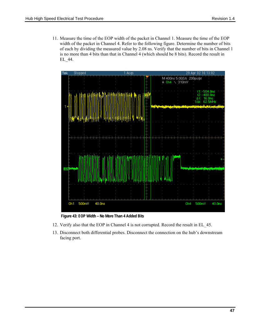
11. Measure the time of the EOP width of the packet in Channel 1. Measure the time of the EOP width of the packet in Channel 4. Refer to the following figure. Determine the number of bits of each by dividing the measured value by 2.08 ns. Verify that the number of bits in Channel 1 is no more than 4 bits than that in Channel 4 (which should be 8 bits). Record the result in EL_44.
Figure 43: EOP Width – No More Than 4 Added Bits
12. Verify also that the EOP in Channel 4 is not corrupted. Record the result in EL_45.
13. Disconnect both differential probes. Disconnect the connection on the hub’s downstream facing port.
47

Hub High Speed Electrical Test Procedure Revision 1.4
3.17 Hub CHIRP Timing – Upstream Facing Port (EL_28, EL_29, EL_31) This test applies only to the upstream facing port of the hub under test.
1. Attach the INIT port of the Device High-speed Signal Quality section of the test fixture into a high-speed capable port of the HS host controller.
2. Connect Channel 2 and Channel 3 FET probes to the test fixture at J310. Connect Ch2 to D- and Ch3 to D+. Connect the probe grounds.
3. Launch the TDSUSB software application on the oscilloscopes. For more details, refer to Starting the application.
4. In the applications menu bar of TDSUSB2.0 select, File> Recall Default.
5. Within the USB2.0 compliance test application, select the High Speed tab.
6. Click the Chirp button on the application and select the Device option EL_28, EL_29, EL_31. Click Run.
7. Connect the upstream facing port of the device under test into the TEST port of the test fixture.
8. Click Enumerate Bus and capture the CHIRP handshake as in the following figure.
Note: Instead of enumerating the device, an alternative method to generate the chirp signal, is to disconnect and reconnect the unit under test (device) to the port.
Figure 44: Device Chirp (Speed Detection)
48

Hub High Speed Electrical Test Procedure Revision 1.4
9. The EL_28 checks the device’s CHIRP-K latency in response to the reset from the host port. The time should be between 2.5 μs and 6.0 ms.
Figure 45: Device Chirp-K Latency
10. The EL_29 checks the device’s CHIRP-K duration. The assertion time should be between 1.0 ms and 7.0 ms.
49

Hub High Speed Electrical Test Procedure Revision 1.4
11. Following the host assertion of Chirp K-J-K-J-K-J, the device must respond by turning on its high-speed terminations. This is evident by a drop of amplitude of the alternate Chirp-K and Chirp-J sequence from the 800 mV nominal to the 400 mV nominal. Measure the time from the beginning of the last J in the Chirp K-J-K-J-K-J (3 pairs of Chirp-K-J’s) to the time when the device turns on the high-speed terminations. Verify that this is less than or equal to 500 μs. Record the measurement in EL_31.
Figure 46: Time From Start of Last J in Chirp K-J-K-J-K-J To Device Turns on HS Termination
12. In addition to turning on its high-speed terminations, the device must also disconnect the D+ pull-up resistor in response to the host’s assertion of Chirp K-J-K-J-K-J. The evidence is a slight drop of the D+ level during the Chirp-K from the host. Measure the time from the beginning of the last J in the Chirp K-J-K-J-K-J (3 pairs of Chirp-K-J’s) to the time when the D+ pull-up resistor is disconnected. Verify that this is less than or equal to 500 μs. Record the measurement in EL_31.
50

Hub High Speed Electrical Test Procedure Revision 1.4
3.18 Hub Suspend/Resume/Reset Timing – Upstream Facing Port (EL_27, EL_28, EL_38, EL_39, EL_40) 1. Plug the Init port of the Device High-speed Signal Quality section of the test fixture into a
high-speed capable port of the test bed computer.
2. Connect the device under test into the Test port of the test fixture. Click the Enumerate Bus button once to enumerate the newly connected device. The device under test should be enumerated with the device’s VID shown together with the root port to which it is connected.
3. Connect Channel 2 and Channel 3 FET probes to the test fixture at J310. Connect Channel 2 to D- and Channel 3 to D+. Connect the probe grounds.
4. Select the High Speed measurement tab> More button> Suspend measurement.
5. Set the input Signal Direction and run the measurements.
51

Hub High Speed Electrical Test Procedure Revision 1.4
6. On the HS Electrical Test Tool - Hub Test menu, select SUSPEND from the Hub Command dropdown menu. Click EXECUTE once to place the device into suspend. The captured suspend transition should appear as in the following figure:
Figure 47: Response to Suspend from Host - Upstream Facing Port
7. The result contains EL_38, which is the time interval from the end of last SOF packet issued by the hub to when the hub attached its full speed pull-up resistor on D+. This is the time between the END of the last SOF packet and the rising edge transition to full speed J-state. The time should be between 3.000 ms and 3.125 ms.
8. Ensure the oscilloscope is armed. Press Force Trigger to verify that the device is still in the suspend state. The D+ should be at 3.3 V nominal. The D- should be less than 0.7 V. Record the Pass/Fail result in EL_39.
52
Hub High Speed Electrical Test Procedure Revision 1.4
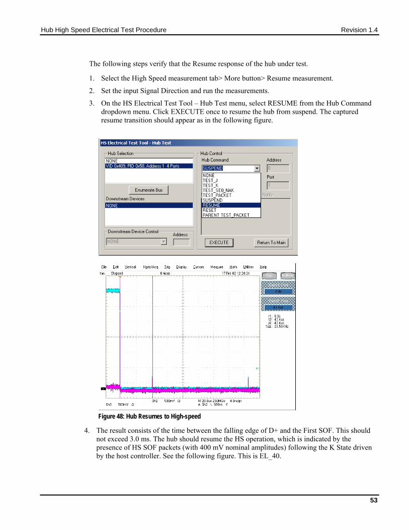
The following steps verify that the Resume response of the hub under test.
1. Select the High Speed measurement tab> More button> Resume measurement.
2. Set the input Signal Direction and run the measurements.
3. On the HS Electrical Test Tool – Hub Test menu, select RESUME from the Hub Command dropdown menu. Click EXECUTE once to resume the hub from suspend. The captured resume transition should appear as in the following figure.
Figure 48: Hub Resumes to High-speed
4. The result consists of the time between the falling edge of D+ and the First SOF. This should not exceed 3.0 ms. The hub should resume the HS operation, which is indicated by the presence of HS SOF packets (with 400 mV nominal amplitudes) following the K State driven by the host controller. See the following figure. This is EL_40.
53

Hub High Speed Electrical Test Procedure Revision 1.4
The following steps verify that the hub resumes back to high-speed operation after being reset from operating in high-speed.
1. Select the High-Speed measurement tab> More button> Reset High Speed measurement.
2. On the HS Electrical Test Tool – Hub Test menu, select RESET from the Hub Command dropdown menu. Click EXECUTE once to reset the hub operating in high-speed. The captured resume transition should appear as in the following figure.
Figure 49: Hub’s Chirp-K in Response to Reset from High-speed
3. The device should transmit a chirp handshake following the reset. Measure the time between the beginning of the last SOF before the rest and the start of the device Chirp-K. Verify that this is between 3.1 ms and 6 ms. Record the Pass/Fail result in EL_27.
The following steps verify that the hub’s chirp response after being reset from suspend.
1. Select the High-Speed measurement tab> More button> Reset from Suspend measurement.
54

Hub High Speed Electrical Test Procedure Revision 1.4
2. On the HS Electrical Test Tool – Hub Test menu, select SUSPEND from the Hub Command dropdown menu. Click EXECUTE once to place the device into suspend.
Figure 50: Hub Suspend
3. Ensure that the oscilloscope is armed. Toggle trigger mode from Auto until an acquisition is made to verify that the device is still in the suspend state. The D+ should be at 3.3 V nominal. The D- should be less than 0.7 V.
4. Ensure that the oscilloscope is armed. On the HS Electrical Test Tool – Hub Test menu, select RESET from the Hub Command dropdown menu. Click EXECUTE once to reset the device in suspend. The captured reset from suspend transition should appear as in the following figure.
Figure 51: Hub Reset From Suspend
55

Hub High Speed Electrical Test Procedure Revision 1.4
b Figure 52: Device Reset from Suspend
5. The hub responds to the reset with the Chirp-K. Measure the time between the falling edge of the D+ and the start of the device chirp-K. Verify that this is between 2.5 μs and 3 ms. This is EL_28.
3.19 Hub Test J/K, SE0_NAK – Upstream Facing Port (EL_8, EL_9) 1. Attach the USB cable to the designated power supply to J310 of the Tektronix Compliance
Test Fixture Device High-speed Signal Quality test segment.
2. Verify that the red Power LED is lit, and the red Init LED is on.
3. Connect the Test port of the Device High-speed Signal Quality test segment into the upstream facing port of the hub under test. Connect the Init port of the test fixture to a port of the Test Bed Computer. Apply power to the hub. Click Enumerate Bus button once. Verify that it is enumerated in the HS Electrical Test Tool – Hub Test menu.
56

Hub High Speed Electrical Test Procedure Revision 1.4
4. On the HS Electrical Test Tool – Hub Test menu select TEST_J from the Hub Command dropdown menu. Click EXECUTE once to place the hub into TEST_J test mode.
Figure 53: Hub Test_J from Resume
5. Switch the test fixture into the TEST position. Using a DVM measure the DC voltage on the D+ line at J310 with respect to ground (outside pins of the J310 header are ground pins). Record in section EL_8.
6. Using a DVM measure the DC voltage on the D- line at J310 with respect to ground. Record in section EL_8. Return the Test switch to the NORMAL position.
7. Cycle the hub power. This restores the hub to normal operation.
8. On the HS Electrical Test Tool – Hub Test menu click Enumerate Bus, select TEST_K from the Hub Command dropdown menu. Click EXECUTE once to place the hub into TEST_K test mode.
9. Switch the test fixture into the TEST position. Using a DVM measure the DC voltage on the D+ line at J310 with respect to ground (outside pins of J310 header are ground pins). Record in section EL_8.
10. Using a DVM measure the DC voltage on the D- line at J310 with respect to ground. Record in section EL_8. Return the Test switch to the NORMAL position.
11. Cycle the hub power. This restores the hub to normal operation.
12. On the HS Electrical Test Tool – Hub Test menu click Enumerate Bus once. Select TEST_SE0_NAK from the Hub Command dropdown menu. Click EXECUTE once to place the hub into TEST_SE0_NAK test mode.
13. Switch the test fixture into the TEST position. Using a DVM measure the DC voltage on the D+ line at J310 with respect to ground (outside pins of J310 header are ground pins). Record in section EL_9.
14. Using a DVM measure the DC voltage on the D- line at J310 with respect to ground (outside pins of J310 header are ground pins). Record in section EL_9. Return the Test switch to the NORMAL position.
15. Cycle the hub power to prepare the hub for subsequent tests.
57

Hub High Speed Electrical Test Procedure Revision 1.4
3.20 Hub Test J/K, SE0_NAK – Downstream Facing Ports (EL_8, EL_9) 1. Attach the USB cable to the designated power supply to Host Signal Quality test fixture (J35)
and verify that the red Power LED is lit. Place the TEST Switch (S6) in the INIT position. Verify that the red INIT LED is lit.
2. Attach the test fixture into the downstream facing port under test. Apply power to the hub.
3. On the HS Electrical Test Tool – Hub Test menu click Enumerate Bus once. Select TEST_J from the Port Control dropdown menu. Enter the port number and click EXECUTE once to place the port under test into TEST_J test mode.
Figure 54: Hub Test_J
4. Using a DVM measure the DC voltage on the D+ line at J310 with respect to ground (outside pins of J310 header are ground pins). Record in section EL_8.
5. Using a DVM measure the DC voltage on the D- line at J310 with respect to ground. Record in section EL_8.
6. On the HS Electrical Test Tool – Hub Test menu click Enumerate Bus once. Select TEST_K from the Port Control dropdown menu. Enter the port number and click EXECUTE once to place the port under test into TEST_K test mode.
7. Using a DVM measure the DC voltage on the D+ line at J310 with respect to ground (outside pins of J310 header are ground pins). Record in section EL_8.
8. Using a DVM measure the DC voltage on the D- line at J310 with respect to ground. Record in section EL_8.
9. On the HS Electrical Test Tool – Hub Test menu click Enumerate Bus once. Select TEST_SE0_NAK from the Port Control dropdown menu. Enter the port number and click EXECUTE once to place the port under test into TEST_SE0_NAK test mode.
58

Hub High Speed Electrical Test Procedure Revision 1.4
10. Using a DVM measure the DC voltage on the D+ line at J310 with respect to ground (outside pins of J310 header are ground pins). Record in section EL_9.
11. Using a DVM measure the DC voltage on the D- line at J310 with respect to ground (outside pins of J310 header are ground pins). Record in section EL_9.
12. Repeat steps 2 through 11 for the remaining ports.
Note: A specific port fails to enter the specific test mode after test mode commands have been issued to the hub a number of times. Cycle power on the hub will alleviate this problem.
59

Hub High Speed Electrical Test Procedure Revision 1.4
60
Appendix A
A.1 Hub High-speed Electrical Test Data This section is for recording the actual test result. Please use a copy for each device to be tested.
A.1.1 Vendor and Product Information
Please fill in all fields. Please contact your silicon supplier if you are unsure of the silicon information
Test Date
Vendor Name
Vendor Complete Address
Vendor Phone Number
Vendor Contact, Title
Test ID Number
Product Name
Product Model and Revision
USB Silicon Vendor Name
USB Silicon Model
USB Silicon Part Marking
USB Silicon Stepping
Tested By

Hub High Speed Electrical Test Procedure Revision 1.4
61
A.1.2 Legacy USB Compliance Tests Legacy USB Compliance Checklist
Legacy Test Pass/Fail Comments
LS SQ (Downstream)
FS SQ (Upstream and Downstream)
Inrush (Upstream)
Drop/Droop (Downstream)
Interop
P = PASS
F = FAIL
N/A = Not applicable
A.1.3 Hub High-speed Signal Quality – Upstream Facing Port (EL_2, EL_46, EL_6, EL_7) EL_2 A USB 2.0 high-speed transmitter data rate must be 480 Mb/s ±0.05%.
Reference documents: USB 2.0 Specification, Section 7.1.11.
Pass Fail N/A
Comments:
EL_46 A hub upstream repeater must meet Template 1 transform waveform requirements measured at TP3.
Reference documents: USB 2.0 Specification, Section 7.1.2.2.
Hub High Speed Electrical Test Procedure Revision 1.4
62
Pass Fail N/A
Comments:
EL_6 A USB 2.0 HS driver must have 10% to 90% differential rise and fall times of greater than 500 ps.
Reference documents: USB 2.0 Specification, Section 7.1.2.2. Pass Fail N/A
Comments:
EL_7 A USB 2.0 HS driver must have monotonic data transitions over the vertical openings specified in the appropriate eye pattern template.
Reference documents: USB 2.0 Specification, Section 7.1.2.2. Pass Fail N/A
Comments:
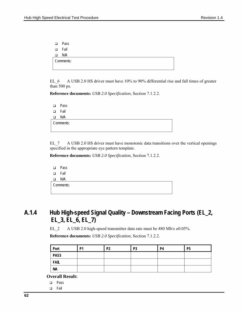
A.1.4 Hub High-speed Signal Quality – Downstream Facing Ports (EL_2, EL_3, EL_6, EL_7) EL_2 A USB 2.0 high-speed transmitter data rate must be 480 Mb/s ±0.05%.
Reference documents: USB 2.0 Specification, Section 7.1.2.2.
Port P1 P2 P3 P4 P5 PASS FAIL NA
Overall Result: Pass Fail

Hub High Speed Electrical Test Procedure Revision 1.4
63
N/A Comments:
EL_3 A USB 2.0 downstream-facing port must meet Template 1 transform waveform requirements measured at TP2 (each hub downstream port).
Reference documents: USB 2.0 Specification, Section 7.1.2.2.
Port P1 P2 P3 P4 P5 PASS FAIL NA
Overall Result: Pass Fail N/A
Comments:
EL_6 A USB 2.0 HS driver must have 10% to 90% differential rise and fall times of greater than 500 ps.
Reference documents: USB 2.0 Specification, Section 7.1.2.2.
Port P1 P2 P3 P4 P5 PASS FAIL NA
Pass Fail N/A
Comments:
EL_7 A USB 2.0 HS driver must have monotonic data transitions over the vertical openings specified in the appropriate eye pattern template.
Reference documents: USB 2.0 Specification, Section 7.1.2.2.
Port P1 P2 P3 P4 P5

Hub High Speed Electrical Test Procedure Revision 1.4
64
PASS FAIL NA
Pass Fail N/A
Comments:
A.1.5 Hub Jitter – Downstream Facing Ports (EL_47) EL_47 A hub downstream-facing repeater must meet Template 1 transform waveform requirements measured at TP2 (each hub downstream port).
Reference documents: USB 2.0 Specification, Section 7.1.14.2.
Port P1 P2 P3 P4 P5 PASS FAIL NA
Overall Result:
Pass Fail N/A
Comments:

Hub High Speed Electrical Test Procedure Revision 1.4
65
A.1.6 Hub Disconnect Detect (EL_36, EL37) EL_37 A USB 2.0 downstream-facing port must not detect the high-speed disconnect state when the amplitude of the differential signal at the downstream facing driver’s connector is <= 525 mV.
Reference documents: USB 2.0 Specification, Section 7.1.7.3.
Port P1 P2 P3 P4 P5 PASS FAIL NA
Overall:
Pass Fail N/A
Comments:
EL_36 A USB 2.0 downstream-facing port must detect the high-speed disconnect state when the amplitude of the differential signal at the downstream facing driver’s connector is ≥ 625 mV.
Reference documents: USB 2.0 Specification, Section 7.1.7.3.
Port P1 P2 P3 P4 P5 PASS FAIL NA
Overall Result: Pass Fail N/A
Comments:

Hub High Speed Electrical Test Procedure Revision 1.4
66
A.1.7 Hub Packet Parameters – Upstream Facing Port (EL_21, EL_22, EL_25) EL_21 The SYNC field for all transmitted packets (not repeated packets) must begin with a 32-bit SYNC field.
Reference documents: USB 2.0 Specification, Section 8.2. Data Packet SYNC field
Pass Fail N/A
Comments:
EL_25 The EOP for all transmitted packets (except SOFs) must be an 8-bit NRZ byte of 01111111 without bit stuffing. (Note that a longer EOP is waiverable)
Reference documents: USB 2.0 Specification, Section 7.1.13.2 Pass Fail N/A
Comments:
EL_22 When transmitting after receiving a packet, hosts and devices must provide an inter-packet gap of at least 8 bit times and not more than 192 bit times.
Reference documents: USB 2.0 Specification, Section 7.1.18.2. Pass Fail N/A
Comments:

Hub High Speed Electrical Test Procedure Revision 1.4
67
A.1.8 Hub Receiver Sensitivity – Upstream Facing Port (EL_16, EL_17, EL_18) EL_18 A high-speed capable device’s Transmission Envelope Detector must be fast enough to allow the HS receiver to detect data transmission, achieve DLL lock, and detect the end of the SYNC field within 12 bit times.
Reference documents: USB 2.0 Specification, Section 7.1. Pass Fail N/A
Comments:
EL_17 A high-speed capable device must implement a transmission envelope detector that does not indicate squelch (that is, reliably receives packets) when a receiver exceeds 150 mV differential amplitude.
Note: A waiver may be granted if the receiver does not indicate Squelch at +/-50 mV of 150 mV differential amplitude. This is to compensate for the oscilloscope probe point away from the receiver pins.
Reference documents: USB 2.0 Specification, Section 7.1. Pass Fail N/A
Comments:
EL_16 A high-speed capable device must implement a transmission envelope detector that indicates squelch (that is, never receives packets) when a receiver’s input falls below 100 mV differential amplitude.
Note: A waiver may be granted if the receiver indicates Squelch at +/-50 mV of 100 mV differential amplitude. This is to compensate for the oscilloscope probe point away from the receiver pins.
Reference documents: USB 2.0 Specification, Section 7.1. Pass Fail N/A
Comments:
Hub High Speed Electrical Test Procedure Revision 1.4
68
A.1.9 Hub Repeater Test – Downstream Facing Ports (EL_42, EL_43, EL_44, EL_45, EL_48) EL_48 A hub repeater may not delay packets for more than 36 bit times plus 4 ns.
Reference documents: USB 2.0 Specification, Section 7.1.14.2 Pass Fail N/A
Comments:
EL_42 Hub repeaters must not truncate more than 4 bits from a repeated SYNC pattern.
Reference documents: USB 2.0 Specification, Section 7.1.10. Pass Fail N/A
Comments:
EL_43 Hubs must not corrupt any repeated bits of the SYNC field.
Reference documents: USB 2.0 Specification, Section 7.1.10. Pass Fail N/A
Comments:
Hub High Speed Electrical Test Procedure Revision 1.4
69
EL_44 A hub may add at most 4 random bits to the end of the EOP field when repeating a packet.
Reference documents: USB 2.0 Specification, Section 7.1.13.2 Pass Fail N/A
Comments:
EL_45 A hub must not corrupt any of the valid EOP bits when repeating a packet.
Reference documents: USB 2.0 Specification, Section 7.1.13.2 Pass Fail N/A
Comments:
A.1.10 Hub Repeater Test – Upstream Facing Port (EL_42, EL_43, EL_44,
EL_45) EL_42 Hub repeaters must not truncate more than 4 bits from a repeated SYNC pattern.
Reference documents: USB 2.0 Specification, Section 7.1.10. Pass Fail N/A
Comments:
EL_43 Hubs must not corrupt any repeated bits of the SYNC field.
Reference documents: USB 2.0 Specification, Section 7.1.10.

Hub High Speed Electrical Test Procedure Revision 1.4
70
Pass Fail N/A
Comments:
EL_44 A hub may add at most 4 random bits to the end of the EOP field when repeating a packet.
Reference documents: USB 2.0 Specification, Section 7.1.13.2 Pass Fail N/A
Comments:
EL_45 A hub must not corrupt any of the valid EOP bits when repeating a packet.
Reference documents: USB 2.0 Specification, Section 7.1.13.2 Pass Fail N/A
Comments:
A.1.11 Hub CHIRP Timing – Upstream Facing Port (EL_28, EL_29, EL_31) EL_28 Devices must transmit a chirp handshake no sooner than 2.5 μs and no later than 3 ms when being reset from suspend or a full-speed state.
Reference documents: USB 2.0 Specification, Section 7.1.7.5. Pass Fail N/A
Comments:
EL_29 The chirp handshake generated by a device must be at least 1 ms and not more than 7 ms in duration.

Hub High Speed Electrical Test Procedure Revision 1.4
71
Reference documents: USB 2.0 Specification, Section 7.1.7.5. Pass Fail N/A
Comments:
EL_31 During device speed detection, when a device detects a valid Chirp K-J-K-J-K-J sequence, the device must disconnect its 1.5K pull-up resistor and enable its high-speed terminations within 500 μs.
Reference documents: USB 2.0 Specification, Section 7.1.7.5.
Pass Fail N/A
Comments:
A.1.12 Hub Suspend/Resume/Reset Timing – Upstream Facing Port (EL_27,
EL_28, EL_38, EL_39, EL_40)
EL_38 A device must revert to full-speed termination no later than 125 μs after there is a 3 ms idle period on the bus.
Reference documents: USB 2.0 Specification, Section 7.1.7.6. Pass Fail N/A
Comments:

Hub High Speed Electrical Test Procedure Revision 1.4
72
EL_39 A device must support the Suspend state.
Reference documents: USB 2.0 Specification, Section 7.1.7.6.
Pass Fail N/A
Comments:
EL_40 If a device is in the suspend state, and was operating in high-speed before being suspended, then device must transition back to high-speed operation within two bit times from the end of resume signaling.
Note: It is not feasible to measure the hub transition back to high-speed operation within two-bit time from the end of the resume signaling. The presence of SOF at nominal 400 mV amplitude following the resume signaling is sufficient for this test.
Reference documents: USB 2.0 Specification, Section 7.1.7.7.
Pass Fail N/A
Comments:
EL_27 Devices must transmit a chirp handshake no sooner than 3.1 ms and no later than 6 ms when being reset from a non-suspended high-speed mode. The timing is measured from the beginning of the last uSOF transmitted before the reset begins.
Reference documents: USB 2.0 Specification, Section 7.1.7.5.
Pass Fail N/A
Comments:
EL_28 Devices must transmit a chirp handshake no sooner than 2.5 μs and no later than 3 ms when being reset from suspend or a full-speed state.
Reference documents: USB 2.0 Specification, Section 7.1.7.5.

Hub High Speed Electrical Test Procedure Revision 1.4
73
Pass Fail N/A
Comments:
A.1.13 Hub Test J/K, SE0_NAK - Upstream Facing Port (EL_8, EL_9) EL_8 When either D+ or D- are driven high, the output voltage must be 400 mV ±10% when terminated with precision 45 Ω resistors to ground.
Reference documents: USB 2.0 Specification, Section 7.1.1.3.
Test D+ Voltage (mV) D- Voltage (mV) J K
Pass Fail N/A
Comments:
EL_9 When either D+ and D- are not being driven, the output voltage must be 0 V ±10 mV when terminated with precision 45 Ω resistors to ground.
Reference documents: USB 2.0 Specification, Section 7.1.1.3.
Voltage (mV) D+ D-
Pass Fail N/A
Comments:

Hub High Speed Electrical Test Procedure Revision 1.4
74
A.1.14 Hub Test J/K, SE0_NAK – Downstream Facing Ports (EL_8, EL_9) EL_8 When either D+ or D- are driven high, the output voltage must be 400 mV ±10% when terminated with precision 45 Ω resistors to ground.
Reference documents: USB 2.0 Specification, Section 7.1.1.3.
Port 1 2 3 4 5 Test D+ D- D+ D- D+ D- D+ D- D+ D- TEST_J TEST_K
Pass Fail N/A
Comments:
EL_9 When either D+ and D- are not being driven, the output voltage must be 0 V ±10 mV when terminated with precision 45 Ω resistors to ground.
Reference documents: USB 2.0 Specification, Section 7.1.1.3.
Port 1 2 3 4 5 Signal D+ D- D+ D- D+ D- D+ D- D+ D- Measure WRT Ground (mV)
Pass Fail N/A
Comments: