hpkm column shoe
TRANSCRIPT
Version: Peikko Group 5/2014
Approved: European Technical Approval ETA-13/0603
HPKM Column ShoeFor bolted column connections
Technical Manual
HPKM Column ShoeFor bolted column connections
System benefi ts• The stiff ness of Peikko’s column connection is verifi ed at
least as rigid as continuously reinforced cast-in-situ column
connection by experimental concrete units tests
• Fast and easy erection of the column with good adjustment
possibilities
• No need for temporary bracing during erection stage
• No need for welding on site
• Easy to design with free Peikko Designer®
software
• First approved and completely analyzed
precast column connection on the market
(stiff ness, bending, shear and fi re resistances)
• Approved by EOTA, granted European
Technical Approval ETA-13/0603
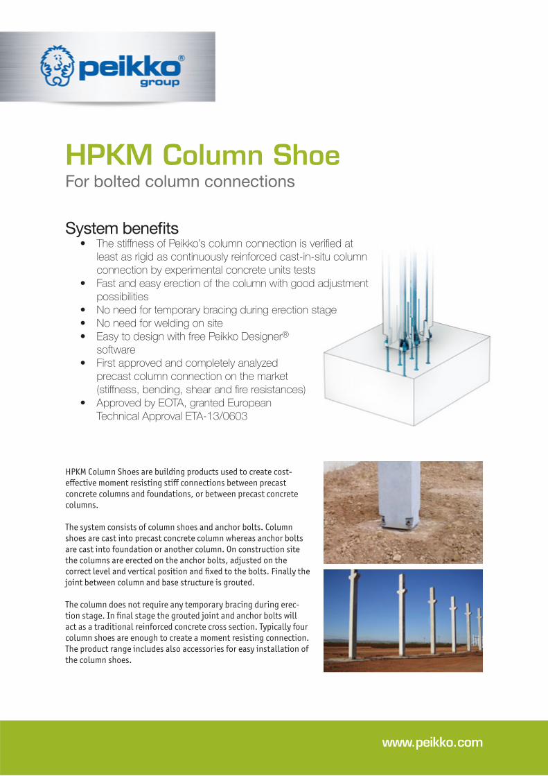
HPKM Column Shoes are building products used to create cost-
eff ective moment resisting stiff connections between precast
concrete columns and foundations, or between precast concrete
columns.
The system consists of column shoes and anchor bolts. Column
shoes are cast into precast concrete column whereas anchor bolts
are cast into foundation or another column. On construction site
the columns are erected on the anchor bolts, adjusted on the
correct level and vertical position and fi xed to the bolts. Finally the
joint between column and base structure is grouted.
The column does not require any temporary bracing during erec-
tion stage. In fi nal stage the grouted joint and anchor bolts will
act as a traditional reinforced concrete cross section. Typically four
column shoes are enough to create a moment resisting connection.
The product range includes also accessories for easy installation of
the column shoes.
www.peikko.com
1. Product properties ....................................4
1.1 Structural behavior . . . . . . . . . . . . . . . . . . . . . . . . . . . 5
1.1.1 Temporary conditions 5
1.1.2 Final conditions 5
1.2 Application conditions . . . . . . . . . . . . . . . . . . . . . . . . 6
1.2.1 Loading and environmental conditions 6
1.2.2 Interaction with column 7
1.2.3 Positioning of the column shoe 7
1.3 Other properties . . . . . . . . . . . . . . . . . . . . . . . . . . . . . . 8
2. Resistances ..............................................9
2.1 Axial resistances . . . . . . . . . . . . . . . . . . . . . . . . . . . . . 9
2.2 Shear resistances. . . . . . . . . . . . . . . . . . . . . . . . . . . . 10
2.3 Fire resistances . . . . . . . . . . . . . . . . . . . . . . . . . . . . . 11
About HPKM Column Shoe 4
12Selecting HPKM Column Shoe
14
16
18Installation of HPKM Column Shoe
Contents
Install the Product – Precast factory .............18
Install the Product – Construction site ...........20
Revision: 002
Annex A – Transverse reinforcement in the lap zone and supplementary reinforcement
Annex B – Alternative use of HPKM Column Shoe
1. Product properties
HPKM Column Shoes are available in several standard models to solve the most of
precast concrete column connections. The original Peikko column connection system
consists of:
• Column shoes
• Anchor bolts
• Accessories: recess formers and installation templates
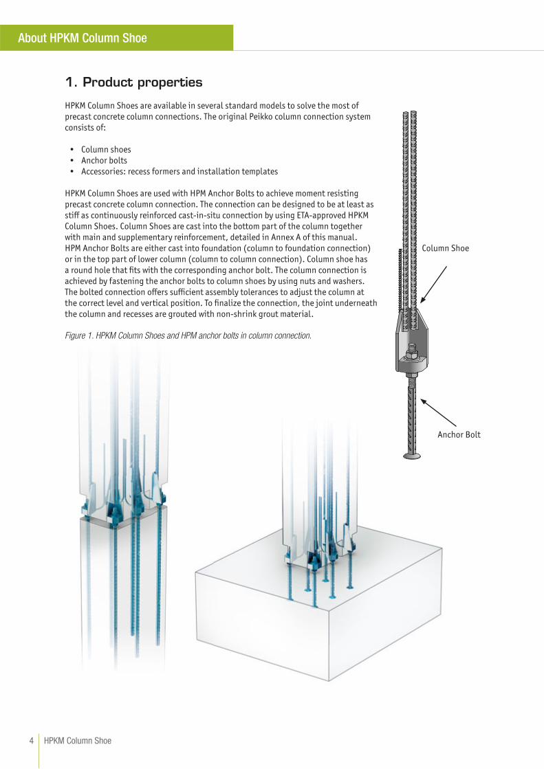
HPKM Column Shoes are used with HPM Anchor Bolts to achieve moment resisting
precast concrete column connection. The connection can be designed to be at least as
stiff as continuously reinforced cast-in-situ connection by using ETA-approved HPKM
Column Shoes. Column Shoes are cast into the bottom part of the column together
with main and supplementary reinforcement, detailed in Annex A of this manual.
HPM Anchor Bolts are either cast into foundation (column to foundation connection)
or in the top part of lower column (column to column connection). Column shoe has
a round hole that fi ts with the corresponding anchor bolt. The column connection is
achieved by fastening the anchor bolts to column shoes by using nuts and washers.
The bolted connection off ers suffi cient assembly tolerances to adjust the column at
the correct level and vertical position. To fi nalize the connection, the joint underneath
the column and recesses are grouted with non-shrink grout material.
Figure 1. HPKM Column Shoes and HPM anchor bolts in column connection.
Column Shoe
Anchor Bolt
HPKM Column Shoe4
About HPKM Column Shoe
Resistances of single HPKM Column Shoes are equal to the resistances of corresponding HPM Anchor bolts. For
more information about anchor bolts, see the Technical Manual of HPM Anchor Bolts.
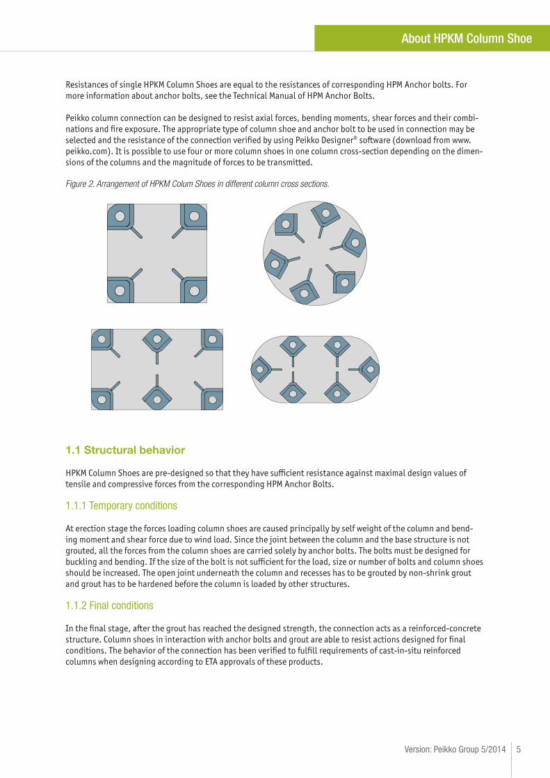
Peikko column connection can be designed to resist axial forces, bending moments, shear forces and their combi-
nations and fi re exposure. The appropriate type of column shoe and anchor bolt to be used in connection may be
selected and the resistance of the connection verifi ed by using Peikko Designer® software (download from www.
peikko.com). It is possible to use four or more column shoes in one column cross-section depending on the dimen-
sions of the columns and the magnitude of forces to be transmitted.
Figure 2. Arrangement of HPKM Colum Shoes in different column cross sections.
1.1 Structural behavior
HPKM Column Shoes are pre-designed so that they have suffi cient resistance against maximal design values of
tensile and compressive forces from the corresponding HPM Anchor Bolts.
1.1.1 Temporary conditions
At erection stage the forces loading column shoes are caused principally by self weight of the column and bend-
ing moment and shear force due to wind load. Since the joint between the column and the base structure is not
grouted, all the forces from the column shoes are carried solely by anchor bolts. The bolts must be designed for
buckling and bending. If the size of the bolt is not suffi cient for the load, size or number of bolts and column shoes
should be increased. The open joint underneath the column and recesses has to be grouted by non-shrink grout
and grout has to be hardened before the column is loaded by other structures.
1.1.2 Final conditions
In the fi nal stage, after the grout has reached the designed strength, the connection acts as a reinforced-concrete
structure. Column shoes in interaction with anchor bolts and grout are able to resist actions designed for fi nal
conditions. The behavior of the connection has been verifi ed to fulfi ll requirements of cast-in-situ reinforced
columns when designing according to ETA approvals of these products.
5Version: Peikko Group 5/2014
About HPKM Column Shoe
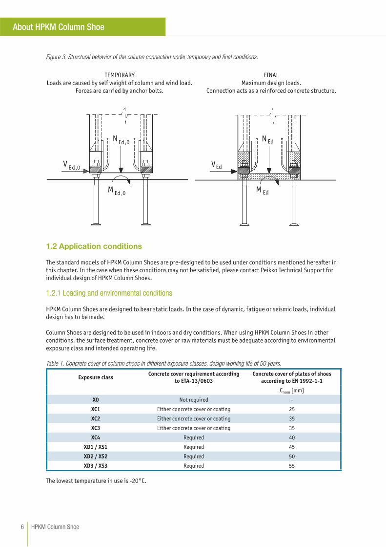
Figure 3. Structural behavior of the column connection under temporary and fi nal conditions.
N dE
M dE
V dE
N0,dE
M0,dE
V0,dE
1.2 Application conditions
The standard models of HPKM Column Shoes are pre-designed to be used under conditions mentioned hereafter in
this chapter. In the case when these conditions may not be satisfi ed, please contact Peikko Technical Support for
individual design of HPKM Column Shoes.
1.2.1 Loading and environmental conditions
HPKM Column Shoes are designed to bear static loads. In the case of dynamic, fatigue or seismic loads, individual
design has to be made.
Column Shoes are designed to be used in indoors and dry conditions. When using HPKM Column Shoes in other
conditions, the surface treatment, concrete cover or raw materials must be adequate according to environmental
exposure class and intended operating life.
Table 1. Concrete cover of column shoes in different exposure classes, design working life of 50 years.
Exposure classConcrete cover requirement according
to ETA-13/0603
Concrete cover of plates of shoes
according to EN 1992-1-1
Cnom [mm]
X0 Not required -
XC1 Either concrete cover or coating 25
XC2 Either concrete cover or coating 35
XC3 Either concrete cover or coating 35
XC4 Required 40
XD1 / XS1 Required 45
XD2 / XS2 Required 50
XD3 / XS3 Required 55
The lowest temperature in use is -20°C.
TEMPORARY
Loads are caused by self weight of column and wind load.
Forces are carried by anchor bolts.
FINAL
Maximum design loads.
Connection acts as a reinforced concrete structure.
HPKM Column Shoe6
About HPKM Column Shoe
1.2.2 Interaction with column
HPKM Columns Shoes are pre-designed to be used in reinforced concrete columns with minimum dimensions sum-
marized in Table 2. If column shoes must be placed in the column with smaller dimensions, please contact Peikko
Technical Support.
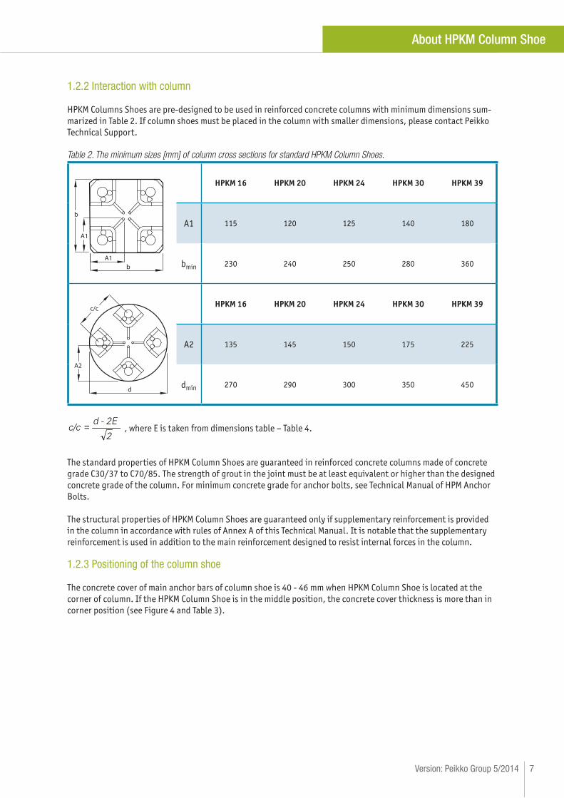
Table 2. The minimum sizes [mm] of column cross sections for standard HPKM Column Shoes.
b
bA1
A1
HPKM 16 HPKM 20 HPKM 24 HPKM 30 HPKM 39
A1 115 120 125 140 180
bmin 230 240 250 280 360
d
c/c
A2
HPKM 16 HPKM 20 HPKM 24 HPKM 30 HPKM 39
A2 135 145 150 175 225
dmin 270 290 300 350 450
2
d - 2Ec/c =
The standard properties of HPKM Column Shoes are guaranteed in reinforced concrete columns made of concrete
grade C30/37 to C70/85. The strength of grout in the joint must be at least equivalent or higher than the designed
concrete grade of the column. For minimum concrete grade for anchor bolts, see Technical Manual of HPM Anchor
Bolts.
The structural properties of HPKM Column Shoes are guaranteed only if supplementary reinforcement is provided
in the column in accordance with rules of Annex A of this Technical Manual. It is notable that the supplementary
reinforcement is used in addition to the main reinforcement designed to resist internal forces in the column.
1.2.3 Positioning of the column shoe
The concrete cover of main anchor bars of column shoe is 40 - 46 mm when HPKM Column Shoe is located at the
corner of column. If the HPKM Column Shoe is in the middle position, the concrete cover thickness is more than in
corner position (see Figure 4 and Table 3).
, where E is taken from dimensions table – Table 4.
7Version: Peikko Group 5/2014
About HPKM Column Shoe
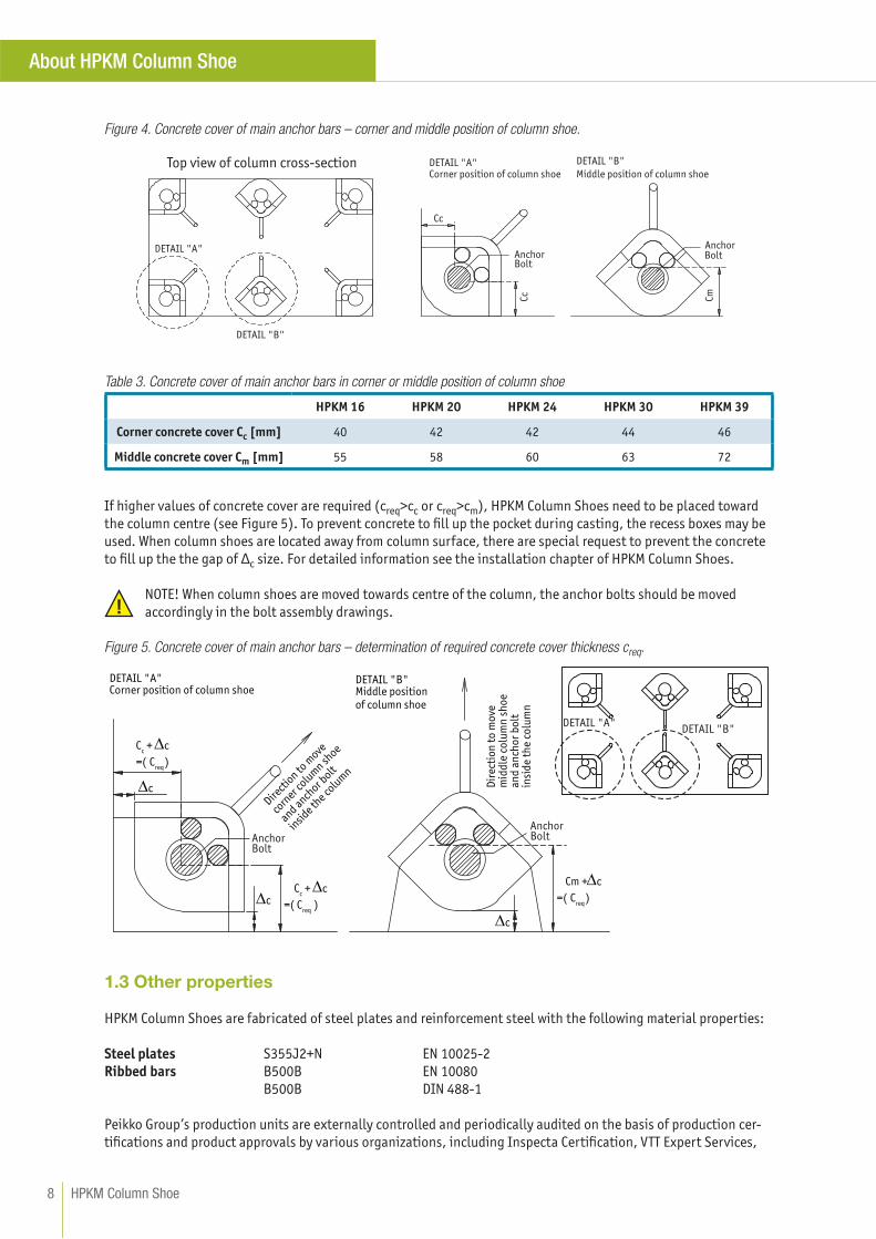
Figure 4. Concrete cover of main anchor bars – corner and middle position of column shoe.
Cc
AnchorBolt
AnchorBolt
Cc Cm
DETAIL "A"
DETAIL "B"
DETAIL "A"Corner position of column shoe
DETAIL "B"
Middle position of column shoe
Table 3. Concrete cover of main anchor bars in corner or middle position of column shoe
HPKM 16 HPKM 20 HPKM 24 HPKM 30 HPKM 39
Corner concrete cover Cc [mm] 40 42 42 44 46
Middle concrete cover Cm [mm] 55 58 60 63 72
If higher values of concrete cover are required (creq>cc or creq>cm), HPKM Column Shoes need to be placed toward
the column centre (see Figure 5). To prevent concrete to fi ll up the pocket during casting, the recess boxes may be
used. When column shoes are located away from column surface, there are special request to prevent the concrete
to fi ll up the the gap of Δc size. For detailed information see the installation chapter of HPKM Column Shoes.
NOTE! When column shoes are moved towards centre of the column, the anchor bolts should be moved
accordingly in the bolt assembly drawings.
Figure 5. Concrete cover of main anchor bars – determination of required concrete cover thickness creq.
DETAIL "A"DETAIL "B"
Cc + c
=( Creq
c
DETAIL "A"Corner position of column shoe
DETAIL "B"Middle positionof column shoe
cC
c + c
)
Direct
ion to
move
corn
er colu
mn sh
oe
and anchor b
olt
insid
e the co
lum
n
Cm + c
=( Creq
)
Dir
ecti
on
to
mo
vem
idd
le c
olu
mn
sh
oe
and
an
cho
r b
olt
in
sid
e th
e co
lum
n
= Creq
c
(
)
AnchorBolt
AnchorBolt
1.3 Other properties
HPKM Column Shoes are fabricated of steel plates and reinforcement steel with the following material properties:
Steel plates S355J2+N EN 10025-2
Ribbed bars B500B EN 10080
B500B DIN 488-1
Peikko Group’s production units are externally controlled and periodically audited on the basis of production cer-
tifi cations and product approvals by various organizations, including Inspecta Certifi cation, VTT Expert Services,
Top view of column cross-section
HPKM Column Shoe8
About HPKM Column Shoe
Nordcert, SLV, TSUS and SPSC among others.
Products are marked with the mark of VTT Expert Services, the emblem of Peikko Group, the type of product and
year and week of manufacturing.
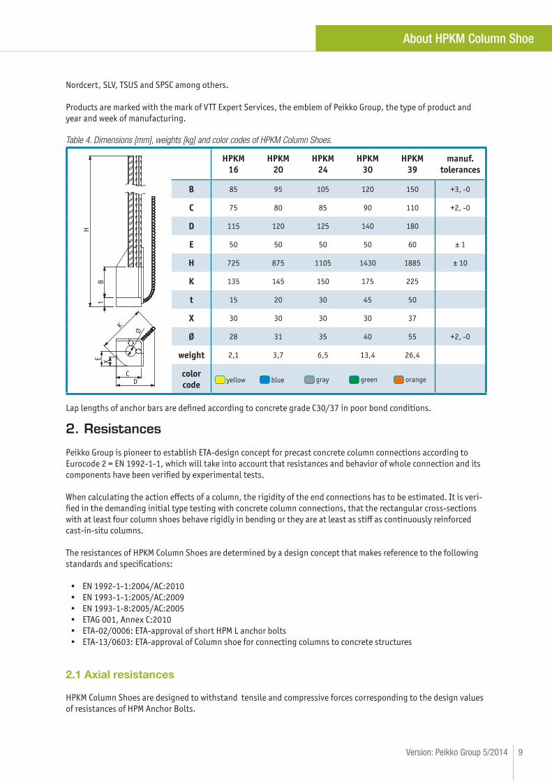
Table 4. Dimensions [mm], weights [kg] and color codes of HPKM Column Shoes.
t
H
B
C
K
D
E
X
HPKM
16
HPKM
20
HPKM
24
HPKM
30
HPKM
39
manuf.
tolerances
B 85 95 105 120 150 +3, -0
C 75 80 85 90 110 +2, -0
D 115 120 125 140 180
E 50 50 50 50 60 ± 1
H 725 875 1105 1430 1885 ± 10
K 135 145 150 175 225
t 15 20 30 45 50
X 30 30 30 30 37
Ø 28 31 35 40 55 +2, -0
weight 2,1 3,7 6,5 13,4 26,4
color
code yellow blue gray green orange
Lap lengths of anchor bars are defi ned according to concrete grade C30/37 in poor bond conditions.
2. Resistances
Peikko Group is pioneer to establish ETA-design concept for precast concrete column connections according to
Eurocode 2 = EN 1992-1-1, which will take into account that resistances and behavior of whole connection and its
components have been verifi ed by experimental tests.
When calculating the action eff ects of a column, the rigidity of the end connections has to be estimated. It is veri-
fi ed in the demanding initial type testing with concrete column connections, that the rectangular cross-sections
with at least four column shoes behave rigidly in bending or they are at least as stiff as continuously reinforced
cast-in-situ columns.
The resistances of HPKM Column Shoes are determined by a design concept that makes reference to the following
standards and specifi cations:
• EN 1992-1-1:2004/AC:2010
• EN 1993-1-1:2005/AC:2009
• EN 1993-1-8:2005/AC:2005
• ETAG 001, Annex C:2010
• ETA-02/0006: ETA-approval of short HPM L anchor bolts
• ETA-13/0603: ETA-approval of Column shoe for connecting columns to concrete structures
2.1 Axial resistances
HPKM Column Shoes are designed to withstand tensile and compressive forces corresponding to the design values
of resistances of HPM Anchor Bolts.
9Version: Peikko Group 5/2014
About HPKM Column Shoe
It is recommended to calculate the resistances of column connection by using Peikko Designer® software. Peikko
Designer® software will make column connection design procedure fast and easy. In the software there is imple-
mented a design code selection, which is required for each design case and which off ers many options to the user.
By selecting the valid design code it’s possible to check the resistances of each column connection easily. Checking
erection stage resistances of column connection when the joint is not grouted is also an implemented feature.
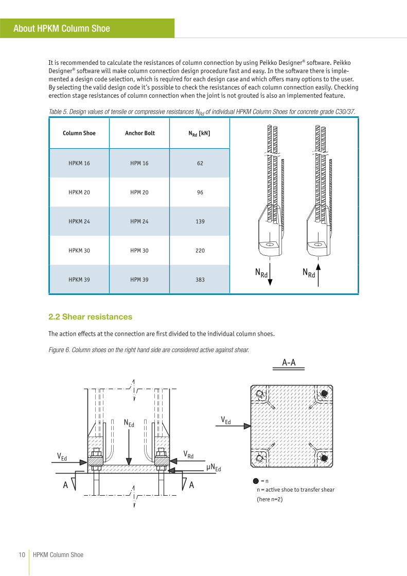
Table 5. Design values of tensile or compressive resistances NRd of individual HPKM Column Shoes for concrete grade C30/37.
Column Shoe Anchor Bolt NRd [kN]
NRd NRd
HPKM 16 HPM 16 62
HPKM 20 HPM 20 96
HPKM 24 HPM 24 139
HPKM 30 HPM 30 220
HPKM 39 HPM 39 383
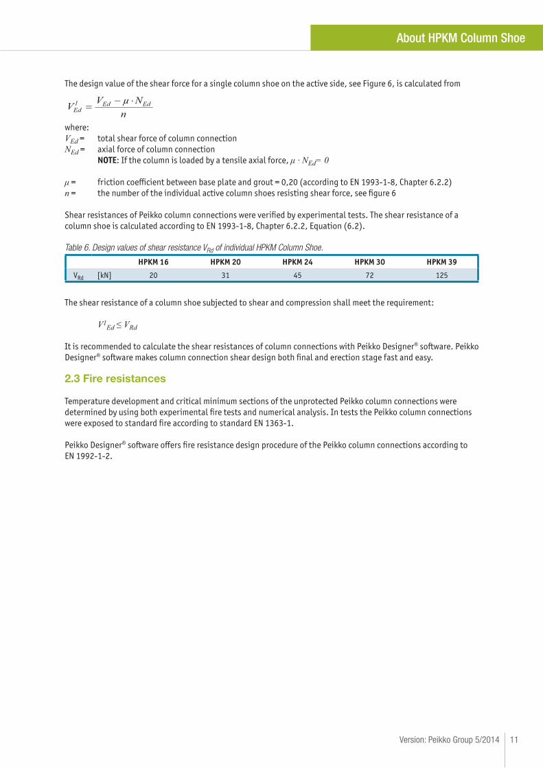
2.2 Shear resistances
The action eff ects at the connection are fi rst divided to the individual column shoes.
Figure 6. Column shoes on the right hand side are considered active against shear.
VEd
A A
A-A
NEd
μNEd
VEd
VRd
= n
n = active shoe to transfer shear
(here n=2)
HPKM Column Shoe10
About HPKM Column Shoe
The design value of the shear force for a single column shoe on the active side, see Figure 6, is calculated from
nNVV EdEd1
Edμ
where:
VEd = total shear force of column connection
NEd = axial force of column connection
NOTE: If the column is loaded by a tensile axial force, μ · NEd= 0
μ = friction coeffi cient between base plate and grout = 0,20 (according to EN 1993-1-8, Chapter 6.2.2)
n = the number of the individual active column shoes resisting shear force, see fi gure 6
Shear resistances of Peikko column connections were verifi ed by experimental tests. The shear resistance of a
column shoe is calculated according to EN 1993-1-8, Chapter 6.2.2, Equation (6.2).
Table 6. Design values of shear resistance VRd of individual HPKM Column Shoe.
HPKM 16 HPKM 20 HPKM 24 HPKM 30 HPKM 39
VRd [kN] 20 31 45 72 125
The shear resistance of a column shoe subjected to shear and compression shall meet the requirement:
V1Ed ≤ VRd
It is recommended to calculate the shear resistances of column connections with Peikko Designer® software. Peikko
Designer® software makes column connection shear design both fi nal and erection stage fast and easy.
2.3 Fire resistances
Temperature development and critical minimum sections of the unprotected Peikko column connections were
determined by using both experimental fi re tests and numerical analysis. In tests the Peikko column connections
were exposed to standard fi re according to standard EN 1363-1.
Peikko Designer® software off ers fi re resistance design procedure of the Peikko column connections according to
EN 1992-1-2.
11Version: Peikko Group 5/2014
About HPKM Column Shoe
Selecting HPKM Column Shoe
The following aspects have to be considered when selecting the appropriate type of HPKM Column Shoe to be used
in a column connection:
• Resistances
• Properties of the column
• Properties of the grout
• Position and arrangement of the column shoes in the column
• Design value of actions
The resistance of column connection should be verifi ed for the following design situations:
• Erection stage
• Final stage
• Fire situation
• Environmental exposure conditions
Peikko Designer® Column Connection software
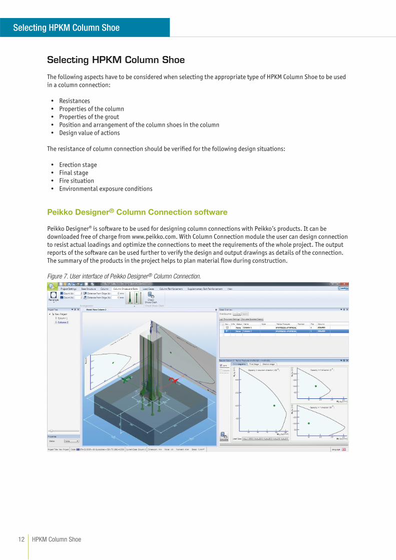
Peikko Designer® is software to be used for designing column connections with Peikko’s products. It can be
downloaded free of charge from www.peikko.com. With Column Connection module the user can design connection
to resist actual loadings and optimize the connections to meet the requirements of the whole project. The output
reports of the software can be used further to verify the design and output drawings as details of the connection.
The summary of the products in the project helps to plan material fl ow during construction.
Figure 7. User interface of Peikko Designer® Column Connection.
HPKM Column Shoe12
Selecting HPKM Column Shoe
The typical selection procedure is done in the following steps:
USER INPUT
• Materials for column, structure under column and grouting
• Geometries of the column and structure under column
• Design values of the actions – erection, fi nal and fi re stage
• Type of column shoes and anchor bolts
• Column shoe arrangement
• Column reinforcement (optional)
PEIKKO DESIGNER OUTPUT
• N-M interaction diagram (axial force-bending moment diagram) of joint in fi nal and fi re stage
• N-M interaction diagram of reinforced column
• Calculation results for column connection in fi nal stage
• Calculation results for column connection in erection stage
• Supplementary reinforcement details
• Summary of products in the project
13Version: Peikko Group 5/2014
Selecting HPKM Column Shoe
3
1
1
3
lo
lb
≤1
00
5
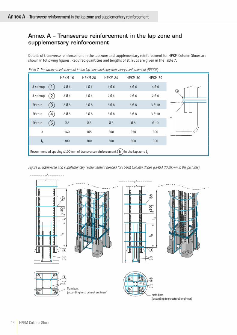
Annex A – Transverse reinforcement in the lap zone and supplementary reinforcement
Details of transverse reinforcement in the lap zone and supplementary reinforcement for HPKM Column Shoes are
shown in following fi gures. Required quantities and lengths of stirrups are given in the Table 7.
Table 7. Transverse reinforcement in the lap zone and supplementary reinforcement (B500B).
HPKM 16 HPKM 20 HPKM 24 HPKM 30 HPKM 39
3 U-stirrup 4 Ø 6 4 Ø 6 4 Ø 6 4 Ø 6 4 Ø 6
U-stirrup 2 Ø 6 2 Ø 6 2 Ø 6 2 Ø 6 2 Ø 6
Stirrup 2 Ø 8 2 Ø 8 3 Ø 8 3 Ø 8 3 Ø 10
Stirrup 2 Ø 8 2 Ø 8 3 Ø 8 3 Ø 8 3 Ø 10
Stirrup Ø 8 Ø 8 Ø 8 Ø 8 Ø 10
a 140 165 200 250 300
lb 300 300 300 300 300
Recommended spacing ≤100 mm of transverse reinforcement 5 in the lap zone l0
Figure 8. Transverse and supplementary reinforcement needed for HPKM Column Shoes (HPKM 30 shown in the pictures).
Main bars
(according to structural engineer)Main bars
(according to structural engineer)
1
2
3
4
5
3
1
lo
lb
1
3
5
≤1
00
HPKM Column Shoe14
Annex A – Transverse reinforcement in the lap zone and supplementary reinforcement
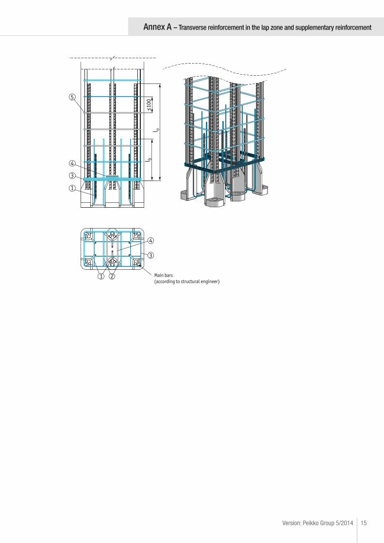
Main bars
(according to structural engineer)
4
3
1
3
4
5
21
lo
lb
≤1
00
15Version: Peikko Group 5/2014
Annex A – Transverse reinforcement in the lap zone and supplementary reinforcement
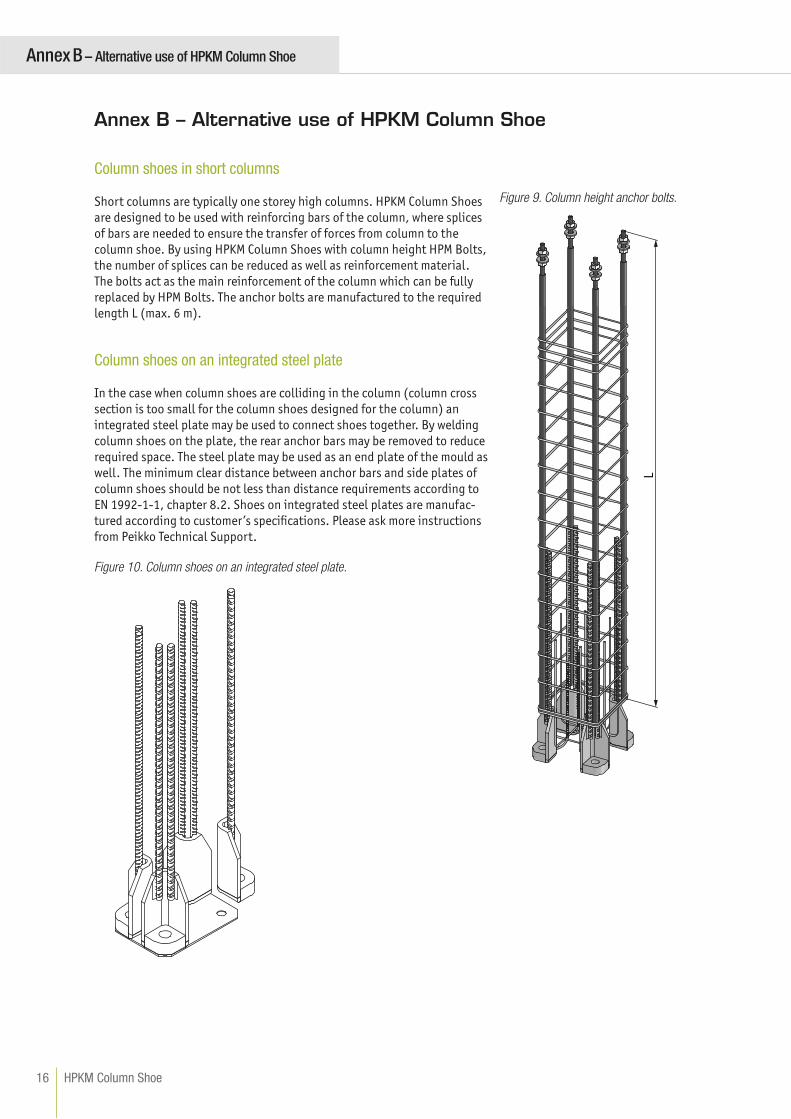
Column shoes in short columns
Short columns are typically one storey high columns. HPKM Column Shoes
are designed to be used with reinforcing bars of the column, where splices
of bars are needed to ensure the transfer of forces from column to the
column shoe. By using HPKM Column Shoes with column height HPM Bolts,
the number of splices can be reduced as well as reinforcement material.
The bolts act as the main reinforcement of the column which can be fully
replaced by HPM Bolts. The anchor bolts are manufactured to the required
length L (max. 6 m).
Column shoes on an integrated steel plate
In the case when column shoes are colliding in the column (column cross
section is too small for the column shoes designed for the column) an
integrated steel plate may be used to connect shoes together. By welding
column shoes on the plate, the rear anchor bars may be removed to reduce
required space. The steel plate may be used as an end plate of the mould as
well. The minimum clear distance between anchor bars and side plates of
column shoes should be not less than distance requirements according to
EN 1992-1-1, chapter 8.2. Shoes on integrated steel plates are manufac-
tured according to customer’s specifi cations. Please ask more instructions
from Peikko Technical Support.
Figure 10. Column shoes on an integrated steel plate.
L
Figure 9. Column height anchor bolts.
Annex B – Alternative use of HPKM Column Shoe
HPKM Column Shoe16
Annex B – Alternative use of HPKM Column Shoe
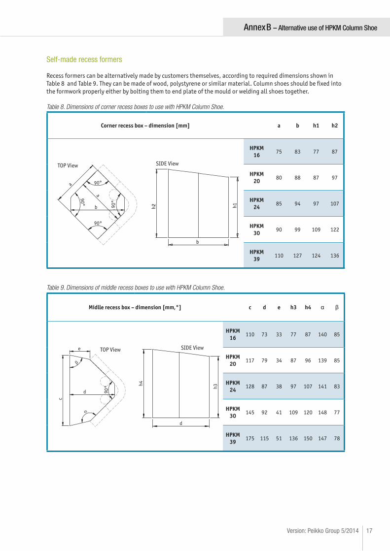
Self-made recess formers
Recess formers can be alternatively made by customers themselves, according to required dimensions shown in
Table 8 and Table 9. They can be made of wood, polystyrene or similar material. Column shoes should be fi xed into
the formwork properly either by bolting them to end plate of the mould or welding all shoes together.
Table 8. Dimensions of corner recess boxes to use with HPKM Column Shoe.
Corner recess box – dimension [mm] a b h1 h2
90
°
90
°
90°
90°
a
a
b
TOP View
h1
h2
b
SIDE View
HPKM
1675 83 77 87
HPKM
2080 88 87 97
HPKM
2485 94 97 107
HPKM
3090 99 109 122
HPKM
39110 127 124 136
Table 9. Dimensions of middle recess boxes to use with HPKM Column Shoe.
Midlle recess box – dimension [mm,°] c d e h3 h4 α β
c
d 90
°
e TOP View
h3
h4
d
SIDE View
HPKM
16110 73 33 77 87 140 85
HPKM
20117 79 34 87 96 139 85
HPKM
24128 87 38 97 107 141 83
HPKM
30145 92 41 109 120 148 77
HPKM
39175 115 51 136 150 147 78
17Version: Peikko Group 5/2014
Annex B – Alternative use of HPKM Column Shoe
INSTALL THE PRODUCT – PRECAST FACTORY
Identifi cation of the product
HPKM Column Shoes are available in standard models (16, 20, 24, 30 and 39) analogous to M-thread sizes of the
HPM Anchor Bolts. The model of column shoe can be identifi ed by the name in the label on the product and also
according to the color of the product. Color codes are shown in the table hereafter. Color codes of recess boxes are
corresponding to the color codes of HPKM Column Shoes.
HPKM Column Shoe with corresponding recess box.
Column Shoe Anchor Bolt Corner recess Middle recess Color code
HPKM 16 HPM 16 HPKM 16 CBOX HPKM 16 MBOX yellow
HPKM 20 HPM 20 HPKM 20 CBOX HPKM 20 MBOX blue
HPKM 24 HPM 24 HPKM 24 CBOX HPKM 24 MBOX gray
HPKM 30 HPM 30 HPKM 30 CBOX HPKM 30 MBOX green
HPKM 39 HPM 39 HPKM 39 CBOX HPKM 39 MBOX orange
Installation of the column choes
The HPKM Column Shoes are placed into the reinforcement of the column and fi xed through their base plates to
the end plate of the mould with recess boxes. Installation tolerance of column shoe in crosswise direction of the
column is ± 2 mm. Supplementary reinforcement must be placed at the area of column base, according to drawings
(Technical Manual Annex A). After casting the column, boxes are removed from shoes and voids are checked that
they are clean from concrete.
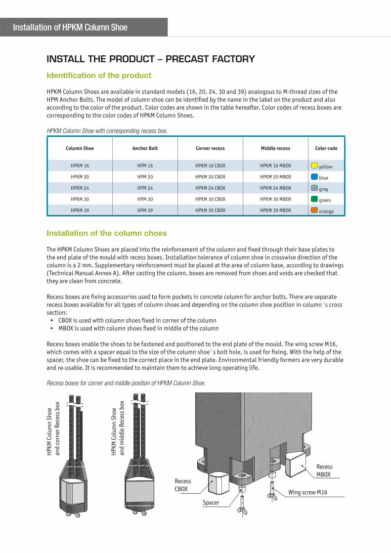
Recess boxes are fi xing accessories used to form pockets in concrete column for anchor bolts. There are separate
recess boxes available for all types of column shoes and depending on the column shoe position in column´s cross
section:
• CBOX is used with column shoes fi xed in corner of the column
• MBOX is used with column shoes fi xed in middle of the column
Recess boxes enable the shoes to be fastened and positioned to the end plate of the mould. The wing screw M16,
which comes with a spacer equal to the size of the column shoe`s bolt hole, is used for fi xing. With the help of the
spacer, the shoe can be fi xed to the correct place in the end plate. Environmental friendly formers are very durable
and re-usable. It is recommended to maintain them to achieve long operating life.
Recess boxes for corner and middle position of HPKM Column Shoe.
HPK
M C
olum
n S
hoe
and
corn
er R
eces
s bo
x
HPK
M C
olum
n S
hoe
and
mid
dle
Rec
ess
box
Recess
CBOX
Recess
MBOX
Spacer
Wing screw M16
Installation of HPKM Column Shoe
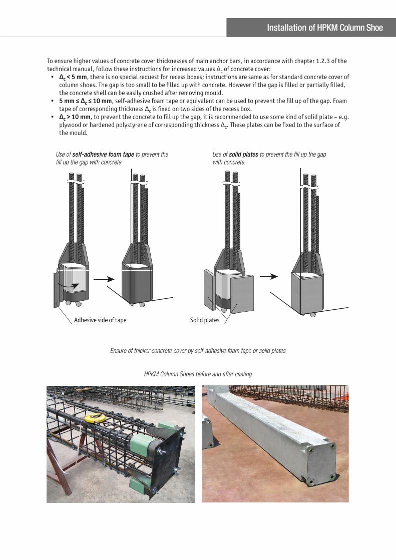
To ensure higher values of concrete cover thicknesses of main anchor bars, in accordance with chapter 1.2.3 of the
technical manual, follow these instructions for increased values Δc of concrete cover:
• Δc < 5 mm, there is no special request for recess boxes; instructions are same as for standard concrete cover of
column shoes. The gap is too small to be fi lled up with concrete. However if the gap is fi lled or partially fi lled,
the concrete shell can be easily crushed after removing mould.
• 5 mm ≤ Δc ≤ 10 mm, self-adhesive foam tape or equivalent can be used to prevent the fi ll up of the gap. Foam
tape of corresponding thickness Δc is fi xed on two sides of the recess box.
• Δc > 10 mm, to prevent the concrete to fi ll up the gap, it is recommended to use some kind of solid plate – e.g.
plywood or hardened polystyrene of corresponding thickness Δc. These plates can be fi xed to the surface of
the mould.
Use of self-adhesive foam tape to prevent the fi ll up the gap with concrete.
Use of solid plates to prevent the fi ll up the gap with concrete.
Ensure of thicker concrete cover by self-adhesive foam tape or solid plates
HPKM Column Shoes before and after casting
Adhesive side of tape Solid plates
Installation of HPKM Column Shoe
INSTALL THE PRODUCT – CONSTRUCTION SITE
Identifi cation of the product
HPKM Column Shoes are available in standard models (16, 20, 24, 30 and 39) analogous to HPM Anchor Bolts M-
thread sizes. The model of column shoe can be identifi ed by the name in the label on the product and also accord-
ing to the color of the product. Color codes are shown in the table hereafter.
HPKM Column Shoe color identifi cation
Column Shoe Color code Anchor Bolt Installation template
HPKM 16 yellow HPM 16 PPL 16
HPKM 20 blue HPM 20 PPL 20
HPKM 24 gray HPM 24 PPL 24
HPKM 30 green HPM 30 PPL 30
HPKM 39 orange HPM 39 PPL 39
Erection of precast column
1. To level precast concrete column
Before erecting the column, upper nuts and washers are removed from anchor bolts. Lower leveling nuts and wash-
ers are adjusted at the correct level. The column is erected directly on the pre-leveled washers and nuts.
In alternative method shims are placed between anchor bolts and adjusted at the proper level. Lower leveling nuts
must be leveled at least 5 mm under the top level of shims to secure that column will rest fi rst on the shims. This
method is recommended for heavier columns for easier and faster alignment of the column.
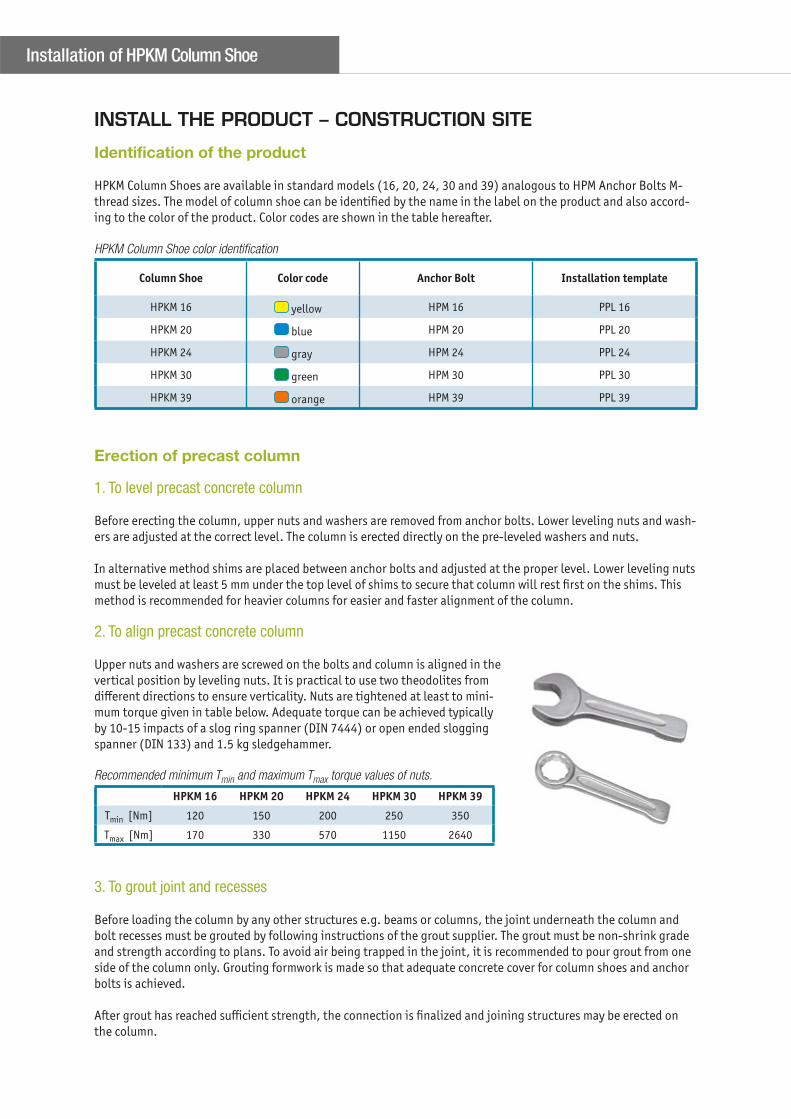
2. To align precast concrete column
Upper nuts and washers are screwed on the bolts and column is aligned in the
vertical position by leveling nuts. It is practical to use two theodolites from
diff erent directions to ensure verticality. Nuts are tightened at least to mini-
mum torque given in table below. Adequate torque can be achieved typically
by 10-15 impacts of a slog ring spanner (DIN 7444) or open ended slogging
spanner (DIN 133) and 1.5 kg sledgehammer.
Recommended minimum Tmin and maximum Tmax torque values of nuts.
HPKM 16 HPKM 20 HPKM 24 HPKM 30 HPKM 39
Tmin [Nm] 120 150 200 250 350
Tmax [Nm] 170 330 570 1150 2640
3. To grout joint and recesses
Before loading the column by any other structures e.g. beams or columns, the joint underneath the column and
bolt recesses must be grouted by following instructions of the grout supplier. The grout must be non-shrink grade
and strength according to plans. To avoid air being trapped in the joint, it is recommended to pour grout from one
side of the column only. Grouting formwork is made so that adequate concrete cover for column shoes and anchor
bolts is achieved.
After grout has reached suffi cient strength, the connection is fi nalized and joining structures may be erected on
the column.
Installation of HPKM Column Shoe
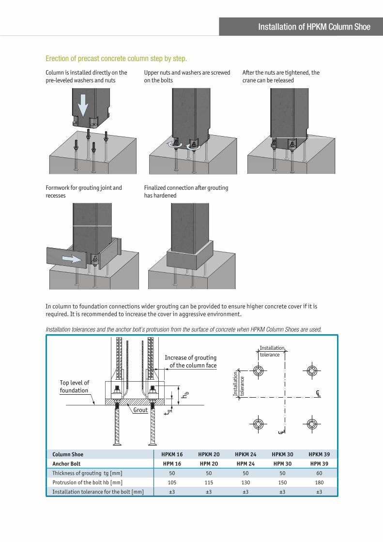
Formwork for grouting joint and
recesses
Finalized connection after grouting
has hardened
In column to foundation connections wider grouting can be provided to ensure higher concrete cover if it is
required. It is recommended to increase the cover in aggressive environment.
Installation tolerances and the anchor bolt`s protrusion from the surface of concrete when HPKM Column Shoes are used.
t g
hb
Top level of
foundation
Grout
Increase of grouting
of the column face
Installation
tolerance
Column Shoe HPKM 16 HPKM 20 HPKM 24 HPKM 30 HPKM 39
Anchor Bolt HPM 16 HPM 20 HPM 24 HPM 30 HPM 39
Thickness of grouting tg [mm] 50 50 50 50 60
Protrusion of the bolt hb [mm] 105 115 130 150 180
Installation tolerance for the bolt [mm] ±3 ±3 ±3 ±3 ±3
Column is installed directly on the
pre-leveled washers and nuts
Upper nuts and washers are screwed
on the bolts
After the nuts are tightened, the
crane can be released
Erection of precast concrete column step by step.
Installation of HPKM Column Shoe

Notes

Notes

PEIKKO GROUP CORPORATION
Peikko Group Corporation is a leading global supplier of concrete
connections and composite structures. Peikko’s innovative solutions
make the customers’ building process faster, easier and more reliable.
Peikko has subsidiaries in over 30 countries in Asia-Pacifi c, Europe,
the Middle East, and North America, with manufacturing operations
in 10 countries. Our aim is to serve our customers locally with leading
solutions in the fi eld in terms of quality, safety, and innovation.
Peikko is a family-owned and run company with over 1000
professionals. Peikko was founded in 1965 and is headquartered in
Lahti, Finland.