bending of column shoe connections - tests and results
TRANSCRIPT
Bending of column shoe connections -
tests and results
TR 067
September 2018
EOTA TR 067 2/19
©EOTA 2018
EOTA Technical Reports are developed as supporting reference documents to EOTA publications such as European Technical Approval Guidelines (ETAG) and European Assessment Documents (EAD), or other harmonised technical specifications. They can be used for technical assessments of construction products, notably when conducted by Technical Assessment Bodies (TAB) designated by European Members States in accordance to Regulation (EU) No. 305/2011 for issuing European Technical Assessments (ETA). EOTA Technical Reports detail aspects relevant for construction products such as design, execution and evaluation of tests, and express the common understanding of existing knowledge and experience of the Technical Assessment Bodies in EOTA at a particular point in time. They may give recommendations for product packaging, transport, storage, maintenance, replacement and repair. Where knowledge and experience is developing, especially through assessment work, such reports can be amended. Amendments of EOTA Technical Reports supersede the previous one. The reference title and language for this TR is English. The applicable rules of copyright refer to the document elaborated in and published by EOTA. This EOTA Technical Report has been elaborated by EOTA WG 20 - Structural Metallic Products and Ancillaries; convened by VTT and has been adopted by the EOTA Technical Board.
EOTA TR 067 3/19
©EOTA 2018
Contents
1 Scope of the TR ..............................................................................................................................4
2 Specific terms/symbols used in this TR .......................................................................................4
2.1 Specific terms 4
2.2 List of Symbols 4
3 Bending tests ..................................................................................................................................6
3.1 General 6
3.2 Bending stiffness test BRS 6 3.2.1 General .........................................................................................................................................6 3.2.2 Test arrangements .......................................................................................................................6
3.3 Bending resistance test BR 9
4 DETERMINATION OF BENDING STIFFNESS 10
4.1 Number of BRS tests 10
4.2 Stiffness of subzones 10
4.3 Bending stiffness comparison 10 4.3.1 General ...................................................................................................................................... 10 4.3.2 Stiffness of column A ................................................................................................................ 11 4.3.3 Stiffness of column B ................................................................................................................ 12
4 Initial tests: tensile resistance of column shoes ...................................................................... 13
5.1 Number of tests 13
5.2 Nominal yield resistance or yield strength of anchor bolts 13
5.3 Evaluation of bending test results 13
5 Initial tests: Shear resistance ..................................................................................................... 14
6.1 Test arrangements 14
6.2 Number of shear tests and criterion for shear resistance 15
6 Control tests: Air test TA ............................................................................................................ 16
7.1 Description of air tests 16
7.2 Criteria for air tests 16
7 Tests for calibration of temperature analysis ........................................................................... 17
8 Test report .................................................................................................................................... 18
9 Reference documents ................................................................................................................. 19
EOTA TR 067 4/19
©EOTA 2018
1 SCOPE OF THE TR
This Technical Report (TR) includes details the methods and criteria for assessing the performance of column shoes according to EAD 200102.
2 SPECIFIC TERMS/SYMBOLS USED IN THIS TR
2.1 Specific terms
Base plate Thick, horizontal steel plate provided with a vertical hole; fixed to a threaded anchor bolt by two nuts and two washers
Side plate Vertical, bent or straight steel plate(s) welded to the bottom plate
Anchor bar Vertical reinforcing bar welded to side plate(s)
Rear bar Partly vertical reinforcing bar, lower end bent, welded to side plate(s)
Top plate A thin, non-structural steel plate parallel to the base plate but above it, serves as a mould when the column is concreted
2.2 List of Symbols
(EI) bending stiffness
(EI)i bending stiffness of subzone i in numerical comparison, precast column
(EI)'i bending stiffness of subzone i in numerical comparison, cast-in-situ column
i,fF failure load in air test i
H vertical distance between transducers fixed to the top surface and soffit of test beam or horizontal
force in numerical comparison
Lc height of column in numerical comparison
Leff effective length to be used instead of l0 when designing the column with column shoes in
accordance with EN 1992-1-1
Lg,j measuring length of transducers in subzone j in bending test
Llap lap length
Lshoe height of column shoe zone
iM bending moment in the middle of subzone i in numerical comparison
tM theoretical yielding moment of column shoe connection
Mt,0 theoretical yielding moment of column shoe connection calculated using the actual yield
strength of the anchor bolts (mean value of test results) and the nominal strength of the
concrete
P point load
V shear force
Ve experimental shear resistance of connection in shear test
Vt theoretical shear resistance of connection in shear test
EOTA TR 067 5/19
©EOTA 2018
Zi name of subzone i
a horizontal distance in test arrangements
b horizontal distance in test arrangements
h depth of column element in bending and shear tests
ki flexibility factor according to EN 1992-1-1, Chapter 5.8.3.2, i = 1 or 2
kL experimental factor:
- if kL ≤ 1,10, kLl0 gives the effective length to be used instead of l0 when designing the
columns in accordance with EN 1992-1-1
- if kL > 1,10, the connection is assumed to be hinged in design and effective length l0 specified in
EN 1992-1-1 is used as such
kn deviation factor
ks calibration factor for shear resistance
l0 Euler's buckling length (effective length in EN 1992-1-1)
m number of straight anchor bars or number of measured subzones outside column shoe zone
mk characteristic value of mi-values, i = 1,....,n (n is number of the tests)
mm mean value of mi-values, i = 1,....,n (n is number of the tests)
n number of active column shoes, number of tests, number of subzones Zi in column shoe zone
sm standard deviation of mi-values, i = 1,...., n (n is number of the tests)
u axial contraction of subzone Zi in bending test
ui measured axial contraction of subzone Zi in bending test, soffit
v axial elongation in bending test
vi measured axial elongation of subzone Zi in bending test, soffit
vref deflection of cast-in-situ column in numerical comparison
vshoe deflection of precast column in numerical comparison
x longitudinal coordinate
d experimental stiffness factor ≤ d,0
d,0 stiffness factor ≤ 1,00 given by the producer and used for the design of the test specimens
i curvature of column cross-section
EOTA TR 067 6/19
©EOTA 2018
3 BENDING TESTS
3.1 General
Tests are carried out to verify the design rules for bending as well as to determine the bending stiffness of the column shoe connection.
3.2 Bending stiffness test BRS
3.2.1 General
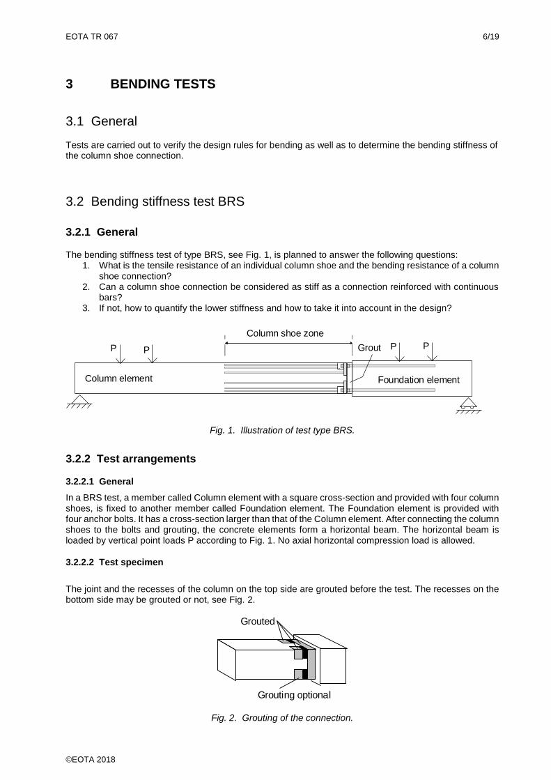
The bending stiffness test of type BRS, see Fig. 1, is planned to answer the following questions: 1. What is the tensile resistance of an individual column shoe and the bending resistance of a column
shoe connection? 2. Can a column shoe connection be considered as stiff as a connection reinforced with continuous
bars? 3. If not, how to quantify the lower stiffness and how to take it into account in the design?
PP P P
Column shoe zone
Grout
Column element Foundation element
Fig. 1. Illustration of test type BRS.
3.2.2 Test arrangements
3.2.2.1 General
In a BRS test, a member called Column element with a square cross-section and provided with four column shoes, is fixed to another member called Foundation element. The Foundation element is provided with four anchor bolts. It has a cross-section larger than that of the Column element. After connecting the column shoes to the bolts and grouting, the concrete elements form a horizontal beam. The horizontal beam is loaded by vertical point loads P according to Fig. 1. No axial horizontal compression load is allowed.
3.2.2.2 Test specimen
The joint and the recesses of the column on the top side are grouted before the test. The recesses on the bottom side may be grouted or not, see Fig. 2.
Grouted
Grouting optional
Fig. 2. Grouting of the connection.
EOTA TR 067 7/19
©EOTA 2018
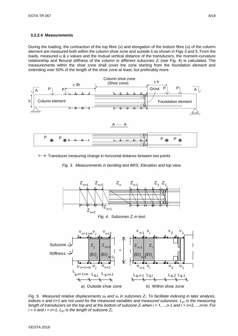
After the grout has hardened, the jointed horizontal specimen is placed on supports and loaded vertically with concentrated loads as shown in Fig. 3. The number of the concentrated loads can be freely chosen. The aim is to create a nearly constant bending moment in the mid-part of the test specimen where the curvature is measured. This is achieved by placing the concentrated loads symmetrically. The basic properties for the test specimen are summarized in Table 1. Table 1. Properties of test specimen.
Column element
- Length Minimum length is determined by two conditions: 1. The constant moment zone must be so long that the stiffness within
and outside the column shoe zone can reliably be determined 2. The loads must be so far from the supports that the bending
moment can be increased until the connection fails.
- Cross-section Minimum allowable when four column shoes of the considered type and size are used in the connection
- Strength of concrete Of the same order as the minimum allowable for the considered column shoe
- Main reinforcement Able to carry bending moment d,0 Mt,0 where Mt,0 is the bending resistance of the connection calculated using the actual yield strength of the anchor bolts (mean value of test results) and the nominal strength of the concrete.
d,0 ≤ 1,00 is a stiffness factor given by the producer before designing the test specimens
- Shear reinforcement The column shoe zone reinforced according to the manufacturer's instructions, elsewhere the test result is not sensitive to the shear reinforcement which may be designed to prevent shear failure in the test and to meet the requirements for minimum reinforcement
- Lifting hooks or inserts Designed in such a way that they do not affect either the measured bending stiffness or the bending resistance
Foundation element The cross-section, strength of the concrete and the reinforcement to be so chosen that the anchorage failure of the anchor bolts and the failure of the foundation element itself can be excluded in the test.
Connection The strength of the jointing mortar at least the lowest specified in the manufacturer's instructions. The recesses on the bottom side may be not grouted, see Fig. 6. The torque applied to the nuts according to the manufacturer's instructions.
3.2.2.3 Loads
The test specimen is loaded vertically by hydraulic actuators in such a way that the bending moment due to the actuator loads and loading equipment is constant over the length within which the horizontal differential displacements, see Chapter 3.2.2.4, are measured. The position of the concentrated load shall be chosen in such a way that the requirements presented in Fig. 7 are met. The loads are increased stepwise, until 40 – 60% of the nominal bending resistance of the anchor bolt connection without grouting is achieved. Thereafter, the loads are reduced stepwise back to zero or close to zero. This load cycle is carried out 3 – 5 times before increasing the loads stepwise until failure. The loads and displacements are measured and recorded at each load step.
EOTA TR 067 8/19
©EOTA 2018
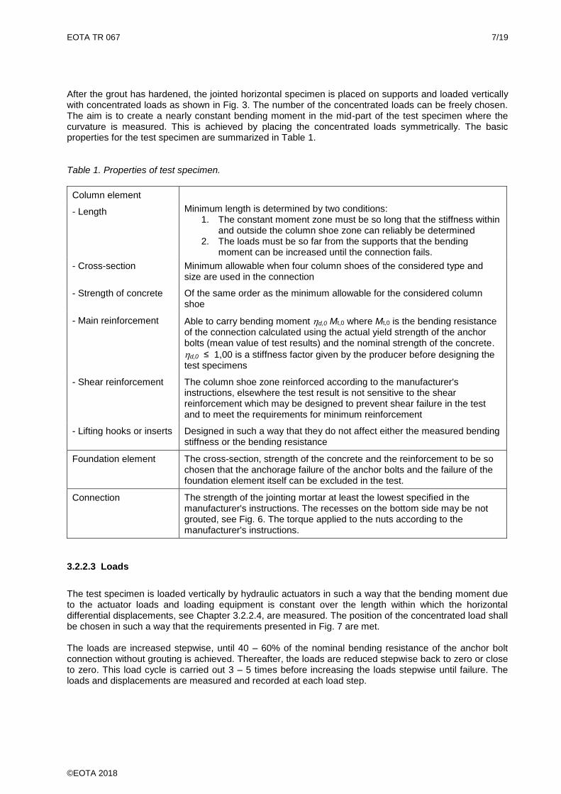
3.2.2.4 Measurements
During the loading, the contraction of the top fibre (v) and elongation of the bottom fibre (u) of the column element are measured both within the column shoe zone and outside it as shown in Figs 3 and 5. From the loads, measured u & v values and the mutual vertical distance of the transducers, the moment-curvature relationship and flexural stiffness of the column in different subzones Zi (see Fig. 4) is calculated. The measurements within the shoe zone shall cover the zone starting from the foundation element and extending over 50% of the length of the shoe zone at least, but preferably more.
A A
Transducer measuring change in horizontal distance between two points
PA AP P P
Column shoe zone (Shoe zone)
Grout
P P P P
Column element Foundation elementh
> 3h> h
Fig. 3. Measurements in bending test BRS. Elevation and top view.
Z2
Zn-1
Z1
Zn
Zn+1
Zn+2
Zn+3
Zn+4
Fig. 4. Subzones Zi in test.
H
n-1u
g,n+1+mL
g,jL g,n+2Lg,n-1L g,iL g,2L g,1L
iu
2u
1u
n-1v
iv
2v
1v
a) Outside shoe zone b) Within shoe zone
n+2v
jv
n+1+mv
n+2u
ju
n+1+mu
Zi
Zj
Zn+2 Z
n-1
i(EI)
n-1(EI)
n+2(EI)
j(EI)
Subzone
Stiffness
Fig. 5. Measured relative displacements uk and vk in subzones Zi. To facilitate indexing in later analysis, indices n and n+1 are not used for the measured variables and measured subzones. Lg,i is the measuring length of transducers on the top and at the bottom of subzone Zi when i = 1,…,n-1 and i = n+2,…,n+m. For i = n and i = n+1, Lg,i is the length of subzone Zi.
EOTA TR 067 9/19
©EOTA 2018
3.3 Bending resistance test BR
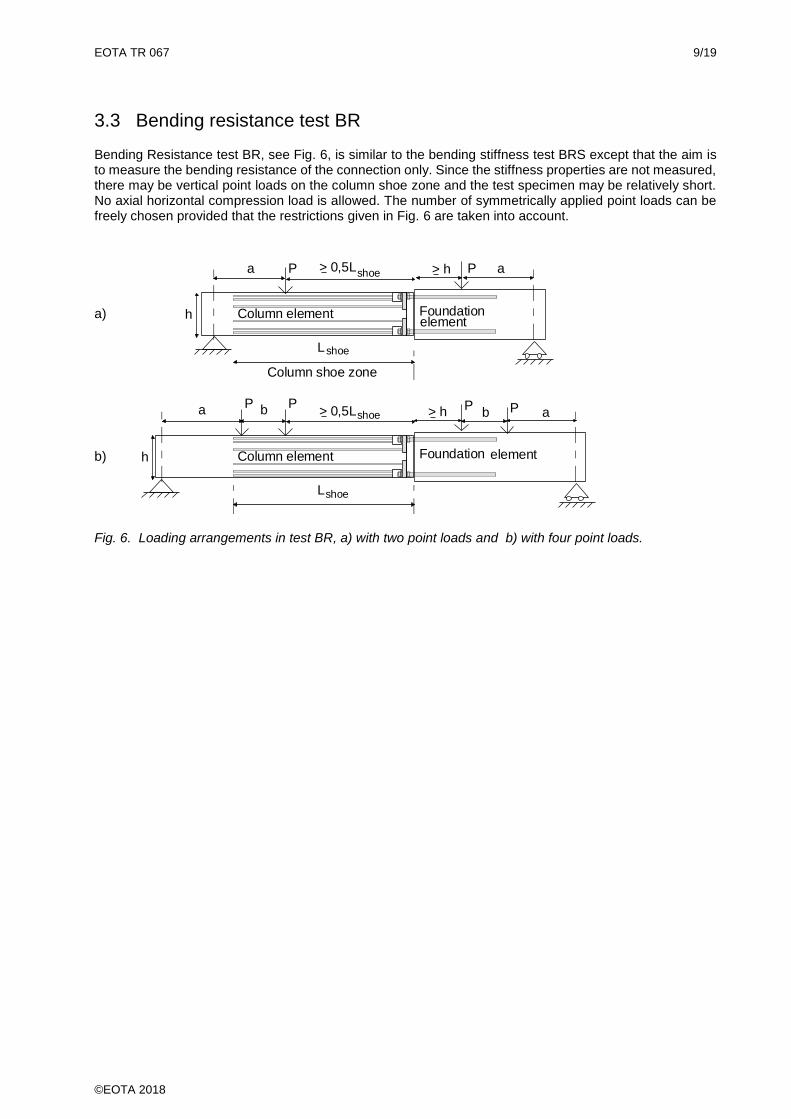
Bending Resistance test BR, see Fig. 6, is similar to the bending stiffness test BRS except that the aim is to measure the bending resistance of the connection only. Since the stiffness properties are not measured, there may be vertical point loads on the column shoe zone and the test specimen may be relatively short. No axial horizontal compression load is allowed. The number of symmetrically applied point loads can be freely chosen provided that the restrictions given in Fig. 6 are taken into account.
P
Column elementelement
Column shoe zone
Foundationa)
b)
L
> 0,5Lshoe > h aa
P
Column element elementFoundation
L
> 0,5L > h ba
P
PPshoeb aP
shoe
shoe
h
h
Fig. 6. Loading arrangements in test BR, a) with two point loads and b) with four point loads.
EOTA TR 067 10/19
©EOTA 2018
4 4 DETERMINATION OF BENDING STIFFNESS
4.1 Number of BRS tests
For each column shoe type (family), two tests of type BRS are performed, one with the smallest and one with the largest column shoe.
4.2 Stiffness of subzones
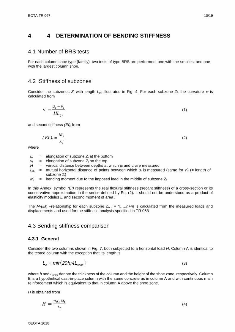
Consider the subzones Zi with length Lg,i illustrated in Fig. 4. For each subzone Zi, the curvature i is calculated from
i,g
iii
HL
vu −= (1)
and secant stiffness (EI)i from
i
ii
M)EI(
= (2)
where ui = elongation of subzone Zi at the bottom vi = elongation of subzone Zi on the top H = vertical distance between depths at which ui and vi are measured Lg,i = mutual horizontal distance of points between which ui is measured (same for vi) (= length of
subzone Zi) Mi = bending moment due to the imposed load in the middle of subzone Zi
In this Annex, symbol (EI) represents the real flexural stiffness (secant stiffness) of a cross-section or its conservative approximation in the sense defined by Eq. (2). It should not be understood as a product of elasticity modulus E and second moment of area I. The M-(EI) –relationship for each subzone Zi, i = 1,…,n+m is calculated from the measured loads and displacements and used for the stiffness analysis specified in TR 068
4.3 Bending stiffness comparison
4.3.1 General
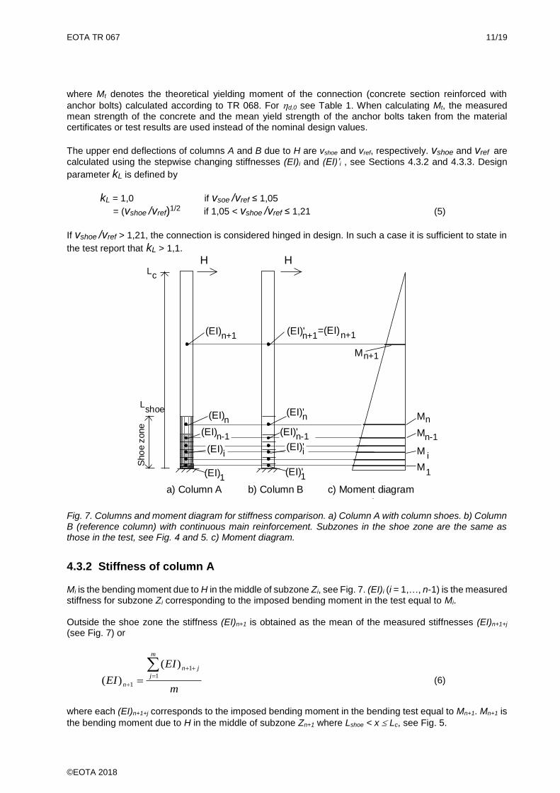
Consider the two columns shown in Fig. 7, both subjected to a horizontal load H. Column A is identical to the tested column with the exception that its length is
shoec L4;h20minL = (3)
where h and Lshoe denote the thickness of the column and the height of the shoe zone, respectively. Column B is a hypothetical cast-in-place column with the same concrete as in column A and with continuous main reinforcement which is equivalent to that in column A above the shoe zone. H is obtained from
𝐻 =𝜂𝑑,0𝑀𝑡
𝐿𝑐 (4)
EOTA TR 067 11/19
©EOTA 2018
where Mt denotes the theoretical yielding moment of the connection (concrete section reinforced with
anchor bolts) calculated according to TR 068. For d,0 see Table 1. When calculating Mt, the measured mean strength of the concrete and the mean yield strength of the anchor bolts taken from the material certificates or test results are used instead of the nominal design values.
The upper end deflections of columns A and B due to H are vshoe and vref, respectively. vshoe and vref are
calculated using the stepwise changing stiffnesses (EI)i and (EI)’i , see Sections 4.3.2 and 4.3.3. Design
parameter kL is defined by
kL = 1,0 if vsoe /vref ≤ 1,05
= (vshoe /vref)1/2 if 1,05 < vshoe /vref ≤ 1,21 (5)
If vshoe /vref > 1,21, the connection is considered hinged in design. In such a case it is sufficient to state in
the test report that kL > 1,1.
(EI)1
a) Column A
(EI)i
Sho
e z
one
b) Column B
(EI)n-1
Lc
(EI)n
(EI)n+1
(EI)'1
(EI)'i
(EI)'n-1
(EI)'n
(EI)'n+1
H H
=(EI)n+1
M1
Mi
Mn-1
Mn
Mn+1
c) Moment diagram
Lshoe
Fig. 7. Columns and moment diagram for stiffness comparison. a) Column A with column shoes. b) Column B (reference column) with continuous main reinforcement. Subzones in the shoe zone are the same as those in the test, see Fig. 4 and 5. c) Moment diagram.
4.3.2 Stiffness of column A
Mi is the bending moment due to H in the middle of subzone Zi, see Fig. 7. (EI)i (i = 1,…, n-1) is the measured stiffness for subzone Zi corresponding to the imposed bending moment in the test equal to Mi. Outside the shoe zone the stiffness (EI)n+1 is obtained as the mean of the measured stiffnesses (EI)n+1+j (see Fig. 7) or
m
EI
EI
m
j
jn
n
=
++
+ =1
1
1
)(
)( (6)
where each (EI)n+1+j corresponds to the imposed bending moment in the bending test equal to Mn+1. Mn+1 is
the bending moment due to H in the middle of subzone Zn+1 where Lshoe < x Lc, see Fig. 5.
EOTA TR 067 12/19
©EOTA 2018
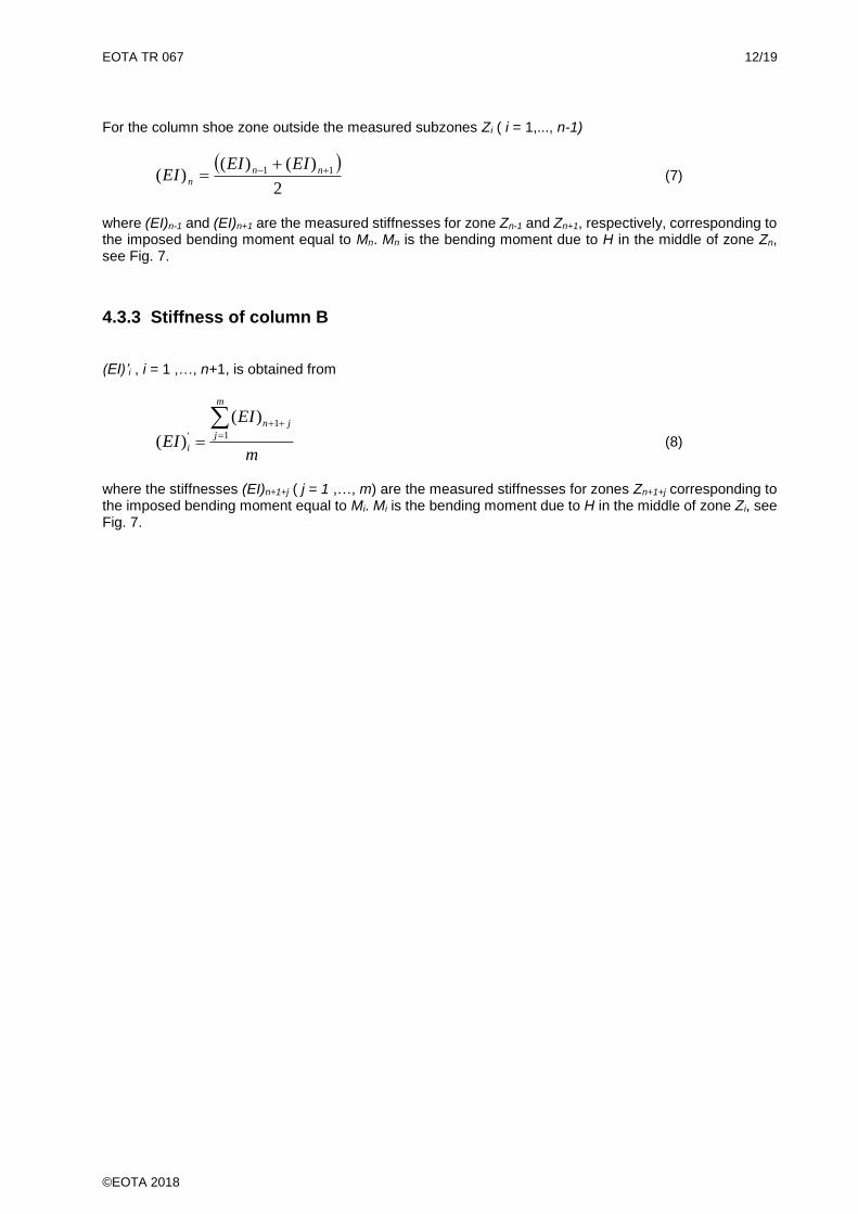
For the column shoe zone outside the measured subzones Zi ( i = 1,..., n-1)
( )2
)()()( 11 +− +
= nnn
EIEIEI (7)
where (EI)n-1 and (EI)n+1 are the measured stiffnesses for zone Zn-1 and Zn+1, respectively, corresponding to the imposed bending moment equal to Mn. Mn is the bending moment due to H in the middle of zone Zn, see Fig. 7.
4.3.3 Stiffness of column B
(EI)’i , i = 1 ,…, n+1, is obtained from
m
EI
EI
m
j
jn
i
=
++
=1
1
'
)(
)( (8)
where the stiffnesses (EI)n+1+j ( j = 1 ,…, m) are the measured stiffnesses for zones Zn+1+j corresponding to the imposed bending moment equal to Mi. Mi is the bending moment due to H in the middle of zone Zi, see Fig. 7.
EOTA TR 067 13/19
©EOTA 2018
5 INITIAL TESTS: TENSILE RESISTANCE OF COLUMN SHOES
5.1 Number of tests
The tensile resistance of the column shoes is verified indirectly by bending tests. In addition to the two (smallest and largest size) BRS tests carried out for bending stiffness comparison, at least three tests of type BR in the case with five sizes (smallest, middle and largest size), see 3.3, are carried out for each type of column shoe.
5.2 Nominal yield resistance or yield strength of anchor bolts
The nominal yield resistance or yield strength of the anchor bolts is determined as the mean yield resistance or mean yield strength, respectively, obtained from three tests/one type of anchor bolt which belong to the same batch and have the same material as the bolts in a bending or shear test. The 0,2% yield limit is used as yielding criterion if there is no clear yielding point.
5.3 Evaluation of bending test results
The test results are evaluated in families within which the type of the column shoe and anchor bolt is the same. Assume that the experimental and theoretical bending resistances for a family are Me,i and Mt,i, respectively, where i = 1,...,n (n ≥ 5). The theoretical resistances are calculated in accordance with Section
3.3.2 of TR 068 assuming that the stiffness factor d ≤ 1,00 and using the measured strength of the concrete and the measured yield resistance of the steel in the anchor bolt, see 5.2. The mean mm, standard deviation sm and characteristic value
mnmk skmm −= (9)
are calculated from values
i,t
i,e
iM
Mm = , i = 1,..., n (10)
and the value of kn is taken from EN 1990, Table D1.
For the considered family, the stiffness factor d for the design, see Section 3.3.2 of TR 068, is obtained from
𝜂𝑑 = min{𝑚𝑘; 𝜂𝑑,0} (11)
EOTA TR 067 14/19
©EOTA 2018
6 INITIAL TESTS: SHEAR RESISTANCE
6.1 Test arrangements
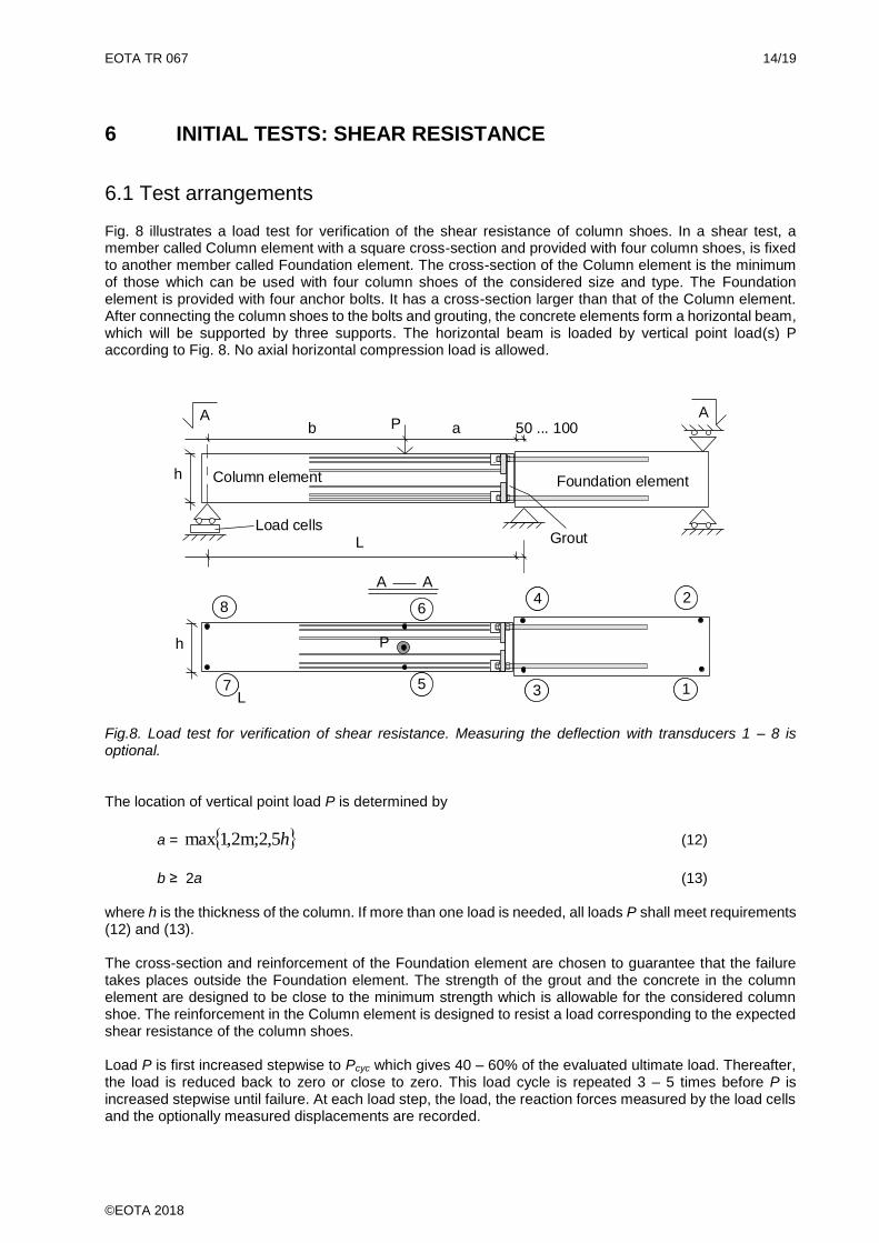
Fig. 8 illustrates a load test for verification of the shear resistance of column shoes. In a shear test, a member called Column element with a square cross-section and provided with four column shoes, is fixed to another member called Foundation element. The cross-section of the Column element is the minimum of those which can be used with four column shoes of the considered size and type. The Foundation element is provided with four anchor bolts. It has a cross-section larger than that of the Column element. After connecting the column shoes to the bolts and grouting, the concrete elements form a horizontal beam, which will be supported by three supports. The horizontal beam is loaded by vertical point load(s) P according to Fig. 8. No axial horizontal compression load is allowed.
A A
A AP
Grout
P
Column element Foundation element
ab
L
50 ... 100
Load cells
L
14
1315
1618
17
12
11
h
h
Fig.8. Load test for verification of shear resistance. Measuring the deflection with transducers 1 – 8 is optional. The location of vertical point load P is determined by
a = h5,2;m2,1max (12)
b ≥ 2a (13)
where h is the thickness of the column. If more than one load is needed, all loads P shall meet requirements (12) and (13). The cross-section and reinforcement of the Foundation element are chosen to guarantee that the failure takes places outside the Foundation element. The strength of the grout and the concrete in the column element are designed to be close to the minimum strength which is allowable for the considered column shoe. The reinforcement in the Column element is designed to resist a load corresponding to the expected shear resistance of the column shoes. Load P is first increased stepwise to Pcyc which gives 40 – 60% of the evaluated ultimate load. Thereafter, the load is reduced back to zero or close to zero. This load cycle is repeated 3 – 5 times before P is increased stepwise until failure. At each load step, the load, the reaction forces measured by the load cells and the optionally measured displacements are recorded.
EOTA TR 067 15/19
©EOTA 2018
6.2 Number of shear tests and criterion for shear resistance
Two tests are carried out for each column shoe family, one for the smallest and one for the largest column shoe in the family. In both cases, the column cross-section is the minimum applicable to the considered column shoe. In each test, the shear force of the connection observed at failure, Ve, shall meet the requirement
Ve ≥ ks Vt (14)
where Vt is the sum of the shear resistances of two column shoes calculated according to Section 3.3.4.4
of TR 068 using M2 = 1,0 and the yield strength of the anchor bolt measured as specified in 5.2. ks is a
calibration factor ≤ 1,0 chosen for each product family in such a way that the results from both shear tests meet requirement (14). The strength of the base plate is taken from the certificates of compliance (inspection certificate 3.1 in accordance with EN 10204).
EOTA TR 067 16/19
©EOTA 2018
7 CONTROL TESTS: AIR TEST TA
7.1 Description of air tests
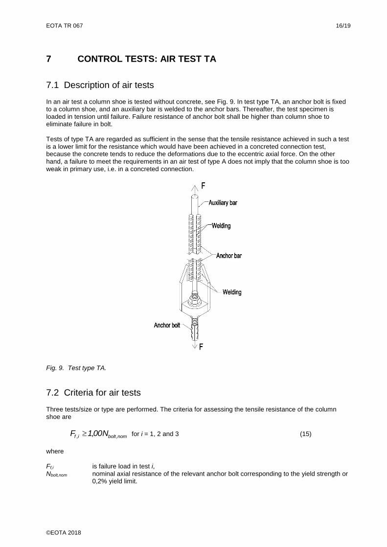
In an air test a column shoe is tested without concrete, see Fig. 9. In test type TA, an anchor bolt is fixed to a column shoe, and an auxiliary bar is welded to the anchor bars. Thereafter, the test specimen is loaded in tension until failure. Failure resistance of anchor bolt shall be higher than column shoe to eliminate failure in bolt. Tests of type TA are regarded as sufficient in the sense that the tensile resistance achieved in such a test is a lower limit for the resistance which would have been achieved in a concreted connection test, because the concrete tends to reduce the deformations due to the eccentric axial force. On the other hand, a failure to meet the requirements in an air test of type A does not imply that the column shoe is too weak in primary use, i.e. in a concreted connection.
Fig. 9. Test type TA.
7.2 Criteria for air tests
Three tests/size or type are performed. The criteria for assessing the tensile resistance of the column shoe are
nom,bolti,f N00,1F for i = 1, 2 and 3 (15)
where Ff,i is failure load in test i, Nbolt,nom nominal axial resistance of the relevant anchor bolt corresponding to the yield strength or
0,2% yield limit.
EOTA TR 067 17/19
©EOTA 2018
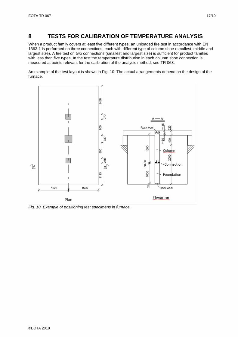
8 TESTS FOR CALIBRATION OF TEMPERATURE ANALYSIS
When a product family covers at least five different types, an unloaded fire test in accordance with EN 1363-1 is performed on three connections, each with different type of column shoe (smallest, middle and largest size). A fire test on two connections (smallest and largest size) is sufficient for product families with less than five types. In the test the temperature distribution in each column shoe connection is measured at points relevant for the calibration of the analysis method, see TR 068. An example of the test layout is shown in Fig. 10. The actual arrangements depend on the design of the furnace.
Fig. 10. Example of positioning test specimens in furnace.
EOTA TR 067 18/19
©EOTA 2018
9 TEST REPORT
The test report shall include all information about the tests necessary to assess the performance of the column shoe connections when subjected to mechanical loads and/or fire behaviour. It shall be included in the construction dossier.
EOTA TR 067 19/19
©EOTA 2018
10 REFERENCE DOCUMENTS
As far as no edition date is given in the list of thereafter, the publication in its current version is of relevance. EAD 200102-00-0302 Evaluation Assessment Document of Column Shoes
EN 1363-1 Fire resistance tests. Part 1: General Requirements
EN 1992-1-1 Eurocode 2: Design of concrete structures - Part 1-1: General rules and rules for buildings
EN 1992-1-2 Eurocode 2: Design of concrete structures - Part 1-2: General rules - Structural fire design
EN 1993-1-1 Eurocode 3: Design of steel structures - Part 1-1: General rules and rules for buildings
EN 1993-1-2 Eurocode 3: Design of steel structures - Part 1-2: General rules - Structural fire design
EN 1993-1-8 Eurocode 3: Design of steel structures - Part 1-8: Design of joints
EN 1993-1-8 Eurocode 3: Design of steel structures. Part 1-8: Design of joints
Technical Report TR 068 Calculation methods for column shoe connections