column shoe system - events.pfeifer.info
TRANSCRIPT

Column Shoe SystemInstallation and assembly instructions

2 © 2020 Copyright PFEIFER, 87700 Memmingen / Technical modifications and errors excepted. Date 08/2020Column Shoe System – installation
Installation
System description
Installation tolerances
Figure 1
Figure 2 Figure 3
Table 1: Column Shoe System colour coding
Type Colour
PCC-16 Sulphur yellow
PCC-20 Light blue
PCC-24 Silver grey
PCC-30-1 Emerald green
PCC-30-2 Pure white
PCC-36 Flame red
PCC-39-1 Water blue
PCC-39-2 Sun yellow
The Column Shoe System is intended for the prop-free assembly and rigid connection of columns to columns, columns to founda-tions and columns to beams.This bolted connection produces an immediate rigid connection; additional supports are thus unnecessary.
The PCC Column Shoes are ideally installed with the corresponding retaining bushes/positioning sockets and moulding inserts (fig. 1). This ensures that the column shoes, once in place, cannot shift during the concreting. The manufacture of congruent templates on site (fig. 2) for
column shoes and foundation anchors increases the imple-mentation safety. Before commencing with the assem-bly, the reference dimensions specified by the planner and shown in figure 3 must be checked to ensure that they are correct.
Table 2: Installation tolerances
Type Hole Ø [mm]
Bolt Ø [mm]
Max. eccentricity [mm]
PCC-16 28 16/20 ± 6,0/4,0PCC-20 30 20/24 ± 5,0/3,0PCC-24 35 24 ± 5,5PCC-30-1 40 30 ± 5,0PCC-30-2 45 30/36 ± 7,5/4,5PCC-36 53 36/39 ± 8,5/7,0PCC-39-1 55 36/39 ± 9,5/8,0PCC-39-2 55 39/42 ± 8,0/6,5
Moulding insert
Retaining bush
Positioning socket
Fixing screw
3© 2020 Copyright PFEIFER, 87700 Memmingen / Technical modifications and errors excepted. Date 08/2020 Column Shoe System – installation
Installation
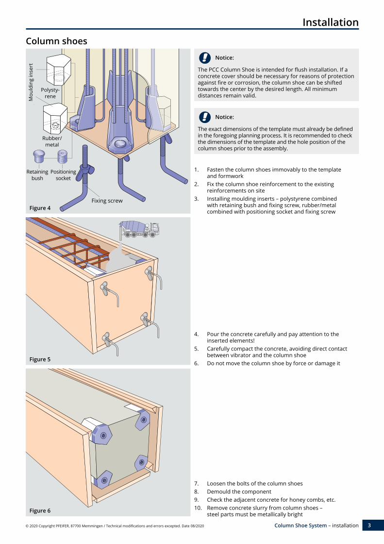
Column shoes
Figure 4
Figure 5
Figure 6
Notice:
The PCC Column Shoe is intended for flush installation. If a concrete cover should be necessary for reasons of protection against fire or corrosion, the column shoe can be shifted towards the center by the desired length. All minimum distances remain valid.
1. Fasten the column shoes immovably to the template and formwork
2. Fix the column shoe reinforcement to the existing reinforcements on site
3. Installing moulding inserts – polystyrene combined with retaining bush and fixing screw, rubber/metal combined with positioning socket and fixing screw
4. Pour the concrete carefully and pay attention to the inserted elements!
5. Carefully compact the concrete, avoiding direct contact between vibrator and the column shoe
6. Do not move the column shoe by force or damage it
7. Loosen the bolts of the column shoes8. Demould the component9. Check the adjacent concrete for honey combs, etc.10. Remove concrete slurry from column shoes –
steel parts must be metallically bright
Notice:
The exact dimensions of the template must already be defined in the foregoing planning process. It is recommended to check the dimensions of the template and the hole position of the column shoes prior to the assembly.
Retaining bush
Positioning socket
Fixing screw
Mou
ldin
g in
sert
Polysty-rene
Rubber/ metal
4 © 2020 Copyright PFEIFER, 87700 Memmingen / Technical modifications and errors excepted. Date 08/2020Column Shoe System – installation
Installation
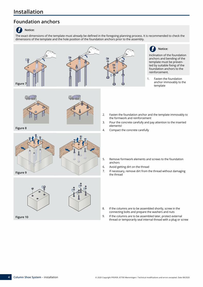
Foundation anchors
Notice:
Inclination of the foundation anchors and bending of the template must be preven-ted by suitable fixing of the foundation anchors to the reinforcement.
Notice:
The exact dimensions of the template must already be defined in the foregoing planning process. It is recommended to check the dimensions of the template and the hole position of the foundation anchors prior to the assembly.
1. Fasten the foundation anchor immovably to the template
2. Fasten the foundation anchor and the template immovably to the formwork and reinforcement
3. Pour the concrete carefully and pay attention to the inserted elements!
4. Compact the concrete carefully
5. Remove formwork elements and screws to the foundation anchors
6. Avoid getting dirt on the thread7. If necessary, remove dirt from the thread without damaging
the thread
8. If the columns are to be assembled shortly, screw in the connecting bolts and prepare the washers and nuts
9. If the columns are to be assembled later, protect external thread or temporarily seal internal thread with a plug or screw
Figure 7
Figure 8
Figure 9
Figure 10

5© 2020 Copyright PFEIFER, 87700 Memmingen / Technical modifications and errors excepted. Date 08/2020 Column Shoe System – installation
Assembly
Column
Figure 15
Figure 13
Figure 17
Notice:
The upper nuts and washers should only be removed from the connecting bolts/foundation anchors shortly before mounting the columns and should be stored in a suitable place nearby.
Notice:
It is recommended to lock the two nuts against each other beforehand to facilitate the screwing-in of the PVB/PGV con-necting bolts. Make sure they are screwed in to a minimum screw-in depth of 1.5 • thread diameter!
4. Completely remove the moulding inserts from the column (figure 12)
5. Remove all interfering parts and dirt in the region of the bolts
8. Screw the nuts and washers onto the bolts
9. Tighten the nuts hand-tight
1. Remove the upper nuts and washers
2. Adjust the lower nuts and washers to the target size f (see Table 3)
3. Optional placement of a steel package with dimension f in the middle of the column
11. Tighten nuts with an impact wrench – 10 blows with a 2 kg hammer
12. Detach the column from the crane
10. Bring the column into the perpendicular position
6. Prepare suitable assembly materials
7. Lift the column onto the bolts
13. Demould the lower area of the column
14. Mix the grouting material according to the manu-facturer‘s specifications and fill the recesses and intermediate space. a) Largest grain 5 mm b) Non-flammable A1 c) Swelling d) Minimum strength >
column concrete strength grade
Table 3: Limit sizes
Type Possible joint height f [mm]
Protrusion Ü [mm]
PCC-16 25–50 100PCC-20 30–50 110PCC-24 35–50 120PCC-30-1 40–60 140PCC-30-2 40–60 140PCC-36 50–70 170PCC-39-1 50–70 170PCC-39-2 50–70 170
Figure 12
Figure 14
Figure 11
Figure 16
optional

International
Sales
+49 (0) 83 31-937-231
Technical Support
+49 (0) 83 31-937-345
www.pfeifer.info/concrete-inserts 08.2
0 AB