how to successfully implement reliability physics analysis ... dfr conference/presentati… · −3...
TRANSCRIPT
9000 Virginia Manor Rd Ste 290, Beltsville MD 20705 | 301-474-0607 | www.dfrsolutions.com
How to Successfully Implement Reliability Physics Analysis
Standard SAE J3168 in Your Supply Chain
March 26, 2019Jim McLeish & Lloyd Condra - DfR Solutions
9000 Virginia Manor Rd Ste 290, Beltsville MD 20705 | 301-474-0607 | www.dfrsolutions.com
Copyright of DfR Solutions 2019
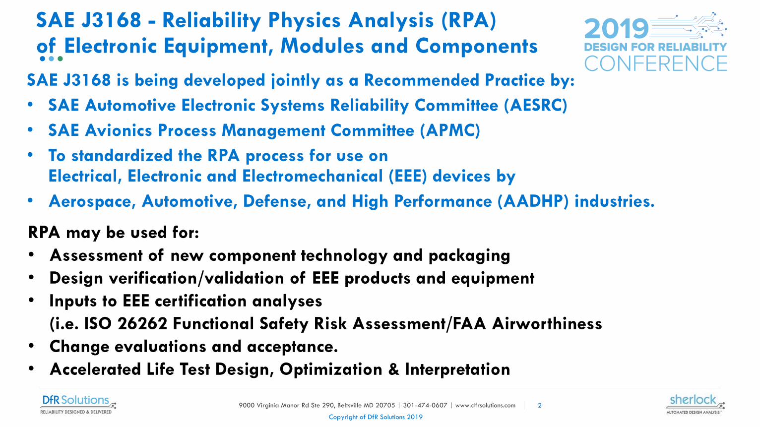
SAE J3168 is being developed jointly as a Recommended Practice by:
• SAE Automotive Electronic Systems Reliability Committee (AESRC)
• SAE Avionics Process Management Committee (APMC)
• To standardized the RPA process for use on Electrical, Electronic and Electromechanical (EEE) devices by
• Aerospace, Automotive, Defense, and High Performance (AADHP) industries.
SAE J3168 - Reliability Physics Analysis (RPA)of Electronic Equipment, Modules and Components
RPA may be used for:
• Assessment of new component technology and packaging
• Design verification/validation of EEE products and equipment
• Inputs to EEE certification analyses
(i.e. ISO 26262 Functional Safety Risk Assessment/FAA Airworthiness
• Change evaluations and acceptance.
• Accelerated Life Test Design, Optimization & Interpretation
2

9000 Virginia Manor Rd Ste 290, Beltsville MD 20705 | 301-474-0607 | www.dfrsolutions.com
Copyright of DfR Solutions 2019
• RPA is a science based, engineering discipline that:
− Leverages knowledge of material properties and failure mechanisms to identify failure risks, predict reliability/durability & improve design robustness
− Combines failure mechanism models developed by Physics-of-Failure (PoF) research with stress analysis of dynamic lifetime load profiles
› To calculate design & application specific durability life & likelihood of failure (i.e. Reliability) over time
SAE J3168 - Reliability Physics Analysis (RPA)
of Electronic Equipment, Modules and Components
−Performs durability simulations & models in a Computer Aided Engineering (CAE) environment
−Uses stress-strength analysis and the material science principle of stress driven damage accumulation in materials
− Integrates reliability-durability optimization into the EEE design process
3

9000 Virginia Manor Rd Ste 290, Beltsville MD 20705 | 301-474-0607 | www.dfrsolutions.com
Copyright of DfR Solutions 2019
• Situational Awareness
• High Resolution Mapping
• Complex Navigation
• Sensor Fusion of Vision Systems, LIDAR, Radar, Sonic . . . etc.
• Hacking/Jamming Prevention
• Co-existence w/
− Extreme Weather Conditions
− Aggressive Rule Breaking Humans
− Interference from Vehicle, Pedestrians, Animals . . .
• New, High Power ICs Need to be Ultra-Reliable
• Need for Enhanced Diagnostics
• Need for New Prognostics Capabilities
Motivation for RPA: The Rush to Autonomous Vehicles & Aircraft - Brings Many Challenges to QRD & Functional Safety
4

9000 Virginia Manor Rd Ste 290, Beltsville MD 20705 | 301-474-0607 | www.dfrsolutions.com
Copyright of DfR Solutions 2019
1) Board Level Reliability of Tiny/Fragile Flat No Lead /Near Chip Scale Integrated Circuits
Motivation for RPA: Leading Durability-Reliability Challenges in Advanced Electronics
3) Increased Aging/Wearout Risks of Advanced ICs
with Smaller Technology Nodes/Feature Sizes.
6x6mm
QFN-32
2) Board Level Reliability of Very Large &
Powerful Integrated Circuits (ICs)
Operating at Higher Power &
Hot Thermal Stress38x38mm
PBGA-1295
ND=26mm
23x23 mm
PBGA-760
ND 15.5mm
5

9000 Virginia Manor Rd Ste 290, Beltsville MD 20705 | 301-474-0607 | www.dfrsolutions.com
Copyright of DfR Solutions 2019
• In Plane CTE Mismatch -> Solder Under Compressive Shearing Loads Drive Solder Fatigue
Motivation for RPA: Stresses that Drive Board Level Reliability
Component CTE 5-7 ppm/˚C
Component CTE 13-18 ppm/˚C
• In Plane CTE Mismatch + Micro Warpage Combined Shear with Tensile Loads That Rapidly Pulls Solder Apart
6

9000 Virginia Manor Rd Ste 290, Beltsville MD 20705 | 301-474-0607 | www.dfrsolutions.com
Copyright of DfR Solutions 2019
TTFF
Mean
Life
• CTE mismatch in large ICs are applied over a longer displacement = in high sheering stress & short fatigue life.
• Both Type of ICs can Experience Large Thermal Cycling Fatigue Stresses
− Thin Silicon dominate FNL ICs have a low CTE of ~4-6 ppm/˚C, a large mismatch difference from the 14-17 ppm/˚C of PCBs.
Motivation for RPA: Board Level Reliability Fatigue Stresses - Small Fragile Flat No Lead ICs & Large High Power ICs
6x6mm
QFN-32
FNL QFN CSP:
Typ. 1,000-3,000 Cycles
(-40C to 125C)
29x29mm BGA 1313
Typ. 820 Cycles
(-40 to +85C)
29x29mm
PBGA-1313
ND=19.8mm
Gull Wing Leaded QFPs
Typ. >10,000 Cycles
(-40C to 125C)
14x14mm
QFP-100
Historic BGAs:
Typ. 3,000-8,000 Cycles
(-40C to 125C)
10x10mmB
GA-144
7

9000 Virginia Manor Rd Ste 290, Beltsville MD 20705 | 301-474-0607 | www.dfrsolutions.com
Copyright of DfR Solutions 2019
• Today’s high performance GPUs, Memory & AI ICs
are fabricated using leading edge lithography tech.
Now at 7 Nanometers Features & Getting Smaller.
− 10nm ICs started mass production in 2017.
− 7nm ICs started mass production in 2018.
− 5nm ICs expected by 2020.
Motivation for RPA: IC Aging & Wearout Mechanisms - Concern Due to Smaller Feature Scaling
• New IC lithography fabrication processes
typically require several years to reach
maturity, for yield, fab. defects & service
lives to be optimized.
• The need for these powerful ICs in
autonomous vehicles will have them going
into AVs early in their production cycle.
Moore’s Law: # of transistors on
IC dies doubles every 18-24 months
(As features get smaller & denser)
8

9000 Virginia Manor Rd Ste 290, Beltsville MD 20705 | 301-474-0607 | www.dfrsolutions.com
Copyright of DfR Solutions 2019
• The atomic structure of Silicon (Si) crystals is a grid lattice− Silicon atom diameter is 0.2nm − 10 nm features = 50 aligned Si atom that are so small that:
› Fabrication variation of a few atoms can produce changes that can impact the speed, performance, thermal, power capabilities & failure risks of an IC.
Motivation for RPA: IC Aging & Wearout Mechanisms - Concern Due to Smaller Feature Scaling
Time Dependent
Dielectric Breakdown
Wearout
Hot Carrier Injection
Aging Drift
Electromigration
Aging Drift
Bias Temp. Instability
Wear Out ESD / EOS
•While performance differences can be detected & IC dies can be sorted into
performance categories, variations that make an IC susceptible to failure risk
e.g. ESD/EOS, Wearout / Aging Failure Mechanisms, are not easily detected.
9

9000 Virginia Manor Rd Ste 290, Beltsville MD 20705 | 301-474-0607 | www.dfrsolutions.com
Copyright of DfR Solutions 2019
Increasing Emergence of Info & Tools to Address Reduced IC Life Due To Accelerated Aging of Advanced IC Technology Nodes
https://semiengineering.com/chip-aging-becomes-design-problem/
https://semiengineering.com/chip-aging-accelerates/
https://semiengineering.com/a-turning-point-for-aging/
https://semiengineering.com/understanding-your-chips-age/
https://semiengineering.com/transistor-aging-intensifies-
10nm/
https://semiengineering.com/transistor-aging-intensifies-10nm/https://www.cadence.com/content/cadence-
www/global/en_US/home/tools/custom-ic-analog-rf-
design/custom-ic-analog-rf-flows/legato-reliability-
solution.html/
10

9000 Virginia Manor Rd Ste 290, Beltsville MD 20705 | 301-474-0607 | www.dfrsolutions.com
Copyright of DfR Solutions 2019
• JEDEC IC life test correlates to 10,000 operating hours.
− Ref JEP143C - Solid-State Reliability Assessment and Qualification Methodologies.
• Today’s automotive electronic modules are typically designed & validated for 5,000 to 9,000 operating hour.
− Typically assumes10-15 years of vehicle life usage(Varies with the application and the OEM.)
Motivation for RPA: Changing Usage Factor
• Autonomous Robo-Cab and Robo-Delivery vehicle are expected to be operating 22-24 hour per day over a 4-6 year service life.
− The expected 32,000-35,000 IC operating hours under harsh automotive usage condition far exceeds current industry expectations and validation requirements for both ICs and complete electronic modules.
11

9000 Virginia Manor Rd Ste 290, Beltsville MD 20705 | 301-474-0607 | www.dfrsolutions.com
Copyright of DfR Solutions 2019
• The RPA process has 5 baseline durability simulation modeling tasks that focus on failure risk issues that frequently occur & on emerging advanced semiconductor technology concerns in AADHP systems:
Baseline RPA Modeling/Simulation Tasks
− 3 Board Level Reliability (BLR) EEE component attachment structural integrity issues related to: thermo-mechanical cycling, vibration & shock. (BLR - The reliability-durability of EEE components when attached to a PCB (or other substrate) in a specific application).
› BL-Unreliability occurs when fatigue or fracture of the attachments occurs resulting in an intermittent or open circuit (why BLR is also known as attachment reliability.
› Most BLR issues involve component to PCB solder attachments, however failure of wire bonds, die attach, terminal leads and interposers via may also occur as PCB-component attachment stresses are transmitted though EEE components.
− Susceptibility to PCB circuit vertical interconnect (vias) fatigue cracking due to PCB cyclical swelling due to thermo-mechanical cycling.
− Aging/Wearout risks in advanced near atomic scale semiconductors.
• Option to consider additional application specific failure modes/mechanisms.
12

9000 Virginia Manor Rd Ste 290, Beltsville MD 20705 | 301-474-0607 | www.dfrsolutions.com
Copyright of DfR Solutions 2019
Implementing RPA StandardSAE J3168 in Your Supply Chain
13

9000 Virginia Manor Rd Ste 290, Beltsville MD 20705 | 301-474-0607 | www.dfrsolutions.com
Copyright of DfR Solutions 2019
14
• SAE J3168 is a Recommended Practice Standard
− Not a requirements document, Contains no “Industry Shalls;”
− Therefore, it can be implemented in various ways.
• It is up to the head of an AADHP supply chain (Auto OEM or Airframe Integrator)
− To communicate their needs and define their requirements.
› Your product specifications can identify SAE J3168 recommended tasks that are appropriate to your EEE Program and cite them as requirements.
Implementing RPA in Your Supply Chain

9000 Virginia Manor Rd Ste 290, Beltsville MD 20705 | 301-474-0607 | www.dfrsolutions.com
Copyright of DfR Solutions 2019
• Article summarizes Conference on "Engineering Analysis & Simulation in the Automotive Industry”https://www.nafems.org/events/nafems/2018/automotive/
• National Association For Engineering Modeling and Simulation (NAFEMS) https://www.nafems.org/
15
Communication - SAE Automotive Enrg. – March 2019 CAE Article
• Key Points:
− While physical testing will always be needed, especially for materials properties & validating models, real cost savings can come from reducing eliminating vehicle & systems level tests.
− To traditionalists, this may seem heretical.
− Real cost savings could come from eliminating vehicle & systems-level tests.
− Powerful simulation tools may be the only way to tackle the increasing complexity in mobility development.

9000 Virginia Manor Rd Ste 290, Beltsville MD 20705 | 301-474-0607 | www.dfrsolutions.com
Copyright of DfR Solutions 2019
• "Every 5 years, computing becomes 10 times faster, Over 10 years 100 times faster"
− 1 second of computing today would take the Apollo program computers 1,700 years.
• At the same time, the cost of physical testing is increasing about 7% a year
− Simulation will come to dominate the engineering development process. as simulations will continue to increase in comparative advantage over physical test.
Analysis & Simulation in the Automotive Industry - Key Points – Continued
• Simulation experts have developed accurate individual system models,
• Material properties & state conditions are fundamental to simulations accuracy.
• Making simulations more useful requires getting them into the hands of more users.
−"It needs to be used by engineers who are not simulation experts, even if they don't fully understand the theory”.
−“Non Expert” User level simulation tools need to be simple, perhaps, as an app.
› Ref: SAE 2014-01-0233 “Moving Automotive Electronics from Reliability/Durability Testing to Virtual Validation Modeling Using a Physics of Failure CAE App. https://www.sae.org/publications/technical-papers/content/2014-01-0233/
16

9000 Virginia Manor Rd Ste 290, Beltsville MD 20705 | 301-474-0607 | www.dfrsolutions.com
Copyright of DfR Solutions 2019
CAE Evaluations & Optimization of Design Alternatives, as the Design is Created has Benefited Many Aspect of Vehicle Engineering
Crashworthiness &
Safety
Vehicle Dynamics
Durability
Energy
Performance Integration
Noise & VibrationAerodynamics
Thermal
Vehicle Structure
17
However, E/Es traditionally gravitated to Circuit, Electromagnetic &
Software CAE Tools
& have been less interested in Hardware Structural Analysis RPA CAE

9000 Virginia Manor Rd Ste 290, Beltsville MD 20705 | 301-474-0607 | www.dfrsolutions.com
Copyright of DfR Solutions 2019
• Up front reliability and durability assessment of the design of the Electrical, Electronic, Electromechanical device shall be performed using Computer Aid Engineering (CAE) durability simulations based on Physics of Failure - Failure Mechanism Models (Per SAE J3168 Reliability Physics Analysis).
Example RPA Requirement Language
• As a minimum, PoF modeling shall produce prioritized risk tables and life curves that cover the following common EEE device failure mechanisms (the J3168 Baseline):
− Thermal Cycling Component Attachment Fatigue.
− Vibration Component Attachment Fatigue
− Shock Component Attachment Fracture
− Circuit Board Plated Through Hole Via Fatigue
− Wearout & Aging Risk Assessments of Suspected Life Limited Micro circuits
• The objective is to use failure mechanism modeling to identify failure risk susceptibilities, then optimize the EEE device’s design, to eliminate or mitigate the risk of common EEE device wearout & over stress failure mechanisms, over the ___ percentile of life time usage and environmental load/stress conditions of the intended mission life or test profile of the intended application.
−Until the modules reliability-durability requirements are met.
18

9000 Virginia Manor Rd Ste 290, Beltsville MD 20705 | 301-474-0607 | www.dfrsolutions.com
Copyright of DfR Solutions 2019
• The reliability/durability of (__the item__) shall be demonstrated by a Reliability Physics Analysis (RPA) that applies Computer Aided Engineering (CAE) durability simulations & models conducted according to the process described in SAE J3168 and associated modeling detail slash sheets
Additional Language Examples for Citing SAE J3168
• “The (piece parts, modules, etc.) within (__item__) shall be qualified by a Reliability Physics Analysis (RPA) conducted according to the process described in SAE J3168 and associated slash sheets (/____) through (/____).”
19
9000 Virginia Manor Rd Ste 290, Beltsville MD 20705 | 301-474-0607 | www.dfrsolutions.com
Copyright of DfR Solutions 2019
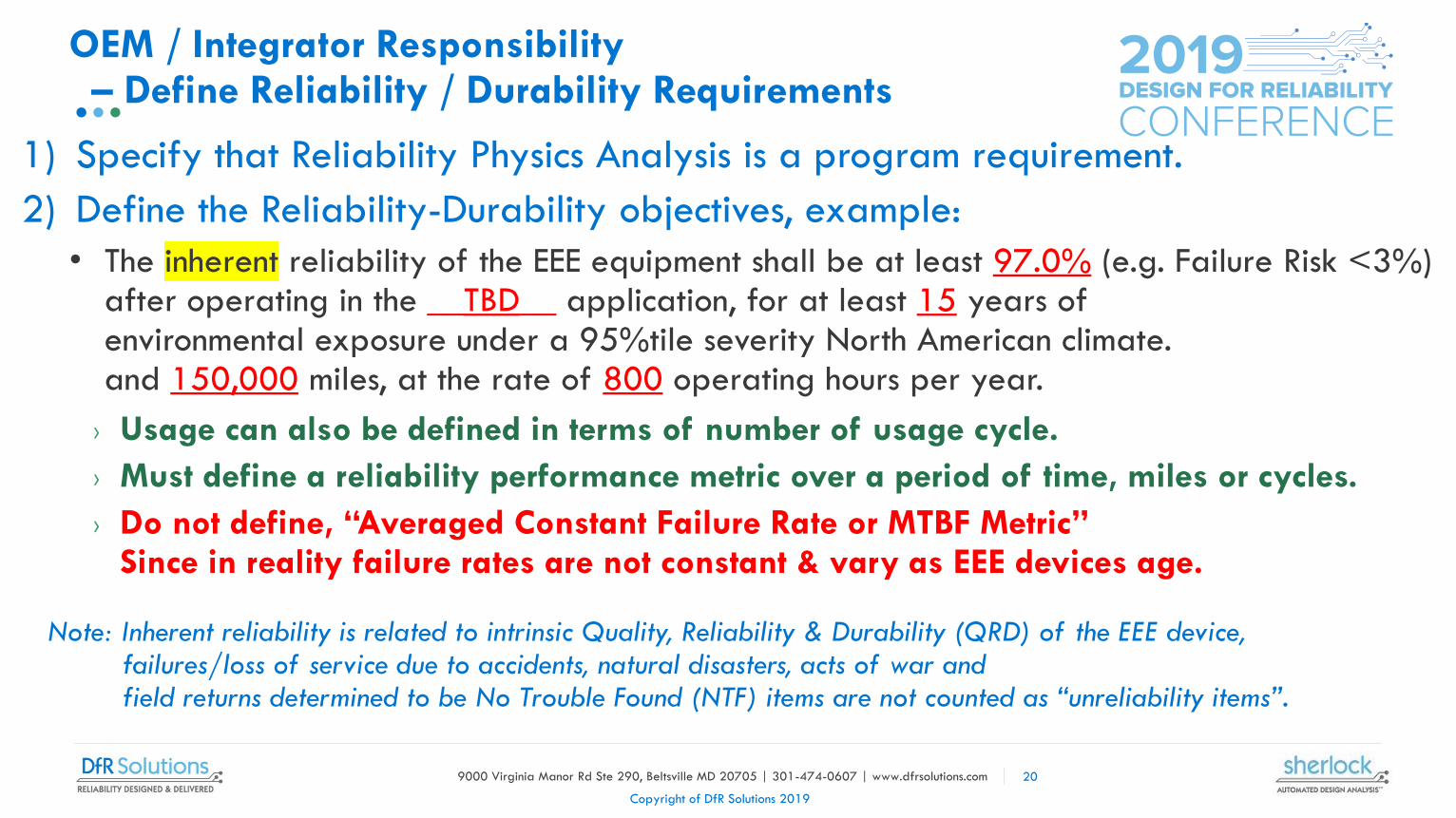
1) Specify that Reliability Physics Analysis is a program requirement.
2) Define the Reliability-Durability objectives, example:
• The inherent reliability of the EEE equipment shall be at least 97.0% (e.g. Failure Risk <3%)after operating in the __TBD__ application, for at least 15 years of environmental exposure under a 95%tile severity North American climate. and 150,000 miles, at the rate of 800 operating hours per year.
Note: Inherent reliability is related to intrinsic Quality, Reliability & Durability (QRD) of the EEE device, failures/loss of service due to accidents, natural disasters, acts of war and field returns determined to be No Trouble Found (NTF) items are not counted as “unreliability items”.
OEM / Integrator Responsibility – Define Reliability / Durability Requirements
› Usage can also be defined in terms of number of usage cycle.
› Must define a reliability performance metric over a period of time, miles or cycles.
› Do not define, “Averaged Constant Failure Rate or MTBF Metric” Since in reality failure rates are not constant & vary as EEE devices age.
20

9000 Virginia Manor Rd Ste 290, Beltsville MD 20705 | 301-474-0607 | www.dfrsolutions.com
Copyright of DfR Solutions 2019
3) Define the dynamic life time field mission and/or test profile of each applicable usage & environmental stress conditions for the application (Ref. SAE J1211-Sect 6: Mission Profile)
OEM / Integrator Responsibility – Define Life Time Load/Stress Profiles
• A simple operating temperature range (i.e. -40C to +85C) is insufficient
• Need to define the number of lifetime thermal cycles the EEE device is expected to endure both while operating and when turned off.
• From climatic/solar environment, adjacent heat sources & power dissipation self-heating.
• Random & sinusoidal vibration freq. range & life time duration time.
• Number, amplitude and pulse duration of shock events.
• Etc.
21

9000 Virginia Manor Rd Ste 290, Beltsville MD 20705 | 301-474-0607 | www.dfrsolutions.com
Copyright of DfR Solutions 2019
MISSION PROFILE DEVELOPMENT PROCESS FLOW
Source: SAE J1211Robustness
Validation of Automotive
Electrical/Electronic Modules Sect 6:
Mission Profile(Figure 10)
22

9000 Virginia Manor Rd Ste 290, Beltsville MD 20705 | 301-474-0607 | www.dfrsolutions.com
Copyright of DfR Solutions 2019
4) The RPA Process Owner is the organization or person(s) that works with the customer to develops & implements a RPA process plan for an EEE Device Development Program.
23
Require Supplier/Contractor to Have RPA Process Owner to Implement & Manage the RPA Process
− Identify the application specific models and simulations to used.
−Determine if addition failure modes/mechanisms need to be evaluated.
−Obtains the design info for the EEE device (i.e. PCB layout, specs, BOM Part lists . . . Etc).
−Obtain and review the life time load/stress mission profiles.
−Select CAE tools and modeling personnel as needed (keep tools & training up to date)
−Review and approve modeling/simulation results.
−Oversee the RPA results report.
− Lead or oversee prioritizing any unacceptable failure risks for potential corrective action.
−Make any needed corrective action or optimization improvement recommendations.
−Present results & reports.

9000 Virginia Manor Rd Ste 290, Beltsville MD 20705 | 301-474-0607 | www.dfrsolutions.com
Copyright of DfR Solutions 2019
Any questions?
24
Thank you for your attention.
Contacts for Additional Information
Jim McLeish – [email protected]
Lloyd Condra – [email protected]