horizontal drilling-knoll
TRANSCRIPT
AAPG Webinar on ComplexAAPG Webinar on ComplexAAPG Webinar on Complex AAPG Webinar on Complex Well GuidanceWell Guidance
R.G. “Bob” Knoll,R.G. “Bob” Knoll,,,
President, HPresident, H--Tech. Petroleum Tech. Petroleum Consulting Inc.Consulting Inc.gg
Calgary, Calgary, Alberta, CanadaAlberta, CanadaThursday, January 28, 2010Thursday, January 28, 2010Thursday, January 28, 2010Thursday, January 28, 2010
Background and PlanBackground and Plan•• Guidance; Taken from Chapter 6 of the Complex Guidance; Taken from Chapter 6 of the Complex
Well Core Competency, (CWCC), 5Well Core Competency, (CWCC), 5--day asset day asset team crossteam cross training program on horizontal welltraining program on horizontal wellteam crossteam cross--training program on horizontal well training program on horizontal well exploitation.exploitation.
To address “guidance” we first must assumeTo address “guidance” we first must assume•• To address “guidance”, we first must assume To address “guidance”, we first must assume you have a core competency understanding of you have a core competency understanding of the basics of directional drilling, horizontal wellthe basics of directional drilling, horizontal wellthe basics of directional drilling, horizontal well the basics of directional drilling, horizontal well profile design, and Geoprofile design, and Geo--steering, a major failure steering, a major failure mode, even in “Resource” plays.mode, even in “Resource” plays.
•• A quick review of the first 2 will be conductedA quick review of the first 2 will be conducted
•• Will deliver as much as possible in 45 minutesWill deliver as much as possible in 45 minutes•• Will deliver as much as possible in 45 minutes, Will deliver as much as possible in 45 minutes, then 15 minute Q&A.then 15 minute Q&A.
11stst-- Well Profile DesignWell Profile DesignO ti i d hO ti i d h ll t b d i d b kll t b d i d b k tt•• Optimized hOptimized h--wells must be designed backwells must be designed back--toto--front with a sitefront with a site--specific multidiscipline team specific multidiscipline team working with a 3D geometric well plan =working with a 3D geometric well plan =working with a 3D geometric well plan = working with a 3D geometric well plan = PROFILE. We then generate an artificial survey PROFILE. We then generate an artificial survey file of the planned profile to prefile of the planned profile to pre--engineer the engineer the p p pp p p ggwell, rig requirements, hydraulic design etc.well, rig requirements, hydraulic design etc.
•• This is a new demand, not considered in vertical This is a new demand, not considered in vertical ,,wells & is a critical element for optimized wells & is a critical element for optimized application with complex wells. application with complex wells.
•• There is no standard design, each must be siteThere is no standard design, each must be site--specifically customized by the team, once specifically customized by the team, once drilled is fixed, & effects all life cycle drilled is fixed, & effects all life cycle capabilities & even the production process.capabilities & even the production process.
33
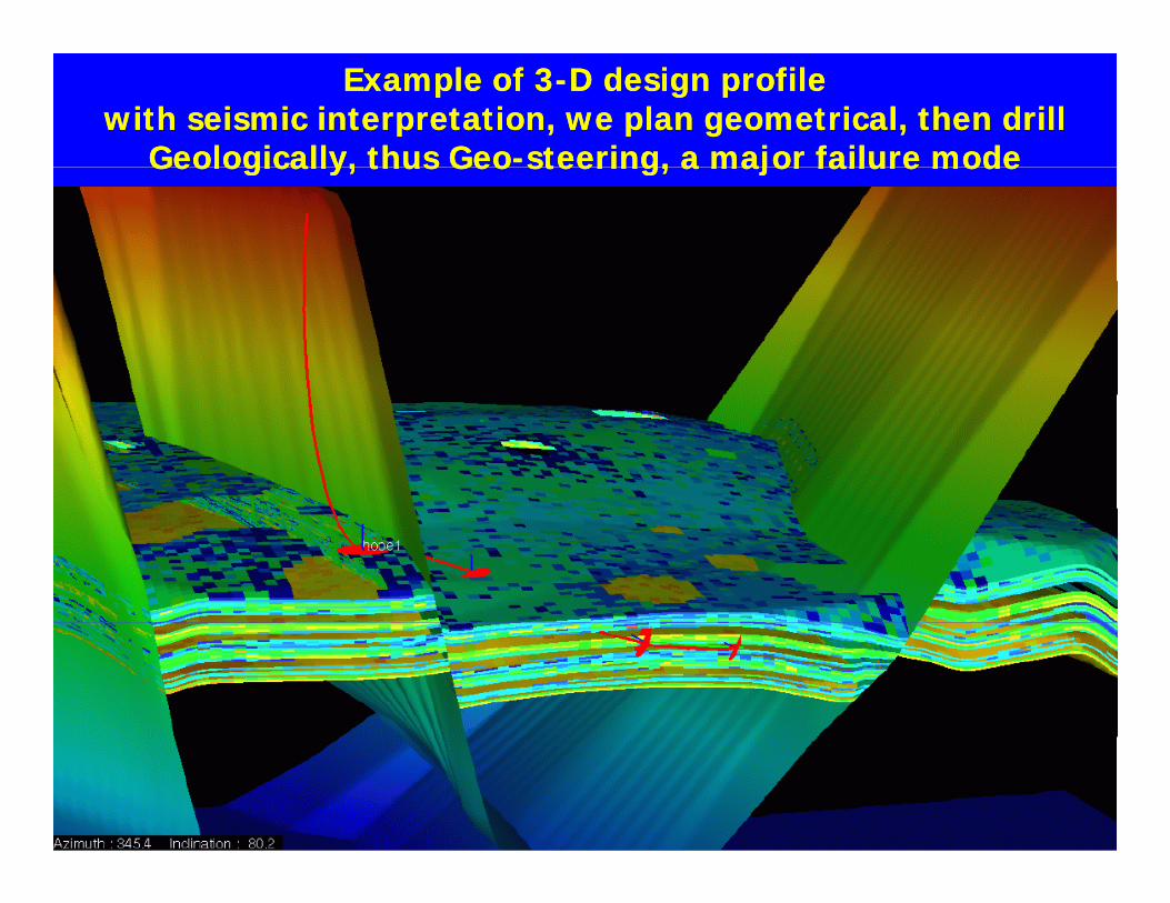
Example of 3Example of 3--D design profile D design profile with seismic interpretation, we plan geometrical, then drill with seismic interpretation, we plan geometrical, then drill
Geologically, thus GeoGeologically, thus Geo--steering, a major failure modesteering, a major failure modeGeologically, thus GeoGeologically, thus Geo steering, a major failure mode steering, a major failure mode
44
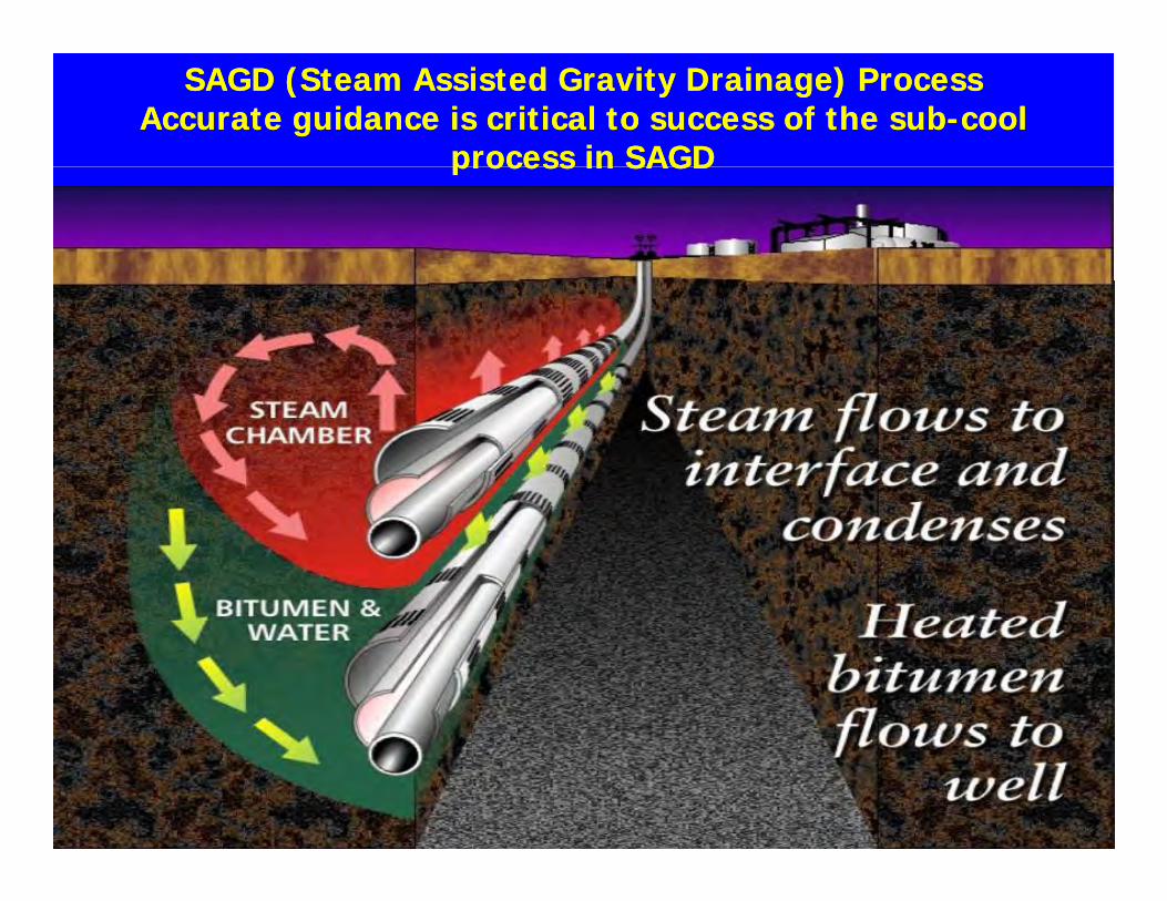
SAGD (Steam Assisted Gravity Drainage) ProcessSAGD (Steam Assisted Gravity Drainage) ProcessAccurate guidance is critical to success of the subAccurate guidance is critical to success of the sub--cool cool
process in SAGDprocess in SAGDprocess in SAGDprocess in SAGD
55
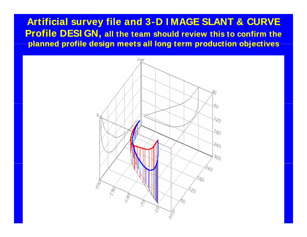
Artificial survey file and 3Artificial survey file and 3--D IMAGE SLANT & CURVE D IMAGE SLANT & CURVE Profile DESIGN, Profile DESIGN, all the team should review this to confirm the all the team should review this to confirm the planned profile design meets all long term production objectivesplanned profile design meets all long term production objectivesplanned profile design meets all long term production objectivesplanned profile design meets all long term production objectives
66
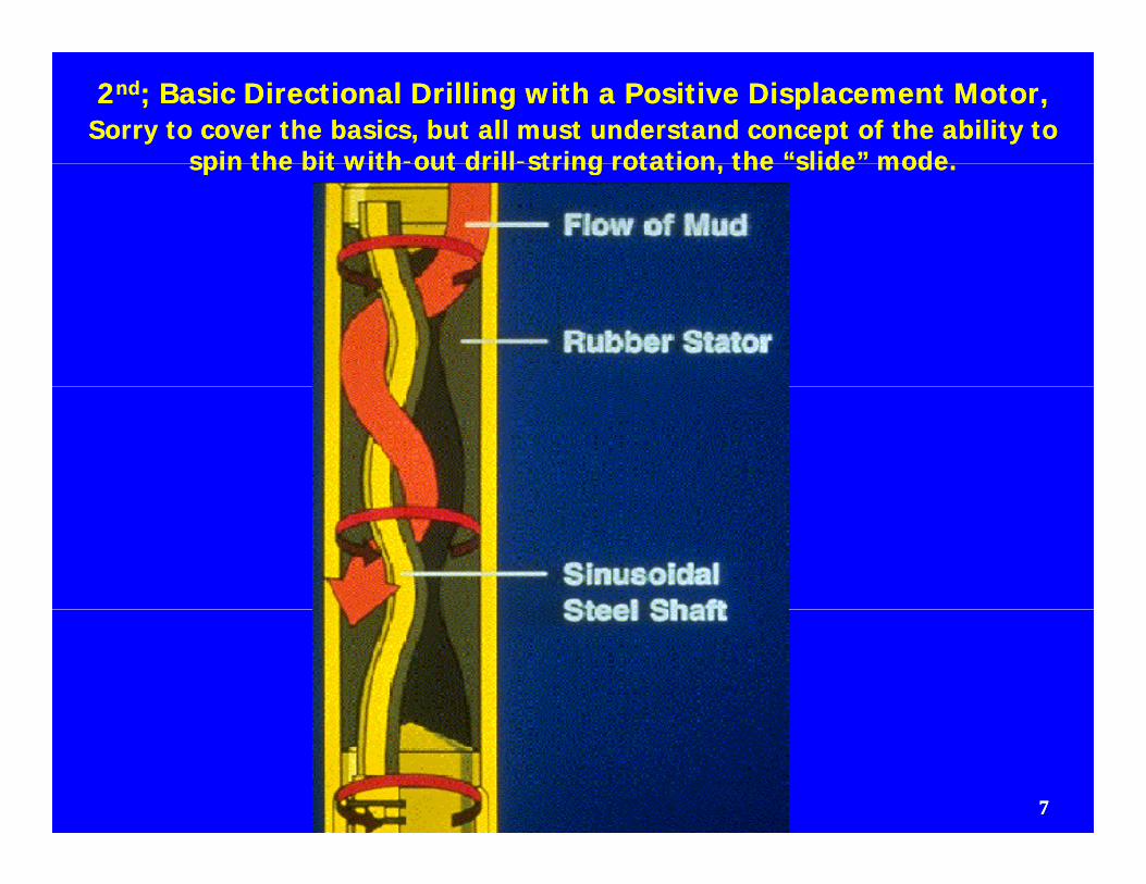
22ndnd; Basic Directional Drilling with a Positive Displacement Motor,; Basic Directional Drilling with a Positive Displacement Motor,Sorry to cover the basics, but all must understand concept of the ability to Sorry to cover the basics, but all must understand concept of the ability to
spin the bit withspin the bit with--out drillout drill--string rotation the “slide” modestring rotation the “slide” modespin the bit withspin the bit with out drillout drill string rotation, the slide mode.string rotation, the slide mode.
77
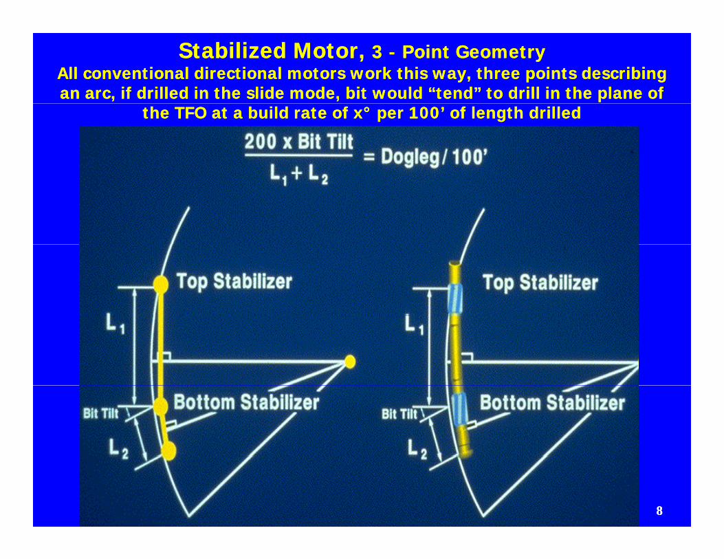
Stabilized Motor, Stabilized Motor, 3 3 -- Point GeometryPoint GeometryAll conventional directional motors work this way, three points describing All conventional directional motors work this way, three points describing an arc, if drilled in the slide mode, bit would “tend” to drill in the plane of an arc, if drilled in the slide mode, bit would “tend” to drill in the plane of
the TFO at a build rate of xthe TFO at a build rate of x°° per 100’ of length drilledper 100’ of length drilled
88
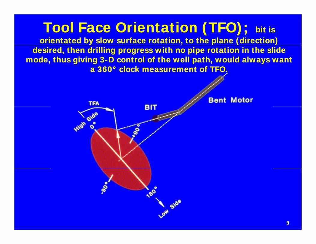
Tool Face Orientation (TFO); Tool Face Orientation (TFO); bit is bit is orientated by slow surface rotation, to the plane (direction) orientated by slow surface rotation, to the plane (direction)
desired, then drilling progress with no pipe rotation in the slide desired, then drilling progress with no pipe rotation in the slide mode, thus giving 3mode, thus giving 3--D control of the well path, would always want D control of the well path, would always want
a 360a 360°° clock measurement of TFO.clock measurement of TFO.
99
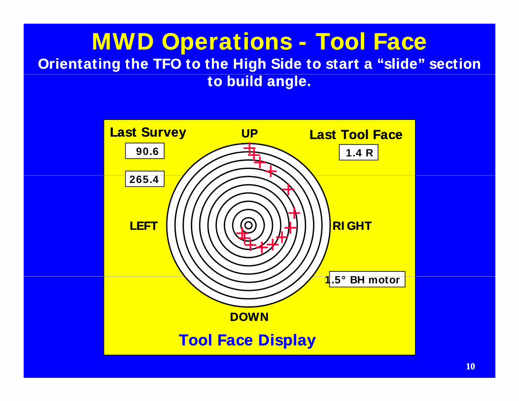
MWD Operations MWD Operations -- Tool FaceTool FaceOrientating the TFO to the High Side to start a “slide” section Orientating the TFO to the High Side to start a “slide” section
to build angle.to build angle.
90.6
265 4
1.4 R
Last SurveyLast Survey Last Tool FaceLast Tool FaceUPUP
265.4
RIGHTRIGHTLEFTLEFT
1 5° BH t
RIGHTRIGHTLEFTLEFT
1.5° BH motor
DOWNDOWN
1010
Tool Face DisplayTool Face Display
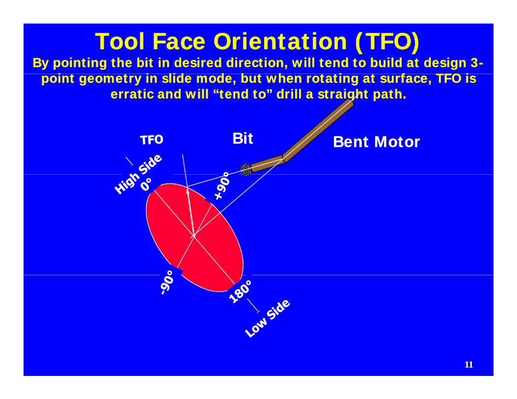
Tool Face Orientation (TFO)Tool Face Orientation (TFO)By pointing the bit in desired direction, will tend to build at design 3By pointing the bit in desired direction, will tend to build at design 3--
i t t i lid d b t h t ti t f TFO ii t t i lid d b t h t ti t f TFO ipoint geometry in slide mode, but when rotating at surface, TFO is point geometry in slide mode, but when rotating at surface, TFO is erratic and will “tend to” drill a straight path.erratic and will “tend to” drill a straight path.
BitBit Bent MotorBent Motor
1111
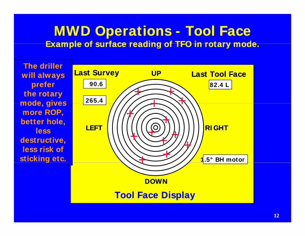
MWD Operations MWD Operations -- Tool FaceTool FaceExample of surface reading of TFO in rotary modeExample of surface reading of TFO in rotary modeExample of surface reading of TFO in rotary mode.Example of surface reading of TFO in rotary mode.
Last SurveyLast Survey Last Tool FaceLast Tool FaceUPUPThe driller The driller
ill lill l90.6
265.4
82.4 L
Last SurveyLast Survey Last Tool FaceLast Tool FaceUPUPwill always will always preferprefer
the rotary the rotary mode givesmode gives
RIGHTRIGHTLEFTLEFT
mode, gives mode, gives more ROP, more ROP, better hole, better hole,
lessless
1.5° BH motor
less less destructive,destructive,less risk of less risk of
sticking etc.sticking etc.
DOWNDOWN
T l F Di lT l F Di l
gg
1212
Tool Face DisplayTool Face Display
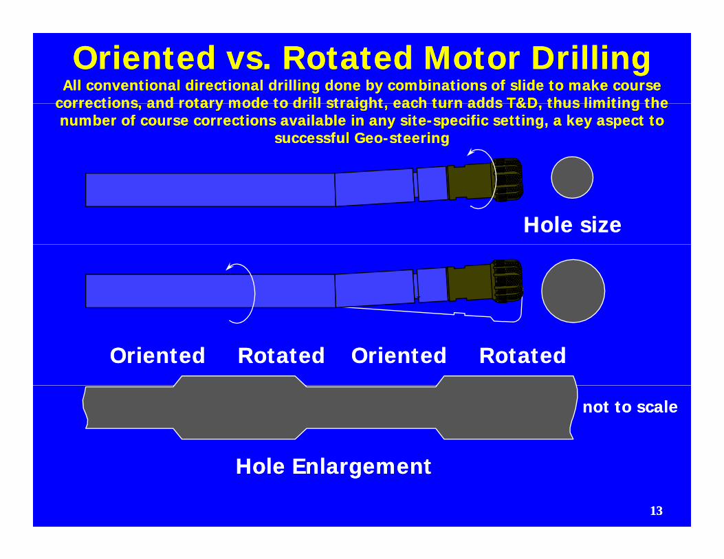
Oriented vs. Rotated Motor DrillingOriented vs. Rotated Motor DrillingAll conventional directional drilling done by combinations of slide to make course All conventional directional drilling done by combinations of slide to make course
corrections and rotary mode to drill straight each turn adds T&D thus limiting thecorrections and rotary mode to drill straight each turn adds T&D thus limiting thecorrections, and rotary mode to drill straight, each turn adds T&D, thus limiting the corrections, and rotary mode to drill straight, each turn adds T&D, thus limiting the number of course corrections available in any sitenumber of course corrections available in any site--specific setting, a key aspect to specific setting, a key aspect to
successful Geosuccessful Geo--steeringsteering
Hole sizeHole size
Oriented RotatedOriented Rotated Oriented RotatedOriented Rotated
not to scalenot to scale
1313
Hole EnlargementHole Enlargement
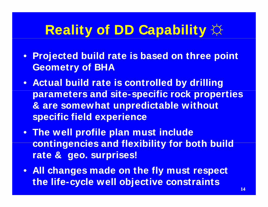
Reality of DD Capability Reality of DD Capability ☼☼
•• Projected build rate is based on three point Projected build rate is based on three point G t f BHAG t f BHAGeometry of BHAGeometry of BHA
•• Actual build rate is controlled by drilling Actual build rate is controlled by drilling d id i ifi k iifi k iparameters and siteparameters and site--specific rock properties specific rock properties
& are somewhat unpredictable without & are somewhat unpredictable without specific field experiencespecific field experiencespecific field experiencespecific field experience
•• The well profile plan must include The well profile plan must include contingencies and flexibility for both buildcontingencies and flexibility for both buildcontingencies and flexibility for both build contingencies and flexibility for both build rate & geo. surprises!rate & geo. surprises!
All changes made on the fly must respectAll changes made on the fly must respect
1414
•• All changes made on the fly must respect All changes made on the fly must respect the lifethe life--cycle well objective constraintscycle well objective constraints
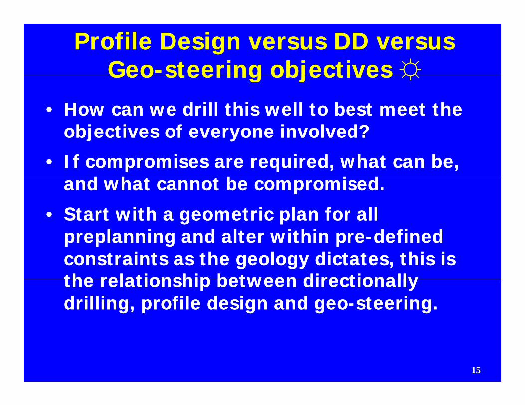
Profile Design versus DD versus Profile Design versus DD versus GeoGeo--steering objectivessteering objectives ☼☼GeoGeo steering objectives steering objectives ☼☼
•• How can we drill this well to best meet the How can we drill this well to best meet the bj ti f i l d?bj ti f i l d?objectives of everyone involved? objectives of everyone involved?
•• If compromises are required, what can be, If compromises are required, what can be, d h b i dd h b i dand what cannot be compromised.and what cannot be compromised.
•• Start with a geometric plan for all Start with a geometric plan for all preplanning and alter within prepreplanning and alter within pre--defined defined constraints as the geology dictates, this is constraints as the geology dictates, this is the relationship between directionallythe relationship between directionallythe relationship between directionally the relationship between directionally drilling, profile design and geodrilling, profile design and geo--steering.steering.
1515
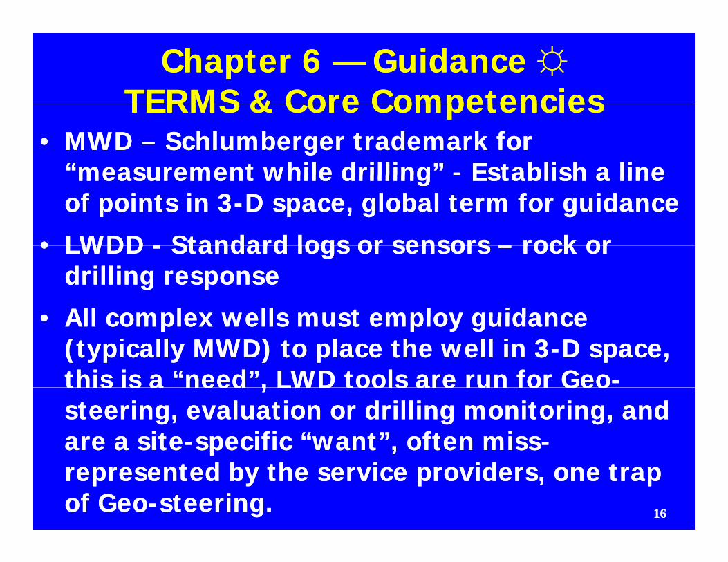
Chapter 6 Chapter 6 —— Guidance Guidance ☼☼TERMS & Core CompetenciesTERMS & Core CompetenciesTERMS & Core CompetenciesTERMS & Core Competencies
•• MWD MWD –– Schlumberger trademark for Schlumberger trademark for “measurement while drilling”“measurement while drilling” -- Establish a lineEstablish a linemeasurement while drilling measurement while drilling Establish a line Establish a line of points in 3of points in 3--D space, global term for guidanceD space, global term for guidance
•• LWDDLWDD -- Standard logs or sensorsStandard logs or sensors –– rock orrock or•• LWDD LWDD -- Standard logs or sensors Standard logs or sensors –– rock or rock or drilling responsedrilling response
•• All complex wells must employ guidanceAll complex wells must employ guidance•• All complex wells must employ guidance All complex wells must employ guidance (typically MWD) to place the well in 3(typically MWD) to place the well in 3--D space, D space, this is a “need”, LWD tools are run for Geothis is a “need”, LWD tools are run for Geo--this is a need , LWD tools are run for Geothis is a need , LWD tools are run for Geosteering, evaluation or drilling monitoring, and steering, evaluation or drilling monitoring, and are a siteare a site--specific “want”, often missspecific “want”, often miss--represented by the service providers, one trap represented by the service providers, one trap of Geoof Geo--steering.steering. 1616
GUIDANCE VS. GEOSTEERING GUIDANCE VS. GEOSTEERING ☼☼•• GUIDANCE refers to the directional drilling GUIDANCE refers to the directional drilling
tools and methods employed to define & tools and methods employed to define & control where the well is in 3D spacecontrol where the well is in 3D spacecontrol where the well is in 3D space.control where the well is in 3D space.
•• The most common method of measurement The most common method of measurement is MWD with mud pulse telemetry otheris MWD with mud pulse telemetry otheris MWD with mud pulse telemetry, other is MWD with mud pulse telemetry, other telemetries include, EM, Inteltelemetries include, EM, Intel--pipe and the pipe and the old steering tools.old steering tools.old steering tools.old steering tools.
•• Other forms of Guidance include “Gyro” Other forms of Guidance include “Gyro” MWD Magnetic Ranging and “seeker”MWD Magnetic Ranging and “seeker”MWD, Magnetic Ranging and seeker MWD, Magnetic Ranging and seeker technologies for relief well and intersector technologies for relief well and intersector applications.applications.pppp
1717
MWD Guidance Definitions MWD Guidance Definitions ☼☼All MWD’s will provideAll MWD’s will provide°° 3, and only 3, measurements3, and only 3, measurements
•• INCLINATION INCLINATION -- vertical angle vertical angle –– measured measured with a Triaxial Accelerometer (measures the with a Triaxial Accelerometer (measures the
ll f it )ll f it )pull of gravity)pull of gravity)
•• AZIMUTH AZIMUTH -- Degrees off the North Degrees off the North –– South South ti li ( t d)ti li ( t d)magnetic lines (compensated) magnetic lines (compensated) –– measure measure
with a with a TriaxialTriaxial MagnetometerMagnetometer
•• TOOL FACE ORIENTATION TOOL FACE ORIENTATION --measure tool orientation measure tool orientation –– highhigh--side or side or
up = 0up = 0°° TFO East = 90TFO East = 90°° lowlow side or downside or downup, = 0up, = 0°° TFO, East = 90TFO, East = 90°°, low, low--side or down side or down = 180= 180°°, ,
1818
MWD MWD ☼☼
•• Fast? and efficient way to get surveysFast? and efficient way to get surveysIn conjunction with motors and fixed cutters bit, In conjunction with motors and fixed cutters bit,
can be more economic and drift tools are now can be more economic and drift tools are now used in vused in v--well applicationswell applicationsusedused e app cat o se app cat o s
•• Subject to magnetic interference and Subject to magnetic interference and vibration damagevibration damagevibration damagevibration damage
•• Electromagnetic MWD can be used in Electromagnetic MWD can be used in compressible fluid drilling, has less movingcompressible fluid drilling, has less movingcompressible fluid drilling, has less moving compressible fluid drilling, has less moving parts, higher baud rate and cleaner data, parts, higher baud rate and cleaner data, may replace mudmay replace mud--pulse in time as depth pulse in time as depth limit is overcomelimit is overcome
1919
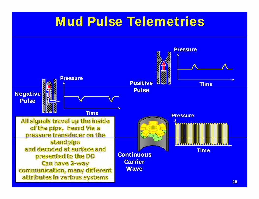
Mud Pulse TelemetriesMud Pulse Telemetries
PressurePressure
PressurePressureTimeTimePositivePositive
TimeTime
NegativeNegativePulsePulse
PulsePulse
TimeTime PressurePressure
TimeTimeContinuousContinuous
CarrierCarrier
2020
CarrierCarrierWaveWave
Data TransmissionData Transmission
•• All logging tools are generally the sameAll logging tools are generally the same
•• Transmit data by hard wire, magnetic waves Transmit data by hard wire, magnetic waves or mud pulsesor mud pulses
•• All are binary signals ( 0 or 1 )All are binary signals ( 0 or 1 )
•• Mud pulsesMud pulsesMud pulses Mud pulses -- will not work in aerated fluids will not work in aerated fluids -- need pump pulsation dampeners need pump pulsation dampeners -- “Y” pump discharge connections“Y” pump discharge connections
•• Power supplied by batteries or a turbine, Power supplied by batteries or a turbine, many variation of attributes and capabilitiesmany variation of attributes and capabilities
2121
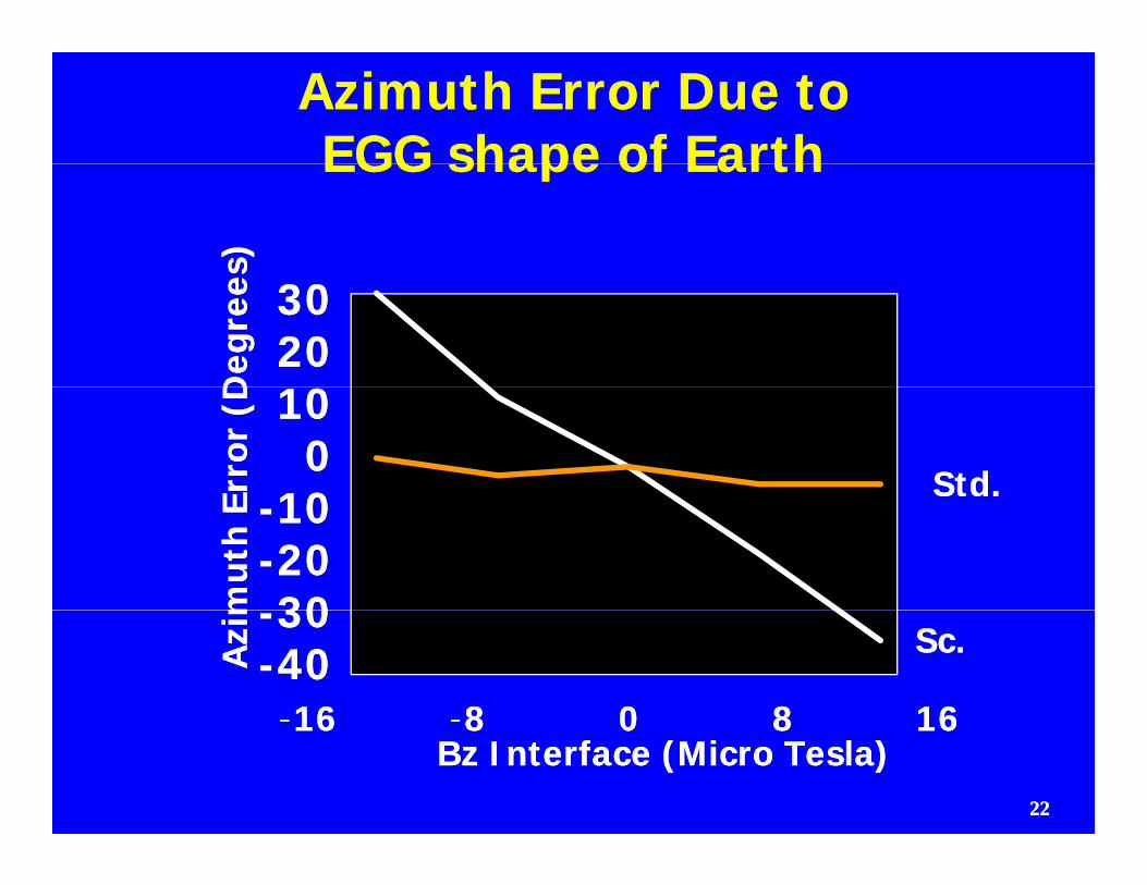
Azimuth Error Due to Azimuth Error Due to EGG shape of EarthEGG shape of EarthEGG shape of Earth EGG shape of Earth
s)s)D
egre
eD
egre
e 30302020
00
Erro
r (D
Erro
r (D
Std.Std.
101000
1010
mut
h E
mut
h E --1010
--20203030
Azi
mA
zim
Sc.Sc.--3030--4040--1616 --8 0 8 168 0 8 16
2222
Bz Interface (Micro Tesla)Bz Interface (Micro Tesla)16 16 8 0 8 168 0 8 16
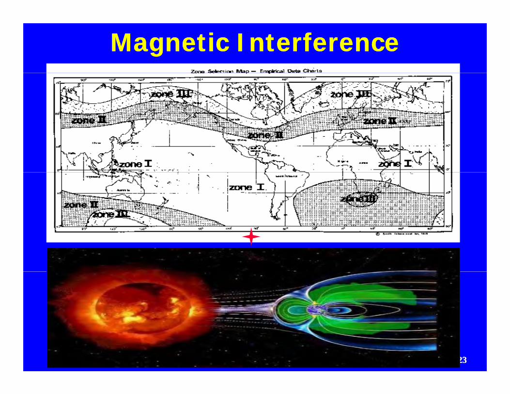
Magnetic Interference Magnetic Interference
2323
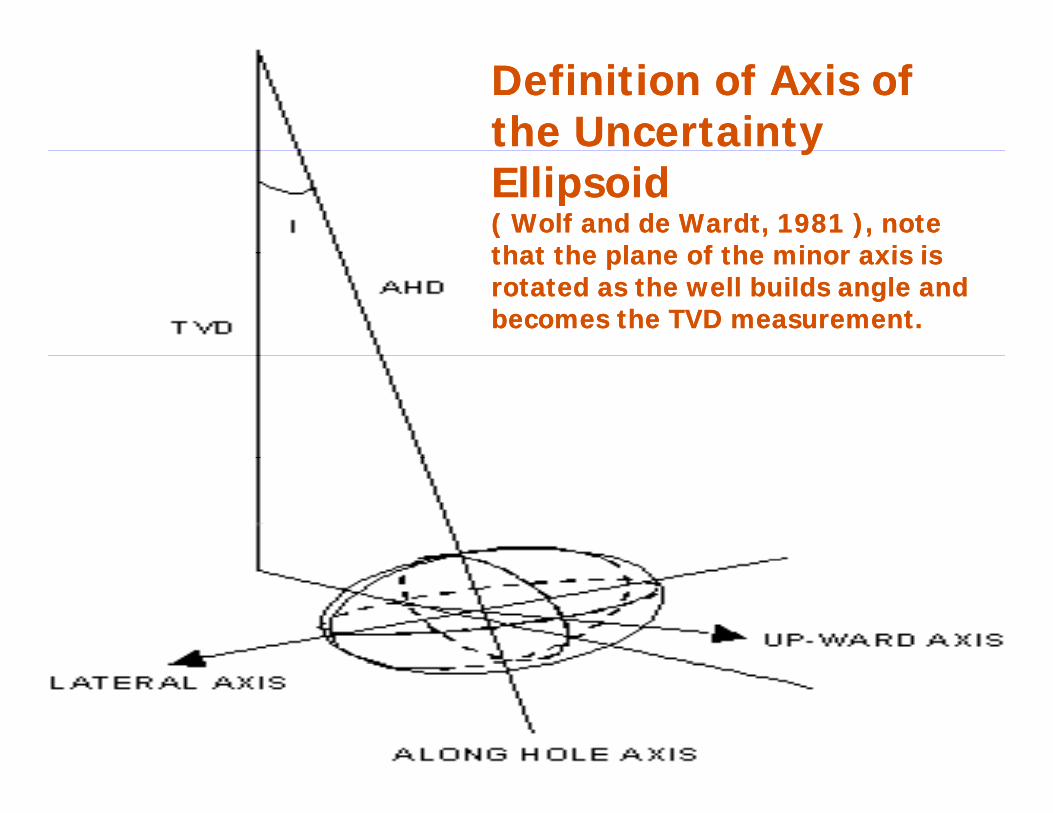
Definition of Axis of Definition of Axis of the Uncertainty the Uncertainty yyEllipsoidEllipsoid( Wolf and de Wardt, 1981 ), note ( Wolf and de Wardt, 1981 ), note that the plane of the minor axis isthat the plane of the minor axis isthat the plane of the minor axis is that the plane of the minor axis is rotated as the well builds angle and rotated as the well builds angle and becomes the TVD measurement.becomes the TVD measurement.
2424
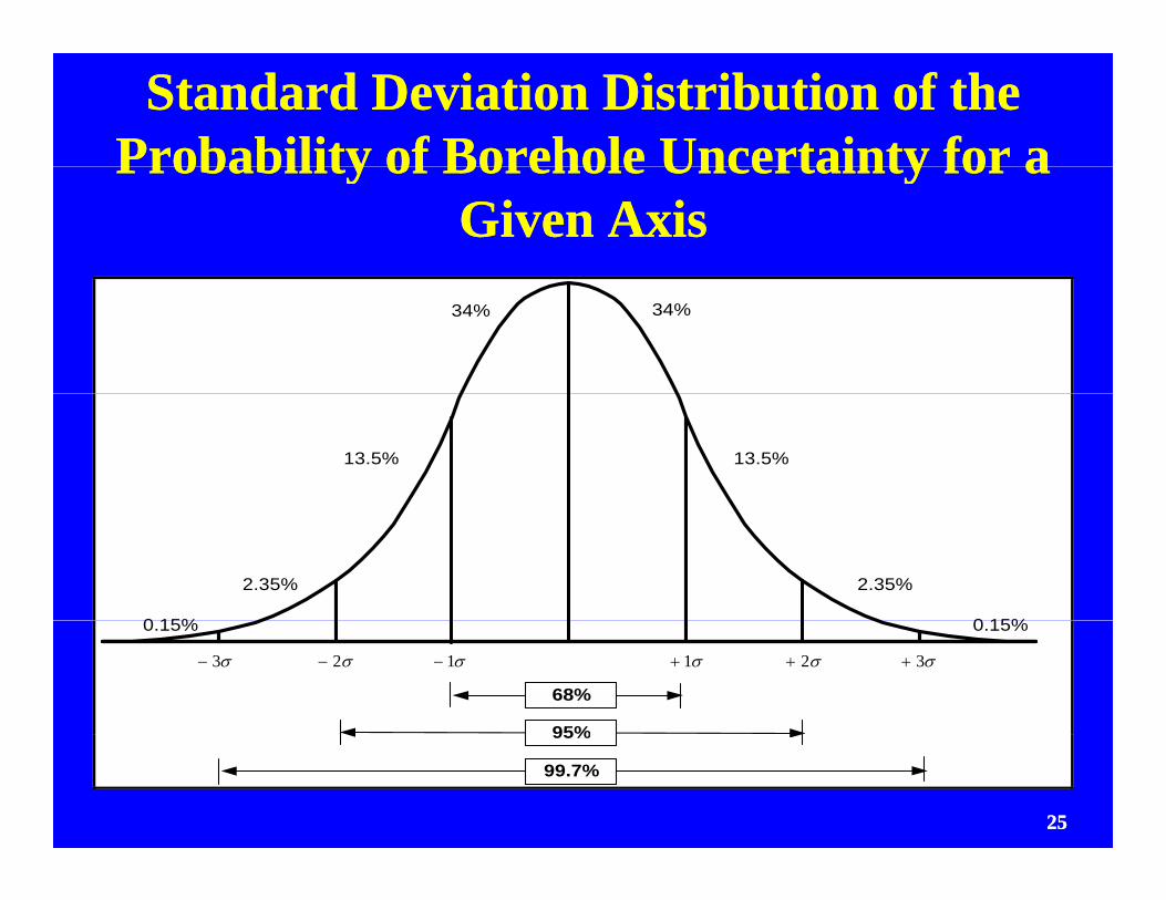
Standard Deviation Distribution of the Standard Deviation Distribution of the Probability of Borehole Uncertainty for aProbability of Borehole Uncertainty for aProbability of Borehole Uncertainty for a Probability of Borehole Uncertainty for a
Given AxisGiven Axis34% 34%
13.5% 13.5%
2.35%
0 15%
2.35%
0 15%
3 2 1 1 2 3
95%
68%
0.15% 0.15%
2525
99.7%
95%
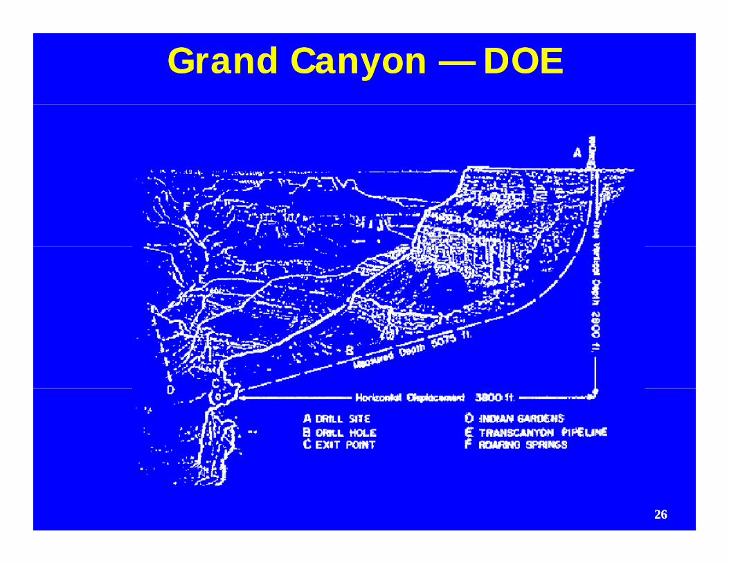
Grand Canyon Grand Canyon —— DOE DOE
2626
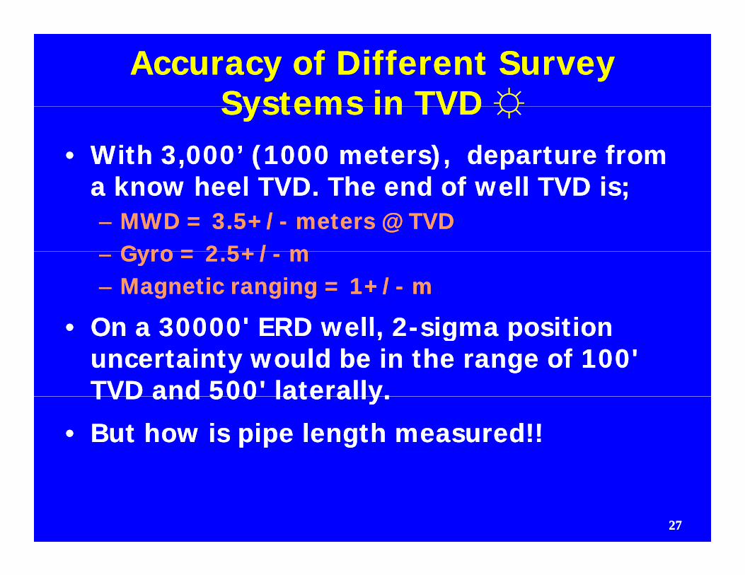
Accuracy of Different Survey Accuracy of Different Survey Systems in TVDSystems in TVD ☼☼Systems in TVD Systems in TVD ☼☼
•• With 3,000’ (1000 meters), departure from With 3,000’ (1000 meters), departure from k h l TVD Th d f ll TVD ik h l TVD Th d f ll TVD ia know heel TVD. The end of well TVD is;a know heel TVD. The end of well TVD is;
–– MWD = 3.5+/MWD = 3.5+/-- meters @ TVDmeters @ TVDGyro = 2 5+/Gyro = 2 5+/ mm–– Gyro = 2.5+/Gyro = 2.5+/-- mm
–– Magnetic ranging = 1+/Magnetic ranging = 1+/-- mm
•• On a 30000' ERD well 2On a 30000' ERD well 2 sigma positionsigma position•• On a 30000 ERD well, 2On a 30000 ERD well, 2--sigma position sigma position uncertainty would be in the range of 100' uncertainty would be in the range of 100' TVD and 500' laterally.TVD and 500' laterally.TVD and 500 laterally. TVD and 500 laterally.
•• But how is pipe length measured!!But how is pipe length measured!!
2727
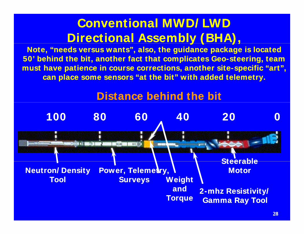
Conventional MWD/LWDConventional MWD/LWDDirectional Assembly (BHA),Directional Assembly (BHA),y ( ),y ( ),
Note, “needs versus wants”, also, the guidance package is located Note, “needs versus wants”, also, the guidance package is located 50’ behind the bit, another fact that complicates Geo50’ behind the bit, another fact that complicates Geo--steering, team steering, team must have patience in course corrections, another sitemust have patience in course corrections, another site--specific “art”, specific “art”,
can place some sensors “at the bit” with added telemetry.can place some sensors “at the bit” with added telemetry.
Distance behind the bitDistance behind the bit
100100 8080 6060 4040 2020 00
SteerableSteerable
WeightWeightandand
Neutron/DensityNeutron/DensityToolTool
Power, Telemetry,Power, Telemetry,SurveysSurveys
22--mhz Resistivity/mhz Resistivity/
SteerableSteerableMotorMotor
2828
andandTorqueTorque
22--mhz Resistivity/mhz Resistivity/Gamma Ray ToolGamma Ray Tool
ERD & GUIDANCE (1)ERD & GUIDANCE (1)•• Circa January 2009, Baker Hughes websiteCirca January 2009, Baker Hughes website
•• An example of INTEQ’s worldAn example of INTEQ’s world--class work is class work is p Qp Qan ERD project on Sakhalin Island in remote an ERD project on Sakhalin Island in remote Eastern RussiaEastern Russia–– Over a dozen wells in this project have exceeded Over a dozen wells in this project have exceeded
32,808 ft (10,000 m) MD with the longest drilled 32,808 ft (10,000 m) MD with the longest drilled to a measured depth of 38,320 ft (11,680 m).to a measured depth of 38,320 ft (11,680 m).to a measured depth of 38,320 ft (11,680 m). to a measured depth of 38,320 ft (11,680 m).
–– Notable successes include precise positioning of Notable successes include precise positioning of the horizontal drain within a 50the horizontal drain within a 50±± cm nominal cm nominal TVDTVD i di d (@#$^$#@)(@#$^$#@)TVD target TVD target window window (@#$^$#@).(@#$^$#@).
–– A very A very misleading misleading statement!, “the survey is not statement!, “the survey is not written in stone”written in stone”written in stonewritten in stone
–– What Length Measurement, people What Length Measurement, people lose lose pipe pipe joints!!!joints!!! 2929
ERD & GUIDANCE (2)ERD & GUIDANCE (2)•• “Correcting Errors inherent in MWD “Correcting Errors inherent in MWD
Surveying”, Chris Henderson, Weatherford,Surveying”, Chris Henderson, Weatherford,Surveying , Chris Henderson, Weatherford, Surveying , Chris Henderson, Weatherford, Beijing, World Oil January, '09Beijing, World Oil January, '09
•• Current running practices can introduceCurrent running practices can introduceCurrent running practices can introduce Current running practices can introduce gross errors.gross errors.
•• Hole Curvature between surveys. On 93'Hole Curvature between surveys. On 93'•• Hole Curvature between surveys. On 93 Hole Curvature between surveys. On 93 survey intervals, using minimum curvature survey intervals, using minimum curvature method, could be an error of 7.5' per K of method, could be an error of 7.5' per K of , p, phole lengthhole length
•• Can be approximated with “virtual survey” Can be approximated with “virtual survey” pp ypp yor “On the fly” surveysor “On the fly” surveys
3030
ERD & GUIDANCE (3)ERD & GUIDANCE (3)•• Bent Sub Effect, can alter inclination by 1º , Bent Sub Effect, can alter inclination by 1º ,
mitigate with “cluster shot”mitigate with “cluster shot”mitigate with cluster shotmitigate with cluster shot
•• Pipe Stretch, length change of around 2’ per Pipe Stretch, length change of around 2’ per k length.k length.k length.k length.
•• Axial misalignment of pipe in hole, could Axial misalignment of pipe in hole, could relate to 1' error per K lengthrelate to 1' error per K lengthrelate to 1 error per K lengthrelate to 1 error per K length
•• “I am not aware of any provider or product “I am not aware of any provider or product that handles these errors at present”that handles these errors at present”that handles these errors at presentthat handles these errors at present
•• How do we measure the length of pipe in How do we measure the length of pipe in the hole?the hole?the hole?the hole?
3131
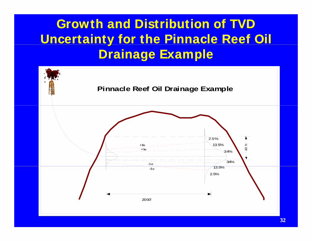
Growth and Distribution of TVD Growth and Distribution of TVD Uncertainty for the Pinnacle Reef Oil Uncertainty for the Pinnacle Reef Oil yy
Drainage ExampleDrainage Example
Pinnacle Reef Oil Drainage Example
40 ft
+1+2
- 1
2.5%
13.5%
34%
34%
13 5%- 2 13.5%
2.5%
3232
2000'
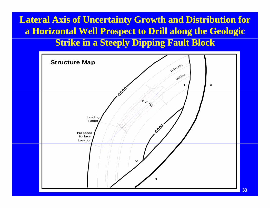
Lateral Axis of Uncertainty Growth and Distribution for Lateral Axis of Uncertainty Growth and Distribution for a Horizontal Well Prospect to Drill along the Geologic a Horizontal Well Prospect to Drill along the Geologic
Strike in a Steeply Dipping Fault BlockStrike in a Steeply Dipping Fault Block
Structure Mape r
500
pO il/W
a te r
Oil/Gas
DU
-550
Landing
2 1 12
-5000
ProposedSurfaceLocation
LandingTarget
U
3333
D
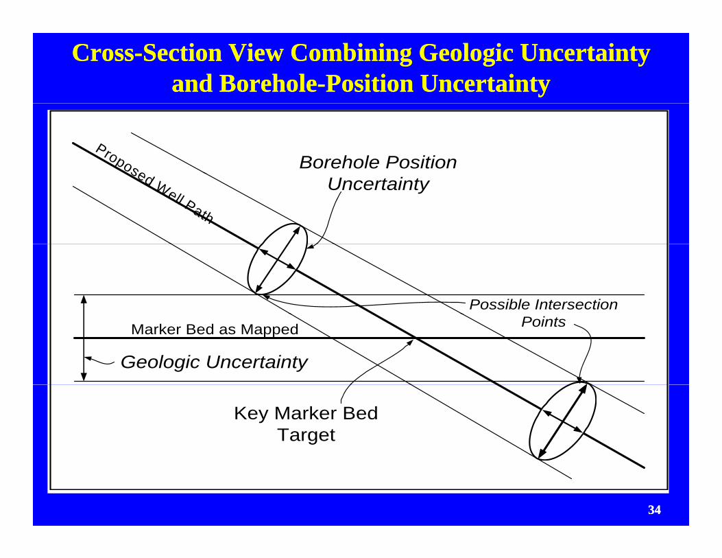
CrossCross--Section View Combining Geologic Uncertainty Section View Combining Geologic Uncertainty and Boreholeand Borehole--Position UncertaintyPosition Uncertainty
Borehole PositionPropose
Uncertaintysed Well Path
Possible Intersection
Marker Bed as Mapped
Geologic Uncertainty
Points
Key Marker BedTarget
3434
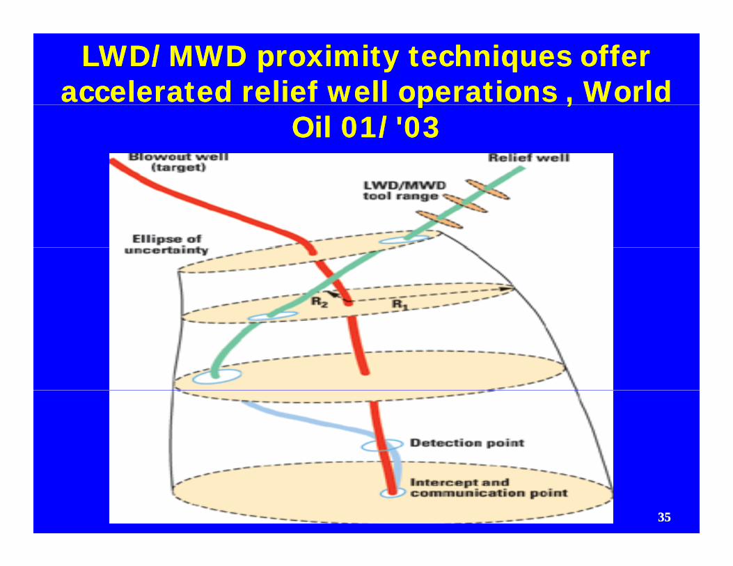
LWD/MWD proximity techniques offer LWD/MWD proximity techniques offer accelerated relief well operations , World accelerated relief well operations , World p ,p ,
Oil 01/'03Oil 01/'03
3535
Update on Intersector Technology (1)Update on Intersector Technology (1)
•• “Connector/Conductor Wells; Multiple “Connector/Conductor Wells; Multiple W llb ith DW llb ith D h l C ti ”h l C ti ”Wellbores with DownWellbores with Down--hole Connections”, hole Connections”, Brunei Shell, SPE # 111411, JPT May 2008.Brunei Shell, SPE # 111411, JPT May 2008.
N b 2006 Sh ll d ill d HN b 2006 Sh ll d ill d H dd•• November 2006, Shell drilled HNovember 2006, Shell drilled H--producer producer from onshore to intersect with deviated from onshore to intersect with deviated “conductor” well offshore Conductor well“conductor” well offshore Conductor wellconductor well offshore. Conductor well conductor well offshore. Conductor well to be top abandoned and producing through to be top abandoned and producing through 2 completed zones above intersect point.2 completed zones above intersect point.co p eted o es abo e te sect po tco p eted o es abo e te sect po t
3636
Update on Intersector Technology (2)Update on Intersector Technology (2)
•• Good discussion on “HomingGood discussion on “Homing--in, or seeker” in, or seeker” technology, after twin gyro runs on technology, after twin gyro runs on gy, gygy, gyintermediate casing depthintermediate casing depth–– SideSide--entry singleentry single--wire guidance was first used wire guidance was first used
f 180 M ti f d t t llf 180 M ti f d t t llfrom 180 M separation, found target well was from 180 M separation, found target well was 9m north and 30 M east of survey, corrected 9m north and 30 M east of survey, corrected intersector well path and continued to 45 m intersector well path and continued to 45 m ppseparation, then used “rotatingseparation, then used “rotating--magnet” ranging magnet” ranging system suspended in target well, found target system suspended in target well, found target now 1m north and 15 m east of survey madenow 1m north and 15 m east of survey madenow 1m north and 15 m east of survey, made now 1m north and 15 m east of survey, made sharp course correction then another near sidesharp course correction then another near side--track to avoid collision, all indicators show that track to avoid collision, all indicators show that th 8 5” h l t h d th t t 7” ith 8 5” h l t h d th t t 7” i
3737
the 8.5” hole touched the target 7” casing.the 8.5” hole touched the target 7” casing.
Guidance Uncertainty is RealGuidance Uncertainty is Real•• The team must have The team must have
core competency with core competency with DD, Profile, Guidance DD, Profile, Guidance and Geoand Geo--steering if steering if well is to be a successwell is to be a successwell is to be a successwell is to be a success
•• Be aware of Be aware of measurement errors, measurement errors, particularly with pipeparticularly with pipeparticularly with pipe particularly with pipe lengthlength
•• Must roll test and Must roll test and calibrate tools on sitecalibrate tools on sitecalibrate tools on sitecalibrate tools on site
•• Must have competent Must have competent service providersservice providers
•• If not, it is very If not, it is very possible you could be possible you could be going in the wrong going in the wrong direction, a commondirection, a common
3838
direction, a common direction, a common failure mode.failure mode.
AAPG and Other CWCC Staging's, 2010AAPG and Other CWCC Staging's, 2010
ApApril 05ril 05--09 Denver, Colorado hosted by Colorado School 09 Denver, Colorado hosted by Colorado School of Mines/PTTCof Mines/PTTChttp://www.eventbrite.com/event/486497126http://www.eventbrite.com/event/486497126
June 14June 14--18 Regina, Sask. hosted by H18 Regina, Sask. hosted by H--Tech. Petroleum Consulting Tech. Petroleum Consulting http://htech.ca/2010CWCChttp://htech.ca/2010CWCC--Regina.docRegina.doc
July 26July 26--30 Dallas, Texas hosted by AAPG30 Dallas, Texas hosted by AAPGhttp://www.aapg.org/education/shortcourse/details.cfm?ID=181http://www.aapg.org/education/shortcourse/details.cfm?ID=181
September 20September 20--14,Calgary, Alberta hosted by H14,Calgary, Alberta hosted by H--Tech. Tech. http://htech.ca/2010CWCChttp://htech.ca/2010CWCC--Calgary.docCalgary.dochttp://htech.ca/2010CWCChttp://htech.ca/2010CWCC Calgary.docCalgary.doc
November 8November 8--12, Midland, Texas hosted by Midland College12, Midland, Texas hosted by Midland Collegehttp://www.midland.edu/~ppdc/pgtchttp://www.midland.edu/~ppdc/pgtc--spring2010spring2010--listing.html#/complexlisting.html#/complex
3939
Thank YouThank You
R.G. “Bob” Knoll,R.G. “Bob” Knoll,,,
President, HPresident, H--Tech. Petroleum Tech. Petroleum Consulting Inc.Consulting Inc.gg
Calgary, Calgary, Alberta, CanadaAlberta, CanadaThursday, January 28, 2010Thursday, January 28, 2010Thursday, January 28, 2010Thursday, January 28, 2010