holographic interferometry with an laser and two · 2013-08-30 · dual-reference-beam, holographic...
TRANSCRIPT

NASA Technical Memorandum 102056
Holographic Interferometry With an Injection Seeded Nd:YAG Laser and Two Reference Beams
Arthur J. Decker Lewis Research Center Cleveland, Ohio
(N AS A-TU- 10 20 56) ROLOGRA PB IC INTERPE B C8ETBP N89 - 2 45 91
UITE AN IIIJECTION SEEDBD N d : Y B G LASER A N D TU0 REFERENCE BEAMS [NASA. L e v i s Research C e n t e r ) 23 p CSCL 20P Unclas
6 3 / 3 5 0211713
May 1989
https://ntrs.nasa.gov/search.jsp?R=19890015220 2020-04-25T07:09:17+00:00Z

HOLOGRAPHIC INTERFEROMETRY WITH AN INJECTION
SEEDED Nd:YAG LASER AND TWO REFERENCE BEAMS
Arthur J. Decker
National Aeronautics and Space Administration
Lewis Research Center
Cleveland, Ohio 44135
ABSTRACT
The performance of twin injection seeded Nd:YAG lasers is compared
with the performance of an argon-ion laser for recording
dual-reference-beam holograms in AGFA 8356 emulsion. Optical
heterodyning is used to measure interference, and the results are expressed
in terms of heterodyning signal level and inteiisity signal-to-noise. The
Nd:YAG laser system is to be used for optical inspections of structures for
cracks, defects, gas leaks, and structural changes.
I. INTRODUCTION
The injection seeded Nd:YAG technology increases the efficiency of
routine optical inspections using dual-reference-beam holographic
interferometry. This paper will compare the performances of argon-ion
and Nd:YAG lasers for recording dual-referencebeam holograms in Agfa
8E56 emulsion.
The literature contains many discussions of phase-sensi tive electronic
interferometry and electronic moire. Dkdliker and colleagues have done
pioneering work with the holographic implernentati~n.’-~ Rub y-laser ,
dual-reference-beam, holographic interferometry has been discussed by 4 5 Swain and Tansey, and Wagner has described a version using Nd:YAG.
Lewis Research Center has ongoing projects to use the phase sensitive
methods for measurements of flow properties6” and more recently for
structural inspections.
An injectionseeded Nd:YAG laser and dual-reference-beam
holographic interferometry have been used at Lewis Research Center for
crack detection in a composite subjected to high cycle fatigue. Figure 1
compares crack-detection inspections of a sample of composite material
performed with argon-ion and injectionseeded Nd:YAG lasers. Both
plots show numerically evaluated second derivatives of the raw
interference phase measured from fringe patterns recorded by
dual-referencebeam, doublwxposure, holographic interferometry.
2
Optical heterodyning was used to perform the measurements. A point
load was applied to the sample between exposures of the argon-ion laser
hologram. The Nd:YAG hologram was a double exposure of the sample,
recorded while the sample was vibrating in its first cantilever mode. The
second derivatives are seen to deviate significantly from linear in the
neighborhood of the crack. The argon-ion and Nd:YAG holograms were
equally effective for crack detection.
Nd:YAG lasers offer several advantages over argon-ion and ruby lasers
for performing routine optical inspections such as the crack detection
example. The lasers radiate from 5 to 50 Q-switched pulses per second,
making it easy to align the beams relative to an object. The second
harmonic of the Nd:YAG laser at 532 nm is close to the wavelength of
argon-ion at 514.5 nm, so that two argon-ion beams can be used to
reconstruct the fringe patterns for measurement with minimum
wavelength-shift error. The high repetition rates of the lasers make it
possible to perform many optical inspections of short-lived structures.
Dual-reference-beam, holographic interferometry can be performed with
holographic emulsions on film when it is necessary to record more than 7
one hologram per second.
These benefits should be weighed with caution. There are relatively few
examples of Q-switched, Nd:YAG holography, 5,8-10 although Nd:YAG
itself has a good commercial track record. Beam smoothing methods such
as spatial filtering are fairly - difficult to perform with Nd:YAG as with
3
ruby lasers.
A startling property of Nd:YAG laser holography is the change in
performance of the common silver halide emulsions used for holography.
Pulsed laser holograms, with ruby in mind, are quoted as having a factor
of 2 to 4 reciprocity failure.'' i t is shown in this paper that the short
pulses from the Nd:YAG laser (5 nsec to 15 nsec) result in a factor of 4 to
6 reciprocity failure. Everything else equal, this means that a Nd:k'AG
laser will require 4 to 6 times the energy of an argon-ion exposure for a
given hologram situation. This disturbing property is ameliorated
significantly by two facts. First, heterodyne holographic interferometry is
adequate for optical inspections even though the detected signals vary by
2 to 3 orders of magnitude. The factors that determine sensitivity are not
affected very much by the holographic technique, consequently big
mistakes are forgiven. The second fact, substantiated by the
measurements reported herein, is that increasing the temperature of the
developer by 6 to 10 F improves the performance of the silver-halide
emulsions substantially, when they are exposed to the second harmonic of
a Q-switched, Nd:YAG laser.
In this paper, argon-ion at 514.5 nm is compared with Nd:YAG at 532
Hardware, experimental setup, and
The trends established appear to be similar for
nm for the Agfa 8E56 emulsion.
results are discussed.
other holographic emulsions such as Agfa 10E56 and Kodak SO 253.
4
11. INSTRUMENTATION
The principal hardware for this work was a pair of Quantel International
YG580 Series oscillator, amplifier, frequency-doubler combinations and a
single injection seeder. The three lasers were assembled by the
manufacturer and mounted on a single, covered, vibration-isolation table.
The injection seeder causes the Q-switched oscillators to tend to operate
in a single longitudinal mode.12 In the absence of the injection seeder,
Q-switched pulses build up from spontaneous emission propagating within
the oscillator spatial mode. The large line-width of the spontaneous
emission and the moderately high gain of Nd:YAG assure that many
longitudinal modes lase. Consequently, the coherence length of the laser is
very short (less than 1 cm), making it difficult to record holograms of
objects which have any surface relief. During injection seeding, the output
of the injection seeder is mode matched using telescopes to the spatial
modes of the Q-switched oscillators. The injection-seeder light is
directed into the oscillators by reflecting it off the Q-switch polarizers.
The three lasers are tuned to the same frequency using temperature tuning
and by using piezoelectric control of the positions of the high reflectors of
the oscillators. When this package is operating correctly, the Q-switched
pulses build up much earlier than would happen if the spontaneous
emission were in control, and the laser will operate in a single longitudinal
mode. The injectionseeder package is able to monitor this build-up time
5
and to minimize the build-up time by adjusting the piezoelectric
controlled positions of the high reflectors.
The two lasers each produce about 500 mJ per pulse of 532 nm light at
10 pulses per second. The full width at half maximum power of a pulse is
about 7 nanoseconds. The time separation between the two laser pulses
can be adjusted from about 1 to 1000 microseconds for double exposure
holograms. The spectroscopic line-width of a laser pulse is about .005
cm as confirmed by a Michelson interferometer and holography. The
l / e diameter of a green laser beam is about 8 mm. Roughly speaking,
these properties translate into an ability to record good
dual-referencebeam holograms (one laser for each reference beam) of a
diffusely reflecting object with a surface relief of about 0.5 m and a
maximum projected dimension of about 1.0 m.
-1
2
There are some cautions in buying and using such a system in addition
to proper use of the holographic emulsions. One tacit assumption is that
the two lasers produce beams which are identical geometrically, have the
same frequency, and are precisely coaxial at the object. Otherwise
systematic phase errors and relative specklepattern shifts can occur.
Differences in the beam properties have not so far affected the optical
inspection applications. Bean differences and misalignment could become
important if more exact numerical results are required. A more noticeable
effect has been less reliability in getting an injection-seeded second pulse
as the pulse separation decreases, especially below 100 microseconds.
6
A second principal item is a Coherent Innova 90 argon-ion laser used for
reconstruction and for fringe measurements. This laser was also used to
record the argon-ion holograms which were compared with the Nd:YAG
holograms. For reconstructions and measurements, the laser was always
operated at a wavelength of 514.5 nm, at a power of 325 mW, and with its
etalon installed. The l/e" diameter of this laser beam is about 1.5 mm. 3
The argon-ion laser and the fringe measurment station are supported by
a large vibration-isolation table. Fringe measurements are accomplished
with a setup similar to that described by D2ndliker.l A dual-input,
lock-in amplifier is used as a phase sensitive detector in place of a
zero-crossing meter. The light detectors are fiber bundle, photomultiplier
combinations. Pre-amplification and pre-filtering are available. A
precision xyz positioning stage moves a detector over an area 30 cm by
30 cm in micrometer increments. The positioning stage has been checked
against a laser interferometer, and systematic differences are within 10
micrometers over the central 25 cm by 25 cm of travel. The entire
measurement process is automated under the control of an IBh4 AT
system with commercial and locally generated software. The performance
of the system is comparable to published Three standard
deviations of scatter in measured phase range from 1/200 to 1/300
fringe-shift when the reference-beam interangle exceeds the angular
diameter of the scene and from 1/60 to 1/100 fringeshift when a small
reference-beam interangle is employed. A small reference interangle of a
7
few hundredths of an angular degree is required, if holograms are recorded
in one location at one wavelength and transported for reconstruction at a
different wavelength in a different location. The small reference-beam
interangle makes the whole process relatively insensitive to misalignment
and fairly easy to set up. The small beam interangle was used to record,
reconstruct, and measure all data reported in this article.
It is much more difficult to feel confidence in measurements of intensity
than in measurements of phase. This work required measurements of
exposures and beam irradiance ratios. A Newport model S20 laser power
meter was used to measure the argon-ion values. The measurements and
corresponding performance of the Agfa 8E56 emulsion agree well with
published values'3 The corresponding pulsed laser measurements are less
creditable. A Scientech 362 power energy meter yielded the most
consistent agreement between input energy and measured exposure values.
Pulsed-laser beam-irradiance ratios were measured through a diffuser in
the hologram plane using photodiode, neutral-density-filter combinations
and energy-meter, neutral-density-filter combinations. Combinations of
neutral density filters were used to prevent saturation of the photodiode
and to achieve roughly equal detector outputs for the object and reference
beams. The beam ratio was then computed from the filter values and the
detector readings in the plane of the hologram. The pulsed-laser
exposures are estimated to be accurate to 10 percent. Beam ratio
measurements, accomplished with photodiodes and power meters, differ by
8
as much as 30 percent.
The experiment and results which use the above instrumentation to
compare the performances of AGFA SE56 emulsion for argon-ion and
Nd: Y AG dual-reference-beam :holographic interferometry are
summarized in the next section.
9
111. EXPERIMENT AYD RESULTS
The argon-ion and Nd:YAG holograms were recorded of the same object
using the same recording geometry and the same hologram handling
procedures. The object was a rectangular blade of aluminum alloy,
painted flat white, and mounted in a vise. The rectangle extending above
the vise was S7 mm by 58 mm. The object surface was parallel to and
centered on the 4 by 5 glass holographic plates. The object distance
from the emulsion was 50s mm. The laser beams were parallel to the
supporting table. The central ray of the reference beam was at 45 degrees
relative to the normal to the plate. The diverging lens for the reference
beam was 500 mm distant from the center of the holographic plate. The
object-beam and referencebeam path lengths were adjusted to be equal
at the center of the glass plate. All exposure measurements were made at
the center of the glass plate. The referencebeam interangle was about
1.0 mrad for the argon-ion laser and about 0.5 mrad for the Nd:YAG
laser.
I I II
The beam irradiances for the argon-ion holograms were measured with
the Newport model 820 laser power meter. The detector was pointed at
the object and perpendicular to the emulsion for all measurements.
Variable density beam splitters were used to vary the beam irradiance
ratios. Exposure time multiplied by irradiance determined the total
exposure.
10
I .
The exposures for the Nd:YAG holograms were determined less directly
as stated in the previous section. The Scientech meter was located at the
hologram position and pointed at the reference source. The energy per
pulse was divided by the detector area and multiplied by the cosine of the
angle of incidence to determine the reference-beam contribution to the
exposure. These irradiances agreed we11 with irradiances computed from
an assumed Gaussian profile, using a l/e2 diameter equal to the
front-burn diameter on light-sensitive chart paper, the focal length of the
diverging lens, and the measured energy at the lens. The object-beam
contribution to the exposure was calculated using the measured beam
ratio. The exposures and beam ratios were varied by changing the powers
of the object and reference-beam diverging lenses and by varying the
distance between the object and the object-illumination lens.
The fringe patterns for the argon-ion holograms were created by bending
the blade slightly between exposures. A precision actuator displaced the
blade tip 2 pm between exposures.
The fringe patterns for the Nd:YAG holograms were created by
recording double-exposure holograms of the vibrating blade. The blade
was driven in its first bending mode using a power-oscillator, speaker
combination. The speaker drive and time separation between exposures
were adjusted to produce about the same number of fringes as for the
argon-ion holograms.
The holograms were processed in the same way except for developer
11
temperature. A fairly standard development and bleaching procedure was
used. Chemicals were changed frequently, usually after 4 holograms. The
holograms were developed with continuous hand agitation, 4 at a time, for
4 min. in Kodak D-19. Development was followed by 30 sec. rinse in
running water at 68' F. The holograms were then fixed in Kodak Rapid
Fix with Hardener for 4 min. with continuous hand agitation. The
holograms were then rinsed for 3 min. in 6s F running water. The
holograms were then bleached until clear using a potassium ferricyanide,
potassium bromide bleach (35 g potassium ferricyanide, 10 g potassium
bromide in 1000 ml of water). The bleached holograms were rinsed for 3
min. in running water and dried with an air drier.
0
All measurements were made immediately after processing, although
they can be made after weeks of storage. Two kinds of measurements
were used to characterize the performance of a hologram: heterodyne
signal level and visual signal-to-noise. The reconstructed virtual image
and fringes were re-imaged at unity magnification for both kinds of
measurements.
The heterodyne signal level is proportional to the magnitude of the cross
interference term in the time varying fringe pattern. The fringe patterns,
localized on the blade image, were imaged with a f/5.6 lens on a 1.5 mm
diameter fiber bundle for the heterodyne measurements. For each
hologram, the computer controlled measurement system acquired 1.50
measurements of signal level over a 30 m by 30 mm patch of the fringe
12
pattern. The statistical mode of the signal level was estimated from a
contour plot of the signal. The signal level varied by as much as 2 to 1
for the argon-ion holograms and as much as 10 to 1 for the Nd:YAG
holograms. The actual intended application of dual-reference-beam
holographic interferometry is to measure interference phase. The major 1 source of error in measuring phase is overlapping cross reconstructions.
Our experience is that large variations in s ipa l level have little effect on
the application to optical inspection.
A visual signal-to-noise of the reconstructed images was also defined
and measured. This quantity was measured with the Newport power
meter. The signal-to-noise is the power measured in the brightest part of
the 30 mm by 30 mm patch divided by the background power measured
always at the same point away from the blade. The holograms were
recorded with a black cloth in the background to avoid contributions from
other objects. The measurements were made with both reconstruction
beams turned on and with one bearn frequency shifted to time-average
the fringe pattern. The reconstructed image actually consists of two
direct reconstructions and two cross reconstructions.
The results are summarized by Figs. 2 and 3. Figure 2 shows a figure of
merit for dual-referencebeam holographic interferometry for the
argon-ion and injection-seeded Nd:YAG lasers. The figure of merit is
defined to be the product of the relative heterodyne signal level and the
visual signal-to-noise measurement. A figure of merit permits an
13
estimate of the tradeoff between the increase in signal level at lower beam
ratios and the accompanying increase in nonlinear effects. The figure of
merit is plotted against beam irradiance ratio. Figure 3 is a plot of the
visual signal to noise against beam irradiance ratio.
The results shown for the argon-ion holograms represent a single
developer temperature of 6S0 F and measured exposures within 10 2 percent of 33 pJ/cm . The results shown for the injection-eeded
Nd:YAG laser represent developer temperatures of 6S0 F, '74' F, 76' F,
and 7s' F. The measured exposures for Nd:YAG range from 120 to 130 2
PJ/cm -
14
IV. DISCUSSION
The argon-ion, 8E56 performance shown in Fig. 2 is a good choice for
comparison with the accompanying Nd:YAG, 8E56. The exposure is 13 exactly in the range recommended to achieve an optical density of unity ,
which is desirable for bleached holograms. This exposure is also desirable
for dual-reference-beam holograms. Exposures 50 percent higher and 50
percent lower resulted in significantly lower figures of merit. The
maximum heterodyne signal for the argon-ion holograms was actually
measured for the heavier exposure, but the signal-to-noise was more than
proportionately reduced.
A developer temperature of 68' F' produces a comparatively poor
performance for Nd:YAG, 8E56 as shown in Figs. 2 and 3, even though
the interference phase is easy to measure. The performance improves
significantly for warmer developer. In fact, the signal-to-noise in Fig. 3
does not differ much from the argon-ion values when the developer
temperatures are 74' F and higher. The Nd:YAG exposures are about 4
times the argon-ion exposures used for the comparison holograms. Even
better performance was obtained with heavier exposures a t constant beam
irradiance ratios. The reciprocity failure appears to range from 4 to 6.
Lewis Research Center has used other emulsions for Nd:YAG laser
holography including Kodak SO 253 and Agfa 10E56?710 These two
emulsions performed similarly when used for flow visualization
15

applications!' The other emulsions show the same trends exhibited for
Agfa 8E56. Heavier exposures and higher developer temperatures are
required.
16
V. CONCLUDING REMARKS
A laser system consisting of two injection seeded Nd:YAG lasers has
been used with the Agfa 8E56 emulsion on glass plates to record
dual-reference-beam holograms, where the resultant fringe patterns were
detected and measured by optical heterodyning. A practical, although not
optimum, holographic technique is to increase the exposure level 4 times
above the optimum argon-ion exposure for the same setup and to increase
the temperature of the Kodak D-19 developer to 76' F. A
beam-irradiance ratio of about 10 to 1 is desirable, although higher
ratios produce measurable results.
The laser system must then produce at least 4 times the energy that
would be estimated from argon-ion holography for a given setup involving
a particular diffusely reflecting object and a given beam ratio. However,
the electronic detection methods allow fringe patterns to be measured
from holograms recorded with much lower exposures and much higher
beam ratios. 1 J total of 532 nm light allows
dual-reference-beam, Fresnel holograms to be recorded usefully of
flat-white painted objects with maximum projected dimensions of 1 m.
This statement applies to the Agfa 8E56 emulsion. Similar detailed
studies of other recording materials would be useful. The Kodak SO 253
emulsion would be a good candidate, since that emulsion on film can be
used with a Nd:YAG laser to record many holograms and to perform
Roughly speaking,
17
many optical inspections of short-lived objects.
The use of the Nd:YAG, Agfa SE56 combination for recording display
holograms is a little more questionable. The desired exposure level is
probably 6 times that of argon-ion. Actually, the holograms recorded
with Iower exposures and proper development are good: they suffer only
when compared with CW laser holograms. Commercial ruby lasers with
their larger coherence lengths, higher energies, and lesser reciprocity
failure are a significant competitor for recording display holograms and
holograms of very large objects. The dual-beam, injection-seeded,
Nd:YAG laser is most useful for efficient performance of the optical
inspection applications discussed in the first section because of its high
pulse repetition rate and because its second harmonic has a wavelength
close to the wavelengths produced by the argon-ion laser.
The author acknowledges the invaluable assistance of Kenneth E
Weiland of the Technical Services Directorate of Lewis Research Center in
recording and processing the holograms used for this study.
18
REFERENCES
1. R. Dandliker, ‘‘Heterodyne Holographic Interferometry, ” in Progress
in Optics, Vol. 17, E. Wolf, Ed., (North Holland, New York, 1980),
pp. 1-84.
2. R. Dandliker, D. Eliasson, D. Ineichen, and F.M. Mottier,
“Quantitative Determination of Bending and Torsion Through
Holographic Interferometry, ” in The Engineering Uses of Coherent
Optics, E.R. Robertson, Ed., (Cambridge University Press,
Cambridge, 1976), pp. 99- 1 17.
3. R. Dandliker and R. Thalmann, “Heterodyne and Quasi-Heterodyne
Holographic Interferometry,” Opt. Eng. 24, 824 (1985).
4. D. Swain and R. Tansey, “Heterodyne Holographic Interferometry,”
in Automated Reduction of Data j k m Images and Holograms, NASA
CP-2477, G. Lee, J.D. Trolinger, and Y.H. Yu, Eds., (National
Aeronautics and Space Administration, Washington, D.C., 1985),
pp. 249-260.
5 . J . W. Wagner, ‘ ‘ Triple-Exposure Dual-Reference Holographic
Recording for Heterodyne Analysis of Transient Phenomena, ” Appl.
Opt. 24, 2937 (1985).
6. A.J. Decker and J. Stricker, “A Comparison of Electronic Heterodyne
Moire Deflectometry and Electronjc Heterodyne Holographic Inter-
ferometry for Flow Measurements ,” SAE Paper 85 1896 (Society of
Automotive Engineers, Warrendale, PA, 1985). (NASA TM-8707 1).
19
7. A. J. Decker, “Beam-Modulation Methods in Quantitative and Flow
Visualization Holographic Interferometry, ” in Advanced
Instrumentation for Aero Engine Components, AGARD-CP-399
(Advisory Group for Aerospace Research and Development, Neuilly-
Sur-Seine, France, 1986), pp. 34-1 to 34-16. (NASA TM-87306).
8. F.C. Way, “The Pulsed Nd:YAG Holographic Laser-Present Status
and Applications, ” in Electro-Optical Systems Design Conference and
International Laser Exposition, Proceedings of the Technical Program,
(Industrial and Scientific Conference Management, Inc., Chicago,
1975), pp. 760-766.
9. A.J. Decker, “Holographic Cinematography of Time-Varying
Reflecting and Time-Varying Phase Objects Using a Nd:YAG Laser,”
Opt. Lett. 7, 122 (1982).
10. A.J. Decker, “Evaluation of Diffuse-Illumination Holographic
Cinematography in a Flutter Cascade,’’ NASA TP-2593 (1986).
11. R.J. Collier, C.B. Burckhardt, and L.H. Lin, in Optical Holography,
(Academic Press, New York, 1971), pp. 311-336.
12. Y.K. Park, G. Giuliani, and R.L. Byer, “Stable Single-Axial-Mode
Operation of an Unstable-Resonator Nd: YAG Oscillator by Injection
Locking,” Opt. Lett. 5 , 96 (1980).
13. J.W. Gladden and R.D. Leighty, “Recording Media,” in Handbook of
Optical Holography, H.J. Caulfield, ed., (Academic Press, New York,
1979), pp. 277-298.
20

I -
TURE.
OF
40 0 kx ( a ) ARGON-ION INSPECTION.
30 'x i o K 2 4 40 0 ex
( b ) Nd:YAG INSPECTION.
FIGURE 1. - CRACK DETECTION FROM SECOND DERIVATIVES OF RAW INTERFERENCE PHASE MEASURED BY OPTICAL HETERODYNING OF DOUBLE-EXPOSURE, DUAL-REFERENCE-BEAM HOLOGRAMS OF SAMPLE I N BENDING. SECOND DERIVATIVES ARE ESTIMATED WITH RESPECT TO X USING CENTRAL DIFFERENCES AND MEASUREMENTS SEPARATED BY 3 rnm.
TEMPERA-
0 68 ARGON-ION
2 -
2 6 I D 14 18 22 26 30 BEAM IRRADIANCE RATIO
FIGURE 2. - FIGURES OF MERIT (PRODUCT OF HETERODYNE SIGNAL LEVEL AND INTENSITY SIGNAL-TO-NOISE) FOR ARGON-ION AND Nd:YAG DUAL-REFERENCE-BEAM HOLOGRAMS I N Agfa 8E56 AS A FUNCTION OF BEAM IRRADIANCE RATIO. THE ARGON-ION HOLOGRAMS WERE EXPOSED AT ABOUT 33 pJkm2 AND DEVELOPED AT 68 OF. THE Nd:YAG HOLO- GRAMS WERE EXPOSED AT ABOUT 125 u J k m 2 AND DEVELOPED FROM 68 TO 7 8 OF.
2 1
NASA 1. Report No.
NASA TM- 102056
National Aeronautics and Space Administration
2. Government Accession No. 3. Recipient's Catalog No.
Report Documentation Page c
4. Title and Subtitle
Holographic Interferometry With an Injection Seeded Nd: YAG 5. Report Date
May 1989 Laser and Two Reference Beams
7. Author@)
6. Performing Organization Code
8. Performing Organization Report No.
'. Key Words (Suggested by Author@))
Arthur J . Decker 1 E-4809
18. Distribution Statement
10. Work Unit No.
9. Security Classif. (of this report)
Unclassified
582-01-11 9. Performing Organization Name and Address
11. Contract or Grant No. National Aeronautics and Space Administration Lewis Research Center
20. Security Classif. (of this page) 21. No of pages 22. Price"
Unclassified 22 A03
Cleveland, Ohio 44135-3191 ~
113. Type of Report and Period Covered
2. Sponsoring Agency Name and Address -1 Technical Memorandum
National Aeronautics and Space Administration Washington, D.C. 20546-0001
14. Sponsoring Agency Code
5 . Supplementary Notes
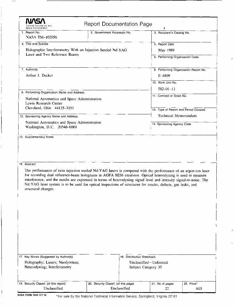
5. Abstract
The performance of twin injection seeded Nd:YAG lasers is compared with the performance of an argon-ion laser for recording dual-reference-beam holograms in AGFA 8E56 emulsion. Optical heterodyning is used to measure interference, and the results are expressed in terms of heterodyning signal level and intensity signal-to-noise. The Nd:YAG laser system is to be used for optical inspections of structures for cracks, defects, gas leaks, and structural changes.
Holography; Lasers; Neodymium; Heterodyning; Interferometry
Unclassified - Unlimited Subject Category 35
*For sale by the National Technical Information Service, Springfield, Virginia 221 61 NASA FORM 1626 OCT 86