hk06at hydraulic crimping tool - mouser.com
TRANSCRIPT
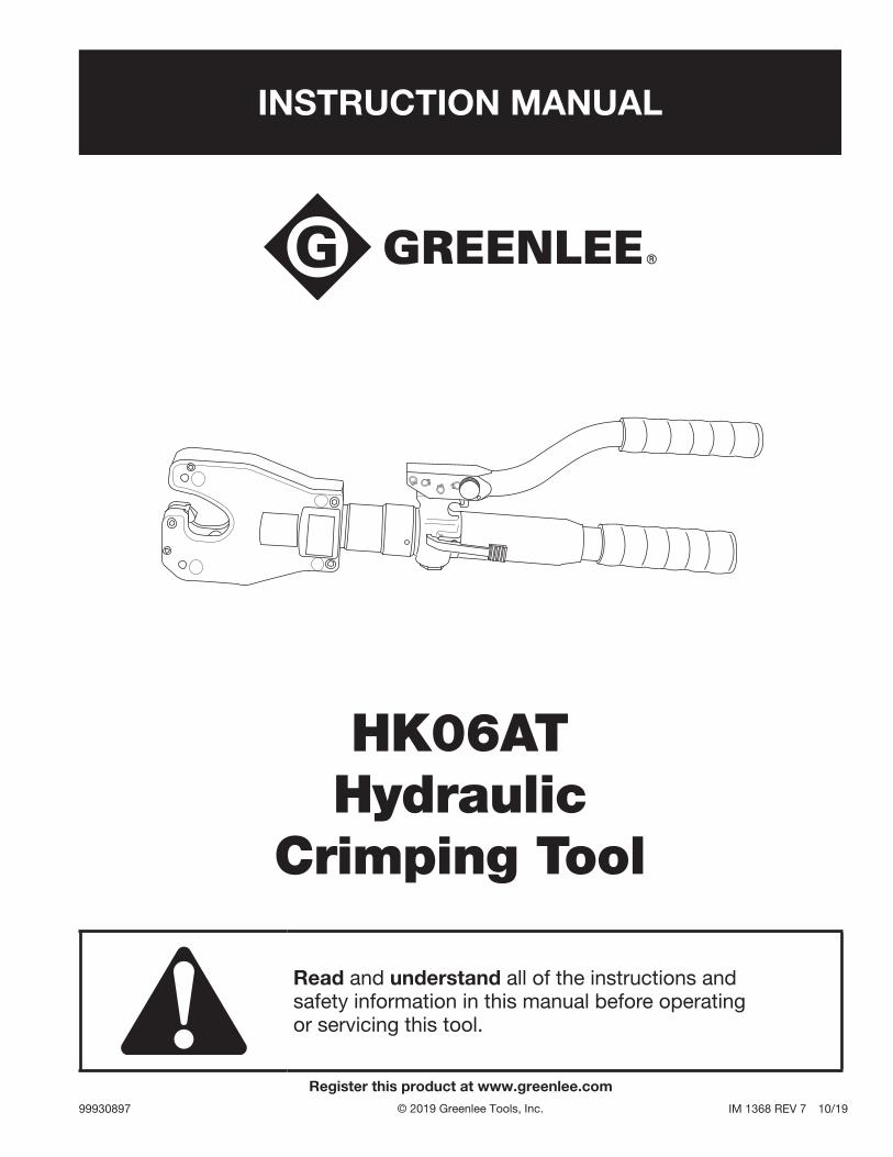
INSTRUCTION MANUAL
HK06AT Hydraulic
Crimping Tool
99930897 IM 1368 REV 7 10/19
Read and understand all of the instructions and safety information in this manual before operating or servicing this tool.
Register this product at www.greenlee.com© 2019 Greenlee Tools, Inc.
HK06AT Hydraulic Crimping Tool
Greenlee Tools, Inc. 4455 Boeing Dr. • Rockford, IL 61109-2988 USA • 815-397-70702
Description
The HK06AT Hydraulic Crimping Tool is a hand-held, self-contained, dieless crimping tool intended to crimp aluminum and copper connectors onto electrical cable.
Safety
Safety is essential in the use and maintenance of Greenlee tools and equipment. This instruction manual and any markings on the tool provide information for avoiding hazards and unsafe practices related to the use of this tool. Observe all of the safety information provided.
Purpose of this Manual
This manual is intended to familiarize all personnel with the safe operation and maintenance procedures for the following Greenlee tool:
HK06AT Hydraulic Crimping Tool
Keep this manual available to all personnel.
Replacement manuals are available upon request at no charge at www.greenlee.com.
All specifications are nominal and may change as design improvements occur. Greenlee Tools, Inc. shall not be liable for damages resulting from misapplication or misuse of its products. Blackburn is a registered trademark of Thomas & Betts.Tellus is a registered trademark of Shell Oil Company.
KEEP THIS MANUAL
Table of Contents
Description .................................................................... 2
Safety ............................................................................ 2
Purpose of this Manual ................................................. 2
Important Safety Information .....................................3–4
Identification .................................................................. 5
Specifications ................................................................ 5
Operation ....................................................................... 6
Connector Selection ...................................................... 7
Periodic Pressure Relief Valve Check............................ 7
Illustrations and Parts List ........................................8–12
HK06AT Hydraulic Crimping Tool
Greenlee Tools, Inc. 4455 Boeing Dr. • Rockford, IL 61109-2988 USA • 815-397-70703
IMPORTANT SAFETY INFORMATION
SAFETY ALERT SYMBOL
This symbol is used to call your attention to hazards or unsafe practices which could result in an injury or property damage. The signal word, defined below, indicates the severity of the hazard. The message after the signal word provides information for pre-venting or avoiding the hazard.
Immediate hazards which, if not avoided, WILL result in severe injury or death.
Hazards which, if not avoided, COULD result in severe injury or death.
Hazards or unsafe practices which, if not avoided, MAY result in injury or property damage.
Read and understand all of the instructions and safety information in this manual before operating or servicing this tool.
Failure to observe this warning could result in severe injury or death.
Electric shock hazard:
This tool is not insulated. When using this unit on or near energized electri-cal lines, use proper personal protec-tive equipment.
Failure to observe this warning could result in severe injury or death.
Wear eye protection when operating this tool.
Failure to wear eye protection could result in serious eye injury from flying debris or hydraulic oil.
Skin injection hazard:
• Do not use hands to check forleaks.
• Depressurize the hydraulic systembefore servicing.
Oil under pressure easily punctures skin causing serious injury, gan-grene, or death. If you are injured by escaping oil, seek medical attention immediately.
HK06AT Hydraulic Crimping Tool
Greenlee Tools, Inc. 4455 Boeing Dr. • Rockford, IL 61109-2988 USA • 815-397-70704
IMPORTANT SAFETY INFORMATION
An incomplete crimp can cause a fire.
• Use proper connector and cable combinations.Improper combinations can result in an incompletecrimp.
• The handle load will drop suddenly to indicate acompleted crimp. If the handle load does not dropsuddenly, the crimp is not complete.
Failure to observe these warnings could result in severe injury or death.
Inspect tool before use. Replace any worn or damaged parts. A damaged or improperly assembled tool can break and strike nearby personnel.
Failure to observe this warning could result in severe injury or death.
• This tool is intended for two-handed operation.Maintain a firm grip on both handles during opera-tion. Using this tool in any other manner can resultin injury or property damage.
• Do not operate the tool without a connector inplace. Damage to the ram or crimping tool headcan result.
Failure to observe these precautions may result in injury and property damage.
Note: Keep all decals clean and legible, and replace when necessary.
HK06AT Hydraulic Crimping Tool
Greenlee Tools, Inc. 4455 Boeing Dr. • Rockford, IL 61109-2988 USA • 815-397-70705
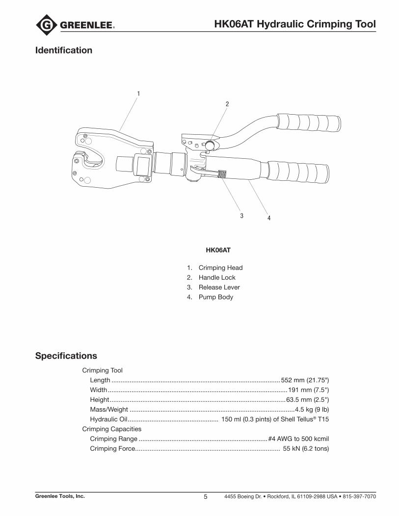
Identification
Specifications
Crimping Tool
Length .............................................................................................552 mm (21.75")Width ...................................................................................................191 mm (7.5")
Height .................................................................................................63.5 mm (2.5")
Mass/Weight ...........................................................................................4.5 kg (9 lb)
Hydraulic Oil .................................................. 150 ml (0.3 pints) of Shell Tellus® T15
Crimping Capacities
Crimping Range .......................................................................#4 AWG to 500 kcmilCrimping Force ................................................................................ 55 kN (6.2 tons)
43
2
1
HK06AT
1. Crimping Head
2. Handle Lock
3. Release Lever
4. Pump Body
HK06AT Hydraulic Crimping Tool
Greenlee Tools, Inc. 4455 Boeing Dr. • Rockford, IL 61109-2988 USA • 815-397-70706
Operation
Electric shock hazard:
This tool is not insulated. When using this unit on or near energized electri-cal lines, use proper personal protec-tive equipment.
Failure to observe this warning could result in severe injury or death.
Wear eye protection when operating this tool.
Failure to wear eye protection could result in serious eye injury from flying debris or hydraulic oil.
Skin injection hazard:
• Do not use hands to check forleaks.
• Depressurize the hydraulic systembefore servicing.
Oil under pressure easily punctures skin causing serious injury, gan-grene, or death. If you are injured by escaping oil, seek medical attention immediately.
An incomplete crimp can cause a fire.
• Use proper connector and cable combinations.Improper combinations can result in an incompletecrimp.
• The handle load will drop suddenly to indicate acompleted crimp. If the handle load does not dropsuddenly, the crimp is not complete.
Failure to observe these warnings could result in severe injury or death.
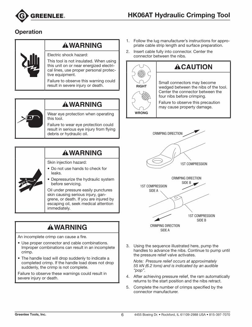
1. Follow the lug manufacturer’s instructions for appro-priate cable strip length and surface prep aration.
2. Insert cable fully into connector. Center the con nector between the nibs.
RIGHT
WRONG
Small connectors may become wedged between the nibs of the tool. Center the connector between the four nibs before crimping.
Failure to observe this precaution may cause property damage.
CRIMPING DIRECTION
1ST COMPRESSION
CRIMPING DIRECTIONSIDE A
CRIMPING DIRECTIONSIDE B
1ST COMPRESSIONSIDE A
1ST COMPRESSIONSIDE B
3. Using the sequence illustrated here, pump thehandles to advance the nibs. Continue to pump untilthe pressure relief valve activates.
Note: Pressure relief occurs at approximately55 kN (6.2 tons) and is indicated by an audible“pop”.
4. After achieving pressure relief, the ram automaticallyreturns to the start position and the nibs retract.
5. Complete the number of crimps specified by theconnector manufacturer.
HK06AT Hydraulic Crimping Tool
Greenlee Tools, Inc. 4455 Boeing Dr. • Rockford, IL 61109-2988 USA • 815-397-70707
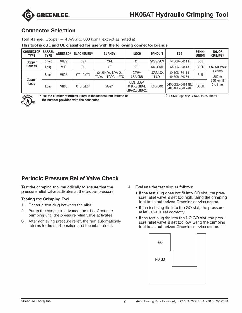
Periodic Pressure Relief Valve Check
Test the crimping tool periodically to ensure that the pressure relief valve activates at the proper pressure.
Testing the Crimping Tool
1. Center a test slug between the nibs.
2. Pump the handle to advance the nibs. Continuepumping until the pressure relief valve activates.
3. After achieving pressure relief, the ram automaticallyreturns to the start position and the nibs retract.
4. Evaluate the test slug as follows:
• If the test slug does not fit into GO slot, the pres-sure relief valve is set too high. Send the crimpingtool to an authorized Greenlee service center.
• If the test slug fits into the GO slot, the pressurerelief valve is set correctly.
• If the test slug fits into the NO GO slot, the pres-sure relief valve is set too low. Send the crimpingtool to an authorized Greenlee service center.
GO
NO GO
Connector Selection
Tool Range: Copper — 4 AWG to 500 kcmil (except as noted ∆)
This tool is cUL and UL classified for use with the following connector brands:
CONNECTOR TYPE
BARREL TYPE ANDERSON BLACKBURN® BURNDY ILSCO PANDUIT T&B PENN-
UNIONNO. OF
CRIMPS*
Copper Splices
Short VHSS CSP YS-L CT SCSS/SCS 54506–54518 BCU
4 to 4/0 AWG: 1 crimp
250 to 500 kcmil: 2 crimps
Long VHS CU YS CTL SCL/SCH 54806–54818 BBCU
Copper Lugs
Short VHCS CTL-2/CTL YA-2LN/YA-L/YA-2L YA/YA-L-TC/YA-L-2TC
CSW∆ CRA/CRB
LCAS/LCA LCD
54106–54118 54206–54286 BLU
Long VHCL CTL-L/LCN YA-2NCLN, CLW∆
CRA-L/CRB-L CRA-2L/CRB-2L
LCB/LCC 54906BE–54919BE 54854BE–54876BE BBLU
*Use the number of crimps listed in the last column instead ofthe number provided with the connector.
∆ ILSCO Capacity: 4 AWG to 250 kcmil
HK06AT Hydraulic Crimping Tool
Greenlee Tools, Inc. 4455 Boeing Dr. • Rockford, IL 61109-2988 USA • 815-397-70708
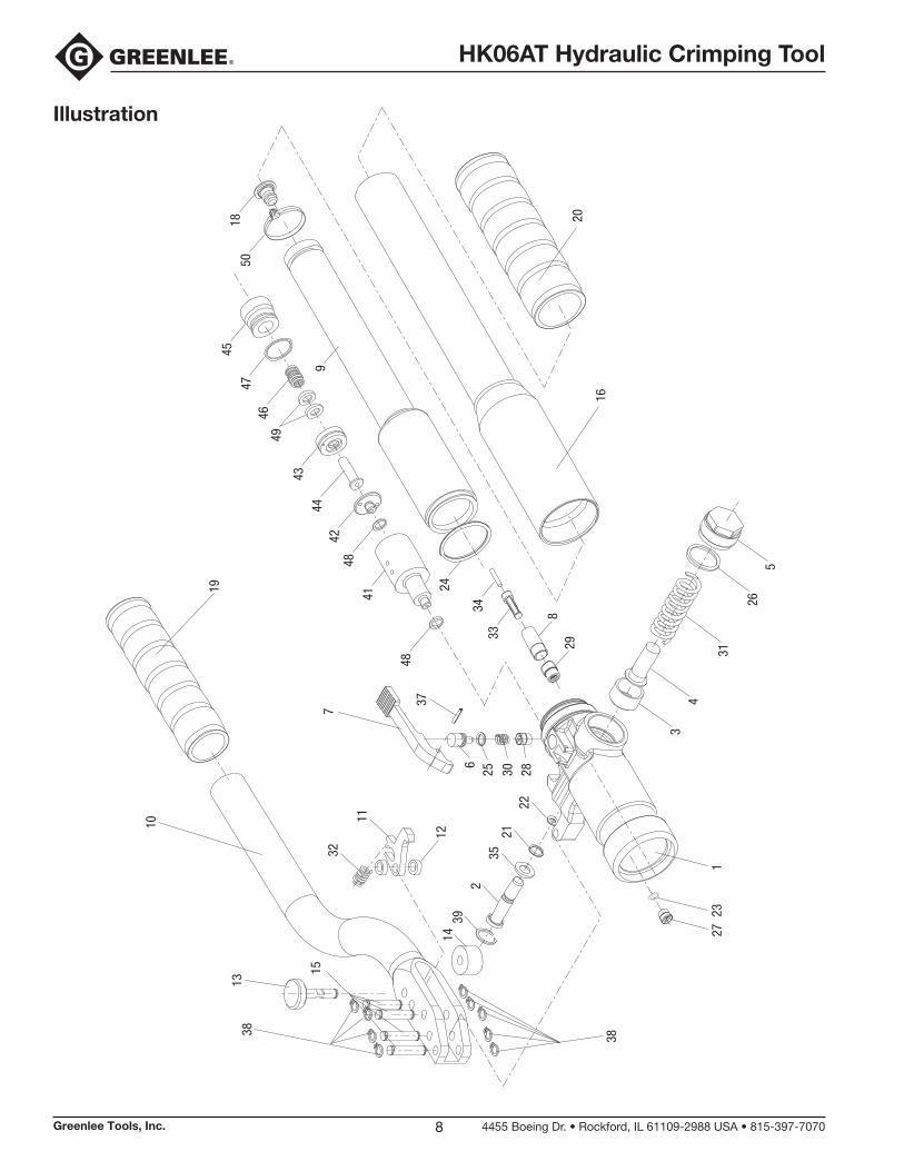
Illustration
3813
15
38
2830256
26
16
20
37
7
271
23
10
19
9
45
4746
49
4344
4248
41
48
34
24
5018
932
12
11
22
33
829
5
31
43
2135
2
1439
HK06AT Hydraulic Crimping Tool
Greenlee Tools, Inc. 4455 Boeing Dr. • Rockford, IL 61109-2988 USA • 815-397-70709
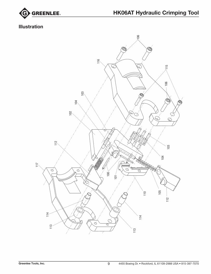
Illustration
112
102
104
103
106
115
106
103
104
105
110
114
11311
311
4
112
117
116
100
101

HK06AT Hydraulic Crimping Tool
Greenlee Tools, Inc. 4455 Boeing Dr. • Rockford, IL 61109-2988 USA • 815-397-707010
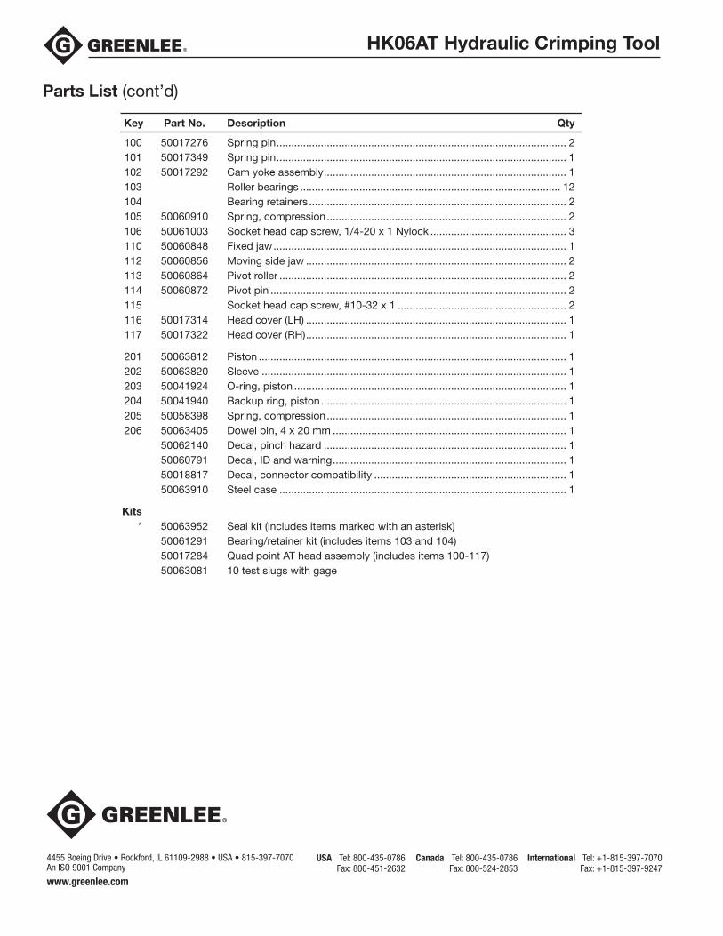
Illustration
205
201
204
203
202
206
HK06AT Hydraulic Crimping Tool
Greenlee Tools, Inc. 4455 Boeing Dr. • Rockford, IL 61109-2988 USA • 815-397-707011
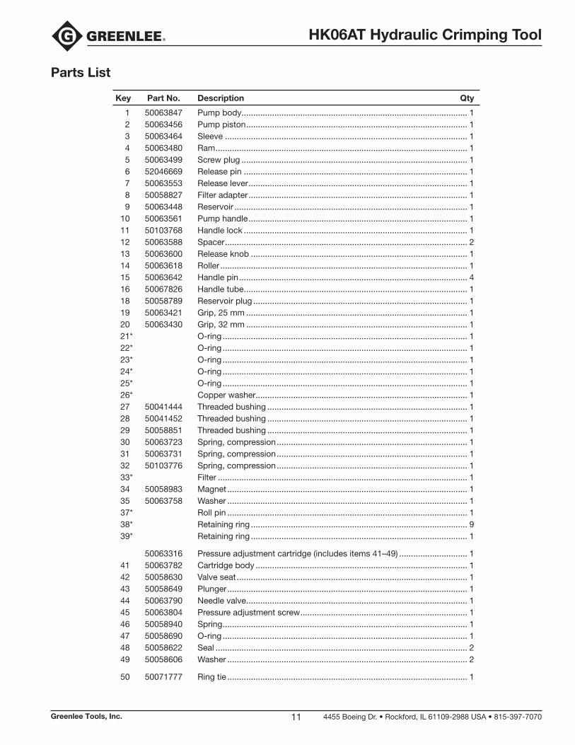
Parts List
Key Part No. Description Qty
1 50063847 Pump body................................................................................................ 12 50063456 Pump piston .............................................................................................. 13 50063464 Sleeve ....................................................................................................... 14 50063480 Ram ........................................................................................................... 15 50063499 Screw plug ................................................................................................ 16 52046669 Release pin ............................................................................................... 17 50063553 Release lever ............................................................................................. 18 50058827 Filter adapter ............................................................................................. 19 50063448 Reservoir ................................................................................................... 1
10 50063561 Pump handle ............................................................................................. 111 50103768 Handle lock ............................................................................................... 112 50063588 Spacer ....................................................................................................... 213 50063600 Release knob ............................................................................................ 114 50063618 Roller ......................................................................................................... 115 50063642 Handle pin ................................................................................................. 416 50067826 Handle tube ............................................................................................... 118 50058789 Reservoir plug ........................................................................................... 119 50063421 Grip, 25 mm .............................................................................................. 120 50063430 Grip, 32 mm .............................................................................................. 121* O-ring ........................................................................................................ 122* O-ring ........................................................................................................ 123* O-ring ........................................................................................................ 124* O-ring ........................................................................................................ 125* O-ring ........................................................................................................ 126* Copper washer .......................................................................................... 127 50041444 Threaded bushing ..................................................................................... 128 50041452 Threaded bushing ..................................................................................... 129 50058851 Threaded bushing ..................................................................................... 130 50063723 Spring, compression ................................................................................. 131 50063731 Spring, compression ................................................................................. 132 50103776 Spring, compression ................................................................................. 133* Filter .......................................................................................................... 134 50058983 Magnet ...................................................................................................... 135 50063758 Washer ...................................................................................................... 137* Roll pin ...................................................................................................... 138* Retaining ring ............................................................................................ 939* Retaining ring ............................................................................................ 1
50063316 Pressure adjustment cartridge (includes items 41–49) ............................. 141 50063782 Cartridge body .......................................................................................... 142 50058630 Valve seat .................................................................................................. 143 50058649 Plunger ...................................................................................................... 144 50063790 Needle valve .............................................................................................. 145 50063804 Pressure adjustment screw ....................................................................... 146 50058940 Spring ........................................................................................................ 147 50058690 O-ring ........................................................................................................ 148 50058622 Seal ........................................................................................................... 249 50058606 Washer ...................................................................................................... 2
50 50071777 Ring tie ...................................................................................................... 1
HK06AT Hydraulic Crimping Tool
100 50017276 Spring pin .................................................................................................. 2101 50017349 Spring pin .................................................................................................. 1102 50017292 Cam yoke assembly .................................................................................. 1103 Roller bearings ........................................................................................ 12104 Bearing retainers ....................................................................................... 2105 50060910 Spring, compression ................................................................................. 2106 50061003 Socket head cap screw, 1/4-20 x 1 Nylock .............................................. 3110 50060848 Fixed jaw ................................................................................................... 1112 50060856 Moving side jaw ........................................................................................ 2113 50060864 Pivot roller ................................................................................................. 2114 50060872 Pivot pin .................................................................................................... 2115 Socket head cap screw, #10-32 x 1 ......................................................... 2116 50017314 Head cover (LH) ........................................................................................ 1117 50017322 Head cover (RH) ........................................................................................ 1
201 50063812 Piston ........................................................................................................ 1202 50063820 Sleeve ....................................................................................................... 1203 50041924 O-ring, piston ............................................................................................ 1204 50041940 Backup ring, piston ................................................................................... 1205 50058398 Spring, compression ................................................................................. 1206 50063405 Dowel pin, 4 x 20 mm ............................................................................... 1
50062140 Decal, pinch hazard .................................................................................. 150060791 Decal, ID and warning ............................................................................... 150018817 Decal, connector compatibility ................................................................. 150063910 Steel case ................................................................................................. 1
Kits* 50063952 Seal kit (includes items marked with an asterisk)
50061291 Bearing/retainer kit (includes items 103 and 104)50017284 Quad point AT head assembly (includes items 100-117)50063081 10 test slugs with gage
Key Part No. Description Qty
Parts List (cont’d)
USA Tel: 800-435-0786Fax: 800-451-2632
Canada Tel: 800-435-0786Fax: 800-524-2853
International Tel: +1-815-397-7070Fax: +1-815-397-9247
4455 Boeing Drive • Rockford, IL 61109-2988 • USA • 815-397-7070 An ISO 9001 Company
www.greenlee.com

Mouser Electronics
Authorized Distributor
Click to View Pricing, Inventory, Delivery & Lifecycle Information: Greenlee:
50063448 50063952