ilc-12-n hydraulic crimping tool
TRANSCRIPT
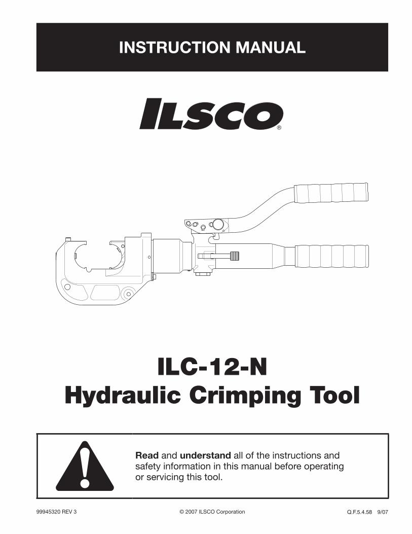
INSTRUCTION MANUAL
ILC-12-N Hydraulic Crimping Tool
Read and understand all of the instructions and safety information in this manual before operating or servicing this tool.
99945320 REV 3 © 2007 ILSCO Corporation Q.F.5.4.58 9/07

ILC-12-N Hydraulic Crimping Tool
ILSCO Corporation 4730 Madison Rd. • Cincinnati, OH 45227-1426 • 800/776-97752
Description
The ILC-12-N Hydraulic Crimping Tool is a hand-held, self-contained crimping tool intended to crimp alumi-num and copper connectors onto electrical cable. It uses industry standard 12-ton U-type dies, purchased separately.
Safety
Safety is essential in the use and maintenance of ILSCO tools and equipment. This manual and any markings on the tool provide information for avoiding hazards and unsafe practices related to the use of this tool. Observe all of the safety information provided.
Purpose of this Manual
This manual is intended to familiarize all personnel with the safe operation and maintenance procedures for the following ILSCO tool:
ILC-12-N Hydraulic Crimping Tool
Keep this manual available to all personnel.
Replacement manuals are available upon request at no charge.
Warranty and Service
ILSCO warrants this tool to the original purchaser for a period of one year from the date of purchase, provided the tool is operated, maintained and used in accordance with ILSCO’s written instructions. Ordinary wear and tear, damage from abuse, neglect or alterations are not covered by this warranty. This warranty is null and void if instructions and operating procedures are not fol-lowed. Contact ILSCO for all warranty and service issues at 800-776-9775.
Tellus is a registered trademark of Shell Oil Company.
KEEP THIS MANUAL
Table of Contents
Description .................................................................... 2
Safety ............................................................................ 2
Purpose of this Manual ................................................. 2
Warranty and Service .................................................... 2
Important Safety Information .....................................3–4
Identification .................................................................. 5
Specifications ................................................................ 5
Operation ....................................................................... 6
Periodic Pressure Relief Valve Check............................ 8
Illustrations .................................................................8–9
Parts List ................................................................10–11
ILC-12-N Hydraulic Crimping Tool
ILSCO Corporation 4730 Madison Rd. • Cincinnati, OH 45227-1426 • 800/776-97753
IMPORTANT SAFETY INFORMATION
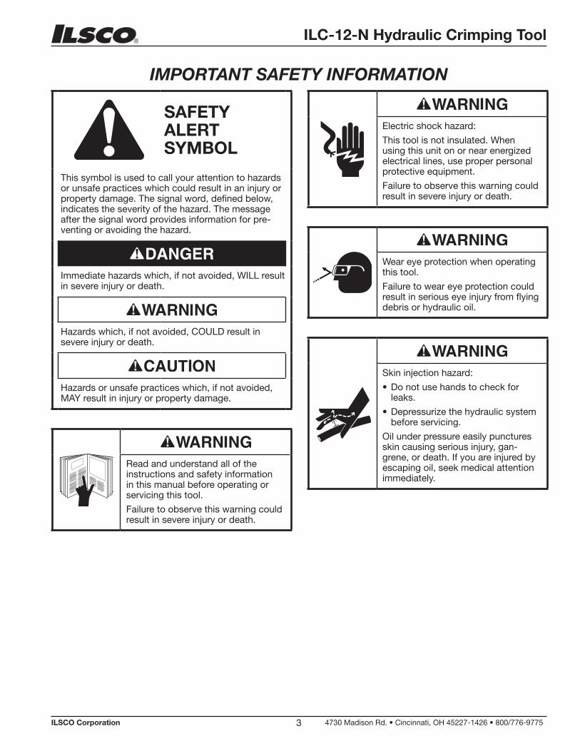
SAFETY ALERT SYMBOL
This symbol is used to call your attention to hazards or unsafe practices which could result in an injury or property damage. The signal word, defined below, indicates the severity of the hazard. The message after the signal word provides information for pre-venting or avoiding the hazard.
Immediate hazards which, if not avoided, WILL result in severe injury or death.
Hazards which, if not avoided, COULD result in severe injury or death.
Hazards or unsafe practices which, if not avoided, MAY result in injury or property damage.
Read and understand all of the instructions and safety information in this manual before operating or servicing this tool.
Failure to observe this warning could result in severe injury or death.
Electric shock hazard:
This tool is not insulated. When using this unit on or near energized electrical lines, use proper personal protective equipment.
Failure to observe this warning could result in severe injury or death.
Wear eye protection when operating this tool.
Failure to wear eye protection could result in serious eye injury from flying debris or hydraulic oil.
Skin injection hazard:
Do not use hands to check for leaks.
Depressurize the hydraulic system before servicing.
Oil under pressure easily punctures skin causing serious injury, gan-grene, or death. If you are injured by escaping oil, seek medical attention immediately.
•
•
ILC-12-N Hydraulic Crimping Tool
ILSCO Corporation 4730 Madison Rd. • Cincinnati, OH 45227-1426 • 800/776-97754
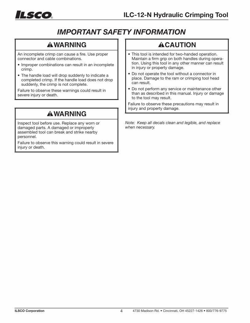
IMPORTANT SAFETY INFORMATION
An incomplete crimp can cause a fire. Use proper connector and cable combinations.
Improper combinations can result in an incomplete crimp.
The handle load will drop suddenly to indicate a completed crimp. If the handle load does not drop suddenly, the crimp is not complete.
Failure to observe these warnings could result in severe injury or death.
•
•
Inspect tool before use. Replace any worn or damaged parts. A damaged or improperly assembled tool can break and strike nearby personnel.
Failure to observe this warning could result in severe injury or death.
This tool is intended for two-handed operation. Maintain a firm grip on both handles during opera-tion. Using this tool in any other manner can result in injury or property damage.
Do not operate the tool without a connector in place. Damage to the ram or crimping tool head can result.
Do not perform any service or maintenance other than as described in this manual. Injury or damage to the tool may result.
Failure to observe these precautions may result in injury and property damage.
•
•
•
Note: Keep all decals clean and legible, and replace when necessary.

ILC-12-N Hydraulic Crimping Tool
ILSCO Corporation 4730 Madison Rd. • Cincinnati, OH 45227-1426 • 800/776-97755
Identification
1 2
6
4
3
5
Specifications
Crimping Tool
Length .............................................................................................552 mm (21.75")
Width .....................................................................................................74 mm (2.9")
Mass/Weight ......................................................................................6.1 kg (13.4 lb)
Hydraulic Oil ......................................................50 ml (0.1 pint) of Shell Tellus® T 15
Crimping Capacities
Crimping Range ........................................................................ 8 AWG to 750 kcmil
Crimping Force ................................................................................ 106 kN (12 tons)
ILC-12-N
Die Release Button
Die Release Button
Handle
1.
2.
3.
Return Lever
Handle with Reservoir
Crimping Head
4.
5.
6.

ILC-12-N Hydraulic Crimping Tool
ILSCO Corporation 4730 Madison Rd. • Cincinnati, OH 45227-1426 • 800/776-97756
Operation
Electric shock hazard:
This tool is not insulated. When using this unit on or near energized electrical lines, use proper personal protective equipment.
Failure to observe this warning could result in severe injury or death.
Wear eye protection when operating this tool.
Failure to wear eye protection could result in serious eye injury from flying debris or hydraulic oil.
Skin injection hazard:
Do not use hands to check for leaks.
Depressurize the hydraulic system before servicing.
Oil under pressure easily punctures skin causing serious injury, gan-grene, or death. If you are injured by escaping oil, seek medical attention immediately.
•
•
An incomplete crimp can cause a fire. Use proper connector and cable combinations.
Improper combinations can result in an incomplete crimp.
The handle load will drop suddenly to indicate a completed crimp. If the handle load does not drop suddenly, the crimp is not complete.
Failure to observe these warnings could result in severe injury or death.
•
•
1. Clean the die seat area.
2. Install the proper size and type of crimping dies.
3. Press the release button on the C-head and slide one of the die halves into the jaw. Release the button and slide the die half until the retainer snaps and locks the die into place.
4. Press the release button on the ram body (located in the cutout) and slide the other die half in. Release the button and slide the die half until the retainer snaps and locks the die into place.
5. Follow the instructions in the ILSCO stuffer sheet for appropriate cable strip length and surface preparation.
6. Insert cable fully into connector and center the con-nector between the dies.
7. Using the sequence illustrated here, pump the handles to advance the dies. Continue to pump until the pressure relief valve activates.
Note: Pressure relief occurs at approximately 106 kN (12 tons) and is indicated by an audible “pop”.
8. After achieving pressure relief, the ram automatically returns to the start position and the dies retract.
9. Complete the number of crimps specified in the ILSCO stuffer sheet.
10. Remove the connector from the crimping tool.
11. Press the trigger lock upward to lock the trigger.
Note: After completing the last crimp on an alumi-num connector, wipe off the excess oxide inhibitor.
CRIMPING DIRECTION
1ST COMPRESSION
CRIMPING DIRECTIONSIDE A
CRIMPING DIRECTIONSIDE B
1ST COMPRESSIONSIDE A
1ST COMPRESSIONSIDE B

ILC-12-N Hydraulic Crimping Tool
ILSCO Corporation 4730 Madison Rd. • Cincinnati, OH 45227-1426 • 800/776-97757
Periodic Pressure Relief Valve Check
Pinch points:
Keep hands away from closing dies.
Failure to observe this warning could result in severe injury or death.
The crimping tool’s relief valve may require occasional adjustment. To determine whether this adjustment is necessary, periodically test the crimping tool with a load cell.
1. Insert the test dies into the tool (refer to steps 3 and 4 under “Operation” in this manual). Position the load cell so that the load cell piston is centered between the two test dies.
2. Pump the lever until the crimping tool achieves pressure relief and note the position of the needle when the pressure relief is achieved. The needle should indicate the “12T” range. If the needle is outside of this range, send the crimping tool to ILSCO.
Note: Some types of load cells have a different ratio between the area of the tool and the area of the load cell. The appropriate corresponding pressure range depends upon this ratio.

ILC-12-N Hydraulic Crimping Tool
ILSCO Corporation 4730 Madison Rd. • Cincinnati, OH 45227-1426 • 800/776-97758
36
34
10
17
13
14
36
15
37
2
3319
20
2549
21
1
3
4
29
27
6
7
23
35
38
28 26
8
31
32
22
9
18
48
16
24
5
1211
30
Illustration

ILC-12-N Hydraulic Crimping Tool
ILSCO Corporation 4730 Madison Rd. • Cincinnati, OH 45227-1426 • 800/776-97759
Illustration
203
202
201
200
204
102
103
107
106
104
105
108
114
11211
1
120
123
115
125
122
101
126
121
124
113

ILC-12-N Hydraulic Crimping Tool
ILSCO Corporation 4730 Madison Rd. • Cincinnati, OH 45227-1426 • 800/776-977510
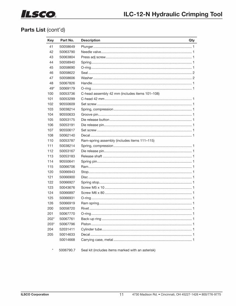
Parts List
Key Part No. Description Qty
1 50067800 Body .......................................................................................................... 1
2 50063456 Pump piston .............................................................................................. 1
3 50063464 Sleeve ....................................................................................................... 1
4 50063480 Ram ........................................................................................................... 1
5 50063499 Screw plug ................................................................................................ 1
6 50063545 Release pin ............................................................................................... 1
7 50063553 Release lever ............................................................................................. 1
8 50058827 Filter adapter ............................................................................................. 1
9 50063448 Reservoir ................................................................................................... 1
10 50063561 Pump lever ................................................................................................ 1
11 50063570 Handle lock ............................................................................................... 1
12 50063588 Spacer ....................................................................................................... 2
13 50063600 Release knob ............................................................................................ 1
14 50063618 Roller ......................................................................................................... 1
15 50063642 Handle pin ................................................................................................. 4
16 50058789 Reservoir plug ........................................................................................... 1
17 50063421 Grip 25 mm ............................................................................................... 1
18 50063430 Grip 32 mm ............................................................................................... 1
19* 50063685 O-ring ........................................................................................................ 1
20* 50063693 O-ring ........................................................................................................ 1
21* 50041436 O-ring ........................................................................................................ 1
22* 50058860 O-ring ........................................................................................................ 1
23* 50063707 O-ring ........................................................................................................ 1
24* 50063715 Copper washer .......................................................................................... 1
25 50041444 Threaded bushing ..................................................................................... 1
26 50041452 Threaded bushing ..................................................................................... 1
27 50058851 Threaded bushing ..................................................................................... 1
28 50063723 Spring, compression ................................................................................. 1
29 50063731 Spring, compression ................................................................................. 1
30 50063740 Spring, extension ...................................................................................... 1
31* 50058800 Filter .......................................................................................................... 1
32 50058983 Magnet ...................................................................................................... 1
33 50063758 Washer ...................................................................................................... 1
34 50067818 Roll, pin ..................................................................................................... 1
35* 50063774 Roll, pin ..................................................................................................... 1
36* 50058762 Retaining ring ............................................................................................ 9
37* 50063359 Retaining ring ............................................................................................ 1
38 50063316 Pressure adj cartridge (includes items 39–47) .......................................... 1
39 50063782 Cartridge body .......................................................................................... 1
40 50058630 Valve seat .................................................................................................. 1
ILC-12-N Hydraulic Crimping Tool
ILSCO Corporation 4730 Madison Rd. • Cincinnati, OH 45227-1426 • 800/776-977511
41 50058649 Plunger ...................................................................................................... 1
42 50063790 Needle valve .............................................................................................. 1
43 50063804 Press adj screw ......................................................................................... 1
44 50058940 Spring ........................................................................................................ 1
45 50058690 O-ring ........................................................................................................ 1
46 50058622 Seal ........................................................................................................... 2
47 50058606 Washer ...................................................................................................... 2
48 50067826 Handle ....................................................................................................... 1
49* 50069179 O-ring ........................................................................................................ 1
100 50053736 C-head assembly 42 mm (includes items 101–108)
101 50053299 C-head 42 mm .......................................................................................... 1
102 90550609 Set screw .................................................................................................. 1
103 50038214 Spring, compression ................................................................................. 1
104 90550633 Groove pin................................................................................................. 1
105 50053175 Die release button ..................................................................................... 1
106 50053191 Die release pin........................................................................................... 1
107 90550617 Set screw .................................................................................................. 1
108 50062140 Decal ......................................................................................................... 1
110 50053787 Ram-spring assembly (includes items 111–115)
111 50038214 Spring, compression ................................................................................. 1
112 50053167 Die release pin........................................................................................... 1
113 50053183 Release shaft ............................................................................................ 1
114 90550641 Spring pin .................................................................................................. 1
115 50066706 Ram ........................................................................................................... 1
120 50066943 Stop........................................................................................................... 1
121 50066900 Disc ........................................................................................................... 1
122 50066927 Spring stop................................................................................................ 1
123 50043676 Screw M5 x 10 .......................................................................................... 1
124 50066897 Screw M6 x 80 .......................................................................................... 1
125 50066931 O-ring ........................................................................................................ 1
126 50066919 Ram spring ................................................................................................ 1
200 50058720 Rivet .......................................................................................................... 1
201 50067770 O-ring ........................................................................................................ 1
202* 50067761 Back-up ring ............................................................................................. 1
203* 50067796 Piston ........................................................................................................ 1
204 52031411 Cylinder tube ............................................................................................. 1
205 50014633 Decal ......................................................................................................... 1
50014668 Carrying case, metal ................................................................................. 1
* 5006790.7 Seal kit (includes items marked with an asterisk)
Key Part No. Description Qty
Parts List (cont’d)

U.S. TECHNICAL SUPPORT1-800-776-9775
ILSCO Corporation • 4730 Madison Road, Cincinnati, Ohio 45227-1426Phone (800) 776-9775, (513) 533-6200 • Fax (513) 871-4084E-mail: [email protected] • Web site: http://www.ilsco.com
Printed in the USA