hitachi wireless ip-5000 phone...
TRANSCRIPT

Note: ShoreTel highly recommends using the Hitachi handset in a “Find Me / Follow Me” type configuration. Currently ShoreTel does not support “SIP Extensions”, ShoreTel provides this application note as a work around when used with “SIP Trunks”. Please keep in mind by using an “end point” device with “SIP Trunks” will have limitations.
Hitachi Wireless IP-5000 Phone (SIP) Wireless communication is a powerful solution which provides users the convenience of having their voice features available to them at any time and the freedom and mobility of using these features at any point on the wireless network. This application note provides the details on adding the Hitachi Wireless IP 5000 (SIP) handsets to the ShoreTel IP phone system.
™Application Note
ST-0132 February 5, 2007
Overview
This document provides details on the Hitachi Wireless IP-5000 handset and describes how to integrate this handset into the ShoreTel IP Phone System. The document focuses on the configuration procedures needed to set-up the Hitachi handset for the ShoreTel system and the configura-tion needed on the ShoreTel system to support the Hitachi handset.
OverviewFeatures and Benefits.Vendor Overview and ContactHitachi Wireless IP-5000 Information Features Technical Specifications
Architecture OverviewRequirements, Certification and Limitations ShoreTel Requirements Hitachi Wireless IP-5000 Requirements WiFi (Wireless) Network Requirements and Recommendations Certification Known Limitations Interaction with “911” Support
Version SupportConfiguration OverviewShoreTel Configuration ShoreTel System Settings — General Switch Settings — Allocating Ports for SIP Trunks: ShoreTel System Settings — Trunk Groups: ShoreTel System Settings — Individual Trunks
Hitachi Wireless IP-5000 Configuration Hitachi handset connection to WiFi Network Retrieving handset IP Address Connecting to the handset web interface Manual Web Interface Configuration Software Version Verification Web Based Configuration System RTP RTCP SIP Configuration Transfer Conference DTMF Tone Type System Setup Network Setup SIP Registration User Account Server Settings Network Profile
Appendix “A” — User.ini exampleDocument and Software CopyrightsTrademarksCompany Information
171717171717181919202121 21212222
22
22
23
24
28
28
28
1
2
2
233
4
7777
81010
11
11
1111121314
Table of Contents

ShoreTel IP-5000 Phone (SIP): Hitachi Wireless Application Note—Page 2
Resellers who want to start selling this solution should contact:ABP Technology (Hitachi distributor) www.abptech.comNorma Adams, VAR coordinator [email protected] +1.972.831.1600 x 121
Hitachi Wireless IP-5000 Information
Wireless IP-5000 is an advanced wireless (IEEE 802.11b) IP phone that allows users to achieve perfect voice communi-cation over an IEEE 802.11b wireless IP network. Not only does the Wireless IP-5000 support all of the conveniences and functions of a digital phone, it also perfectly integrates all of the merits and features of analog and IP phones over the data communication system.
Wireless IP-5000 provides your own private mobile network for your workplace so you no longer have to miss important calls as you move around your work site. Its compact and light body fits into your pocket, so you can use it anytime and anywhere. It can even be integrated into your existing phone system to provide lower-cost internal and external voice communication.
As voice signals are automatically compressed using audio CODECs, they can be transmitted over a low bandwidth without interference from other data signals. Furthermore, to provide consistent superior voice quality over varying and congested IP network conditions, the Wireless IP-5000 is equipped with advanced Quality of Service (QoS) technolo-gies such as CODEC negotiation, enhanced jitter buffering technology, and packet delay compensation.
Document covers the following topics:
Features and BenefitsVendor Overview and ContactsHitachi Product InformationSystem Requirements, Certification and LimitationsShoreTel ConfigurationHitachi Configuration
This application note provides the ShoreTel-specific configu-ration instructions. Important Hitachi configuration steps are defined, however this application note does not cover all the general Hitachi handset installation and setup instruc-tions. For general information, please refer to the Hitachi Wireless IP-5000 handsets product documentation. This application note also does not address detailed WiFi network setup or installation.
Features and Benefits
The integration of wireless WiFi handsets leverages the power and cost effectiveness of ShoreTel’s VoIP system along with the freedom of wireless mobility. The ShoreTel system enables cost effectiveness through the reduced costs of operation and maintenance along with the reduced call costs of VoIP communication.
The use of wireless handsets allows the convenience of placing calls anywhere within the WLAN and provides the users the power of having their calling features available at any time within WLAN. The combination of the ShoreTel’s VoIP network and the Hitachi handset is a high value compelling proposition.
Vendor Overview and Contact
General information can be obtained from ABP Technology (distributor) at the following URL: http://www.abptech.com/mainpages/products/HCL-WirelessIP5000.html
Latest documentation and Firmware can be located at (password proctected): http://www.abptech.com/mainpages/support/hitachi_downloads.html
Support: [email protected]
Info: [email protected]
Partners: partners@abptech
General Sales Contact:ABP Technology 1850 Crown Dr. Ste. 1112 Farmers Branch (Dallas metro), TX - 75234 972-831-1600 / [email protected] http://www.abptech.com/
••••••
Model Number: WLAN IP PhonePart Number: Wireless IP 5000Approximate list price: $355

ShoreTel IP-5000 Phone (SIP): Hitachi Wireless Application Note—Page 3
The Wireless IP-5000 Wireless VoIP phone comes with an 8 Line LCD Display. This phone is ideal for those who want the power and cost efficiencies of VoIP but also love the freedom of wireless. All the commonly used features needed for day-to-day business are accessible directly from the phone such as:
Features
Dialed Number Display Calling Time Display Caller ID Display Mute, Hold Call Waiting Indication Instant Message & Voicemail Message Indicator (Not supported at this time with ShoreTel)Phone book Extension Number DisplayDial Tone Distinctive RingsSpeed DialRedialCall Pick UpCall HistoryMissed calls indicator Presence (Not supported at this time with ShoreTel)Short Message (IM: Instant Message)Stand-by DisplaySignal Level/Battery LevelDate/ Day Of The WeekTimeSilent Display/Vibration DisplayAlarm FunctionPC Connection by USBEar Phone/Mic English /Japanese User Friendly Graphical Menu
Technical Specifications
Hardware Dimensions: (H x W x T): 127 x 43 x 19.2 [mm] Weight: 102 [gr.] Display: 8 line, 10 digits (2-byte characters) LCD 128x128 pixel-graphical display with 4 Gray; Dot Size (WxH): 0.18 x 0.22mm; Dot Pitch (WxH): 0.19 x 0.23mm; Active Area (WxH): 24.31 x 29.43mm; FSTN GlassOperating Temperature: 0~45 C / Storage Temperature: -25~70 CButtons: Two Soft Key & 4 Directional Stick Key; Volume Control Key; Keypad Lock Key; Send/End/Cancel Key
Wireless LAN IEEE 802.11b CSMA/CA Direct Sequence Spread Spectrum 11/5.5/2/1Mbps 2.400-2.497GHzVoIP SIP v2.0 Coding: G.711 u / A-Law / Micro-Law, G.729A Acoustic Echo Cancellation (to be supported)Networking: IPv4, TFTP, DNS DHCP Client NAT Transversal; Static NAT, uPnP, STUN QoS: Standard IEEE802.11b DiffServ/IP Precedence; IEEE 802.11e (to be supported)Security: WEP (64bit/128bit/256bit) 802.1x (MD5/EAP-TLS) Secure RTP (to be supported) WEB based UAM Management: SNMP Sys log HTTP PING (to check if IP packet has been delivered to a designated address) Function for searching wireless access points Function for measuring radio strengthStandard Accessories: Charging Stand AC Adapter Battery: 1,350mA Extended Li-lon Battery (3.1 / 55 hours)
Optional Accessories: USB cable for PC connection Wireless IP Manager

ShoreTel IP-5000 Phone (SIP): Hitachi Wireless Application Note—Page 4
Architecture OverviewThe following is a diagram of the solution architecture showing the integration between the Hitachi Wireless IP-
SIP devices are being implemented on the ShoreTel System with SIP trunks. The ShoreTel system will use outbound call routing for the SIP devices. There are various ways to handle the call routing for the SIP devices. The following drawings depict different call routing designs:
Route the call with DID (Direct Inward Dial) or DNIS (Dialed Number Identification Service) directly to the Hitachi Wireless IP-5000 extension. In this configuration tandem trunking is enabled and off system extensions are defined in the trunk group (trunk group setup instructions below). Shown in the drawing is a snapshot of the “Edit ShoreGear Switch” screen indicating the selection of SIP trunks.
1.
5000 handset and the ShoreTel System:
ShoreWareDirector
Hitachi WIP-5000
IP
ShoreGear Switch(Proxy/Registrar)
WirelessAccess Point
1 2 3 4 5 6 7 8
LAN 1 LAN 2 MANT EXT 5
SIP Media
MGCP
Hitachi WIP-5000
Edit ShoreGear Switch Screen Snapshot
T1 ShoreGear Switch
ShoreTel System
(Hosting SIP Trunks)
PSTN

ShoreTel IP-5000 Phone (SIP): Hitachi Wireless Application Note—Page 5
Hitachi WIP-5000
Edit ShoreGear Switch Screen Snapshot
ShoreGear Switch
ShoreTelIP Phone
SIP Off-Extension
ShoreTel System
(Hosting SIP Trunks)
2. Routing an Internally dialed extension to the Hitachi Wireless IP-5000 extension (off system extensions are
defined in the trunk group). The selection of SIP trunks is shown again in the snapshot of the “Edit ShoreGear Switch” screen.
3. Routing through the Auto Attendant can be accom-plished in two ways.
a. Program “Multiple digits” field in menu to “Go to extension” operation for routing to Hitachi Wireless IP-5000 extension.
b. Program digit “0” to “Go to extension” operation for routing to Operator extension. Operator will have to transfer the call to the Hitachi Wireless IP-5000 extension.
Hitachi WIP-5000T1
PRI
DID & DNIS
ShoreGear Switch
ShoreGear Server
SIP Off-system Extension
ShoreTel System
(Hosting SIP Trunks)
PSTN
AutoAttendant

ShoreTel IP-5000 Phone (SIP): Hitachi Wireless Application Note—Page 6
4. Routing through Individual User Extension with the Call Handling Mode set to forward (external destination) enter
Hitachi Wireless IP-5000 extension.
Hitachi WIP-5000T1
PRI
DID & DNIS
ShoreGear Switch
SIP Off-system Extension
ShoreTel System
(Hosting SIP Trunks)
Individual User Extension
Call Handling ModeForward to SIP Endpoint Device
PSTN
5. Routing through Individual User Extension with extension forwarded to Voice Mail. The “Find Me Follow Me” feature of voice mail can be used to forward call (external) to Hitachi Wireless IP-5000 extension.
Note: Using this design allows the call to be pulled back to the ShoreTel system should the phone not be answered!
Hitachi WIP-5000T1
PRI
DID & DNIS
ShoreGear Switch
SIP Off-system Extension
ShoreTel System
(Hosting SIP Trunks)
Individual User Extension
Extension Forwards toVoiceMail
PSTN
ShoreGear Server
VoiceMailFind Me
Follow MeFeature

ShoreTel IP-5000 Phone (SIP): Hitachi Wireless Application Note—Page 7
Requirements, Certification and Limitations The following requirements are necessary to integrate a Hitachi Wireless IP-5000 handset to the ShoreTel IP Phone system as described in this Application Note.
ShoreTel Requirements
ShoreWare Server Software, ShoreTel 6 or higher. Versions prior to this release will not support the Hitachi product.ShoreTel SIP Trunk port licenses are required.
Hitachi Wireless IP-5000 Requirements
Hitachi Wireless IP-5000 SIP handset – this device should be running the latest firmware (see version support table below).
WiFi (Wireless) Network Requirements and Recommendations
See application note titled: MobileVoice_AppNote.final.pdf
This application note covers topics such as WiFi, QoS, secu-rity and more. The way WiFi is deployed in a infrastructure will have an impact in the voice quality.
•
•
•
Certification
Interoperability Test Program for VoIP Endpoints Test Results Overview
VoIP Endpoint Product Information
Report Date� � May 22, 2006
Vendor Name� � ShoreTel
Product Name� � WIP5000 SIP Phone
Product Model� � WIP5000
Product Release�� Firmware Ver 2.2.1
Date Range of Tests � 04/23/06 - 04/26/06Performed� �

ShoreTel IP-5000 Phone (SIP): Hitachi Wireless Application Note—Page 8
Test Results Overview
This section presents an overview of the results of all the VoIP Endpoint test cases available in this test plan template.
Passed ID Optional? Name Description
Passed 1.1 Mandatory Device initialization with static IP address
Verify successful startup and initialization of the device up to a READY/IDLE state using a static IP address
Passed 1.2 Mandatory Device reset – idle (for static configurations)
Verify successful re-initialization of device after power loss while device is idle
Passed 1.3 Mandatory Device initialization with DHCP
Verify successful startup and initialization of the device up to a READY/IDLE state using DHCP
Passed 1.4 Mandatory Device reset – idle (for dynamic configurations)
Verify successful re-initialization of device after power loss while device is idle
Passed 1.5 Mandatory Verify Diffserv Code Point support
Verify the ability to set Diffserv Code Point from SIP DUT and verify via inspection of packet capture
Passed 1.6 Optional Verify Date and Time Update support
Verify setting of Date and Time Update on SIP DUT. Time Zone can be updated by using the web interface
Passed 1.7 Mandatory Place call Verify successful call placement with normal dialing to a variety of terminating phones
Passed 1.8 Mandatory Receive call Verify successful reception of calls with normal dialing from a variety of calling phones
Passed 1.9 Optional Place call – re-dial Verify successful call placement using re-dial to SIP Reference
Passed 1.10 Optional Place call – speed dial Verify successful call placement using programmed speed dial
Passed 1.11 Mandatory for G.711, Optional for other CODECs
CODEC support – common (from DUT to ShoreTel Phone, REF-x)
Verify successful call connection and audio path using all supported CODECs (G.711-Ulaw and G.729)
Passed 1.12 Mandatory for G.711, Optional for other CODECs
CODEC support – common (from DUT to SIP Reference Phone, SIP-Ref)
Verify successful call connection and audio path using all supported CODECs (G.711-Ulaw and G.729)
Passed 1.13 Mandatory (only if more than 1 CODEC is supported)
CODEC support – negoti-ated
Verify successful negotiation between devices configured with different default CODECs (G.711-Ulaw and G.729)
Passed 1.14 Mandatory Hold from DUT to SIP Reference
Verify successful hold and resume of connected call
Passed 1.15 Mandatory Hold from DUT to ShoreTel Phone
Verify successful hold and resume of connected call
Passed 1.16 Mandatory Forward Verify successful forwarding of incoming calls
Passed 1.17 TBD Forward from SIP DUT Verify successful forwarding of incoming calls
Passed 1.18 Optional Mute Verify device’s mute function
Passed 1.19 Mandatory Out-of-band / In-band DTMF Transmission
Verify successful transmission of in-band and out-of-band digits (RFC2833) for calls placed to and from the DUT with a variety of other devices
Passed 1.20 Optional Missed call notification Verify that device notifies the user about missed calls
Passed 1.21 Optional Volume Verify the device’s volume adjustment function
Table 1 1: Basic Feature Test Cases

ShoreTel IP-5000 Phone (SIP): Hitachi Wireless Application Note—Page 9
Passed ID Optional? Name Description
Passed 2.1 Mandatory Speech quality – Minimal impairment Verify acceptable voice quality between two parties with minimal network impairment condition
Passed 2.2 Mandatory Speech quality – Moderate Impairment Verify acceptable voice quality between two parties with low-to-moderate artificial network impairment condition
Passed 2.3 Mandatory Speech quality – High Impairment Verify acceptable voice quality between two parties with moderate-to-high artificial network impairment condition
Table 1 2: Performance Test Cases
Table 1 3: Extended Feature Test Cases
Passed ID Optional? Name Description
Passed 3.1 Mandatory Call waiting Verify appropriate notification and successful connec-tion of incoming call while busy with another party
Passed 3.2 Mandatory Park Verify successful park and retrieval of connected call
Passed 3.3 Optional Extended forward Verify extended call forwarding options – busy forwarding, no-answer forwarding
Not Tested
3.4 Not Supported
Extended forward from SIP DUT Verify extended call forwarding options – busy forwarding, no-answer forwarding
Passed 3.5 Mandatory Transfer – blind Verify successful blind transfer of connected call
Passed 3.6 Mandatory Transfer – monitored Verify successful monitored transfer of connected call
Failed 3.7 Mandatory Conference – ad hoc Verify successful ad hoc conference of three parties
Passed 3.8 Optional Place call – secondary line Verify successful call placement using secondary line
Passed 3.9 Optional Receive call – secondary line Verify successful connection of incoming call on secondary line
Passed 3.10 Optional Callback Verify successful connection of a call using the missed-call callback feature of the device
Passed 3.11 Optional Headset Verify the device’s support for external headsets (using headsets supplied by the 3P phone vendor)
Passed 3.12 Optional Ring selection Verify the device’s ability to change the ring type
Passed 3.13 Mandatory Caller ID Name and Number Verify that Caller ID name and number is sent and received from SIP endpoint device
Passed 3.14 Mandatory SIP Device Generates Busy Tone. Verify that SIP DUT generates busy tone when calling a busy extension
N/A 3.15 Optional POTS Analog Gateway supports the transfer operation by “flashing”
Verify that the POTS Analog Gateway can support the transfer operation by “flashing”
Passed 3.16 TBD Verify handling of “911” Verify dialing “911” on DUT could connect with “911” services
N/A 3.17 N/A Verify Fax Handling Verify that fax can be sent and received through DUT

ShoreTel IP-5000 Phone (SIP): Hitachi Wireless Application Note—Page 10
Known Limitations
Office Anywhere is not supported with the ShoreTel Release 6.1. A future release will support Office Anywhere.
Currently these are known issues at the time of this release. These issues will be addressed in the future!
1-19429394 (Blind Transfer of Hitachi Call from IP Phone Inconsistency)
Blind Transfer isn’t currently working in the following scenario, will be resolved in near future: For the case when there is a call up between an IP Phone and a Hitachi SIP Phone, and where the IP phone initiates a Blind Transfer to another IP Phone, the user of the Transferor IP Phone will be able to incorrectly be able to access the call icon to try and bring back the call which at this point will cause the Blind Transfer to fail.
More Details Notes about the problem:
This problem is logged as 1-19429394
This problem only happens with Hitachi Phone, where IP Phone A tries to blind transfer the Hitachi phone to another IP phone B in it’s network/system.
After hitting the blind transfer on the IP phone A, ringing will start on IP phone B. At this point in time the IP phone A shows the call as still active, and the user can try to pull the call back up. If the user tries to pull the call back up, the transfer will fail between the Hitachi Phone and IP phone B. This is a bit of a corner case.
If we replace the Hitachi phone with another SIP device, or with an IP phone, the call icon on IP Phone A will correctly show that the transfer has completed.
1.
2.
3.
4.
Interaction with “911” Support
With the release of ShoreTel 6 support for 911 calls is limited. If a 911 call is made whatever number is configured for that SIP device is what will be sent out the local trunk which services 911 calls based on the “Site” of the Shore-Gear switch which is associated for the SIP Trunk.
Other items to consider:
If the SIP device is ONLY configured for example with a four digit extension then that is number which will be sent! Depending how the trunk from the CO is configured it may default to the billing address or something else. Check with your phone company on how 911 calls are handled.If the SIP device is configured with a full 10 digit DID then once again that’s what will be sent out the local trunk where the ShoreGear Switch is located supporting the SIP Trunk.Should the SIP device be in NY and the ShoreGear switch which supports the SIP Trunk for the SIP device in San Jose then the 911 call will go out through whatever 911 trunk is configured for the San Jose site!It is recommended 911 is fully tested for based on the design!Should it be desired to use 10 digit DID, using “Digit Translation” with “Off System” extensions can be used. Example: Dialing 3510 can translate to 408-331-3510. This is only needed when configuring the “Out Bound” portion of digit translation in the Trunk Group. See the Planning and Installation Guide for information on configuring Digit Translation.
•
•
•
•
•

ShoreTel IP-5000 Phone (SIP): Hitachi Wireless Application Note—Page 11
Version SupportProduct certified via the Technology Partner Certification Process for the ShoreTel system. Table below contains the matrix of Hitachi Wireless IP-5000 handset firmware releases certified on the identified ShoreTel software releases.
Configuration OverviewThe following steps are required to configure the Hitachi Wireless IP-5000 handset to work with the ShoreTel system:
Configure General ShoreTel system settings a. Call Control Options, Site and Switch settings
Setup Trunk Groups
Setup Individual Trunks and User Groups
Configure Hitachi Wireless IP-5000 to function with the ShoreTel system
Configure Appropriate Call Routing options
ShoreTel ConfigurationThis section describes the ShoreTel system configuration to support the Hitachi WiFi handsets. The section is divided into general system settings and trunk configurations (both group and individual) needed to support the Hitachi Wireless IP-5000 device. Think of Trunk Groups as what rules are applied for in / out bound calls and think of Individual trunks as the channels for the call.
ShoreTel System Settings - General
The first settings to address within the ShoreTel system are the general system settings. These configurations include the call control, the site and the switch settings. If these items have already been configured on the system, skip this section and go on to the “ShoreTel System Settings – Trunk Groups” section below.
Call Control Settings
The first settings to configure within ShoreWare Director are the Call Control Options. To configure these settings for the ShoreTel system, log into ShoreWare Director and select
1.
2.
3.
4.
5.
Hitachi Wireless IP-5000
Handset
FirmwareVersion
ShoreTel SoftwareRelease
v2.1.11
ShoreTel 6.1 ✔
“Administration” then “Call Control” followed by “Options” (Figure 1).
The “Call Control Options” screen will then appear (Figure 2).
Within the “Call Control Options” screen confirm the appropriate settings are made for the “Enable SIP Session Timer”, “Intra-Site Calls”, “Inter-Site Calls” and “Always Use Port 5004 for RTP” fields.
The first step is to ensure the box is checked for the “Enable SIP Session Timer”. Next the Session Interval Timer needs to be set. The recommended setting for “Session Interval” is 1800 seconds. The last item to select is the appropriate refresher (from the pull down menu) for the SIP Session Timer. The “Refresher” field will be set either to “Caller (UAC)” [User Agent Client] or to “Callee (UAS)” [User Agent Server]. If the “Refresher” field is set to “Caller (UAC)” the Caller’s device will be in control of the session timer refresh.
Figure 1 Administration Call Control Options
Figure 2 Call Control Options

ShoreTel IP-5000 Phone (SIP): Hitachi Wireless Application Note—Page 12
The next settings to verify are the “Intra-Site Calls” and the “Inter-Site Calls” settings under the” Voice Encoding and Quality of Service” prompt. For the Intra-Site Calls verify the desired audio bandwidth is selected for the CODEC for calls within the system. The settings should then be confirmed for the desired audio bandwidth for the CODEC for Inter-Site calls (calls between sites).
Note: SIP uses both G.711 and G.729 CODECs. The CODEC setting will be negotiated to the highest CODEC supported.
Un-checking the box for “Always Use Port 5004 for RTP” is required for implementing SIP on the ShoreTel system. For SIP configurations, Dynamic UDP must be used for RTP Traffic. Note: If the box is unchecked MGCP will no longer use UDP port 5004; MGCP and SIP traffic will use dynamic UDP ports. It is also important to note that this “one time” setting requires a system (IP phones, ShoreGear Switches & Servers) reboot to take effect.
Sites Settings
The next settings to address are the administration of sites. These settings are modified under the ShoreWare Director by selecting “Administration” then “Sites” (Figure 3).
This selection brings up the “Sites” screen. Within the “Sites” screen select the name of the site to configure. The “Edit Site” screen will then appear. The only change required to the “Edit Site” screen is to the “Admission Control Bandwidth” field (Figure 4).
Figure 3 Administration Site
The Admission Control Bandwidth defines the bandwidth available to and from the site. This is important as SIP devices will be counted against the site bandwidth. See the ShoreTel Planning and Installation Guide for more informa-tion. When a call is “Intra-site” it will not count against the “Admission Control Bandwidth” unless “Teleworker” is checked in the “Trunk Group Page”.
Switch Settings - Allocating Ports for SIP Trunks
The final general settings to input are the ShoreGear switch settings. These changes are modified by selecting “Admin-istration” then “Switches” in ShoreWare Director (Figure 5).
This action brings up the “Switches” screen. From the “Switches” screen simply select the name of the switch to configure. The “Edit ShoreGear …Switch” screen will be displayed. Within the “Edit ShoreGear …Switch” screen select the desired number of SIP trunks from the ports available (Figure 6).
Each Check box designated as a SIP trunk enables the support for 5 individual trunks.
Figure 4 Admission Control Bandwidth
Figure 5 Administration Switches
Figure 6 ShoreGear Switch Setting
Example Value

ShoreTel IP-5000 Phone (SIP): Hitachi Wireless Application Note—Page 13
ShoreTel System Settings - Trunk Group
ShoreTel Trunk Groups support both Dynamic and Static SIP end point Individual Trunks.
Note: A ShoreGear switch can only support one Trunk Group with Dynamic IP addressing.
In trunk planning a couple of things need to be considered.
Are the SIP devices using DHCP or Static IP?
Are the SIP devices endpoints (like ATAs, Conference Phone or WiFi handset) or non-endpoint devices like an ISP?
If the SIP Trunk Groups have already been configured on the system, skip down to the “ShoreTel System Settings - Individual Trunks” section. The settings for Trunk Groups are changed by selecting “Administration” then “Trunks” followed by “Trunk Groups” within ShoreWare Director (Figure 7).
This selection brings up the “Trunk Groups” screen (Figure 8).
1.
2.
Figure 7 Administration Trunk Groups
Figure 8 Trunk Groups Settings
From the pull down menus on the “Trunk Groups” screen select the “site” desired and then select “SIP” and click on the “Go” link. The “Edit SIP Trunk Group” screen” will appear (Figure 9).
Determine whether the trunks need to be configured as inter-site trunks (trunks between sites) or intra-site trunks (trunks within a site). In the “Edit SIP Trunks Group” screen, input a name for the trunk group. When naming the trunk group it is recommended to include the trunk type and the extension or extension range of the trunk group being established. Having this detail in the name is a convenient way to recall the trunk type and extension range. In the example in Figure 9 the name “SIP x3000-3019 Intra-site” has been created. This name indicates that a SIP Intra-site trunk with twenty off system extensions in the range of 3000-3019 has been created.
Pick up here - The next step is to choose the setting of the “Teleworkers” check box.
By NOT checking Teleworker no bandwidth usage will count against the site and the Intra-Site codec will be used when calls are made Intra-Site. If the Teleworker checkbox “is” checked then the call will be counted against the allocation of bandwidth and the Inter-Site codec will be used.Should Teleworker not be checked and the call goes from San Jose (location of the SIP Trunk) to another site in NY then Inter-Site will apply.Note: Location of the SIP Trunk NOT the SIP device is what’s used to determine the location of the call.
The next item on this screen is the “Enable Digest Authen-tication” field. This is a SIP feature that allows a user ID and password to be established for authentication. If this feature is configured for the Trunk Group the same settings must be configured on the SIP endpoint devices.
•
•
•
•
Figure 9 SIP Trunk Group Settings
ShoreTel IP-5000 Phone (SIP): Hitachi Wireless Application Note—Page 14
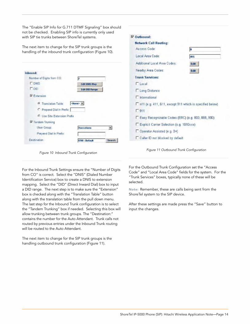
For the Outbound Trunk Configuration set the “Access Code” and “Local Area Code” fields for the system. For the “Trunk Services” boxes, typically none of these will be selected.
Note: Remember, these are calls being sent from the ShoreTel system to the SIP device.
After these settings are made press the “Save” button to input the changes.
The “Enable SIP Info for G.711 DTMF Signaling” box should not be checked. Enabling SIP info is currently only used with SIP tie trunks between ShoreTel systems.
The next item to change for the SIP trunk groups is the handling of the inbound trunk configuration (Figure 10).
For the Inbound Trunk Settings ensure the “Number of Digits from CO” is correct. Select the “DNIS” (Dialed Number Identification Service) box to create a DNIS to extension mapping. Select the “DID” (Direct Inward Dial) box to input a DID range. The next step is to make sure the “Extension” box is checked along with the “Translation Table” button along with the translation table from the pull down menu. The last step for the Inbound Trunk configuration is to select the “Tandem Trunking” box if needed. Selecting this box will allow trunking between trunk groups. The “Destination:” contains the number for the Auto Attendant. Trunk calls not routed by previous entries under the Inbound Trunk routing will be routed to the Auto Attendant.
The next item to change for the SIP trunk groups is the handling outbound trunk configuration (Figure 11).
Figure 10 Inbound Trunk ConfigurationFigure 11 Outbound Trunk Configuration

ShoreTel IP-5000 Phone (SIP): Hitachi Wireless Application Note—Page 15
The next item to change is under “Trunk Digit Manipula-tion” (Figure 12).
Typically when sending digits to the “Hitachi” device it is not needed to check the below three check boxes for “Remove leading 1 from 1+10D”, “Remove leading 1 for Local Area Codes” and “Dial 7 digits for Local Area Code’. Nothing should need done for the “Local Prefixes” drop down.
Selecting the “Edit” button for the Off System Extensions will bring up the”Off System Extension Ranges” dialog box (Figure 13).
Selecting the “New” button will bring up the “New Range” dialog box (Figure 14).
Figure 12 Off System Extension
Input a new range of off system extensions for the SIP devices and click “OK”. For this example the extension range 3000-3019 has been input, which corresponds to the naming convention used in the previous example. This completes the settings needed to set up the SIP Trunk Groups on the ShoreTel system.
Note: It is important to note that only one dynamic trunk group can be set up per ShoreGear switch. If another dynamic trunk group is desired another ShoreGear switch will be needed.
When it is desired to translate an off system extension to a 10 digit DID “Digit Translation must be used. For example, when a call is placed to a Hitachi phone by dialing ext. 3000 but the Hitachi device is configured with 4083313000 then Digit Translation needs to be used. Main reason for doing this is when it’s necessary for calls made from the Hitachi device to present a 10 digit number to the person being called. It can also be needed for 911 reasons (see above section which covers 911 for more information).
Figure 13 Off System Extension Ranges
Figure 14 New Range Settings

ShoreTel IP-5000 Phone (SIP): Hitachi Wireless Application Note—Page 16
ShoreTel System Settings - Individual Trunks
This section covers the configuration of the individual trunks. Select “Administration” then “Trunks” followed by “Indi-vidual Trunks” to configure the individual trunks (Figure 15).
The “Trunks by Group” screen, used to change the individual trunks settings, then appears (Figure 16).
Select the site for the new individual trunk(s) to be added and select the appropriate trunk group from the pull down menu. In this example the site is “Headquarters” and the trunk group is SIP x3020 Intra-site”. Click on the ”Go” button to bring up the “Edit Trunk” screen (Figure 17).
Figure 15 Individual Trunks
From the individual trunks “Edit Trunk” screen, input a name for the individual trunks, select the appropriate switch, select the SIP trunk type and input the number of trunks. When selecting a name, the recommendation is to name the individual trunks the same as the name of the trunk group so that the trunk type and extension range can easily be tracked. Select the switch upon which the individual trunk will be created. For the SIP Trunk Type decide whether the trunks are to be configured as dynamic or static. Dynamic trunks are typically configured for endpoint devices like wireless handsets, conference phone or Integrated Access Devices (IADs). For the “SIP Trunk Type” field select either “Dynamic” or for a static configuration select “Use IP Address” button and input an IP address. In this example a dynamic SIP trunk type has been chosen. The last step is to select the number of individual trunks desired. In the example 20 trunks were chosen, which matches the naming convention used. Once these changes are complete, select the “Save” button to create the list of individual trunks (Figure 18).
Note: Individual SIP trunks cannot span networks. SIP trunks can only terminate on the switch selected. There is no failover to another switch.
After setting up the trunk groups and individual trunks refer to the ShoreTel Product Installation Guide to make the appropriate changes for the User Group settings. This completes the settings for the ShoreTel system side.
Figure 16 Trunks by Group
Figure 17 Edit Trunks Screen for Individual Trunks
Figure 18 Trunks by Group

ShoreTel IP-5000 Phone (SIP): Hitachi Wireless Application Note—Page 17
Hitachi Wireless IP-5000 ConfigurationFor certain portions of the Hitachi Wireless IP-5000 configu-ration it may be necessary to refer to the documentation provided for the Hitachi wireless handset. The document “WirelessIP5000_Administrator_manual.pdf “can be obtained from the “Vendor Overview and Contact” section of this document.
The Hitachi handsets can be configured manually or by using the user.ini (Advanced feature) configuration file (Example in Appendix A). The configuration examples in this document are based on the manual configuration of the Hitachi handsets.
Note: The Hitachi handset can not be configured 100% via the handset. It does require a few configurations which can only be changed through the web interface for the handset or the user.ini file.
Hitachi Handset Connection to WiFi Network
Refer to the documentation to perform the necessary wireless network configuration. Consult with the system administrator, if necessary, to setup the handsets to operate on the wireless network.
Retrieving Handset IP Address
Before connecting to the handsets web interface, obtain the handsets IP Address. Perform the following steps on the Hitachi handset to obtain the IP address:
Press the Menu softkey
Select item #5 - Setup
Select Item #6 - Information
Select item #1 - TCP
Write down the information displayed in the “IP Address” field _____________________________
Push the “END” key on the phone to exit out of the menus.
Connecting to the Handset Web Interface
Access the “web interface” for the Hitachi handset by opening a web browser and entering the IP address (previously obtained) for the handset as follows:
http://<IP address>:8080Example: http://10.0.1.51:8080
1.
2.
3.
4.
5.
6.
Manual Web Interface Configuration
Once the IP address has been input in the web browser a “User ID” and “Password” prompt will be presented. The default “User ID” is “admin” and the default “Password” is “000000” (6 zero’s), the “Wireless IP-5000 Web Configura-tion Tool” screen for the Hitachi handset will appear (Figure 17).
Wireless IP5000 Web Configuration ToolThere are four main sections to address when using the web configuration tool. These sections are:
Configuration
System Setup
Network Setup
Download Configuration File
This documentation will cover items needing configured or validated for use with the ShoreTel system only. For other areas of configuration please consult the Hitachi documen-tation. For example this document will not go over how to configure the WiFi interface to communicate with the network. This document will however tell the user how to configure DTMF tones to work with the ShoreTel system.
Software Version Verification
Confirm the appropriate version of software is used to begin the configuration process by checking the software version detailed under the “Software Specification” heading of the “Wireless IP-5000 Web Configuration Tool” screen (Figure 17).
Verify the version shown is “v2.1.11” or newer. If the firmware is not an appropriate version, see the “Load and Upgrade” option (for firmware update) under the “System Setup” section, consult the Hitachi documentation for further information.
1.
2.
3.
4.
Software Specification
Model WirelessIP5000
Software Version v2.1.11
IP Address 10.9.0.103
Netmask 255.255.255.0
Gateway 10.9.0.1
MAC Address 00:03:2A:00:70:A5
Figure 17 WirelessIP5000 Web Configuration Tool

ShoreTel IP-5000 Phone (SIP): Hitachi Wireless Application Note—Page 18
The Hitachi phone can be configured in three primary way’s.Via the UI on the actual phone (not covered in this document).
Via a web browser interface (as shown in this document) or
Via a “User.ini” file which is uploaded into the phone example config provided in appendix A (details not covered in this document, refer to the Hitachi documenta-tion for more information).
1.
2.
3.
Web Based Configuration
To change the configuration, select the “Configuration” link from the “Main Page” screen.
The “System Configuration” window will appear (Figure 18).
Figure 18 System Configuration

ShoreTel IP-5000 Phone (SIP): Hitachi Wireless Application Note—Page 19
Within the “System Configuration” ShoreTel only docu-ments items that pertain to the ShoreTel system. Consult the Hitachi documentation for configuration of other features in the Hitachi WiFi handset that don’t pertain to the ShoreTel system. Changes need to be made to the follow-ing areas under “System Configuration”, they are: System, RTP RTCP, SIP, Transfer, Conference, DTMF and Tone Type.
System
In the system configuration page for English input the value of “1” (Figure 19). See Hitachi documentation other language value options.
RTP RTCP
Configure the first RTCP value to “off” (Figure 20).
Figure 19 Choosing the language
Figure 20 Turn RTCP off

ShoreTel IP-5000 Phone (SIP): Hitachi Wireless Application Note—Page 20
SIP Configuration
From the SIP page all default values should be fine, just make sure that the local port is set to “5060” as shown in Figure 21.
Figure 21 Confirm “Local Port 5060”

ShoreTel IP-5000 Phone (SIP): Hitachi Wireless Application Note—Page 21
DTMF
DTMF must be set correctly and tested to insure proper DTMF functionality. Without DTMF gaining access to Voice Mail or navigating an Auto Attendant may not work cor-rectly. Confirm the following values are configured. Mode = RFT2833, Duration = 100 ms, RFC 2833 Volume = 10, RFC2833 Payload Type = 102 and Enable Auto DTMF Mode = “ON” (Figure 24).
Tone Type
Another important section that needs configured is the Tone Type. Make sure Dial Tone Type On Idle = CDT, Dial Tone Type on Hold = Silence and Send Dial Tone Type = SDT (Figure 25).
Transfer
In order for “Transfer” to work correctly it’s important all the values are set correctly. Confirm the following is set: Transfer Target hold “On”, Consultation Transfer “Off” and all others should be marked “On” (Figure 22).
Conference
Conference should be set to “off” under “Use Conference” (Figure 23).
Note: From the user.ini file (Appendix A) insure the value “Use_Consultation_Transfer” is set to “0”. Example: Use_Consultation_Transfer=0.
Figure 22 Transfer
Figure 23 Conference
Figure 24 DTMF Values
Figure 25 Tone Type
ShoreTel IP-5000 Phone (SIP): Hitachi Wireless Application Note—Page 22
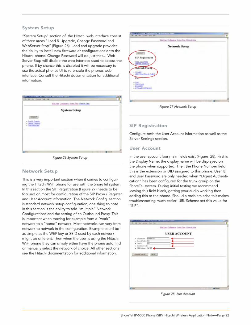
System Setup
“System Setup” section of the Hitachi web interface consist of three areas “Load & Upgrade, Change Password and WebServer Stop” (Figure 26). Load and upgrade provides the ability to install new firmware or configurations onto the Hitachi phone. Change Password will do just that… Web-Server Stop will disable the web interface used to access the phone. If by chance this is disabled it will be necessary to use the actual phones UI to re-enable the phones web interface. Consult the Hitachi documentation for additional information.
Network Setup
This is a very important section when it comes to configur-ing the Hitachi WiFi phone for use with the ShoreTel system. In this section the SIP Registration (Figure 27) needs to be focused on most for configuration of the SIP Proxy / Register and User Account information. The Network Config. section is standard network setup configuration, one thing to note in this section is the ability to add “multiple” Network Configurations and the setting of an Outbound Proxy. This is important when moving for example from a “work” network to a “home” network. Most networks can very from network to network in the configuration. Example could be as simple as the WEP key or SSID used by each network might be different. Then when the user is using the Hitachi WiFi phone they can simply either have the phone auto find or manually select the network of choice. All other sections see the Hitachi documentation for additional information.
Figure 26 System Setup
SIP Registration
Configure both the User Account information as well as the Server Settings section.
User Account
In the user account four main fields exist (Figure 28). First is the Display Name, the display name will be displayed on the phone when supported. Then the Phone Number field, this is the extension or DID assigned to this phone. User ID and User Password are only needed when “Digest Authenti-cation” has been configured for the trunk group on the ShoreTel system. During initial testing we recommend leaving this field blank, getting your audio working then adding this to the phone. Should a problem arise this makes troubleshooting much easier! URL Scheme set this value for “SIP”.
Figure 27 Network Setup
Figure 28 User Account

ShoreTel IP-5000 Phone (SIP): Hitachi Wireless Application Note—Page 23
Server Settings
Server settings section (Figure 29) of the configuration is another important configuration area. From this screen the SIP Proxy, SIP Registrar (optional 2nd) and Registrar Expire are configured. With regards to Domain Realm and Register Retry Backoff Interval settings just leave defaults or refer to the Hitachi documentation.
Settings:
1st Proxy set to IP Address of ShoreGear switch with associated Individual SIP Trunks.1st Registrar set to IP Address of ShoreGear switch with associated Individual SIP Trunks.Register Expire default is 3600. Network Profile
•
•
•
Network Profile
As with many sections of this document this too is an important section as this page controls how the device is able to join a particular network. This document will touch on a couple key areas that need consideration or configura-tion. For information on other sections please refer to the Hitachi documentation.
Configuration sections (Figure 30):
Name: Provide a WiFi network name that is meaningful especially if there will be more then one.
•
Figure 29 Server Settings
SIP Outbound Proxy: This parameter is typically used when the Hitachi is outside the LAN of where the Shore-Gear switch is located with Individual Trunk for SIP. For example… take the Hitachi from the office and go home (or hotel etc… with WiFi), once on that network the Hitachi won’t know how to communicate with the Shore-Gear switch (SIP Proxy and Registrar). If the company has a box such as an “inGate” SIParator (think of this as a LAN to WAN proxy) connected back at the office where the ShoreGear switch is located it will proxy the SIP traffic to the appropriate ShoreGear switch.
Note: inGate (http://www.ingate.com) application note and certification are in progress at the time of this writing.
•
Figure 30 Network Profile

ShoreTel IP-5000 Phone (SIP): Hitachi Wireless Application Note—Page 24
Appendix “A” - User.ini example The below configuration is an example of a user.ini file from a Hitachi WiFi phone running firmware 2.1.11
[SYSTEM]Language=1Admin_Password=TFTP_Server_IP=10.1.3.25Use_DNS_SRV=0Vendor_ID=Vendor_Password=LCD_Contrast=0
[RTP_RTCP]Use_RTCP=0RTP_Port_Min=9000RTP_Port_Max=9020RTCP_Report_Interval=5000RTCP_CNAME=WirelessIP5000Last_RTP_Received_Timeout=0
[WEB_SERVER]Use_WEB_Server=1
[SYSLOG]Mode=0Server_IP=0.0.0.0Server_Port=514Use_MACIP_Header=1
[TIME]Enable_NTP=1Date_Format=0Time_Format=1Time_Zone=-08:00Enable_Daylight_Saving_Time=1DST_Start_Month=3DST_Start_Day=29DST_Start_Hour=2DST_Start_Min=0DST_End_Month=10DST_End_Day=29DST_End_Hour=2DST_End_Min=0NTP_Refresh_Interval=7200NTP_Server1=10.5.0.20NTP_Server2=0.0.0.0
[SIP]Local_Port=5060T1=500T2=4000T4=5000Timer_B=0Timer_F=0Use_User_Agent=0User_Agent_Name=WirelessIP5000Use_Version_On_User_Agent=0Use_Vendor_ID_On_User_Agent=0
Use_MAC_On_User_Agent=0Max_Forwards=70Retry_Hold_On_491=1Caller_ID_Mode=0ICT_Transaction_Max_Count=10Use_rport=0Options_Expire=20Request_REFER_Timeout=200Wait_REFER_Response_Timeout=8000180_Retransmission_Interval=60Invite_Expire=10Reuse_Auth_Header_Within_Dialog=0Register_Contact_Change=0Use_Remove_All_Contact=1Use_Random_Contact=0Retry_To_Redirect_Contact=1
[SDP]Use_Increase_session_id=0Use_Increase_version=1Modified_Session_Detection=0Session_Name=A_converstion[USER_ACCOUNT]Displayname=Pat550UserPhone_Number=550User_ID=550User_Password=URL_Scheme=0
[SERVER_SETTINGS]1st_Proxy=10.1.1.681st_Registrar=10.1.1.682nd_Proxy=2nd_Registrar=Domain_Realm=Register_Expire=3600Register_Retry_Backoff_Interval=6,12,24,48,96
[REDUNDANCY]Mode=0Request_Timeout=4000Use_Fixed_Primary_Server=1Use_DNS_Additional_Records=1
[DIALPLAN]External_Prefix=0Caller_ID_On_Prefix=186Caller_ID_Off_Prefix=184
[BASIC_CALL]Busy_Tone_Count=10Call_Waiting_Tone_Count=1Reject_Hold_Request_On_Hold=0Reject_Hold_Request_On_2Calls=0Block_Request_Hold_On_Holded=0

ShoreTel IP-5000 Phone (SIP): Hitachi Wireless Application Note—Page 25
Session_Expire=90Ringing_Timeout=180Update_RBT=0Dial_Sending_Timeout=30000Check_Alias_In_Call_List=1Remove_DASH_On_Alias=1Use_Silent_Packet_On_Mute=0[HOLD]Mode=0Use_Local_Hold_Tone=1RTP_Hold_Multiframe=40
[MWI]Use_MWI=1Use_Subscribe=1Subscribe_Server=Subscribe_Expire=3600
[TRANSFER]Use_Transfer_Target_Hold=1Use_Consultation_Transfer=0Use_Blind_Transfer=1Use_100_NOTIFY=1Use_Attended_Transfer_On_Incomming_Call=1Use_Contact_For_Refer_To=1Use_Attended_Transfer_On_Call_Switch=1
[CONFERENCE]Use_Conference=0Phone_Number=conference
[DIAL_MODE]DTMF_Input_Timeout=20UnHold_Indication_Timeout=30Overlap_Send_Timeout=4Use_Overlap_Send_on_Hold=0
[RING]Use_Ring=1External1_Ring_Type=11External1_Mode=0External1_Led=1External2_Ring_Type=4External2_Mode=0External2_Led=1Internal1_Ring_Type=12Internal1_Mode=0Internal1_Led=2Internal2_Ring_Type=6Internal2_Mode=0Internal2_Led=2Message_Mode=0Message_Ring_Type=1Message_Ring_Volume=3ID_String_External1=ID_String_External2=ID_String_Internal1=ID_String_Internal2=ID_String_Silence=
[KEY_TONE]Key_Tone_Volume=4
[WIFI]Data_Packet_TxRate=0Dot11_Packet_TxRate=0Use_PowerSave=1PowerSave_Wakeup_Period=28PowerSave_Awake_Interval=400Domain=0Use_Statistics_Window=0Statistics_Window_Update_Interval=10Use_Meru_Extension=1Short_Retry_Limit=7Long_Retry_Limit=7Preamble_Mode=0RTS_Threshold=2347Default_Listen_Interval=3RxLevel_Association_Threshold=-69Use_PowerSave_Monitor=1Use_Supported_Rates_By_AP=0
[WIFI_SCAN]Scan_Count=1Scan_Channel_List=1,2,3,4,5,6,7,8,9,10,11,12,13,14
[ROAMING]Try_RxLevel=-79PreRoaming_Enable_RxLevel=-59Try_Over_TxError_Count=10Try_Over_RxError_Count=10Level_Diff_Higher_Than_Curr_Site=10Use_Refresh_PreRoaming=1Enable_PreRoaming_On_Association=0PreRoaming_Mode=0PreRoaming_Refresh_Interval=0
[NETWORK1]Name=Config1Enable=1Join_Method=0SIP_Outbound_Proxy=10.1.1.68SSID=vCorpWiFiEnable_DHCP=1Address=10.9.0.103Netmask=255.255.255.0Gateway=10.9.0.1DNS1=10.0.0.20DNS2=10.0.0.44Enable_WEP=1WEP_Bits=1Default_WEP_Key=1WEP_Key1=31:35:32:35:38:39:32:35:31:31:35:39:33WEP_Key2=00:00:00:00:00:00:00:00:00:00:00:00:00WEP_Key3=00:00:00:00:00:00:00:00:00:00:00:00:00WEP_Key4=00:00:00:00:00:00:00:00:00:00:00:00:00Authentication_Algorithm=0Post_Authentication_Mode=08021X_Name=8021X_Password=UAM_Use_Manual=0

ShoreTel IP-5000 Phone (SIP): Hitachi Wireless Application Note—Page 26
UAM_Login_URL=UAM_IDTag_Name=UAM_PWTag_Name=UAM_URL=0.0.0.0UAM_ID=UAM_Password=NAT_Traversal_Mode=0Static_NAT_External_IP=0.0.0.0Static_NAT_Start_Port=0STUN_Server=STUN_Port=3478DiffServ_Signal=0DiffServ_Media=0Jitter_Buffer_Size=60Payload_Type=18,0,8Multiframe=2,2,2
[NETWORK2]Name=Config2Enable=0Join_Method=0SIP_Outbound_Proxy=SSID=Enable_DHCP=1Address=0.0.0.0Netmask=255.255.255.0Gateway=0.0.0.0DNS1=0.0.0.0DNS2=0.0.0.0Enable_WEP=0WEP_Bits=0Default_WEP_Key=1WEP_Key1=WEP_Key2=WEP_Key3=WEP_Key4=Authentication_Algorithm=0Post_Authentication_Mode=08021X_Name=8021X_Password=UAM_Use_Manual=0UAM_Login_URL=UAM_IDTag_Name=UAM_PWTag_Name=UAM_URL=0.0.0.0UAM_ID=UAM_Password=NAT_Traversal_Mode=0Static_NAT_External_IP=0.0.0.0Static_NAT_Start_Port=0STUN_Server=STUN_Port=3478DiffServ_Signal=0DiffServ_Media=0Jitter_Buffer_Size=60Payload_Type=0,8,18Multiframe=2,2,2
[NETWORK3]Name=Config3Enable=0
Join_Method=0SIP_Outbound_Proxy=SSID=Enable_DHCP=1Address=0.0.0.0Netmask=255.255.255.0Gateway=0.0.0.0DNS1=0.0.0.0DNS2=0.0.0.0Enable_WEP=0WEP_Bits=0Default_WEP_Key=1WEP_Key1=WEP_Key2=WEP_Key3=WEP_Key4=Authentication_Algorithm=0Post_Authentication_Mode=08021X_Name=8021X_Password=UAM_Use_Manual=0UAM_Login_URL=UAM_IDTag_Name=UAM_PWTag_Name=UAM_URL=0.0.0.0UAM_ID=UAM_Password=NAT_Traversal_Mode=0Static_NAT_External_IP=0.0.0.0Static_NAT_Start_Port=0STUN_Server=STUN_Port=3478DiffServ_Signal=0DiffServ_Media=0Jitter_Buffer_Size=60Payload_Type=0,8,18Multiframe=2,2,2
[NETWORK4]Name=Config4Enable=0Join_Method=0SIP_Outbound_Proxy=SSID=Enable_DHCP=1Address=0.0.0.0Netmask=255.255.255.0Gateway=0.0.0.0DNS1=0.0.0.0DNS2=0.0.0.0Enable_WEP=0WEP_Bits=0Default_WEP_Key=1WEP_Key1=WEP_Key2=WEP_Key3=WEP_Key4=Authentication_Algorithm=0Post_Authentication_Mode=08021X_Name=8021X_Password=

ShoreTel IP-5000 Phone (SIP): Hitachi Wireless Application Note—Page 27
UAM_Use_Manual=0UAM_Login_URL=UAM_IDTag_Name=UAM_PWTag_Name=UAM_URL=0.0.0.0UAM_ID=UAM_Password=NAT_Traversal_Mode=0Static_NAT_External_IP=0.0.0.0Static_NAT_Start_Port=0STUN_Server=STUN_Port=3478DiffServ_Signal=0DiffServ_Media=0Jitter_Buffer_Size=60Payload_Type=0,8,18Multiframe=2,2,2
[NETWORK5]Name=Config5Enable=0Join_Method=0SIP_Outbound_Proxy=SSID=Enable_DHCP=1Address=0.0.0.0Netmask=255.255.255.0Gateway=0.0.0.0DNS1=0.0.0.0DNS2=0.0.0.0Enable_WEP=0WEP_Bits=0Default_WEP_Key=1WEP_Key1=WEP_Key2=WEP_Key3=WEP_Key4=Authentication_Algorithm=0Post_Authentication_Mode=08021X_Name=8021X_Password=UAM_Use_Manual=0UAM_Login_URL=UAM_IDTag_Name=UAM_PWTag_Name=UAM_URL=0.0.0.0UAM_ID=UAM_Password=NAT_Traversal_Mode=0Static_NAT_External_IP=0.0.0.0Static_NAT_Start_Port=0STUN_Server=STUN_Port=3478DiffServ_Signal=0DiffServ_Media=0Jitter_Buffer_Size=60Payload_Type=0,8,18Multiframe=2,2,2
[DTMF]Mode=2Duration=100RFC2833_Volume=10RFC2833_Payload_Type=101Enable_Auto_DTMF_Mode=1
[CALLER_ID]Use_Caller_ID_OnOff=1Enable_Caller_ID=1Anonymous_Displayname=AnonymousUse_Update_Caller_ID=0Hide_Displayname=0Update_Caller_ID_After_Transfer=1
[UI]Dial_Number_Font_Size=1Enable_Key_Lock=0Enable_Key_Lock_Password=1Enable_Mannermode=0Enable_Error_Indication=1Use_Advanced_Rate_Set=0Network_Setup_Menu_Location=1SIP_Menu_Location=1[SMS]Use_SMS=1Message_Server=
[PHONEBOOK]Use_Index_Sending=1[PRESENCE]Use_Presence=1Enable_Online_Ring=1Online_Ring_Type=3Online_Ring_Mode=3Subscribe_Expire=600Presence_Server=
[SERVICE_LAMP]Enable_Service_Lamp=1Red_Alert_Antenna_Level=0Indication_Interval=10Indication_Mode=0 [DYNAMIC_NETWORK]Backoff_Interval=4,8,16,32,64DHCP_Verify_Count=3DHCP_Verify_Interval=38021X_Bind_Timeout=15
[TONE_TYPE]Dial_Tone_Type_On_Idle=2Dial_Tone_Type_On_Hold=0Send_Dial_Tone_Type=1
[AUTO_UPGRADE]Enable=0Time=0Repeat=0

960 Stewart Drive Sunnyvale, CA 94085 USA Phone +1.408.331.3300 +1.877.80SHORE Fax +1.408.331.3333 www.shoretel.com Copyright © 2007 ShoreTel. All rights reserved. ShoreTel, the ShoreTel Logo, ShoreCare, ShoreGear, ShoreWare, ShorePhone, ControlPoint and Office Anywhere are trademarks or registered trademarks of ShoreTel, Inc.
All other marks are the property of their respective owners. Specifications are subject to change without notice. ST-132_2.07
Record of Change
This application note is subject to change. Updates and corrections are always welcome. Please submit any updates or corrections to [email protected].
Issue Author Reason for Change Date
2.0 J. Casselman Edit February 5, 2007
1.0 J. Casselman Initial Release May 24, 2006