high resolution undersea acoustic data acquisition using
TRANSCRIPT

HIGH RESOLUTION UNDERSEA ACOUSTIC DATA ACQUISITIONUSING SINGLE-BOARD MICROCONTROLLERS
Ben Travaglione1,2, Andrew Munyard1, and David Matthews1
1Defence Science and Technology Group, Australia2Email: [email protected]
Abstract
There are a number of situations in the undersea environment in which it would be useful to have alow-cost, low-power, deployable, high resolution acoustic data acquisition system. Thanks to the rapidtechnological advances within the mobile computing industry, there are now a number of small, low-cost, single-board microcontrollers available that lend themselves to the tasks of data acquisition andprocessing. In this paper, we show how a single-board microcontroller, along with a 24-bit analogue-to-digital converter chip, and some amplification and filtering circuitry can be combined with a PVDFhydrophone to record and analyse high resolution acoustic data. We compare the performance of thislow-cost acoustic data acquisition system with a commercial alternative.
1. Introduction
Over recent years there has been a flourishing of low-cost, configurable single-board microcontrollers. Ina previous work[1] we compared the performance of a number of these devices with regard to underseaacoustic data acquisition. The highest precision that we investigated was 12 bits, and this was recordingonly a single channel. In this work we couple a Beaglebone Black to an ADS1271 to obtain two channelrecordings at 24 bit precision and 130208 samples per second.
In Section 2 we describe the Beaglebone Black in some detail, concentrating on the programmablereal-time units (PRUs) in Section 2.1. Then, in Section 3, we introduce the ADS1271 which is a delta-sigma, 24-bit analog-to-digital converter. We discuss how the PRUs can be used to allow the BeagleboneBlack to control the ADS1271 chips, and also highlight the need for over-voltage protection circuits.Having explained how a Beaglebone Black and an ADS1271 can be coupled to produce a low-cost,configurable, high-speed, high-precision, real-time data acquisition system, in Section 4 we compare thissystem’s performance to a commercial alternative. In Section 5 we briefly show how this data acquisitionsystem can be combined with some PVDF hydrophones and some charge amplification circuitry toproduce a complete undersea acoustic data acquisition system. We discuss the on-board signal processingcapabilities of the Beaglebone Black in Section 6. Finally, we draw some conclusions and point to somefurther research regarding microcontrollers in at-sea deployable systems.
1
2. Beaglebone Black
The Beaglebone Black (BBB) is a single-board microcontroller/computer produced by Texas Instruments[2,3]. It currently retails at around AU$ 70. The Beaglebone Black is open-source hardware, designed to runopen-source software. With a physical footprint not much larger than a credit card, and drawing less than2 Watts, it has 512 Mb of RAM, 4 Gb of onboard memory (which can be expanded by using the attachedmicroSD slot), and a plethora of interface options including USB, Ethernet, HDMI, SPI, I2C, UARTand a large number of GPIO pins. There are a range of choices for the open-source operating system onthe Beaglebone Black. For this paper, we used the currently recommended choice of Linux Debian[4].Most of the features of the Beaglebone Black are contained within a single chip: the AM335x Sitara[5]. The main processor on the AM335x Sitara runs at 1 GHz. The small size, low cost and configurablenature of the Beaglebone Black mean that the device is well suited as the basis for the creation of smartacquisition systems[6, 7]. However, the component which sets the Beaglebone Black apart from othersingle-board microcontrollers currently on the market is a subsystem of the AM335x Sitara known as theprogrammable real-time units (PRUs).
2.1 Programmable real-time units
The PRUs are two independent processors contained within the AM335x Sitara chip on the BeagleboneBlack [8, 9]. Each of these processors are 32-bit, running at 200 MHz and are independent of the mainprocessor. They each have 8 KB of programmable memory and direct access to general inputs and outputs.These processors are able to exchange information with the main processor and each other through theuse of shared RAM and a number of interrupts.
The PRUs allow for the development of applications on the Beaglebone Black which requirereal-time processing. Unfortunately the manufacturer does not provide direct support for developerswishing to utilise the PRUs in the development of applications requiring real-time processing. Instead, themanufacturer has provided an open-source package of code called the AM335x PRU Package[10], and aonline community support website[11]. Programs for the PRUs need to be written in assembly language.As well as some documentation, the PRU package contains an assembler program, which translates theassembly language program into binary code which is executable on the PRUs and it also contains a Linuxdriver which allows the main processor to control the PRUs.
The PRUs can get direct access to external sensors through the GPIO pins on the Beaglebone Black,however configuring these pins is rather complicated, and not all pins are accessible to the PRUs in allconfigurations. For example, both the 4 Gb storage and the HDMI port on the Beaglebone Black useGPIO pins which are shared with the PRUs, meaning that these devices need to be disabled in order toaccess all the GPIOs of the PRUs.
3. ADS1271
The AM335x Sitara chip on the Beaglebone Black includes an analog-to-digital converter (ADC) howeverthis internal ADC has only 12 bits of precision, and even though it is possible to convert from eightdifferent channels, this is done sequentially, limiting the device to effectively one 12-bit channel if youwish to run at the maximum sample rate. Often, 12 bits of precision will be insufficient for underseaacoustic recordings. We therefore turn to an external ADC for greater precision. We chose to use theADS1271, which is a 24-bit, delta-sigma ADC[12, 13]. It has been designed for data rates up to 105kSPS(although in our testing we managed to successfully record at a rate of 130kSPS). This device has anumber of features which make it attractive for use in an undersea acoustic acquisition system includinglow drift and low in-band noise. For easy of utilisation, it is possible to acquire two of these chips ona evaluation board (ADS1271 Evaluation Module [14]), which assists greatly in interfacing with theBeaglebone Black.
The ADS1271 chips are able to communicate with external microcontrollers using either an SPI ora frame-sync serial interface. Given the 200 MHz clock speed limitation of the PRUs, we found it easier
2

Figure 1: Simple circuit to protect the ADS1271 chips from damage due to excessive input voltage.
to link the ADS1271 and the Beaglebone Black using the frame-sync interface as discussed in Section 3.2.The ADS1271 has three different operating modes, in turn optimising for speed, resolution or power. Forour requirements, we ran the chips in the mode which allows for the greatest sample rate.
3.1 Over-voltage protection
The ADS1271 requires an external reference voltage. For the recordings contained in this paper weused the 2.5 V reference voltage provided by the ADS1271 Evaluation Module. Thus, according to thedata-sheet for the ADS1271 [13], the input signals must be kept between −2.8 V and 2.8 V. We used thesimple diode protection circuit depicted in Figure 1 to keep the input voltages well within these limits.
3.2 Connecting the Beaglebone Black and the ADS1271
In this section we give a brief overview of the technique we used to interface the ADS1271 to theBeaglebone Black using the PRUs in order to create a low-cost, configurable, high-speed, high-precision,real-time data acquisition system.
We utilised both PRUs in the process of interfacing with the two ADS1271 chips contained on theADS1271 Evaluation Module. One of the PRUs is used to produce two synchronised clocks, which areboth fed into the two ADS1271 chips; one clock acts as the master clock for the ADC and another, slowerclock is used in the frame-sync serial communications protocol. The second PRU also receives the twoclocks from the first PRU and additionally it receives the digital output from the two ADS1271 chips.
The sample rate of the system is determined by the clock rate of the PRUs. As previously mentioned,the PRUs run at 200 MHz. This means that each clock cycle takes 5 ns. It takes six PRU clock cyclesto complete one ADC clock cycle. This is because, for each clock cycle, we need to set the FSYNCoutput pin, the ADC clock output pin and the serial clock output pin, taking three cycles. We need thedown-cycle to be equal to the up-cycle for the ADC clock, so we need a further three cycles for clearingthe various pins. When the ADS1271 is running in fast frame-sync mode, there needs to be 4 ADC cyclesfor every serial clock cycle, and 64 serial clock cycles between each new ADC output. This means thatthe total time to acquire a sample from each ADS1271 ADC is 5× 6× 4× 64 = 7680 nanoseconds, whichgives a sample rate of approximately 130208 samples per second.
The second PRU is able to store the 24-bit samples from the two ADCs in a buffer, which by defaultis only 256 Kb, but is reconfigurable to a maximum size of 8 Mb. The second PRU actually uses twobuffers; when one buffer fills, it begins using the second buffer, whilst also signalling the BeagleboneBlack primary processor to copy the full buffer across to file storage. This memory copy is infrequentenough that under normal load conditions the primary processor is able to consistently complete the taskwithout any dropped packets.
4. Data acquisition system performance
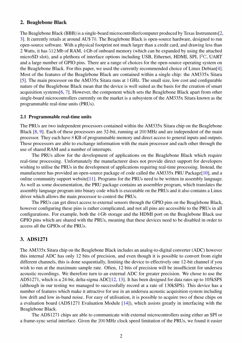
We tested the BBB/ADS1271 system with a variety of different input signals, and compared the output tothe output recorded on a Bruel and Kjær Type 3050-B-060 [15]. The frequency response for two sinusoidalinputs are depicted in Figure 2 and Figure 3. These show the responses of both the BBB/ADS1271 and
3

0 10 20 30 40 50 60Frequency (kHz)
-200.0
-150.0
-100.0
-50.0
0.0
dBV
Bruel and Kjær Type 3050-B-060-200.0
-150.0
-100.0
-50.0
0.0
dBV
Frequency response for a 10kHz sinusoidal signal
BBB with ADS1271
Figure 2: Frequency response to a 10kHz sinusoidal signal of the BBB/ADS1271 (Red) and the Brueland Kjær Type 3050-B-060 (Blue).
the Bruel and Kjær Type 3050-B-060 to sinusoidal signals at 10 kHz and 42 kHz respectively. Thesesignals were generated using an Agilent 33220A[16] signal generator.
It is evident from Figure 2 and Figure 3 that the noise-floor and signal level of the BBB/ADS1271acquisition system is comparable to that of the Bruel and Kjær Type 3050-B-060. Both devices also havea comparable maximum sample rate.
5. Underwater acoustic data acquisition
In linking a Beaglebone Black to an ADS1271 Evaluation Module as described in Section 3.2 we now havea two-channel, low-cost, configurable, deployable, high-speed, high-precision data acquisition system. Inthis section we describe how we utilised this acquisition system to compare the performance of a PVDFhydrophone with a HTI-96-MIN hydrophone[17]. For details of using PVDF film as a hydrophone see[18], [19] and references therein.
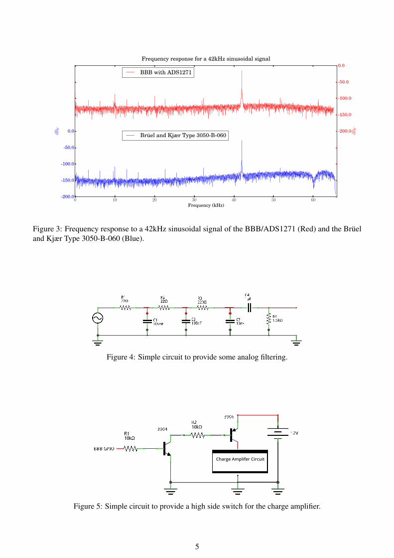
The HTI hydrophone comes with an internal pre-amplifier, so it is able to be directly connected tothe analog input of the ADS1271 (utilising the over-voltage protection circuit described in Section 3.1).The PVDF hydrophones that we were testing required some amplification and filtering before connectingto the ADS1271. We used a Reson CCA1000 Conditioning Charge Amplifier[20] as the amplifier, and asimple passive RC band-pass filter, depicted in Figure 4.
The charge amplifier runs on 12V DC at approximately 50 mA, which is about a third of the powerneeded to run the Beaglebone Black. The amplifier is only required when the unit is recording, and so itmakes sense to use the Beaglebone Black to power up the amplifier only when required. Unfortunatelythe charge amplifier uses a ground which is common with the negative of the input and output signal. Thismeans that a single transistor can not be used as a low-side switch, instead we use one of the GPIO pinson the Beaglebone Black, and a simple high-side switching circuit depicted in Figure 5.
5.1 Measurements in a tank
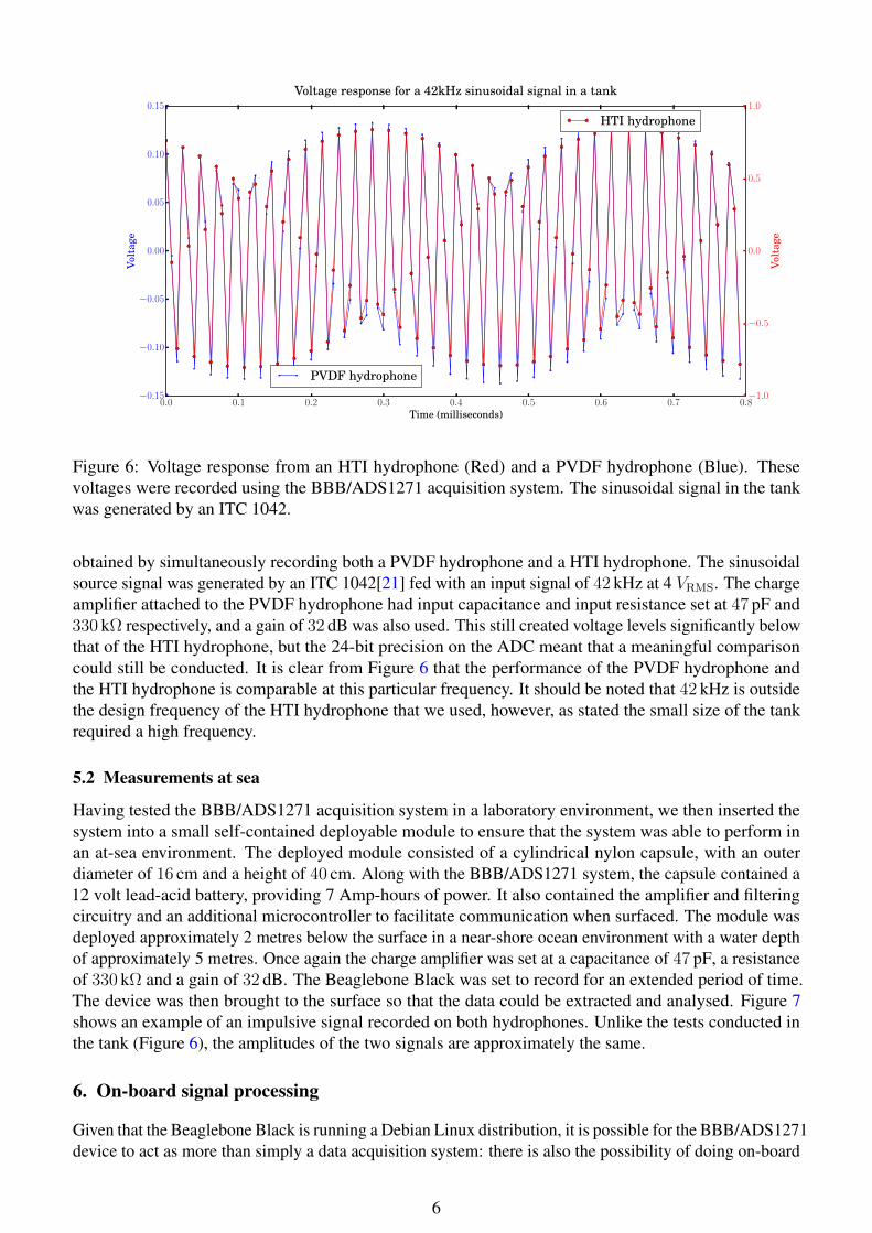
Our first series of tests were conducted in a cylindrical freshwater tank (the tank has a depth of 1.0 metresand a diameter of 1.8 metres). Given the relatively small size of the tank, it was necessary to conduct thetests at high frequencies to minimize the effects of reverberation. Figure 6 shows an example of the results
4
0 10 20 30 40 50 60Frequency (kHz)
-200.0
-150.0
-100.0
-50.0
0.0
dBV
Bruel and Kjær Type 3050-B-060-200.0
-150.0
-100.0
-50.0
0.0
dBV
Frequency response for a 42kHz sinusoidal signal
BBB with ADS1271
Figure 3: Frequency response to a 42kHz sinusoidal signal of the BBB/ADS1271 (Red) and the Brueland Kjær Type 3050-B-060 (Blue).
Figure 4: Simple circuit to provide some analog filtering.
Figure 5: Simple circuit to provide a high side switch for the charge amplifier.
5
0.0 0.1 0.2 0.3 0.4 0.5 0.6 0.7 0.8Time (milliseconds)
−0.15
−0.10
−0.05
0.00
0.05
0.10
0.15
Vol
tage
PVDF hydrophone−1.0
−0.5
0.0
0.5
1.0
Vol
tage
Voltage response for a 42kHz sinusoidal signal in a tank
HTI hydrophone
Figure 6: Voltage response from an HTI hydrophone (Red) and a PVDF hydrophone (Blue). Thesevoltages were recorded using the BBB/ADS1271 acquisition system. The sinusoidal signal in the tankwas generated by an ITC 1042.
obtained by simultaneously recording both a PVDF hydrophone and a HTI hydrophone. The sinusoidalsource signal was generated by an ITC 1042[21] fed with an input signal of 42 kHz at 4 VRMS. The chargeamplifier attached to the PVDF hydrophone had input capacitance and input resistance set at 47 pF and330 kΩ respectively, and a gain of 32 dB was also used. This still created voltage levels significantly belowthat of the HTI hydrophone, but the 24-bit precision on the ADC meant that a meaningful comparisoncould still be conducted. It is clear from Figure 6 that the performance of the PVDF hydrophone andthe HTI hydrophone is comparable at this particular frequency. It should be noted that 42 kHz is outsidethe design frequency of the HTI hydrophone that we used, however, as stated the small size of the tankrequired a high frequency.
5.2 Measurements at sea
Having tested the BBB/ADS1271 acquisition system in a laboratory environment, we then inserted thesystem into a small self-contained deployable module to ensure that the system was able to perform inan at-sea environment. The deployed module consisted of a cylindrical nylon capsule, with an outerdiameter of 16 cm and a height of 40 cm. Along with the BBB/ADS1271 system, the capsule contained a12 volt lead-acid battery, providing 7 Amp-hours of power. It also contained the amplifier and filteringcircuitry and an additional microcontroller to facilitate communication when surfaced. The module wasdeployed approximately 2 metres below the surface in a near-shore ocean environment with a water depthof approximately 5 metres. Once again the charge amplifier was set at a capacitance of 47 pF, a resistanceof 330 kΩ and a gain of 32 dB. The Beaglebone Black was set to record for an extended period of time.The device was then brought to the surface so that the data could be extracted and analysed. Figure 7shows an example of an impulsive signal recorded on both hydrophones. Unlike the tests conducted inthe tank (Figure 6), the amplitudes of the two signals are approximately the same.
6. On-board signal processing
Given that the Beaglebone Black is running a Debian Linux distribution, it is possible for the BBB/ADS1271device to act as more than simply a data acquisition system: there is also the possibility of doing on-board
6

0 1 2 3 4 5Time (milliseconds)
−0.5
0.0
0.5
1.0
1.5
Vol
tage
PVDF hydrophone
−1.5
−1.0
−0.5
0.0
0.5
Vol
tage
Voltage response for an impulsive signal at sea
HTI hydrophone
Figure 7: Voltage response from an HTI hydrophone (Red) and a PVDF hydrophone (Blue) recordedusing the BBB/ADS1271 acquisition contained in a small deployable self-contained module.
processing. Development of on-board processing becomes relatively straight forward with the use ofSciPy[22]. SciPy is a Python-based ecosystem of open-source software for mathematics, science, andengineering. The packages bundled in SciPy include many signal processing algorithms, FFTs and awide variety of filtering and spectral analysis algorithms. Python also comes with a variety of useful testand evaluation modules for testing the performance of your code and the microcontroller itself. In manyinstances, the Beaglebone Black can simultaneously do signal processing on the data which are beingacquired using the PRUs, however, if the processing load is too high for a single Beaglebone Black it canpass the data over to an auxiliary microcontroller for signal processing, using an Ethernet connection.
7. Conclusions and further research
In this paper we have shown that by utilising the programmable real-time units on a Beaglebone Black itis possible to use an ADC chip to produce a low-cost, configurable, high-speed, high-precision, real-timedata acquisition system. Using a single Beaglebone Black and a ADS1271 Evaluation Module we wereable to reliably record two channels of 24-bit data at a rate of 130208 samples per second. We showed thatthe recording speed, precision and noise-floor of this acquisition system is comparable to a more expensivecommercial alternative. As an example of the uses of this acquisition system, we compared the output oftwo different types of hydrophone. We also highlighted the on-board signal processing potential of theBeaglebone Black, which is made readily available through the use of open-source scientific computingtools such as SciPy.
Future avenues of research that we intend to pursue include testing the capacity of the BeagleboneBlack to do concurrent signal processing while gathering data and expanding the number of input channels.We also intend to conduct more at-sea trials to test the durability and reliability of the system.
References
[1] B. Travaglione, A. Munyard, and D. Matthews, “Using low cost single-board microcontrollers to recordunderwater acoustical data,” in 43rd International Congress on Noise Control Engineering, 2014.
[2] “Beagleboard black homepage.” http://beagleboard.org/black. Accessed: 2015-09-30.
7

[3] D. Molloy, Exploring BeagleBone : Tools and Techniques for Building with Embedded Linux. Wiley, 2015.
[4] “Debian: Free, open-source operating system.” http://www.debian.org. Accessed: 2015-09-30.
[5] Texas Instruments, “AM3358 Sitara Processor.” http://www.ti.com/product/am3358. http://www.ti.com/product/am3358.
[6] T. Araari, L. Charaabi, and K. Jelassi, “Design and implementation of an embedded data acquisition basedon linux system for smart grid,” in Electrical Sciences and Technologies in Maghreb (CISTEM), 2014International Conference on, pp. 1–5, Nov 2014.
[7] A. Chianese, F. Piccialli, and G. Riccio, Designing a smart multisensor framework based on beagleboneblack board., vol. 330 of Lecture Notes in Electrical Engineering. Department of Electrical Engineering andInformation Technologies, University of NaplesFederico II: Springer Verlag, 2015.
[8] Texas Instruments, AM335x Sitara Processors (Rev H), May 2015. http://www.ti.com/lit/ds/symlink/am3359.pdf.
[9] Texas Instruments, AM335x Sitara Processors Technical Reference Manual (Rev L), February 2015. http://www.ti.com/lit/ug/spruh73l/spruh73l.pdf.
[10] “Drivers and example code for PRUs,” April 2015. https://github.com/beagleboard/am335x_pru_package.
[11] “TI AM33XX PRUSSv2 Support Site.” http://elinux.org/Ti_AM33XX_PRUSSv2. Accessed 2015-09-30.
[12] Texas Instruments, “ADS1271 24-Bit, 105kSPS Industrial Delta-Sigma ADC.” http://www.ti.com/product/ads1271. http://www.ti.com/product/ads1271.
[13] Texas Instruments, ADS1271 24-Bit, 105kSPS Industrial Delta-Sigma ADC datasheet, October 2007. http://www.ti.com/lit/ds/symlink/ads1271.pdf.
[14] Texas Instruments, ADS1271EVM and ADS1271EVM-PDK User’s Guide, November 2014. http://www.ti.com/lit/ug/sbau107c/sbau107c.pdf.
[15] Bruel and Kjær, “Type 3050-b-060 multi-purpose 6-channel input module.” http://www.bksv.com/products/frontends/lanxi/modules/type-3050. Accessed: 2014–7-31.
[16] “Agilent 33220A arbitrary waveform generator.” http://www.home.agilent.com/en/pd-127539-pn-33220A/function-arbitrary-waveform-generator-20-mhz?&cc=AU&lc=eng. Accessed: 2015-09-30.
[17] “HTI-96-MIN hydrophone.” http://www.hightechincusa.com/96_MIN.html.
[18] D. Killeen, M. Legg, and D. Matthews, “A prototype pvdf underwater pressure-gradient acoustic intensityprobe,” Proceedings of Acoustics, vol. 4014, p. 5, 2009.
[19] D. Matthews, A. Munyard, and D. Killeen, “The effect of polyurethane encapsulant on the response of pvdfhydro-phones in the frequency range from 30 khz to 100 khz,” Proceedings of Acoustics, 2013.
[20] “Reson CCA1000 conditioning charge amplifer.” http://www.teledyne-reson.com/products/hydrophones/accessories/ec6067/.
[21] “ITC-1042 spherical omnidirectional transducer.” http://www.channeltechgroup.com/publication/model-itc-1042-spherical-omnidirectional-transducer/.
[22] E. Jones, T. Oliphant, P. Peterson, et al., “SciPy: Open source scientific tools for Python.” http://www.scipy.org/,2001–. [Online; accessed 2015-08-07].
8