high-frequency and high-voltage asymmetric bipolar pulse
TRANSCRIPT
electronics
Article
High-Frequency and High-Voltage Asymmetric BipolarPulse Generator for Electroporation Based Technologiesand Therapies
Eva Pirc 1 , Damijan Miklavcic 1 , Katja Uršic 2 , Gregor Serša 2,3 and Matej Reberšek 1,*
Citation: Pirc, E.; Miklavcic, D.;
Uršic, K.; Serša, G.; Reberšek, M.
High-Frequency and High-Voltage
Asymmetric Bipolar Pulse Generator
for Electroporation Based
Technologies and Therapies.
Electronics 2021, 10, 1203. https://
doi.org/10.3390/electronics10101203
Academic Editor: Yahya M. Meziani
Received: 17 April 2021
Accepted: 13 May 2021
Published: 18 May 2021
Publisher’s Note: MDPI stays neutral
with regard to jurisdictional claims in
published maps and institutional affil-
iations.
Copyright: © 2021 by the authors.
Licensee MDPI, Basel, Switzerland.
This article is an open access article
distributed under the terms and
conditions of the Creative Commons
Attribution (CC BY) license (https://
creativecommons.org/licenses/by/
4.0/).
1 Faculty of Electrical Engineering, University of Ljubljana, Tržaška 25, 1000 Ljubljana, Slovenia;[email protected] (E.P.); [email protected] (D.M.)
2 Department of Experimental Oncology, Institute of Oncology Ljubljana, Zaloška 2, 1000 Ljubljana, Slovenia;[email protected] (K.U.); [email protected] (G.S.)
3 Faculty of Health Sciences, University of Ljubljana, Zdravstvena Pot 5, 1000 Ljubljana, Slovenia* Correspondence: [email protected]
Abstract: Currently, in high-frequency electroporation, much progress has been made but limited toresearch groups with custom-made laboratory prototype electroporators. According to the reviewof electroporators and economic evaluations, there is still an area of pulse parameters that needsto be investigated. The development of an asymmetric bipolar pulse generator with a maximumvoltage of 4 kV and minimum duration time of a few hundred nanoseconds, would enable in vivoevaluation of biological effects of high-frequency electroporation pulses. Herein, from a series of mostcommonly used drivers and optical isolations in high-voltage pulse generators the one with optimalcharacteristics was used. In addition, the circuit topology of the developed device is described indetail. The developed device is able to generate 4 kV pulses, with theoretical 131 A maximal currentand 200 ns minimal pulse duration, the maximal pulse repetition rate is 2 MHz and the burst maximalrepetition rate is 1 MHz. The device was tested in vivo. The effectiveness of electrochemotherapyof high-frequency electroporation pulses is compared to “classical” electrochemotherapy pulses.In vivo electrochemotherapy with high-frequency electroporation pulses was at least as effectiveas with “classical” well-established electric pulses, resulting in 86% and 50% complete responses,respectively. In contrast to previous reports, however, muscle contractions were comparable betweenthe two protocols.
Keywords: electroporation; electroporation device; high-frequency; bipolar; asymmetric; SiC MOS-FET; high-voltage; pulse generator; electrochemotherapy
1. Introduction
In electroporation due to the exposure of cells to high-voltage electric pulse, the cellmembrane becomes permeable to molecules that otherwise cannot cross the cell mem-brane [1]. In reversible electroporation the cell recovers after the electric pulse application.In contrast, in irreversible electroporation (IRE) the cell dies due to excessive damage [2].Electroporation is already well established in medicine and food processing [3,4]. The tech-nology holds promises also in other fields, such as biomass production [5] and biotechnol-ogy [6]. However, different pulses are used in different electroporation-based applicationsi.e., pulse amplitude, pulse width, a number of pulses or bursts, and pulse or burst repeti-tion rate [7–9]. In most applications, optimization of parameters still needs to be performed.Therefore, specific pulse generators, i.e., electroporators have to be designed for specificapplications [10,11]. Additionally, electrical properties of biological loads vary considerablyand due to electroporation their conductivity changes during the pulse application [12–17].
Electroporation is well established in cancer treatment, i.e., electrochemotherapy(ECT) and IRE. ECT is a local antitumor therapy, in which electroporation facilitates
Electronics 2021, 10, 1203. https://doi.org/10.3390/electronics10101203 https://www.mdpi.com/journal/electronics
Electronics 2021, 10, 1203 2 of 19
chemotherapeutic drug entry into cells [18,19]. According to the standard operatingprocedure, intratumoral or intravenous delivery of the chemotherapeutic drug bleomycin(BLM) or cisplatin (CDDP) is followed, by the application of eight high-voltage pulses,which are monopolar, 100 µs long, with a pulse repetition rate 1 Hz or 5 kHz and voltage todistance ratio between 1000 or 1300 V/cm (depending on the electrode type) [20–22]. IREis clinically used as non-thermal ablation of normal and tumor tissue, in which cells diedue to excessive damage during membrane permeabilization [23–26]. However, IRE doesnot cause the denaturation of proteins, scarring, and damage of blood vessels. Therefore,it has the potential to treat tumors near large blood vessels. In addition, the activation ofthe immune system was observed as in ECT [27–29]. However, an increase in temperaturearound the electrodes can be significant at higher amplitudes and a high number of pulsesdelivered to a limited volume of tissue [30]. Furthermore, nerve stimulation, musclecontractions, and pain are associated with high-voltage pulse delivery [19,25,31]. Theseare also observed in ECT and require additional patient management in terms of musclerelaxant administration prior to treatment [32,33]. Synchronisation of pulse delivery withECG, is required when treatment is performed close to the heart, which renders thetreatment procedure more complex [32,34]. Recently, it was suggested that by applyinghigh-frequency bursts of bipolar pulses, named H-FIRE (High-Frequency IRreversibleElectroporation), muscle contractions can be reduced without compromising the non-thermal mechanism of cell death [35,36]. They also suggest that electric field distributionin tissue is more homogeneous [35]. It was shown in vitro that the transmembrane transferof molecules may be achieved with the same type of pulses [37]. However, H-FIREpulses require higher amplitudes for cell disruption in comparison to longer monopolarpulses [37].
Recently, we demonstrated in vitro that high-frequency electroporation (HF-EP) canbe used for ECT and that higher pulsed electric field, i.e., equal to 3 kV/cm in HF-EP thanin “classical” ECT has to be used in order to obtain comparable effectiveness [38].
With the potential advantages of IRE over current ablation modalities, the technol-ogy seems uniquely suited also for cardiac ablation in the treatment of atrial fibrillation(AF) [24,39–41]. A term “Pulsed field ablation” (PFA) is defined as IRE that uses a burstof bipolar pulses of high-voltage and short duration to create a tissue injury withoutsignificant heating and injury to other tissues [42].
The electric field threshold for muscle contraction is two times lower than the thresholdfor electroporation (for 100 µs long pulses) [43]. The advantage of these specific high-frequency electroporation pulse characteristics might be in reducing muscle contractionand pain sensation during high-voltage pulse delivery [35,36,43]. Recently, a phenomenaof electrical cell sensitization [44,45] and cancellation in the range of microsecond and sub-microsecond pulse duration were reported in vitro [46,47]. These effects i.e., sensitization,cancellation, nerve and muscle decreased excitation effects of the electroporation are still notwell understood and further studies are needed, particularly in vivo, due to inconclusiveresults obtained in vitro [48,49]. Additionally, the use of asymmetric, HF-EP for HF-IREthat could enhance its effectiveness was suggested [50]. Therefore, the development of anasymmetric bipolar electroporator, with a variable setting of pulse duration and voltageamplitude for each half period of the pulse, that can be used in vivo enables a new insightand investigations of cancellation and sensitization relevance in vivo.
For generating electric pulses of up to several kV high-voltage amplitudes threedifferent circuit concepts are used: generator with serial switches [51], Marx generator [52],and a modular pulse generator [53]. For the generation of asymmetric bipolar pulses,an asymmetric H-bridge generator is used where each half of the bridge is powered byits own power supply [54]. For the generation of high-voltage asymmetric bipolar pulses,a serial asymmetric H-bridge generator is, therefore, the simplest and economically mostreasonable solution.
Until now, all H-FIRE studies used custom-made laboratory prototype electroporatorsbased on an H-bridge. Therefore, the research is limited to a few research groups that have
Electronics 2021, 10, 1203 3 of 19
the knowledge and experience to design such custom devices. In addition, pulse deliverysystems are most often only briefly mentioned and not described in detail in the literature.
In conclusion, according to the electroporators review, [10,55], published economicevaluations of ECT and IRE [56–58] and increase of interest in electroporation with bipolarpulses [38,59,60], there is still an area of pulse parameters that needs to be investigated.Here, we present the development of a serial asymmetric H-bridge generator that generatesasymmetric bipolar pulses with a maximum voltage of 4 kV and a minimum duration timeof a few hundred nanoseconds with the emphasis on the importance and the process ofelectronic component selection, and the concept and topology of developed electroporator.In addition, the in vivo evaluation of the developed device is presented, focusing on thefirst in vivo high-frequency electrochemotherapy (HF-ECT).
2. Methods and Materials2.1. Prototype Device
A prototype device that generates high-frequency and high-voltage asymmetric bipo-lar pulses was developed from a prototype serial asymmetric H-bridge generator, digital de-lay generator DG645 (Stanford Research Systems, Sunnyvale, CA, USA), two high-voltagecapacitor banks and two high-voltage power supplies HCP 350-6500 (FuG ElektronikGmbH, Schechen, Germany).
2.1.1. Serial Asymmetric H-Bridge Generator
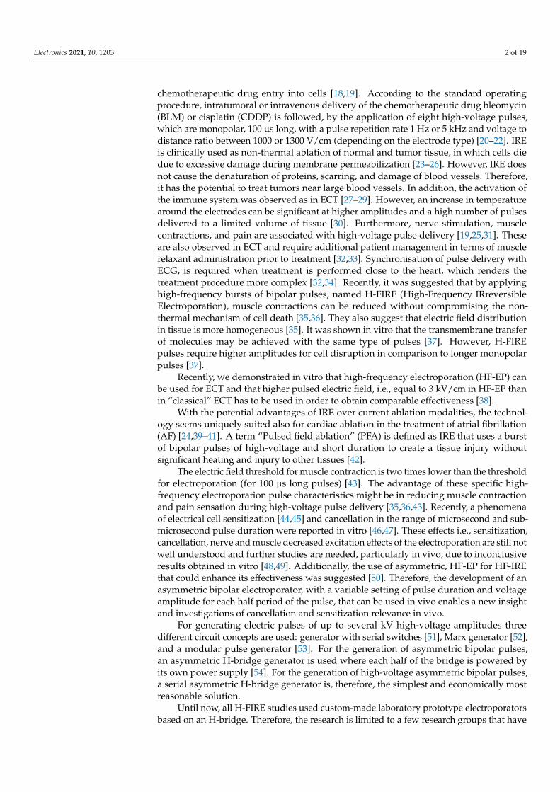
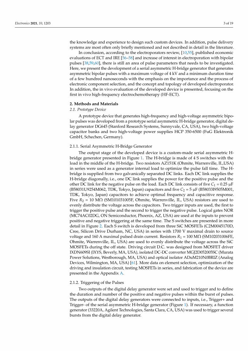
The output stage of the developed device is a custom-made serial asymmetric H-bridge generator presented in Figure 1. The H-bridge is made of 4 S switches with theload in the middle of the H-bridge. Two resistors AZ151K (Ohmite, Warrenville, IL,USA)in series were used as a generator internal load to optimize the pulse fall time. The H-bridge is supplied from two galvanically separated DC links. Each DC link supplies theH-bridge diagonally, i.e., one DC link supplies the power for the positive pulse and theother DC link for the negative pulse on the load. Each DC link consists of five C1 = 0.25 µF(B58031U9254M062, TDK, Tokyo, Japan) capacitors and five C2 = 5 µF (B58033I9505M001,TDK, Tokyo, Japan) capacitors to achieve optimal frequency and capacitive response.Five R2 = 10 MΩ (SM101031005F, Ohmite, Warrenville, IL, USA) resistors are used toevenly distribute the voltage across the capacitors. Two trigger inputs are used, the first totrigger the positive pulse and the second to trigger the negative pulse. Logical gates NOR(MC74AC02DG, ON Semiconductor, Phoenix, AZ, USA) are used at the inputs to preventpositive and negative triggering at the same time. The S switches are presented in moredetail in Figure 2. Each S switch is developed from three SiC MOSFETs (C2M0045170D,Cree, Silicon Drive Durham, NC, USA) in series with 1700 V maximal drain to sourcevoltage and 160 A maximal pulsed drain current. Resistors R1 = 100 MΩ (SM102031006FE,Ohmite, Warrenville, IL, USA) are used to evenly distribute the voltage across the SiCMOSFETs during the off state. Driving circuit D.C. was designed from MOSFET driverIXDN609SI (IXYS, Beverly, MA, USA), isolated DC-DC converter MGJ2D052005SC (MurataPower Solutions, Westborough, MA, USA) and optical isolator ADuM210N0BRIZ (AnalogDevices, Wilmington, MA, USA) [61]. More data on element selection, optimization of thedriving and insulation circuit, testing MOSFETs in series, and fabrication of the device arepresented in the Appendix A.
2.1.2. Triggering of the Pulses
Two outputs of the digital delay generator were set and used to trigger and to definethe duration and number of the positive and negative pulses within the burst of pulses.The outputs of the digital delay generators were connected to inputs, i.e., Trigger+ andTrigger- of the serial asymmetric H-bridge generator (Figure 1). If necessary, a functiongenerator (33220A, Agilent Technologies, Santa Clara, CA, USA) was used to trigger severalbursts from the digital delay generator.
Electronics 2021, 10, 1203 4 of 19
Figure 1. Topology of the serial asymmetric H-bridge generator. Each block marked with S representsone switch presented in Figure 2 marked with a striped line. Logical gates NOR at the input ensureonly one trigger pulse at a time. To generate asymmetrical bipolar pulses two galvanically separatedDC links are connected diagonally to the H-bridge.
S
D.C.
D.C.
D.C.
Vtrig
R1
R1
R1
Figure 2. Basic topology of three MOSFETs in series, each MOSFET has its own driving circuit,presented as a box (D.C.). Dashed line defines a box S, four S boxes are connected in H-bridge for thegeneration of bipolar pulses (Figure 1).
2.1.3. High-Voltage Capacitor Bank
To supply the energy to the H-bridge generator during the high-current or long-duration treatments a high-voltage capacitor bank was connected to each DC link. Eachhigh-voltage capacitor bank was made from four capacitors 947D501K112BJMSN (CornellDubilier Electronics, Liberty, SC, USA) in series. Capacitor banks were charged by high-voltage power supplies HCP 350-6500.
2.1.4. Measurement of the Output Pulses
Output pulses from the prototype device were measured with oscilloscope HDO6104A-MS (Lecroy, Chestnut Ridge, NY, USA), high-voltage differential probe HVD3605 (Lecroy,Chestnut Ridge, NY, USA), and current probe CP031A (Lecroy, Chestnut Ridge, NY, USA).Before in vivo experiment was conducted, the prototype device was evaluated on 80 Ωresistive load made from two resistors in series, i.e., 33 Ω resistor (AZ330KE, Ohmite, War-renville, IL, USA) and 47 Ω resistor (AZ470KE, Ohmite, Warrenville, IL, USA). This valuewas chosen as the in vivo resistance of the tissue between the needle electrodes is close to80 Ω [62]. All the measurements were analyzed in Matlab R2018b (MathWorks, Natick,MA, USA). The rise/fall time was defined as the time required for a pulse to rise/fall from10/90% to 90/10% of the maximal measured voltage. Pulse width is defined by Full-WidthHalf-Maximum (FWHM). The pulse amplitude was defined as an average value abovethe 95% of the maximal measured voltage. Additionally, an amplitude relative error wasdetermined as a difference between the set voltage and pulse amplitude.
Electronics 2021, 10, 1203 5 of 19
2.2. In Vivo Experiments2.2.1. Animals
Animal experiments were conducted in accordance with the principles and proceduresoutlined in the guidelines for animal experiments of the EU directives and permissionfrom the Administration of the Republic of Slovenia for food safety, veterinary and plantprotection was obtained (permission No.: U34401-1/2015/43).
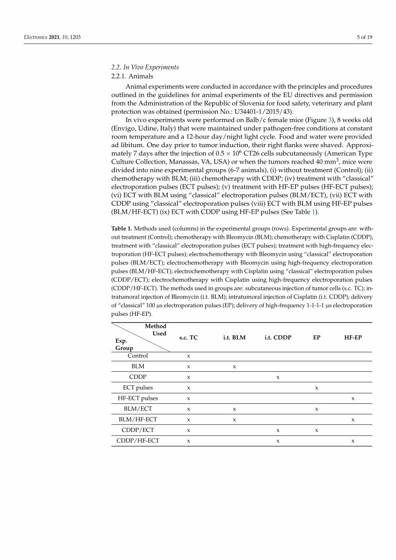
In vivo experiments were performed on Balb/c female mice (Figure 3), 8 weeks old(Envigo, Udine, Italy) that were maintained under pathogen-free conditions at constantroom temperature and a 12-hour day/night light cycle. Food and water were providedad libitum. One day prior to tumor induction, their right flanks were shaved. Approxi-mately 7 days after the injection of 0.5 × 10⁶ CT26 cells subcutaneously (American TypeCulture Collection, Manassas, VA, USA) or when the tumors reached 40 mm3, mice weredivided into nine experimental groups (6-7 animals), (i) without treatment (Control); (ii)chemotherapy with BLM; (iii) chemotherapy with CDDP; (iv) treatment with “classical”electroporation pulses (ECT pulses); (v) treatment with HF-EP pulses (HF-ECT pulses);(vi) ECT with BLM using “classical” electroporation pulses (BLM/ECT), (vii) ECT withCDDP using “classical” electroporation pulses (viii) ECT with BLM using HF-EP pulses(BLM/HF-ECT) (ix) ECT with CDDP using HF-EP pulses (See Table 1).
Table 1. Methods used (columns) in the experimental groups (rows). Experimental groups are: with-out treatment (Control); chemotherapy with Bleomycin (BLM); chemotherapy with Cisplatin (CDDP);treatment with “classical” electroporation pulses (ECT pulses); treatment with high-frequency elec-troporation (HF-ECT pulses); electrochemotherapy with Bleomycin using “classical” electroporationpulses (BLM/ECT); electrochemotherapy with Bleomycin using high-frequency electroporationpulses (BLM/HF-ECT); electrochemotherapy with Cisplatin using “classical” electroporation pulses(CDDP/ECT); electrochemotherapy with Cisplatin using high-frequency electroporation pulses(CDDP/HF-ECT). The methods used in groups are: subcutaneous injection of tumor cells (s.c. TC); in-tratumoral injection of Bleomycin (i.t. BLM); intratumoral injection of Cisplatin (i.t. CDDP); deliveryof “classical” 100 µs electroporation pulses (EP); delivery of high-frequency 1-1-1-1 µs electroporationpulses (HF-EP).
Exp.Group
MethodUsed
s.c. TC i.t. BLM i.t. CDDP EP HF-EP
Control x
BLM x x
CDDP x x
ECT pulses x x
HF-ECT pulses x x
BLM/ECT x x x
BLM/HF-ECT x x x
CDDP/ECT x x x
CDDP/HF-ECT x x x

Electronics 2021, 10, 1203 6 of 19
Figure 3. The design of the animal experiments. The accelerometer was attached to the right hindfoot of the mouse with adhesive tape. Electric pulses were generated by a newly-developed prototypedevice and delivered to the tumor on the right flank of the mouse by parallel plate electrodes.
2.2.2. Treatment Protocol
Two ECT protocols with BLM or CDDP were compared in vivo: ECT with well-established “classical” ECT pulses (8 × 100 µs) and ECT with HF-ECT pulses. Treatmentconsisted of intratumoral injection of BLM (Bleomycin medac, Medac, Wedel, Germany;5 µg; 40 µL) or CDDP (Cisplatin Kabi, 1 mg/mL, Fresenius Kabi AG, Bad Homburg,Germany; 40 µg; 40 µL), pulse delivery was followed 2 min later. For the application ofelectric pulses, parallel plate stainless-steel electrodes with 6 mm interelectrode distancewere used. A water-based gel was used to ensure good conductivity at the point of contactbetween electrodes and the skin overlaying the tumors. Physiological solution (40 µL) wasinjected in the control group and groups with electric pulses only. Mice were anesthetizedwith inhalation of 2% (v/v) isoflurane in pure oxygen in the induction chamber. Afterward,the mouse muzzle was placed under an inhalation tube to keep mice anesthetized duringthe treatment.
In “classical” ECT electric pulses were delivered with a commercially available Be-taTech electroporator (Electro cell B10, Leroy Biotech, Saint-Orens-de-Gameville, France).Electric pulse parameters: 780 V, 1.3 kV/cm voltage to distance ratio, eight 100 µs longpulses were applied in two perpendicular directions (4 + 4) at 1 Hz pulse repetition rate.In HF-ECT pulses were delivered by the newly developed prototype device. One combi-nation of electric pulse parameters was used (2.5 times higher voltage over distance [38]):eight bursts of 50 bipolar square wave pulses 1 µs-1 µs-1 µs-1 µs (duration of a positivepolarity-pause between pulse polarities-duration of a negative polarity-pause betweenbipolar pulses) at 1 Hz burst repetition rate resulting in equal total pulse amplitude timefor both pulse protocols. Pulse voltage amplitude in HF-ECT was 1950 V (3.25 kV/cmvoltage to distance ratio).
The therapeutic effect was estimated three times per week by measuring tumorvolume using a vernier caliper. Tumor volume was calculated according to: V = a ×b × c × π
6 , where a, b and c were three mutually orthogonal tumor diameters. Mice wereeuthanized when tumor volume reached 350 mm3. A Kaplan–Meier survival plot wasconstructed with the tumor volume of 300 mm3 representing the endpoint event. Statisticaltest Survival LogRank was performed on survival results (SigmaPlot, Systat Software, SanJose, CA, USA).
In the scope of this study, we also evaluated muscle contractions during pulse delivery.A triple axis accelerometer BMA220 (DFRobot, Shanghai, China) was connected to ArduinoUNO (Arduino, Boston, MA, USA). The accelerometer was taped with a micropore tape tothe right hind foot during pulse delivery. Software captured and saved the measurementsthat were analyzed post festum in Matlab. The absolute acceleration was calculated andgravitation was not excluded.
3. Results3.1. Device Performance
The measurement of monopolar and symmetric bipolar pulses with minimal pulseduration 200 ns and 1 µs are displayed in Figure 4. The capacitor charging voltage was setto 500 V and then raised to 4 kV in 500 V steps. Minimal duration pulses are limited by
Electronics 2021, 10, 1203 7 of 19
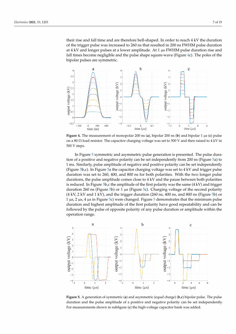
their rise and fall time and are therefore bell-shaped. In order to reach 4 kV the durationof the trigger pulse was increased to 260 ns that resulted in 200 ns FWHM pulse durationat 4 kV and longer pulses at a lower amplitude. At 1 µs FWHM pulse duration rise andfall times become negligible and the pulse shape square-wave (Figure 4c). The poles of thebipolar pulses are symmetric.
Figure 4. The measurement of monopolar 200 ns (a), bipolar 200 ns (b) and bipolar 1 µs (c) pulseon a 80 Ω load resistor. The capacitor charging voltage was set to 500 V and then raised to 4 kV in500 V steps.
In Figure 5 symmetric and asymmetric pulse generation is presented. The pulse dura-tion of a positive and negative polarity can be set independently from 200 ns (Figure 5a) to1 ms. Similarly, pulse amplitude of negative and positive polarity can be set independently(Figure 5b,c). In Figure 5a the capacitor charging voltage was set to 4 kV and trigger pulseduration was set to 260, 400, and 800 ns for both polarities. With the two longer pulsedurations, the pulse amplitude comes close to 4 kV and the pause between both polaritiesis reduced. In Figure 5b,c the amplitude of the first polarity was the same (4 kV) and triggerduration 260 ns (Figure 5b) or 1 µs (Figure 5c). Charging voltage of the second polarity(4 kV, 2 kV and 1 kV), and the trigger duration (260 ns, 400 ns, and 800 ns (Figure 5b) or1 µs, 2 µs, 4 µs in Figure 5c) were changed. Figure 5 demonstrates that the minimum pulseduration and highest amplitude of the first polarity have good repeatability and can befollowed by the pulse of opposite polarity of any pulse duration or amplitude within theoperation range.
Figure 5. A generation of symmetric (a) and asymmetric (equal charge) (b,c) bipolar pulse. The pulseduration and the pulse amplitude of a positive and negative polarity can be set independently.For measurements shown in subfigure (c) the high-voltage capacitor bank was added.
Electronics 2021, 10, 1203 8 of 19
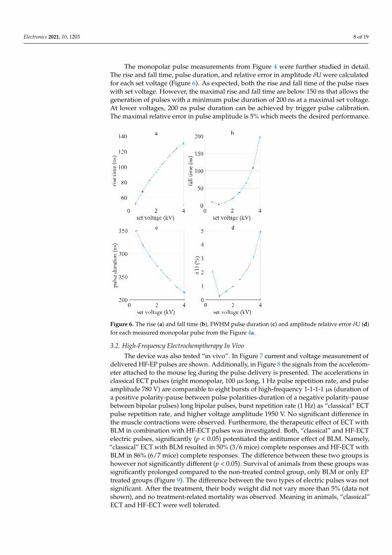
The monopolar pulse measurements from Figure 4 were further studied in detail.The rise and fall time, pulse duration, and relative error in amplitude δU were calculatedfor each set voltage (Figure 6). As expected, both the rise and fall time of the pulse riseswith set voltage. However, the maximal rise and fall time are below 150 ns that allows thegeneration of pulses with a minimum pulse duration of 200 ns at a maximal set voltage.At lower voltages, 200 ns pulse duration can be achieved by trigger pulse calibration.The maximal relative error in pulse amplitude is 5% which meets the desired performance.
Figure 6. The rise (a) and fall time (b), FWHM pulse duration (c) and amplitude relative error δU (d)for each measured monopolar pulse from the Figure 4a.
3.2. High-Frequency Electrochemptherapy In Vivo
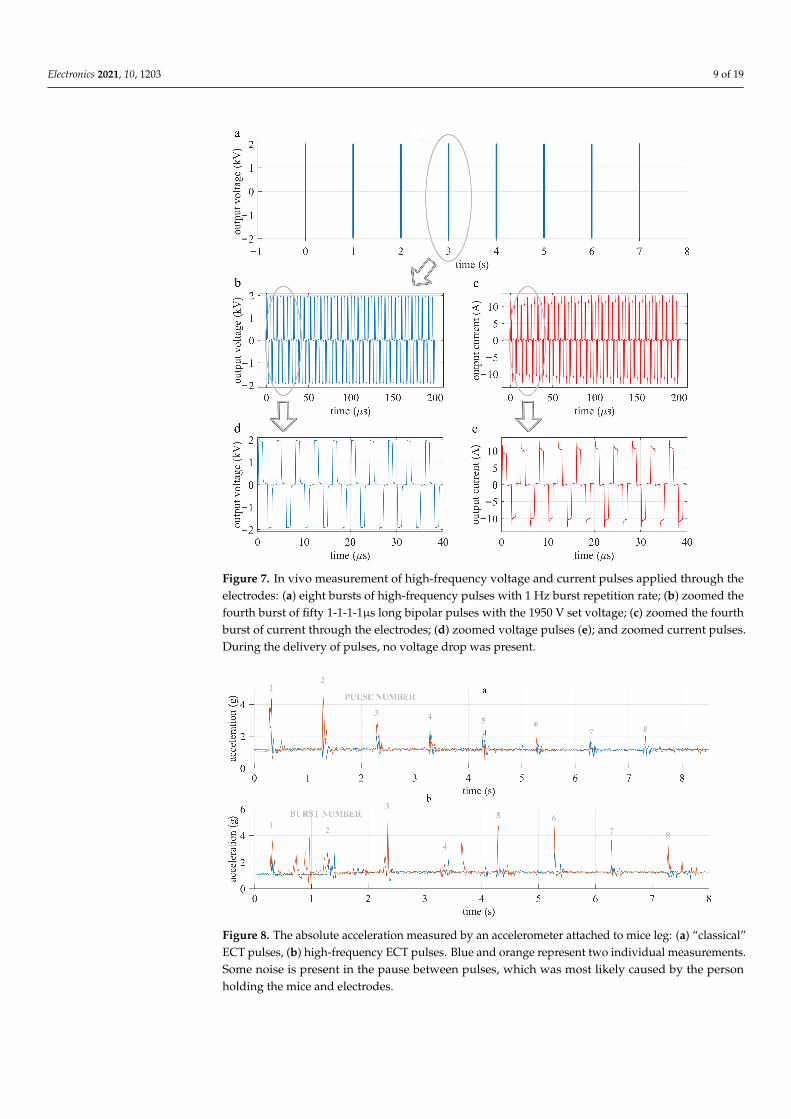
The device was also tested “in vivo”. In Figure 7 current and voltage measurement ofdelivered HF-EP pulses are shown. Additionally, in Figure 8 the signals from the accelerom-eter attached to the mouse leg during the pulse delivery is presented. The accelerations inclassical ECT pulses (eight monopolar, 100 µs long, 1 Hz pulse repetition rate, and pulseamplitude 780 V) are comparable to eight bursts of high-frequency 1-1-1-1 µs (duration ofa positive polarity-pause between pulse polarities-duration of a negative polarity-pausebetween bipolar pulses) long bipolar pulses, burst repetition rate (1 Hz) as “classical” ECTpulse repetition rate, and higher voltage amplitude 1950 V. No significant difference inthe muscle contractions were observed. Furthermore, the therapeutic effect of ECT withBLM in combination with HF-ECT pulses was investigated. Both, “classical” and HF-ECTelectric pulses, significantly (p < 0.05) potentiated the antitumor effect of BLM. Namely,“classical” ECT with BLM resulted in 50% (3/6 mice) complete responses and HF-ECT withBLM in 86% (6/7 mice) complete responses. The difference between these two groups ishowever not significantly different (p < 0.05). Survival of animals from these groups wassignificantly prolonged compared to the non-treated control group, only BLM or only EPtreated groups (Figure 9). The difference between the two types of electric pulses was notsignificant. After the treatment, their body weight did not vary more than 5% (data notshown), and no treatment-related mortality was observed. Meaning in animals, “classical”ECT and HF-ECT were well tolerated.
Electronics 2021, 10, 1203 9 of 19
Figure 7. In vivo measurement of high-frequency voltage and current pulses applied through theelectrodes: (a) eight bursts of high-frequency pulses with 1 Hz burst repetition rate; (b) zoomed thefourth burst of fifty 1-1-1-1µs long bipolar pulses with the 1950 V set voltage; (c) zoomed the fourthburst of current through the electrodes; (d) zoomed voltage pulses (e); and zoomed current pulses.During the delivery of pulses, no voltage drop was present.
Figure 8. The absolute acceleration measured by an accelerometer attached to mice leg: (a) “classical”ECT pulses, (b) high-frequency ECT pulses. Blue and orange represent two individual measurements.Some noise is present in the pause between pulses, which was most likely caused by the personholding the mice and electrodes.

Electronics 2021, 10, 1203 10 of 19
Figure 9. Survival of animals treated with “classical” and high-frequency ECT. Control (withouttreatment), chemotherapy with BLM, treatment with “classical” electroporation pulses (ECT pulses)or HF-EP pulses (HF-ECT pulses), with BLM using “classical” electroporation pulses (BLM/ECT) orHF-EP pulses (BLM/HF-ECT). The difference between BLM/ECT and BLM/HF-ECT is statisticallynot significant.
4. Discussion4.1. Device Performance
The developed device can generate 4 kV pulses, with theoretical maximal current131 A (Appendix A) and 200 ns minimal pulse duration, the maximal pulse repetition rate2 MHz, and the maximal burst repetition rate 1 MHz.
The device was first evaluated on an 80 Ω resistor. Monopolar, as well as symmetricand asymmetric bipolar pulses, were generated successfully (Figures 4 and 5). Rise and falltime increased with the capacitor charging voltage amplitude. Therefore, the shape of thepulse is less squared and more bell-shaped for 200 ns. The maximal relative error betweenthe set voltage and measured load voltage was less than 5%. With the extension of pulseduration, error decreased and pulse shape was more square-shaped (Figure 5a). However,a slight voltage amplitude drop can be seen in Figure 5a, which occurs due to the lack ofstored energy, which was improved with an additional capacitor bank (Figures 5c and 7).The capacitor bank stores a sufficient amount of energy, to prevent voltage drop of morethan 5% of the initial voltage. Figure 6d shows that amplitude relative error is reducedwith the reduction of the set voltage.
Because of poor literature hardware reporting of bipolar electroporators, a detailedcomparison is difficult. Regarding the output pulse parameters, the main innovation ofthe presented device is its ability to generate high-frequency asymmetric bipolar pulses.Maximal output pulse amplitude is 4 kV, Sano et al. [60,63–65] reached 5 kV. There is ourdevice with a 131 A maximal current that can also be used for in vivo IRE. In addition,the minimum pulse duration in combination with high-voltage (4 kV) and asymmetryrepresents an improvement with respect to other devices described in the literature so far.

Electronics 2021, 10, 1203 11 of 19
The design proposed in this paper enables faster development and spread of thehigh-frequency electroporation (H-FIRE, and HF-ECT). Because of asymmetrical pulsedelivery, it enables research of still unexplored pulse parameters in vitro and due to highmaximum current also in vivo. The developed generator consists of the newest componenttechnologies presented in Section 2 and Appendix A, that enable faster switching times di
dtin comparison to previously described solutions [37,54].
Arena et al. were one of the first who developed a custom high-frequency pulsegenerator, with a maximal output rating of the system equal to ±450 V and with a sufficientlevel of charge to deliver 20 A over a 100 µs bursts [35]. In more recent studies of the samegroup [66], the burst consisted of a train of 100 pulses of 1 µs duration and alternatingpolarity, with a delay of 2 µs between each pulse, and also the amplitude was increasedto 800 V. While Sano et al. managed to reduce the minimum pulse duration to 250 ns,the minimal delay between the change of pulse polarity was still 1 µs. Yao et al. developedan IRE bipolar electroporator and electrodes. Their device can generate pulses from 800 Vto 2 kV, with pulse duration from 1 µs up to 100 µs, but the burst repetition rate is equalto 1 s [59]. A similar device was used in the first clinical study using H-FIRE pulses byDong et al. [67]. Grainys et al. developed a bipolar symmetrical and asymmetrical electro-porator (±1 kV, 100 A) for in vitro electroporation and presented it in grater detail [54].For in vivo experiments, higher voltage amplitudes may be required. Mirai Medicalsdeveloped a CE-approved clinical electroporation generator named ePORE, which enablesa simple and reliable delivery of ultrashort electrical pulses up to 250 kHz. They report thatthe use of such pulses eliminates muscular contractions and pain associated with pulsedelivery [64,68].
4.2. High-Frequency Electrochemotherapy In Vivo
The developed device was used in an in vivo experiment treating subcutaneous tumorsin mice to evaluate tumor responses. Only half of the capacitor bank (four capacitors)was used because we used symmetric pulses. No voltage drop was detected in in vivomeasurements (Figure 7), i.e., energy storage was sufficient.
In vitro experiments by Scuderi et al. [38], showed that HF-EP could be used inECT. We here present the first in vivo experiments of HF-EP in ECT. Scuderi et al. [38]determined that 2.5-times higher electric field should be delivered with the HF-EP pulsesto obtain comparable cytotoxicity as with “classical” ECT pulses. Therefore, in our in vivoexperiments we applied the electric pulses with an amplitude of 1950 V for HF-ECT, whichresulted in 3.25 kV/cm (voltage to distance ratio). ECT with BLM and HF-EP proved atleast as effective as ECT with classic well-established electric pulses and 86% and 50%complete responses were observed, respectively. Additionally, preliminary data on ECTwith CDDP and HF-ECT pulses (n = 2) indicated that ECT with HF-EP is as effective asclassical ECT, resulting in 100% complete responses.
Additionally, muscle contractions present during HF-ECT were observed. Accelera-tions of mice hind leg during the pulse delivery were measured. In contrast to numerousreports [35,36,59,64,69] muscle contractions were similar in both protocols. Our findings inHF-EP are not in agreement with the published results of Ringel-Scaia et al. [70], whereH-FIRE caused no muscle contractions in comparison to IRE pulses delivered with needleelectrodes. However, we are the first to use plate electrodes in combination with HF-EP. Basedon another effect obtained it seems, the voltage amplitude for in vivo HF-ECT with plateelectrodes could be reduced. Lowering of amplitude may also affect muscle contractions.
5. Conclusions
The developed device operates in accordance with expectations, the maximal outputvoltage is 4 kV, the theoretical maximum current 131 A, minimal pulse duration 200ns, and the maximal pulse repetition rate is 2 MHz. It generates asymmetric bipolarpulses, i.e., pulse duration asymmetry, and pulse amplitude asymmetry can be regulated
Electronics 2021, 10, 1203 12 of 19
independently. Thus, the device enables research of still not completely understood effectsin the range of poorly investigated µs range of pulse parameters in vitro and in vivo.
The device was tested on an 80 Ω resistor and in vivo on a mouse tumor model. In bothcases, the desired performance was reached. Additionally, the movement of the mice’s legduring the pulse delivery was measured by an accelerometer in order to evaluate musclecontractions. In contrast to existing reports, we observed comparable muscle contractionsin both protocols used. Further in vivo measurements are needed, before final conclusions.Most importantly, HF-ECT with BLM and CDDP proved as effective as the established“classical” ECT with BLM and CDDP by using higher pulse amplitudes.
Author Contributions: Conceptualization, M.R. and D.M.; methodology, E.P., K.U., M.R., D.M. andG.S.; investigation, writing—original draft preparation, E.P., K.U. and M.R.; writing—review andediting, supervision, funding acquisition, M.R., D.M. and G.S. All authors have read and agreed tothe published version of the manuscript.
Funding: This research was funded by the Slovenian Research Agency (ARRS) (MRIC UL IP-0510,P2-0249, P3-0003, J2-9227 and funding for Junior Researchers to Eva Pirc).
Institutional Review Board Statement: Animal experiments were conducted in accordance with theprinciples and procedures outlined with the guidelines for animal experiments of the EU directivesand the permission from The Administration of the Republic of Slovenia for food safety, veterinaryand plant protection (permission No.: U34401-1/2015/43).
Data Availability Statement: The data presented in this study are available on request from thecorresponding author.
Conflicts of Interest: The authors declare no conflict of interest. The funders had no role in the designof the study; in the collection, analyses, or interpretation of data; in the writing of the manuscript, orin the decision to publish the results.
Abbreviations
The following abbreviations are used in this manuscript:
IRE irreversible electroporationECT electrochemotherapyBLM bleomycinCDDP cisplatinH-FIRE High-Frequency IRreversible ElectroporationHF-EP high-frequency electroporationAF atrial fibrillationPFA pulsed field ablationHF-ECT high-frequency electrochemotherapyFWHM Full-Width at Half-Maximum
Appendix A. Details in Generator Development
In our previously published paper [61], we already made an analysis and comparisonbetween the most commonly used semiconductor switching technologies in pulse gener-ators. We again chose the Silicon Carbide (SiC) MOSFET technology, which we believeis the most suitable for high-voltage and high current short pulse duration generators.After the analysis, the manufacturer started to produce even more suitable SiC MOSFETs(C2M0045170D, Cree, Silicon Drive Durham, NC, USA) with a drain to source voltage1700 V and pulse drain current 160 A. Only three MOSFET in series are needed in orderto generate desired 4 kV pulses on the output. When designing a driving circuit for SiCMOSFET it is important to consider SiC MOSFETs special characteristics [71]. SiC MOS-FET’s have low transconductance, therefore must be driven with high-voltage difference.For fast switching high dV
dt of the Vgs is needed, meaning the driving circuit should havelow impedance. For optimal switching also stray impedance of the driving circuit must be

Electronics 2021, 10, 1203 13 of 19
minimal, therefore, lines connecting the SiC MOSFET driver to power supply capacitorsand gate terminal should be as short as possible.
The development of a versatile pulse generator started with the selection of theappropriate electronic components. In this paper we intended to upgrade the drivingcircuit presented before [61], mainly by reaching higher dV
dt , meaning we can generateshorter pulses on the output. Therefore, we analyzed available drivers and optical isolators.
Appendix A.1. Driver and Optical Insulation
In order to develop a generator that would be able to generate a few hundred nanosec-onds wide square wave pulses, with the best possible repeatability (good time precision)and at the same time high accuracy, we made an analysis and comparison between the mostcommonly used drivers and optical isolators in high-voltage pulse generators. We werelooking for a driver and optical isolator with a short minimal FWHM (Full-Width Half-Maximum) and at the same time high common-mode transient immunity (CMTI— dV
dt ),because minimal FWHM and high CMTI define the electroporator output minimal pulsewidth. The pulse width jitter should be low for good time precision. Therefore we evaluatedthe minimal FWHM and calculated the pulse width jitter of each component separately.
On the basis of the following characteristics: maximum working isolation voltage,CMTI, maximum pulse width distortion, maximal propagation delay skew, and maxi-mal propagation delay, collected from the datasheets, we picked the following opticalisolators: HCPL-0723(Avago Technologies, San Jose, CA, USA), HFBR 0508Z (Broadcom,San Jose, CA, USA), ADuM210N0BRIZ (Analog Devices, Wilmington, MA, USA); anddrivers: IXDN609SI (IXYS, Beverly, MA, USA), MIC4422YM (Micrel, San Jose, CA, USA),UCC27531DBVT (Texas Instruments, Dallas, TX, USA). Additionally, we also evaluatedADuM4223 (Analog Devices, Wilmington, MA, USA) and Si826BAD-C-IS (Silicon labs,Austin, TX, USA), which are a combination of a driver and optocoupler in one chip. For theevaluation we used an evaluation board offered by the manufacturer (if available), oth-erwise, we made a custom board in accordance with the manufacturer’s instructions orsimilar to other designs.
All the components under test were triggered with a function generator (33220A,Agilent Technologies, Santa Clara, CA, USA) set to: 5 Vpp, with 2.5 Vpp offset, frequency10 Hz, pulse rise time 5 ns, pulse width 20 ns and number of pulses 30. The minimaltrigger FWHM is 20 ns if the component under test did not generate the output pulse,the trigger FWHM was increased by steps of 10 ns. In the case of optical isolation evaluation,the output was measured with a high precision differential probe TDP1000 (Tektronix,Beaverton, OR, USA) and displayed on the oscilloscope MSO4104 (Tektronix, Beaverton,OR, USA). While, for the evaluation of driver, the MOSFET in series connected to a chargedcapacitor and 100 Ω load resistor (TFSF100RJE-ND, Ohmite, Warrenville, IL, USA), wasadded and the pulse on the MOSFET was measured, with a high-voltage differentialprobe ADP305 (Lecroy, Chestnut Ridge, NY, USA) and displayed on the oscilloscopeWavepro7300A (Lecroy, Chestnut Ridge, NY, USA). The capacitor was charged with ahigh-voltage generator MCP 350–1250 (FuG Elektronik GmbH, Schechen, Germany).
Minimal measured FWHM and jitter for optical solutions are shown in the Table A1and for drivers in Table A2. The minimal FWHM in the Tables A1 and A2 is defined as anaverage of thirty measured FWHM’s at minimal trigger FWHM and jitter is defined as thedifference between maximal and minimal measured FWHM at minimal trigger FWHM.Further in the paper for easier reading instead of FWHM term pulse width is used.

Electronics 2021, 10, 1203 14 of 19
Table A1. Optical Isolators: Mean values of minimal FWHM further defined as pulse width and jitterfor a set of 30 measurements, for different optical isolators under test.
Component Set/MeasuredTrigger Width (ns)
Output PulseWidth (ns) Jitter (ns)
HCPL-0723 20/19.10 18.53 1.04ADuM4223 50/49.45 40.98 0.75
Si826BAD-C-IS 30/28.65 13.84 0.29HFBR 0508Z 20/19.25 30.2 0.93
ADuM210N0BRIZ 20/21.37 18.28 0.26
The test showed ADuM4223 and Si826BAD-C-IS are less suitable for our application,due to high pulse width. Therefore we excluded them from further testing. HCPL-0723has the highest jitter and according to the datasheet, also the lowest CMTI, which is only10 kV
µs . HFBR 0508Z is actually a set of fiberoptic transmitters and receivers connected witha plastic fiber optic cable. Due to the higher output pulse width and design complexity ofHFBR 0508Z we finally deiced to use ADuM210N0BRIZ in our electroporator, because ofits high CMTI, which is 100 kV
µs and its best test performance.IXDN609SI was the only driver that can be triggered with a 20 ns pulse, however,
it has the biggest jitter. Because we wanted to develop a device that would be able togenerate pulses as short as 200 ns, IXDN609SI was chosen for achieving our goal, the mostappropriate component among the tested devices. The final driving circuit topology wasalmost the same as presented in Pirc et al. [61]. Only two isolated DC-DC converters werereplaced with one isolated DC-DC converter MGJ2D052005SC (Murata Power Solutions,Westborough, MA, USA) and the optocoupler was changed. The optimal gate resistorvalue was determined through testing in accordance with the performance requirements.
Table A2. Drivers: Mean values of minimal FWHM and jitter for a set of 30 measurements, for differ-ent drivers under test.
Component Set/MeasuredTrigger Width (ns)
Output PulseWidth (ns) Jitter (ns)
IXDN609SI 20/20.4 44.36 9.45ADuM4223 70/69.99 67.53 1.98
UCC27531DBVT 110/109.23 57.27 3.8MIC4422YM 40/39.82 125.26 2.55
Appendix A.2. Testing MOSFETs in Series
After the selection of appropriate components, a monopolar prototype was built. Weconnected three MOSFETs in series in order to evaluate the high-voltage (4 kV) switching,the feasibility of the series, and selected components. In Figure A1, a basic topology of theseries is presented. Capacitors C1 (940C20W1K-F, Cornell Dubilier Electronics, Liberty, SC,USA) are charged by an HV power supply HCP350-6K5 (FuG Elektronik GmbH, Schechen,Germany) and when triggered discharged by a Rload 150 Ω resistor (AZ151KE, Ohmite,Warrenville, IL, USA). In parallel to each SiC MOSFET, a resistor R1 (SM102031004FE,Ohmite, Warrenville, IL, USA) is added, which ensures the uniform distribution of voltageover all three MOSFETs. In order to be able to generate pulses as short as 200 ns on theoutput load, rise and fall time should be lower than 50 ns. With testing, we determined theminimal gate resistor (Rg) value that still keeps the circuit stable as 6.8 Ω. We also testeddifferent strategies eg. turning on lower MOSFET slower than the other two, however,in the end, the optimal results were obtained when all three MOSFETs had the same valueof Rg.
Electronics 2021, 10, 1203 15 of 19
S
D.C.
D.C.
D.C.
Vtrig
R1
R1
R1
Rload
R2 C1
R2 C1
R2 C1
4 kV
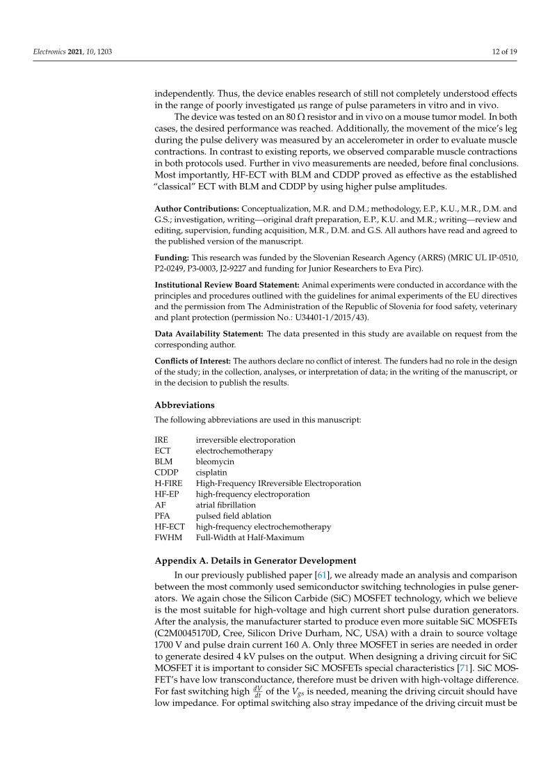
Figure A1. Test circuit of three MOSFETs in series, each MOSFET has its own driving circuit whichis in the figure presented as a box marked with initials D.C.. Dashed line, defines a a box S, four ofthose boxes are for the purpose of bipolar pulse generation connected in H-bridge (Figure 1).
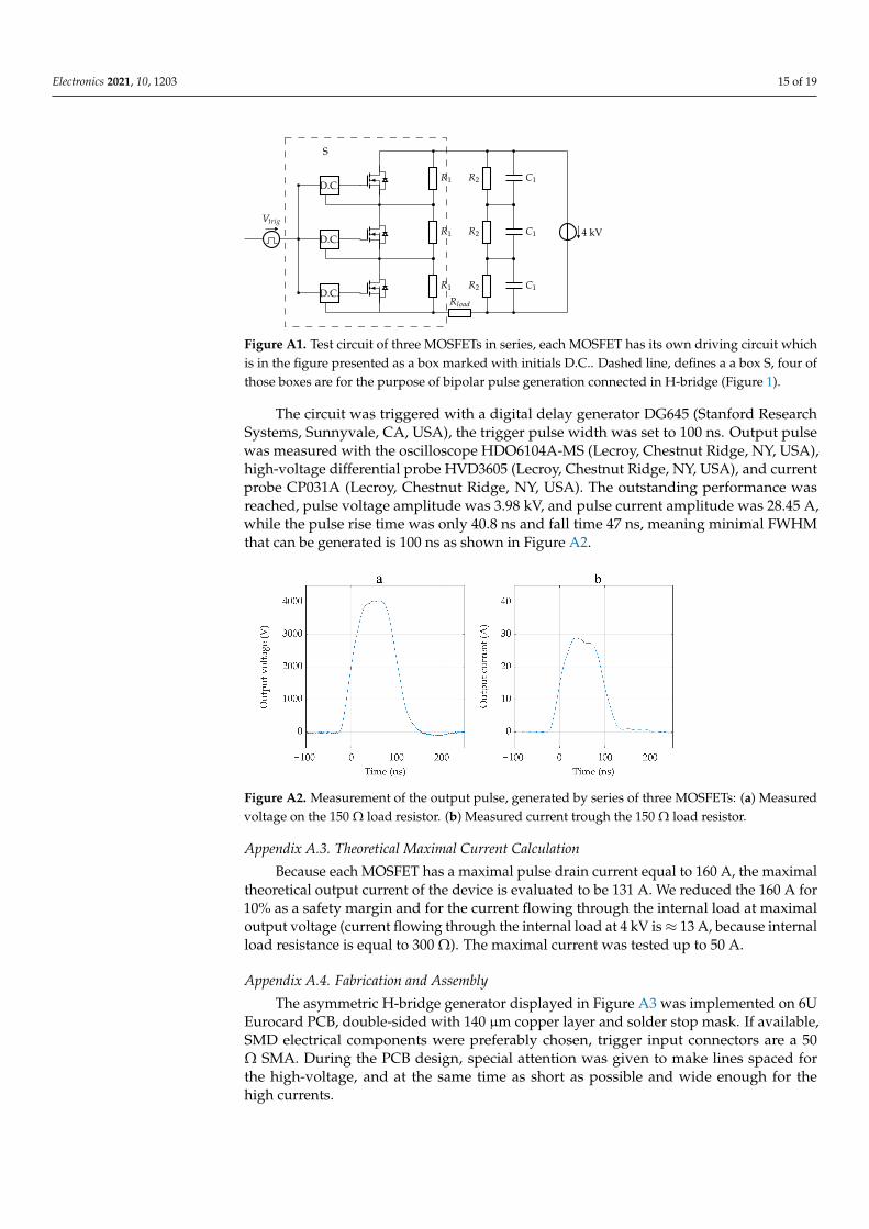
The circuit was triggered with a digital delay generator DG645 (Stanford ResearchSystems, Sunnyvale, CA, USA), the trigger pulse width was set to 100 ns. Output pulsewas measured with the oscilloscope HDO6104A-MS (Lecroy, Chestnut Ridge, NY, USA),high-voltage differential probe HVD3605 (Lecroy, Chestnut Ridge, NY, USA), and currentprobe CP031A (Lecroy, Chestnut Ridge, NY, USA). The outstanding performance wasreached, pulse voltage amplitude was 3.98 kV, and pulse current amplitude was 28.45 A,while the pulse rise time was only 40.8 ns and fall time 47 ns, meaning minimal FWHMthat can be generated is 100 ns as shown in Figure A2.
Figure A2. Measurement of the output pulse, generated by series of three MOSFETs: (a) Measuredvoltage on the 150 Ω load resistor. (b) Measured current trough the 150 Ω load resistor.
Appendix A.3. Theoretical Maximal Current Calculation
Because each MOSFET has a maximal pulse drain current equal to 160 A, the maximaltheoretical output current of the device is evaluated to be 131 A. We reduced the 160 A for10% as a safety margin and for the current flowing through the internal load at maximaloutput voltage (current flowing through the internal load at 4 kV is ≈ 13 A, because internalload resistance is equal to 300 Ω). The maximal current was tested up to 50 A.
Appendix A.4. Fabrication and Assembly
The asymmetric H-bridge generator displayed in Figure A3 was implemented on 6UEurocard PCB, double-sided with 140 µm copper layer and solder stop mask. If available,SMD electrical components were preferably chosen, trigger input connectors are a 50Ω SMA. During the PCB design, special attention was given to make lines spaced forthe high-voltage, and at the same time as short as possible and wide enough for thehigh currents.

Electronics 2021, 10, 1203 16 of 19
Figure A3. The developed prototype device. The developed H-bridge circuit is implemented ondouble-sided PCB 6U board and installed on a custom-made capacitor bank. The black box is acapacitor bank discharge circuit.
References1. Kotnik, T.; Rems, L.; Tarek, M.; Miklavcic, D. Membrane Electroporation and Electropermeabilization: Mechanisms and Models.
Annu. Rev. Biophys. 2019, 48, 63–91. [CrossRef] [PubMed]2. Jiang, C.; Davalos, R.V.; Bischof, J.C. A Review of Basic to Clinical Studies of Irreversible Electroporation Therapy. IEEE Trans.
Biomed. Eng. 2015, 62, 4–20. [CrossRef] [PubMed]3. Haberl, S.; Miklavcic, D.; Serša, G.; Frey, W.; Rubinsky, B. Cell Membrane Electroporation—Part 2: The Applications. IEEE Electr.
Insul. Mag. 2013, 29, 29–37. [CrossRef]4. Geboers, B.; Scheffer, H.J.; Graybill, P.M.; Ruarus, A.H.; Nieuwenhuizen, S.; Puijk, R.S.; van den Tol, P.M.; Davalos, R.V.; Rubinsky,
B.; de Gruijl, T.D.; et al. High-Voltage Electrical pulses in oncology: Irreversible electroporation, electrochemotherapy, geneelectrotransfer, electrofusion, and electroimmunotherapy. Radiology 2020, 295, 254–272. [CrossRef]
5. Golberg, A.; Sack, M.; Teissie, J.; Pataro, G.; Pliquett, U.; Saulis, G.; Töpfl, S.; Miklavcic, D.; Vorobiev, E.; Frey, W. Energy-EfficientBiomass Processing with Pulsed Electric Fields for Bioeconomy and Sustainable Development. Biotechnol. Biofuels 2016, 9, 94.[CrossRef]
6. Kotnik, T.; Frey, W.; Sack, M.; Haberl, Meglic, S.; Peterka, M.; Miklavcic, D. Electroporation-based applications in biotechnology.Trends Biotechnol. 2015, 33, 480–488. [CrossRef]
7. Hui, S.W. Effects of Pulse Length and Strength on Electroporation Efficiency. In Plant Cell Electroporation and Electrofusion Protocols;Springer: New York, NY, USA, 1995; pp. 29–40.
8. Miklavcic, D.; Towhidi, L. Numerical study of the electroporation pulse shape effect on molecular uptake of biological cells.Radiol. Oncol. 2010, 44, 34–41. [CrossRef]
9. Weav, J.C.; Smith, K.C.; Esser, A.T.; Son, R.S.; Gowrishankar, T.R. A brief overview of electroporation pulse strength-durationspace: A region where additional intracellular effects are expected. Bioelectrochemistry 2012, 87, 236–243.
10. Reberšek, M.; Miklavcic, D. Concepts of electroporation pulse generation and overview of electric pulse generators for cell andtissue electroporation. In Advanced Electroporation Techniques in Biology and Medicine; Pakhomov, A.G., Miklavcic, D., Markov, M.S.,Eds.; CRC Press: Boca Raton, FL, USA, 2010; pp. 323–339.
11. Reberšek, M.; Miklavcic, D. Advantages and Disadvantages of Different Concepts of Electroporation Pulse Generation. Automatika2011, 52, 1219. [CrossRef]
12. Šel, D.; Cukjati, D.; Batiuskaite, D.; Slivnik, T.; Mir, L.M.; Miklavci, D. Sequential finite element model of tissue electropermeabi-lization. IEEE Trans. Bio-Med. Eng. 2005, 2, 816–827. [CrossRef]
13. Ivorra, A.; Al-Sakere, B.; Rubinsky, B.; Mir, L.M. In Vivo Electrical Conductivity Measurements during and after TumorElectroporation: Conductivity Changes Reflect the Treatment Outcome. Phys. Med. Biol. 2009, 54, 5949. [CrossRef]
14. Neal, R.E., 2nd; Garcia, P.A.; Robertson, J.L.; Davalos, R.V. Experimental Characterization and Numerical Modeling of TissueElectrical Conductivity during Pulsed Electric Fields for Irreversible Electroporation Treatment Planning. IEEE Trans. Biomed.Eng. 2012, 59, 1076–1085. [CrossRef]
15. Pirc, E.; Balosetti, B.; Miklavcic, D.; Reberšek, M. Electronic emulator of biological tissue as an electrical load during electroporation.Appl. Sci. 2020, 10, 3101. [CrossRef]
16. Weinert, R.L.; Ramos, A. Applied Electromagnetic Research Group Electroporation threshold, conductivity and memory effect inrat liver. Biomed. Signal Process. Control 2021, 64, 102275. [CrossRef]
Electronics 2021, 10, 1203 17 of 19
17. Lorenzo, M.F.; Bhonsle, S.P.; Arena, C.B.; Davalos, R.V. Rapid impedance spectroscopy for monitoring tissue impedance,temperature, and treatment outcome during electroporation-based therapies. IEEE Trans. Biomed. Eng. 2020, 68, 1536–1546.[CrossRef]
18. Miklavcic, D.; Serša, G.; Brecelj, E.; Gehl, J.; Soden, D.; Bianchi, G.; Ruggieri, P.; Rossi, C.R.; Campana, L.G.; Jarm, T. Elec-trochemotherapy: technological advancements for efficient electroporation-based treatment of internal tumors. Med. Biol. Eng.Comput. 2012, 50, 1213–1225. [CrossRef]
19. Marty, M.; Serša, G.; Garbay, J.R.; Gehl, J.; Collins, C.G.; Snoj, M.; Billarda, V.; Geertsenc, P.F.; Larkind, J.O.; Miklavcic, D.; et al.Electrochemotherapy—An easy, highly effective and safe treatment of cutaneous and subcutaneous metastases: Results of ESOPE(European Standard Operating Procedures of Electrochemotherapy) study. Eur. J. Cancer Suppl. 2006, 4, 3–13. [CrossRef]
20. Mir, L.M.; Gehl, J.; Serša, G.; Collins, C.G.; Garbay, J.-R.; Billard, V.; Geertsen, P.F.; Rudolf, Z.; O’Sullivan, G.C.; Marty, M. StandardOperating Procedures of the Electrochemotherapy: Instructions for the Use of Bleomycin or Cisplatin Administered EitherSystemically or Locally and Electric Pulses Delivered by the CliniporatorTM by Means of Invasive or Non-Invasive Electrodes.EJC Suppl. 2014, 4, 14–25. [CrossRef]
21. Gehl, J.; Serša, G.; Wichmann Matthiessen, L.; Muir, T.; Soden, D.; Occhini, A.; Quaglino, P.; Curatolo, P.; Campana, L.G.; Kunte,C.; et al. Updated standard operating procedures for electrochemotherapy of cutaneous tumours and skin metastases. ActaOncol. 2018, 57, 874–882. [CrossRef]
22. Campana, L.G.; Edhemovic, I.; Soden, D.; Perrone, A.M.; Scarpa, M.; Campanacci, L.; Cemažar, M.; Valpione, S.; Miklavcic, D.;Mocellin, S.; et al. Electrochemotherapy—Emerging applications technical advances, new indications, combined approaches, andmulti-institutional collaboration. Eur. J. Surg. Oncol. 2019, 45, 92–102. [CrossRef]
23. Aycock, K.N.; Davalos, R.V. Irreversible Electroporation: Background, Theory, and Review of Recent Developments in ClinicalOncology. Bioelectricity 2019, 1, 214–234. [CrossRef]
24. Sugrue, A.; Vaidya, V.; Witt, C.; DeSimone, C.V.; Yasin, O.; Maor, E.; Killu, A.M.; Kapa, S.; McLeod, C.J.; Miklavcic, D.; et al.Irreversible electroporation for catheter-based cardiac ablation: A systematic review of the preclinical experience. J. Interv. Card.Electrophysiol. 2019, 55, 251–265. [CrossRef]
25. Jiang, C.; Shao, Q.; Bischofet, J. Pulse Timing during Irreversible Electroporation Achieves Enhanced Destruction in a HindlimbModel of Cancer. Ann. Biomed. Eng. 2015, 43, 88795. [CrossRef]
26. Rubinsky, B. Irreversible Electroporation in Medicine. Technol. Cancer Res. Treat. 2007, 6, 255–259. [CrossRef]27. Al-Sakere, B.; Bernat, C.; Andre, F.; Connault, E.; Opolon, P.; Davalos, R.V.; Mir, L.M. A Study of the Immunological Response to
Tumor Ablation with Irreversible Electroporation. Technol. Cancer Res. Treat. 2014, 6, 301–305. [CrossRef]28. Rubinsky, B.; Onik, G.; Mikus, P. Irreversible Electroporation: A New Ablation Modality—Clinical Implications. Technol. Cancer
Res. Treat. 2007, 6, 37–48. [CrossRef] [PubMed]29. Scheffer, H.J.; Stam, A.G.M.; Geboers, B.; Vroomen, L.G.P.H.; Ruarus, A.; de Bruijn, B.; van den Tol, M.P.; Kazemier, G.; Meijerink,
M.R.; de Gruijl, T.D. Irreversible electroporation of locally advanced pancreatic cancer transiently alleviates immune suppressionand creates a window for antitumor T cell activation. OncoImmunology 2019, 8, 1652532. [CrossRef]
30. Garcia, P.A.; Davalos, R.V.; Miklavcic, D. A numerical investigation of the electric and thermal cell kill distributions inelectroporation-based therapies in tissue. PLoS ONE 2014, 9, e103083. [CrossRef]
31. Davalos, R.V.; Mir, L.M.; Rubinsky, B. Tissue Ablation with Irreversible Electroporation. Ann Biomed Eng 2005, 33, 223. [CrossRef]32. Ball, C.; Thomson, K.R.; Kavnoudias, H. Irreversible Electroporation: A New Challenge in Out of Operating Theater Anesthesia.
Anesth. Analg. 2010, 110, 13051309. [CrossRef]33. Landström, F.J.; Nilsson, C.O.S.; Crafoord, S.; Reizenstein, J.A.; Adamsson, G.-B.M.; Löfgren, L.A. Electroporation Therapy of
Skin Cancer in the Head and Neck Area. Dermatol. Surg. 2010, 36, 124550. [CrossRef]34. Mali, B.; Jarm, T.; Jager, F.; Miklavcic, D. An algorithm for synchronization of in vivo electroporation with ECG. J. Med Eng.
Technol. 2005, 29, 28896. [CrossRef] [PubMed]35. Arena, C.B.; Sano, M.B.; Rossmeisl, JHJr, Caldwell, J.L.; Garcia, P.A.; Rylander, M.N.; Davalos, R.V. High-Frequency Irreversible
Electroporation (H-FIRE) for Non-Thermal Ablation without Muscle Contraction. BioMedical Eng. OnLine 2012, 10, 102. [CrossRef]36. Arena, C.B.; Davalos, R.V. Advances in Therapeutic Electroporation to Mitigate Muscle Contractions. J. Membr. Sci. Technol. 2012,
2, 1–3. [CrossRef]37. Sweeney, D.C.; Reberšek, M.; Dermol, J.; Rems, L.; Miklavcic, D.; Davalos, R.V. Quantification of cell membrane permeability
induced by monopolar and high-frequency bipolar bursts of electrical pulses. Biochim. Et Biophys. Acta (BBA) Biomembr. 2016,1858, 2689–2698. [CrossRef] [PubMed]
38. Scuderi, M.; Reberšek, M.; Miklavcic, D.; Dermol-Cerne, J. The use of high-frequency short bipolar pulses in cisplatin elec-trochemotherapy in vitro. Radiol. Oncol. 2019, 53, 194–205. [CrossRef] [PubMed]
39. Lavee, J.; Onik, G.; Mikus, P.; Rubinsky, B. A novel nonthermal energy source for surgical epicardial atrial ablation: Irreversibleelectroporation. Heart Surg. Forum. 2007, 10, E162–E167. [CrossRef]
40. Reddy, V.Y.; Neuzil, P.; Koruth, J.S.; Petru, J.; Funosako, M.; Cochet, H.; Sediva, L.; Chovanec, M.; Dukkipati, S.R.; Jais, R. PulsedField Ablation for Pulmonary Vein Isolation in Atrial Fibrillation. J. Am. Coll. Cardiol. 2019, 74, 315–326. [CrossRef]
41. Ramirez, F.D.; Reddy, V.Y.; Viswanathan, R.; Hocini, M.; Jaïs, P. Emerging Technologies for Pulmonary Vein Isolation. Circ. Res.2020, 127, 170–183. [CrossRef]
Electronics 2021, 10, 1203 18 of 19
42. Stewart, M.T.; Haines, D.E.; Miklavcic, D.; Kos, B.; Kirchhof, N.; Barka, N.; Mattison, L.; Martien, M.; Onal, B.; Howard, B.; etal. Safety and chronic lesion characterization of pulsed field ablation in a Porcine model. J. Cardiovasc. Electrophysiol. 2021,32, 958–969. [CrossRef]
43. Golberg, A.; Rubinsky, B. Towards Electroporation Based Treatment Planning Considering Electric Field Induced MuscleContractions. Technol. Cancer Res. Treat. 2012, 11, 189–201. [CrossRef] [PubMed]
44. Pakhomova, O.N.; Gregory, B.W.; Khorokhorina, V.A.; Bowman, A.M.; Xiao, S.; Pakhomov, A.G. Electroporation-InducedElectrosensitization. PLoS ONE 2011, 6, e17100. [CrossRef]
45. Pakhomova, O.N.; Gregory, B.W.; Pakhomov, A.G. Facilitation of Electroporative Drug Uptake and Cell Killing by Electrosensiti-zation. J. Cell. Mol. Med. 2013, 17, 154–159. [CrossRef]
46. Pakhomov, A.G.; Semenov, I.; Xiao, S.; Pakhomova, O.N.; Gregory, B.; Schoenbach, K.H.; Ullery, J.C.; Beier, H.T.; Rajulapati, S.R.;Ibey, B.L. Cancellation of Cellular Responses to Nanoelectroporation by Reversing the Stimulus Polarity. Ther. Clin. Risk Manag.2014, 71, 443141. [CrossRef]
47. Ibey, B.L.; Ullery, J.; Pakhomova, O.N.; Roth, C.C.; Semenov, I.; Beier, H.T.; Tarango, M.; Xiao, S.; Schoenbach, K.; Pakhomov, A.G.Bipolar nanosecond electric pulses are less efficient at electropermeabilization and killing cells than monopolar pulses. Biochem.Biophys. Res. Commun. 2014, 443, 568573. [CrossRef]
48. Dermol, J.; Pakhomova, O.N.; Pakhomov, A.G.; Miklavcic, D. Cell Electrosensitization Exists Only in Certain ElectroporationBuffers. PLoS ONE 2016, 11, e0159434. [CrossRef]
49. Polajžer, T.; Dermol-Cerne, J.; Reberšek, M.; O’Connor, R.; Miklavcic, D. Cancellation effect is present in high-frequency reversibleand irreversible electroporation. Bioelectrochemistry 2019, 132, 1–11. [CrossRef] [PubMed]
50. Van Es, R.; Konings, M.K.; Du Pré, M.C.; Neven, K.; van Wessel, H.; van Driel, V.J.H.M.; Westra, A.H.; Doevendans, P.A.F.;Wittkampf, F.H.M. High-frequency irreversible electroporation for cardiac ablation using an asymmetrical waveform. BioMedEng. OnLine 2019, 18, 1–13. [CrossRef]
51. Novickij, V.; Grainys, A.; Butkus, P.; Tolvaišiene, S.; Švediene, J.; Paškevicius, A.; Novickij, J. High-frequency submicrosecondelectroporator. Biotechnol. Biotechnol. Equip. 2016, 30, 1–7. [CrossRef]
52. Redon, L.M.; Zahyka, M.; Kandratsyeu, A. Solid-State Generation of High-Frequency Burst of Bipolar Pulses for MedicalApplications. IEEE Trans. Plasma Sci. 2019, 47, 4091–4095. [CrossRef]
53. Petkovšek, M.; Nastran, J.; Voncina, D.; Zajec, P.; Miklavcic, D.; Serša, G. High Voltage Pulse Generation [Electroporation].Electron. Lett. 2002, 38, 680–682. [CrossRef]
54. Grainys, A.; Novickij, V.; Novickij, J. High-power bipolar multilevel pulsed electroporator. Instrum. Sci. Technol. 2016, 44, 65–72.[CrossRef]
55. Pirc, E.; Reberšek, M.; Miklavcic, D. Dosimetry in Electroporation-Based Technologies and Treatments. In Dosimetry inBioelectromagnetics; Markov, M., Ed.; CRC Press, Taylor & Francis Group: Boca Raton, FL, USA, 2017; pp. 233–268.
56. Colombo, G.L.; Di Matteo, S.; Mir, L.M. Cost-Effectiveness Analysis of Electrochemotherapy with the Cliniporatortrade Mark vsOther Methods for the Control and Treatment of Cutaneous and Subcutaneous Tumors. Ther. Clin. Risk Manag. 2008, 4, 541–548.[CrossRef]
57. Pirc, E.; Federici, C.; Bošnjak, M.; Peric, B.; Reberšek, M.; Pecchia, L.; Glumac, N.; Cemažar, M.; Snoj, M.; Serša, G.; et al. Earlycost-effectiveness analysis of electrochemotherapy as a prospect treatment modality for skin melanoma. Clin. Ther. Accept. Publ.2020, 42, 1535–1548. [CrossRef]
58. Canadian Agency for Drugs and Technologies in Health. Irreversible Electroporation for Tumors of the Pancreas or Liver: Review ofClinical and Cost-Effectiveness; Canadian Agency for Drugs and Technologies in Health: Ottawa, ON, Canada, 2016.
59. Yao, C.; Dong, S.; Zhao, Y.; Lv, Y.; Liu, H.; Gong, L.; Ma, J.; Wang, H.; Sun, Y. Bipolar Microsecond Pulses and Insulated NeedleElectrodes for Reducing Muscle Contractions During Irreversible Electroporation. IEEE Trans. Biomed. Eng. 2017, 64, 2924–2937.
60. Sano, M.B.; Arena, C.B.; Bittleman, K.B.; De Witt, M.R.; Cho, H.J.; Szot, C.S.; Saur, D.; Cissell, J.M.; Robertson, J.; Lee, Y.W.; et al.Bursts of Bipolar Microsecond Pulses Inhibit Tumor Growth. Sci. Rep. 2015, 5, 14999. [CrossRef]
61. Pirc, E.; Miklavcic, D.; Reberšek, M. Nanosecond Pulse Electroporator With Silicon Carbide mosfets: Development andEvaluation. IEEE Trans. Biomed. Eng. 2019, 66, 3526–3533. [CrossRef]
62. Campana, L.G.; Cesari, M.; Dughiero, F.; Forzan, M.; Rastrelli, M.; Rossi, C.R.; Sieni, E.; Tosi, A.L. Electrical resistance of humansoft tissue sarcomas: An ex vivo study on surgical specimens. Med. Biol. Eng. Comput. 2016, 54, 773–787. [CrossRef]
63. Sano, M.B.; Arena, C.B.; De Witt, M.R.; Saur, D.; Davalos, R.V. In-vitro bipolar nano—And microsecond electro-pulse bursts forirreversible electroporation therapies. Bioelectrochemistry 2014, 100, 69–79. [CrossRef]
64. Sano, M.B.; Fan, R.E.; Cheng, K.; Saenz, Y.; Sonn, G.A.; Hwang, G.L.; Xing, L. Reduction of Muscle Contractions duringIrreversible Electroporation Therapy Using High-Frequency Bursts of Alternating Polarity Pulses: A Laboratory Investigation inan Ex Vivo Swine Model. J. Vasc. Interv. Radiol. 2015, 29, 893–898. [CrossRef]
65. Kaufman, J.D.; Fesmire, C.C.; Petrella, R.A.; Fogle, C.A.M.; Xing, L.; Gerber, D.; Sano, M.B. High-Frequency IrreversibleElectroporation Using 5000-V Waveforms to Create Reproducible 2-and 4-cm Ablation Zones—A Laboratory Investigation UsingMechanically Perfused Liver. J. Vasc. Interv. Radiol. 2020, 31, 162–168. [CrossRef] [PubMed]
66. Bhonsle, S.P.; Arena, C.B.; Sweeney, D.C.; Davalos, R.V. Mitigation of impedance changes due to electroporation therapy usingbursts of high-frequency bipolar pulses. Biomed. Eng. Online 2015, 14, S3. [CrossRef] [PubMed]

Electronics 2021, 10, 1203 19 of 19
67. Dong, S.; Wang, H.; Zhao, Y.; Sun, Y.; Yao, C. First human trial of high-frequency irreversible electroporation therapy for prostatecancer. Technol. Cancer Res. Treat. 2018, 17, 1–9. [CrossRef] [PubMed]
68. Mirai Medical. Available online: https://www.mirai-medical.com/ (accessed on 25 December 2019).69. Novickij, V.; Zinkeviciene, A.; Perminaite, E.; Cesna, R.; Lastauskiene, E.; Paškevicius, A.; Švediene, J.; Markovskaja, S.; Novickij,
J.; Girkontaite, I. Non-invasive nanosecond electroporation for biocontrol of surface infections: an in vivo study. Sci. Rep. 2018,8, 1–9. [CrossRef] [PubMed]
70. Ringel-Scaia, V.M.; Beitel-White, N.; Lorenzo, M.F.; Brock, R.M.; Huie, K.E.; Coutermarsh-Ott, S.; Eden, K.; McDaniel, D.K.;Verbridge, S.S.; Rossmeisl, J.H.; et al. High-frequency irreversible electroporation is an effective tumor ablation strategy thatinduces immunologic cell death and promotes systemic anti-tumor immunity. EBioMedicine 2019, 44, 112–125. [CrossRef][PubMed]
71. Stevanovic, L.D.; Matocha, K.S.; Losee, P.A.; Glaser, J.S.; Nasadoski, J.J.; Arthur, S.D. Recent advances in silicon carbide MOSFETpower devices. In Proceedings of the 2010 Twenty-Fifth Annual IEEE Applied Power Electronics Conference and Exposition(APEC), Palm Springs, CA, USA, 21–25 February 2010; pp. 401–407.