hf/ 50 mhz all mode transceiver ts-590s manuals/b62-224… · hf/ 50 mhz all mode transceiver...
TRANSCRIPT
© B62-2243-30 (K, E)09 08 07 06 05 04 03
HF/ 50 MHz ALL MODE TRANSCEIVER
TS-590S
INSTRUCTION MANUAL
NOTIFICATIONThis equipment complies with the essential requirements of Directive 1999/5/EC.The use of the warning symbol means the equipment is subject to restrictions of use in certain countries.This equipment requires a licence and is intended for use in the countries below.
AT BE DK FI FR DE GR IS
IE IT LI LU NL NO PT ES
SE CH GB CY CZ EE HU LV
LT MT PL SK SI BG RO
ISO3166


i
THANK YOUThank you for choosing this Kenwood TS-590S transceiver. It has been developed by a team of engineers determined to continue the tradition of excellence and innovation in Kenwood transceivers.
This transceiver features a Digital Signal Processing (DSP) unit to process IF and AF signals. By taking maximum advantage of DSP technology, the TS-590S transceiver gives you enhanced interference reduction capabilities and improves the quality of audio. You will notice the differences when you fight QRM and QRN. As you learn how to use this transceiver, you will also find that Kenwood is pursuing “user friendliness”. For example, each time you change the Menu No. in Menu mode, you will see scrolling messages on the display, telling you what you are selecting.
Though user friendly, this transceiver is technically sophisticated and some features may be new to you. Consider this manual to be a personal tutorial from the designers. Allow the manual to guide you through the learning process now, then act as a reference in the coming years.
FEATURES• All mode operation from HF to 50 MHz amateur
radio band
• 500 Hz/ 2.7 kHz roofing filter
• Superior C/N response by the DDS largely decreases the noise of the undesired signal.
• IF DSP through the adoption of 32-bit floating point DSP
• Digital Noise Blanker
• PC interface via a Universal Serial Bus port (B-type)
• Drive output and RX only antenna connector
• Direct band keys
• Built-in Antenna Tuner for the HF/ 50 MHz band
• 100 W output power for SSB, CW, FSK, FM, and 25 W output power for AM.
NOTICE TO THE USEROne or more of the following statements may be applicable for this equipment.
FCC WARNINGThis equipment generates or uses radio frequency energy. Changes or modifications to this equipment may cause harmful interference unless the modifications are expressly approved in the instruction manual. The user could lose the authority to operate this equipment if an unauthorized change or modification is made.
INFORMATION TO THE DIGITAL DEVICE USER REQUIRED BY THE FCCThis equipment has been tested and found to comply with the limits for a Class B digital device, pursuant to Part 15 of the FCC Rules. These limits are designed to provide reasonable protection against harmful interference in a residential installation.This equipment generates, uses and can generate radio frequency energy and, if not installed and used in accordance with the instructions, may cause harmful interference to radio communications. However, there is no guarantee that the interference will not occur in a particular installation. If this equipment does cause harmful interference to radio or television reception, which can be determined by turning the equipment off and on, the user is encouraged to try to correct the interference by one or more of the following measures:• Reorient or relocate the receiving antenna.• Increase the separation between the equipment and
receiver.• Connect the equipment to an outlet on a circuit different from
that to which the receiver is connected.• Consult the dealer for technical assistance.
BEFORE STARTINGAmateur radio regulations vary from country to country. Confirm your local amateur radio regulations and requirements before operating the transceiver.
Depending on the size and type of vehicle, the maximum transmission output power for the mobile operation will vary. The maximum transmission output power is usually specified by the car manufacturer to avoid interference with other electric devices used in the vehicle. Consult your car manufacturer and amateur radio equipment dealer for the requirements and installation.
MARKET CODESK-type: The Americas
E-type: Europe
The market code is shown on the carton box.
Refer to the specifications {page 81} for information on the available operating frequencies.
Information on Disposal of Old Electrical and Electronic Equipment and Batteries (applicable for EU countries that have adopted separate waste collection systems)
Products and batteries with the symbol (crossed-out wheeled bin) cannot be disposed as household waste.Old electrical and electronic equipment and batteries should be recycled at a facility capable of handling these items and their waste byproducts.Contact your local authority for details in locating a recycle facility nearest to you.Proper recycling and waste disposal will help conserve resources whilst preventing detrimental effects on our health and the environment.
Firmware CopyrightsThe title to and ownership of copyrights for firmware embedded in Kenwood product memories are reserved for JVC KENWOOD Corporation.

ii
WRITING CONVENTIONS FOLLOWEDThe writing conventions described below have been followed to simplify instructions and avoid unnecessary repetition.
Instruction Action
Press [KEY]. Press and release KEY.
Press Mic [KEY]. Press and release KEY on the microphone.
Press and hold [KEY].Press and hold KEY down for a moment, then release KEY.
Hold [KEY].Press and hold KEY down until instructed to release KEY.
Press [KEY] + [ ].
With the transceiver power OFF, press and hold KEY, then switch the transceiver power ON by pressing [ ].
SUPPLIED ACCESSORIESAfter carefully unpacking the transceiver, identify the items listed in the table below. We recommend you keep the box and packing materials in case you need to repack the transceiver in the future.
Accessory CommentQuantity
K-type E-type
Microphone 1 1
DC power cable 1 1
Line filter (with retaining band) – 1
Fuse 25 A; for DC power cable 1 1
Fuse4 A; for an external antenna tuner
1 1
DIN plug 7-pin 1 1
DIN plug 13-pin 1 1
Screw set For bracket 1 1
Plastic spacer For bracket 4 4
Instruction Manual
English 1 1
French 1 1
Spanish – 1
German – 1
Italian – 1
Dutch – 1
Schematic diagram 2 –
Warranty Card 1 1

iii
PRECAUTIONSPlease observe the following precautions to prevent fire, personal injury, and transceiver damage:
• Connect the transceiver only to a power source as described in this manual or as marked on the transceiver itself.
• Route all power cables safely. Ensure the power cables can neither be stepped upon nor pinched by items placed near or against the cables. Pay particular attention to locations near AC receptacles, AC outlet strips, and points of entry to the transceiver.
• Take care not to drop objects or spill liquid into the transceiver through enclosure openings. Metal objects, such as hairpins or needles, inserted into the transceiver may contact voltages resulting in serious electrical shocks. Never permit children to insert any objects into the transceiver.
• Do not attempt to defeat methods used for grounding and electrical polarization in the transceiver, particularly involving the power input cable.
• Adequately ground all outdoor antennas for this transceiver using approved methods. Grounding helps protect against voltage surges caused by lightning. It also reduces the chance of a build-up of static charge.
EXAMPLE OF ANTENNA GROUNDING
ANTENNALEAD INWIREGROUND
CLAMP
ELECTRIC SERVICEEQUIPMENT
ANTENNADISCHARGE UNIT
GROUNDINGCONDUCTORS
GROUND CLAMPS
POWER SERVICE GROUNDING ELECTRODE SYSTEM
• Minimum recommended distance for an outdoor antenna from power lines is one and one-half times the vertical height of the associated antenna support structure. This distance allows adequate clearance from the power lines if the support structure fails for any reason.
• Locate the transceiver so as not to interfere with its ventilation. Do not place books or other equipment on the transceiver that may impede the free movement of air. Allow a minimum of 10 cm (4 inches) between the rear of the transceiver and the wall or operating desk shelf.
• Do not use the transceiver near water or sources of moisture. For example, avoid use near a bathtub, sink, swimming pool, or in a damp basement or attic.
• The presence of an unusual odor or smoke is often a sign of trouble. Immediately turn the power OFF and remove the power cable. Contact a Kenwood service station or your dealer for advice.
• Locate the transceiver away from heat sources such as a radiator, stove, amplifier or other devices that produce substantial amounts of heat.
• Do not use volatile solvents such as alcohol, paint thinner, gasoline, or benzene to clean the cabinet of the transceiver. Use only a clean cloth with warm water or a mild detergent.
• Disconnect the input power cable from the power source when the transceiver is not used for long periods of time.
• Remove the transceiver’s enclosure only to do accessory installations described in this manual or accessory manuals. Follow provided instructions carefully, to avoid electrical shocks. If unfamiliar with this type of work, seek assistance from an experienced individual, or have a professional technician do the task.
• Enlist the services of qualified personnel in the following cases:
a) The power supply or plug is damaged.
b) Objects have fallen into or liquid has spilled into the transceiver.
c) The transceiver has been exposed to rain.
d) The transceiver is operating abnormally or performance has seriously degraded.
e) The transceiver has been dropped or the enclosure damaged.
• Do not attempt to perform any kind of configuration or menu setup while driving.
• Do not wear headphones while driving.
• Install the transceiver in a safe and convenient position inside your vehicle so as not to subject yourself to danger while driving. Consult your car dealer for the transceiver installation to ensure safety.
• HF/ 50 MHz mobile antennas are larger and heavier than VHF/ UHF antennas. Therefore, use a strong and rigid mount to safely and securely install the HF/ 50 MHz mobile antenna.

iv
CONTENTS
TX SIDETONE/ RX PITCH FREQUENCY ........ 23CARRIER LEVEL .................................................. 23POWER ON MESSAGE ........................................ 23
CHAPTER 6 ENHANCED COMMUNICATIONS SPLIT-FREQUENCY OPERATION....................... 24
TF-SET (TRANSMISSION FREQUENCY SET) 24FM REPEATER OPERATION ............................... 25
TRANSMITTING A TONE ................................. 25Activating the Tone Function ........................ 26Selecting a Tone Frequency ........................ 26
TONE FREQUENCY ID SCAN ......................... 26FM CTCSS OPERATION ...................................... 26
CTCSS FREQUENCY ID SCAN ....................... 27CROSS TONE ....................................................... 27
CHAPTER 7 COMMUNICATING AIDS RECEPTION ......................................................... 28
SELECTING YOUR FREQUENCY ................... 28Direct Frequency Entry................................. 28Frequency Entry History ............................... 28Using the MHz key ....................................... 28Quick QSY.................................................... 28Fine Tuning .................................................. 29Tuning Control Adjustment Rate .................. 29Equalizing VFO Frequencies (A=B) ............. 29
RIT (RECEIVE INCREMENTAL TUNING) ............ 29AGC (AUTOMATIC GAIN CONTROL) .............. 29
AGC Time Constant Adjustment .................. 29TRANSMISSION ................................................... 30
VOX (VOICE-OPERATED TRANSMISSION) ... 30Microphone Input Level ................................ 30Delay Time ................................................... 30Anti-VOX Adjustment ................................... 30Data VOX ..................................................... 30Data VOX Delay Time .................................. 31USB/ ACC2 VOX Gain ................................. 31
SPEECH PROCESSOR .................................... 31peech Processor Effect ................................ 31
XIT (TRANSMIT INCREMENTAL TUNING) ..... 31CUSTOMIZING TRANSMISSION SIGNAL CHARACTERISTICS ........................................ 32
TX Filter Bandwidth (SSB/ AM) .................... 32TX Filter Bandwidth (LSB-DATA/ USB-DATA) . 32TX Equalizer (SSB/ AM/ FM)........................ 32
TRANSMIT INHIBIT .......................................... 32BUSY LOCKOUT .............................................. 32CHANGING FREQUENCY WHILE TRANSMITTING ............................................... 32
CW BREAK-IN ...................................................... 33USING SEMI BREAK-IN OR FULL BREAK-IN ..... 33
ELECTRONIC KEYER .......................................... 33ELECTRONIC KEYER MODE .......................... 33CHANGING KEYING SPEED ........................... 33
Invalid Break-In Operation............................ 33RISE TIME OF CW ........................................... 34AUTO WEIGHTING ........................................... 34
Reverse Keying Weight Ratio ...................... 34BUG KEY FUNCTION ....................................... 34CW MESSAGE MEMORY ................................ 34
Storing CW Messages.................................. 34Checking CW Messages without Transmitting.................................................. 35
THANK YOU ............................................................ iFEATURES .............................................................. iNOTICE TO THE USER ........................................... iBEFORE STARTING ............................................... iMARKET CODES ..................................................... iWRITING CONVENTIONS FOLLOWED .................iiSUPPLIED ACCESSORIES .....................................iiPRECAUTIONS ...................................................... iiiCONTENTS .............................................................iv
CHAPTER 1 INSTALLATION ANTENNA CONNECTION ...................................... 1GROUND CONNECTION ....................................... 1LIGHTNING PROTECTION .................................... 1DC POWER SUPPLY CONNECTION .................... 1UTILIZING THE BAIL .............................................. 2REPLACING FUSES .............................................. 2ACCESSORY CONNECTIONS .............................. 2
FRONT PANEL ................................................... 2Headphones (PHONES) ................................ 2Microphone (MIC)........................................... 2
REAR PANEL ...................................................... 2External Speaker (EXT.SP)............................ 2Keys for CW (PADDLE and KEY) .................. 2
CHAPTER 2 GETTING ACQUAINTED FRONT PANEL ....................................................... 4LCD DISPLAY ......................................................... 7REAR PANEL .......................................................... 9MICROPHONE ........................................................ 9
CHAPTER 3 OPERATING BASICS SWITCHING POWER ON/ OFF ............................ 10ADJUSTING THE VOLUME .................................. 10
AF (AUDIO FREQUENCY) GAIN ...................... 10RF (RADIO FREQUENCY) GAIN ..................... 10
SELECTING VFO A OR VFO B ............................ 10SELECTING A BAND ............................................ 11SELECTING A MODE ........................................... 11ADJUSTING THE SQUELCH................................ 12TUNING A FREQUENCY ...................................... 12MULTI-FUNCTION METER .................................. 12TRANSMITTING ................................................... 13
SELECTING TRANSMISSION POWER ........... 13MICROPHONE GAIN ........................................ 13
CHAPTER 4 MENU SETUP WHAT IS A MENU? .............................................. 14MENU A/ MENU B ................................................ 14MENU ACCESS .................................................... 14QUICK MENU ....................................................... 14
PROGRAMMING THE QUICK MENU .............. 14USING THE QUICK MENU ............................... 14
MENU CONFIGURATION ..................................... 15CHARACTER ENTRY ........................................... 20
CHAPTER 5 BASIC COMMUNICATIONS SSB TRANSMISSION ........................................... 21FM TRANSMISSION ............................................. 21AM TRANSMISSION ............................................. 22NARROW BANDWIDTH FOR FM......................... 22CW TRANSMISSION ............................................ 22
AUTO ZERO-BEAT ........................................... 23

v
CONTENTS
PROGRAM SCAN PARTIALLY SLOWED ........ 47SCAN HOLD ..................................................... 48
MEMORY SCAN ................................................... 48SCAN RESUME ................................................ 48ALL-CHANNEL SCAN ....................................... 48GROUP SCAN .................................................. 49
Memory Group ............................................. 49Scan Group Select ....................................... 49Performing Group Scan................................ 49
QUICK MEMORY SCAN ....................................... 49
CHAPTER 12 OPERATOR CONVENIENCES ANTENNAS ........................................................... 50
ANT 1/ ANT 2 .................................................... 50RX ANT ............................................................. 50DRV ................................................................... 50
APO (Auto Power OFF) ......................................... 50AUTOMATIC ANTENNA TUNER .......................... 50
PRESETTING ................................................... 51AUTO MODE ......................................................... 51BEEP FUNCTION ................................................. 52DISPLAY ............................................................... 53
BRIGHTNESS ................................................... 53BACKLIGHT COLOR ........................................ 53
PANEL KEY DOUBLE FUNCTION RESPONSE TIME ...................................................................... 53LINEAR AMPLIFIER CONTROL ........................... 53LOCK FUNCTIONS ............................................... 53
FREQUENCY LOCK FUNCTION ..................... 53PROGRAMMABLE FUNCTION KEYS.................. 54
TRANSCEIVER FRONT PANEL ....................... 54MICROPHONE KEYS ....................................... 54
DSP RX EQUALIZER ............................................ 55Equalizing Receiving Audio .......................... 55
RX MONITOR ................................................... 55TIME-OUT TIMER ................................................. 55TRANSVERTER .................................................... 55
FREQUENCY DISPLAY .................................... 55TRANSMISSION OUTPUT POWER ................. 56
TX MONITOR ........................................................ 56TX POWER ........................................................... 56TX TUNE ............................................................... 56QUICK DATA TRANSFER .................................... 56
SETTING UP ..................................................... 56Equipment Needed....................................... 56Connections ................................................. 56
USING QUICK TRANSFER .............................. 57Transferring Data ......................................... 57Receiving Data ............................................. 57
COMPUTER CONTROL ....................................... 57SETTING UP ..................................................... 57
Equipment Needed....................................... 57Connections ................................................. 57
COMMUNICATION PARAMETERS ................. 57EXTERNAL AUDIO SETTINGS ........................ 58
Selecting a Data Transmission Line ............. 58Audio Level Settings..................................... 58
TERMINAL ........................................................ 58CONTROLLING THE TS-590S FROM A PC .... 58REMOTELY CONTROLLING THE TS-590S ON THE NETWORK ................................................ 58
OPTIONAL VGS-1 VOICE GUIDE & STORAGE UNIT ...................................................................... 58
Transmitting CW Messages ......................... 35Changing the Inter-message Interval Time ... 35Changing the CW Sidetone Volume............. 35Insert Keying ................................................ 35
FREQUENCY CORRECTION FOR CW ........... 35AUTO CW TX IN SSB MODE ........................... 36MIC UP/ DWN KEY PADDLE MODE ................ 36SWAP DOT AND DASH PADDLE POSITIONS 36
CHAPTER 8 DATA COMMUNICATIONSRADIO TELETYPE (RTTY) ................................... 37PHASE-SHIFT KEYING 31 BAUD (PSK31).......... 37
CHAPTER 9 REJECTING INTERFERENCE DSP FILTERS ....................................................... 38
CHANGING THE DSP FILTER BANDWIDTH .. 38SSB/ FM/ AM Mode...................................... 38CW/ FSK Mode ............................................ 38Data Mode .................................................... 38IF Filter A and B ........................................... 38
AUTO NOTCH FILTER (SSB) ............................... 39AUTO NOTCH TRACKING SPEED .................. 39
MANUAL NOTCH FILTER (SSB/ CW/ FSK) ......... 39Notch Filter Bandwidth ................................. 39
BEAT CANCEL (SSB/ AM) ............................... 39NOISE REDUCTION (ALL MODES) ................. 39
Setting the NR1 Level Adjustment ............... 40Setting the NR2 Time Constant.................... 40
NOISE BLANKER ................................................. 40PRE-AMPLIFIER ................................................... 40ATTENUATOR ...................................................... 40CW REVERSE (RECEPTION) .............................. 40
CHAPTER 10 MEMORY FEATURES MEMORY CHANNELS .......................................... 41
STORING DATA IN MEMORY .......................... 41Simplex Channels ........................................ 41Split-Frequency Channels ............................ 41
MEMORY RECALL AND SCROLL ................... 42Memory Recall ............................................. 42Memory Scroll .............................................. 42Temporary Frequency Changes................... 42
MEMORY TRANSFER ...................................... 42Memory ➡ VFO Transfer .............................. 42Channel ➡ Channel Transfer ....................... 42
STORING FREQUENCY RANGES .................. 43Confirming Start/ End Frequencies .............. 44Programmable VFO ..................................... 44
MEMORY CHANNEL LOCKOUT ...................... 44ERASING MEMORY CHANNELS .................... 44MEMORY CHANNEL NAME ............................. 44
QUICK MEMORY .................................................. 44NUMBER OF QUICK MEMORY CHANNELS ... 45STORING INTO QUICK MEMORY ................... 45RECALLING QUICK MEMORY CHANNELS .... 45TEMPORARY FREQUENCY CHANGES ......... 45QUICK MEMORY ➡ VFO TRANSFER ............. 45ERASING QUICK MEMORY CHANNELS ........ 45
CHAPTER 11 SCAN NORMAL SCAN .................................................... 46
VFO SCAN ........................................................ 46PROGRAM SCAN ............................................. 46

vi
CONTENTS
RECORDING MESSAGES ............................... 58MESSAGE PLAYBACK ..................................... 59
Checking Messages ..................................... 59Sending Messages ....................................... 59Erasing a Recorded Message ...................... 59Changing Inter-message Interval Time ........ 59Changing Message Playback Volume.......... 60
CONSTANT RECORDING ................................ 60VOICE GUIDE ................................................... 60
Voice Guide Announcement Volume .......... 62Voice Guide Announcement Speed ............ 62Voice Guide Announcement Language ....... 62
EMERGENCY CALL (K TYPE ONLY) .................. 62CROSSBAND REPEATER .................................. 63
OPERATION ..................................................... 63DX PACKETCLUSTER TUNE............................... 63SKY COMMAND SYSTEM II................................. 64
SKY COMMAND SYSTEM II DIAGRAM ........... 64PREPARATION ................................................. 64
CHAPTER 13 CONNECTING PERIPHERAL EQUIPMENTTERMINAL DESCRIPTIONS ................................ 65
COM CONNECTOR .......................................... 65ACC2 CONNECTOR ......................................... 65REMOTE CONNECTOR ................................... 66EXT.AT CONNECTOR (FOR AT-300) .............. 66MIC CONNECTOR ............................................ 66
COMPUTER .......................................................... 67COMPATIBLE TRANSCEIVER ............................. 67RTTY OPERATION ............................................... 68HF/ 50 MHz LINEAR AMPLIFIER ......................... 68ANTENNA TUNER ................................................ 69TNC AND MCP ..................................................... 69DX PACKETCLUSTER TUNE............................... 70CROSSBAND REPEATER ................................... 70
CHAPTER 14 INSTALLING OPTIONS REMOVING THE BOTTOM CASE........................ 71VGS-1 VOICE GUIDE & STORAGE UNIT ............ 71SO-3 TCXO ........................................................... 72REFERENCE FREQUENCY CALIBRATION ....... 72MB-430 MOBILE BRACKET ................................. 73
PRECAUTIONS ................................................ 73
CHAPTER 15 TROUBLESHOOTING GENERAL INFORMATION ................................... 74
SERVICE ........................................................... 74SERVICE NOTE ................................................ 74CLEANING ........................................................ 74
TROUBLESHOOTING .......................................... 75MICROPROCESSOR RESET............................... 78
INITIAL SETTINGS ........................................... 78VFO RESET ...................................................... 78FULL RESET ..................................................... 78
OPERATION NOTICES ........................................ 79DC POWER SUPPLY ....................................... 79INTERNAL COOLING FAN ............................... 79INTERNAL BEATS ............................................ 79AGC ................................................................... 7960m BAND OPERATION (K-TYPE/ USA ONLY) ..79
CHAPTER 16 OPTIONAL ACCESSORIESOPTIONAL ACCESSORIES ................................. 80
CHAPTER 17 SPECIFICATIONSSPECIFICATIONS ................................................ 81

1
INSTALLATION
TS-590S
Fuse (25 A)
Red (+)Black (−)
DC Power supply(20.5 A or more)
E-type only
ANTENNA CONNECTIONAn antenna system consists of an antenna, feed line, and ground. The transceiver can give excellent results if the antenna system and its installation are given careful attention. Use a properly adjusted 50 Ω antenna of good quality, a high-quality 50 Ω coaxial cable, and top-quality connectors. All connections must be clean and tight.
After making the connections, match the impedance of the coaxial cable and antenna so that the SWR is 1.5:1 or less. High SWR will cause the transmit output to drop and may lead to radio frequency interference with consumer products such as stereo receivers and televisions. You may even cause interference with your own transceiver. Reports that your signal is distorted could indicate that your antenna system is not efficiently radiating your transceiver’s power.
Connect your primary HF/ 50 MHz antenna feed line to ANT 1 on the rear of the transceiver. If you are using two HF/ 50 MHz antennas, connect the secondary antenna to ANT 2. Refer to page 9 for the location of the antenna connectors.
The LF band is outputed only from the DRV terminal.Note:◆ Transmitting without connecting an antenna or other
matched load may damage the transceiver. Always connect the antenna to the transceiver before transmitting.
◆ All fixed stations should be equipped with a lightning arrester to reduce the risk of fire, electric shock, and transceiver damage.
◆ The transceiver’s protection circuit will activate when the SWR is greater than 1.5:1; however, do not rely on protection to compensate for a poorly functioning antenna system.
GROUND CONNECTIONAt a minimum, a good DC ground is required to prevent such dangers as electric shock. For superior communications, a good RF ground is required against which the antenna system can operate. Both of these conditions can be met by providing a good earth ground for your station. Bury one or more ground rods or a large copper plate under the ground, then connect this to the transceiver GND terminal. Use heavy gauge wire or a copper strap, cut as short as possible, for this connection. Do not use a gas pipe, an electrical conduit, or a plastic water pipe as a ground.
LIGHTNING PROTECTIONEven in areas where lightning storms are less common, there is always a chance that a storm will occur each year. Consider carefully how to protect your equipment and home from lightning. The installation of a lightning arrestor is a start, but there is more that you can do. For example, terminate your antenna system transmission lines at an entry panel that you install outside your home. Ground this entry panel to a good outside ground, then connect the appropriate feed lines between the entry panel and your transceiver. When a lightning storm occurs, disconnecting the feed lines from your transceiver will ensure additional protection.
DC POWER SUPPLY CONNECTIONIn order to use this transceiver, you need a separate 13.8 V DC power supply that must be purchased separately. Do not directly connect the transceiver to an AC outlet. Use the supplied DC power cable to connect the transceiver to a regulated power supply. Do not substitute a cable with smaller gauge wires. The current capacity of the power supply must be 20.5 A peak or more.
First, connect the DC power cable to the regulated DC power supply; the red lead to the positive terminal and the black lead to the negative terminal. Next, connect the DC power cable to the transceiver’s DC power connector.
• Press the connectors firmly until the locking tab clicks.
• Attach the line filter to the DC cable as shown below (E-type only).
Note:◆ Before connecting the DC power supply to the transceiver,
be sure to switch OFF the DC power supply and transceiver.◆ Do not plug the DC power supply into an AC outlet until you
make all connections.

2
1 INSTALLATION
UTILIZING THE BAILThis transceiver is equipped with a bail so that you can angle the transceiver. The bail is located on the bottom of the transceiver. Pull the bail forward to the limit as shown.
REPLACING FUSES The following fuses are used in the TS-590S transceiver. If a fuse blows, determine the cause then correct the problem. Only after the problem has been resolved, replace the blown fuse with a new one with the specified ratings. If newly installed fuses continue to blow, disconnect the power plug and contact a Kenwood service center or your dealer for assistance.
Fuse Location Fuse Current Rating
TS-590S Transceiver4 A
(for external antenna tuner)
Supplied DC power cable 25 A
Fuse (4 A)
Fuse (25 A)
Fuse (25 A)
ACCESSORY CONNECTIONS
FRONT PANEL
■ Headphones (PHONES)
Connect monaural or stereo headphones with a 4 to 32 Ω (normal 8 Ω) impedance. This jack accepts a 6.3 mm (1/4") diameter, 2-conductor (mono) or 3-conductor (stereo) plug. After connecting the headphones, you will hear no sound from the internal (or optional external) Speaker/Microphone (MIC).
Note: Using a high impedance headphone set causes the volume to be louder.
■ Microphone (MIC)
Connect a microphone with a 250 to 600 Ω impedance. Fully insert the connector, then screw the retaining ring clockwise until secure. Compatible microphones include the MC-43S, MC-47, MC-52DM, MC-60A, MC-80, MC-85, and MC-90.
Note: Do not use the MC-44, MC-44DM, MC-45, MC-45E, MC-45DM, MC-45DME, or MC-53DM microphones.
REAR PANEL
■ External Speaker (EXT.SP)
On the rear panel of the transceiver, there is an external speaker jack. If an external speaker is connected to EXP.SP, the transceiver internal speaker will mute. Use only external speakers with an impedance of 4 to 8 Ω (8 Ω nominal). This jack accepts only 3.5 mm (1/8") diameter, 2-conductor (mono) plugs.
Do not connect headphones to this jack. The high audio output of this jack could damage your hearing.
■ Keys for CW (PADDLE and KEY)
For CW operation while using the internal electronic keyer, connect a keyer paddle to the PADDLE jack.
For CW operation without using the internal electronic keyer, connect a straight key, semi-automatic key (bug), electronic keyer, or the CW keyed output from a Multimode Communications Processor (MCP) to the KEY jack.
The PADDLE and KEY jacks mate with a 6.3 mm (1/4") 3-conductor plug and a 3.5 mm (1/8") 2-conductor plug, respectively. External electronic keyers or MCPs must use positive keying to be compatible with this transceiver. Use a shielded cable between the key and the transceiver.
Note: Due to the functionality of the internal electronic keyer, you may find it unnecessary to connect both a paddle and another type of keyer unless you want to use a PC-based keyer for CW. Read the “ELECTRONIC KEYER” section {page 33} to become familiar with the internal keyer.

3
1 INSTALLATION
GND (STBY)
GND (MIC)
NC
8 V (10 mA max)
MIC
PTT
DOWN
UP
Microphone
External speaker
MIC connector (Front view)
Headphones
• Paddle
• Straight key• Bug key• Electronic keyer• PC keyer output
Front Panel
Rear Panel

4
GETTING ACQUAINTED
FRONT PANEL
—— C —— [METER (DRV)]
Press to switch the meter type {page 12}. Press and hold to turn the Drive Out function ON or OFF {page 50}.
[PF B]You can assign a function to this Programmable Function key {page 54}.
[MIC (CAR)]Press to adjust the microphone gain {page 13}. While the Speech Processor function is ON, press to adjust the Speech Processor output level {page 31}. Press and hold to adjust the carrier level {page 23}.
[PWR (TX MONI)]Press to adjust the transmission output power {pages 13, 565}. Press and hold to turn the transmission signal monitor function ON or OFF {page 56}.
[KEY (DELAY)]Press to adjust the internal electronic keyer speed {page 33}. Press and hold to adjust the VOX delay time for voice mode {page 30} or Break-in time (Full Break-in/ Semi Break-in time) for CW mode.
[GENE]Press to select the general coverage band memory {page 11}.
[1.8 (1)]Press to select the 1.8 MHz band memory {page 11} or enter keypad number 1.
[3.5 (2)]Press to select the 3.5 MHz band memory {page 11} or enter keypad number 2.
[7 (3)]Press to select the 7 MHz band memory {page 11} or enter keypad number 3.
[10 (4)]Press to select the 10 MHz band memory {page 11} or enter keypad number 4.
[14 (5)]Press to select the 14 MHz band memory {page 11} or enter keypad number 5.
[18 (6)]Press to select the 18 MHz band memory {page 11} or enter keypad number 6.
—— A —— [ ]
Press and hold to switch the transceiver power ON and OFF {page 10}.
[PF A]You can assign a function to this Programmable Function key {page 54}.
[ATT (RX ANT)]Press to turn the receiver attenuator ON or OFF {page 40}. Press and hold to enable or disable the RX-ANT terminal {page 50}.
[PRE (ANT 1/2)]Press to turn the pre-amplifier ON or OFF {page 40}. Press and hold to select either ANT 1 or ANT 2 {page 50}.
[VOX (LEV)]In voice mode, press to turn the VOX (Voice-Operated Transmit) function ON or OFF {page 30}. In CW mode, press to turn the Break-in function ON or OFF {page 33}. Press and hold to adjust the microphone input gain for VOX operation.
[PROC (LEV)]Press to turn the Speech Processor ON or OFF {page 31}. Press and hold to adjust the Speech Processor input level.
[SEND]Press to turn transmission ON or OFF.
[AT (TUNE)]Press to turn the internal antenna tuner ON or OFF {page 50}. Press and hold to start tuning the automatic antenna tuner.
—— B ——PHONES jackMate with a 6.3 mm (1/4") diameter, 2-conductor (mono) or 3-conductor (stereo) plug for connecting a set of headphones {page 2}.
MIC connectorConnect a microphone to this connector {page 2}.
A
B
C D FE G
H

5
2 GETTING ACQUAINTED
[21 (7)]Press to select the 21 MHz band memory {page 11} or enter keypad number 7.
[24 (8)]Press to select the 24 MHz band memory {page 11} or enter keypad number 8.
[28 (9)]Press to select the 28 MHz band memory {page 11} or enter keypad number 9.
[50 (0)]Press to select the 50 MHz band memory {page 11} or enter keypad number 0.
[CLR]Press to exit from, abort, or reset various functions. Press and hold to clear a memory channel {page 44}.
[ENT]Press to enter your desired frequency using the 10-key keypad {page 28}.
—— D —— [LSB/USB]
Press to select LSB or USB mode {page 11}.
[CW/FSK (REV)]Press to select CW or FSK mode {page 11}. Press and hold to select a sideband (CW/ CW-R or FSK/ FSK-R).
[FM/AM (FM-N)]Press to select FM or AM mode {page 11}. Press and hold to select Narrow FM mode.
[DATA]Press to select a Data mode (LSB/ LSB-DATA, USB/ USB-DATA, or FM/ FM-DATA) {page 11}.
[FINE (F.LOCK)]Press to activate the Fine tuning function to allow more precise tuning {page 29}. Press and hold to activate the Frequency Lock function {page 53}.
—— E ——Central (Tuning) controlTurn to select the desired frequency {page 12}. Use the convenient finger-tip cavity for continuous tuning. Slide the lever underneath the Tuning control to the left or right to adjust the torque level of the control. Left makes the control light and right makes it heavy.
lightheavy
TX-RX LEDLights red while transmitting and green when the squelch opens while receiving.
—— F —— [IF FIL]
Press to toggle between IF Filter A and IF Filter B {page 38}. You can adjust the filter bandwidth using the LO/WIDTH and HI/SHIFT controls. Press and hold [IF FIL] to momentarily display each setting value of the current DSP filter DSP filter bandwidth {page 38}.
[NB (LEV)]Press to cycle through Noise Blanker 1, Noise Blanker 2, and OFF. Press and hold to adjust the Noise Blanker level {page 40}.
[NR (LEV)]Press to cycle through the DSP Noise Reduction types: NR1, NR2, or OFF {page 39}. When the Noise Reduction function is turned ON, press and hold to change the parameters of the Noise Reduction function {page 40}.
[BC (A.NOTCH)]Press to select the DSP Beat Cancel function, BC1 (Beat Cancel 1), BC2 (Beat Cancel 2) or OFF {page 39}. Press and hold to toggle the Auto Notch Filter ON and OFF {page 39}.
[NOTCH (WIDE)]Press to toggle the IF Notch Filter ON or OFF {page 39}. Press and hold to set up the IF Notch bandwidth {page 39}.
[SPLIT]Press to enter split-frequency operation, allowing you to use different transmission and reception frequencies {page 24}.
[TF-SET]During split-frequency operation, press to monitor or change your transmit frequency {page 24}.
[A/B (A=B)]Press to select either VFO A or VFO B {page 24}. Press and hold to duplicate the data in the current VFO to the other VFO {page 25}. While in Menu mode, press to select Menu A or Menu B. While in Program Memory Channel mode, press to recall the start or end frequency.
[M/V]Press to toggle between Memory and VFO modes.
[M.IN]Press to enter Memory Scroll mode and to store data to a Memory channel {page 41}.
[M>V]Press to transfer the current Memory Channel contents to the VFO.
[Q-M.IN]Press to store data to the Quick Memory {page 44}.
[Q-MR]Press to recall data from the Quick Memory {page 45}, while in VFO mode. Press to enter Memory Name Edit mode, while in Memory Channel mode {page 44}.
[MHz]Press to turn the MHz Up/ Down function ON or OFF. The MHz digit increases or decreases when you turn the MULTI/CH control. In Menu mode, press to turn the Quick Menu ON or OFF {page 14}.
[SCAN (SG.SEL)]Press to start or stop the Scan function {page 46}. Press and hold to select a Scan group {page 49}.
[MENU]Press to enter Menu mode {page 14}.

6
2 GETTING ACQUAINTED
[CH1 (REC)]Press to play back a CW {page 34} or voice message (requires VGS-1 option) {page 58}. Press and hold to record a CW {page 34} or voice message (requires VGS-1 option) {page 59}.
[CH2 (REC)]Press to play back a CW {page 34} or voice message (requires VGS-1 option) {page 59}. Press and hold to record a CW {page 34} or voice message (requires VGS-1 option) {page 59}.
[CH3 (REC)]Press to play back a CW {page 34} or voice message (requires VGS-1 option) {page 59}. Press and hold to record a CW {page 34} or voice message (requires VGS-1 option) {page 59}.
[RX/4 (REC)]Press to play back a CW {page 34} or voice message (requires VGS-1 option) {page 59}, or the constantly recorded signal (requires VGS-1 option) {page 60}. Press and hold to activate the constant recorder (requires VGS-1 option) {page 60}.
—— G —— [AGC/T (SEL)]
Press to toggle the fast or slow response time for the Automatic Gain Control (AGC) {page 29}. In FM mode, press to cycle through the Tone settings: Tone, CTCSS, CTCSSx, or OFF {page 26}. When Tone is activated in FM mode, press and hold to select a Tone frequency {page 26}. When CTCSS is activated in FM mode, press and hold to select a CTCSS frequency {page 27}.
[CW T. (AGC OFF)]Press to start CW auto tuning {page 23}. Press and hold to turn AGC OFF {page 29}.
[RIT]Press to turn the RIT (Receive Incremental Tuning) function ON or OFF {page 29}.
[XIT]Press to turn the XIT (Transmit Incremental Tuning) function ON or OFF {page 31}.
[CL]Press to clear the RIT/ XIT frequency to zero {pages 29, 31}.
RIT/ XIT controlWhen the RIT/ XIT function is ON, turn to adjust the offset frequency. The RIT/ XIT offset frequency appears on the sub-display {pages 29, 31}. While scanning, turn to adjust the scan speed.
—— H ——SQL controlTurn to select the desired squelch level {page 12}.
NOTCH controlTurn to select the desired Notch frequency {page 39}.
MULTI/CH controlIn VFO mode, rotate to step the operating frequency up or down {page 28}. In Memory Channel mode, rotate to select a Memory Channel {page 41}. Also, used for selecting Menu numbers when accessing the Menu mode {page 14} and for various configurations. The MULTI/CH LED lights when the MULTI/CH control is not being used to adjust the step frequency.
HI/SHIFT controlRotate to adjust the DSP filter bandwidth (high-cut) or to adjust the DSP filter bandwidth (filter band shift) {page 38}.
LO/WIDTH controlRotate to adjust the DSP filter bandwidth (high-cut or shift) {page 38}.
AF controlTurn to adjust the AF gain level {page 10}.
RF controlTurn to adjust the RF gain level {page 10}.
A
B
C D FE G
H

7
2 GETTING ACQUAINTED
—— A ——
While receiving, the meter serves as an S-meter to measure and display the received signal strength. While transmitting, it serves as a power meter plus an ALC meter, an SWR meter, or a Speech Processor compression meter. The Peak Hold function holds each reading for approximately half a second. While adjusting the IF filter bandwidth, the meter displays an adjustment state.
—— B ——
Appears when the Auto Mode function is ON and while in Auto Mode frequency setup {page 51}.
Displays the operating mode (USB, LSB, FM, AM, CW, CWR, FSK, or FSR) {page 11}.
Appears while in Menu mode {page 14}.
Appears while in Memory Scroll mode {page 42}.
Appears while in Memory Channel mode or Memory Scroll mode {page 42}.
In normal operating mode and various configuration modes, it displays the Memory Channel number, Quick Memory number, and entry log number. In Menu mode, it displays the Menu No.
—— C ——
Appears while in Data mode {page 38}.
Appears while in narrow FM mode {page 11}.
Appears when the receiver pre-amplifier is ON {page 40}.
Appears when the receiver’s attenuator is ON {page 40}.
Appears when the Noise Blanker 1 or 2 is ON {page 40}.
“ ” (fast) or “ ” (slow) appears when the Automatic Gain Control function is ON. “ ” appears when the AGC is OFF {page 29}.
Appears when IF filter A is selected {page 38}.
Appears when IF filter B is selected {page 38}.
—— D ——
“ ” appears when manual notch is set to Normal. “ ” appears when Manual Notch is set to Wide. “ ” appears when Auto Notch is selected {page 39}.
Appears when the Fine Tuning function is ON {page 29}.
Appears when the MHz Step function is ON {page 28}. Also appears when the Quick Menu function is ON {page 14}.
“ ” or “ ” appears, depending on whether DSP Noise Reduction 1 or Noise Reduction 2 is selected {page 39}.
“ ” appears when the RX Equalizer function is ON {page 55}. “ ” appears when the TX Equalizer function is ON {page 32}.
“ ” or “ ” appears, when you select the DSP Beat Cancel 1 or Beat Cancel 2 {page 39}.
“ ” appears when the Tone function is ON {page 25}, and blinks during Tone scan. “ ” appears when the CTCSS (Continuous Tone Coded Squelch System) function is ON, and blinks during CTCSS scan {page 26}. “ ” appears when the Cross Tone function is ON {page 27}.
LCD DISPLAY
A B C D
E F

8
2 GETTING ACQUAINTED
Appears when the VOX (Voice Operated Transmission) function is ON or the Break-in function is ON for CW mode {page 30}.
Appears when the Frequency Lock function is ON {page 53}.
Appears when the Speech Processor function is ON {page 31}.
Appears when the constant recording function is ON {page 60}.
Reserved for future updates.
Appears when the selected Menu No. is in the Quick Menu list {page 14}. It also appears when the transceiver is scanning the frequencies between the slow down frequency points {page 47}.
Appears when Receive Incremental Tuning function is ON {page 29}.
Appears when Transmit Incremental Tuning function is ON {page 31}.
—— E ——
Appears when the RX ANT terminal is enabled {page 50}.
Either “ ” or “ ” appears, depending on which antenna connector is selected {page 50}.
“ ” appears while the internal antenna tuner {page 61} is in-line for operation. “ ” appears while receiving when the internal antenna tuner is in-line for operation. “ ” and “ ” blink while tuning is in progress {page 50}.
Appears when the DRV terminal is enabled {page 50}.
—— F ——
(Main DIsplay)In normal operating mode and various configuration modes, it displays the transceiver operating frequency. In Menu mode, it displays the various menus, and in Adjustment mode, it displays the adjustment values.
(Sub-display)When recalling a memory channel, it displays the Memory Channel name (if one has been programmed). During split frequency operation, it displays the frequency. When the following indications occur simultaneously, information is displayed in the following order: RIT/XIT frequency, Split frequency, Memory Name. In Menu mode, it displays a menu title. In other modes, it displays the configuration parameters.
Appears when the split-frequency operation is ON {page 24}.
“ ” appears while VFO A is selected. “ ” appears while transmitting on a split channel in VFO A {page 10}. “ ” appears while Menu A is being accessed in Menu mode {page 14}.
“ ” appears while VFO B is selected. “ ” appears while transmitting on a split channel in VFO B {page 10}. “ ” appears while Menu B is being accessed in Menu mode {page 14}.
“ ” appears while a simplex memory channel is selected. “ ” appears while a split memory channel is selected {page 41}.
A B C D
E F

9
2 GETTING ACQUAINTED
ANT 1 and ANT 2 connectorsConnect your primary HF/ 50 MHz antenna to ANT 1 connector. If you are using 2 antennas for the HF/ 50 MHz band, connect the secondary antenna to the ANT 2 connector {page 1}.
GND postConnect a heavy gauge wire or copper strap between the ground post and the nearest earth ground {page 1}.
AT connectorMates with the connector from the cable supplied with the AT-300 external antenna tuner {pages 66, 68}. Refer to the instruction manual supplied with the tuner for more information.
DC 13.8 V connectorConnect a regulated 13.8 V DC power source to this connector {page 1}. Use the DC cable supplied with the transceiver.
COM connectorMates with a DB-9 female connector for connecting a computer or compatible transceiver {pages 57, 65}. Also used with the Quick Data Transfer function {page 57} and DX PacketCluster Tune function {page 63}.
(USB) connectorMates with a USB connector for connecting a computer via one of its USB ports {pages 57, 67}.
EXT.SP 8Ω jackMate with a 3.5 mm (1/8"), 2-conductor (mono) plug for connecting an external speaker {page 2}.
ACC 2 connectorMates with a 13-pin male DIN connector for connecting various accessory equipment, such as an external TNC/ MCP or a RTTY terminal {page 65}.
REMOTE connectorMates with a 7-pin male DIN connector for connecting an HF/ 50 MHz linear amplifier {page 65, 68}.
KEY and PADDLE jacksThe KEY jack mates with a 3.5 mm (1/8") 2-conductor plug for connecting an external key for CW operation. The PADDLE jack mates with a 6.3 mm (1/4") 3-conductor plug for connecting a keyer paddle to the internal electronic keyer. Refer to “Keys for CW (PADDLE and KEY)” {page 2} before using these jacks.
REAR PANEL
DRV connectorConnect a drive device to this RCA connector {page 50}.
RX ANT connectorConnect a separate receive-only antenna for HF low bands to this RCA connector {page 50}.
MICROPHONE
PTT (Push-to-Talk) switchThe transceiver is placed in Transmission mode when this non-locking switch is held down. Releasing the switch returns the transceiver to Reception mode.
/ Mic [UP]/ [DWN]Use these keys to step the VFO frequency, Memory Channels, or Menu selections up and down. Press and hold these keys to continuously change the settings.You can also change the operational function of these keys {page 54}
10
OPERATING BASICS
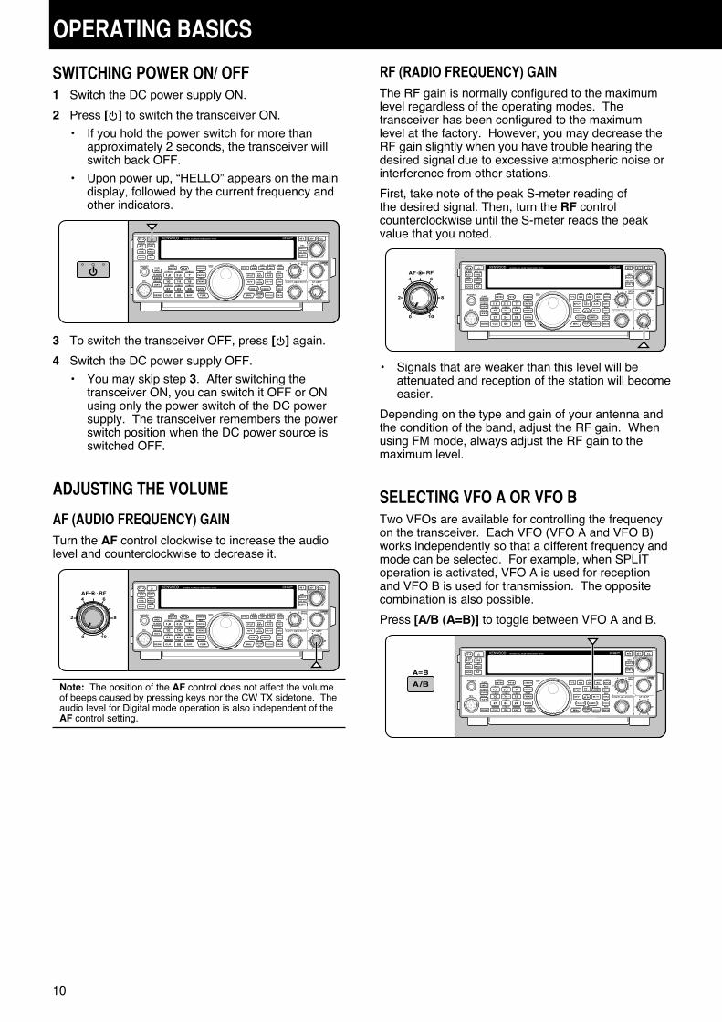
SWITCHING POWER ON/ OFF1 Switch the DC power supply ON.
2 Press [ ] to switch the transceiver ON.
• If you hold the power switch for more than approximately 2 seconds, the transceiver will switch back OFF.
• Upon power up, “HELLO” appears on the main display, followed by the current frequency and other indicators.
3 To switch the transceiver OFF, press [ ] again.
4 Switch the DC power supply OFF.
• You may skip step 3. After switching the transceiver ON, you can switch it OFF or ON using only the power switch of the DC power supply. The transceiver remembers the power switch position when the DC power source is switched OFF.
ADJUSTING THE VOLUME
AF (AUDIO FREQUENCY) GAINTurn the AF control clockwise to increase the audio level and counterclockwise to decrease it.
Note: The position of the AF control does not affect the volume of beeps caused by pressing keys nor the CW TX sidetone. The audio level for Digital mode operation is also independent of the AF control setting.
RF (RADIO FREQUENCY) GAINThe RF gain is normally configured to the maximum level regardless of the operating modes. The transceiver has been configured to the maximum level at the factory. However, you may decrease the RF gain slightly when you have trouble hearing the desired signal due to excessive atmospheric noise or interference from other stations.
First, take note of the peak S-meter reading of the desired signal. Then, turn the RF control counterclockwise until the S-meter reads the peak value that you noted.
• Signals that are weaker than this level will be attenuated and reception of the station will become easier.
Depending on the type and gain of your antenna and the condition of the band, adjust the RF gain. When using FM mode, always adjust the RF gain to the maximum level.
SELECTING VFO A OR VFO BTwo VFOs are available for controlling the frequency on the transceiver. Each VFO (VFO A and VFO B) works independently so that a different frequency and mode can be selected. For example, when SPLIT operation is activated, VFO A is used for reception and VFO B is used for transmission. The opposite combination is also possible.
Press [A/B (A=B)] to toggle between VFO A and B.

11
3 OPERATING BASICS
SELECTING A BANDPress [1.8 (1)] ~ [50 (0)] or [GENE] to select your desired band.
• Press each key to cycle through the 3 default settings as shown in the table below.
• Each setting can be modified with your personal preference for frequency and mode. After modifying the setting, pressing the key again will save that setting.
Key TypeFrequency
Range (MHz)
Default Setting (MHz)/ Mode
1 2 3
[1.8 (1)]K
1.62 ~ 2
1.8/ CW
1.82/ CW
1.84/ CW
E 1.83/ CW
1.84/ CW
1.81/ CW
[3.5 (2)]K
3 ~ 4 3.5/ LSB
3.7/ LSB
3.8/ LSB
E 3.79/ LSB
[7 (3)]K
6.5 ~ 7.5 7.0/ LSB
7.1/ LSB
7.2/ LSB
E 7.05/ LSB
7.1/ LSB
[10 (4)] All 10 ~ 10.5 10.1/ CW
10.12/ CW
10.14/ CW
[14 (5)] All 13.5 ~ 14.5 14.0/ USB
14.1/ USB
14.2/ USB
[18 (6)] All 18 ~ 19 18.068/ USB
18.11/ USB
18.15/ USB
[21 (7)] All 20.5 ~ 21.5 21.0/ USB
21.15/ USB
21.3/ USB
[24 (8)] All 24 ~ 25 24.89/ USB
24.93/ USB
24.95/ USB
[28 (9)] All 27.5 ~ 30 28/ USB
28.3/ USB
29/ FM
[50 (0)]K
50 ~ 54 50/ USB
50.125/ USB 51/
FME 50.15/
USB
[GENE]K
0.03 ~ 60 0.1357/ CW
5.3305/ USB 5.4035/
USBE 5.2585/
USB
SELECTING A MODEPress one of the following keys to select your desired mode set: [LSB/USB], [CW/FSK (REV)], or [FM/AM (FM-N)].
[LSB/USB]Press to select LSB or USB mode. Press again to toggle between LSB and USB mode.While in LSB mode, press [DATA] to toggle between LSB and LSB-DATA mode. Likewise, while in USB mode press [DATA] to toggle between USB and USB-DATA mode.Additionally, while in LSB-DATA or USB-DATA mode, you can press [LSB/USB] to toggle between LSB-DATA and USB-DATA mode.
[CW/FSK (REV)]Press to select CW or FSK mode. Press again to toggle between CW and FSK mode.While in CW mode, press and hold [CW/FSK (REV)] to toggle between CW and CW-R mode. Likewise, while in FSK mode press and hold [CW/FSK (REV] to toggle between FSK and FSK-R mode.Additionally, while in CW-R or FSK-R mode, you can press [CW/FSK (REV)] to toggle between CW-R and FSK-R mode.
[FM/AM (FM-N)]Press to select FM or AM mode. Press again to toggle between FM and AM mode.While in FM mode, press and hold [FM/AM (FM-N)] to toggle between FM and FM-NAR mode, or press [DATA] to toggle between FM and FM-DATA mode.Additionally, while in FM-NAR mode, press [DATA] to toggle between FM-NAR and FM-NAR-DATA mode and while in FM-DATA mode, press and hold [FM/AM (FM-N)] to toggle between FM-DATA and FM-NAR-DATA mode.
Access Menu No. 23 then press [M.IN] to select “on” to turn the Auto Mode selection ON. When it is ON, “ ” appears. As a default, if you change the frequency above or below 9.5 MHz, the transceiver automatically switches modes; LSB for frequencies under 9.5 MHz and USB for frequencies 9.5 MHz and over. You can further add the frequency borders to the Auto Mode selection {page 51}.

3 OPERATING BASICS
12
MULTI-FUNCTION METERThe multi-function meter measures the parameters in the table below. The S-meter and FILTER scales appears when the transceiver is in receive mode, and the PWR meter appears when it is in transmit mode. Each press of [METER (DRV)] cycles between the ALC, COMP, and SWR meters. Peak readings for the S-meter, ALC, SWR, COMP, and PWR functions are held momentarily.
ALC
COMP
SWR
Meter Name Parameters Measured
S Strength of received signals
PWR Transmission output power
ALC Automatic level control status
SWR Antenna system standing wave ratio
COMPSpeech compression level when using the Speech Processor {page 31}
FILTER IF filter width {page 38}
Note:◆ The COMP meter functions only when the Speech
Processor is ON for SSB, FM, or AM mode.◆ Peak Hold readings cannot be deactivated.◆ The S-meter responds differently in FM mode, compared to
other modes. This is not a malfunction.
ADJUSTING THE SQUELCHThe purpose of the Squelch is to mute the speaker when no signals are present. With the squelch level correctly set, you will hear sound only while actually receiving signals. The higher the selected squelch level, the stronger the signals must be to receive. The appropriate squelch level depends on the ambient RF noise conditions.
Turn the SQL control when there are no signals present to select the squelch level at which the background noise is just eliminated; the green TX-RX LED will turn off. Many ham operators prefer leaving the SQL control fully counterclockwise unless operating on a full-carrier mode such as FM. The squelch level for the transceiver is preset at the factory to approximately the 9 o’clock position for FM and 11 o’clock for SSB and AM.
TUNING A FREQUENCYTurn the Tuning control clockwise or press Mic [UP to increase the frequency. Turn the Tuning control counterclockwise or press Mic [DWN] to decrease the frequency.
You may prefer directly entering a frequency using the numeric keypad if the desired frequency is far from the current frequency. Press [ENT], then press the numeric keys as necessary. For details, refer to “Direct Frequency Entry” {page 28}.

3 OPERATING BASICS
13
TRANSMITTINGFor voice communications, press and hold Mic [PTT] and speak into the microphone in your normal voice. When you finish speaking, release Mic [PTT] to receive.
To transmit CW, press [VOX (REV)] to turn the Break-in function ON. “ ” appears. Close the key or keyer paddle. Connect a key or keyer paddle {page 2}, then select CW using [CW/FSK (REV)].
For a detailed explanation on transmitting, refer to “BASIC COMMUNICATIONS”, beginning on page 21.
SELECTING TRANSMISSION POWERIt is wise to select a lower transmission power if communication is still reliable. This lowers the risk of interfering with others on the band. When operating from battery power, selecting a lower transmission power allows you more operating time before recharging is necessary. This transceiver allows you to change the transmission power even while transmitting.
1 Press [PWR (TX MONI)].
• The current transmission power appears.
2 Turn the MULTI/CH control counterclockwise to reduce the power or clockwise to increase the power.
3 Press [PWR (TX MONI)] or [CLR] to complete the setting.
Note: You can access Menu No. 48, and select “on” to change the step size from 5 W to 1 W {page 56}.
MICROPHONE GAINThe microphone gain must be adjusted when SSB or AM mode is selected without using the speech processor {pages 21, 22}.
1 Press [MIC (CAR)].
• The current microphone gain level appears. The range is from 0 to 100 with a default of 50.
2 Press and hold Mic [PTT].
• The TX-RX LED lights red.
3 SSB: While speaking into the microphone, adjust the MULTI/CH control so that the ALC meter reflects your voice level but does not exceed the ALC limit.
AM: While speaking into the microphone, adjust the MULTI/CH control so that the power meter slightly reflects your voice level.
FM: Access Menu No. 47 and select “1” (Normal), “2” (Medium), or “3” (High) for the microphone gain if necessary {page 21}.
4 Release Mic [PTT] to receive.
• The TX-RX LED lights green or turns off, depending on the SQL control setting.
5 Press [MIC (CAR)] or [CLR] to exit the Microphone gain adjustment.
Note: When using the MC-90 microphone in FM mode, select “3” (High) for the microphone gain. The microphone sensitivity is low in FM mode. This may cause insufficient modulation. For other microphones, select either “1” (Normal) or “2” (Medium).

14
MENU SETUP
WHAT IS A MENU?Many functions on this transceiver are selected or configured via a software-controlled Menu, rather than through the physical controls of the transceiver. Once familiar with the Menu system, you will appreciate the versatility it offers. You can customize the various timings, settings, and programming functions on this transceiver to meet your needs without using many controls and switches.
MENU A/ MENU BThis transceiver has 2 menus: Menu A and Menu B. These menus contain identical functions and can be configured independently. The transceiver, therefore, allows you to switch between 2 different environments quickly and easily. For example, you can configure Menu A for DXing and contesting while Menu B is for relaxed local ragchewing. By switching from Menu A to Menu B, you can instantly change the Menu configuration and key assignment to suit your current operating style. Or, 2 operators may share a single transceiver by dedicating one Menu to each operator. Both operators can always enjoy their own configuration.
MENU ACCESS1 Press [MENU].
• The Menu No. and setting appear on the display, and the explanation of the menu appears on the sub-display.
2 Press [A/B (A=B)] to select Menu A or B.
• “ ” or “ ” appears, indicating which Menu is selected.
3 Press [Q-M.IN]/ [Q-MR] or turn the MULTI/CH control to select the desired Menu No.
• Each time you change the Menu No., a different scrolling message appears on the sub-display, describing the Menu No.
4 Press [M.IN]/ [SCAN (SG.SEL)], or Mic [UP]/ [DWN] to select a parameter.
5 Press [MENU] to exit Menu mode.
QUICK MENUBecause the number of functions this transceiver provides is extraordinary, there are numerous items in each Menu. If you find accessing desired Menu Nos. to be too time consuming, use the Quick Menu to create your own customized, abbreviated Menu. You can then add those Menu Nos. which you frequently use, to the Quick Menu. Copying Menu Nos. to the Quick Menu has no effect on the Menu.
PROGRAMMING THE QUICK MENU1 Press [MENU].
2 Press [Q-M.IN]/ [Q-MR] or turn the MULTI/CH control to select the desired Menu No.
3 Press [FINE (F.LOCK)].
• “ ” appears, indicating that the Menu item has been added to the Quick Menu.
• To remove the item from the Quick Menu, press [FINE (F.LOCK)] again. “ ” disappears.
4 Press [MENU] to exit Menu mode.
USING THE QUICK MENU1 Press [MENU].
2 Press [MHz].
• “ ” appears.
3 Press [Q-M.IN]/ [Q-MR] or turn the MULTI/CH control to select the desired Quick Menu No.
4 Press [M.IN]/ [SCAN (SG.SEL)], or Mic [UP]/ [DWN] to change the current setting for the selected Menu No.
• When the Menu is registered to the Quick Menu list, “ ” appears.
5 Press [MENU] to exit Quick Menu mode.Note: If the Quick Menu has not been programmed, Press [Q-M.IN]/[Q-MR] or turning the MULTI/CH control in step 2 causes “CHECK” to be output in Morse code.
15
4 MENU SETUP
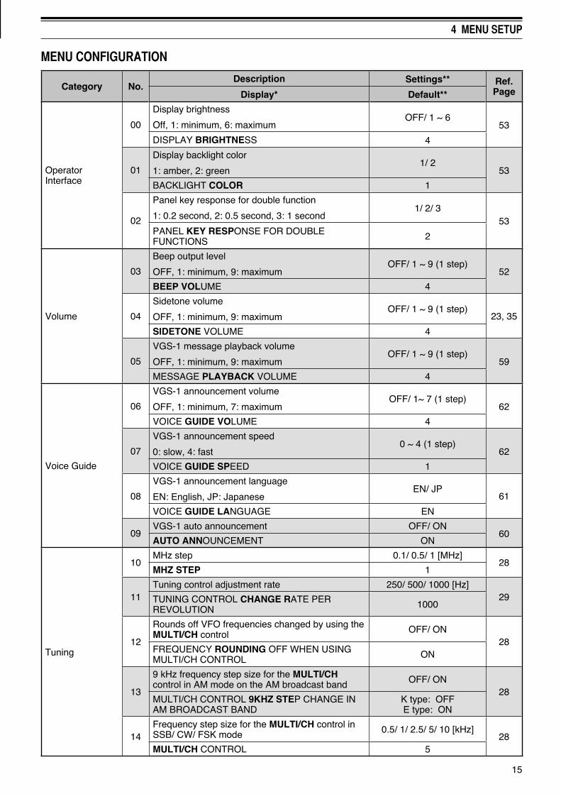
MENU CONFIGURATION
Category No.Description Settings** Ref.
PageDisplay* Default**
Operator Interface
00
Display brightness
Off, 1: minimum, 6: maximumOFF/ 1 ~ 6
53
DISPLAY BRIGHTNESS 4
01
Display backlight color
1: amber, 2: green1/ 2
53
BACKLIGHT COLOR 1
02
Panel key response for double function
1: 0.2 second, 2: 0.5 second, 3: 1 second1/ 2/ 3
53PANEL KEY RESPONSE FOR DOUBLE FUNCTIONS 2
Volume
03
Beep output level
OFF, 1: minimum, 9: maximumOFF/ 1 ~ 9 (1 step)
52
BEEP VOLUME 4
04
Sidetone volume
OFF, 1: minimum, 9: maximumOFF/ 1 ~ 9 (1 step)
23, 35
SIDETONE VOLUME 4
05
VGS-1 message playback volume
OFF, 1: minimum, 9: maximumOFF/ 1 ~ 9 (1 step)
59
MESSAGE PLAYBACK VOLUME 4
Voice Guide
06
VGS-1 announcement volume
OFF, 1: minimum, 7: maximumOFF/ 1~ 7 (1 step)
62
VOICE GUIDE VOLUME 4
07
VGS-1 announcement speed
0: slow, 4: fast0 ~ 4 (1 step)
62
VOICE GUIDE SPEED 1
08
VGS-1 announcement language
EN: English, JP: JapaneseEN/ JP
61
VOICE GUIDE LANGUAGE EN
09VGS-1 auto announcement OFF/ ON
60AUTO ANNOUNCEMENT ON
Tuning
10MHz step 0.1/ 0.5/ 1 [MHz]
28MHZ STEP 1
11Tuning control adjustment rate 250/ 500/ 1000 [Hz]
29TUNING CONTROL CHANGE RATE PER REVOLUTION 1000
12
Rounds off VFO frequencies changed by using the MULTI/CH control OFF/ ON
28FREQUENCY ROUNDING OFF WHEN USING MULTI/CH CONTROL ON
13
9 kHz frequency step size for the MULTI/CH control in AM mode on the AM broadcast band OFF/ ON
28MULTI/CH CONTROL 9KHZ STEP CHANGE IN AM BROADCAST BAND
K type: OFFE type: ON
14Frequency step size for the MULTI/CH control in SSB/ CW/ FSK mode 0.5/ 1/ 2.5/ 5/ 10 [kHz]
28MULTI/CH CONTROL 5
16
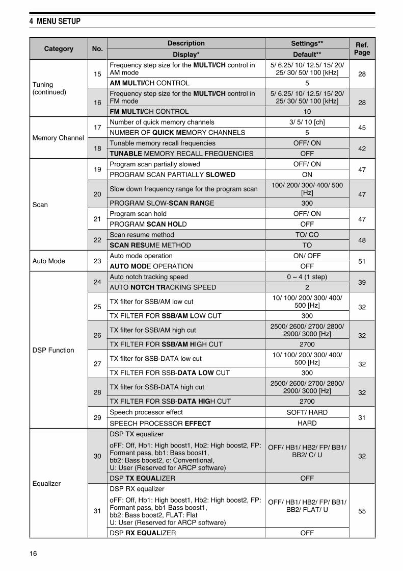
4 MENU SETUP
Category No.Description Settings** Ref.
PageDisplay* Default**
Tuning (continued)
15Frequency step size for the MULTI/CH control in AM mode
5/ 6.25/ 10/ 12.5/ 15/ 20/ 25/ 30/ 50/ 100 [kHz] 28
AM MULTI/CH CONTROL 5
16Frequency step size for the MULTI/CH control in FM mode
5/ 6.25/ 10/ 12.5/ 15/ 20/ 25/ 30/ 50/ 100 [kHz] 28
FM MULTI/CH CONTROL 10
Memory Channel
17Number of quick memory channels 3/ 5/ 10 [ch]
45NUMBER OF QUICK MEMORY CHANNELS 5
18Tunable memory recall frequencies OFF/ ON
42TUNABLE MEMORY RECALL FREQUENCIES OFF
Scan
19Program scan partially slowed OFF/ ON
47PROGRAM SCAN PARTIALLY SLOWED ON
20Slow down frequency range for the program scan 100/ 200/ 300/ 400/ 500
[Hz] 47PROGRAM SLOW-SCAN RANGE 300
21Program scan hold OFF/ ON
47PROGRAM SCAN HOLD OFF
22Scan resume method TO/ CO
48SCAN RESUME METHOD TO
Auto Mode 23Auto mode operation ON/ OFF
51AUTO MODE OPERATION OFF
DSP Function
24Auto notch tracking speed 0 ~ 4 (1 step)
39AUTO NOTCH TRACKING SPEED 2
25TX filter for SSB/AM low cut 10/ 100/ 200/ 300/ 400/
500 [Hz] 32TX FILTER FOR SSB/AM LOW CUT 300
26TX filter for SSB/AM high cut 2500/ 2600/ 2700/ 2800/
2900/ 3000 [Hz] 32TX FILTER FOR SSB/AM HIGH CUT 2700
27TX filter for SSB-DATA low cut 10/ 100/ 200/ 300/ 400/
500 [Hz] 32TX FILTER FOR SSB-DATA LOW CUT 300
28TX filter for SSB-DATA high cut 2500/ 2600/ 2700/ 2800/
2900/ 3000 [Hz] 32TX FILTER FOR SSB-DATA HIGH CUT 2700
29Speech processor effect SOFT/ HARD
31SPEECH PROCESSOR EFFECT HARD
Equalizer
30
DSP TX equalizer
oFF: Off, Hb1: High boost1, Hb2: High boost2, FP: Formant pass, bb1: Bass boost1, bb2: Bass boost2, c: Conventional, U: User (Reserved for ARCP software)
OFF/ HB1/ HB2/ FP/ BB1/ BB2/ C/ U 32
DSP TX EQUALIZER OFF
31
DSP RX equalizer
oFF: Off, Hb1: High boost1, Hb2: High boost2, FP: Formant pass, bb1 Bass boost1, bb2: Bass boost2, FLAT: FlatU: User (Reserved for ARCP software)
OFF/ HB1/ HB2/ FP/ BB1/ BB2/ FLAT/ U 55
DSP RX EQUALIZER OFF
17
4 MENU SETUP
Category No.Description Settings** Ref.
PageDisplay* Default**
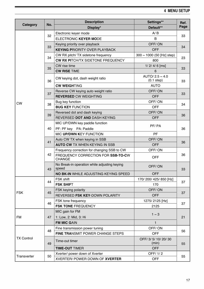
CW
32Electronic keyer mode A/ B
33ELECTRONIC KEYER MODE B
33Keying priority over playback OFF/ ON
34KEYING PRIORITY OVER PLAYBACK OFF
34CW RX pitch/ TX sidetone frequency 300 ~ 1000 (50 [Hz] step)
23CW RX PITCH/TX SIDETONE FREQUENCY 800
35CW rise time 1/ 2/ 4/ 6 [ms]
33CW RISE TIME 6
36CW keying dot, dash weight ratio AUTO/ 2.5 ~ 4.0
(0.1 step) 33CW WEIGHTING AUTO
37Reverse CW keying auto weight ratio OFF/ ON
33REVERSED CW WEIGHTING OFF
38Bug key function OFF/ ON
34BUG KEY FUNCTION OFF
39Reversed dot and dash keying OFF/ ON
36REVERSED DOT AND DASH KEYING OFF
40
MIC UP/DWN key paddle function
PF: PF key PA: PaddlePF/ PA
36
MIC UP/DWN KEY FUNCTION PF
41Auto CW TX when keying in SSB OFF/ ON
36AUTO CW TX WHEN KEYING IN SSB OFF
42Frequency correction for changing SSB to CW OFF/ ON
36FREQUENCY CORRECTION FOR SSB-TO-CW CHANGE OFF
43No Break-in operation while adjusting keying speed OFF/ ON
33NO BK-IN WHILE ADJUSTING KEYING SPEED OFF
FSK
44FSK shift 170/ 200/ 425/ 850 [Hz]
37FSK SHIFT 170
45FSK keying polarity OFF/ ON
37REVERSED FSK KEY-DOWN POLARITY OFF
46FSK tone frequency 1275/ 2125 [Hz]
37FSK TONE FREQUENCY 2125
FM 47
MIC gain for FM
1: Low, 2: Mid, 3: Hi1 ~ 3
21
FM MIC GAIN 1
TX Control
48Fine transmission power tuning OFF/ ON
56FINE TRANSMIT POWER CHANGE STEPS OFF
49Time-out timer OFF/ 3/ 5/ 10/ 20/ 30
(min) 55TIME-OUT TIMER OFF
Transverter 50Xverter/ power down of Xverter OFF/ 1/ 2
55XVERTER/ POWER DOWN OF XVERTER OFF

18
4 MENU SETUP
Category No.Description Settings** Ref.
PageDisplay* Default**
Antenna Tuner
51TX hold when AT completes the tuning OFF/ ON
50ANTENNA TUNER TX HOLD OFF
52In-line AT while receiving OFF/ ON
50ANTENNA TUNER FOR RECEPTION OFF
Linear Amp
53Linear amplifier control relay for HF band OFF/ 1/ 2/ 3
53HF LINEAR AMPLIFIER CONTROL RELAY OFF
54Linear amplifier control relay for 50 MHz band OFF/ 1/ 2/ 3
5350MHZ LINEAR AMPLIFIER CONTROL RELAY OFF
Message
55Constant recording OFF/ ON
60CONSTANT RECORDING ON
56Repeat the playback OFF/ ON
36, 59PLAYBACK REPEAT OFF
57Interval time for repeating the playback 0 ~ 60 [s] (1 step)
36, 59PLAYBACK INTERVAL TIME 10
Split/ Transfer
58Split frequency transfer in master/ slave operation OFF/ ON
57TRANSFER SPLIT FREQUENCY DATA TO ANOTHER TRANSCEIVER OFF
59Permit to write the transferred Split frequencies to the target VFOs OFF/ ON
57COPY SPLIT FREQUENCY DATA TO VFO OFF
TX Inhibit 60TX inhibit OFF/ ON
32TX INHIBIT OFF
PC (Communication)
61COM port communication speed***
4800/ 9600/ 19200/ 38400/ 57600/ 115200 57
COM PORT BAUDRATE 9600 (bps)
62USB port communication speed***
4800/ 9600/ 19200/ 38400/ 57600/ 115200 57
USB PORT BAUDRATE 115200 (bps)
External Audio (Input/ Output)
63Audio input line selection for data communications ACC2/ USB
58AUDIO INPUT LINE SELECT FOR DATA COMMUNICATIONS
ACC2
64Audio level of USB input for data communications 0 ~ 9 (1 step)
58AUDIO LEVEL OF USB INPUT FOR DATA COMMUNICATIONS
4
65Audio level of USB output for data communications 0 ~ 9 (1 step)
58AUDIO LEVEL OF USB OUTPUT FOR DATA COMMUNICATIONS
4
66Audio level of ACC2 input for data communications 0 ~ 9 (1 step)
58AUDIO LEVEL OF ACC2 INPUT FOR DATA COMMUNICATIONS
4
67
AUDIO level of ACC2 output for data communications
0 ~ 9 (1 step)58
AUDIO LEVEL OF ACC2 OUTPUT FOR DATA COMMUNICATIONS
4
68Mixing beep tones for ACC2/USB audio output OFF/ ON
58MIXING BEEP TONES FOR ACC2/USB AUDIO OUTPUT
OFF
19
4 MENU SETUP
Category No.Description Settings** Ref.
PageDisplay* Default**
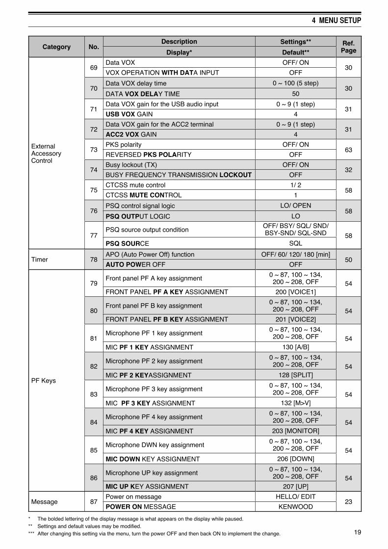
External Accessory Control
69Data VOX OFF/ ON
30VOX OPERATION WITH DATA INPUT OFF
70Data VOX delay time 0 ~ 100 (5 step)
30DATA VOX DELAY TIME 50
71Data VOX gain for the USB audio input 0 ~ 9 (1 step)
31USB VOX GAIN 4
72Data VOX gain for the ACC2 terminal 0 ~ 9 (1 step)
31ACC2 VOX GAIN 4
73PKS polarity OFF/ ON
63REVERSED PKS POLARITY OFF
74Busy lockout (TX) OFF/ ON
32BUSY FREQUENCY TRANSMISSION LOCKOUT OFF
75CTCSS mute control 1/ 2
58CTCSS MUTE CONTROL 1
76PSQ control signal logic LO/ OPEN
58PSQ OUTPUT LOGIC LO
77PSQ source output condition
OFF/ BSY/ SQL/ SND/ BSY-SND/ SQL-SND 58
PSQ SOURCE SQL
Timer 78APO (Auto Power Off) function OFF/ 60/ 120/ 180 [min]
50AUTO POWER OFF OFF
PF Keys
79Front panel PF A key assignment 0 ~ 87, 100 ~ 134,
200 ~ 208, OFF 54FRONT PANEL PF A KEY ASSIGNMENT 200 [VOICE1]
80Front panel PF B key assignment 0 ~ 87, 100 ~ 134,
200 ~ 208, OFF 54FRONT PANEL PF B KEY ASSIGNMENT 201 [VOICE2]
81Microphone PF 1 key assignment 0 ~ 87, 100 ~ 134,
200 ~ 208, OFF 54MIC PF 1 KEY ASSIGNMENT 130 [A/B]
82Microphone PF 2 key assignment 0 ~ 87, 100 ~ 134,
200 ~ 208, OFF 54MIC PF 2 KEYASSIGNMENT 128 [SPLIT]
83Microphone PF 3 key assignment 0 ~ 87, 100 ~ 134,
200 ~ 208, OFF 54MIC PF 3 KEY ASSIGNMENT 132 [M>V]
84Microphone PF 4 key assignment 0 ~ 87, 100 ~ 134,
200 ~ 208, OFF 54MIC PF 4 KEY ASSIGNMENT 203 [MONITOR]
85Microphone DWN key assignment 0 ~ 87, 100 ~ 134,
200 ~ 208, OFF 54MIC DOWN KEY ASSIGNMENT 206 [DOWN]
86Microphone UP key assignment 0 ~ 87, 100 ~ 134,
200 ~ 208, OFF 54MIC UP KEY ASSIGNMENT 207 [UP]
Message 87Power on message HELLO/ EDIT
23POWER ON MESSAGE KENWOOD
* The bolded lettering of the display message is what appears on the display while paused.** Settings and default values may be modified.*** After changing this setting via the menu, turn the power OFF and then back ON to implement the change.
20
4 MENU SETUP
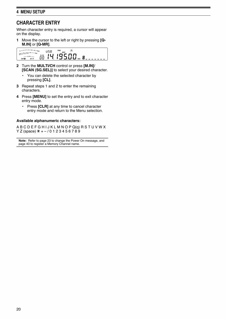
CHARACTER ENTRYWhen character entry is required, a cursor will appear on the display.
1 Move the cursor to the left or right by pressing [Q-M.IN] or [Q-MR].
2 Turn the MULTI/CH control or press [M.IN]/ [SCAN (SG.SEL)] to select your desired character.
• You can delete the selected character by pressing [CL].
3 Repeat steps 1 and 2 to enter the remaining characters.
4 Press [MENU] to set the entry and to exit character entry mode.
• Press [CLR] at any time to cancel character entry mode and return to the Menu selection.
Available alphanumeric characters:
A B C D E F G H I J K L M N O P Q(q) R S T U V W X Y Z (space) + – / 0 1 2 3 4 5 6 7 8 9
Note: Refer to page 23 to change the Power On message, and page 43 to register a Memory Channel name.

21
BASIC COMMUNICATIONS
SSB TRANSMISSIONSSB is the most commonly-used mode on the HF Amateur radio bands. Compared with other voice modes, SSB requires only a narrow bandwidth for communications. SSB also allows long distance communications with minimum transmission power.
If necessary, refer to “OPERATING BASICS”, beginning on page 10, for details on how to receive.
1 Select an operating frequency.
2 Press [LSB/USB] until “USB” or “LSB” appears on the operating mode display.
• If the desired sideband (“USB” or “LSB”) does not appear, select the other sideband first. Then, press [LSB/USB]. The mode indicator changes to your desired sideband.
• “USB” represents the upper sideband and “LSB” represents the lower sideband. Normally, USB is used for the communications for 10 MHz and above while LSB is used for the frequencies below 10 MHz.
3 Press [MIC (CAR)] to adjust the Microphone gain.
• The current gain level appears on the sub-display.
4 Press and hold Mic [PTT].
• The TX-RX LED lights red.
• Refer to “VOX” {page 30} for information on automatic TX/ RX switching.
5 Speak into the microphone and turn the MULTI/CH control so that the ALC meter reflects your voice level but does not exceed the ALC limit.
• Speak in your normal tone and level of voice. Speaking too close to the microphone or too loudly may increase distortion and reduce intelligibility at the receiving end.
• You may want to use the Speech Processor. Refer to “SPEECH PROCESSOR” {page 31} for details.
6 Release Mic [PTT] to return to Reception mode.
• The TX-RX LED lights green or turns off, depending on the SQL control position.
7 Press [MIC (CAR)] or [CLR] to exit the Microphone gain adjustment.
Refer to “COMMUNICATING AIDS”, beginning on page 28, for information on additional useful operation functions.
FM TRANSMISSIONFM is a common mode for communicating on VHF or UHF frequencies. As for HF and the 6 m band, 29 MHz and 51-54 MHz bands are commonly used for FM operation. You can also utilize 10 m/ 6 m band repeaters to reach your friends when they are outside or skipped over from your coverage. Although FM requires a wider bandwidth when compared to SSB or AM mode, it has the finest audio quality among these modes. When combined with the full-quieting aspect of FM signals, which suppresses background noise on the frequency, FM can be the best method for maintaining casual communications with your local friends.
If necessary, refer to “OPERATING BASICS”, beginning on page 10, for details on how to receive.
1 Select an operating frequency.
2 Press [FM/AM (FM-N)] until “FM” appears.
• If “FM” does not appear, select “AM”, then press [FM/AM (FM-N)]. The mode indicator changes to “FM”.
3 Press and hold Mic [PTT].
• The TX-RX LED lights red.
• Refer to “VOX” {page 30} for information on automatic TX/ RX switching.
4 Speak into the microphone in your normal voice.
• Speaking too close to the microphone or too loudly may increase distortion and reduce intelligibility at the receiving end.
• You can switch the Microphone gain for FM between 1 (Normal), 2 (Medium), and 3 (High) by using Menu No. 47. 1 (Normal) is usually appropriate; however, select 3 (High) if other stations report that your modulation is weak.
5 Release Mic [PTT] to return to Reception mode.
• The TX-RX LED lights green or turns off, depending on the SQL control position.
Refer to “COMMUNICATING AIDS”, beginning on page 28, for additional information on useful operation functions.
Note: Microphone gain adjustment for SSB or AM has no effect in FM mode. In FM mode, you must select 1 (Normal), 2 (Medium), or 3 (High) in Menu No. 47.

5 BASIC COMMUNICATIONS
22
AM TRANSMISSIONEach mode used on the HF Amateur bands has its own advantages. Although long distance DX contacts may be less common while using AM, the superior audio quality characteristic of AM operation is one reason why some hams prefer this mode.
If necessary, refer to “OPERATING BASICS”, beginning on page 10, for details on how to receive.
1 Select an operating frequency.
2 Press [FM/AM (FM-N)] until “AM” appears.
• If “AM” does not appear, select “FM” first, then press [FM/AM (FM-N)]. The mode indicator changes to “AM”.
3 Press [MIC (CAR)] to enter the Microphone gain adjustment mode.
• The current gain level appears on the sub-display.
4 Press and hold Mic [PTT].
• The TX-RX LED lights red.
• Refer to “VOX” {page 30} for information on automatic TX/ RX switching.
5 Speak into the microphone and adjust the MULTI/CH control so that the power meter slightly reflects your voice level.
• Speak in your normal tone and level of voice. Speaking too close to the microphone or too loudly may increase distortion and reduce intelligibility at the receiving end.
• You may want to use the Speech Processor. Refer to “SPEECH PROCESSOR” {page 31} for details.
6 Release Mic [PTT] to return to Reception mode.
• The TX-RX LED lights green or turns off, depending on the SQL control position.
7 Press [MIC (CAR)] or [CLR] to exit the Microphone gain adjustment mode.
Refer to “COMMUNICATING AIDS”, beginning on page 28, for information on additional useful operation functions.
Note: When the TX power meter reading exceeds the value that you specified in the TX Power setting {page 56}, decrease the microphone gain or adjust your tone and level of voice.
NARROW BANDWIDTH FOR FMSelect wide band or narrow band TX deviation depending on whether the other station is using wide band or narrow band filter for FM mode. While “NAR” appears, the TS-590S transceiver transmits signals in narrow band FM but the reception IF filter bandwidth remains unchanged (Wide). The deviation selection is crucial to avoid audio distortion or insufficient intelligibility that the other station will encounter.
1 Press [FM/AM (FM-N)] until “FM” appears.
• If “FM” does not appear, select “AM” first, then press [FM/AM (FM-N)]. The mode indicator changes to “FM”.
2 Press and hold [FM/AM (FM-N)] to toggle the selection between wide and narrow TX deviation.
• “ ” appears when narrow TX deviation is selected.
CW TRANSMISSIONCW operators know that this mode is very reliable when communicating under worst conditions. It may be true that newer digital modes rival CW as being equally as useful in poor conditions. These modes, however, do not have the long history of service nor the simplicity that CW provides.
This transceiver has a built-in electronic keyer that supports a variety of functions. For details on using these functions, refer to “ELECTRONIC KEYER” {page 33}.
If necessary, refer to “OPERATING BASICS”, beginning on page 10, for details on how to receive.
1 Select the operating frequency.
2 Press [CW/FSK (REV)] until “CW” appears.
• If “CW” does not appear, select “FSK” first, then press [CW/FSK (REV)]. The mode indicator changes to “CW”.
• To precisely tune in another station, use Auto Zero-beat. Refer to “AUTO ZERO-BEAT” {page 23}.
3 Press [SEND].
• The TX-RX LED lights red.
4 Operate the Keys or Paddle.
• As you transmit, you should hear a sidetone that lets you monitor your own transmission.
5 Press [SEND] to return to Reception mode.
• The TX-RX LED lights green or turns off, depending on the SQL control setting.

23
5 BASIC COMMUNICATIONS
AUTO ZERO-BEATUse Auto Zero-beat before transmitting to tune in a CW station. Auto Zero-beat automatically and exactly matches your transmit frequency with the station you are receiving. Neglecting to do this will reduce your chances of being heard by the other station.
1 Tune to the CW signal using the Tuning control.
2 Press [CW T. (AGC OFF)] to start Auto Zero-beat while CW is selected for the operating mode.
• “CW TUNE” appears.
• Your reception frequency automatically changes so that the pitch (tone) of the received signal exactly matches the TX sidetone/ RX pitch frequency that you have selected. Refer to “TX SIDETONE/ RX PITCH FREQUENCY” {below}.
• When matching is completed, “CW TUNE” disappears.
• If matching is unsuccessful, the previous frequency is restored.
3 To quit Auto Zero-beat, press [CW T. (AGC OFF)] or [CLR].
Note:◆ When using Auto Zero-beat, the matching error is normally
within ±5 Hz.◆ Auto Zero-beat may fail if the keying speed of the target
station is too slow or if some interference is present.◆ When the RIT function is ON, only RIT frequencies change
to make the Auto Zero-beat adjustment.
TX SIDETONE/ RX PITCH FREQUENCYAs you send CW, you will hear tones from the transceiver speaker. These are called TX (transmission) sidetones. Listening to these tones, you can monitor what you are transmitting. You may also use the tones to ensure that your key contacts are closing, the keyer is functioning, or to practice sending without actually putting a signal on the air.
RX (reception) pitch refers to the frequency of CW that you hear after tuning in a CW station.
On this transceiver, the frequency of the sidetone and RX pitch are equal and selectable. Access Menu No. 34 to select the frequency that is most comfortable for you. The selectable range is from 300 Hz to 1000 Hz in steps of 50 Hz (default is 800 Hz).
To change the volume of the TX sidetone, access Menu No. 4. The selections range from 1 to 9 and OFF (default is 5).
Note:◆ The position of the AF control does not affect the volume of
the TX sidetone.◆ When changing the CW pitch/ side tone, the shift amount
of the receive filter is automatically applied to the CW pitch/ side tone. (In Quick Memory mode, the CW pitch/ side tone is not revised since the receive filter information stored in the Quick Memory has priority.)
CARRIER LEVELWhen using AM, CW, or FSK mode, you can adjust the carrier level.
1 Press and hold [MIC (CAR].
• The current gain level appears on the sub display.
2 Turn the MULTI/CH control so that the ALC meter reads within the limits of the ALC zone.
• For AM mode, adjust the MULTI/CH control so that the ALC meter just begins to indicate.
3 Press and hold [MIC (CAR] again or press [CLR] to complete the setting.
POWER ON MESSAGEEach time you switch the transceiver ON, “KENWOOD” (default) appears on the sub display for approximately 2 seconds. You can program your favorite message in place of the default message. You can enter a message using up to 8 characters.
1 Press [MENU], then press [Q-M.IN]/ [Q-MR] or turn the MULTI/CH control to access Menu No 87.
2 Press [M.IN]/ [SCAN (SG.SEL)] to begin editing the message.
3 Move the cursor to the left or right by pressing [Q-M.IN] or [Q-MR].
4 Press [M.IN]/ [SCAN (SG.SEL)] or turn the MULTI/CH control to select your desired character.
• You can delete the selected character by pressing [CL].
5 Repeat steps 3 and 4 to enter the remaining characters.
6 Press [MENU] to set the entry and exit character entry mode.
• Press [CLR] at any time to cancel character entry mode and exit the Menu mode.

ENHANCED COMMUNICATIONS
24
SPLIT-FREQUENCY OPERATIONUsually you can communicate with other stations using a single frequency for receiving and transmitting. In this case, you select only one frequency on either VFO A or VFO B. However, there are cases where you must select one frequency for receiving and a different frequency for transmitting. This requires the use of 2 VFOs. This is referred to as “split-frequency operation”. One typical case which requires this type of operation is when you use an FM repeater {page 25}. Another typical case is when you call a rare DX station.
When a rare or desirable DX station is heard, that operator may immediately get many simultaneous responses. Often, such a station is lost under the noise and confusion of many calling stations. If you find that you are suddenly being called by many operators, it is your responsibility to control the situation. You may announce that you will be “listening up 5 (kHz, from your present transmission frequency)”, or “listening down between 5 and 10 (kHz)”.
1 Press [A/B (A=B)] to select VFO A or VFO B.
• “ ” or “ ” appears to show which VFO is selected.
2 Select an operating frequency.
• This frequency will be used for transmission.
• To copy the selected VFO frequency to the other VFO, press and hold [A/B (A=B)].
3 Press [A/B (A=B)] to select the other VFO.
4 Select an operating frequency.
• This frequency will be used for reception.
5 Press [SPLIT].
• “ ” appears.
• Each time you press [A/B (A=B)], the reception and transmission frequencies are swapped.
6 To quit split-frequency operation, press [SPLIT] again.
• “ ” disappears.
TF-SET (TRANSMISSION FREQUENCY SET)TF-SET allows you to temporarily switch your transmission frequency and reception frequency. Canceling this function immediately restores the original transmission and reception frequencies. By activating TF-SET, you can listen on your transmit frequency, and change it while listening. This allows you to check whether or not the newly selected transmission frequency is free of interference.
1 Configure split-frequency operation as explained in the previous section.
2 Press and hold [TF-SET], then turn the Tuning control or press Mic [UP]/ [DWN] to change the transmission frequency.
• The transceiver receives on the frequency as you change, but the frequency shown on the sub-display (the original reception frequency) stays unchanged.
3 Release [TF-SET].
• You are now receiving again on your original reception frequency.
Successfully contacting a DX station in a pileup often depends on making a well-timed call on a clear frequency. That is, it is important to select a relatively clear transmission frequency and to transmit at the exact instant when the DX station is listening but the majority of the groups aren’t transmitting. Switch your reception and transmission frequencies by using the TF-SET function and listen to your transmission frequency. You will soon learn the rhythm of the DX station and the pileup. The more proficient you become at using this function, the more DX stations you will contact.
Note:◆ TF-SET is disabled while transmitting.◆ You can change the transmission frequency even when the
Frequency lock function is ON.◆ An RIT offset frequency is not added; however, an XIT offset
frequency is added to the transmit frequency during TF-SET.

25
6 ENHANCED COMMUNICATIONS
FM REPEATER OPERATIONMost Amateur radio voice repeaters use a separate reception and transmission frequency. The transmission frequency may be higher or lower than the reception frequency. In addition, some repeaters may require the transceiver to transmit a subtone before the repeater can be used.
Compared to simplex communication, you can usually transmit over much greater distances by using a repeater. Repeaters are typically located on a mountain top or other elevated location. Often they operate at higher ERP (Effective Radiated Power) than a typical station. This combination of elevation and high ERP allows communications over considerable distances.
HF/ 6 m band repeaters usually operate in the 29 MHz FM sub-band and 51-54 MHz band. This special service combines the advantages of FM operation, good fidelity with noise and interference immunity, with the excitement of HF DX (long distance) communications. Even on a quiet day, 10 m FM provides reliable around-town communications with the potential for sudden DX from across the country or around the world.
Note:◆ When programming 2 separate frequencies using 2 VFOs,
be sure to select FM mode on both VFOs.◆ When operating through a repeater, over deviation caused
by speaking too loudly into the microphone can cause your signal to “talk-off” (break up) through the repeater.
29.520 MHz88.5 Hz
29.520 MHz88.5 Hz
29.620 MHz
29.620 MHz
1 Press [A/B (A=B)] to select VFO A or VFO B.
• “ ” or “ ” appears to show which VFO is selected.
2 Turn the Tuning control or the MULTI/CH control to select the reception frequency.
3 Press [FM/AM (FM-N)] to select FM mode.
4 Press and hold [A/B (A=B)] to duplicate the frequencies and other data to the other VFO.
5 Turn the Tuning control or the MULTI/CH control to select the transmission frequency.
6 Press [AGC/T (SEL] to turn the Tone function ON if the repeater requires a subtone.
• “ ” appears.
• Refer to “Selecting a Tone Frequency” for more details on the subtone {page 26}.
• To quit the Subtone function, press [AGC/T (SEL)] twice.
7 Press [SPLIT].
• “ ” appears.
8 Press [A/B (A=B)] to return to the original reception frequency.
9 Press Mic [PTT] to transmit.
• The VFO changes to the other VFO to transmit.
• Each time you press [A/B (A=B)], the reception and transmission frequencies are swapped.
10 Press [SPLIT] to quit split-frequency operation.
• “ ” disappears.
The data that you select in steps 1 to 8 can be stored in memory. Refer to “Split-Frequency Channels” {page 41}.
Note:◆ When operating through a repeater, over deviation caused
by speaking too loudly into the microphone can cause your signal to “talk-off” (break up) through the repeater.
◆ To check the tone frequency stored in a memory channel, recall the desired memory channel and press [AGC/T (SEL)].
TRANSMITTING A TONEIn general, FM repeaters require the transceiver to transmit a sub-audible tone to prevent other repeaters on the same frequency from locking each other up. The required tone frequency differs among repeaters. Repeaters also differ in their requirements for either continuous or burst tones. For the appropriate selections for your accessible repeaters, consult your local repeater reference.
After completing the tone settings, pressing and holding Mic [PTT] causes the transceiver to transmit the selected tone. If you have selected a 1750 Hz tone, the transceiver sends a 500 ms tone burst each time transmission starts.
Note: If you store tone settings in a memory channel, you need not reprogram each time. Refer to “MEMORY FEATURES” {page 41}.

26
6 ENHANCED COMMUNICATIONS
TONE FREQUENCY ID SCANThis function scans through all tone frequencies to identify the incoming tone frequency on a received signal. You may find this useful when you do not know the tone frequency that the repeater uses.
1 While the Tone function is ON (“ ” is visible), press and hold [AGC/T (SEL)].
• The current tone frequency appears.
2 Press [SCAN (SG.SEL)] to activate the Tone frequency ID scan.
• While the transceiver is receiving a signal, “ ” blinks and every tone frequency is scanned. When the tone frequency is identified, the transceiver stops scanning and the identified frequency is displayed.
• Press [SCAN (SG.SEL)] or [CLR] to stop scanning while the tone frequency ID scan is active.
• Press [SCAN (SG.SEL)] again to resume scanning.
Note: Received signals are audible while scanning is in progress.
FM CTCSS OPERATIONYou may sometimes want to hear calls only from specific persons. When using FM mode, the Continuous Tone Coded Squelch System (CTCSS) allows you to ignore (not hear) unwanted calls from other persons who are using the same frequency. A CTCSS tone is sub-audible and is selectable from among the 42 tone frequencies. Select the same CTCSS tone as the other stations in your group. You will not hear calls from stations other than those using the same CTCSS tone.
Note: CTCSS does not cause your conversation to be private. It only relieves you from listening to unwanted conversations.
1 Press [A/B (A=B)] to select VFO A or VFO B.
• “ ” or “ ” appears to show which VFO is selected.
2 Select the 29 MHz band or the 51-54 MHz band using [28 (9)] or [50 (0)].
3 Select the desired frequency with the Tuning control or MULTI/CH control.
4 Press [FM/AM (FM-N)] to select FM mode.
5 Turn the SQL control to adjust the squelch.
6 Press [AGC/T (SEL)] until “ ” appears.
7 While “ ” is visible, press and hold [AGC/T (SEL)].
• The current CTCSS frequency appears (default is 88.5 Hz).
■ Activating the Tone Function
1 Confirm that FM mode has been selected on the VFO(s) {page 10}.
• When using 2 VFOs, you must select FM mode on both VFOs.
2 Press [AGC/T (SEL)].
• “ ” appears.
Note: You cannot use the Tone function with the CTCSS function.
■ Selecting a Tone Frequency
1 While “ ” appears (Tone function is ON), press and hold [AGC/T (SEL)].
• The current tone frequency appears. The default is 88.5 Hz.
2 Turn the MULTI/CH control to select the desired tone frequency.
• The available tone frequencies are listed in the table below.
3 Press and hold [AGC/T (SEL)] or press [CLR] to complete the setting.
No. Freq. (Hz) No. Freq.
(Hz) No. Freq. (Hz) No. Freq.
(Hz)
00 67.0 11 97.4 22 141.3 33 206.5
01 69.3 12 100.0 23 146.2 34 210.7
02 71.9 13 103.5 24 151.4 35 218.1
03 74.4 14 107.2 25 156.7 36 225.7
04 77.0 15 110.9 26 162.2 37 229.1
05 79.7 16 114.8 27 167.9 38 233.6
06 82.5 17 118.8 28 173.8 39 241.8
07 85.4 18 123.0 29 179.9 40 250.3
08 88.5 19 127.3 30 186.2 41 254.1
09 91.5 20 131.8 31 192.8 42 1750
10 94.8 21 136.5 32 203.5 -- --
Note:◆ You can select a tone frequency independent of a
CTCSS frequency.◆ When 1750 Hz is selected, the transceiver sends a
500 ms tone burst each time transmission starts. You cannot transmit 1750 Hz tone manually.
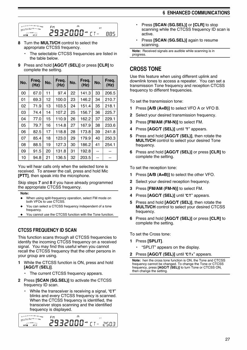
27
6 ENHANCED COMMUNICATIONS
• Press [SCAN (SG.SEL)] or [CLR] to stop scanning while the CTCSS frequency ID scan is active.
• Press [SCAN (SG.SEL)] again to resume scanning.
Note: Received signals are audible while scanning is in progress.
CROSS TONEUse this feature when using different uplink and downlink tones to access a repeater. You can set a transmission Tone frequency and reception CTCSS frequency to different frequencies.
To set the transmission tone:
1 Press [A/B (A=B)] to select VFO A or VFO B.
2 Select your desired transmission frequency.
3 Press [FM/AM (FM-N)] to select FM.
4 Press [AGC/T (SEL)] until “ ” appears.
5 Press and hold [AGC/T (SEL)], then rotate the MULTI/CH control to select your desired Tone frequency.
6 Press and hold [AGC/T (SEL)] or press [CLR] to complete the setting.
To set the reception tone:
1 Press [A/B (A=B)] to select the other VFO.
2 Select your desired reception frequency.
3 Press [FM/AM (FM-N)] to select FM.
4 Press [AGC/T (SEL)] until “ ” appears.
5 Press and hold [AGC/T (SEL)], then rotate the MULTI/CH control to select your desired CTCSS frequency.
6 Press and hold [AGC/T (SEL)] or press [CLR] to complete the setting.
To set the Cross tone:
1 Press [SPLIT].
• “SPLIT” appears on the display.
2 Press [AGC/T (SEL)] until “ ” appears.Note: hen the cross tone function is ON, the Tone and CTCSS frequency cannot be changed. To change the Tone or CTCSS frequency, press [AGC/T (SEL)] to turn Tone or CTCSS ON, then change the setting.
8 Turn the MULTI/CH control to select the appropriate CTCSS frequency.
• The selectable CTCSS frequencies are listed in the table below.
9 Press and hold [AGC/T (SEL)] or press [CLR] to complete the setting.
No. Freq. (Hz) No. Freq.
(Hz) No. Freq. (Hz) No. Freq.
(Hz)
00 67.0 11 97.4 22 141.3 33 206.5
01 69.3 12 100.0 23 146.2 34 210.7
02 71.9 13 103.5 24 151.4 35 218.1
03 74.4 14 107.2 25 156.7 36 225.7
04 77.0 15 110.9 26 162.2 37 229.1
05 79.7 16 114.8 27 167.9 38 233.6
06 82.5 17 118.8 28 173.8 39 241.8
07 85.4 18 123.0 29 179.9 40 250.3
08 88.5 19 127.3 30 186.2 41 254.1
09 91.5 20 131.8 31 192.8 -- --
10 94.8 21 136.5 32 203.5 -- --
You will hear calls only when the selected tone is received. To answer the call, press and hold Mic [PTT], then speak into the microphone.
Skip steps 7 and 8 if you have already programmed the appropriate CTCSS frequency.
Note: ◆ When using split-frequency operation, select FM mode on
both VFOs to use CTCSS.◆ You can select a CTCSS frequency independent of a tone
frequency.◆ You cannot use the CTCSS function with the Tone function.
CTCSS FREQUENCY ID SCANThis function scans through all CTCSS frequencies to identify the incoming CTCSS frequency on a received signal. You may find this useful when you cannot recall the CTCSS frequency that the other persons in your group are using.
1 While the CTCSS function is ON, press and hold [AGC/T (SEL)].
• The current CTCSS frequency appears.
2 Press [SCAN (SG.SEL)] to activate the CTCSS frequency ID scan.
• While the transceiver is receiving a signal, “ ” blinks and every CTCSS frequency is scanned. When the CTCSS frequency is identified, the transceiver stops scanning and the identified frequency is displayed.

COMMUNICATING AIDS
28
RECEPTION
SELECTING YOUR FREQUENCYIn addition to turning the Tuning control or pressing Mic [UP]/ [DWN], there are several other ways to select your frequency. This section describes additional methods of frequency selection that may save you time and effort.
■ Direct Frequency Entry When the desired frequency is far removed from
the current frequency, directly entering a frequency from the numeric keypad is usually the fastest method.
1 Press [ENT].
• “ - - . - - - . - - ” appears.
2 Press the numeric keys ([50 (0)] to [28 (9)]) to enter your desired frequency.
• Pressing [ENT] at any time fills the remaining digits (the digits you did not enter) with 0 and completes the entry. To select 1.85 MHz for example, press [ENT], [50 (0)], [1.8 (1)], [24 (8)], [14 (5)], then press [ENT] to complete the input (6 key strokes).
• Pressing [CLR] before pressing [ENT] cancels the entry and restores the current VFO frequency.
Note:◆ You can enter a frequency in the range of 30.00 kHz
to 59.999.99 MHz. Refer to the specifications for the available frequency range.
◆ Attempting to enter a frequency that is outside the selectable frequency range causes an alarm to sound and the entered frequency is rejected.
◆ When the entered frequency does not meet the current VFO frequency step size requirement, the nearest available frequency is automatically selected after the entered frequency is changed.
◆ When the 10 Hz digit (last displayed digit) is entered, the digit 0 is automatically entered for the 1 Hz digit, and frequency entry is completed. The 1 Hz digit is not displayed.
◆ When an entered frequency is accepted, RIT or XIT will be switched OFF, but the RIT or XIT offset frequency is not cleared.
■ Frequency Entry History The last 10 frequencies you entered are stored in
the Frequency Entry History. You can access the history to easily re-enter a recently used frequency.
1 Press [ENT].
2 Turn the MULTI/CH control.
• The entered frequency along with its log number appears. The most recent entered frequency is logged as number E0 and the oldest frequency is logged as number E9.
3 Press [ENT] to set the selected frequency to the VFO.
Note: When entering a frequency using the numeric keys, if you turn the MULTI/CH control in the middle of the frequency entry, the frequency will be entered into the log.
■ Using the MHz key
You can use the MULTI/CH control to change the operating frequency in steps of 1 MHz.
1 Press [MHz].
• “ ” appears.
2 Turn the MULTI/CH control.
• Clockwise increases the frequency and counter-clockwise decreases the frequency.
3 Press [MHz] again to exit.
• “ ” disappears.
If you prefer to change the frequency in steps of 100 kHz or 500 kHz, rather than 1 MHz, access Menu No. 10 and select 100 kHz, 500 kHz, or 1 MHz.
Note: Even if 100 kHz or 500 kHz is assigned for the [MHz] key, “ ” appears on the display.
■ Quick QSY
To move up or down the frequency quickly, use the MULTI/CH control. Turning this control changes the operating frequency in steps of 5 kHz for SSB/ CW/ FSK/ AM and steps of 10 kHz for FM.
• If you want to change the default frequency step size, access Menu No. 14 (SSB/CW/FSK), 15 (AM), or 16 (FM). Press [M.IN]/ [SCAN (SG.SEL)] to select 500 Hz, 1 kHz, 2.5 kHz, 5 kHz, or 10 kHz for SSB/ CW/ FSK, and 5 kHz, 6.25 kHz, 10 kHz, 12.5 kHz, 15 kHz, 20 kHz, 25 kHz, 30 kHz, 50 kHz, or 100 kHz for AM/ FM. The default frequency step size is 5 kHz for SSB/ CW/ FSK/ AM and 10 kHz for FM.
• When changing the operating frequency by using the MULTI/CH control, frequencies are rounded such that new frequencies are multiples of the frequency step size. To disable this function, access Menu No. 12 and select “oFF” (default is ON).
• Within the AM broadcast band, the step size automatically defaults to the frequency step value in Menu No. 13. This frequency step size can be switched between 9 kHz (“on”) and 5 kHz (“oFF”) via Menu No. 13.
Note: The programmed frequency step size for the MULTI/CH control is stored independently for the HF and 50 MHz bands. You can also set a different frequency step size for SSB/ CW/ FSK, AM and FM modes.

29
7 COMMUNICATING AIDS
■ Fine Tuning
The default frequency step size when turning the Tuning control to change the frequency is 10 Hz for SSB/ CW/ FSK, and 100 Hz for AM/ FM. However, you can change the frequency step size to 1 Hz for SSB/ CW/ FSK, and 10 Hz for AM/ FM.
1 Press [FINE (F.LOCK)].
• “ ” appears.
2 Turn the Tuning control to select the exact frequency.
3 To quit the function, press [FINE (F.LOCK)] again.
• “ ” disappears.
■ Tuning Control Adjustment Rate
The default Tuning control adjustment rate is 500. This represents the number of pulses the Tuning control generates in a complete revolution. Each pulse changes the tuning frequency based on the current frequency step size (the frequency step size for the Tuning control is 10 Hz for SSB/ CW/ FSK and 100 Hz for AM/ FM). For example, in SSB mode the frequency step size is 10 Hz, so the frequency would change by 5,000 Hz in a complete revolution of the Tuning control. The adjustment rate of the Tuning control can be lowered to 250 pulses per revolution or increased to 1000 pulses per revolution.
1 Press [MENU], then press [Q-M.IN]/ [Q-MR] or turn the MULTI/CH control to select Menu No. 11.
2 Press [M.IN]/ [SCAN (SG.SEL)] to select “250”, “500”, or “1000” (default).
3 Press [MENU] to exit Menu mode.
■ Equalizing VFO Frequencies (A=B)
This function allows you to copy the frequency and modulation mode of the active VFO to the inactive VFO.
1 Select the frequency and mode on VFO A or VFO B.
2 Press and hold [A/B (A=B)].
• The frequency and mode selected in step 1 are duplicated to the inactive VFO.
3 Press [A/B (A=B)] to confirm that the frequency was copied to other VFO.
RIT (RECEIVE INCREMENTAL TUNING)RIT provides the ability to change your reception frequency by ±9.99 kHz in steps of 10 Hz without changing your transmission frequency. If the Fine Tuning ([FINE (F.LOCK)]) function is ON, the frequency step size becomes 1 Hz (±9.999 kHz). RIT works equally well with all modulation modes and while using VFO or Memory Recall mode.
1 Press [RIT].
• “ ” and the RIT offset appear.
2 If required, press [CL] to reset the RIT offset to 0.
3 Turn the RIT/ XIT control to change your reception frequency.
4 To turn RIT OFF, press [RIT].
• The reception frequency is returned to the frequency that was selected prior to step 1.
Note: When storing the frequency in a Memory channel with the RIT function ON, the RIT offset frequency is added to or subtracted from the VFO frequency. The calculated data is then stored in the Memory channel.
AGC (AUTOMATIC GAIN CONTROL)When using a mode other than FM, AGC selects the time constant for the Automatic Gain Control circuit.
Selecting a slow time constant will cause the receiver gain and S-meter readings to react slowly to large input changes. A fast time constant causes the receiver gain and the S-meter to react quickly to changes in the input signal. A fast AGC setting is particularly useful in the following situations:
• Tuning rapidly
• Receiving weak signals
• Receiving high-speed CW
For your convenience, the following default AGC time constant has already been programmed.
SSB: Slow (“ ”) CW: Fast (“ ”)
FSK: Fast (“ ”) AM: Slow (“ ”)
■ AGC Time Constant Adjustment
You can pre-set up to 20 values (1 ~ 20) for the FAST/SLOW time constant (release time).
To change the default time constant:
1 Press [AGC/T (SEL)] to select FAST or SLOW.
• The AGC time constant icon appears on the display (“ ”: Slow, “ ”: Fast).
2 Press and hold [AGC/T (SEL)] to display the time constant pre-set value.
3 Turn the MULTI/CH control to set your desired time constant value.
4 If you want to turn the AGC OFF, press and hold [CW T. (AGC OFF)].
• “ ” appears on the display.Note: You cannot adjust the time constant in FM mode.

30
7 COMMUNICATING AIDS
TRANSMISSION
VOX (VOICE-OPERATED TRANSMISSION)VOX eliminates the necessity of manually switching to the transmission mode each time you want to transmit. The transceiver automatically switches to transmission mode when VOX senses that you have begun speaking into the microphone.
When using VOX, develop the habit of pausing between thoughts to allow the transceiver to drop back to reception mode briefly. You will then hear if anybody wants to interrupt, plus you will have a short period to gather your thoughts before speaking again. Your listeners will appreciate your consideration as well as respect your more articulate conversation.
Press [VOX (LEV)] to toggle between VOX ON and OFF.
• “ ” appears when the VOX function is ON.
■ Microphone Input Level
To enjoy the VOX function, take the time to properly adjust the VOX gain. This level controls the capability of VOX to detect the presence or absence of your voice. In CW mode, this level cannot be adjusted.
1 Select USB, LSB, FM, or AM mode.
2 Press [VOX (LEV)] to switch the VOX function ON.
• “ ” appears.
3 Press and hold [VOX (LEV)].
• The current VOX gain level appears on the sub-display.
4 While speaking into the microphone using your normal tone of voice, adjust the setting (default is 4) using the MULTI/CH control until the transceiver reliably switches to transmission mode each time you speak.
• The selectable gain range is from 0 to 9.
• The setting should not allow background noise to switch the transceiver to transmit mode.
Note: The VOX gain level can be adjusted even if VOX is switched OFF or while you are transmitting.
■ Delay Time
If the transceiver returns to reception mode too quickly after you stop speaking, your final word may not be transmitted. To avoid this, select an appropriate delay time that allows all of your words to be transmitted without an overly long delay after you stop speaking.
1 Select USB, LSB, FM, or AM mode.
2 Press [VOX (LEV)] to switch the VOX function ON.
• “ ” appears.
3 Press and hold [KEY (DELAY)].
• The current setting appears on the sub-display. The default is 50 (1500 ms).
4 While speaking into the microphone using your normal tone of voice, turn the MULTI/CH control such that the transceiver switches to reception mode after you have stopped talking.
• The selectable range is from 5 to 100 (150 ms to 3000 ms) in steps of 5, or OFF.
5 Press [CLR] to store the parameter and exit the setting mode.
■ Anti-VOX Adjustment
The TS-590S transceiver has a DSP IC to improve and customize incoming/ outgoing audio signals. When the VOX function is turned ON, the DSP IC adjusts the Anti-VOX level automatically, comparing the reception sound level and microphone input level. So, you never have to worry about adjusting the anti-VOX level.
Note: When connecting a headphone to the Phone jack, Anti-VOX will not function.
■ Data VOX
Although the microphone is normally used for VOX transmission, you can also utilize the audio input of the ACC2 or USB connector. When the transceiver detects an audio signal on the ACC2 or USB connector, it automatically transmits. You can select ACC2 or USB via Menu No. 63 (“Selecting a Data Transmission Line”) {page 58}.
1 Select USB, LSB, FM, or AM mode.
2 Press [MENU], then press [Q-M.IN]/ [Q-MR] or turn the MULTI/CH control to select Menu No. 69.
3 Press [M.IN] to set the VOX with DATA input function ON.
4 If necessary, adjust the VOX gain level for the ACC2 or USB connector {page 31}.
Note: While VOX with DATA input is set to ON (Menu No. 69), speaking into the microphone also activates the VOX function and you can still transmit using Mic [PTT]. Anti-VOX does not function with Data VOX.
While the Data VOX function remains ON and the transceiver is connected to a sound source, such as a PC, the transceiver may begin transmitting due to the sounds emitted from the sound source. To avoid unintended transmission while the transceiver is connected to the sound source, turn the Data VOX function OFF.

31
7 COMMUNICATING AIDS
■ Data VOX Delay Time
Select an appropriate delay time for after the audio signal input to the ACC2 or USB connector ends.
1 Press [MENU], then press [Q-M.IN]/ [Q-MR] or turn the MULTI/CH control to select Menu No. 70.
2 Press [M.IN]/ [SCAN (SG.SEL)] to set your desired delay time.
3 Press [MENU] to exit Menu mode.
■ USB/ ACC2 VOX Gain
When using the ACC2 or USB connector for VOX transmission, take the time to properly adjust the VOX gain.
1 Press [MENU], then press [Q-M.IN]/ [Q-MR] or turn the MULTI/CH control to select Menu No. 71 (USB connector) or Menu No. 72 (ACC2 connector).
2 While sending an audio signal to the ACC2 or USB connector, adjust the value (default is 4) using [M.IN]/ [SCAN (SG.SEL)] until the transceiver reliably switches to transmit mode each time you send an audio signal to the connector.
3 Press [MENU] to exit Menu mode.
SPEECH PROCESSORThe Speech Processor levels out large fluctuations in your voice while you speak. When using SSB, AM, or FM mode, this leveling action effectively raises the average TX power (SSB/AM) or raises the deviation to an adequate level (FM), resulting in a more understandable signal. The amount of voice compression is fully adjustable. Using the Speech Processor makes it easier to be heard by distant stations.
Level
Level
Time
Time
SpeechProcessorON
SpeechProcessorOFF
1 Select USB, LSB, AM, or FM mode.
2 Press [PROC (LEV)] to turn the Speech Processor ON.
• “ ” appears.
3 Press and hold [PROC (LEV)] to enter the Speech Processor input level adjustment mode.
4 As you speak into the microphone, turn the MULTI/CH control so that the compression meter indicates that the compression level is around 10 dB while you speak.
• Using higher compression will not improve your signal clarity or apparent signal strength. Excessively compressed signals are more difficult to understand due to distortion and are less pleasant to hear than signals with less compression.
5 Press and hold [PROC (LEV)] to exit the Speech Processor input level adjustment mode.
6 Press [MIC (CAR)] to enter the Speech Processor output level adjustment mode.
• As you speak into the microphone, turn the MULTI/CH control so that the ALC meter reflects according to your voice level, but does not exceed the ALC limit. Press [MIC (CAR)] to exit when you finish the adjustment.
■ Speech Processor Effect
When using the Speech Processor, you can change its effect.
1 Press [MENU], then press [Q-M.IN]/ [Q-MR] or turn the MULTI/CH control to select Menu No. 29.
2 Press [M.IN]/ [SCAN (SG.SEL)] to set the Processor Effect to SOFT or HARD (default).
3 Press [MENU] to exit Menu mode.
XIT (TRANSMIT INCREMENTAL TUNING)Similar to RIT, XIT provides the ability to change your transmission frequency by ±9.99 kHz in steps of 10 Hz without changing your reception frequency. If the Fine Tuning function is ON, the frequency step size becomes 1 Hz (±9.999 kHz).
1 Press [XIT].
• “ ” and the XIT offset appear.
2 If required, press [CL] to reset the XIT offset to 0.
3 Turn the RIT/ XIT control to change your transmit frequency.
4 To turn XIT OFF, press [XIT].
• “ ” and the offset frequency disappear. The transmission frequency is returned to the frequency that was selected prior to step 1.
Note:◆ If the Fine Tuning function is ON, you can adjust the
frequency within ±9.99 kHz.◆ The frequency shift set by the XIT control is also used by the
RIT function. Therefore, changing or clearing the XIT offset also affects the RIT offset.
◆ When the XIT frequency goes beyond the available transmission frequency, the transceiver automatically stops transmitting.

32
7 COMMUNICATING AIDS
CUSTOMIZING TRANSMISSION SIGNAL CHARACTERISTICSThe quality of your transmission signal is important, regardless of which on-air activity you pursue. However, it is easy to be casual and overlook this fact since you don’t listen to your own signal. The following sub-sections provide information that will help you tailor your transmission signal.
■ TX Filter Bandwidth (SSB/ AM)
Use Menu No. 25 to select one of the following TX low-cut filters: 10, 100, 200, 300 (default), 400, or 500 Hz.
Use Menu No. 26 to select one of the following TX high-cut filters: 2500, 2600, 2700 (default), 2800, 2900, or 3000 Hz.
■ TX Filter Bandwidth (LSB-DATA/ USB-DATA)
Use Menu No. 27 to select one of the following TX low-cut filters: 10, 100, 200, 300 (default), 400, or 500 Hz.
Use Menu No. 28 to select one of the following TX high-cut filters: 2500, 2600, 2700 (default), 2800, 2900, or 3000 Hz.
■ TX Equalizer (SSB/ AM/ FM)
Use Menu No. 30 to change the transmission frequency characteristics of your signal. You can select from 1 of 6 different transmission profiles including the default flat response. Selecting any of the following items from the Menu causes “ ” to appear on the display.
• Off (oFF):
The flat frequency response for SSB, FM, and AM (default).
• High boost 1 (Hb1)/ High boost 2 (Hb2):
Emphasizes higher audio frequencies; effective for a bassi voice. High boost 2 does not reduce the low frequency as much as High boost 1.
• Formant pass (FP):
Improves clarity by suppressing audio frequencies outside the normal voice frequency range.
• Bass boost 1 (bb1)/ Bass boost 2 (bb2):
Emphasizes lower audio frequencies; effective for a voice with more high frequency components. Bass boost 2 emphasizes more low frequency response.
• Conventional (c):
Emphasizes by 3 dB frequencies at 600 Hz and higher.
• User (U):
Reserved for the optional ARCP software. Off (oFF) is programmed at the factory as a default.
Frequency Response Curves
0.1 1.0 2.0
Amplitude
Audio frequency (kHz)
oFFHb2HPbb1c
Note: When using the ARCP-590, you can temporarily change each preset value.
TRANSMIT INHIBITTransmit Inhibit prevents the transceiver from being placed in transmission mode. No signal can be transmitted when this function is ON, even if Mic [PTT] is pressed.
• TX Inhibit OFF: Transmission is allowed.
• TX Inhibit ON: Transmission is not allowed.
Switch this function ON or OFF via Menu No. 60. The default is OFF.
BUSY LOCKOUTBusy Lockout prevents the transceiver from being placed in transmit mode if the current operating frequency is busy; in other words, if the squelch is open, you cannot transmit.
• Busy Lockout OFF: Transmission is allowed.
• Busy Lockout ON: Transmission is not allowed.
Switch this function ON or OFF via Menu No. 74. The default is OFF.
CHANGING FREQUENCY WHILE TRANSMITTINGMoving your frequency while transmitting is usually an unwise practice due to the risk of interfering with other stations. However, if necessary, by using the Tuning control you can change the operating frequency while transmitting. You also can change the XIT offset frequency while in transmission mode.
While transmitting, if you select a frequency outside the transmission frequency range, the transceiver is automatically forced to return to reception mode.

33
7 COMMUNICATING AIDS
CW BREAK-INBreak-in allows you to transmit CW without manually switching between transmission and reception modes. Two types of Break-ins are available: Semi Break-in and Full Break-in.
Semi Break-in:When the key contacts open, the transceiver automatically waits for the duration of the time period you selected. The transceiver then returns to reception mode.
Full Break-in:As soon as the key contacts open, the transceiver returns to reception mode.
USING SEMI BREAK-IN OR FULL BREAK-IN1 Press [CW/FSK (REV)] until you select CW mode.
• “CW” appears.
2 Press [VOX (LEV)].
• “ ” appears.
3 Press and hold [KEY (DELAY)].
• The current setting (FBK or delay time) appears. The default is 50 (500 ms).
4 Turn the MULTI/CH control to select “FBK” (Full Break-in) or a delay time for Semi Break-in.
• Delay time ranges from 5 to 100 (50 ms to 1000 ms) in steps of 5.
5 Begin sending.
• The transceiver automatically switches to transmission mode.
• When FBK (Full Break-in) is selected:The transceiver immediately switches to reception mode when the key opens.
• When a delay time is selected:The transceiver switches to reception mode after the delay time that you have selected has passed.
6 Press [CLR] to exit.Note: FBK (Full Break-in) cannot be used with the TL-922/ 922A linear amplifier.
ELECTRONIC KEYERThis transceiver has a built-in electronic keyer that can be used by connecting a keyer paddle to the transceiver’s rear panel. Refer to “Keys for CW (PADDLE and KEY)” {page 2} for details regarding this connection. The built-in keyer supports lambic (squeeze) operation.
ELECTRONIC KEYER MODEThere are 2 modes of operation when using an electronic keyer for lambic keying operation. Mode A completes the current key sequence you are sending when you release the paddles. Mode B sends one more key, opposite the current key you are sending, upon releasing the paddles.
1 Press [MENU], then press [Q-M.IN]/ [Q-MR] or turn the MULTI/CH control to select Menu No. 32.
2 Press [M.IN]/ [SCAN (SG.SEL)] to select “A” or “B” (default).
3 Press [MENU] to exit Menu mode.
CHANGING KEYING SPEEDThe keying speed of the electronic keyer is fully adjustable. Selecting the appropriate speed is important in order to send error-free CW that other operators can copy solidly. Selecting a speed that is beyond your keying ability will only result in mistakes. You will obtain the best results by selecting a speed that is close to the speed used by the other station.
1 Press [CW/FSK (REV)] until you select CW mode.
• “CW” appears.
2 Press [KEY (DELAY)].
• The current keying speed appears. The default is 20 (wpm).
3 While keying the paddle and listening to the TX (transmission) sidetone, turn the MULTI/CH control to select the appropriate speed.
• The speeds range from 4 to 60 wpm, in steps of 1 wpm. The larger the number, the faster the speed.
4 Press [KEY (DELAY)] again to complete the setting.
Note: When using the semi-automatic “Bug” function, the selected speed applies only to the rate that dots are sent.
■ Invalid Break-In Operation
You can make break-in operation invalid while performing the keying speed adjustment.
To switch this function ON, access Menu No. 43, and select “on” (default is “oFF”).
• “VOX” blinks when break-in operation is enabled.

34
7 COMMUNICATING AIDS
RISE TIME OF CWThe rise time of a CW signal is the time for the RF output to rise to its maximum power after the key is closed.
1 Press [MENU], then press [Q-M.IN]/ [Q-MR] or turn the MULTI/CH control to select Menu No. 35.
2 Press [M.IN]/ [SCAN (SG.SEL)] to select “1”, “2”, “4”, or “6” (default).
• The default setting of 6 ms is fine for slow or medium keying speeds and normal weighting (dot/ dash ratio). 1, 2, or 4 ms are good for faster keying speeds.
3 Press [MENU] to exit Menu mode.
AUTO WEIGHTINGThe electronic keyer can automatically change the dot/ dash weighting. Weighting is the ratio of dash length to dot length. The weighting changes with your keying speed automatically, thus making your keying easier for other operators to copy (default).
Access Menu No. 36 to select “AUto” or “2.5” ~ “4.0” (in steps of 0.1) fixed weight ratio. The default is “auto”. When a fixed weight ratio is selected, the dot/ dash weight ratio is locked, irregardless of the keying speed.
■ Reverse Keying Weight Ratio
Auto Weighting increases the weighting as you increase your keying speed. However, the electronic keyer also can decrease the weighting as you increase your keying speed.
To switch this function ON, access Menu No. 37, and select “on”. The default is OFF.
When setting Menu No. 36 to “Auto”, refer to the following.
Reverse Keying Weight
Keying Speed (wpm)
4 ~ 24 25 ~ 44 45 ~ 60
OFF 1:2.8 1:3.0 1:3.2
ON 1:3.2 1:3.0 1:2.8
BUG KEY FUNCTIONThe built-in electronic keyer can also be used as a semi-automatic key. Semi-automatic keys are also known as “Bugs”. When this function is ON, dots are generated in the normal manner by the electronic keyer. Dashes, however, are manually generated by the operator by holding the keyer paddle closed for the appropriate length of time.
To switch this function ON, access Menu No. 38 and select “on”. The default is OFF.
Note: When the Bug Key function is ON, CW Message Memory (see below) cannot be used.
CW MESSAGE MEMORYThis transceiver has 4 memory channels for storing CW messages. Each memory channel can store approximately 50 characters (equivalent of 250 dots). These memory channels are ideal for storing contest exchanges that you want to send repeatedly. Stored messages can be played back to check message content or for transmitting.
The electronic keyer has a function that allows you to interrupt playback and manually inject your own keying. To switch this function ON, access Menu No. 33 and select “on”. The default is OFF.
The electronic keyer can also repeatedly play back the message that you stored. To switch this function ON, access Menu No. 56 and select “on”. The default is OFF.
For repetitive message playback, you can change the interval between each series of messages. Use Menu No. 57 and select the time in the range of 0 to 60 seconds, in steps of 1 second.
Note:◆ This function cannot be used when the Bug Key function is
ON.◆ Operating the keyer paddle while Menu No. 33 is OFF,
cancels message playback. Even if message playback does not stop because of your keying start timing, you can cancel playback by pressing [CLR].
◆ When the constant recording function of the optional VGS-1 is ON, you cannot use [RX/4 (REC)].
■ Storing CW Messages
1 Press [CW/FSK (REV)] until you select CW mode.
• “CW” appears.
2 Press and hold [CH1 (REC)], [CH2 (REC)], [CH3 (REC)], or [RX/4 (REC)] to select a memory channel to be recorded.
• If Constant Recording is ON (Menu No. 55), you cannot store a message to [RX/4 (REC)] {page 60}. The default is ON.
3 Begin sending using the keyer paddle.
• The message you send is stored in memory.
4 To complete the message storage, press [CLR] or [CH1 (REC)]/ [CH2 (REC)]/ [CH3 (REC)]/ [RX/4 (REC)] to stop.
• When the number reaches 100(%), the memory becomes full and recording automatically stops.
Note: If you do not operate the keyer paddle after starting to record a message, a pause is stored in the channel.

35
7 COMMUNICATING AIDS
■ Checking CW Messages without Transmitting
1 Press [CW/FSK (REV)] until you select CW mode.
• “CW” appears.
2 If Break-in is ON, press [VOX (LEV)] to turn VOX OFF.
3 Press [CH1 (REC)], [CH2 (REC)], [CH3 (REC)], or [RX/4 (REC)] to select the channel to be played back.
• The message is played back.
• When Menu No. 56 is “oFF”, press and hold the current playback channel key to repeatedly play back the message saved to that key (a display such as “CP 1111” appears for the channel key you pressed.). To cancel the playback, press any channel key or [CLR].
• To play back the messages stored in the other channels in sequence, press the corresponding channel keys during playback. Up to 4 channels can be queued at the same time. (Repeat playback, by pressing and holding the keys, does not work during consecutive message playback.)
• While playing back the messages, you can also adjust the keyer speed by pressing [KEY (DELAY)] and turning the MULTI/CH control.
• To interrupt playback, press [CLR].
■ Transmitting CW Messages
Messages can be transmitted using Semi Break-in/ Full Break-in or manual TX/ RX switching.
1 Press [CW/FSK (REV)] until you select CW mode.
• “CW” appears.
2 To use Semi Break-in/ Full Break-in, press [VOX (LEV)].
• “ ” appears.
• If you are not using Semi Break-in/ Full Break-in, press [SEND].
3 Press [CH1 (REC)], [CH2 (REC)], [CH3 (REC)], or [RX/4 (REC)] select the channel to be played back.
• The message is played back and transmitted automatically.
• To transmit the messages stored in the other channels in sequence, press the corresponding channel keys during playback. Up to 4 channels can be queued at the same time.
• While playing back the messages, you can also adjust the keyer speed by pressing [KEY (DELAY)] and turning the MULTI/CH control.
• To cancel transmission, press [CLR].
■ Changing the Inter-message Interval Time
For the message playback repeat, access Menu No. 56 and select “on”. You can also change the interval playback time of the message. Access Menu No. 57 and select the time in the range of 0 to 60 seconds, in steps of 1 second.
Note: Menu Nos. 56 and 57 settings are shared with the voice communication modes when the optional VGS-1 is installed.
■ Changing the CW Sidetone Volume
Turning the AF control does not change the CW sidetone playback volume. To change the CW sidetone volume, access Menu No. 04 and select “oFF”, or “1” to “9”. The default is “5”.
■ Insert Keying
If you operate a CW keyer manually while playing back a recorded CW message, the transceiver stops playing back the message. However, during contests or regular QSOs, you may sometimes want to insert a different number or message at a certain point in the recorded message.
In this case, first record the CW message as usual {page 34}, without the additional number or message you want to insert. Then, access Menu No. 33 and select “on”.
Now, if you operate a CW keyer while you play back a recorded message, the transceiver pauses the playback of the recorded message, instead of stopping it. When you finish sending the number or message with the keyer, the transceiver resumes playback of the message.
FREQUENCY CORRECTION FOR CWIf you operate both SSB and CW modes, you would sometimes use SSB mode (USB or LSB) just to watch and listen to CW signals. It is fine just to monitor those CW signals but you have experienced that changing the mode from SSB to CW results in losing the target CW signal. This is because the frequency on the display always shows the true carrier frequency for all modes. If you want the transceiver to shift the reception frequency to trace the receiving CW signal when changing the mode from SSB (USB or LSB) to CW, switch this function ON. The transceiver shifts the reception frequency when changing the mode from SSB to CW, so you can still hear the target signal and instantly transmit the signal in CW without adjusting the frequency.
1 Press [MENU], then press [Q-M.IN]/ [Q-MR] or turn the MULTI/CH control to select Menu No. 42.
2 Press [M.IN] to select “on”.
3 Press [MENU] to exit Menu mode.
36
7 COMMUNICATING AIDS
AUTO CW TX IN SSB MODEIf you operate both SSB and CW modes, you can configure the transceiver to change the operating mode from SSB (USB or LSB) to CW and then transmit in CW mode automatically when you operate the CW keyers.
The mode automatically changes from USB to CW and LSB to CWR, regardless of the setting for Menu No. 42 (Frequency correction for changing SSB to CW). Therefore, when the CW signal is received in SSB mode, you can operate the paddle or keyer to immediately communicate CW with another station.
1 Press [MENU], then press [Q-M.IN]/ [Q-MR] or turn the MULTI/CH control to access Menu No. 41.
2 Press [M.IN] to select “on”.
3 Press [MENU] to exit Menu mode.Note: You must switch the CW Break-in function ON to change the mode and transmit in CW mode {page 32}.
MIC UP/ DWN KEY PADDLE MODEThis function allows you to send CW messages without using an optional paddle {page 2}. The Mic [UP] key can be used as the dot paddle and the Mic [DWN] key can be used as the dash paddle.
To activate Mic UP/ DWN key Paddle mode:
1 Press [MENU], then press [Q-M.IN]/ [Q-MR] or turn the MULTI/CH control to access Menu No. 40.
2 Press [M.IN] to select “PA”.
3 Press [MENU] to exit Menu mode.
• Press and hold Mic [DWN] to send dots or Mic [UP] to send dashes in CW mode.
4 To exit Mic UP/ DWN key Paddle mode, access Menu No. 40 and select “PF”.
SWAP DOT AND DASH PADDLE POSITIONSThis function reverses the position of the dot and dash paddle positions. As a default, the left paddle sends dots and the right paddle sends dashes. When this function is ON, the left paddle will send dashes and the right paddle will send dots.
1 Press [MENU], then press [Q-M.IN]/ [Q-MR] or turn the MULTI/CH control to access Menu No. 39.
2 Press [M.IN] to select “on”.
3 Press [MENU] to exit Menu mode.
• The left paddle now sends dashes and the right paddle now sends dots. To return to the normal paddle positions, access Menu No. 39 and select “oFF”.

37
DATA COMMUNICATIONS
RADIO TELETYPE (RTTY)RTTY is the data communications mode with the longest history. It was originally designed for use with mechanical teletypewriters which were often used before personal computers became common. Now you can easily start operating RTTY with a personal computer and MCP. Unlike Packet, each time you type a letter, it is transmitted over the air. What you type is transmitted and displayed on the computer screen of the recipient.
RTTY operation uses frequency shift keying (FSK) and the 5-bit Baudot code or the 7-bit ASCII code to transmit information.
For cable connections, refer to “RTTY OPERATION” {page 68}.
For further information, consult reference books about Amateur Radio.
1 Access Menu No. 44 and select an FSK shift.
• FSK shift is the difference in frequencies between a mark and a space.
• The 170 Hz shift (default) is normally used on the Amateur bands for the RTTY.
2 Access Menu No. 45 and select a key-down polarity.
• Select “oFF” (default) to transmit a mark when keying down or “on” to transmit a space.
3 Access Menu No. 46 and select “2125” (high tone) or “1275” (low tone) for mark.
• High tone (default) is commonly used nowadays.
4 Select an operating frequency.
5 Press [CW/FSK (REV)] to select FSK mode.
• “FSK” appears.
• If necessary, access Menu No. 67 to configure the appropriate audio output level for your MCP. The audio output level of ANO (ACC2 connector/ pin 3) changes {page 65}. The AF control cannot be used to adjust the audio level for your MCP.
6 Some stations may be operating in Reverse shift. In this case, press and hold [CW/FSK (REV)] to reverse the shift (the upper sideband is used).
• “FSR” appears.
• Traditionally, the lower sideband is used for FSK operation. Press and hold [CW/FSK (REV)] again to return to the lower sideband. “FSK” appears.
7 Follow the instructions provided with your MCP and enter a command from your computer to transmit.
• The TX-RX LED changes from green (RX) to red (TX).
8 Begin sending data from your computer.
• Press and hold [PWR (TX MONI)] to monitor your signals. Press and hold [PWR (TX MONI)] again to quit this function.
9 When finished transmitting, enter a command from your computer to return to reception mode.
• The TX-RX LED changes from red (TX) to green (RX).
The following frequencies (measured in kHz) are commonly used for RTTY operation:
U.S.A./ Canada IARU Region 1(Europe/ Africa)
1800 ~ 1840 1838 ~ 1842
3605 ~ 3645 (DX: 3590) 3580 ~ 3620
7080 ~ 7100 (DX: 7040) 7035 ~ 7045
10140 ~ 10150 10140 ~ 10150
14070 ~ 14099.5 14080 ~ 14099.5
18100 ~ 18110 18101 ~ 18109
21070 ~ 21100 21080 ~ 21120
24920 ~ 24930 22920 ~ 24929
28070 ~ 28150 28050 ~ 28150
PHASE-SHIFT KEYING 31 BAUD (PSK31)PSK31 is a digital modulation method used in amateur radio communications. You can perform data communications in real-time using a keyboard, like RTTY. Additionally, because of the narrow bandwidth (31.25 Hz) you can even use PSK31 on congested frequencies. Another merit to PSK31 is that it can be enjoyed with a simple antenna and low transmit power.
Using the sound function of your PC along with PSK31 software, many amateur radio operators enjoy PSK31.
• Refer to “TNC AND MCP” {page 69} for connections.
• When managing PSK31 using the sound capability of a PC, use SSB mode.
• Set AGC to fast.
• Turn off the speech processor.
• Refer to “EXTERNAL AUDIO SETTINGS” {page 58} for Audio Settings.
For further information, consult reference books about Amateur Radio.

38
REJECTING INTERFERENCE
■ CW/ FSK Mode
1 Select CW or FSK mode.
2 Turn the LO/WIDTH control clockwise to increase the bandwidth (wide), or counterclockwise to decrease the bandwidth (narrow).
Before
Interferingsignal
Interferingsignal
After
Desired signal
Mode Bandwidth Selection (Hz) Default
CW50, 80, 100, 150, 200, 250, 300, 400, 500, 600, 1000, 1500, 2000, 2500
500 Hz
FSK 250, 500, 1000, 1500 500 Hz
3 As for CW, you can further adjust the shift frequency for the pass band. Turn the HI/SHIFT control clockwise to increase the shift frequency (high), or counterclockwise to decrease the shift frequency (low).
Shift Frequency (Hz) Default
300, 350, 400, 450, 500, 550, 600, 650, 700, 750, 800, 850, 900, 950, 1000
800 Hz
■ Data Mode
1 Select Data mode (USB-DATA/LSB-DATA).
2 Turn the LO/WIDTH control clockwise to increase the bandwidth (wide), or counterclockwise to decrease the bandwidth (narrow).
Bandwidth Selection (Hz) Default
50, 80, 100, 150, 200, 250, 300, 400, 500, 600, 1000, 1500, 2000, 2500 2500 Hz
3 Turn the HI/SHIFT control clockwise to increase the shift frequency (high), or counterclockwise to decrease the shift frequency (low).
Shift Frequency (Hz) Default
1000, 1100, 1200, 1300, 1400, 1500, 1600, 1700, 1800, 1900, 2000, 2100, 2210
1500 Hz
■ IF Filter A and B
This transceiver has 2 built-in IF filters: A and B. The IF Filter settings are stored with the last settings of the LO/WIDTH and HI/SHIFT controls.
Press [IF FIL] to toggle between IF Filter setting A and B.
• “ ” appears when IF filter setting A is selected and “ ” appears when IF filter setting B is selected.
DSP FILTERSKenwood digital signal processing (DSP) technology is adapted to this transceiver. Using DSP filtering (AF), you can control the bandwidth, cancel the multiple jamming beat, and reduce the noise level.
CHANGING THE DSP FILTER BANDWIDTHFor improving interference reduction capability, this transceiver also provides IF filters designed using DSP technology. When in SSB, FM, or AM mode, you can change the filter bandwidth by altering its low and/or high cut-off frequency. For CW, FSK, and DATA modes, you can change the filter bandwidth by directly specifying a bandwidth. Changing the filter bandwidth does not affect the current receive frequency.
• The meter display changes, based on the bandwidth you are setting up.
■ SSB/ FM/ AM Mode
1 Select SSB, FM, or AM mode.
2 Turn the LO/WIDTH control clockwise to raise the low cut-off frequency, or counterclockwise to lower the low cut-off frequency.
Mode Low cut Frequency (Hz) Default
SSB/ FM
0, 50, 100, 200, 300, 400, 500, 600, 700, 800, 900, 1000 300 Hz
AM 0, 100, 200, 300 100 Hz
Turn the HI/SHIFT control clockwise to raise the high cut-off frequency, or counterclockwise to lower the high cut-off frequency.
Mode High cut Frequency (Hz) Default
SSB/ FM
1000, 1200, 1400, 1600, 1800, 2000, 2200, 2400, 2600, 2800, 3000, 3400, 4000, 5000
2600 Hz
AM 2500, 3000, 4000, 5000 5000 Hz
Low cut-off frequency
Interferingsignal
Interferingsignal
Desired signal
High cut-off frequency
0 Hz 1 KHz 5 KHz
Note: The cut-off frequencies can be adjusted independently for each operating mode. When you change the operating mode, the previous setting is recalled for each operating mode.

39
9 REJECTING INTERFERENCE
Press and hold [IF FIL] to momentarily display each setting value of the DSP filter band as follows:
SSB/ AM/ FM mode: High cut Frequency > Low cut Frequency
CW/ SSB data mode: Shift Frequency > Bandwidth
FSK mode: Bandwidth only
AUTO NOTCH FILTER (SSB)The Auto Notch filter automatically locates and attenuates any single interfering tone within the receive pass band. This function operates digitally at the IF filter level, hence it can affect your S-meter reading and may also affect (slightly attenuate) your desired signal. However, controlling the AGC level by notching out the strong interfering beat signals could bring up the desired SSB signal that is covered by the interfering beat signal. If the interfering tone is weak, you may find that Beat Cancel eliminates them more effectively.
Before
Interferingtones
After
Receive pass band
Desiredsignal
Press and hold [BC (A.NOTCH)] to toggle the Auto Notch Filter ON and OFF.
• “ ” appears when this function is ON.
• The interfering beat signals are notched out.
■ Auto Notch Tracking Speed
If the interfering beat signals change the tone frequency randomly, you can adjust the Auto Notch tracking speed.
1 Press [MENU], then press [Q-M.IN]/ [Q-MR] or turn the MULTI/CH control to select Menu No. 24
2 Press [M.IN]/ [SCAN (SG.SEL)] to select the level from FIX (0), and 1 to 4.
• Level 1 is the slowest beat tone tracking speed and Level 4 is the fastest. FIX terminates the beat tone tracking. Adjust this parameter manually to remove the beat signal if necessary.
3 Press [MENU] to exit Menu mode.
MANUAL NOTCH FILTER (SSB/ CW/ FSK)Use manual notch when you want to vary the width of the notch while verifying the interfering signal.
1 Press [NOTCH (WIDE)] to toggle the Manual Notch Filter ON and OFF.
• “ ” appears when this function is ON.
2 Turn the NOTCH control to adjust to the point where beat noise just disappears.
■ Notch Filter Bandwidth
Press and hold [NOTCH (WIDE)] to toggle the Notch filter bandwidth between NORMAL and WIDE.
• “ ” appears when the Notch filter bandwidth is set to WIDE.
BEAT CANCEL (SSB/ AM)Two types of Beat Cancel DSP filters are available. Beat Cancel 1 (BC1) is effective for removing a weak beat or continuous beat signals. Beat Cancel 2 (BC2) is effective for removing intermittent beat signals, such as CW signals.
Before
Interferingtones
After
Filter pass band (AF)
Desiredsignal
Press [BC (A.NOTCH)] to cycle through Beat Cancel 1, Beat Cancel 2, and OFF.
• “ ” or “ ” appears when the Beat Cancel function is ON.
• The interfering beat signals are removed.
NOISE REDUCTION (ALL MODES)This transceiver provides 2 types of Noise Reduction functions (NR1 and NR2) for reducing random noise which interferes with the desired signal.
NR1 differs, depending on the reception mode. When receiving a voice call in SSB/ FM/ AM mode, noise reduction uses a spectrum subtraction system. When receiving a non-voice call in CW/ FSK mode, noise reduction uses a LMS adaptive filter which emphasizes the periodic signal.
NR2 uses a SPAC format, which extracts a periodic signal from within the received signal.
Press [NR (LEV)] to cycle between NR1, NR2, and OFF.
• “ ” or “ ” appears, depending on which noise reduction filter is selected.

40
9 REJECTING INTERFERENCE
■ Setting the NR1 Level Adjustment
NR1 uses an adaptive filter to reduce the noise element from the received signals. When the S/N ratio is reasonably good in SSB, using NR1 will improve the S/N further.
While NR1 is ON, you can further adjust the noise reduction level by pressing and holding [NR (LEV)], then turning the MULTI/CH control to select the level from 1 to 10. The default is 5. The level is saved separately for SSB/FM/AM and CW/FSK.
■ Setting the NR2 Time Constant
You can change the correlation time for NR2 (SPAC). When in SSB mode, select the correlation time that allows you to hear signals with clarity. When receiving CW, it is best to select the longest correlation time that allows reliable reception. The longer the correlation time, the better the S/N ratio.
When NR2 is ON, press and hold [NR (LEV)], then turn the MULTI/CH control to select the correlation time from 2 to 20 ms. The default is 20 ms.
Note:◆ When using Noise Reduction 1 in SSB, FM, or AM
mode, the beat signal is suppressed along with the normal signal. This is not a malfunction.
◆ Using Noise Reduction 2 in SSB mode may lower the clarity of signals or induce pulse noise, depending on the conditions.
NOISE BLANKERThe Noise Blanker is designed to reduce pulse noise such as that generated by automobile ignitions. The Noise Blanker does not function in FM mode.
• NB1 performs blanking through an analog circuit. NB2 performs blanking using DSP.
Press [NB (LEV)] to cycle between Noise Blanker 1, Noise Blanker 2, and OFF.
• “ ” or “ ” appears, depending on which Noise Blanker is selected.
You can further adjust the Noise Blanker level from 1 to 10. The default level is 6. Press and hold [NB (LEV)], then turn the MULTI/CH control to adjust the Noise Blanker level.
• “NB LV.” and the current level appear on the sub-display.
Note:◆ The Noise Blanker is available only for SSB, CW, FSK, and
AM modes.◆ Increasing the Noise Blanker level degrades the
intermodulation characteristics of the transceiver.◆ For effective Noise Blanker operation, experiment with both
NB1 and NB2 on each band.◆ When using Noise Blanker 2 and a CW signal is received,
there are times when the received signal may be distorted. This is not a malfunction.
PRE-AMPLIFIERSwitching the pre-amplifier OFF may help reduce interference from adjacent frequencies.
Press [PRE (ANT 1/2)] to toggle the pre-amplifier ON and OFF.
• “ ” appears when this function is ON.
The ON/ OFF setting will be automatically stored in the current band. Each time you select the same band, the same setting will be automatically selected The frequency range of each band is provided in the table below (under “ATTENUATOR”).
ATTENUATORThe Attenuator reduces the level of received signals. This function is useful when there is strong interference from adjacent frequencies.
Press [ATT (RX ANT)] to toggle the attenuator ON and OFF.
• “ ” appears when this function is ON.
The ON/ OFF setting will be automatically stored in the current band. Each time you select the same frequency band, the attenuator setting will be automatically recalled. The frequency range of each band is shown below.
Frequency Band (MHz)
Pre-amplifier (Default)
Attenuator (Default)
0.03 ~ 0.522 OFF OFF
0.522 ~ 2.5 OFF OFF
2.5 ~ 4.1 OFF OFF
4.1 ~ 6.9 OFF OFF
6.9 ~ 7.5 OFF OFF
7.5 ~ 10.5 ON OFF
10.5 ~ 14.5 ON OFF
14.5 ~ 18.5 ON OFF
18.5 ~ 21.5 ON OFF
21.5 ~ 25.5 ON OFF
25.5 ~ 30.0 ON OFF
30.0 ~ 60.0 ON OFF
CW REVERSE (RECEPTION)This function pivots the BFO from the default position (USB) to another position (LSB) in CW mode. It is sometimes effective to remove the interfering signals from the IF passband by pivoting the BFO.
1 Press [CW/FSK (REV)] until “CW” appears.
2 Press and hold [CW/FSK (REV)].
• “CW” changes to “CWR”.
3 To recover the default BFO position, press and hold [CW/FSK (REV)] again.
• “CWR” changes to “CW”.
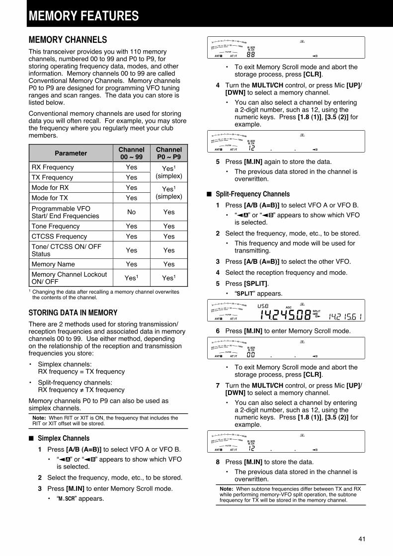
41
MEMORY FEATURES
MEMORY CHANNELSThis transceiver provides you with 110 memory channels, numbered 00 to 99 and P0 to P9, for storing operating frequency data, modes, and other information. Memory channels 00 to 99 are called Conventional Memory Channels. Memory channels P0 to P9 are designed for programming VFO tuning ranges and scan ranges. The data you can store is listed below.
Conventional memory channels are used for storing data you will often recall. For example, you may store the frequency where you regularly meet your club members.
Parameter Channel 00 ~ 99
Channel P0 ~ P9
RX Frequency Yes Yes1 (simplex)TX Frequency Yes
Mode for RX Yes Yes1 (simplex)Mode for TX Yes
Programmable VFO Start/ End Frequencies
No Yes
Tone Frequency Yes Yes
CTCSS Frequency Yes Yes
Tone/ CTCSS ON/ OFF Status Yes Yes
Memory Name Yes Yes
Memory Channel Lockout ON/ OFF Yes1 Yes1
1 Changing the data after recalling a memory channel overwrites the contents of the channel.
STORING DATA IN MEMORYThere are 2 methods used for storing transmission/reception frequencies and associated data in memory channels 00 to 99. Use either method, depending on the relationship of the reception and transmission frequencies you store:
• Simplex channels:RX frequency = TX frequency
• Split-frequency channels:RX frequency ≠ TX frequency
Memory channels P0 to P9 can also be used as simplex channels.
Note: When RIT or XIT is ON, the frequency that includes the RIT or XIT offset will be stored.
■ Simplex Channels
1 Press [A/B (A=B)] to select VFO A or VFO B.
• “ ” or “ ” appears to show which VFO is selected.
2 Select the frequency, mode, etc., to be stored.
3 Press [M.IN] to enter Memory Scroll mode.
• “ ” appears.
• To exit Memory Scroll mode and abort the storage process, press [CLR].
4 Turn the MULTI/CH control, or press Mic [UP]/ [DWN] to select a memory channel.
• You can also select a channel by entering a 2-digit number, such as 12, using the numeric keys. Press [1.8 (1)], [3.5 (2)] for example.
5 Press [M.IN] again to store the data.
• The previous data stored in the channel is overwritten.
■ Split-Frequency Channels
1 Press [A/B (A=B)] to select VFO A or VFO B.
• “ ” or “ ” appears to show which VFO is selected.
2 Select the frequency, mode, etc., to be stored.
• This frequency and mode will be used for transmitting.
3 Press [A/B (A=B)] to select the other VFO.
4 Select the reception frequency and mode.
5 Press [SPLIT].
• “ ” appears.
6 Press [M.IN] to enter Memory Scroll mode.
• To exit Memory Scroll mode and abort the storage process, press [CLR].
7 Turn the MULTI/CH control, or press Mic [UP]/ [DWN] to select a memory channel.
• You can also select a channel by entering a 2-digit number, such as 12, using the numeric keys. Press [1.8 (1)], [3.5 (2)] for example.
8 Press [M.IN] to store the data.
• The previous data stored in the channel is overwritten.
Note: When subtone frequencies differ between TX and RX while performing memory-VFO split operation, the subtone frequency for TX will be stored in the memory channel.
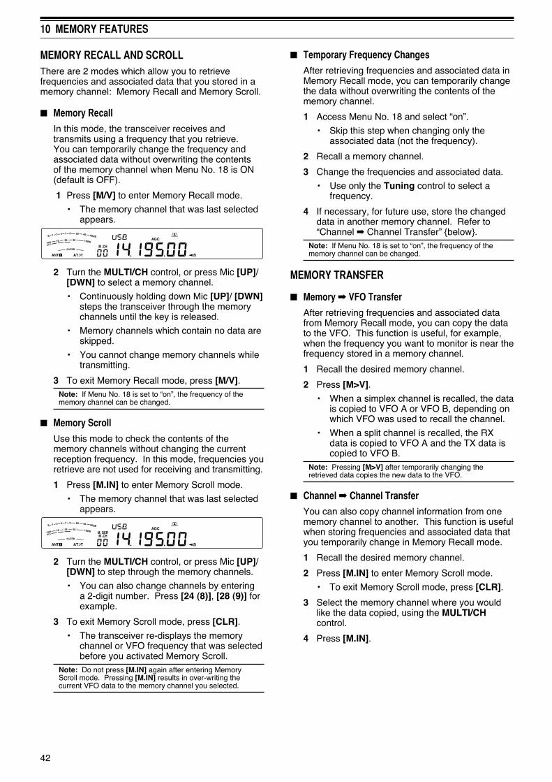
42
10 MEMORY FEATURES
■ Temporary Frequency Changes
After retrieving frequencies and associated data in Memory Recall mode, you can temporarily change the data without overwriting the contents of the memory channel.
1 Access Menu No. 18 and select “on”.
• Skip this step when changing only the associated data (not the frequency).
2 Recall a memory channel.
3 Change the frequencies and associated data.
• Use only the Tuning control to select a frequency.
4 If necessary, for future use, store the changed data in another memory channel. Refer to “Channel ➡ Channel Transfer” {below}.
Note: If Menu No. 18 is set to “on”, the frequency of the memory channel can be changed.
MEMORY TRANSFER
■ Memory ➡ VFO Transfer
After retrieving frequencies and associated data from Memory Recall mode, you can copy the data to the VFO. This function is useful, for example, when the frequency you want to monitor is near the frequency stored in a memory channel.
1 Recall the desired memory channel.
2 Press [M>V].
• When a simplex channel is recalled, the data is copied to VFO A or VFO B, depending on which VFO was used to recall the channel.
• When a split channel is recalled, the RX data is copied to VFO A and the TX data is copied to VFO B.
Note: Pressing [M>V] after temporarily changing the retrieved data copies the new data to the VFO.
■ Channel ➡ Channel Transfer
You can also copy channel information from one memory channel to another. This function is useful when storing frequencies and associated data that you temporarily change in Memory Recall mode.
1 Recall the desired memory channel.
2 Press [M.IN] to enter Memory Scroll mode.
• To exit Memory Scroll mode, press [CLR].
3 Select the memory channel where you would like the data copied, using the MULTI/CH control.
4 Press [M.IN].
MEMORY RECALL AND SCROLLThere are 2 modes which allow you to retrieve frequencies and associated data that you stored in a memory channel: Memory Recall and Memory Scroll.
■ Memory Recall
In this mode, the transceiver receives and transmits using a frequency that you retrieve. You can temporarily change the frequency and associated data without overwriting the contents of the memory channel when Menu No. 18 is ON (default is OFF).
1 Press [M/V] to enter Memory Recall mode.
• The memory channel that was last selected appears.
2 Turn the MULTI/CH control, or press Mic [UP]/ [DWN] to select a memory channel.
• Continuously holding down Mic [UP]/ [DWN] steps the transceiver through the memory channels until the key is released.
• Memory channels which contain no data are skipped.
• You cannot change memory channels while transmitting.
3 To exit Memory Recall mode, press [M/V].Note: If Menu No. 18 is set to “on”, the frequency of the memory channel can be changed.
■ Memory Scroll
Use this mode to check the contents of the memory channels without changing the current reception frequency. In this mode, frequencies you retrieve are not used for receiving and transmitting.
1 Press [M.IN] to enter Memory Scroll mode.
• The memory channel that was last selected appears.
2 Turn the MULTI/CH control, or press Mic [UP]/ [DWN] to step through the memory channels.
• You can also change channels by entering a 2-digit number. Press [24 (8)], [28 (9)] for example.
3 To exit Memory Scroll mode, press [CLR].
• The transceiver re-displays the memory channel or VFO frequency that was selected before you activated Memory Scroll.
Note: Do not press [M.IN] again after entering Memory Scroll mode. Pressing [M.IN] results in over-writing the current VFO data to the memory channel you selected.

43
10 MEMORY FEATURES
Channel 00 ~ 99 ➡ Channel 00 ~ 99
RX frequency ➡ RX frequency
TX frequency ➡ TX frequency
Mode for RX ➡ Mode for RX
Mode for TX ➡ Mode for TX
Tone frequency ➡ Tone frequency
CTCSS frequency ➡ CTCSS frequency
Tone/ CTCSS ON/ OFF status ➡
Tone/ CTCSS ON/ OFF status
Memory Name ➡ Memory Name
Memory Channel Lockout ON/ OFF ➡
Memory Channel Lockout OFF
Channel 00 ~ 99 ➡ Channel P0 ~ P9
RX frequency
➡ TX/RX frequency
➡ Start frequency
➡ End frequency
Mode for RX ➡ Mode for TX/RX
TX frequency ➡ ––
Mode for TX ➡ ––
Tone frequency ➡ Tone frequency
CTCSS frequency ➡ CTCSS frequency
Tone/ CTCSS/ Cross tone ON/ OFF status
➡Tone/ CTCSS/ Cross tone ON/ OFF status
Memory Name ➡ Memory Name
Memory Channel Lockout ON/ OFF ➡
Memory Channel Lockout OFF
Channel P0 ~ P9 ➡ Channel 00 ~ 99
TX/RX frequency➡ RX frequency
➡ TX frequency
Mode for TX/RX➡ Mode for RX
➡ Mode for TX
Start frequency ➡ ––
End frequency ➡ ––
Tone frequency ➡ Tone frequency
CTCSS frequency ➡ CTCSS frequency
Tone/ CTCSS/ Cross tone ON/ OFF status
➡Tone/ CTCSS/ Cross tone ON/ OFF status
Memory Name ➡ Memory Name
Memory Channel Lockout ON/ OFF ➡
Memory Channel Lockout OFF
Channel P0 ~ P9 ➡ Channel P0 ~ P9
TX/RX frequency ➡ TX/RX frequency
Start frequency ➡ Start frequency
End frequency ➡ End frequency
Mode for TX/RX ➡ Mode for TX/RX
Tone frequency ➡ Tone frequency
CTCSS frequency ➡ CTCSS frequency
Tone/ CTCSS/ Cross tone ON/ OFF status
➡Tone/ CTCSS/ Cross tone ON/ OFF status
Memory Name ➡ Memory Name
Memory Channel Lockout ON/ OFF ➡
Memory Channel Lockout OFF
Note: After copying, the Memory Channel Lockout turns OFF.
STORING FREQUENCY RANGESMemory channels P0 to P9 allow you to store frequency ranges for VFO tuning and Program Scan. Program Scan is described in the next chapter. To tune or scan frequencies within a specified range, store the start and end frequencies for that range in advance.
1 Press [A/B (A=B)] to select VFO A or VFO B.
2 Select the desired start frequency.
3 Press [M.IN] to enter Memory Scroll mode.
• To exit Memory Scroll mode and abort the storage process, press [CLR].
4 Turn the MULTI/CH control, or press Mic [UP]/ [DWN] to select a memory channel in the range of P0 to P9.
5 Press [M.IN] to store the start frequency in the memory channel.
• “ENDINPUT” appears on the sub-display.
6 Turn the Tuning control or MULTI/CH control to select the end frequency.
7 Press [M.IN] to store the end frequency in the memory channel.
• The previous data stored in the channel is overwritten.
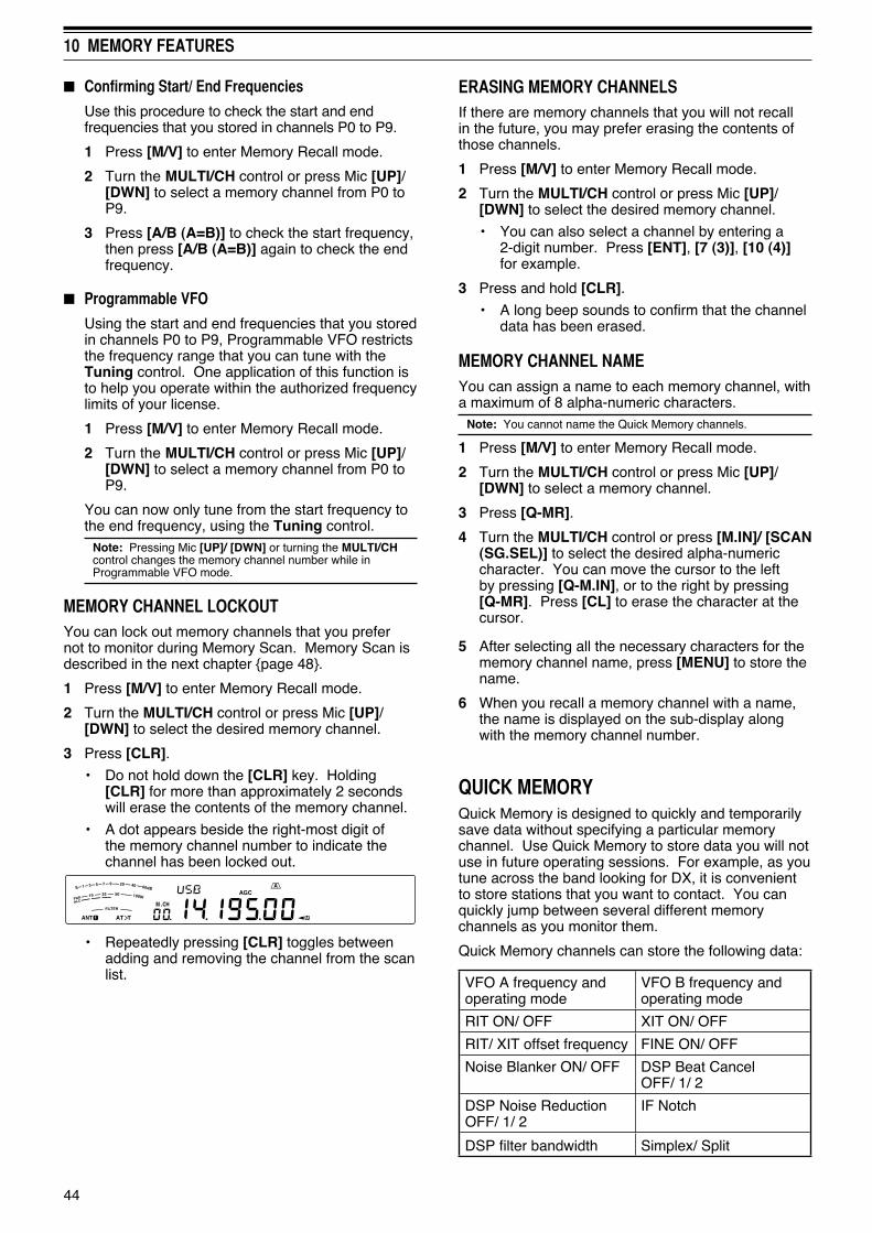
44
10 MEMORY FEATURES
■ Confirming Start/ End Frequencies
Use this procedure to check the start and end frequencies that you stored in channels P0 to P9.
1 Press [M/V] to enter Memory Recall mode.
2 Turn the MULTI/CH control or press Mic [UP]/ [DWN] to select a memory channel from P0 to P9.
3 Press [A/B (A=B)] to check the start frequency, then press [A/B (A=B)] again to check the end frequency.
■ Programmable VFO
Using the start and end frequencies that you stored in channels P0 to P9, Programmable VFO restricts the frequency range that you can tune with the Tuning control. One application of this function is to help you operate within the authorized frequency limits of your license.
1 Press [M/V] to enter Memory Recall mode.
2 Turn the MULTI/CH control or press Mic [UP]/ [DWN] to select a memory channel from P0 to P9.
You can now only tune from the start frequency to the end frequency, using the Tuning control.
Note: Pressing Mic [UP]/ [DWN] or turning the MULTI/CH control changes the memory channel number while in Programmable VFO mode.
MEMORY CHANNEL LOCKOUTYou can lock out memory channels that you prefer not to monitor during Memory Scan. Memory Scan is described in the next chapter {page 48}.
1 Press [M/V] to enter Memory Recall mode.
2 Turn the MULTI/CH control or press Mic [UP]/ [DWN] to select the desired memory channel.
3 Press [CLR].
• Do not hold down the [CLR] key. Holding [CLR] for more than approximately 2 seconds will erase the contents of the memory channel.
• A dot appears beside the right-most digit of the memory channel number to indicate the channel has been locked out.
• Repeatedly pressing [CLR] toggles between adding and removing the channel from the scan list.
ERASING MEMORY CHANNELSIf there are memory channels that you will not recall in the future, you may prefer erasing the contents of those channels.
1 Press [M/V] to enter Memory Recall mode.
2 Turn the MULTI/CH control or press Mic [UP]/ [DWN] to select the desired memory channel.
• You can also select a channel by entering a 2-digit number. Press [ENT], [7 (3)], [10 (4)] for example.
3 Press and hold [CLR].
• A long beep sounds to confirm that the channel data has been erased.
MEMORY CHANNEL NAMEYou can assign a name to each memory channel, with a maximum of 8 alpha-numeric characters.
Note: You cannot name the Quick Memory channels.
1 Press [M/V] to enter Memory Recall mode.
2 Turn the MULTI/CH control or press Mic [UP]/ [DWN] to select a memory channel.
3 Press [Q-MR].
4 Turn the MULTI/CH control or press [M.IN]/ [SCAN (SG.SEL)] to select the desired alpha-numeric character. You can move the cursor to the left by pressing [Q-M.IN], or to the right by pressing [Q-MR]. Press [CL] to erase the character at the cursor.
5 After selecting all the necessary characters for the memory channel name, press [MENU] to store the name.
6 When you recall a memory channel with a name, the name is displayed on the sub-display along with the memory channel number.
QUICK MEMORYQuick Memory is designed to quickly and temporarily save data without specifying a particular memory channel. Use Quick Memory to store data you will not use in future operating sessions. For example, as you tune across the band looking for DX, it is convenient to store stations that you want to contact. You can quickly jump between several different memory channels as you monitor them.
Quick Memory channels can store the following data:
VFO A frequency and operating mode
VFO B frequency and operating mode
RIT ON/ OFF XIT ON/ OFF
RIT/ XIT offset frequency FINE ON/ OFF
Noise Blanker ON/ OFF DSP Beat Cancel OFF/ 1/ 2
DSP Noise Reduction OFF/ 1/ 2
IF Notch
DSP filter bandwidth Simplex/ Split

45
10 MEMORY FEATURES
NUMBER OF QUICK MEMORY CHANNELSThis transceiver provides up to 10 Quick Memory channels. You can adjust the number of available channels by accessing Menu No. 17 and selecting “3”, “5” (default), or “10”.
STORING INTO QUICK MEMORYEach time you store a new frequency, all previously stored frequencies are bumped to the next respective Quick Memory channel. When all 10 memory channels contain frequencies, storing one more frequency bumps the contents of memory channel 9 off the stack (the data is lost).
The following diagram illustrates how the Quick Memory stacks the data in memory each time you press [Q-M.IN].
24.911Memory 0
14.005Memory 1
14.235Memory 2
14.250Memory 3
18.111Memory 4
50.015Memory 5
7.082Memory 6
29.610Memory 7
3.545Memory 8
14.195Memory 9
21.005Memory 0
24.911Memory 1
14.005Memory 2
14.235Memory 3
14.250Memory 4
18.111Memory 5
50.015Memory 6
7.082Memory 7
29.610Memory 8
3.545Memory 9
14.085Memory 0
21.005Memory 1
24.911Memory 2
14.005Memory 3
14.235Memory 4
14.250Memory 5
18.111Memory 6
50.015Memory 7
7.082Memory 8
29.610Memory 9
New data
New data
New data
You can store data in the Quick Memory only when you operate the transceiver in VFO mode.
1 Select the frequency, mode, etc., on the transceiver VFO.
2 Press [Q-M.IN].
• Each time you press [Q-M.IN], the current VFO data is written to the Quick Memory.
Note: When RIT or XIT is ON, the ON status and the offset will also be stored.
RECALLING QUICK MEMORY CHANNELSYou can recall a Quick Memory channel only when you operate the transceiver in VFO mode.
1 Press [Q-MR].
• The current memory channel number appears.
• If there is no data stored in any Quick Memory channel, the data cannot be recalled to the current VFO; an error beep sounds.
2 Turn the MULTI/CH control to select a Quick Memory channel.
• You cannot change memory channels while transmitting.
3 To exit, press [Q-MR] again.Note: Memory channels cannot be changed while using the TF-SET function.
TEMPORARY FREQUENCY CHANGESAfter recalling a Quick Memory channel, you can temporarily change the data without overwriting the contents of the channel. You can change the frequency even when you select “oFF” in Menu No. 18.
1 Press [Q-MR].
2 Turn the MULTI/CH control to select a Quick Memory channel.
3 Change the frequencies and associated data.
4 To store the changed data in the Quick Memory, press [Q-M.IN].
• This action stores the new data in the current channel and bumps the old frequency to the next higher Quick Memory channel.
5 To exit, press [Q-MR] again.Note: Memory channel data can also be changed while using the TF-SET function.
QUICK MEMORY ➡ VFO TRANSFERThis function copies the contents of the recalled memory channel to the VFO.
1 Recall a Quick Memory channel.
2 Press [M>V].Note: Pressing [M>V] after temporarily changing the recalled data copies the new data to the VFO.
ERASING QUICK MEMORY CHANNELS1 Recall a Quick Memory channel.
2 Press and hold [CLR].
• A confirmation message appears on the display.
3 Press [CLR].
• The channel data has been erased.
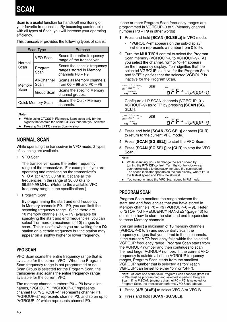
46
SCAN
Scan is a useful function for hands-off monitoring of your favorite frequencies. By becoming comfortable with all types of Scan, you will increase your operating efficiency.
This transceiver provides the following types of scans:
Scan Type Purpose
Normal Scan
VFO Scan Scans the entire frequency range of the transceiver.
Program Scan
Scans the specific frequency ranges stored in Memory channels P0 ~ P9.
Memory Scan
All-Channel Scan
Scans all Memory channels, from 00 ~ 99 and P0 ~ P9
Group Scan Scans the specific Memory channel groups.
Quick Memory Scan Scans the Quick Memory channels.
Note:◆ While using CTCSS in FM mode, Scan stops only for the
signals that contain the same CTCSS tone that you selected.◆ Pressing Mic [PTT] causes Scan to stop.
NORMAL SCANWhile operating the transceiver in VFO mode, 2 types of scanning are available.
• VFO Scan
The transceiver scans the entire frequency range of the transceiver. For example, if you are operating and receiving on the transceiver’s VFO A at 14.195.00 MHz, it scans all the frequencies in the range of 30.00 kHz to 59.999.99 MHz. (Refer to the available VFO frequency range in the specifications.)
• Program Scan
By programming the start and end frequency in Memory channels P0 ~ P9, you can limit the scanning frequency range. Since there are 10 memory channels (P0 ~ P9) available for specifying the start and end frequencies, you can select 1 or more (a maximum of 10) ranges to scan. This is useful when you are waiting for a DX station on a certain frequency but the station may appear on a slightly higher or lower frequency.
VFO SCANVFO Scan scans the entire frequency range that is available for the current VFO. When the Program Scan frequency range is not programmed or no Scan Group is selected for the Program Scan, the transceiver also scans the entire frequency range available for the current VFO.
The memory channel numbers P0 ~ P9 have alias names, “VGROUP”. “VGROUP–0” represents channel P0, “VGROUP–1” represents channel P1, “VGROUP–2” represents channel P2, and so on up to “VGROUP–9” which represents channel P9.
If one or more Program Scan frequency ranges are programmed in VGROUP–0 to 9 (Memory channel numbers P0 ~ P9 in other words):
1 Press and hold [SCAN (SG.SEL)] in VFO mode.
• “VGROUP–n” appears on the sub-display (where n represents a number from 0 to 9).
2 Turn the MULTI/CH control to select the Program Scan memory (VGROUP–0 to VGROUP–9). As you select the channel, “on” or “oFF” appears on the frequency display. “on” signifies that the selected VGROUP is active for the Program Scan and “oFF” signifies that the selected VGROUP is inactive for the Program Scan.
Configure all P.SCAN channels (VGROUP–0 ~ VGROUP–9) as “oFF” by pressing [SCAN (SG.SEL)].
3 Press and hold [SCAN (SG.SEL)] or press [CLR] to return to the current VFO mode.
4 Press [SCAN (SG.SEL)] to start the VFO Scan.
5 Press [SCAN (SG.SEL)] or [CLR] to stop the VFO Scan.
Note:◆ While scanning, you can change the scan speed by
turning the RIT/ XIT control. Turn the control clockwise/ counterclockwise to decrease/ increase the scan speed. The speed indicator appears on the sub-display, where P1 is the fastest speed and P9 is the slowest.
◆ You cannot change the VFO Scan speed in FM mode.
PROGRAM SCANProgram Scan monitors the range between the start and end frequencies that you have stored in Memory channels P0 ~ P9 (VGROUP–0 ~ 9). Refer to “STORING FREQUENCY RANGES” {page 43} for details on how to store the start and end frequencies to these Memory channels.
You can select a maximum of 10 memory channels (VGROUP–0 to 9) and sequentially scan the frequency ranges that you stored in these channels. If the current VFO frequency falls within the selected VGROUP frequency range, Program Scan starts from the VGROUP number and then continues to scan the next larger VGROUP number. If the current VFO frequency is outside all of the VGROUP frequency ranges, Program Scan starts from the smallest VGROUP number that is selected as “on” (each VGROUP can be set to either “on” or “oFF”).
Note: At least one of the valid Program Scan channels (from P0 to P9) must be programmed and selected to perform Program Scan. If no P.SCAN (memory channel P0 ~ P9) is selected for Program Scan, the transceiver performs VFO Scan {above}.
1 Press [A/B (A=B)] to select VFO A or VFO B.
2 Press and hold [SCAN (SG.SEL)].

47
11 SCAN
PROGRAM SCAN PARTIALLY SLOWEDYou can specify a maximum of 5 frequency points for each memory channel from P0 to P9 so that Program Scan slows down the scanning speed. To specify the slow down frequency points, first program the start and end frequencies into a memory channel (P0 ~ P9).
1 Access Menu No. 19 to confirm that the function is ON (default is ON).
2 You can further configure the slow down frequency width. Access Menu No. 20 to select the range from 100 Hz to 500 Hz (default is 300 Hz).
Note: If you select, for example, 500 Hz for Menu No. 20, the Program Scan slows down to a ±500 Hz width, centering the frequency you marked below.
3 Press [M/V], then turn the MULTI/CH control to recall the memory channel (P0 ~ P9) for which you want to specify the scan slow down frequencies.
4 Turn the Tuning control to the center frequency point that you want the Program Scan to slow down. Then, press [Q-M.IN] to mark the slow down frequency point.
• “ ” appears.
5 Repeat step 4 to specify the center slow down frequency points.
• You can specify a maximum of 5 frequency points for each channel.
6 If you want to clear a slow down frequency point that you previously stored, select the frequency that you stored, then press [Q-M.IN] at this frequency spot where “ ” appears.
• A confirmation beep sounds and “ ” disappears.
• To clear all slow down frequency points, press and hold [Q-M.IN].
7 Press [M/V] to return to VFO mode.
8 Press [SCAN (SG.SEL)] to start the Program Scan with the slow down frequency point(s).
Note:◆ During Program Scan, you can turn the RIT/ XIT control
to adjust the scanning speed. Turn the control clockwise/ counterclockwise to slow down/ speed up the scan. The Program Scan speed indicator appears on the main display during Program Scan; P1 is the fastest speed and P9 is the slowest.
◆ You cannot change the Program Scan speed in FM mode.◆ Although you can specify the Program Scan slow down
frequency point in FM mode, it does not function.◆ When copying a Program Memory Channel, all frequency
points are cleared.
3 Turn the MULTI/CH control or press Mic [UP]/ [DWN] to select the memory channel (VGROUP–0 to VGROUP–9). As you select the Memory Channel, “on” or “oFF” appears on the main frequency display. “on” signifies that the memory channel is active for the Program Scan and “oFF” signifies that the memory channel group is inactive for the Program Scan.
4 To activate the Program Scan frequency range, select the desired VGROUP number by turning the MULTI/CH control. Then, press [M.IN] to select “on” for the VGROUP (channel). When a channel is activated for Program Scan, “on” appears on the display.
5 Press and hold [SCAN (SG.SEL)] or press [CLR] to return to the current VFO mode.
6 Press [SCAN (SG.SEL)] to start the Program Scan.
• To quickly move toward a desired frequency while scanning, turn the Tuning control or the MULTI/CH control, or press Mic [UP]/ [DWN].
• Turning the RIT/ XIT control clockwise decreases the scan speed and counterclockwise increases the speed, except while in FM mode. The current scan speed is shown on the display; P1 is the fastest speed and P9 is the slowest.
• While in FM mode, Scan automatically stops on a frequency where a signal is present. The transceiver will either remain on that channel for a short time (Time-Operated mode) or until the signal drops out (Carrier-Operated mode), depending on which mode you select via Menu No. 22 {page 48}.
7 To stop Scan, press [SCAN (SG.SEL)] or [CLR].Note:◆ If you have turned the SQL control clockwise, far beyond the
squelch threshold while in FM mode, Scan may fail to stop at a channel where a signal is present. If this happens, turn the SQL control slightly counterclockwise.
◆ If you press [SCAN (SG.SEL)] before storing any frequency range for memory channels P0 to P9, the transceiver starts VFO scan.
◆ When the current receive frequency is within one of the ranges that you selected with channel numbers, Scan starts with the current frequency. The operating mode stored in the memory channel is used.
◆ The operating mode can be changed while scanning, but the memory channel will be overwritten with the changed mode.
◆ When the current Scan range is smaller than a single step of the MULTI/CH control, turning the control clockwise causes Scan to jump to the start frequency, and counterclockwise to the end frequency.
◆ Starting Program Scan switches OFF the RIT and XIT functions.
◆ While in FM mode, Program Scan monitors rounded off frequencies regardless of the Menu No. 12 setting.

48
11 SCAN
SCAN HOLDThis function stops Program Scan for approximately 5 seconds, then resumes Scan when you jump to the desired frequency by turning the Tuning control or the MULTI/CH control, or by pressing Mic [UP]/ [DWN].
To use this function, access Menu No. 21, and select “on”. The default is OFF.
MEMORY SCANMemory Scan monitors all memory channels in which you have stored frequencies (All-channel Scan) or only a desired group of memory channels (Group Scan).
Scan automatically stops at a channel where a signal is present, regardless of the operating mode. The transceiver will either remain on that channel for a short time (Time-Operated mode) or until the signal drops out (Carrier-Operated mode). Use Menu No. 22 to select the mode. The default is “to” (Time-Operated).
SCAN RESUMEThe transceiver stops scanning at the frequency (or memory channel) where a signal is detected. It then continues scanning according to which resume mode you have selected. You can choose one of the following modes. The default is Time-Operated mode.
• Time-Operated mode (“to”)
The transceiver remains on a busy frequency (or memory channel) for approximately 6 seconds, then continues to scan, even if the signal is still present.
• Carrier-Operated mode (“co”)
The transceiver remains on the busy frequency (or memory channel) until the signal drops out. There is a 2 second delay between signal dropout and scan resumption.
1 Press [MENU], then press [Q-M.IN]/ [Q-MR] or turn the MULTI/CH control to select Menu No. 22.
2 Press [M.IN]/ [SCAN (SG.SEL)] to select “to” (Time-Operated) or “co” (Carrier-Operated).
3 Press [MENU] to exit Menu mode.
You can lock out the memory channels that you prefer not to monitor while scanning (refer to “Memory Channel Lockout”).
ALL-CHANNEL SCANUse the following procedure to scan all the memory channels that contain frequency data in sequence, ignoring the Memory Group number.
1 Select Time-Operated or Carrier-Operated mode via Menu No. 22.
2 Press [M/V] to enter Memory Recall mode.
3 Turn the SQL control to adjust the squelch threshold to mute the speaker.
4 Press and hold [SCAN (SG.SEL)] to enter Scan Group Select mode.
• Turn the MULTI/CH control to select the Memory channel group.
• MGROUP–0 represents Memory channels 0 ~ 9, MGROUP–1 represents Memory channels 10 ~ 19 and so on up to MGROUP–9 which represents Memory channels 90 ~ 99 and MGROUP–P which represents Memory channels P0 ~ P9.
5 As you select the Memory Groups using the MULTI/CH control, press [M.IN] to select “on” for all Memory Groups.
6 Press and hold [SCAN (SG.SEL)] to return to Memory Recall mode.
7 Press [SCAN (SG.SEL)] to start All-channel Scan.
• Scan starts from the current memory channel and ascends up through the channel numbers. (The scan direction cannot be changed.)
• To jump to a desired channel while scanning, turn the MULTI/CH control, or press Mic [UP]/ [DWN].
8 To stop Scan, press [SCAN (SG.SEL)] or [CLR].Note:◆ If you have turned the SQL control clockwise, far beyond the
squelch threshold, Scan may fail to stop at a channel where a signal is present. If this happens, turn the SQL control slightly counterclockwise.
◆ Starting Memory Scan switches OFF the RIT and XIT functions.

49
11 SCAN
GROUP SCAN110 memory channels are divided into 11 groups so that you can select one or more groups to be scanned, depending on the situation.
■ Memory Group
When you store frequency data in a memory channel, the memory channel belongs to one of 11 groups as shown below.
MGROUP-0 Memory Channel Nos. 00 ~ 09
MGROUP-1 Memory Channel Nos. 10 ~ 19
MGROUP-2 Memory Channel Nos. 20 ~ 29
MGROUP-3 Memory Channel Nos. 30 ~ 39
MGROUP-4 Memory Channel Nos. 40 ~ 49
MGROUP-5 Memory Channel Nos. 50 ~ 59
MGROUP-6 Memory Channel Nos. 60 ~ 69
MGROUP-7 Memory Channel Nos. 70 ~ 79
MGROUP-8 Memory Channel Nos. 80 ~ 89
MGROUP-9 Memory Channel Nos. 90 ~ 99
MGROUP-P Memory Channel Nos. P0 ~ P9
■ Scan Group Select
You can select one or more groups to be scanned. First, select the groups to be scanned.
1 Press [M/V] to enter Memory Recall mode.
• “ ” appears.
2 Press and hold [SCAN (SG.SEL)] to enter Scan Group Select mode.
3 As you turn the MULTI/CH control, the MGROUP number on the sub-display changes.
• MGROUP–0 represents Memory channels 0 ~ 9, MGROUP–1 represents Memory channels 10 ~ 19 and so on up to MGROUP–9 which represents Memory channels 90 ~ 99 and MGROUP-P which represents Memory channels P0 ~ P9.
4 Press [M.IN] to select “on” to add the group to the Group Scan list.
• If you do not want to scan the selected Group, press [SCAN (SG.SEL)] to select “oFF”.
5 Press and hold [SCAN (SG.SEL)] or [CLR]. to exit the Scan Group Select mode.
■ Performing Group Scan
Group Scan starts with the smallest group number and repeats the sequence. For example, if you selected “on” for MGROUP–3, MGROUP–5, and MGROUP–7, the transceiver scans the channels in MGROUP–3 > MGROUP–5 > MGROUP–7 > MGROUP–3 and so on.
1 Select Time-Operated or Carrier-Operated mode via Menu No. 22.
2 Press [M/V] to enter Memory Recall mode.
3 Turn the SQL control to adjust the squelch threshold.
4 Press [SCAN (SG.SEL] to start Memory Group Scan.
• Scan ascends up through the channel numbers. (The scan direction cannot be changed.)
• To jump to a desired channel while scanning, turn the MULTI/CH control or press and hold Mic [UP]/ [DWN].
5 To stop Scan, press [SCAN (SG.SEL)] or [CLR].
Note:◆ If you have turned the SQL control clockwise, far beyond
the squelch threshold, Scan may fail to stop at a channel in which a signal is present. If this happens, turn the SQL control slightly counterclockwise.
◆ When the current channel is within one of the groups that you selected, Scan starts with the current channel.
◆ When the current channel is outside all the groups that you selected, Scan starts with the group number that is larger than and closest to the group number of the current channel.
◆ Starting Memory Scan switches OFF the RIT and XIT functions.
QUICK MEMORY SCAN1 Press [Q-MR] to enter Quick Memory mode.
2 Press [SCAN (SG.SEL] to start Quick Memory Scan.
• Scan starts from the current quick memory channel and ascends up through the channel numbers. (The scan direction cannot be changed.)
3 To stop Scan, press [SCAN (SG.SEL)] or [CLR].

50
OPERATOR CONVENIENCES
Note:◆ The APO function works even if the transceiver is scanning.◆ The APO timer starts counting down when no key presses,
no control adjustments, and no command (COM connector) sequences are detected.
AUTOMATIC ANTENNA TUNERAs explained in “ANTENNA CONNECTION” {page 1}, matching the impedance of the coaxial cable and antenna is important. To adjust the impedance between the antenna and the transceiver, you have the choice of using the internal antenna tuner or an external antenna tuner. This section describes how to use the internal antenna tuner. For the external antenna tuner, consult the instruction manual that comes with the tuner.
1 Select the transmit frequency.
2 Press and hold [PRE (ANT 1/2)] to select “ ” or “ ”.
• If the external antenna tuner (AT-300) is connected to the ANT 1 connector, select ANT 2 to use the internal antenna tuner. The internal antenna tuner is automatically bypassed if the external antenna tuner is connected to ANT 1.
3 Press and hold [AT (TUNE)].
• CW mode is automatically selected and tuning begins.
• “ ” blinks and the TX-RX LED lights red.
• To cancel tuning, press [AT (TUNE)] again.
• If the SWR of the antenna system is extremely high (more than 10:1), an alarm (“SWR” in Morse code) sounds and the internal antenna tuner is bypassed. Before attempting to tune again, adjust the antenna system to lower the SWR.
4 Monitor the display and check that tuning has successfully finished.
• If the tuning was successful, “ ” stops blinking and the red TX-RX LED turns OFF.
• If tuning does not finish within approximately 20 seconds, an alarm (“5” in Morse code) sounds. Press [AT (TUNE)] to stop the alarm and tuning.
• If you want the transceiver to stay in transmission mode after the tuning completes, access Menu No. 51 and select “on”.
• To pass received signals through the internal antenna tuner, access Menu No. 52 and select “on”. When this function is ON, “ ” appears. This may reduce interference on the receive frequency.
ANTENNAS
ANT 1/ ANT 2Two antenna connectors are available for the HF/ 50 MHz band on the TX/ RX unit rear panel.
Press and hold [PRE (ANT 1/2)] to select ANT 1 or ANT 2.
• “ ” or “ ” appears to indicate which antenna is selected.
RX ANTPress and hold [ATT (RX ANT)] to toggle the RX ANT between enabled and disabled.
• “ ” appears when the RX ANT is enabled.
DRVPress and hold [METER (DRV)] to switch the DRV between enabled and disabled.
Use the standard input of 1 mW for the linear amplifier and other connections.
• “ ” appears when the DRV is enabled
The ANT 1, ANT 2, RX ANT, and DRV settings will automatically be stored in the antenna band memory. The next time you select the same band, the same antenna will be automatically selected.
Antenna Selection Frequency Range (MHz)
0.03 ~ 0.522 10.5 ~ 14.5
0.522 ~ 2.5 14.5 ~ 18.5
2.5 ~ 4.1 18.5 ~ 21.5
4.1 ~ 6.9 21.5 ~ 25.5
6.9 ~ 7.5 25.5 ~ 30.0
7.5 ~ 10.5 30.0 ~ 60.0
Note:◆ Connect an external tuner to the ANT 1 connector only,
then select ANT 1. The internal antenna tuner will be automatically bypassed when the transceiver is switched ON.
◆ The RX ANT can be used with less than 30 MHz.
APO (Auto Power OFF)You can set the transceiver to switch OFF automatically if no keys or controls are pressed or adjusted for a certain period of time. One minute before the transceiver switches OFF, “CHECK” is output in Morse code.
1 Press [MENU], then press [Q-M.IN]/ [Q-MR] or turn the MULTI/CH control to access Menu No. 78.
2 Press [M.IN]/ [SCAN (SG.SEL)] to select the APO time from “oFF”, “60”, “120”, or “180” minutes.
3 Press [MENU] to exit Menu mode.

51
12 OPERATOR CONVENIENCES
Note:◆ The internal antenna tuner will not tune outside the available
transmission frequency limits.◆ Pressing [AT (TUNE)] for more than 1 second while
transmitting interrupts transmitting and starts tuning.◆ While using CW Full Break-in, the internal antenna tuner will
be in-line for both transmission and reception.◆ Tuning automatically turns OFF in approximately 60
seconds. “AT” disappears and the error beeps stop.◆ Tuning may still continue when the SWR meter indicates
1:1. This happens due to the tuning algorithm; this is not a malfunction.
◆ Even though the SWR meter shows more than one segment, the internal antenna tuner may not re-tune. This happens because of an SWR calculation algorithm tolerance.
◆ If tuning does not finish even though the SWR meter indicates smaller than 3:1, adjust the antenna system to lower the SWR, then attempt to tune again.
◆ Tuning may not reach an SWR of 1:1, depending on the transceiver conditions.
◆ The AT-300 cannot perform tuning on the 50 MHz band.
PRESETTINGAfter each successful tuning session, the internal antenna tuner Preset memory function stores the position of the tuning capacitor in memory. The position of the capacitor is stored for each of the antenna tuner bands (see the following table) and for each antenna connector (ANT 1 and ANT 2).
Press [AT (TUNE)].
• “ ” or “ ”appears, showing that the antenna tuner is in-line (not bypassed).
• Each time you go across the antenna tuner band, the internal antenna tuner Preset memory is automatically recalled to position the tuning capacitor without the need for retuning. If no preset data exists for a particular band/ antenna combination, then the default data of 50 Ω is used.
Note: Tuning may restart in order to obtain the optimum matching condition even though the current antenna tuner band has the preset data.
Internal Antenna Tuner Preset Frequency Range (MHz)
0.03 ~ 1.85 14.1 ~ 14.5
1.85 ~ 2.50 14.5 ~ 18.5
2.50 ~ 3.525 18.5 ~ 21.15
3.525 ~ 3.575 21.15 ~ 21.5
3.575 ~ 3.725 21.5 ~ 25.5
3.725 ~ 4.1 25.5 ~ 29.0
4.1 ~ 6.9 29.0 ~ 30.0
6.9 ~ 7.05 30.0 ~ 51.0
7.05 ~ 7.1 51.0 ~ 52.0
7.1 ~ 7.5 52.0 ~ 53.0
7.5 ~ 10.5 53.0 ~ 60.0
10.5 ~ 14.1
AUTO MODEYou can configure a maximum of 32 frequency borders (VFO A and B) to change the operating mode automatically as you change the VFO frequency.
As a default, the following modes are programmed on each operating band.
0.03 MHz ~ 9.5 MHz: LSB
9.5 MHz ~ 60 MHz: USB
To add the frequency borders to the Auto Mode selection:
1 With the transceiver power OFF, press and hold [LSB/USB] + [ ] to turn the transceiver ON.
• “AUTOMODE” appears on the sub-display.
2 Select an Auto Mode frequency memory channel number by turning the MULTI/CH control.
• Auto Memory channels 00 to 31 are available.
3 Turn the Tuning control to select a desired frequency border (or enter the frequency with the keypad {page 28}) to change the operating mode.
4 Press [LSB/USB], [CW/FSK (REV)], [FM/AM (FM-N)], or [DATA] until the desired communication mode appears.
5 Repeat steps 2 ~ 4 until you have added all the data.
6 Press [CLR] to exit the Auto Mode frequency configuration.
To activate the Auto Mode function:
1 Press [MENU], then press [Q-M.IN]/ [Q-MR] or turn the MULTI/CH control to select Menu No. 23.
2 Press [M.IN] to select “on”.
3 Press [MENU] to exit Menu mode.Note: When using Auto Mode Frequency configuration, you cannot use the Frequency Entry History function.

52
12 OPERATOR CONVENIENCES
BEEP FUNCTIONThe Beep function provides you confirmation of entry, error status, and malfunctions of the transceiver.
Although you can turn the beep function OFF by accessing Menu No. 03, we recommend you leave it ON in order to detect unexpected errors and malfunctions. You can also change the output level of the beeps by accessing Menu No. 03 and selecting “1” to “9”.
The transceiver generates the following Morse code to tell you which mode is selected when you change operating modes:
Mode Morse Code Output
USB • • – (U)
LSB • – • • (L)
CW – • – • (C)
FSK • – • (R)
AM • – (A)
FM • • – • (F)
USB-DATA • • – – • • (UD)
LSB-DATA • – • • – • • (LD)
CW-R – • – • • – • (CR)
FSK-R • – • • – • (RR)
FM-NAR • • – • – • (FN)
FM-DATA • • – • – • • (FD)
FM-NAR-DATA • • – • – • – • • (FND)
The transceiver also generates the following warning, confirmation, and malfunction beeps.
Beep Type Meaning
Short, high pitch A valid key is pressed.
Double, high pitch A secondary function is selected.
3 times, high pitch The third function is accepted.
Long, high pitch A key entry is accepted, Scan starts, or AT tune has completed.
Short, regular A function is turned OFF.
Short, low pitch An invalid key is pressed.
Morse “UL” The internal PLL circuit unlock status is detected.
Morse “S” CW Auto Tune cannot complete, or an invalid frequency is entered.
Morse “5” AT Tune cannot be completed within the specified time.
Morse “SWR” The antenna’s SWR is too high (over 10:1) to perform AT tune.
Morse “CHECK”
1 minute before the APO (Auto Power Off) function switches the transceiver OFF, a protection circuit is ON. or an invalid voltage is detected.
Morse “BT” Waiting for a CW message to be recorded.
Morse “AR” The current message memory is full.
The table below is an example of setting the Auto Mode frequency.
Channel No.
Frequency (MHz) Mode Operation Range
(MHz)
00 1.620 AM 0.030 ≤ f < 1.620
01 2.000 CW 1.620 ≤ f < 2.000
02 3.500 LSB 2.000 ≤ f < 3.500
03 3.525 CW 3.500 ≤ f < 3.525
04 10.100 LSB 3.525 ≤ f < 10.100
05 10.150 CW 10.100 ≤ f < 10.150
06 14.000 USB 10.150 ≤ f < 14.000
07 14.070 CW-R 14.000 ≤ f < 14.070
08 14.112 FSK 14.070 ≤ f < 14.112
09 18.068 USB 14.112 ≤ f < 18.068
10 18.110 CW 18.068 ≤ f < 18.110
11 21.000 USB 18.110 ≤ f < 21.000
12 21.070 CW 21.000 ≤ f < 21.070
13 21.125 FSK-R 21.070 ≤ f < 21.125
14 21.150 CW 21.125 ≤ f < 21.150
15 24.890 USB 21.150 ≤ f < 24.890
16 24.930 CW 24.890 ≤ f < 24.930
17 28.000 USB 24.930 ≤ f < 28.000
18 28.070 CW 28.000 ≤ f < 28.070
19 28.150 FSK 28.070 ≤ f < 28.150
20 28.200 CW 28.150 ≤ f < 28.200
21 29.000 USB 28.200 ≤ f < 29.000
22 30.000 FM-DATA 29.000 ≤ f < 30.000
23 50.000 USB 30.000 ≤ f < 50.000
24 50.100 CW 50.000 ≤ f < 50.100
25 51.000 USB 50.100 ≤ f < 51.000
26 52.000 FM 51.000 ≤ f < 52.000
27 52.000 LSB
28 52.000 LSB
29 52.000 LSB
30 52.000 LSB
31 52.000 LSB
• The frequencies for channels 27 ~ 31 have not been configured, but because they are the same frequency as channel 26, they will be FM mode 51.0 MHz ≤ f < 52.0 MHz.
• Since the frequencies above 52.0 MHz have not been configured, they will be USB mode 52.0 MHz ≤ f < 60.0 MHz
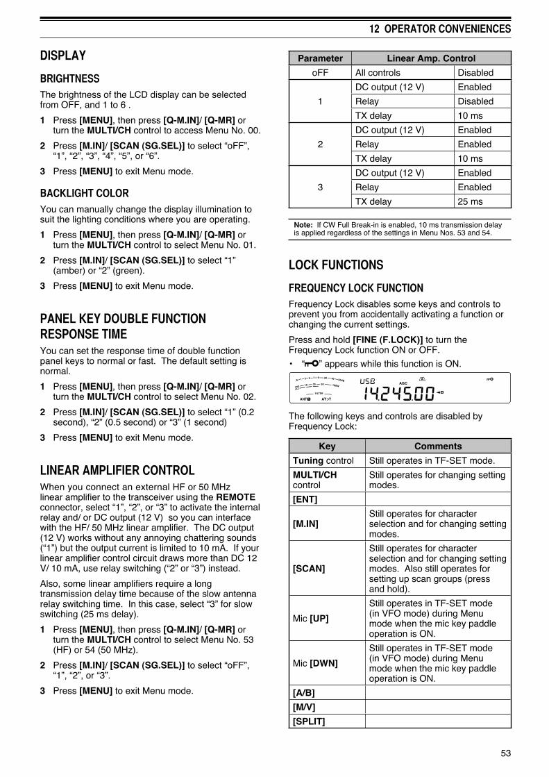
53
12 OPERATOR CONVENIENCES
DISPLAY
BRIGHTNESSThe brightness of the LCD display can be selected from OFF, and 1 to 6 .
1 Press [MENU], then press [Q-M.IN]/ [Q-MR] or turn the MULTI/CH control to access Menu No. 00.
2 Press [M.IN]/ [SCAN (SG.SEL)] to select “oFF”, “1”, “2”, “3”, “4”, “5”, or “6”.
3 Press [MENU] to exit Menu mode.
BACKLIGHT COLORYou can manually change the display illumination to suit the lighting conditions where you are operating.
1 Press [MENU], then press [Q-M.IN]/ [Q-MR] or turn the MULTI/CH control to select Menu No. 01.
2 Press [M.IN]/ [SCAN (SG.SEL)] to select “1” (amber) or “2” (green).
3 Press [MENU] to exit Menu mode.
PANEL KEY DOUBLE FUNCTION RESPONSE TIMEYou can set the response time of double function panel keys to normal or fast. The default setting is normal.
1 Press [MENU], then press [Q-M.IN]/ [Q-MR] or turn the MULTI/CH control to select Menu No. 02.
2 Press [M.IN]/ [SCAN (SG.SEL)] to select “1” (0.2 second), “2” (0.5 second) or “3” (1 second)
3 Press [MENU] to exit Menu mode.
LINEAR AMPLIFIER CONTROLWhen you connect an external HF or 50 MHz linear amplifier to the transceiver using the REMOTE connector, select “1”, “2”, or “3” to activate the internal relay and/ or DC output (12 V) so you can interface with the HF/ 50 MHz linear amplifier. The DC output (12 V) works without any annoying chattering sounds (“1”) but the output current is limited to 10 mA. If your linear amplifier control circuit draws more than DC 12 V/ 10 mA, use relay switching (“2” or “3”) instead.
Also, some linear amplifiers require a long transmission delay time because of the slow antenna relay switching time. In this case, select “3” for slow switching (25 ms delay).
1 Press [MENU], then press [Q-M.IN]/ [Q-MR] or turn the MULTI/CH control to select Menu No. 53 (HF) or 54 (50 MHz).
2 Press [M.IN]/ [SCAN (SG.SEL)] to select “oFF”, “1”, “2”, or “3”.
3 Press [MENU] to exit Menu mode.
Parameter Linear Amp. Control
oFF All controls Disabled
1
DC output (12 V) Enabled
Relay Disabled
TX delay 10 ms
2
DC output (12 V) Enabled
Relay Enabled
TX delay 10 ms
3
DC output (12 V) Enabled
Relay Enabled
TX delay 25 ms
Note: If CW Full Break-in is enabled, 10 ms transmission delay is applied regardless of the settings in Menu Nos. 53 and 54.
LOCK FUNCTIONS
FREQUENCY LOCK FUNCTIONFrequency Lock disables some keys and controls to prevent you from accidentally activating a function or changing the current settings.
Press and hold [FINE (F.LOCK)] to turn the Frequency Lock function ON or OFF.
• “ ” appears while this function is ON.
The following keys and controls are disabled by Frequency Lock:
Key Comments
Tuning control Still operates in TF-SET mode.
MULTI/CH control
Still operates for changing setting modes.
[ENT]
[M.IN]Still operates for character selection and for changing setting modes.
[SCAN]
Still operates for character selection and for changing setting modes. Also still operates for setting up scan groups (press and hold).
Mic [UP]
Still operates in TF-SET mode (in VFO mode) during Menu mode when the mic key paddle operation is ON.
Mic [DWN]
Still operates in TF-SET mode (in VFO mode) during Menu mode when the mic key paddle operation is ON.
[A/B]
[M/V]
[SPLIT]
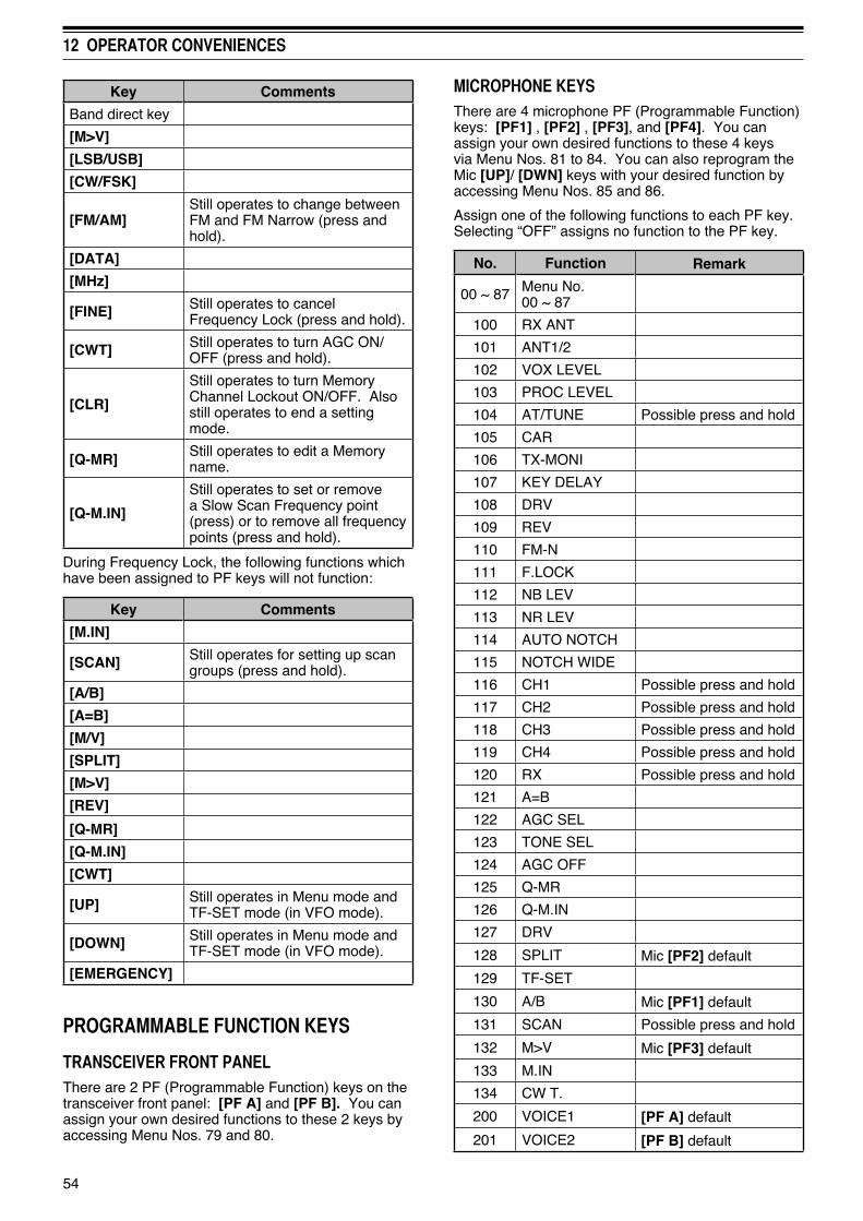
54
12 OPERATOR CONVENIENCES
Key Comments
Band direct key
[M>V]
[LSB/USB]
[CW/FSK]
[FM/AM]Still operates to change between FM and FM Narrow (press and hold).
[DATA]
[MHz]
[FINE] Still operates to cancel Frequency Lock (press and hold).
[CWT] Still operates to turn AGC ON/OFF (press and hold).
[CLR]
Still operates to turn Memory Channel Lockout ON/OFF. Also still operates to end a setting mode.
[Q-MR] Still operates to edit a Memory name.
[Q-M.IN]
Still operates to set or remove a Slow Scan Frequency point (press) or to remove all frequency points (press and hold).
During Frequency Lock, the following functions which have been assigned to PF keys will not function:
Key Comments
[M.IN]
[SCAN] Still operates for setting up scan groups (press and hold).
[A/B]
[A=B]
[M/V]
[SPLIT]
[M>V]
[REV]
[Q-MR]
[Q-M.IN]
[CWT]
[UP] Still operates in Menu mode and TF-SET mode (in VFO mode).
[DOWN] Still operates in Menu mode and TF-SET mode (in VFO mode).
[EMERGENCY]
PROGRAMMABLE FUNCTION KEYS
TRANSCEIVER FRONT PANELThere are 2 PF (Programmable Function) keys on the transceiver front panel: [PF A] and [PF B]. You can assign your own desired functions to these 2 keys by accessing Menu Nos. 79 and 80.
MICROPHONE KEYSThere are 4 microphone PF (Programmable Function) keys: [PF1] , [PF2] , [PF3], and [PF4]. You can assign your own desired functions to these 4 keys via Menu Nos. 81 to 84. You can also reprogram the Mic [UP]/ [DWN] keys with your desired function by accessing Menu Nos. 85 and 86.
Assign one of the following functions to each PF key. Selecting “OFF” assigns no function to the PF key.
No. Function Remark
00 ~ 87 Menu No. 00 ~ 87
100 RX ANT
101 ANT1/2
102 VOX LEVEL
103 PROC LEVEL
104 AT/TUNE Possible press and hold
105 CAR
106 TX-MONI
107 KEY DELAY
108 DRV
109 REV
110 FM-N
111 F.LOCK
112 NB LEV
113 NR LEV
114 AUTO NOTCH
115 NOTCH WIDE
116 CH1 Possible press and hold
117 CH2 Possible press and hold
118 CH3 Possible press and hold
119 CH4 Possible press and hold
120 RX Possible press and hold
121 A=B
122 AGC SEL
123 TONE SEL
124 AGC OFF
125 Q-MR
126 Q-M.IN
127 DRV
128 SPLIT Mic [PF2] default
129 TF-SET
130 A/B Mic [PF1] default
131 SCAN Possible press and hold
132 M>V Mic [PF3] default
133 M.IN
134 CW T.
200 VOICE1 [PF A] default
201 VOICE2 [PF B] default

55
12 OPERATOR CONVENIENCES
RX MONITORRX monitor temporarily disables the squelch function to monitor the current frequency activities.
To use the RX Monitor function, first assign the function to a PF key (either on the front panel or the microphone).
1 Press [MENU], then press [Q-M.IN]/ [Q-MR] or turn the MULTI/CH control to select Menu No. 79 ~ 86.
2 Press [M.IN]/ [SCAN (SG.SEL)] to select “203”.
3 Press [MENU] to exit Menu mode.
4 Press the assigned [PF] key.
• While pressing [PF], the speaker unmutes.
TIME-OUT TIMERThe Time-out Timer limits the time of each transmission. It is also useful to prevent a long accidental transmission.
1 Press [MENU], then press [Q-M.IN]/ [Q-MR] or turn the MULTI/CH control to access Menu No. 49.
2 Press [M.IN]/ [SCAN (SG.SEL)] to select “oFF”, “3”, “5”, “10”, “20”, or “30” minutes.
3 Press [MENU] to exit Menu mode.
TRANSVERTERIf you have a transverter that converts the TS-590S operating frequencies to other frequencies, you can use this TS-590S transceiver as a transverter exciter. Consult the instruction manual that came with the transverter for interfacing to the TS-590S transceiver.
FREQUENCY DISPLAY1 Connect the transverter to the ANT 1, ANT 2, RX
ANT, or DRV connector of the TS-590S.
2 Select the exciter operating frequency on the transceiver.
• The transverter will use this frequency as the reference for converting frequencies.
3 Press [MENU], then press [Q-M.IN]/ [Q-MR] or turn the MULTI/CH control to access Menu No. 50.
4 Press [M.IN]/ [SCAN (SG.SEL)] to select “1”.
• The output power is automatically set to the lowest power for that frequency (default). Refer to “TX POWER” {below}.
5 Press [MENU] to exit Menu mode.
6 Press [ENT], then set the target converting frequency using the numeric keys.
7 Press [ENT] to complete the entry.
• The transceiver displays the target transverter frequency instead of the actual operating frequency.
No. Function Remark
202 VOICE3 The lower meter when transmitting
203 MONITOR Mic [PF4] default
204 TX TUNE
205 DATA SENDThe input voice from the data terminal is transmitted
206 DOWN Mic [DWN] default
207 UP Mic [UP] default
208 EMERGENCY Emergency frequency call (K type only)
OFF No function
Note:◆ Assigned key functions may not work, depending on the
setting.◆ [AGC SEL] can be used in modes other than FM mode,
and can set a step level of the chosen AGC time constant (FAST/ SLOW).
◆ [TONE SEL] can also be used in FM mode while TONE or CTCSS is ON,
DSP RX EQUALIZER
EQUALIZING RECEIVING AUDIOUse Menu No. 31 to change the receiver frequency responses of the target signal. You can select one from 8 different receiver profiles including the default flat response. Selecting any of the following items from the Menu causes “ ” to appear on the display.
• Off (oFF):Slightly attenuates (1 kHz or higher audio frequencies).
• High boost 1 (hb1):Emphasizes higher audio frequencies.
• High boost 2 (hb2):Emphasizes higher audio frequencies but lower audio frequency attenuation is less than High boost1 (hb1).
• Formant pass (FP):Improves clarity by suppressing audio frequencies outside the normal voice frequency range.
• Bass boost 1 (bb1):Emphasizes lower audio frequencies.
• Bass boost 2 (bb2):Emphasizes lower audio frequencies but higher audio frequency attenuation is less than Bass boost1 (bb1).
• Flat (FLAT):The flat frequency response.
• User (U):Reserved for the ARCP software. Off is programmed at the factory as a default.

56
12 OPERATOR CONVENIENCES
Note:◆ When using a transverter, not all the functions of this
transceiver are available.◆ When turning the transverter ON, the frequency entry history
is cleared, thus you cannot use the frequency entry history function.
◆ When using an antenna tuner in the IN state and the transverter is turned ON, the antenna tuner is forced to the THRU state.
TRANSMISSION OUTPUT POWERIf Menu No. 50 is set to “1” {above}, the transceiver automatically decreases the output power to 5 watts. However, if you do not wish to decrease the output power, access Menu No. 50 and select “2”; the transceiver will transmit at full power.
Note: You are responsible for your transmission output power settings.
TX MONITORTX monitor allows you to monitor the on-going transmission sound. This is convenient when you want to check the modulation sound quality of the transmission. In FSK mode, you can monitor the FSK signal that the transceiver is transmitting.
1 Press and hold [PWR (TX MONI)].
• The current TX monitor setting appears on the sub-display.
2 Turn the MULTI/CH control to select the monitor sound level from “oFF”, and “1” to “9”.
3 Press [CLR] to store the selected TX monitor level.Note:◆ We recommend you use headphones when you monitor
SSB, AM, or FM mode, in order to avoid howling.◆ The CW transmission signal cannot be monitored using
the TX monitor function. Use the TX sidetone function to monitor CW transmissions (Menu Nos. 04 and 34).
TX POWERYou can adjust the transmission output power by pressing [PWR (TX MONI)] and turning the MULTI/CH control. If more precise power adjustment is required, access Menu No. 48 and select “on”. When this function is activated, the power adjustment steps change as shown in the table below.
Mode Menu No. 48 OFF Menu No. 48 ON
SSB/ CW/ FM/ FSK
5 ~ 100 Win steps of 5
5 ~ 100 Win steps of 1
AM 5 ~ 25 Win steps of 5
5 ~ 25 Win steps of 1
Note: The output power settings are stored independently for HF and 50 MHz. As shown in the table above, you can also store different output power settings for AM and other modes for HF bands and the 50 MHz band.
TX TUNEThe TX Tune function allows you to adjust the antenna length, or tune the linear amplifier while transmitting a continuous CW signal.
To use the TX Tune function, first assign the function to a PF key (either the front panel or Microphone PF keys).
1 Press [MENU], then press [Q-M.IN]/ [Q-MR] or turn the MULTI/CH control to select a Menu No. from 79 to 86.
2 Press [M.IN]/ [SCAN (SG.SEL)] to select “204”.
3 Press [MENU] to exit Menu mode.
4 Press the assigned [PF] key.
• The transceiver automatically switches to CW mode, and transmits a continuous carrier. The transceiver selects the SWR meter function automatically.
• While in TX Tune mode, most keys are disabled.
• The default output power is configured as 10 watts. However, you can adjust the output power using [PWR (TX MONI)] and the MULTI/CH control if necessary. The transceiver stores the new output power setting when you exit the TX Tune mode.
5 Press the assigned [PF] key again to exit the TX Tune mode.
QUICK DATA TRANSFERThis transceiver has the capability to quickly and conveniently transfer the reception frequency and mode to another compatible transceiver. Compatible transceivers include:
TS-590S TS-480HX/ SAT TS-2000/X
TS-570S/ 570D TS-870S
Data transfer could be useful while contesting. A spotting station that is searching for new contest multipliers can quickly transfer a frequency over to the running (main) station.
SETTING UP
■ Equipment Needed
In addition to a compatible transceiver, to transfer to a TS-590S, TS-480HX/ SAT, TS-2000/X, TS-570S/D, or TS-870S, you must have 1 cross-wired cable with a DB-9 female connector at both ends.
■ Connections
For diagrams on how to connect the 2 transceivers, refer to “CONNECTING PERIPHERAL EQUIPMENT” {page 65}.

57
12 OPERATOR CONVENIENCES
COMPUTER CONTROLBy connecting this transceiver to a computer, you can change the computer into an electronic console from which you can remotely control functions of the transceiver. This capability makes remote operation of your transceiver possible from across the room, from another room, or when coupled with other commercially available products and where lawful, from another city, state, or country via an internet connection.
SETTING UP
■ Equipment Needed
When connecting the TS-590S to a PC USB port:
• USB 2.0 conformed (base) port
• Commercially available AB type USB 2.0 cable
• Transceiver control application
• Pre-installed virtual COM port driver, on the PC. (The driver is available at the website listed below.)
When connecting the TS-590S to a PC COM port:
• A PC equipped with a COM (serial) port
• 1 straight cable. This cable must have a DB-9 female connector at one end, and a DB-9 or a DB-25 female connector that mates with the COM port of your computer at the other end.
• Transceiver control application
To create your programs, access the Kenwood website and download the TS-590S command reference documents (pdf format) for details:
http://www.kenwood.com/i/products/info/amateur/software_download.html
■ Connections
To connect the transceiver to a computer, refer to the diagram in “CONNECTING PERIPHERAL EQUIPMENT” {page 65}.
Note: Before connecting this transceiver to a computer, switch OFF the power to both the transceiver and the computer.
COMMUNICATION PARAMETERSIn order to control the transceiver with the computer, you must first choose the communication parameters.
1 On the computer, configure your transceiver control application for 8 data bits, 1 stop bit, and no parity.
2 On the transceiver, select the same transfer rate via Menu No. 61 (COM port) or 62 (USB port).
• The defaults are 9600 bps and 1 stop bit for Menu No. 61 and 115200 bps and 1 stop bit for Menu No. 62.
• Only a baud rate of 4800 bps uses 2 stop bits.
3 Press [MENU] to exit Menu mode.
4 Turn the power OFF and then back ON to implement the change.
USING QUICK TRANSFERWhen connecting with another TS-590S, TS-480HX/ SAT, TS-2000/X, TS-570S/D/SG/DG, or TS-870S, use the same COM connector baud rate on each transceiver.
Note: While transferring data, other functions may work slower.
■ Transferring Data
The TS-590S transceiver works as the Master, sending data to the Slave transceiver.
1 Turn ON the Transfer function of each transceiver.
• On the TS-590S, access Menu No. 58 and select “on”. For the compatible transceiver, refer to the instruction manual that came with the transceiver.
2 On the Master, while in VFO mode, select an operating frequency and mode.
3 On the Master, press [Q-M.IN].
• The displayed data is stored in Quick Memory channel 0 on the Master and transferred to the Slave.
Note: If the Master has RIT switched ON, the offset frequency is added to the reception frequency to be transferred.
■ Receiving Data
The TS-590S transceiver works as the Slave, receiving data from the Master transceiver. The Slave can receive data using either Quick Memory channel 0 or the VFO.
1 Switch ON the Transfer function of each transceiver.
• On the TS-590S, access Menu No. 58 and select “on”. For the compatible transceiver, refer to the instruction manual that came with the transceiver.
2 On the Slave, access Menu No. 59 and select either “oFF” (QUICK MEMO channel 0) or “on” (the VFO).
• The default is OFF (QUICK MEMO).
3 On the Master, perform the appropriate operation to send data.
• For the correct method, refer to the instruction manual that came with the transceiver.
Note:◆ If you always use the TS-590S for receiving only,
activate the TX Inhibit function via Menu No. 60, to avoid unintentional transmission.
◆ When the Slave receives data using the VFO programmed with a simplex frequency, the received data replaces the data on both VFOs. On the Slave, both RIT and XIT are set to OFF.
◆ When the Slave receives data using the VFOs programmed with split frequencies, the received data replaces the data only on the TX side of the VFO. On the Slave, XIT is set to OFF but RIT is not changed.

58
12 OPERATOR CONVENIENCES
• When not using the USB terminal, besides a serial cable, create and connect a sound input/output cable. In this case when connecting to sound equipment and the audio output level is too high, change the level setting in Menu No. 66.
CONTROLLING THE TS-590S FROM A PCIf a PC and the TS-590S are connected using a serial cable {page 67}, you can remotely control the functions of the TS-590S from a PC. Download the free ARCP-590 software from the following URL:
http://www.kenwood.com/i/products/info/amateur/software _download.html
The detailed remote controlling instructions are available in accompanied documents and help file.
REMOTELY CONTROLLING THE TS-590S ON THE NETWORKIn addition to the ARCP-590 program, the ARHP-590 program can also be downloaded from the above site. This ARHP-590 program is an ARCP-590 host program that allows a user who is connected in the network to remotely control the TS-590S transceiver from a distant location. If you make interface cables that transfer the audio between the TS-590S transceiver and the PC on the host transceiver, you can receive signals and transmit your voice over the network. For detailed information, download the ARHP-590 program and consult the accompanied documents.
Note: The ARHP-590 does not support voice communication. In order to use voice communications, you must also use universal VoIP software.
OPTIONAL VGS-1 VOICE GUIDE & STORAGE UNITThe optional VGS-1 unit allows you to record 30 second (maximum) voice messages to memory channels 1 and 2, and 15 second (maximum) voice messages to memory channels 3 and 4. After recording a message via your transceiver microphone, you can then transmit those recorded messages. It also announces the key function and frequencies each time you press a key (Voice announcement). Since the incoming reception signal is processed in digital data in the transceiver, the VGS-1 can be configured to constantly store the incoming audio signals in the background. If you wish, you can store the last 30 seconds of the incoming signal to the VGS-1 for the later playback (Constant recording).
For information on how to install the VGS-1 unit, refer to “INSTALLING OPTIONS” {page 71}.
RECORDING MESSAGESThis section explains how to record a single message.
1 Select SSB, FM, or AM mode.
• Select a mode that you wish to transmit.
2 Press and hold [CH1 (REC)] to record the message for channel 1.
EXTERNAL AUDIO SETTINGS
■ Selecting a Data Transmission Line
Depending on how you connect your transceiver to a PC, you will need to set a data transmission line type. Access Menu No. 63 and select “ACC2” (default) or “USB”.
■ Audio Level Settings
You can set the input and output audio levels of an ACC2 connection via Menu Nos. 66 and 67, and the input and output audio levels of a USB connection via Menu Nos. 64 and 65. Each setting has a range of 0 to 9, with a default setting of 4.
Additionally, you can mix beep tones, the sidetone, and the Voice guide for an ACC2/USB audio output by accessing Menu No. 68 and selecting “on” (whereby the PC will confirm the sounds being output from the transceiver speaker).
CHANGING THE SIGNAL FOR THE COM TERMINALSend the PSQ (SQL control signal) and PKS signal through the COM terminal.
1 Turn the transceiver power OFF.
2 Press [FM/AM (FM-N)] + [ ].
• “PSQ/PKS” momentarily appears, and the RTS/CTS signal is replaced with the PSQ/PKS signal at the COM terminal.
3 Repeat steps 1 and 2 to return to normal operation.
• “CTS/RTS” momentarily appears.
The operation of the output signal for each setting is as follows:
COM Terminal PC
CTS/RTS
TxD RxD
RxD TxD
RTS CTS
CTS RTS
GND GND
PSQ/PKS
TxD (stopped) RxD
RxD (stopped) TxD
PSQ CTS
PKS RTS
GND GND
Normal PC commands (ARCP, ARHP, or SKY COMMAND SYSTEM II) will not work when this function is turned ON.
• When operating the TS-590S as a base station, using VoIP or similar software, set Menu No. 77 to “SQL”.
At the same time, if you are using CTCSS, set Menu No 75 to “2” and confirm that the frequency is not already in use and is not causing any interference.
• When turning the power OFF and the VoIP software misdetects a busy signal, set Menu No. 76 to “OPEN”.

59
12 OPERATOR CONVENIENCES
• BT in Morse code sounds and “AP 1 –” appears.
• To quit recording your message, press [CLR].
3 Press [MIC (CAR)], then rotate the MULTI/CH control to adjust the microphone gain so that the voice input level is not beyond the ALC level zone.
4 Hold [CH1 (REC)] and speak into your microphone.
• Four channels are available for recording messages. Press [CH2 (REC)], [CH3 (REC)], or [RX/4 (REC)] in place of [CH1 (REC)], in steps 3 and 4 to record the message on a different channel.
• If Constant Recording is active, [RX/4 (REC)] is unavailable for message recording.
5 Release the key when you have finished recording your message.
• When the maximum recording time passes, recording automatically stops.
• The contents of the channel is overwritten with the new message.
• “WRITING” appears while the transceiver is storing the message data to the VGS-1 flash memory.
6 Repeat steps 2 to 5 to record a message on another channel.
Note: Pressing [ ] cancels the recording in progress and clears the memory channel.
MESSAGE PLAYBACKYou can play back the message in channel 1, 2, 3, or 4 to check or send them. It is also possible to make a longer message by consecutively playing back the messages of more than one channel, linking them together.
You can even repeatedly send a longer, linked message by using the Repeat function. To switch this function ON, access Menu No. 56 and select “on” (default is OFF). Then, select the repeat interval time in Menu No. 57 (default is 10 seconds).
Note:◆ Pressing [ ] cancels the playback in progress.◆ The settings in Menu Nos. 56 and 57 are shared with CW
Message Playback described in “CW MESSAGE MEMORY” {page 34}.
■ Checking Messages
1 Select SSB, FM, or AM mode.
• Select the same mode when you recorded the message.
• Confirm that the VOX function is OFF.
2 Press [CH1 (REC)], [CH2 (REC)], [CH3 (REC)], or [RX/4 (REC)], depending on which channel you want to check.
• For example, “AP 1– – –” appears while playing back the message in channel 1.
• To interrupt playback, press [CLR].
• When Menu No. 56 is "oFF", pres and hold the current playback channel key to repeatedly play back the message saved to that key (A display such as “AP 1111” appears for the channel key you pressed.). To cancel the playback, press any channel key or [CLR].
3 To play back another message in sequence, press the corresponding key ([CH1 (REC)], [CH2 (REC)], [CH3 (REC)], or [RX/4 (REC)]) while the first message is being played.
• Repeat playback, by pressing and holding the keys, does not work during consecutive message playback.
• Up to 4 channels can be queued.
■ Sending Messages
1 Select SSB, FM, or AM mode.
• Select the same mode when you recorded the message.
2 Press [VOX (LEV)] to switch VOX ON or OFF.
• If you switched VOX ON, skip step 3.
3 Press [SEND] or hold Mic [PTT].
4 Press [CH1 (REC)], [CH2 (REC)], [CH3 (REC)], or [RX/4 (REC)], depending on which channel you want to use.
• For example, “AP 1– – –” appears while playing back the message in channel 1.
• To interrupt playback, press [CLR].
5 To play back another message in sequence, press the corresponding key ([CH1 (REC)], [CH2 (REC)], [CH3 (REC)], or [RX/4 (REC)]) while the first message is being played.
• Up to 4 channels can be queued.
6 If you pressed [SEND] or Mic [PTT] in step 3, press [SEND] again or release Mic [PTT].
■ Erasing a Recorded Message
1 Press and hold [CH1 (REC)], [CH2 (REC)], [CH3 (REC)], or [RX/4 (REC)] to select the message you want to erase.
• “AP n – –” appears, where “n” represents the channel number.
2 To erase the recorded message, press and hold the same key as in step 1 ([CH1 (REC)], [CH2 (REC)], [CH3 (REC)], or [RX/4 (REC)]) while simultaneously pressing [CLR].
• A beep sounds and the message is erased.
■ Changing Inter-message Interval Time
For repetitive message playback, you can change the interval between each series of messages. Use Menu No. 57, and select the interval time in the range of 0 to 60 seconds.

60
12 OPERATOR CONVENIENCES
■ Changing Message Playback Volume
Turning the AF control does not change the volume for the message playback. To change the message playback volume , access Menu No. 05 to select the playback volume level from “1” to “9” or “oFF”.
CONSTANT RECORDINGBy utilizing the digital recording capability of the VGS-1, you can configure the VGS-1 to store the last 30 seconds of communications (transmitted signals and received signals when the squelch opens). You can play back the last 30 seconds of communications to confirm what has been heard.
To activate the Constant Recording function, access Menu No. 55 and select “on” (default). “ ” appears and the the transceiver starts recording the signal in the background. When you press and hold [RX/4 (REC)], the VGS-1 stores the last 30 seconds (maximum) of the reception audio signal to the flash memory. While writing the audio signal data to the flash memory, “WRITING” appears.
To play back the stored reception signal, press [RX/4 (REC)]. To quit, press [CLR].
Note:◆ While Menu No. 55 is ON, you cannot use channel 4 (RX/4)
to record and playback a voice message. However, the message in channel 4 is not erased. When the Constant Recording function is turned OFF (Menu No. 55 is OFF), you can playback the message on channel 4.
◆ While “ ” is not displayed, such as the VGS-1 is playing back a message or the Voice Guide function is working, the Constant Recording function temporarily pauses.
◆ When you record a new message to the VGS-1, the 30 second Constant Recording buffer is cleared.
◆ You cannot transmit a stored audio signal that is recorded with the Constant Recording function.
VOICE GUIDEWhen the optional VGS-1 is installed, each time you change the transceiver mode such as VFO A/ B or Memory Recall, the transceiver automatically announces the new mode. In addition, you can program the front panel [PF A] or [PF B] key so that pressing it makes the transceiver announce the displayed information. If you are using the optional MC-47 microphone, you can program one of the Mic [PF] keys for this function as well.
The tables below indicate the transceiver announcements when the settings are changed. Additionally, pressing the [PF] key will perform specific announcements depending on whether VOICE1, VOICE2, or VOICE3 is selected.
VOICE1:
• When VOICE 1 auto announcement is ON (Menu No. 09), the transceiver settings are automatically announced any time the settings are changed.
• Pressing [PF] will announce the currently displayed settings.
• During a voice announcement, pressing [PF] will cancel the announcement.
Operations using VOICE1
Operation Announcement
IF filter selection (High Cut) “High” + Setting value1
IF filter selection (Low Cut) “Low” + Setting value1
IF filter selection (Width) “Width” + Setting value1
IF filter selection (Shift) “Shift” + Setting value1
Tone frequency selection/ when tone ID scanning is complete
“Tone” + Setting value1
CTCSS frequency selection/ when CTCSS ID scanning is complete
“CTCSS” + Setting value1
NR1 level setup “NR1” + Setting value1
NR2 level setup “NR2” + Setting value1
Memory scan group setup
“Memory scan group” + Group No. + “Off/On”
• When selecting a group number, the group number and “Off/ On” is announced.
• When the settings are changed, only “Off/On” is announced.
Program/VFO scanning section setup
“VFO” + “Scan” + “Group” + Section defined No. + “Off/On”
• When selecting the section defined number, the section defined number and “Off/On” is announced.
• When the settings are changed, only “Off/On” is announced.
VOX gain level setup “VOX gain” + Setting value1
Speech processor input level setup
“Processor in” + Setting value1
Speech processor output level setup
“Processor out” + Setting value1
Noise Blanker “1” or “2” level setup
“Noise blanker” “1” or “2” + Setting value1
Mic Gain adjustment “Mic gain” + Setting value1
Keying Speed selection “Keying Speed” + Setting value1
TX power adjustment “TX power” + Setting value1
VOX Delay time setup “VOX delay” + Setting value1
Break-in Delay time setup
“Break-in delay” + Setting value1
TX Monitor volume adjustment
“TX monitor” + Setting value1

61
12 OPERATOR CONVENIENCES
Operation Announcement
Carrier level adjustment “Carrier” + Setting value1
AGC constant time AGC setting (FAST) “Fast” + Setting value1
AGC constant time AGC setting (SLOW) “Slow” + Setting value1
While in Menu mode “Menu” + Menu number + Setting value1
1 During continuous operation, only the setting value is announced.
Status Settings using VOICE1
Status Announcement
Press [ ]While in VFO mode
“VFO” + (“S” +)1 “A/B” + Frequency
Press [A/B (A=B)]Changing VFO A or B while in VFO mode(TF-SET ON/OFF is stored)
(“S” +)1 “A/B” + Frequency• Announces when Menu No. 09 is ON
Press [1.8] ~ [50] or [GENE]Press [LSB/USB]/ [CW/FSK (REV)]/ [FM/AM (FM-N)]Changing the frequency while in VFO modeChanging the mode while in VFO mode
Frequency• Announces when Menu No. 09 is ON
Press [M/V]While in Memory channel mode
“Channel” + Channel number + (“S” +)1 Frequency
Turn the MULTI/CH controlChanging the memory channel while in Memory channel modeChanging the mode while in Memory channel mode
Channel number + (“S” +)1 Frequency• Announces when Menu No. 09 is ON
Hold or Release [TF-SET]TF-SET ON/OFF while in Memory scroll mode
(“S” +)1 Frequency• Announces when Menu No. 09 is ON
Press [Q-MR]While in Quick memory mode
“Quick memory” + Channel number + (“S” +)1 “A/B” + Frequency
Turn the MULTI/CH controlChanging the memory channel while in Quick memory mode
Channel number + (“S” +)1 “A/B” + Frequency• Announces when Menu No. 09 is ON
Status Announcement
Press [M.IN]While in Memory scroll mode
Empty Channel:“Memory in” + Channel number + “Blank”Stored Channel:Channel number + (“S” +)1 Frequency
Turn the MULTI/CH controlChanging the channel number while in Memory scroll mode
Empty Channel:Channel number + “Blank”Stored Channel:Channel number + (“S” +)1 Frequency• Announces when Menu No. 09 is ON
Press [ENT]While in frequency/ memory channel number entry mode
“Enter”
Press [ENT], then press the number keysEnter the number while in frequency/ memory channel number entry mode
Entered number
Press [ENT], then turn the MULTI/CH controlDisplaying the frequency history while in Frequency entry mode
Frequency
Press the number keysEnter the number while in memory scroll channel number entry mode
“Enter” + Entered number
Press [LSB/USB] + [ ]While in Auto setting mode
“Auto” + Channel number + Frequency• Announces when Menu No. 09 is ON
Turn the MULTI/CH controlChanging the channel number while in Auto setting mode
Channel number + Frequency• Announces when Menu No. 09 is ON
Press the number keysChanging the frequency/mode while in Auto setting mode
Frequency• Announces when Menu No. 09 is ON
Press and hold [FINE]Turning the frequency lock ON/OFF
“Frequency lock” + “On”/“Off”
Press [FM/AM (FM-N)] + [ ]Changing the output signal for the PC control terminal 2
CTS/RTS Output Mode:“CTSRTS on”PSQ/PKS Output Mode:“PSQPKS on”

62
12 OPERATOR CONVENIENCES
VOICE3 Announcements
SWR meter ALC meterDot
positionAnnouncement
Dot position
Announcement
1 R 1.0 0 A 0
2 ~ 6 R 1.5 1 A 1
7 ~ 11 R 2.0 2 A 2
12 ~ 16 R 3.0 ~ ~
17 ~ 24 R 5.0 13 A 13
25 ~ 30 R OVER 14 A 14
15 ~ A OVER
COMP meterDot
positionAnnouncement
0 C 0 dB
1 ~ 10 C 10 dB
11 ~ 20 C 20 dB
21 ~ 30 C OVER
■ Voice Guide Announcement Volume
Turning the AF control does not change the volume for the Voice Guide announcement. To change the announcement volume , access Menu No. 06 and select the volume level from “1” to “7” or “oFF”.
■ Voice Guide Announcement Speed
If you feel the Voice Announcement speed is too slow or too fast, you can adjust the Voice Announcement speed. Five different speeds can be configured. Access Menu No. 07 and select “0” to “4”, where 0 is the slowest speed and 4 is the fastest. The default speed is 1.
■ Voice Guide Announcement Language
If you mistakenly change the announcement language, you can change it back to English by accessing Menu No. 08 and selecting “EN”.
EMERGENCY CALL (K TYPE ONLY)Section 97.401(d) of the regulations governing amateur radio in the United States permit emergency amateur communications on 5167.5 kHz by stations in or within 92.6 km of the state of Alaska. This frequency is for use only when the immediate safety of human life and/or property are threatened, and is never to be used for routine communications.
Press [EMERGENCY] to change to the Emergency channel (5167.5 kHz/ USB).
• [EMERGENCY] can be programmed onto a PF key.
• When entering Emergency mode, “EMERGENCY” momentarily appears on the sub-display.
Status Announcement
Press [A/B (A=B)] + [ ], then turn the MULTI/CH controlReset confirmation during VFO reset2
“VFO reset?”
Press [A/B (A=B)] + [ ], then turn the MULTI/CH controlReset confirmation during Full reset2
“Full reset?”
1 Announced when operating in Split-frequency mode.2 Announced even when the auto Voice announcement is OFF.3 When auto Voice announcement is ON, various configuration
images appear on the display. When modifications are made to these settings, the new setting is announced.
VOICE2:
• Pressing [PF] will announce the current state of the S meter/ RF meter.
• During a voice announcement, pressing [PF] will cancel the announcement.
VOICE2 Announcements
S meter PWR meterDot
positionAnnouncement
Dot position
Announcement
0 S 0 0 P 0
1 ~ 3 S 1 1 ~ 3 P 5
4 ~ 5 S 2 4 ~ 6 P 10
6 S 3 7 ~ 12 P 25
7 ~ 8 S 4 13 ~ 18 P 50
9 S 5 19 ~ 23 P 75
10 ~ 11 S 6 24 ~ 30 P 100
12 S 7
13 ~ 14 S 8
15 S 9
16 ~ 19 10 dB
20 20 dB
21 ~ 24 30 dB
25 40 dB
26 ~ 29 50 dB
30 60 dB
VOICE3:
• Pressing [PF] will announce the current state of the SWR meter/ ALC meter/ COMP meter.
• During a voice announcement, pressing [PF] will cancel the announcement.
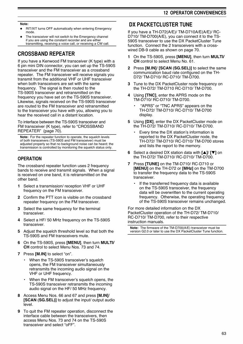
63
12 OPERATOR CONVENIENCES
Note:◆ RIT/XIT turns OFF automatically when entering Emergency
mode.◆ The transceiver will not switch to the Emergency channel
if you are using the constant recorder and are either transmitting, receiving a voice call, or receiving a CW call.
CROSSBAND REPEATER If you have a Kenwood FM transceiver (K type) with a 6 pin mini DIN connector, you can set up the TS-590S transceiver and the FM transceiver as a crossband repeater. The FM transceiver will receive signals you transmit from the additional VHF or UHF transceiver when both transceivers are set with the same frequency. The signal is then routed to the TS-590S transceiver and retransmitted on the frequency you have set on the TS-590S transceiver. Likewise, signals received on the TS-590S transceiver are routed to the FM transceiver and retransmitted to the transceiver you have with you, allowing you to hear the received call in a distant location.
To interface between the TS-590S transceiver and FM transceiver (K type), refer to “CROSSBAND REPEATER” {page 70}.
Note: For the repeater function to operate, the squelch levels of both transceivers (TS-590S and FM transceiver) must be adjusted properly so that no background noise can be heard; the transmission is controlled by monitoring the squelch status only.
OPERATIONThe crossband repeater function uses 2 frequency bands to receive and transmit signals. When a signal is received on one band, it is retransmitted on the other band.
1 Select a transmission/ reception VHF or UHF frequency on the FM transceiver.
2 Confirm the PTT icon is visible on the crossband repeater frequency on the FM transceiver.
3 Select the same frequency for the terminal transceiver.
4 Select a HF/ 50 MHz frequency on the TS-590S transceiver.
5 Adjust the squelch threshold level so that both theTS-590S and FM transceivers mute.
6 On the TS-590S, press [MENU], then turn MULTI/CH control to select Menu Nos. 73 and 74.
7 Press [M.IN] to select “on”.
• When the TS-590S transceiver’s squelch opens, the FM transceiver simultaneously retransmits the incoming audio signal on the VHF or UHF frequency.
• When the FM transceiver’s squelch opens, the TS-590S transceiver retransmits the incoming audio signal on the HF/ 50 MHz frequency.
8 Access Menu Nos. 66 and 67 and press [M.IN]/ [SCAN (SG.SEL)] to adjust the input/ output audio level.
9 To quit the FM repeater operation, disconnect the interface cable between the transceivers, then access Menu Nos. 73 and 74 on the TS-590S transceiver and select “oFF”.
DX PACKETCLUSTER TUNEIf you have a TH-D72(A/E)/ TM-D710A/E(A/E)/ RC-D710/ TM-D700(A/E), you can connect it to the TS-590S transceiver to use the DX PacketCluster Tune function. Connect the 2 transceivers with a cross-wired DB-9 cable as shown on page 70.
1 On the TS-590S, press [MENU], then turn MULTI/CH control to select Menu No. 61.
2 Press [M.IN]/ [SCAN (SG.SEL)] to select the same communication baud rate configured on the TH-D72/ TM-D710/ RC-D710/ TM-D700.
3 Tune to the DX PacketCluster node frequency on the TH-D72/ TM-D710 RC-D710/ TM-D700.
4 Using [TNC], enter the APRS mode on the TM-D710/ RC-D710/ TM-D700.
• “APRS” or “TNC APRS” appears on the TH-D72/ TM-D710/ RC-D710/ TM-D700 display.
5 Using [DX], enter the DX PacketCluster mode on the TH-D72/ TM-D710/ RC-D710/ TM-D700.
• Every time the DX station’s information is reported to the DX PacketCluster node, the TH-D72/ TM-D710/ RC-D710/ TM-D700 stores and lists the report to the memory.
6 Select a desired DX station data with [▲]/ [▼] on the TH-D72/ TM-D710/ RC-D710/ TM-D700.
7 Press [TUNE] on the TM-D710/ RC-D710 or [MENU] on the TH-D72 or [MHz] on the TM-D700 to transfer the frequency data to the TS-590S transceiver.
• If the transferred frequency data is available on the TS-590S transceiver, the frequency data will be overwritten to the current operating frequency. Otherwise, the operating frequency of the TS-590S transceiver remains unchanged.
For more detailed information on the DX PacketCluster operation of the TH-D72/ TM-D710/ RC-D710/ TM-D700, refer to their respective instruction manuals.
Note: The firmware of the TM-D700(A/E) transceiver must be version G2.0 or later to use the DX PacketCluster Tune function.
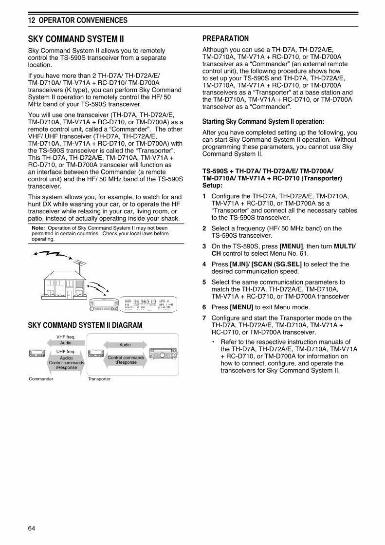
64
12 OPERATOR CONVENIENCES
SKY COMMAND SYSTEM IISky Command System II allows you to remotely control the TS-590S transceiver from a separate location.
If you have more than 2 TH-D7A/ TH-D72A/E/ TM-D710A/ TM-V71A + RC-D710/ TM-D700A transceivers (K type), you can perform Sky Command System II operation to remotely control the HF/ 50 MHz band of your TS-590S transceiver.
You will use one transceiver (TH-D7A, TH-D72A/E, TM-D710A, TM-V71A + RC-D710, or TM-D700A) as a remote control unit, called a “Commander”. The other VHF/ UHF transceiver (TH-D7A, TH-D72A/E, TM-D710A, TM-V71A + RC-D710, or TM-D700A) with the TS-590S transceiver is called the “Transporter”. This TH-D7A, TH-D72A/E, TM-D710A, TM-V71A + RC-D710, or TM-D700A transceier will function as an interface between the Commander (a remote control unit) and the HF/ 50 MHz band of the TS-590S transceiver.
This system allows you, for example, to watch for and hunt DX while washing your car, or to operate the HF transceiver while relaxing in your car, living room, or patio, instead of actually operating inside your shack.
Note: Operation of Sky Command System II may not been permitted in certain countries. Check your local laws before operating.
SKY COMMAND SYSTEM II DIAGRAMVHF freq.
Commander Transporter
Audio Audio
UHF freq.
AudiosControl commands
tResponse
Control commandstResponse
PREPARATIONAlthough you can use a TH-D7A, TH-D72A/E, TM-D710A, TM-V71A + RC-D710, or TM-D700A transceiver as a “Commander” (an external remote control unit), the following procedure shows how to set up your TS-590S and TH-D7A, TH-D72A/E, TM-D710A, TM-V71A + RC-D710, or TM-D700A transceivers as a “Transporter” at a base station and the TM-D710A, TM-V71A + RC-D710, or TM-D700A transceiver as a “Commander”.
Starting Sky Command System II operation:
After you have completed setting up the following, you can start Sky Command System II operation. Without programming these parameters, you cannot use Sky Command System II.
TS-590S + TH-D7A/ TH-D72A/E/ TM-D700A/ TM-D710A/ TM-V71A + RC-D710 (Transporter) Setup:
1 Configure the TH-D7A, TH-D72A/E, TM-D710A, TM-V71A + RC-D710, or TM-D700A as a “Transporter” and connect all the necessary cables to the TS-590S transceiver.
2 Select a frequency (HF/ 50 MHz band) on the TS-590S transceiver.
3 On the TS-590S, press [MENU], then turn MULTI/CH control to select Menu No. 61.
4 Press [M.IN]/ [SCAN (SG.SEL] to select the the desired communication speed.
5 Select the same communication parameters to match the TH-D7A, TH-D72A/E, TM-D710A, TM-V71A + RC-D710, or TM-D700A transceiver
6 Press [MENU] to exit Menu mode.
7 Configure and start the Transporter mode on the TH-D7A, TH-D72A/E, TM-D710A, TM-V71A + RC-D710, or TM-D700A transceiver.
• Refer to the respective instruction manuals of the TH-D7A, TH-D72A/E, TM-D710A, TM-V71A + RC-D710, or TM-D700A for information on how to connect, configure, and operate the transceivers for Sky Command System II.

65
CONNECTING PERIPHERAL EQUIPMENT
TERMINAL DESCRIPTIONSCOM CONNECTOR
Pin No. Pin Name Function I/O
1 NC No connection —
2 RXD Transmit data O
3 TXD Receive data I
4 NC No connection —
5 GND Ground —
6 NC No connection —
7 RTS Receive enable I
8 CTS Transmit enable O
9 NC No connection —
ACC2 CONNECTOR
Pin No. Pin Name Function I/O
1 NC No connection —
2 RTTY RTTY key input I
3 ANO
Audio output from the transceiver• Connect to the audio input of the TNC, MCP, or PC (or PC
interface connection).• Audio output level is independent from the AF control setting.• Audio output level can be changed by adjusting the value
in Menu No. 67. Set the value to a moderate audio output level. The default value of 4 is approximately 0.5 Vp-p, which is a standard modulating signal. The settings of 0 ~ 9 vary from approximately 0 Vp-p to 1.2 Vp-p.
• Impedance: Approx. 10 kΩ.
O
4 GND Ground —
5 PSQ
Transceiver squelch control• Connect to the squelch input of the TNC, MCP, or PC
connection interface.• Squelch open: Low impedance• Squelch closed: High impedance
O
6 NC No connection —
7 NC No connection —
8 GND Ground —
9 PKS
PTT input for data communication• Connect to the PTT output of the TNC, MCP, or PC
connection interface.• Microphone audio input mutes when transmitting.
I
10 NC No connection —
11 ANI
Audio input for data communication• Connect to the audio output of the TNC, MCP, or PC (or PC
interface connection).• Audio input level is independent from the microphone gain
(set with the [MIC] key).• Audio input level can be changed by adjusting the value in Menu
No. 66. The default value of 4 is approximately 10 mVrms, which is a standard modulating signal. The settings of 0 ~ 9 vary from approximately no modulation to approximately 1 mVrms.
• Impedance: Approx. 10 kΩ.
I
12 GND Ground —
13 SSPTT input (same as the front panel MIC connector) • During transmission, the audio input of ACC2 connector
terminal 11 (ANI) and the USB terminal are muted.I

66
13 CONNECTING PERIPHERAL EQUIPMENT
REMOTE CONNECTOR
Pin No. Pin Name Function I/O
1 SPO Speaker output O
2 COM Common terminal I/O
3 SS
Standby; when grounded, the transceiver enters TX mode.• During transmission, the audio input of ACC2 connector
terminal 11 (ANI) and the USB terminal are muted.
I
4 MKE When connected with the common terminal, the amplifier enters TX mode. I/O
5 BRK When connected with the common terminal, the amplifier enters RX mode. I/O
6 ALC ALC input from the amplifier (approx. -7 V). I
7 RL Approx. +12 V DC is output when in TX mode (10 mA max.). O
EXT.AT CONNECTOR (for AT-300)
Pin No. Pin Name Function I/O
1 GND Ground —
2 TT AT-300 control input/ output I/O
3 GND Ground —
4 NC No connection —
5 TS AT-300 control input/ output I/O
6 14S Power supply for EXT.AT Switched 13.8V. O
MIC CONNECTOR
Pin No. Pin Name Function I/O
1 MIC MIC signal input I
2 SS MIC standby (PTT) control I
3 MD MIC Down control I
4 MU MIC UP control I
5 8A Switched 8V O
6 NC No connection —
7 MSG MIC GND —
8 MCG GND —

67
13 CONNECTING PERIPHERAL EQUIPMENT
Note: Use a USB/ RS-232C cable shorter than 3 meters.
COMPUTERThe USB connector allows you to directly connect a computer by using a USB (AB type) or RS-232C cable. By connecting a USB cable to the PC, you can enable the input and output of the transmission and reception of sound. You must use the ARUA-10 software, available at the following URL, to control the USB audio system line of the PC. (The virtual COM port driver can also be downloaded from the following URL.)
http://www.kenwood.com/i/products/info/amateur/software_download.html
TS-590S
(f)
(f)
To USB port
USB cable
To RS-232C serial port
RS-232C straight cable
Personal computer
• To transmit the signal from the PC, you must either turn the DATA VOX function ON or ground pin 9 (PKS) of the ACC2 connector to pin 8 (GND). (Refer to page 30 for the DATA VOX function.)
Note:◆ The USB cable and RS-232C cable are not included; purchase them separately.◆ Connect the USB cable directly to the PC.◆ In theory, a delay occurs in the USB audio system. Therefore, sound may be clipped when using a PC in this system. Use this USB
audio system in cases where you are recording communications that do not require quick responses to a PC.
COMPATIBLE TRANSCEIVERWhen transferring data to or from another TS-590S, TS-480HX/SAT, TS-2000/X, TS-570S/D, or TS-870S, directly connect the 2 transceivers using the COM connectors.
(f) (f)
TS-590S
RS-232C cross cable
Compatible transceiver
DB-9 connector wiring (Cross-wired)

68
13 CONNECTING PERIPHERAL EQUIPMENT
RTTY OPERATIONUse the ACC 2 connector to interface with your MCP. If your MCP supports RTTY keying output, connect the output to pin 2 of the ACC 2 connector. Connect the demodulation input line of the MCP to pin 3 of the ACC 2 connector. Also, connect the transmission control line of the MCP to pin 13 of the ACC 2 terminal. Select “FSK” or “FSR” when you operate the RTTY mode.
Note: Do not share a single power supply between the transceiver and the RTTY equipment. Keep as wide a separation as possible between the transceiver and the RTTY equipment to reduce noise-pickup by the transceiver.
TS-590S
MCP
Power supply for MCP
Personal computer
HF/ 50 MHz LINEAR AMPLIFIERConnect an external transmission power amplifier to the REMOTE connector. Switch ON the linear amplifier control relay via Menu No. 53 (HF) or 54 (50 MHz). Select “2” or “3” if you use the internal relay to control the linear amplifier status.
The TX/ RX relay response time is 10 [ms] when you have selected CW Full Break-in and 25 [ms] when you have selected CW Semi Break-in.
Note: The TX/ RX control method differs, depending on external amplifier models. Some amplifiers enter the TX mode when the control terminal is grounded. For those amplifiers, connect pin 2 of the REMOTE connector to the GND terminal of the amplifier and connect pin 4 of the connector to the control terminal of the amplifier.
(The TL-922 Linear Amplifier is a discontinued model. It may no longer be available in your area.)
TS-590S
TL-922 (HF linear amplifier)
24
1
6 7
3
5
RT
Control relay
GND
REMOTE connector (front view)

69
13 CONNECTING PERIPHERAL EQUIPMENT
ANTENNA TUNERUse the ANT 1 and AT connectors to connect an AT-300 external antenna tuner. If you connect the external antenna tuner to the ANT 2 connector, it will not function.
Note: The AT-300 cannot be used for 50 MHz operation.
TS-590SAT-300
ANT 1 connector
(The AT-300 Antenna Tuner is a discontinued model. It may no longer be available in your area.)
TNC AND MCPUse the DATA connector to connect the Audio input/ output lines from a Terminal Node Controller (TNC) for Packet operation, a Multimode Communications Processor (MCP) for operation on AFSK, Packet, PacTOR, AMTOR, G-TORTM, PSK31, or FAX, or a Clover interface. Also use the ACC 2 connector to connect SSTV and phone patch equipment.
• Connect the TNC or MCP to the ACC 2 connector using a cable equipped with a 13-pin DIN plug.
• Connecting the TNC or MCP to a personal computer or dumb terminal requires an RS-232C cable.
• Select LSB or USB mode (it depends on the communication mode) when you operate the MCP/ TNC.Note: Do not share a single power supply between the transceiver and the TNC or MCP. Keep as wide a separation as possible between the transceiver and the computer to reduce noise-pickup by the transceiver.
TS-590S
TNC/MCP
Power supply for TNC/ MCP
Personal computer

70
13 CONNECTING PERIPHERAL EQUIPMENT
DX PACKETCLUSTER TUNEIf you have a TH-D72A/E/ TM-D710A/E/ RC-D710/ TM-D700A/E, you can connect the TH-D72A/E/ TM-D710A/E/ RC-D710/ TM-D700A/E to the TS-590S transceiver to use the DX PacketCluster Tune function. Connect the 2 transceivers with a cross-wired RS-232C cable as shown below. (For connecting to the TH-D72A/E, refer to the TH-D72A/E instruction manual.)
RC-D710 + PG-5J
TM-D700A/E
TS-590STM-D710A/E/RC-D710 + TM-V71A/E
(m)
(f)
(f)
(f)
PG-5G
RS-232C cross cable
CROSSBAND REPEATERIf you have a Kenwood FM transceiver (K type) with a 6 pin mini DIN connector, you can connect the FM transceiver to the TS-590S transceiver to use the Crossband repeater function. Connect the 2 transceivers with a DIN (13-pin)/ mini DIN cable (6-pin) as shown below.
TM-D700A
TS-590S
TM-D710A/ TM-V71A
PR1
SQC
PKSPSQ
PKD
PKSANI
ANO
DIN (13-pin)/ Mini DIN (6-pin)
DIN (13-pin) pulg Mini DIN (6-pin) pulg
After connecting the 2 transceivers with the cable, access Menu Nos. 73 (PKS polarity) and 74 (Busy lockout) on the TS-590S transceiver and select “on”. You will further need to adjust the audio input/ output level of the TS-590S transceiver using Menu Nos. 66 and 67.

71
INSTALLING OPTIONS
You will require a #1 Philips screwdriver to install the VGS-1 or SO-3 TCXO. You will also need a soldering iron (approx. 30 watts) to install the SO-3 TCXO.
Switch OFF the transceiver power and unplug the DC power cable before performing any installations.
REMOVING THE BOTTOM CASEWhen installing the optional VGS-1 or SO-3 TCXO, remove the bottom case of the transceiver:
1 Remove the 10 screws.
2 Lift off the bottom case.
VGS-1 VOICE GUIDE & STORAGE UNIT1 Remove the shield cover (4 screws).
2 There are 5 rubber cushions in the VGS-1 package. Use the 2 rubber cushions shown below (20 x 30 x 2 mm and 21 x 21 x 2.5 mm) and attach them to the VGS-1.
• The remaining cushions are not used.
3 Plug the VGS-1 into the VGS-1 connector of the PC board, pressing down on the top of the VGS-1 until secure.
4 Replace the shield cover and tighten the 4 screws.
5 Replace the bottom case (10 screws).Note: After installation, you can adjust the VGS-1 playback and voice guide volume by selecting Menu Nos. 05 and 06.

14 INSTALLING OPTIONS
72
SO-3 TCXOThe SO-3 option improves the transceiver frequency stability to ±0.5 ppm.
1 Remove the CN503 connector and TCXO PCB screw, as shown below.
TCXO PCB
CN503
TCXO PCB
CN503
2 Remove the TCXO PCB.
3 Insert the SO-3 TCXO.
4 Solder all pins on the reverse side of the PCB.
5 Re-insert the TCXO PCB in the transceiver.
6 Connect the CN503 and tighten the screw.
7 Move the C903 and C904 jumper as shown below.
CN903 CN904TC501
Note:◆ To avoid misplacing the jumper, keep it attached to 1 pin of
C903 or C904.◆ When removing the SO-3 TCXO, replace the jumper to its
original position.
8 Replace the bottom case (10 screws).
REFERENCE FREQUENCY CALIBRATION Note: The transceiver is adjusted at the factory prior to shipping. Do not perform this adjustment unless it is necessary.
1 Set the following on the transceiver:
• Mode: CW
• AF control: Center
• Menu No. 34 (CW RX pitch): 800 Hz
• SHIFT control: 800 Hz
• RIT function: OFF
• Break-in function (VOX): OFF
2 Remove the bottom case (10 screws) from the transceiver.
3 Tune in a standard frequency station such as WWV or WWVH at, for example, 10.000.00 MHz or 15.000.00 MHz.
• Adjust the Tuning control so that the display reads the exact frequency of the station.
• You should hear a beat tone of approximately 800 Hz.
• For 800 Hz:faf = (fdisplay/15.600 x Δfreference) + 800 Hz where Δfreference is the shift from the 15.6 MHz reference frequency.
4 Close your CW key. You will hear a transmit sidetone of approximately 800 Hz.
• This sidetone produces a double beat tone when it combines with the received signal.
• Adjust the AF control to hear the double beat clearly.
• For 800 Hz:fsidetone = 800 Hz ±50 ppm (= 800 ±0.04 Hz) where Δfreference is the shift from the 15.6 MHz reference frequency.
5 TS-590S transceiver without SO-3:
Adjust the trimmer (TC501) to minimize the frequency difference between the received 800 Hz tone and the 800 Hz sidetone.
TS-590S transceiver with SO-3:
Adjust the trimmer inside the SO-3 using the supplied plastic adjustment tool. Minimize the frequency difference between the received 800 Hz tone and the 800 Hz sidetone.

73
14 INSTALLING OPTIONS
MB-430 MOBILE BRACKETATTENTION: When installing the MB-430, use the SEMS Screws provided with the TS-590S.
When installing the MB-430, attach the supplied plastic spacers to the transceiver in advance. This is necessary to protect the TS-590S transceiver from scratches.
Make sure the tab faces out
Plastic spacers
Once the bracket is installed onto the vehicle, prepare the transceiver by loosely screwing in the rear screws. Hook those screws onto the rear guide rail of the mounting bracket then adjust the transceiver to your desired angle before tightening the screws. Insert and tighten the front screws to secure the transceiver in place.
Rear screw
Front screw
To remove the transceiver from the bracket, first remove the front screws, then loosen the rear screws slightly and pull the transceiver forward to unlatch it from the bracket.
Do not install the transceiver so that it is vertically on its side.
PRECAUTIONS• When operating mobile, do not attempt to
configure the transceiver while driving; it is too dangerous.
• Use of the transceiver while you are driving may be against traffic laws. Please check and observe the vehicle regulations in your area.
74
TROUBLESHOOTING
SERVICE NOTEIf you desire to correspond on a technical or operational problem, please make your note short, complete, and to the point. Help us help you by providing the following:
• Model and serial number of equipment
• Question or problem you are having
• Other equipment in your station pertaining to the problem
• Meter readings
• Other related information (Menu setup, mode, frequency, key sequence to induce malfunction, etc.)
Do not pack the equipment in crushed newspapers for shipment. Extensive damage may result during rough handling or shipping.
Note:◆ Record the date of purchase, serial number, and dealer from
whom the transceiver was purchased.◆ For your own information, retain a written record of any
maintenance performed on the transceiver.◆ When claiming warranty service, please include a photocopy
of the bill of sale or other proof-of-purchase showing the date of sale.
CLEANINGThe keys, controls, and case of the transceiver are likely to become soiled after extended use. Remove the controls from the transceiver and clean them with a neutral detergent and warm water. To clean the case, use a neutral detergent (no strong chemicals) and a damp cloth.
GENERAL INFORMATIONYour transceiver has been factory aligned and tested to specification before shipment. Under normal circumstances, the transceiver will operate in accordance with these operating instructions. All adjustable trimmers, coils, and resistors in the transceiver are preset at the factory. They should only be readjusted by a qualified technician who is familiar with this transceiver and has the necessary test equipment. Attempting service or alignment without factory authorization may void the transceiver warranty.
When operated properly, the transceiver will provide years of service and enjoyment without requiring further realignment. The information in this section gives some general service procedures requiring little or no test equipment.
SERVICEIf it is ever necessary to return the equipment to your dealer or service center for repairs, pack the transceiver in its original box and packing material. Include a full description of the problems experienced. Include both your telephone number and fax number (if available) along with your name and address in case the service technician needs to call for further information while investigating your problem. Don’t return accessory items unless you feel they are directly related to the service problem. Please do not send subassemblies or printed circuit boards. Send the complete transceiver.
You may return your transceiver for service to the authorized Kenwood dealer from whom you purchased it or any authorized Kenwood service center. A copy of the service report will be returned with the transceiver.
Tag all returned items with your name and call sign for identification. Please mention the model and serial number of the transceiver in any communication regarding the problem.

75
15 TROUBLESHOOTING
TROUBLESHOOTINGThe problems described in this table are commonly encountered operational malfunctions. These types of difficulties are usually caused by improper hook-up, accidental incorrect control settings, or operator error due to incomplete programming. These problems are usually not caused by circuit failure. Please review this table and the appropriate section(s) of this instruction manual before assuming your transceiver is defective.
Note: Placing a powered portable transceiver near this transceiver may cause noise in the transceiver.
Problem Probable Cause Corrective Action Page
The transceiver will not power up after connecting a 13.8 V DC power supply and pressing [ ]. Nothing appears on the display and no receiver noise is heard.
1 DC power supply is OFF.2 Faulty power cable.
3 The power cable is not connected securely.
4 The power cable fuse is open.
1 Switch the DC power supply ON.2 Inspect the power cable. Confirm that the
polarities are correct (Red: positive (+); Black; negative (–)).
3 Confirm the connections to the DC power supply are secure.
4 Look for the cause of the blown fuse. After inspecting and correcting any problems, install a new fuse of the specified rating.
101
1
2
After switching the power ON, the transceiver does not function normally. For example, no digits or incorrect digits appear on the display.
1 The input voltage is outside 13.8 V DC ±15% (11.7 ~ 15.8 V DC)
2 The microprocessor has malfunctioned.
1 Correct the input voltage or use a 12 ~ 16 V battery.
2 Review “MICROPROCESSOR RESET”. After understanding what data will be lost, do a VFO Reset. If the problem remains, do a Full Reset.
1
78
After switching the transceiver ON, the transceiver refuses to transmit.
The current rating of the DC power supply is too low.
Use a DC power supply that has a 20.5 A or higher current rating
1
The transceiver does not respond correctly after pressing key combinations or turning controls per instructions in this manual.
1 Procedures are not being followed precisely.
2 The Frequency Lock function is ON.
3 The microprocessor and its memory need to be reset.
1 Review “WRITING CONVENTIONS FOLLOWED”.
2 Press and hold [FINE (F.LOCK)] to switch the function OFF. The “ ” icon disappears.
3 Review “MICROPROCESSOR RESET”. After understanding what data will be lost, do a Partial Reset. If the problem remains, do a Full Reset.
ii
53
78
The frequency cannot be changed.
The Frequency Lock function is ON.
Press and hold [FINE (F.LOCK)] to switch the function OFF. The “ ” icon disappears.
53
SSB audio quality is very poor; the high or low audio frequencies are absent.
1 The wrong operation mode is selected for the receiver.
2 The IF filter is incorrectly set.
3 Noise Reduction 1 or 2 is ON.
4 Beat Cancel 1 or 2 is ON.
1 Select USB or LSB for the mode.
2 Turn the HI/SHIFT or LO/WIDTH control to adjust the DSP filter width.
3 Press [NR (LEV)] until the NR function turns OFF.
4 Press [BC (A.NOTCH)] until the BC function turns OFF.
11
38
39
39
No signals are received or receive sensitivity seems poor.
1 The SQL control is fully clockwise.
2 The Attenuator is ON.3 MIC [PTT] is pressed.
4 The IF filter bandwidth was incorrectly set.
5 The wrong antenna connector (ANT 1 or ANT 2) was selected.
6 The pre-amplifier is OFF.
7 An internal DSP error occurs.
1 Turn the SQL control counterclockwise.
2 Press [ATT (RX ANT)] to switch the Attenuator is OFF.
3 Release MIC [PTT].4 Review “DSP FILTERS”, and set the
controls accordingly.5 Press and hold [PRE (ANT 1/2)] to select the
other antenna connector.
6 Press [PRE (ANT 1/2)] to switch the function ON.
7 Restart the transceiver by turning the power OFF and then back ON. If the problem persists, consult Kenwood authorized Service Center.
12
40
1338
50
40
—

76
15 TROUBLESHOOTING
Problem Probable Cause Corrective Action Page
No signals are received or receive sensitivity seems poor; S-meter is reading full scale.
The RF gain was set too low. Turn the RF control clockwise to increase the RF gain.
10
Received signals are completely unintelligible
The wrong modulation was selected.
Select the correct modulation mode. 11
Memory Scan will not start scanning.
1 The SQL control was not set correctly.
2 Less than 2 memory channels were unlocked.
3 Less than 2 memory channels were programmed.
1 Adjust the SQL control to just eliminate background noise.
2 Unlock at least 2 memory channels.
3 Store data in at least 2 memory channels.
12
44
41
Memory Scan will not scan one of the stored channels; the desired channel is not locked out.
With Group Scan selected, the channel you want to scan is in a different group.
Select the Memory Group that contains the memory channel you want to scan.
49
Program Scan will not start scanning.
The start and end frequencies are identical
Store different start and end frequencies. 46
AT does not finish successfully.
The impedance of the coaxial cable and antenna was not matched. Tuning does not successfully finish depending on conditions, although the SWR meter indicates smaller than 3:1.
Adjust the antenna system to lower the SWR. 50
The internal tuner is bypassed immediately after tuning is started.
The SWR of the antenna system is too high.
Adjust the antenna system to lower the SWR 50
You cannot transmit even though you press MIC [PTT], or transmissinos result in no contacts.
1 The microphone plug was not inserted completely into the MIC connector.
2 The Transmit Inhibit function is ON.
3 CW or FSK was selected instead of a voice mode.
4 The DSP TX filter bandwidth was improperly selected.
5 The wrong antenna connector (ANT 1 or ANT 2) was selected.
1 Turn OFF the power, ensure the MIC connector has no foreign objects in it, then plug in the connector firmly.
2 Change Menu No. 60 to OFF.
3 Select the correct voice mode.
4 Adjust the settings in Menu Nos. 25, 26.
5 Press and hold [PRE (ANT 1/2)] to select the other antenna connector.
2
32
11
31
50
Attempting to transmit results in the “HELLO” message appearing and the reception mode being restored.
1 The antenna is not connected correctly.
2 The impedances of the antenna and transceiver are not properly matched.
3 The input voltage is outside 13.8 V DC ± 15% (11.7 ~ 15.8 V DC).
4 The current rating of the DC power supply is not enough.
1 Check the antenna connection. Correct as necessary.
2 Reduce the SWR of the antenna system.
3 Correct the input voltage or use a 12 ~ 16 V battery.
4 Use a DC power supply that has a current rating of more than 20.5 A at 13.8 V DC.
1
50
1
1
The transceiver has low transmission power.
1 The microphone gain is set too low.
2 Poor antenna system connections are causing high SWR.
1 When in SSB or AM mode, increase the microphone gain.
2 Check the antenna connections. Confirm that the antenna tuner is reporting a low SWR.
13
50

77
15 TROUBLESHOOTING
Problem Probable Cause Corrective Action Page
VOX does not operate.
The VOX gain is set too low. Increase the VOX gain. 30
HF/ 50 MHz Linear amplifier does not operate.
1 The linear amplifier control is OFF.
2 The REMOTE connector wiring is wrong or faulty.
1 Set Menu No. 53 (HF) or 54 (50 MHz) to 1, 2, or 3.
2 Inspect the REMOTE connector wiring and correct it as necessary.
53
66
The transceiver’s output power decreases after a short operating time.
1 The air filters for the cooling fans have been congested with dust.
2 The cooling fans cannot provide enough air flow to cool the transceiver down.
1 Contact a Kenwood authorized service center to clean the filters.
2 Relocate the transceiver so that air can easily flow through the TS-590S to keep the unit cooled.
—
—
You cannot access and use repeaters.
1 Many repeaters require a subtone or 1750 Hz tone to access.
2 Transmission and/or reception frequency is wrong.
1 Review “FM REPEATER OPERATION” and select the correct frequency and type of subtone.
2 You must transmit on the repeater’s input frequency and receive on the repeater’s output frequency. Refer to “FM REPEATER OPERATION”.
25
25
Digital operation results in few or no connects or contacts with other stations.
1 Physical connections between the transceiver, computer, and TNC/ MCP are incorrect, or software settings in the TNC/ MCP are wrong.
2 Different transmission and reception frequencies are being used.
3 The levels between the transceiver and the TNC/ MCP are incorrect.
4 Your transmitted signal or the incoming receive signal is too weak.
5 The TX delay time parameter in your TNC/ MCP was incorrectly set.
1 Re-check all connections using this manual, your TNC/ MCP manual, and your computer hardware manual as references.
2 Confirm that the RIT and XIT functions are switched OFF. Confirm that you are not operating split frequency.
3 Adjust TX and RX levels using Menu Nos. 66 and 67, and level controls on your TNC/ MCP.
4 Reorient/ relocate your antenna or increase your antenna gain.
5 Set the TNC/ MCP TX delay time to more than 300 ms.
67,69
29,31
58,69
1
—
Attempts at controlling the transceiver with the computer have failed.
1 Problem with cable that connects the PC to the TS-590S.
2 Communication parameters set in your terminal program do not match the transceiver parameters.
1 Check the cable and cable connections.
2 Use the same parameters in the terminal and the transceiver. Check Menu Nos. 61 and 62.
67
57
“TEMP-HI” appears and “CHECK” in Morse code sounds.
A sensor in the transceiver detected high temperature.
Stop transmitting and let the transceiver cool down for a while. Contact a Kenwood authorized service center to clean the internal air filters.
—
Transmission suddenly stops.
The voltage of the DC power supply is too high.
Adjust the DC power supply voltage to 13.8 V DC.
1
“DSP ERR x” appears (where x is a number from 0 ~ 3).
An internal DSP error occurs. Restart the transceiver by turning the power OFF and then back ON. If the problem persists, consult Kenwood authorized Service Center.
—
“VGS ERR” appears. An internal error occurred in the VGS-1.
Confirm that the connector of the VGS-1 is securely connected to the transceiver, then turn the transceiver power OFF and ON. If the problem persists, contact a Kenwood authorized service center for repairs.
71

78
15 TROUBLESHOOTING
Problem Probable Cause Corrective Action Page
A message cannot be recorded/ played back or no announcement can be heard.
There is a communication error between the transceiver and the VGS-1.
Confirm that the connector of the VGS-1 is securely connected to the transceiver. Perform the Full reset. If the problem persists, contact a Kenwood authorized service center for repairs (with the VGS-1 attached).
71,78
The transceiver output power seems to be low in SSB mode.
Most of the external RF power meters measure the average RF power. So, the meter reading is low when you operate and talk in SSB mode. The LCD meter used in the TS-590S has relatively fast response time but it is not fast enough to measure the accurate PEP (Peak Envelope Power).
Apply a continuous single tone (1 kHz) to the microphone audio input to measure the RF output power. The PEP will be the same as this RF output level.
—
The PC and external equipment is not modulating.
The input terminal is different from the one specified (Menu No. 63) for the external equipment.
Confirm that the setting of Menu No. 63 matches the input terminal for the external equipment.
58
MICROPROCESSOR RESETIf your transceiver seems to be malfunctioning, resetting the microprocessor to its default settings may resolve the problem. There are 2 levels of resetting the microprocessor of the TS-590S transceiver: Partial Reset and Full Reset.
INITIAL SETTINGSFor each VFO, the factory defaults for the operating frequency and mode are as follows:
• VFO A: 14.000.00 MHz/ USB
• VFO B: 14.000.00 MHz/ USB
The Memory channels and Quick Memory channels have no data stored.
VFO RESETPerform a VFO Reset if a key or control does not function according to the instructions in this manual. The following data is NOT erased by performing a VFO Reset.
• Memory channel data
• Menu settings
• Antenna tuner preset data
• ANT 1/ ANT 2 selection data
• Frequency and mode data for the Auto Mode function
• Various adjustment setting values
1 Turn the transceiver power OFF.
2 Press [A/B (A=B)] + [ ] to switch the transceiver ON.
• A confirmation message appears on the display.
3 Turn the MULTI/CH control and select “VFO RESET”.
4 Press [A/B (A=B)] to perform the VFO reset.
• A confirmation message appears when performing the VFO Reset. Press [A/B (A=B)] again to proceed. Otherwise, press any other key to cancel the VFO Reset and return to normal operation.
• The VFOs reset to the factory default values.
FULL RESETPerform a Full Reset if you want to erase all the data in all the memory channels. In addition, this function resets all the settings that you customized, to the factory defaults (i.e.- menu settings, antenna tuner preset data, etc.).
1 Turn the transceiver power OFF.
2 Press [A/B (A=B)] + [ ] to switch the transceiver ON.
• A confirmation message appears on the display.
3 Turn the MULTI/CH control and select “FULL RESET”.
4 Press [A/B (A=B)] to perform the Full reset.
• A confirmation message appears when performing the Full Reset. Press [A/B (A=B)] again to proceed. Otherwise, press any other key to cancel the Partial Reset and return to normal operation.
• All frequencies, modes, memory data, adjustment values, and AT preset data are set to the factory default values.

79
15 TROUBLESHOOTING
OPERATION NOTICESThe transceiver has been designed and engineered to avoid possible hardware glitches. However, you may notice the following symptoms when you operate the transceiver. These symptoms are not malfunctions.
DC POWER SUPPLYAs stated in the SPECIFICATIONS {page 80}, this transceiver requires a supplied DC voltage source of 13.8 V ±15%. If you find that the transceiver cannot be switched ON, or that it shuts OFF automatically, the DC voltage may be outside the specified range.
In such a case, remove the DC cable from the transceiver immediately and confirm that the supplied voltage is within the specified range.
INTERNAL COOLING FANThe transceiver detects the temperature of the final department regardless of the transmission and reception state of the main body, in order to protect the internal circuits from high temperatures. The cooling fan speed and transmission output is controled through the following.
• When the thermistor detects a rise in temperature in the final department, the cooling fan turns on at low speed. As the temperature rises, the speed of the cooling fan increases.
• When an abnormally high temperature is detected, the temperature protection circuit activates, reducing the transmission output to the lowest possible power.
When the temperature protection circuit activates, return the transceiver to receive mode and leave the transceiver power ON. Allow time for the cooling fan to return the internal temperature to normal.
• If you turn the transceiver power OFF, the cooling fan will not run and it will take much longer for the internal temperature to decrease.
INTERNAL BEATSOn some spots of the receiver frequencies, the S-meter moves or you cannot receive any signals. This is inevitable when you use superheterodyne receivers. You may notice the signals on the following spots of the frequency:
• 15.600.00 MHz
• 31.200.00 MHz
• 46.800.00 MHz
AGCWhen you turn the AGC function OFF {page 29}, the receiving audio signals can be distorted. In this case, decrease the RF gain, turn the pre-amplifier OFF, or turn the attenuator ON. In general, the RF gain must be greatly reduced when the AGC is turned OFF.
60m BAND OPERATION (K-TYPE/ USA ONLY)Effective from July 3, 2003, FCC Report and Order (R&O) in ET Docket 02-98 granted US amateurs secondary access to five discrete channels in the vicinity of 5 MHz. General, Advanced, and Amateur Extra licensees may use the following five channels on a secondary basis with a maximum effective radiated power of 50 W PEP relative to a half wave dipole. Only upper sideband suppressed carrier voice transmissions may be used. The frequencies are 5330.5, 5346.5, 5366.5, 5371.5 and 5403.5 kHz. The occupied bandwidth is limited to 2.8 kHz centered on 5332, 5348, 5368, 5373, and 5405 kHz respectively. The TS-590S transceiver stops at the 60 m band as you scroll up or down the amateur radio frequency bands. For more information, contact ARRL or search their Web site using the key word “60 meter”:
http://www.arrl.org

OPTIONAL ACCESSORIES
80
PS-60
Regulated DC Power Supply (22.5 A)
HS-6
Small Headphones
SP-50B
Mobile Speaker
MC-47
Multi-function Microphone
ARCP-590/ ARHP-590
Remote control software
PG-20
DC cable (7 m/ 23 ft)
SO-3
TCXO unit
MC-60A
Desk-top Microphone
SP-23
External Speaker
VGS-1
Voice Guide and Storage unit
HS-5
Delux Headphones
MC-43S
Microphone
MC-90
DSP-compatible Desk-top Microphone
MB-430
Mobile Bracket
Download the free ARCP-590/ARHP-590 software from the following URL:
http://www.kenwood.com/i/products/info/amateur/software_download.html
Microphone sensitivity is low in FM mode.

81
SPECIFICATIONS
GeneralMode J3E (LSB, USB)/ A1A (CW)/ A3E (AM)/ F3E (FM)/ F1B (FSK)
Number of memory channels 110 + 10 (Quick memory channels)
Antenna impedance 160 m ~ 6 m band 50 Ω (with built-in antenna tuner 16.7 ~ 150 Ω)
Supply Voltage DC 13.8 V±15%
Grounding method Negative ground
CurrentTransmit (max.) Less than 20.5 A
Receive (no signal) Less than 1.5 A
Usable temperature range –10°C ~ +50°C (+14°F ~ +122°F)
Frequency stability without SO-3 –10°C ~ 50°C Within ±5 ppm
Frequency stabilitywith SO-3 –10°C ~ 50°C Within ±0.5 ppm
Dimensions (W x H x D Projections not included) 270 x 96 x 291 mm/ 10.63 x 3.78 x 11.46 in
Weight Approx. 7.4 kg/ 16.3 lb
Transmitter
Frequency range
160 m band 1.8 ~ 2.0 MHz (K type)/ 1.81 ~ 2.0 MHz (E type)
80 m band 3.5 ~ 4.0 MHz (K type)/ 3.5 ~ 3.8 MHz (E type)
60 m band 5.1675 MHz (K type)5.25 ~ 5.45 MHz (K type)
40 m band 7.0 ~ 7.3 MHz (K type)/ 7.0 ~ 7.2 MHz (E type)
30 m band 10.1 ~ 10.15 MHz
20 m band 14.0 ~ 14.35 MHz
17 m band 18.068 ~ 18.168 MHz
15 m band 21.0 ~ 21.45 MHz
12 m band 24.89 ~ 24.99 MHz
10 m band 28.0 ~ 29.7 MHz
6 m band 50.0 ~ 54.0 MHz (K-type) / 50.0 ~ 52.0 MHz (E type)
Output power
SSB/ CW/ FSK/ FM
Max. 100 W
Min. 5 W
AMMax. 25 W
Min. 5 W
Maximum frequencydeviation (FM)
Wide Less than ±5 kHz
Narrow Less than ±2.5 kHz
Modulation
SSB Balanced
AM Low power
FM Reactance
Spurious emissions160 m ~ 10 m band Less than –50 dB
6 m band Less than –60 dB
Carrier suppression (SSB) More than 50 dB
Unwanted sideband suppression(modulation frequency 1.0 kHz) More than 50 dB
Transmit frequency response –6 dB: 400 - 2600 Hz

82
17 SPECIFICATIONS
TransmitterXIT shift frequency range ±9.999 kHz
Microphone impedance 600 Ω
Receiver
Circuit type
RX1 (1.8/ 3.5/ 7/ 14/ 21 MHz band/ IF band width of 2.7 kHz or less (SSB/CW/FSK))
RX2 (Other)
Double conversion superheterodyne
Triple conversion superheterodyne
Frequency range 0.03 ~ 59.999999 MHz
Intermediate frequency
1st IF 11.374 MHz 73.095 MHz
2nd IF 24 kHz 10.695 MHz
3rd IF − 24 kHz (except FM)/ 455 kHz (FM)
Sensitivity
SSB/ CW/ FSK (S/N 10 dB)
0.13 ~ 0.522 MHz: Less than 0.5 μV0.522 ~ 1.705 MHz: Less than 4 μV1.705 ~ 24.5 MHz: Less than 0.2 μV24.5 ~ 30.0 MHz: Less than 0.13 μV50.0 ~ 54.0 MHz: Less than 0.13 μV
AM (S/N 10 dB)
0.13 ~ 0.522 MHz: Less than 6.3 μV0.522 ~ 1.705 MHz: Less than 31.6 μV1.705 ~ 24.5 MHz: Less than 2 μV24.5 ~ 30.0 MHz: Less than 1.3 μV50.0 ~ 54.0 MHz: Less than 1.3 μV
FM (12 dB SINAD) 28.0 ~ 30.0 MHz: Less than 0.22 μV50.0 ~ 54.0 MHz: Less than 0.22 μV
Squelch sensitivitySSB/ CW/ FSK/ AM
0.13 ~ 0.522 MHz: Less than 5.6 μV0.522 ~ 1.705 MHz: Less than 18.0 μV1.705 ~ 30.0 MHz: Less than 1.8 μV50.0 ~ 54.0 MHz: Less than 1.1 μV
FM 28.0 ~ 30.0 MHz: Less than 0.2 μV50.0 ~ 54.0 MHz: Less than 0.2 μV
Selectivity
SSB More than 2.2 kHz (–6 dB), Less than 4.4 kHz (–60 dB)
CW/ FSK More than 500 Hz (–6 dB), Less than 1.2 kHz (–60 dB)
AM More than 6.0 kHz (–6 dB), Less than 12.0 kHz (–50 dB)
FM More than 12.0 kHz (–6 dB), Less than 25.0 kHz (–50 dB)
Spurious responseImage Ratio More than 70 dB
IF Rejection More than 70 dB
Notch filter attenuationAuto More than 60 dB
Manual More than 70 dB
Beat cancel attenuation (at 1 kHz) More than 40 dB
Audio output (8 Ω,10% distortion) More than 1.5 W
Audio output impedance (EXT.SP) 8 Ω
RIT shift frequency range ±9.999 kHz
Specifications are subject to change without notice due to advancements in technology.


Bu ürün 26891sayılı Resmi Gazete’de yayımlanan Elektrikli ve Elektronik Eşyalarda Bazı Zararlı Maddelerin Kullanımının Sınırlandırılmasına Dair Yönetmeliğe uygun olarak üretilmiştir.
This product complies with Directive, Number 26891 regarding "REGULATION ON THE RESTRICTION OF THE USE OF CERTAIN HAZARDOUS SUBSTANCES IN ELECTRICAL AND ELECTRONIC EQUIPMENT".