hengstler absolute encoder-general catalog
DESCRIPTION
Absolute Single and Multi-turn encoders - ssi, single turn, profibus, multi-turn, interbus, gray code, devicenet, canopen, canbas, biss, binary, absolute encodersTRANSCRIPT

Shaft Encoders 2001104 E N C O D E R S C O U N T E R S C O N T R O L L E R S I N D I C A T O R S R E L A Y S P R I N T E R S C U T T E R S
Absolute Shaft Encoders
Absolute shaft encoders, also known as shaft-angle encoders, are by nomeans used only to detect angular positions. They are also suitable forlinear movements that can be converted into rotary movements by atoothed belt, drive pinion, or wire winch.
The special feature of absolute shaft encoders is that they assign a unique, digitally encoded signal to each individual measured increment. The method of transducing prevents erroneous readings,whether by a power failure, or by a transient malfunction. After theencoder is switched on again, or power is restored, the position can beread out. It is not necessary to move to a reference position, as it is forshaft encoders of the incremental type.
n overhead support robotsn ventilation flapsn spinning machinesn conveyor beltsn cam controllersn injection moulding machines
n packaging machineryn extrudersn folding machinesn printing machinesn high lift storage systemsn stamping machines
Examples of application for absolute encoders
105E N C O D E R S C O U N T E R S C O N T R O L L E R S I N D I C A T O R S R E L A Y S P R I N T E R S C U T T E R S Shaft Encoders 2001
Special features
Physical resolution(actual resolution of code disc; in addition the required resolution can be reducedfor RA 58-P by programming the encoderparameters)
Technical data – mechanical Flange
Shaft diameter
Absolute max shaft load radial/axial
Absolute max. speed
Torque
Protection class (EN 60529)
General design
Operating temperature
Connection
Size
Weight approx.
Technical data – electricalOutput
Supply voltage (SELV)
Max. power consumption
Baud rate
Type of code
Alarm output (Encoder self test)
Linearity
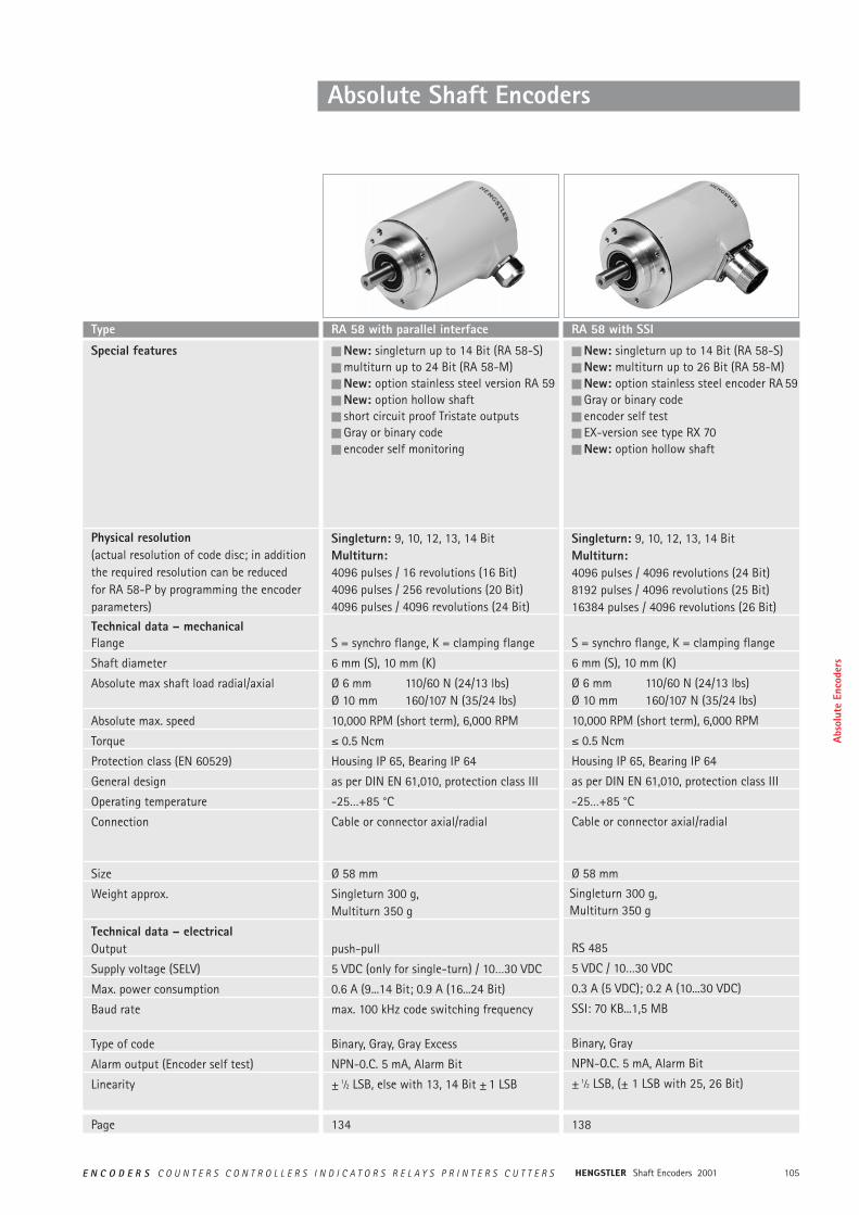
n New: singleturn up to 14 Bit (RA 58-S)n multiturn up to 24 Bit (RA 58-M)n New: option stainless steel version RA 59n New: option hollow shaftn short circuit proof Tristate outputsn Gray or binary coden encoder self monitoring
Singleturn: 9, 10, 12, 13, 14 BitMultiturn: 4096 pulses / 16 revolutions (16 Bit)4096 pulses / 256 revolutions (20 Bit)4096 pulses / 4096 revolutions (24 Bit)
S = synchro flange, K = clamping flange
6 mm (S), 10 mm (K)
Ø 6 mm 110/60 N (24/13 lbs)Ø 10 mm 160/107 N (35/24 lbs)
10,000 RPM (short term), 6,000 RPM
² 0.5 Ncm
Housing IP 65, Bearing IP 64
as per DIN EN 61,010, protection class III
-25…+85 °C
Cable or connector axial/radial
Ø 58 mm
Singleturn 300 g, Multiturn 350 g
push-pull
5 VDC (only for single-turn) / 10…30 VDC
0.6 A (9...14 Bit; 0.9 A (16...24 Bit)
max. 100 kHz code switching frequency
Binary, Gray, Gray Excess
NPN-0.C. 5 mA, Alarm Bit
± 1⁄2 LSB, else with 13, 14 Bit ± 1 LSB
n New: singleturn up to 14 Bit (RA 58-S)n New: multiturn up to 26 Bit (RA 58-M)n New: option stainless steel encoder RA 59n Gray or binary coden encoder self testn EX-version see type RX 70n New: option hollow shaft
Singleturn: 9, 10, 12, 13, 14 BitMultiturn: 4096 pulses / 4096 revolutions (24 Bit)8192 pulses / 4096 revolutions (25 Bit)16384 pulses / 4096 revolutions (26 Bit)
S = synchro flange, K = clamping flange
6 mm (S), 10 mm (K)
Ø 6 mm 110/60 N (24/13 lbs)Ø 10 mm 160/107 N (35/24 lbs)
10,000 RPM (short term), 6,000 RPM
² 0.5 Ncm
Housing IP 65, Bearing IP 64
as per DIN EN 61,010, protection class III
-25…+85 °C
Cable or connector axial/radial
Ø 58 mm
Singleturn 300 g, Multiturn 350 g
RS 485
5 VDC / 10…30 VDC
0.3 A (5 VDC); 0.2 A (10...30 VDC)
SSI: 70 KB...1,5 MB
Binary, Gray
NPN-O.C. 5 mA, Alarm Bit
± 1⁄2 LSB, (± 1 LSB with 25, 26 Bit)
Type RA 58 with parallel interface RA 58 with SSI
Absolute Shaft Encoders
Page 134 138
Abso
lute
Enc
oder
s
Shaft Encoders 2001106 E N C O D E R S C O U N T E R S C O N T R O L L E R S I N D I C A T O R S R E L A Y S P R I N T E R S C U T T E R S
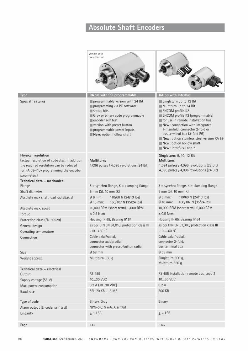
n Singleturn up to 12 Bit n Multiturn up to 24 Bit n ENCOM profile K2n ENCOM profile K3 (programmable)n for use in remote installation busn New: connection with integrated
T-manifold: connector 2-fold or bus terminal box (3-fold PG)
n New: option stainless steel version RA 59n New: option hollow shaftn New: InterBus-Loop 2
Singleturn: 9, 10, 12 BitMultiturn: 1,024 pulses / 4,096 revolutions (22 Bit)4,096 pulses / 4,096 revolutions (24 Bit)
S = synchro flange, K = clamping flange
6 mm (S), 10 mm (K)
Ø 6 mm: 110/60 N (24/13 Ibs)Ø 10 mm: 160/107 N (35/24 lbs)
10,000 RPM (short term), 6,000 RPM
² 0.5 Ncm
Housing IP 65, Bearing IP 64
as per DIN EN 61,010, protection class III
-10...+60 °C
Cable axial/radial, connector 2-fold,bus terminal box
Ø 58 mm
Singleturn 300 g, Multiturn 350 g
RS 485 installation remote bus, Loop 2
10…30 VDC
0.2 A
500 KB
Binary
± 1⁄2 LSB
RA 58 with InterBus
Absolute Shaft Encoders
n programmable version with 24 Bitn programming via PC softwaren status bitsn Gray or binary code programmablen encoder self testn version with preset buttonn programmable preset inputsn New: option hollow shaft
Multiturn: 4,096 pulses / 4,096 revolutions (24 Bit)
S = synchro flange, K = clamping flange
6 mm (S), 10 mm (K)
Ø 6 mm: 110/60 N (24/13 Ibs)Ø 10 mm: 160/107 N (35/24 lbs)
10,000 RPM (short term), 6,000 RPM
² 0.5 Ncm
Housing IP 65, Bearing IP 64
as per DIN EN 61,010, protection class III
-10…+60 °C
Cable axial/radial, connector axial/radial,connector with preset-button radial
Ø 58 mm
Multiturn 350 g
RS 485
10…30 VDC
0.2 A (10...30 VDC)
SSI: 70 KB...1.5 MB
Binary, Gray
NPN-0.C. 5 mA, Alarmbit
± 1⁄2 LSB
RA 58 with SSI programmable
Version withpreset button
Page 142 146
Special features
Physical resolution(actual resolution of code disc; in addition the required resolution can be reducedfor RA 58-P by programming the encoderparameters)
Technical data – mechanical Flange
Shaft diameter
Absolute max shaft load radial/axial
Absolute max. speed
Torque
Protection class (EN 60529)
General design
Operating temperature
Connection
Size
Weight approx.
Technical data – electricalOutput
Supply voltage (SELV)
Max. power consumption
Baud rate
Type of code
Alarm output (Encoder self test)
Linearity
Type
107E N C O D E R S C O U N T E R S C O N T R O L L E R S I N D I C A T O R S R E L A Y S P R I N T E R S C U T T E R S Shaft Encoders 2001
Absolute Shaft Encoders
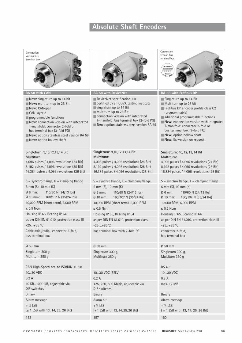
n DeviceNet specification 2.0n certified by an ODVA testing instituten singleturn up to 14 Bitn multiturn up to 26 Bitn connection version with integrated
T-manifold: bus terminal box (2-fold PG)n New: option stainless steel version RA 59
Singleturn: 9,10,12,13,14 BitMultiturn: 4,096 pulses / 4,096 revolutions (24 Bit)8,192 pulses / 4,096 revolutions (25 Bit)16,384 pulses / 4,096 revolutions (26 Bit)
S = synchro flange, K = clamping flange
6 mm (S), 10 mm (K)
Ø 6 mm: 110/60 N (24/13 Ibs)Ø 10 mm: 160/107 N (35/24 lbs)
10,000 RPM (short term), 6,000 RPM
² 0.5 Ncm
Housing IP 65, Bearing IP 64
as per DIN EN 61,010, protection class III
-25 ...+85°C
bus terminal box with 2-fold PG
Ø 58 mm
Singleturn 300 g, Multiturn 350 g
10...30 VDC (SELV)
0.2 A
125, 250, 500 Kbit/s, adjustable viaDIP switches
Binary
Alarm bit
± 1⁄2 LSB (± 1 LSB with 13, 14, 25, 26 Bit)
RA 58 with DeviceNet
152 157
n New: singleturn up to 14 bit n New: multiturn up to 26 Bit n New: CANopenn CAN layer 2n programmable functionsn New: connection version with integrated
T-manifold: connector 2-fold or bus terminal box (3-fold PG)
n New: option stainless steel version RA 59n New: option hollow shaft
Singleturn: 9,10,12,13,14 BitMultiturn: 4,096 pulses / 4,096 revolutions (24 Bit)8,192 pulses / 4,096 revolutions (25 Bit)16,384 pulses / 4,096 revolutions (26 Bit)
S = synchro flange, K = clamping flange
6 mm (S), 10 mm (K)
Ø 6 mm: 110/60 N (24/13 Ibs)Ø 10 mm: 160/107 N (35/24 lbs)
10,000 RPM (short term), 6,000 RPM
² 0.5 Ncm
Housing IP 65, Bearing IP 64
as per DIN EN 61,010, protection class III
-25…+85 °C
Cable axial/radial, connector 2-fold,bus terminal box
Ø 58 mm
Singleturn 300 g, Multiturn 350 g
CAN High-Speed acc. to ISO/DIN 11898
10...30 VDC
0.2 A
10 KB...1000 KB, adjustable viaDIP switches
Binary
Alarm message
± 1⁄2 LSB (± 1 LSB with 13, 14, 25, 26 Bit)
RA 58 with CAN
Connectionversion busterminal box
n Singleturn up to 14 Bit n Multiturn up to 26 bit n Profibus DP encoder profile class C2
(programmable)n additional programmable functionsn New: connection version with integrated
T-manifold: connector 2-fold or bus terminal box (3-fold PG)
n New: option hollow shaftn New: Ex-version on request
Singleturn: 10, 12, 13, 14 BitMultiturn: 4,096 pulses / 4,096 revolutions (24 Bit)8,192 pulses / 4,096 revolutions (25 Bit)16,384 pulses / 4,096 revolutions (26 Bit)
S = synchro flange, K = clamping flange
6 mm (S), 10 mm (K)
Ø 6 mm: 110/60 N (24/13 Ibs)Ø 10 mm: 160/107 N (35/24 Ibs)
10,000 RPM, 6,000 RPM
² 0.5 Ncm
Housing IP 65, Bearing IP 64
as per DIN EN 61,010, protection class III
-25...+85 °C
connector 2-fold, bus terminal box
Ø 58 mm
Singleturn 300 g, Multiturn 350 g
RS 485
10…30 VDC
0.2 A
max. 12 MB
Binary
Alarm message
± 1⁄2 LSB ( ± 1 LSB with 13, 14, 25, 26 Bit)
RA 58 with Profibus DP
Connectionversion busterminal box
160
Shaft Encoders 2001108 E N C O D E R S C O U N T E R S C O N T R O L L E R S I N D I C A T O R S R E L A Y S P R I N T E R S C U T T E R S
Absolute Shaft Encoders
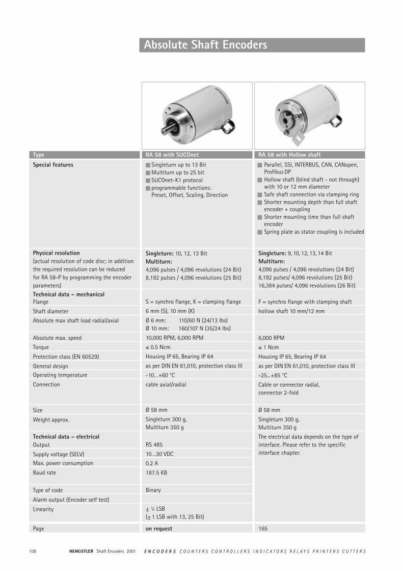
n Singleturn up to 13 Bit n Multiturn up to 25 bit n SUCOnet-K1 protocoln programmable functions:
Preset, Offset, Scaling, Direction
Singleturn: 10, 12, 13 BitMultiturn:4,096 pulses / 4,096 revolutions (24 Bit)8,192 pulses / 4,096 revolutions (25 Bit)
S = synchro flange, K = clamping flange
6 mm (S), 10 mm (K)
Ø 6 mm: 110/60 N (24/13 Ibs)Ø 10 mm: 160/107 N (35/24 Ibs)
10,000 RPM, 6,000 RPM
² 0.5 Ncm
Housing IP 65, Bearing IP 64
as per DIN EN 61,010, protection class III
-10…+60 °C
cable axial/radial
Ø 58 mm
Singleturn 300 g, Multiturn 350 g
RS 485
10…30 VDC
0.2 A
187.5 KB
Binary
± 1⁄2 LSB(± 1 LSB with 13, 25 Bit)
RA 58 with SUCOnet
on request
n Parallel, SSI, INTERBUS, CAN, CANopen,Profibus DP
n Hollow shaft (blind shaft - not through)with 10 or 12 mm diameter
n Safe shaft connection via clamping ring n Shorter mounting depth than full shaft
encoder + couplingn Shorter mounting time than full shaft
encodern Spring plate as stator coupling is included
Singleturn: 9, 10, 12, 13, 14 BitMultiturn: 4,096 pulses / 4,096 revolutions (24 Bit)8,192 pulses/ 4,096 revolutions (25 Bit)16,384 pulses/ 4,096 revolutions (26 Bit)
F = synchro flange with clamping shaft
hollow shaft 10 mm/12 mm
6,000 RPM
² 1 Ncm
Housing IP 65, Bearing IP 64
as per DIN EN 61,010, protection class III
-25...+85 °C
Cable or connector radial, connector 2-fold
Ø 58 mm
Singleturn 300 g, Multiturn 350 g
The electrical data depends on the type of interface. Please refer to the specific interface chapter.
RA 58 with Hollow shaft
165
Special features
Physical resolution(actual resolution of code disc; in addition the required resolution can be reducedfor RA 58-P by programming the encoderparameters)Technical data – mechanical Flange
Shaft diameter
Absolute max shaft load radial/axial
Absolute max. speed
Torque
Protection class (EN 60529)
General designOperating temperature
Connection
Size
Weight approx.
Technical data – electricalOutput
Supply voltage (SELV)Max. power consumption
Baud rate
Type of code
Alarm output (Encoder self test)
Linearity
Type
Page
109E N C O D E R S C O U N T E R S C O N T R O L L E R S I N D I C A T O R S R E L A Y S P R I N T E R S C U T T E R S Shaft Encoders 2001
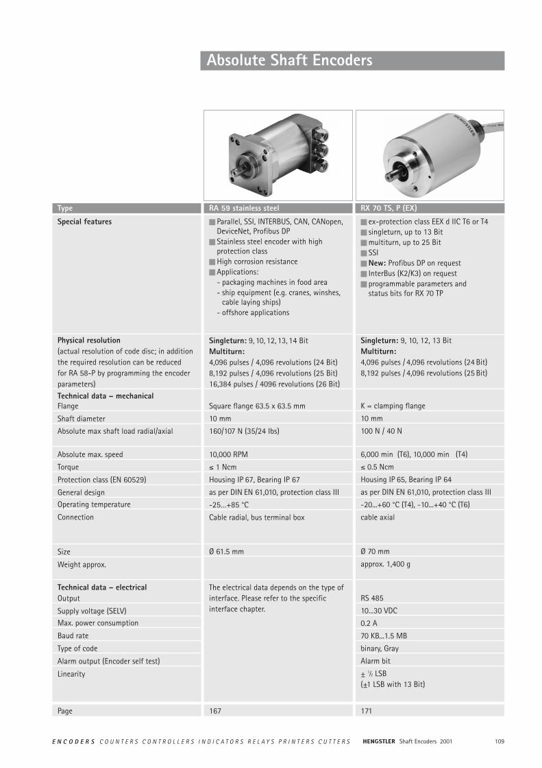
n ex-protection class EEX d IIC T6 or T4n singleturn, up to 13 Bitn multiturn, up to 25 Bitn SSIn New: Profibus DP on requestn InterBus (K2/K3) on requestn programmable parameters and
status bits for RX 70 TP
Singleturn: 9, 10, 12, 13 BitMultiturn: 4,096 pulses / 4,096 revolutions (24 Bit)8,192 pulses / 4,096 revolutions (25 Bit)
K = clamping flange
10 mm
100 N / 40 N
6,000 min (T6), 10,000 min (T4)
² 0.5 Ncm
Housing IP 65, Bearing IP 64
as per DIN EN 61,010, protection class III
-20...+60 °C (T4), -10...+40 °C (T6)
cable axial
Ø 70 mm
approx. 1,400 g
RS 485
10...30 VDC
0.2 A
70 KB...1.5 MB
binary, Gray
Alarm bit
± 1⁄2 LSB(±1 LSB with 13 Bit)
RX 70 TS, P (EX)
Absolute Shaft Encoders
167 171
n Parallel, SSI, INTERBUS, CAN, CANopen,DeviceNet, Profibus DP
n Stainless steel encoder with high protection class
n High corrosion resistancen Applications:
- packaging machines in food area- ship equipment (e.g. cranes, winshes,
cable laying ships)- offshore applications
Singleturn: 9, 10, 12, 13, 14 BitMultiturn: 4,096 pulses / 4,096 revolutions (24 Bit)8,192 pulses / 4,096 revolutions (25 Bit)16,384 pulses / 4096 revolutions (26 Bit)
Square flange 63.5 x 63.5 mm
10 mm
160/107 N (35/24 Ibs)
10,000 RPM
² 1 Ncm
Housing IP 67, Bearing IP 67
as per DIN EN 61,010, protection class III
-25…+85 °C
Cable radial, bus terminal box
Ø 61.5 mm
The electrical data depends on the type of interface. Please refer to the specific interface chapter.
RA 59 stainless steel
Special features
Physical resolution(actual resolution of code disc; in addition the required resolution can be reducedfor RA 58-P by programming the encoderparameters)Technical data – mechanical Flange
Shaft diameter
Absolute max shaft load radial/axial
Absolute max. speed
Torque
Protection class (EN 60529)
General designOperating temperature
Connection
Size
Weight approx.
Technical data – electricalOutput
Supply voltage (SELV)Max. power consumption
Baud rate
Type of code
Alarm output (Encoder self test)
Linearity
Type
Page
Shaft Encoders 2001110 E N C O D E R S C O U N T E R S C O N T R O L L E R S I N D I C A T O R S R E L A Y S P R I N T E R S C U T T E R S
Absolute Shaft Encoders
ABSOLUTE SHAFT ENCODERSARE DIVIDED INTO:
OPTOELECTRONIC METHOD OFMEASUREMENT
Multiturn type
Singleturn type One revolution (= 360°) is encoded into nincrements. The codes repeat for a rotationof more than 360°.
As well as measuring 360° (one revolution)this type can encode additional revoluti-ons. This is necessary if the number ofincrements of a singleturn shaft encoder isnot large enough, for example for long tra-verses, or a larger number of incrementsper revolution than possible with a single-turn encoder.
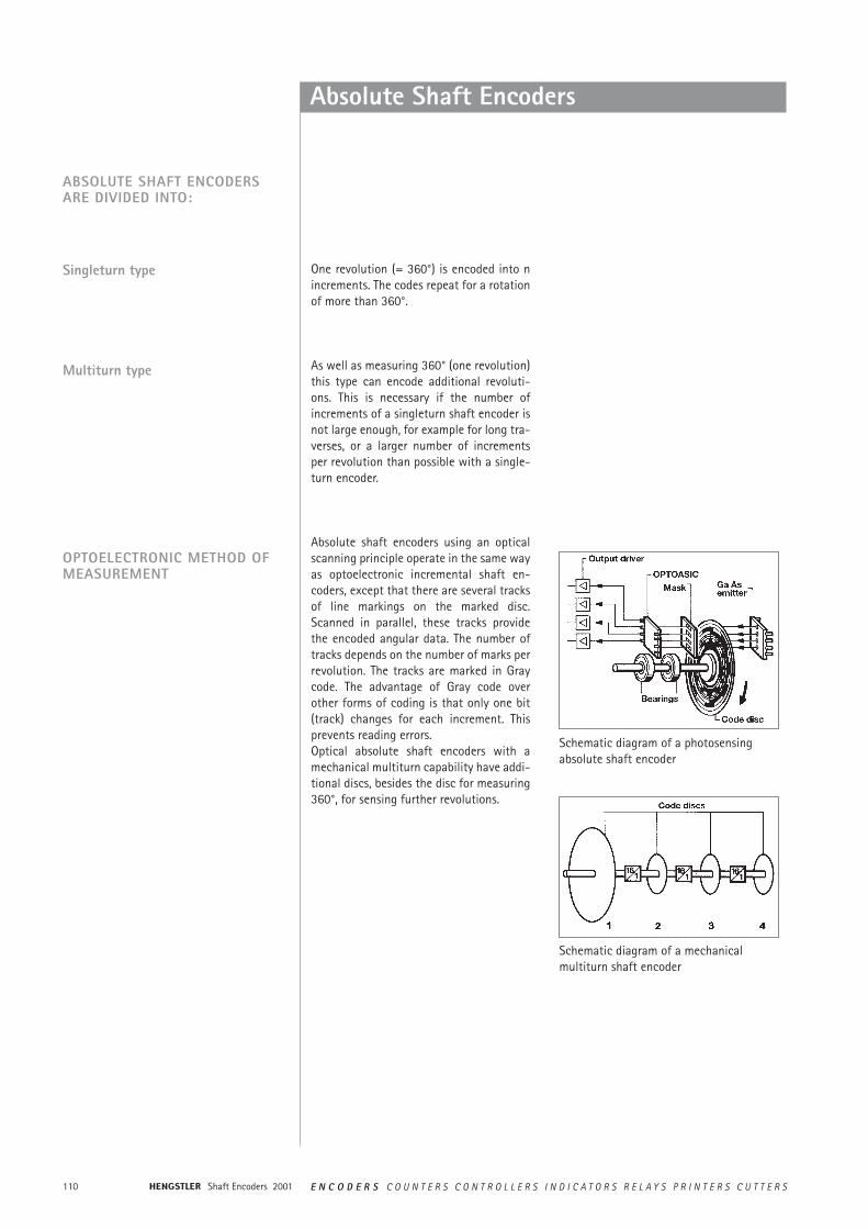
Absolute shaft encoders using an opticalscanning principle operate in the same wayas optoelectronic incremental shaft en-coders, except that there are several tracksof line markings on the marked disc.Scanned in parallel, these tracks providethe encoded angular data. The number oftracks depends on the number of marks perrevolution. The tracks are marked in Graycode. The advantage of Gray code overother forms of coding is that only one bit(track) changes for each increment. Thisprevents reading errors.Optical absolute shaft encoders with amechanical multiturn capability have addi-tional discs, besides the disc for measuring360°, for sensing further revolutions.
Schematic diagram of a photosensingabsolute shaft encoder
Schematic diagram of a mechanicalmultiturn shaft encoder

111E N C O D E R S C O U N T E R S C O N T R O L L E R S I N D I C A T O R S R E L A Y S P R I N T E R S C U T T E R S Shaft Encoders 2001
High-Tech Features in a Modular System
Of course, the user has a selection of themost advanced interface technology avai-lable:
• Tristate parallel driversThe symmetrical push-pull drivers are fully short circuit proof, overload protectedand polarity protected in a range from 10to 30 V.Parallel bus systems are easy to realize.So you save in cabling expenses.
• CANBus specifications according to CAN High-Speed ISO/DIS 11898 for transfer rates upto 1 MBaud.
INNOVATIVE TECHNOLOGY
INTERFACES
APPLICATIONS
PROGRAMMABLEABSOLUTE SHAFT ENCODERS
Hengstler’s RA series comprises a completerange of absolute encoders, all in OPTOASICtechnology.OPTOASIC units combine all required opticaland electronic components in only one sili-con chip.
This new technology is tailored to the user’sneeds and offers advantages previouslyunknown in the field:- High degree of reliability
due to differential scanning and single-step Gray code.
- Fail-safe due to the elimination of morethan a hundred components
- Long serviceable lifetime due to state-of-the-art semiconductor technology-
All essential parameters are userpro-grammable.Additional advantages are uncomplicatedsubsequent data processing, electronicadjustment and add-on optimization ofmechanical systems which are subject totolerances.
The new encoders are, for example, perfectlysuited to determine angular positions inautomated systems with reliable and preciseoperation.Absolute encoding eliminates the need for areference run after interruptions (such aspower failures).
- High degree of electromagnetic compa-tibility due to elimination of macroscopiclow-current paths.
Our new absolute shaft encoders have anexcellent cost/performance ratio. As a furt-her feature the encoders are fully inter-changeable due to identical externaldimensions and mechanical design ofmounts.
This makes it easy for the user to switchfrom incremental shaft encoders to abso-lute shaft encoders.
Furthermore, storage and maintenance aremore cost-efficient: the same encoder maybe used for a variety of applications andassigned to its task at the place of installa-tion.
Examples of applications are:Conveyor systems, robots, elevators, camswitching devices, valve positioning, rotaryindexing tables, angle measurement or anglesynchronization (swivelling equipment inassembly lines, feed drives).
• INTERBUSInterface including the potential-freepower supply is already integrated in thehousing with a diameter of only 58 mm.
• SSIThe encoders can also be supplied withsynchronous-serial interface (SSI) whichis available worldwide.This allows trouble-free connection tocommercial processing components.
• Profibus DPProtocol according to encoder profile classC2 (programmable)
Shaft Encoders 2001112 E N C O D E R S C O U N T E R S C O N T R O L L E R S I N D I C A T O R S R E L A Y S P R I N T E R S C U T T E R S
Synchronous-serial Transfer
GENERAL ASPECTS In many cases, absolute shaft encoders aresubject to severe mechanical stresses and toelectrical and magnetic fields that contami-nate the site.Therefore, special design measures are neededto combat dirt, dust and liquids in industrialenvironments.Our absolute shaft encoders are of state-of-the-art rugged mechanical construction, andthe electronic components are very compact.A main consideration for immunity to inter-ference is the data transfer from the shaftencoder to the control system. The controlsystem must be able to read the readingsfrom the shaft encoder without errors. Underno circumstances should undefined data betransmitted, for example at the changeoverpoint.
The major differences between the conceptof synchronous-serial data transfer for abso-lute shaft encoders described here and paral-lel and asynchronous serial forms of datatransfer are:• less electronic components• less cabling for data transfer• the same interface hardware, regardless
of the absolute shaft encoder’s resolution(word length)
• electrical insulation of the shaft encoderfrom the control system by optocouplers
• open-circuit monitoring by constant cur-rent
• data transfer rates up to 1.5 megabits persecond (depending on the length of line)
• ring-register operating possible.
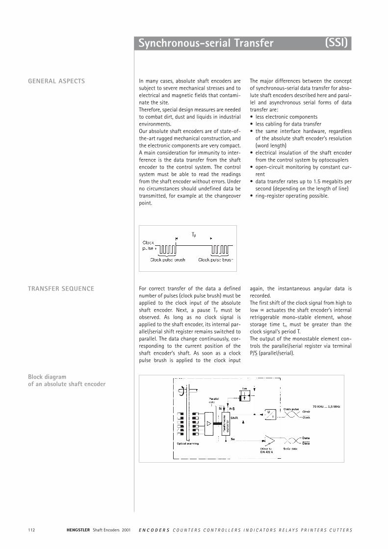
For correct transfer of the data a definednumber of pulses (clock pulse brush) must beapplied to the clock input of the absoluteshaft encoder. Next, a pause TP must beobserved. As long as no clock signal isapplied to the shaft encoder, its internal par-allel/serial shift register remains switched toparallel. The data change continuously, cor-responding to the current position of theshaft encoder’s shaft. As soon as a clockpulse brush is applied to the clock input
again, the instantaneous angular data isrecorded.The first shift of the clock signal from high tolow ° actuates the shaft encoder’s internalretriggerable mono-stable element, whosestorage time tm must be greater than theclock signal’s period T.The output of the monostable element con-trols the parallel/serial register via terminalP/S (parallel/serial).
Block diagramof an absolute shaft encoder
TRANSFER SEQUENCE
(SSI)
70 KHz ... 1,5 MHz
113E N C O D E R S C O U N T E R S C O N T R O L L E R S I N D I C A T O R S R E L A Y S P R I N T E R S C U T T E R S Shaft Encoders 2001
Synchronous-serial Transfer
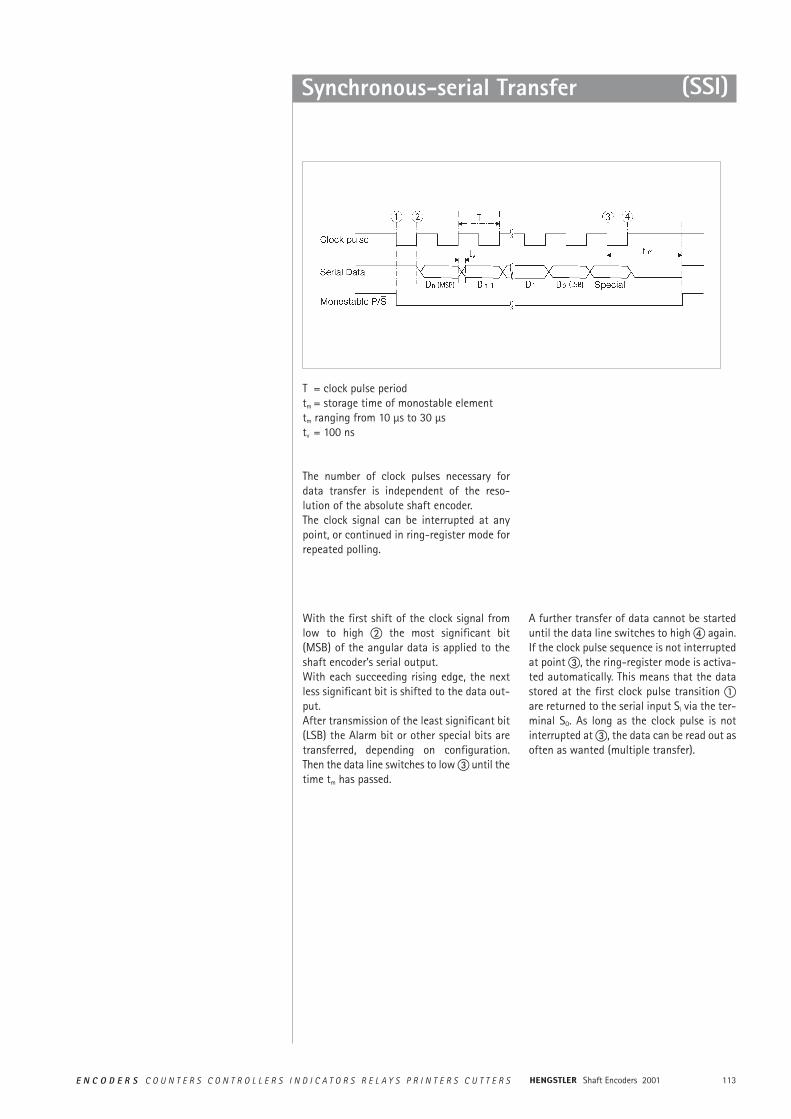
With the first shift of the clock signal fromlow to high b the most significant bit(MSB) of the angular data is applied to theshaft encoder’s serial output.With each succeeding rising edge, the nextless significant bit is shifted to the data out-put.After transmission of the least significant bit(LSB) the Alarm bit or other special bits aretransferred, depending on configuration.Then the data line switches to low c until thetime tm has passed.
A further transfer of data cannot be starteduntil the data line switches to high d again.If the clock pulse sequence is not interruptedat point c, the ring-register mode is activa-ted automatically. This means that the datastored at the first clock pulse transition aare returned to the serial input Si via the ter-minal SO. As long as the clock pulse is notinterrupted at c, the data can be read out asoften as wanted (multiple transfer).
T = clock pulse periodtm = storage time of monostable elementtm ranging from 10 µs to 30 µstv = 100 ns
The number of clock pulses necessary fordata transfer is independent of the reso-lution of the absolute shaft encoder.The clock signal can be interrupted at anypoint, or continued in ring-register mode forrepeated polling.
(SSI)
Shaft Encoders 2001114 E N C O D E R S C O U N T E R S C O N T R O L L E R S I N D I C A T O R S R E L A Y S P R I N T E R S C U T T E R S
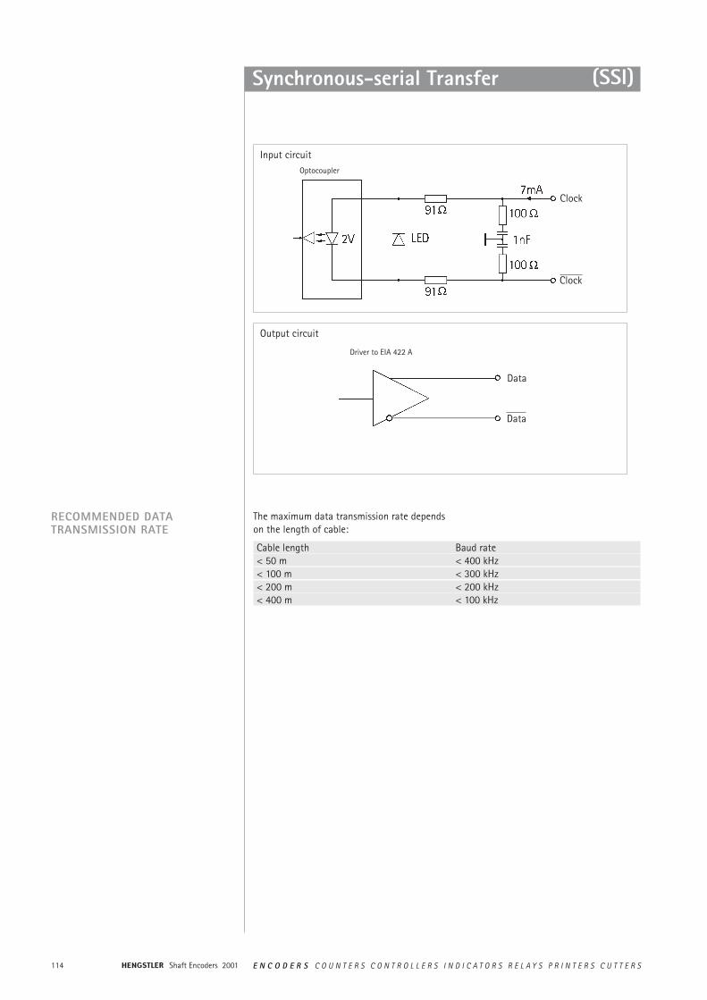
Synchronous-serial Transfer
RECOMMENDED DATA TRANSMISSION RATE
Cable length Baud rate< 50 m < 400 kHz< 100 m < 300 kHz< 200 m < 200 kHz< 400 m < 100 kHz
The maximum data transmission rate dependson the length of cable:
(SSI)
Input circuit
Output circuit
Driver to EIA 422 A
Optocoupler
Data
Data
Clock
Clock
115E N C O D E R S C O U N T E R S C O N T R O L L E R S I N D I C A T O R S R E L A Y S P R I N T E R S C U T T E R S Shaft Encoders 2001
INTERBUS
WHAT ARE THE BENEFITS OFINTERBUS COMPARED WITH ACONVENTIONAL SYSTEMWIRING?
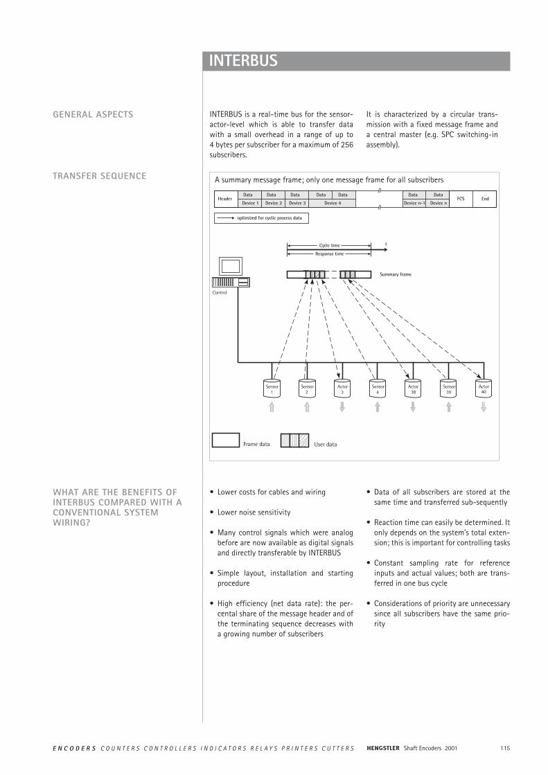
INTERBUS is a real-time bus for the sensor-actor-level which is able to transfer datawith a small overhead in a range of up to 4 bytes per subscriber for a maximum of 256subscribers.
It is characterized by a circular trans-mission with a fixed message frame and a central master (e.g. SPC switching-inassembly).
• Lower costs for cables and wiring
• Lower noise sensitivity
• Many control signals which were analogbefore are now available as digital signalsand directly transferable by INTERBUS
• Simple layout, installation and startingprocedure
• High efficiency (net data rate): the per-cental share of the message header and ofthe terminating sequence decreases witha growing number of subscribers
• Data of all subscribers are stored at thesame time and transferred sub-sequently
• Reaction time can easily be determined. Itonly depends on the system’s total exten-sion; this is important for controlling tasks
• Constant sampling rate for referenceinputs and actual values; both are trans-ferred in one bus cycle
• Considerations of priority are unnecessarysince all subscribers have the same prio-rity
GENERAL ASPECTS
TRANSFER SEQUENCE A summary message frame; only one message frame for all subscribers
Shaft Encoders 2001116 E N C O D E R S C O U N T E R S C O N T R O L L E R S I N D I C A T O R S R E L A Y S P R I N T E R S C U T T E R S
INTERBUS
ENCOM USER GROUP
• No system-parameter definition beforestarting procedure
• Data integrity is secured by 16-bit-CRC(according to CCITT polynomial) done foreach transmission
• Sophisticated diagnostic software for thecentral bus controller: a point of error canspecifically be isolated; in each case ofmalfunction there is a possibility to closethe circular system in every single bus clip.
Devices with an INTERBUS interface for pro-cess control are now available from morethan 200 manufacturers.
Encoder manufacturers are joined togetherin the ENCOM user group; drive manu-facturers in DRIVECOM.
The user groups shall maximize the benefitfor the customer by standardization of datatransmission.
There is a high availability of devices withINTERBUS interface, and the bus mode hasalready been successful in industrial use.
The following device classes defined byENCOM are used for absolute shaftencoders:
Class 2 (K2):• 32-bit process data• Binary• Right-justified• Readable only• No control bits or status bits
Class 3 (K3):• 32-bit process data• Coded according to manufacturer
specifications• Right-justified• 7 status bits and control bits
117E N C O D E R S C O U N T E R S C O N T R O L L E R S I N D I C A T O R S R E L A Y S P R I N T E R S C U T T E R S Shaft Encoders 2001
INTERBUS
TECHNICAL DATA
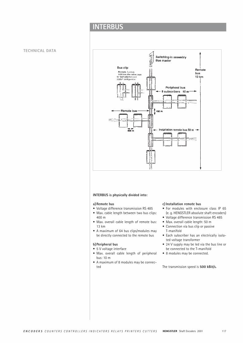
INTERBUS is physically divided into:
a)Remote bus• Voltage difference transmission RS 485• Max. cable length between two bus clips:
400 m• Max. overall cable length of remote bus:
13 km• A maximum of 64 bus clips/modules may
be directly connected to the remote bus
b)Peripheral bus• 5 V voltage interface• Max. overall cable length of peripheral
bus: 10 m• A maximum of 8 modules may be connec-
ted
c) Installation remote bus• For modules with enclosure class IP 65
(e. g. HENGSTLER absolute shaft encoders)• Voltage difference transmission RS 485• Max. overall cable length: 50 m• Connection via bus clip or passive
T-manifold• Each subscriber has an electrically isola-
ted voltage transformer• 24 V supply may be led via the bus line or
be connected to the T-manifold• 8 modules may be connected.
The transmission speed is 500 kBit/s.
Shaft Encoders 2001118 E N C O D E R S C O U N T E R S C O N T R O L L E R S I N D I C A T O R S R E L A Y S P R I N T E R S C U T T E R S
INTERBUS
INTERBUS DIAGNOSTIC CONCEPT
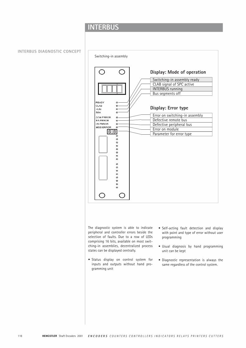
The diagnostic system is able to indicateperipheral and controller errors beside theselection of faults. Due to a row of LEDscomprising 16 bits, available on most swit-ching-in assemblies, decentralized processstates can be displayed centrally.
• Status display on control system forinputs and outputs without hand pro-gramming unit
• Self-acting fault detection and displaywith point and type of error without userprogramming
• Usual diagnosis by hand programmingunit can be kept
• Diagnostic representation is always thesame regardless of the control system.
Switching-in assembly
Display: Mode of operation
Display: Error type
Switching-in assembly readyCLAB signal of SPC active
Bus segments offINTERBUS running
Error on switching-in assemblyDefective remote bus
Error on moduleParameter for error type
Defective peripheral bus
119E N C O D E R S C O U N T E R S C O N T R O L L E R S I N D I C A T O R S R E L A Y S P R I N T E R S C U T T E R S Shaft Encoders 2001
INTERBUS-Loop
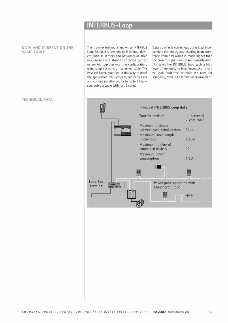
This transfer method is known as INTERBUSLoop. Using this technology, individual devi-ces such as sensors and actuators or drivemechanisms and absolute encoders can benetworked together in a ring configuration,using simple 2-core, un-screened cable. ThePhysical Layer, modified in this way to meetthe application requirements, can carry dataand current simultaneously to up to 63 sen-sors, using a cable with just 2 cores.
Data transfer is carried out using load-inde-pendent current signals resulting in an inter-fence immunity which is much higher thanthe current signals which are normally used.This gives the INTERBUS Loop such a highlevel of immunity to interfences, that it canbe used fault-free, without the need forscreening, even in an industrial environment.
DATA AND CURRENT ON THESAME CABLE
TECHNICAL DATA
Principal INTERBUS Loop data
Transfer medium un-screened2-core cable
Maximum distancebetween connected devices 10 mMaximum cable lengthin one loop 100 mMaximum number ofconnected devices 32Maximum power consumption 1.5 A
Loop Busterminal
Power pulse operation withManchester Code
Shaft Encoders 2001120 E N C O D E R S C O U N T E R S C O N T R O L L E R S I N D I C A T O R S R E L A Y S P R I N T E R S C U T T E R S
INTERBUS-Loop
Extending the INTERBUS by the addition ofthe INTERBUS Loop has made it possible tofully network automation system configura-tions, right through from the sensors andactuators up to the controller level. TheINTERBUS Loop uses the normed InterBusprotocol to connect analogue and digitalsensors and actuators using a simple 2-corecable, which provides the power supply atthe same time. This gives users of automa-tion technology and economical alternativeto parallel cabling between the InterBus I/Omodules and the sensors and actuators. Withnewly developed fast connection technology,the bus cable can be connected quickly andsecurely without using any tools.
The tried and tested, highly efficient DIN E19258 INTERBUS protocol is also used withthe INTERBUS Loop. Only the physical cha-racteristics for the parallel transfer of dataand power have changed. This however istransparent to the user when he is program-ming his installation. Using the knownINTERBUS IBS-CMD tool, data such as theManufacturer's name, the Product codenumber, etc., can be displayed without pro-blem, for all the individual modules and for allthe sensors and actuators in the INTERBUSLoop.
All the user needs to build up the INTERBUSLoop is the INTERBUS Loop terminal, whichconverts the RS485 signals into Manchestercoded, interference-immune current signals.
This bus terminal operates exactly the sameas a standard bus terminal and can be usedto integrate the loop into any INTERBUSLoop installation. At only 500Kbit/sec, scan-ning is reliably fast and equidistant. Transferis so secure that it can be used for directmachine applications without any problem.With the high number of INTERBUS interfacemodules available, INTERBUS Loop can beused with most common control systemsincluding the internationally used PC stan-dard.
Even single-bit sensors can be integratedsince each sensor only occupies just as manybits as it needs for the special function it iscarrying out at the time. No special powerunits are necessary.
If a user needs to integrate more sensors oractuators, as usual with INTERBUS, he simplyinserts a new bus terminal. Because of thehigh number of stations which can beconnected (up to 63 depending on powerconsumption), bus terminals never need tobe a cost consideration. Furthermore, theuser doesn't need to assign addresses sincethe system is automatically informed,through the position of the sensor of actua-tor and the way in which it is addressed.
GENERAL INFORMATION
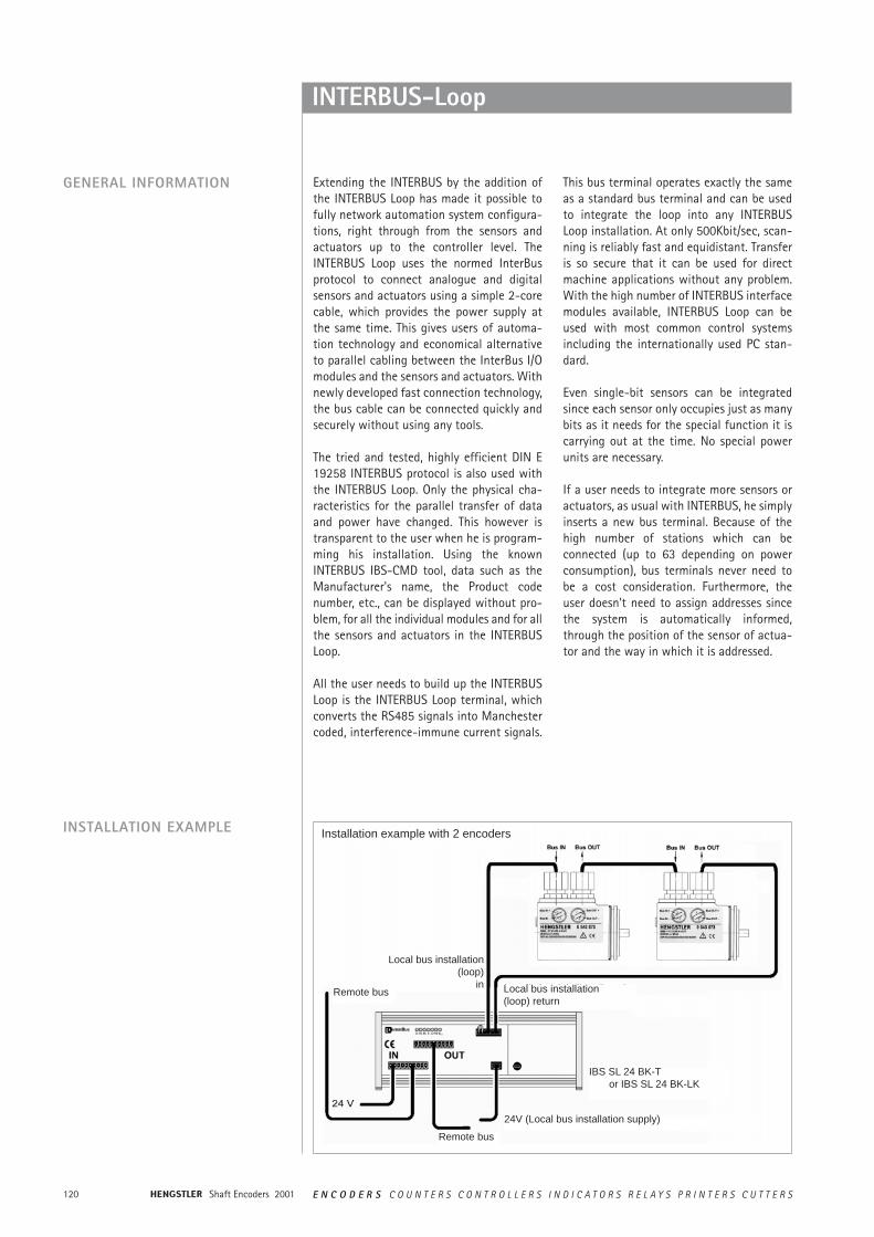
INSTALLATION EXAMPLE Installation example with 2 encoders
Local bus installation(loop)
in Local bus installation(loop) return
Remote bus
Remote bus
24V (Local bus installation supply)
IBS SL 24 BK-Tor IBS SL 24 BK-LK
121E N C O D E R S C O U N T E R S C O N T R O L L E R S I N D I C A T O R S R E L A Y S P R I N T E R S C U T T E R S Shaft Encoders 2001
CAN
GENERAL INFORMATIONINTRODUCTION
FIELD OF APPLICATION
The RA58 is an absolute shaft encoder(encoder, angle encoder). The version descri-bed in this technical manual sends its cur-rent position to another station via the"CAN-bus" transmission medium (physically:screened and twisted two-wire line).The serial bus system CAN (Controller AreaNetwork), which had been originally develo-ped by Bosch/ Intel for automotive uses, isgaining ground in industrial automationtechnology. The system is multimaster-com-patible, i.e. several CAN- stations are able torequest the bus at the same time. The mes-sage with the highest priority (determinedby the identifier) will be received immediately.The data transfer is regulated by the messa-ge's priority. Within the CAN system, thereare no transport addresses, but messageidentifiers. The message which is being sentcan be received by all stations at the sametime (broadcast). By means of a special fil-ter methods, the station only accepts therelevant messages. The identifier transmit-ted with the message is the basis for thedecision as to whether the message will beaccepted or not.
The bus coupler is standardised according tothe international standard ISO-DIS 11898(CAN High Speed) standard and allows datato be transferred at a maximum rate of 1MBit/ s. The most significant feature of theCAN-protocol is its high level of transmis-sion reliability (Hamming distance = 6).The CAN-Controller Intel 82527 used in the encoder is basic as well as full-CANcompatible and supports the CAN-specifi-cation 2.0 part B (standard protocol with11-bit- identifier as well as extended pro-tocol with 29-bit identifier). Up to now,only 11-bit identifiers have been used forCANopen.
In systems, where the position of a drive or ofany other part of a machine has to be recor-ded and signalled to the control system, theRA58 can assume this function. The RA58can resolve, for instance, positioning tasksby sending the check-back signal concerningthe present drive position via the CAN bus tothe positioning unit.
Shaft Encoders 2001122 E N C O D E R S C O U N T E R S C O N T R O L L E R S I N D I C A T O R S R E L A Y S P R I N T E R S C U T T E R S
CAN
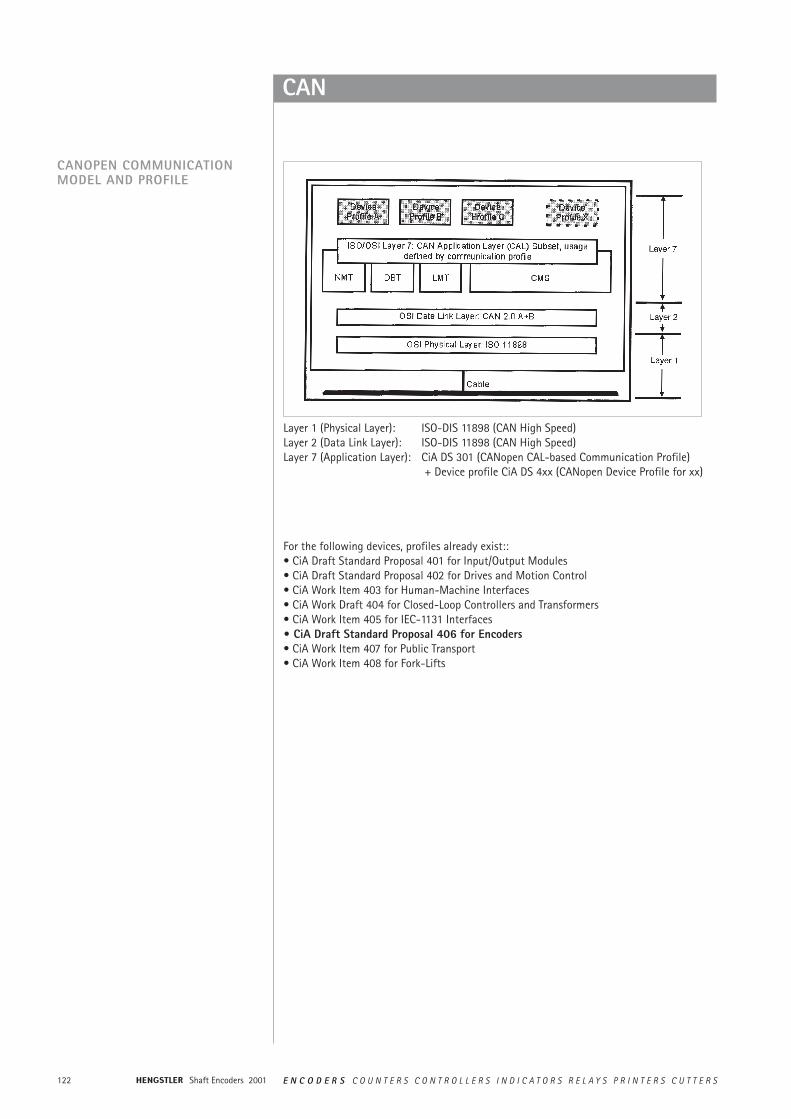
CANOPEN COMMUNICATIONMODEL AND PROFILE
For the following devices, profiles already exist::• CiA Draft Standard Proposal 401 for Input/Output Modules• CiA Draft Standard Proposal 402 for Drives and Motion Control• CiA Work Item 403 for Human-Machine Interfaces• CiA Work Draft 404 for Closed-Loop Controllers and Transformers• CiA Work Item 405 for IEC-1131 Interfaces• CiA Draft Standard Proposal 406 for Encoders• CiA Work Item 407 for Public Transport• CiA Work Item 408 for Fork-Lifts
Layer 1 (Physical Layer): ISO-DIS 11898 (CAN High Speed)Layer 2 (Data Link Layer): ISO-DIS 11898 (CAN High Speed)Layer 7 (Application Layer): CiA DS 301 (CANopen CAL-based Communication Profile)
+ Device profile CiA DS 4xx (CANopen Device Profile for xx)
123E N C O D E R S C O U N T E R S C O N T R O L L E R S I N D I C A T O R S R E L A Y S P R I N T E R S C U T T E R S Shaft Encoders 2001
CAN
THE CANOPEN PROFILE
THE ENCODER DEVICE PROFILE(CIA DSP 406)
About two and a half years after the CiA, theassociation of the user and manufacturer ofCAN products, had adopted the CANApplication Layer (CAL), CANopen and therespective device profiles paved the way forthe development of open systems.CANopen has been developed under thetechnical direction of the Steinbeis TransferCentre for Automation (STA Reutlingen;Germany) on the basis of the layer 7 CALspecification.Compared with CAL, CANopen only providesthe functions needed for this special pur-pose. CANopen is thus a part of CAL whichhas been optimised for application purposesand allows for a simpler system structure aswell as for simpler devices.CANopen has been optimised for a quicktransfer of data in real-time systems and hasbeen standardised for different device profi-les.The CAN in Automation (CiA) association ofusers and manufacturers is responsible forthe establishing and the standardisation ofthe respective profiles.The RA58 with CANopen meets the require-ments laid down in the communication pro-file (CiA DS 301) and in the device profile forencoders.
CANopen allows for:• autoconfiguration of the network,• comfortable access to all device
parameters.• synchronisation of the devices,• cyclical and event-controlled process
data processing,• simultaneous data input and output.
CANopen uses four communication objects(COB) with different features:• Process Data Objects (PDO) for
real-time data• Service Data Objects (SDO) for the
transfer of parameters and programs• Network Management (NMT,
Life-Guarding)• predefined objects (for synchronisation,
time stamp, emergency message)
All device parameters are stored in an objectdirectory. The object directory contains thedescription, data type and structure of theparameters as well as their addresses (index).The directory consists of three parts: com-munication profile parameters, device profileparameters and manufacturer specific para-meters.
This profile describes a binding, but manu-facturer-independent definition of the inter-face for encoders. The profile not only defi-nes which CANopen functions are to beused, but also how they are to be used. Thisstandard permits an open and manufactu-rer-independent bus system.
The device profile consists of two objectcategories• the standard category C1 describes all
the basic functions the shaft encoder must contain
• the extended category C2 contains a variety of additional functions which either have to be supported by category C2 shaft encoders (mandatory) or which are optional. Category C2 devices thus contain all C1 and C2 mandatory functions as wellas, depending on the manufacturer, further optional functions.
Furthermore, an addressable area is defined inthe profile, to which, depending on themanufacturer, different functions can beassigned.
Shaft Encoders 2001124 E N C O D E R S C O U N T E R S C O N T R O L L E R S I N D I C A T O R S R E L A Y S P R I N T E R S C U T T E R S
CAN
DATA TRANSFER
COB IDENTIFIER
NODE NUMBER
In CANopen, the data is transferred bymeans of two different communicationtypes (COB = Communication Object) withdifferent features:
• Process Data Objects (PDO)• Service Data Objects (SDO)
The priority of the message objects is deter-mined by the COB identifier.
The process data objects (PDO) serve thehighly dynamic exchange of real-time data(e.g. position of the shaft encoder) with amaximum length of 8 Byte. This data istransferred with high priority (low COB iden-tifier). PDOs are broadcast messages and puttheir information simultaneously at the dis-posal of all desired receivers.
The service data objects (SDO) form thecommunication channel for the transfer ofdevice parameters (e.g. programming of theshaft encoders' resolution). Since theseparameters are transferred acyclically (e.g.only once when running up the network), theSDO objects have a low priority (high COBidentifier).
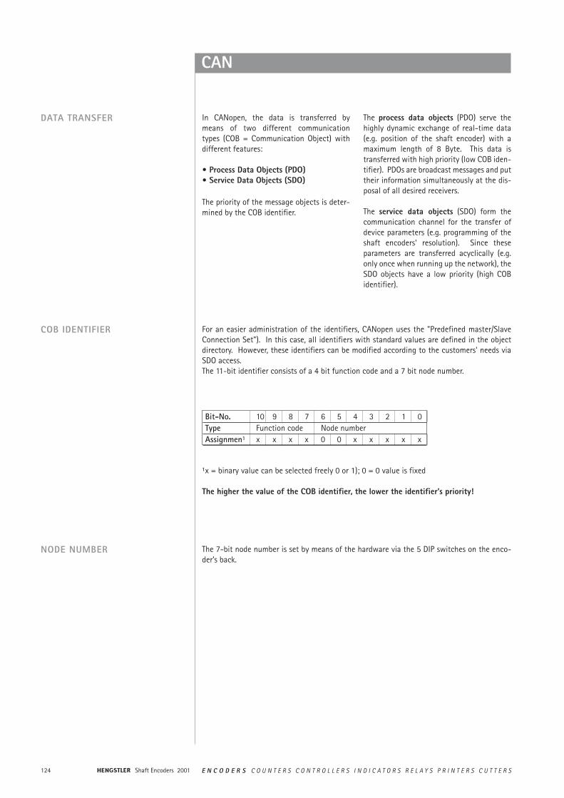
For an easier administration of the identifiers, CANopen uses the "Predefined master/SlaveConnection Set"). In this case, all identifiers with standard values are defined in the objectdirectory. However, these identifiers can be modified according to the customers' needs viaSDO access. The 11-bit identifier consists of a 4 bit function code and a 7 bit node number.
Bit-No. 10 9 8 7 6 5 4 3 2 1 0Type Function code Node numberAssignmen1 x x x x 0 0 x x x x x
1x = binary value can be selected freely 0 or 1); 0 = 0 value is fixed
The higher the value of the COB identifier, the lower the identifier’s priority!
The 7-bit node number is set by means of the hardware via the 5 DIP switches on the enco-der’s back.
125E N C O D E R S C O U N T E R S C O N T R O L L E R S I N D I C A T O R S R E L A Y S P R I N T E R S C U T T E R S Shaft Encoders 2001
DeviceNet
Background• The basic technology was developed by
Allen-Bradley• Introduced in March 1994• The ODVA (Open DeviceNet Vendor
Association) was founded in April 1995
Technology• CAN-Layer 2 (Data Link Layer) - ISO 11898
and 11519-1• DeviceNet covers layer 7 (Application
Layer) and layer 1 (Physical Layer), develo-ped for industrial automation
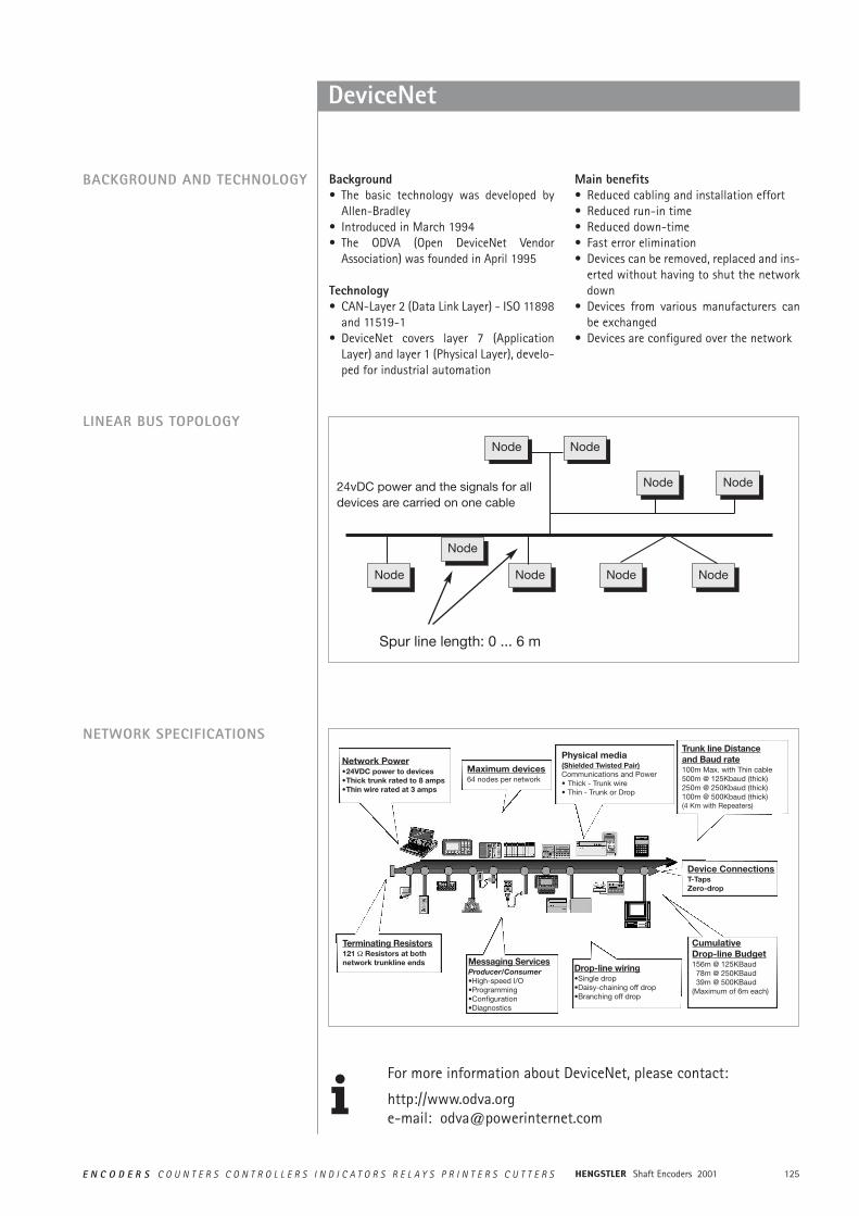
24vDC power and the signals for alldevices are carried on one cable
KnotenNode KnotenNode
KnotenNode KnotenNode
KnotenNodeKnotenNodeKnotenNode
KnotenNode
KnotenNode
Spur line length: 0 ... 6 m
Main benefits• Reduced cabling and installation effort• Reduced run-in time• Reduced down-time• Fast error elimination• Devices can be removed, replaced and ins-
erted without having to shut the networkdown
• Devices from various manufacturers canbe exchanged
• Devices are configured over the network
NETWORK SPECIFICATIONS
Maximum devices64 nodes per network
Network Power•24VDC power to devices•Thick trunk rated to 8 amps•Thin wire rated at 3 amps
Physical media(Shielded Twisted Pair)Communications and Power• Thick - Trunk wire• Thin - Trunk or Drop
Device ConnectionsT-TapsZero-drop
CumulativeDrop-line Budget156m @ 125KBaud78m @ 250KBaud39m @ 500KBaud
(Maximum of 6m each)
Trunk line Distanceand Baud rate100m Max. with Thin cable500m @ 125Kbaud (thick)250m @ 250Kbaud (thick)100m @ 500Kbaud (thick)(4 Km with Repeaters)
Drop-line wiring•Single drop•Daisy-chaining off drop•Branching off drop
Messaging ServicesProducer/Consumer•High-speed I/O•Programming•Configuration•Diagnostics
Terminating Resistors121 ½ Resistors at bothnetwork trunkline ends
For more information about DeviceNet, please contact:
http://www.odva.orge-mail: [email protected]
BACKGROUND AND TECHNOLOGY
LINEAR BUS TOPOLOGY
Shaft Encoders 2001126 E N C O D E R S C O U N T E R S C O N T R O L L E R S I N D I C A T O R S R E L A Y S P R I N T E R S C U T T E R S
Profibus-DP
GENERAL INFORMATION The basic functions of the PROFIBUS DP are here only described in extracts. For addi-tional information, please refer to the stan-dards on PROFIBUS DP, i.e. DIN 19245-3 andEN 50170 respectively.
INTRODUCTION The RA 58 is an absolute shaft encoder(encoder, angle encoder). The version descri-bed in this manual sends its current positionto another station via the transmissionmedium "PROFIBUS DP" (physically: scree-ned and twisted pair line). The RA 58 sup-ports all class 1 and 2 functions listed in theencoder profile.
PROFIBUS-DP is manufacturer independent,open field bus standard for a variety ofapplications in the field of production, processand building services automation. The requi-rements of openness and independence fromthe manufacturer are stipulated in theEuropean standard EN 50 170. PROFIBUS-DP
permits the communication of devices pro-duced by different manufacturers withoutany particular adaptations of the interfaces.PROFIBUS DP is a special standard versionfor a quick data exchange within the fieldlevel which has been optimised in terms ofspeed and low connection costs. Centralcontrol systems like, for example SPC/ PCcommunicate via a quick, serial connectionwith local field devices like drives, valves, orencoders. The data exchange between thesedevices is predominantly cyclical. The com-munication functions required for thisexchange are determined by the basic func-tions of the PROFIBUS DP according to theEN 50 170 European standard.
FIELD OF APPLICATION In systems, where the position of a drive or ofany other part of a machine has to be recor-ded and signalled to the control system, theRA58 can assume this function. The RA58
can resolve, for instance, positioning tasksby sending the checkback signal concerningthe present drive position via the PROFIBUSDP to the positioning unit.
BASIC FUNCTIONS OF THE PROFIBUS DP
The central control system (master) cycli-cally reads out the input information fromthe slaves and writes the output informationto the slaves. For this purpose, the bus cycletime has to be shorter than the programcycle time of the central SPC, which amo-unts to approx. 10 ms for various applications.Apart from the cyclical user data transfer,
the PROFIBUS DP version also disposes ofpowerful functions for diagnosis and initialoperation procedures. The data traffic iscontrolled by watchdog functions on boththe slave and the master side. The followingtable summarises the basic functions of thePROFIBUS DP.
127E N C O D E R S C O U N T E R S C O N T R O L L E R S I N D I C A T O R S R E L A Y S P R I N T E R S C U T T E R S Shaft Encoders 2001
Profibus-DP
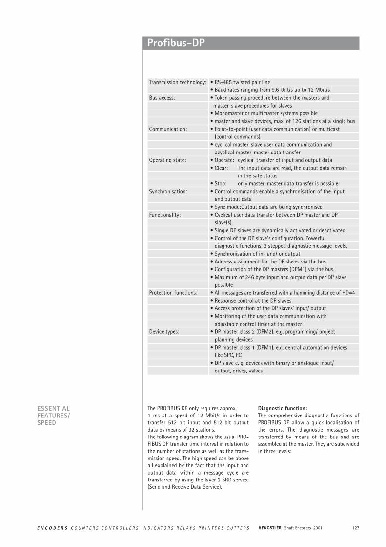
Transmission technology: • RS-485 twisted pair line• Baud rates ranging from 9.6 kbit/s up to 12 Mbit/s
Bus access: • Token passing procedure between the masters andmaster-slave procedures for slaves
• Monomaster or multimaster systems possible• master and slave devices, max. of 126 stations at a single bus
Communication: • Point-to-point (user data communication) or multicast (control commands)
• cyclical master-slave user data communication and acyclical master-master data transfer
Operating state: • Operate: cyclical transfer of input and output data• Clear: The input data are read, the output data remain
in the safe status• Stop: only master-master data transfer is possible
Synchronisation: • Control commands enable a synchronisation of the inputand output data
• Sync mode:Output data are being synchronisedFunctionality: • Cyclical user data transfer between DP master and DP
slave(s)• Single DP slaves are dynamically activated or deactivated• Control of the DP slave's configuration. Powerful
diagnostic functions, 3 stepped diagnostic message levels.• Synchronisation of in- and/ or output• Address assignment for the DP slaves via the bus• Configuration of the DP masters (DPM1) via the bus• Maximum of 246 byte input and output data per DP slave
possibleProtection functions: • All messages are transferred with a hamming distance of HD=4
• Response control at the DP slaves• Access protection of the DP slaves' input/ output• Monitoring of the user data communication with
adjustable control timer at the masterDevice types: • DP master class 2 (DPM2), e.g. programming/ project
planning devices• DP master class 1 (DPM1), e.g. central automation devices
like SPC, PC• DP slave e. g. devices with binary or analogue input/
output, drives, valves
ESSENTIALFEATURES/SPEED
The PROFIBUS DP only requires approx.1 ms at a speed of 12 Mbit/s in order totransfer 512 bit input and 512 bit outputdata by means of 32 stations. The following diagram shows the usual PRO-FIBUS DP transfer time interval in relation tothe number of stations as well as the trans-mission speed. The high speed can be aboveall explained by the fact that the input andoutput data within a message cycle aretransferred by using the layer 2 SRD service(Send and Receive Data Service).
Diagnostic function: The comprehensive diagnostic functions ofPROFIBUS DP allow a quick localisation ofthe errors. The diagnostic messages aretransferred by means of the bus and areassembled at the master. They are subdividedin three levels:
Shaft Encoders 2001128 E N C O D E R S C O U N T E R S C O N T R O L L E R S I N D I C A T O R S R E L A Y S P R I N T E R S C U T T E R S
Profibus-DP
BASIC FEATURES / SPEED
CONFIGURATION OF THESYSTEM AND DEVICE TYPES
By means of PROFIBUS DP, mono- andmulitmaster systems can be realised. For thisreason, a high level of flexibility in terms ofthe system configuration can be achieved. Amaximum of 126 devices (master or slaves)may be connected to a bus. The definitionsfor the system configuration contain thenumber of stations, the assignment of thestation address to the I/O addresses, the dataconsistency of the I/O data, the format ofthe diagnostic messages and the bus para-meters used. Each PROFIBUS DP system con-sists of different device types. There arethree device types to be distinguished:
DP master class 1 (DPM1)These devices are central control systemsexchanging information with the local stati-ons (DP slaves) during a fixed message cycle.Typical devices of this kind are stored-pro-gram controllers (SPC), PC or VME systems.
DP master class 2 (DPM2)Programming, configuration devices, andoperator panels belong to this category. Theyare used for the initial operation proceduresin order to establish the configuration of theDP system, or to operate the plants in thecourse of operation.
DP slaveA DP slave is a peripheral I/O rack (I/O, drives,HMI, valves) that reads the input informa-tion and sends output information to theperipheral equipment. Devices which provideonly input or only output information mightalso be used.The amount of input and output informationis device specific and must not exceed 246byte for the input and 246 byte for the out-put data.
Station-related diagnosisMessages on the general readiness for ser-vice of a station, like for example, overtem-perature or undervoltage.
Module-related diagnosisTheses messages indicate that a diagnosiswithin a certain I/O part (e.g. 8 bit outputmodule) of a station is in hand.
Channel related diagnosisThe error cause in relation to a single input/output bit (channel) is indicated here, likefor example, a short-circuit at output line 7.
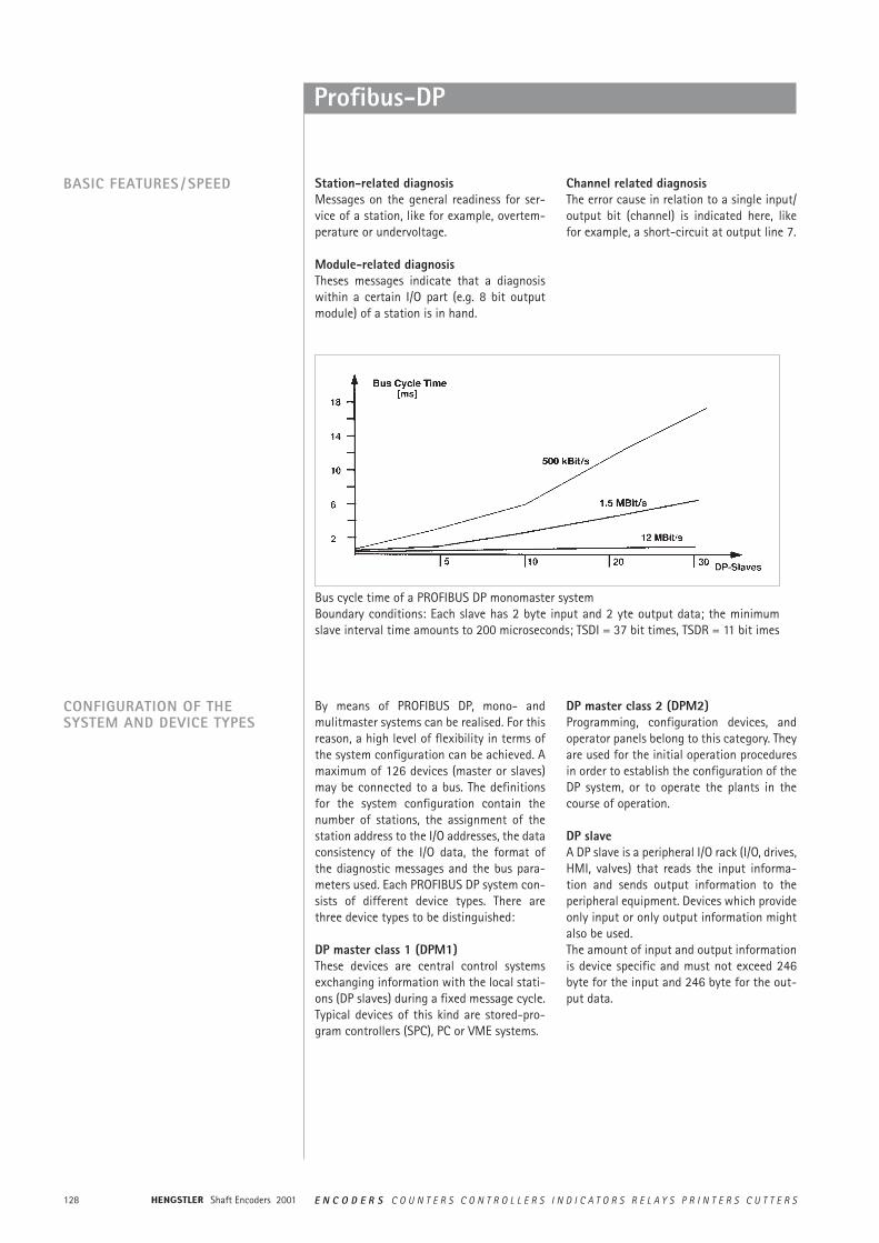
Bus cycle time of a PROFIBUS DP monomaster systemBoundary conditions: Each slave has 2 byte input and 2 yte output data; the minimumslave interval time amounts to 200 microseconds; TSDI = 37 bit times, TSDR = 11 bit imes
129E N C O D E R S C O U N T E R S C O N T R O L L E R S I N D I C A T O R S R E L A Y S P R I N T E R S C U T T E R S Shaft Encoders 2001
Profibus-DP
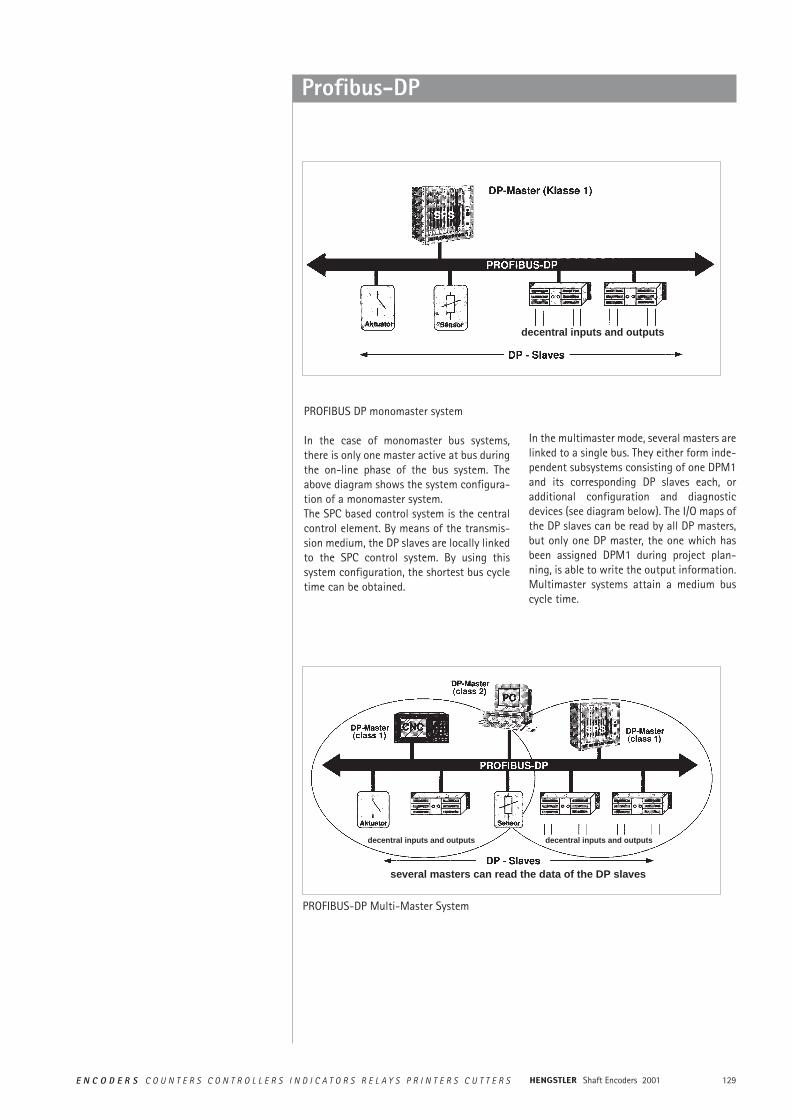
PROFIBUS DP monomaster system
In the case of monomaster bus systems,there is only one master active at bus duringthe on-line phase of the bus system. Theabove diagram shows the system configura-tion of a monomaster system. The SPC based control system is the centralcontrol element. By means of the transmis-sion medium, the DP slaves are locally linkedto the SPC control system. By using thissystem configuration, the shortest bus cycletime can be obtained.
In the multimaster mode, several masters arelinked to a single bus. They either form inde-pendent subsystems consisting of one DPM1and its corresponding DP slaves each, oradditional configuration and diagnosticdevices (see diagram below). The I/O maps ofthe DP slaves can be read by all DP masters,but only one DP master, the one which hasbeen assigned DPM1 during project plan-ning, is able to write the output information.Multimaster systems attain a medium buscycle time.
decentral inputs and outputs
PROFIBUS-DP Multi-Master System
decentral inputs and outputs decentral inputs and outputs
several masters can read the data of the DP slaves
Shaft Encoders 2001130 E N C O D E R S C O U N T E R S C O N T R O L L E R S I N D I C A T O R S R E L A Y S P R I N T E R S C U T T E R S
Profibus-DP
SYSTEM PERFORMANCE In order to obtain a high level of exchangea-bility between the devices, the system per-formance of PROFIBUS DP has also beenstandardised. It is mainly determined by theoperational status of the DPM1.
The DPM1 can either be controlled locally orvia the bus by the project planning device.The following three main states can bedistinguished:
StopThere is no data traffic between DPM1 andthe DP slaves.
ClearThe DPM1 reads the input information of theDP slaves and maintains the safe status ofthe DP slaves' output.
OperateThe DPM1 has entered the data transferphase. In case of a cyclical data traffic, theinput is read by the DP slaves while the out-put is transferred to the DP slaves.
After an error has occurred during the datatransfer phase of the DPM1, like for example,the failure of a DP slave, the response of thesystem is determined by the operating para-meter "Auto Clear".
If this parameter has been set to true, theDPM1 will set the output of all the respectiveDP slaves to the safe status, as soon as a DPslave is no longer available for user datacommunication. Afterwards, the DPM1changes to the clear status.
If this parameter is = false, the DPM1remains, even if an error occurs, in the ope-rate status, and the user can determine theresponse of the system at his own discretion.
CYCLICAL DATA TRANSFER BETWEEN DPM1 AND THE DP SLAVES
The data traffic between the DPM1 and therespective DP slaves is automatically hand-led by the DPM1 in a fixed, recurring order.When configuring the bus system, the userassigns a DP slave to the DPM1. In addition,the slaves to be included in- or excludedfrom the user data communication are defi-ned.The data traffic between the DPM1 and theDP slaves is subdivided in parametrisation,configuration, and data transfer phases.Before including a DP slave in the datatransfer phase, the DPM1 checks during the
parametrisation and configuration phase,whether the planned set configuration corre-sponds to the actual configuration of thedevice. For this check, the device type, theinformation on the format and the length aswell as the number of input and output lineshave to be correct. The user thus obtains areliable protection against parametrisationerrors. In addition to the user communica-tion, which is automatically executed by theDPM1, the user may request the new para-metrisation data to be sent to the DP slaves.
131E N C O D E R S C O U N T E R S C O N T R O L L E R S I N D I C A T O R S R E L A Y S P R I N T E R S C U T T E R S Shaft Encoders 2001
Profibus-DP
DATA TRAFFIC BETWEEN DPM1AND PROJECT PLANNINGDEVICES
Function Meaning DPM1 DPM2Get_master_Diag reads the diagnostic data of the DPM1 M O
or the collective diagnosis of the DPslaves.
Download / Upload Group reads or writes the entire configuration O O(Start_Seq, Down- / data of a DPM1 and of the respectiveUpload, End_Seq) DP slaves.Act_Para_Brct activates the bus parameters for all O O
operating DPM1 devices.Act_Param activates parameters or modifies the O O
operating status of the operatingDPM1 device.
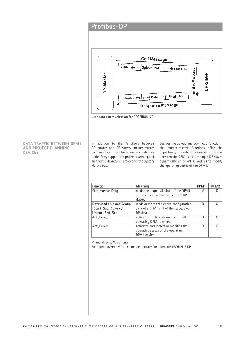
In addition to the functions between DP master and DP slaves, master-mastercommunication functions are available, seetable. They support the project planning anddiagnostic devices in projecting the systemvia the bus.
Besides the upload and download functions,the master-master functions offer theopportunity to switch the user data transferbetween the DPM1 and the single DP slavesdynamically on or off as well as to modifythe operating status of the DPM1.
User data communication for PROFIBUS-DP
M: mandatory, O: optionalFunctional overview for the master-master functions for PROFIBUS DP
Shaft Encoders 2001132 E N C O D E R S C O U N T E R S C O N T R O L L E R S I N D I C A T O R S R E L A Y S P R I N T E R S C U T T E R S
Profibus-DP
SYNC MODE In addition to the station-related user datacommunication being automatically handledby the DPM1, the masters may send controlcommands to a single slave, a group of sla-ves or all slaves at the same time. These con-trol commands are transferred as multicast.It is only by means of this multicast that thesync and freeze operating modes for theevent-controlled synchronisation of the DPslaves have been enabled.
The sync mode is started by the slaves, assoon as they receive a sync command formthe respective master. The output lines of theaddressed slaves will then be frozen in theircurrent state. The output data will be storedat the slaves during the following user datatransfers; the state of the output lines,however, will remain unchanged. Unless thenext sync command has been received, thestored output data will not be connected tothe output lines. By selecting unsync, thesync mode is terminated.
PROTECTIVE MECHANISM For reasons of safety, it is necessary to equipPROFIBUS DP with powerful protective fun-ctions against false parametrisation or fai-lure of the transmission equipment. For thispurpose, control mechanisms at the DPmaster and the DP slave have been realised,taking the form of time -out circuits. Themonitoring interval is determined duringproject planning.
At the DP masterThe DPM1 controls the data traffic of theslaves by means of the Data_Control_Timer.For each slave, a special timer is used. Thetime-out circuit will respond, if no properuser data transfer occurs during a controlinterval. In this case, the user will be informed.If the automatic response to an error(Auto_Clear = True) has been released, theDPM1 will quit the operate status, switchthe output lines of the respective slaves tothe safe status and change to the clear sta-tus.
At the DP slaveIn order to recognise errors by the master ortransmission errors, the slave executes theresponse control. If there is no data trafficduring the response control interval, theslave will automatically switch the outputlines to the safe status. When operating in multimaster systems, asupplementary access protection for the I/Olines of the slaves will be necessary. This is tomake sure that direct access can only be gai-ned by an authorised master. For all theother masters, the slaves will provide an I/Omap which can be also be read withoutaccess authorisation.
COMMUNICATION INTERFACE The communication interface correspondsto the PROFIBUS DP class 2 encoder profile.
Within this interface the class 1 functionsare included.
133E N C O D E R S C O U N T E R S C O N T R O L L E R S I N D I C A T O R S R E L A Y S P R I N T E R S C U T T E R S Shaft Encoders 2001
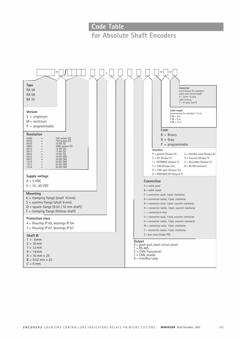
Code Table for Absolute Shaft Encoders
Resolution0360 = 360 pulses (S)0720 = 720 pulses (S)0010 = 10 Bit (S)3600 = 3600 pulses (S)0012 = 12 Bit (S)0013 = 13 Bit (S)0014 = 14 Bit (S)0412 = 16 Bit (M)0812 = 20 Bit (M)1212 = 24 Bit (M)1213 = 25 Bit (M)1214 = 26 Bit (M)
Supply voltageA = 5 VDCE = 10…30 VDC
MountingK = clamping flange (shaft 10 mm)S = synchro flange (shaft 6 mm)Q = square flange (9.52 / 10 mm shaft)F = clamping flange (Hollow shaft)
Protection class4 = Housing IP 65, bearings IP 647 = Housing IP 67, bearings IP 67
VersionS = singleturnM = multiturnP = programmable
- - -/ .
Shaft Ø1 = 6 mm 2 = 10 mm 7 = 12 mm9 = 14 mmA = 10 mm x 25 B = 9.52 mm x 25C = 8 mm
OutputK = push-pull, short circuit proofT = RS 485C = CAN-TransceiverL = CAN, doubleA = InterBus Loop
ConnectionA = cable axial
B = cable radial
C = connector axial, 12pol. clockwise
D = connector radial, 12pol. clockwise
G = connector axial, 12pol. counter clockwise
H = connector radial, 12pol. counter clockwise
I = connector2-fold
U = connector axial, 17pol. counter clockwise
V = connector radial, 17pol. counter clockwise
W = connector axial, 17pol. clockwise
Y = connector radial, 17pol. clockwise
Z = bus cover (triple PG)
InterfaceP = parallel (Output K) L = InterBus Loop (Output A)S = SSI (Output T) U = Suconet (Output T)I = INTERBUS (Output T) V = DeviceNet (Output C)C = CAN (Output CL) R = RS 485-protocolO = CAN open (Output CL)D = PROFIBUS DP (Output T)
CodeB = BinaryG = GrayP = programmable
Connector(unnecessary for standard:cable with tinned lead))C = conin 12 pole,right turningF = 37 pole, Sub-D
TypeRA 58RA 59RX 70
Cable length(unnecessary for standard: 1.5 m)D Ø = 3 mF Ø = 5 mK Ø = 10 m
Shaft Encoders 2001134 E N C O D E R S C O U N T E R S C O N T R O L L E R S I N D I C A T O R S R E L A Y S P R I N T E R S C U T T E R S
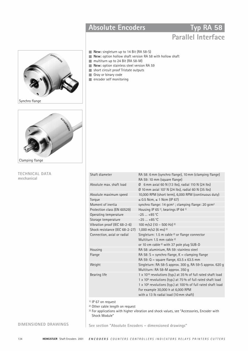
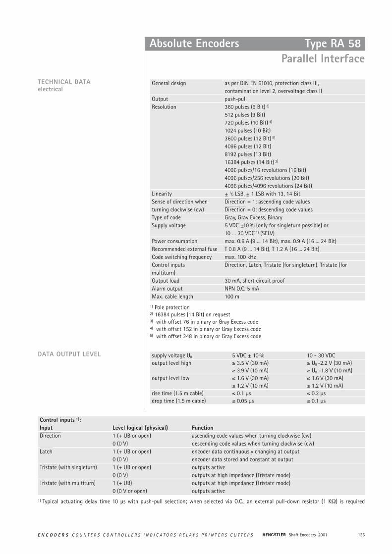
Absolute Encoders
n New: singleturn up to 14 Bit (RA 58-S)n New: option hollow shaft version RA 58 with hollow shaftn multiturn up to 24 Bit (RA 58-M)n New: option stainless steel version RA 59 n short circuit proof Tristate outputsn Gray or binary coden encoder self monitoring
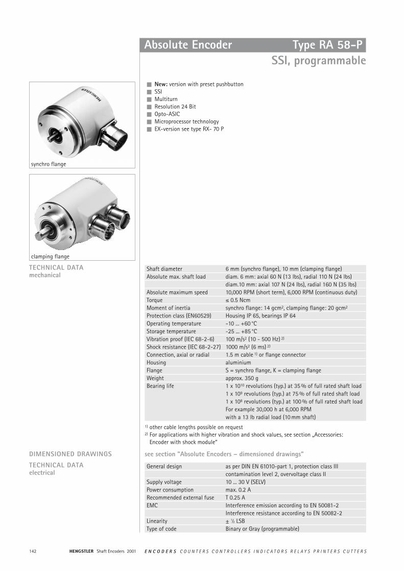
Synchro flange
Clamping flange
TECHNICAL DATAmechanical
DIMENSIONED DRAWINGS See section ”Absolute Encoders – dimensioned drawings”
Shaft diameter RA 58: 6 mm (synchro flange), 10 mm (clamping flange)RA 59: 10 mm (square flange)
Absolute max. shaft load Ø 6 mm axial 60 N (13 lbs), radial 110 N (24 lbs)Ø 10 mm axial 107 N (24 lbs), radial 60 N (35 lbs)
Absolute maximum speed 10,000 RPM (short term), 6,000 RPM (continuous duty)Torque ² 0.5 Ncm, ² 1 Ncm (IP 67)Moment of inertia synchro flange: 14 gcm2 ; clamping flange: 20 gcm2
Protection class (EN 60529) Housing IP 65 1), bearings IP 64 1)
Operating temperature -25 … +85 °CStorage temperature –25 … +85 °CVibration proof (IEC 68-2-6) 100 m/s2 (10 – 500 Hz) 3)
Shock resistance (IEC 68-2-27) 1,000 m/s2 (6 ms) 3)
Connection, axial or radial Singleturn: 1.5 m cable 2) or flange connectorMultiturn 1.5 mm cable 2)
or 10 cm cable 2) with 37 pole plug SUB-DHousing RA 58: aluminium, RA 59: stainless steelFlange RA 58: S = synchro flange, K = clamping flange
RA 59: Q = square flange, 63.5 x 63.5 mmWeight Singleturn: RA 58-S approx. 300 g, RA 59-S approx. 620 g
Multiturn: RA 58-M approx. 350 gBearing life 1 x 10¹⁰ revolutions (typ.) at 35 % of full rated shaft load
1 x 10⁹ revolutions (typ.) at 75 % of full rated shaft load1 x 108 revolutions (typ.) at 100 % of full rated shaft loadFor example 30,000 h at 6,000 RPMwith a 13 lb radial load (10 mm shaft)
1) IP 67 on request2) Other cable length on request3) For applications with higher vibration and shock values, see “Accessories, Encoder with
Shock Module“
Typ RA 58 Parallel Interface
135E N C O D E R S C O U N T E R S C O N T R O L L E R S I N D I C A T O R S R E L A Y S P R I N T E R S C U T T E R S Shaft Encoders 2001
General design as per DIN EN 61010, protection class III, contamination level 2, overvoltage class II
Output push-pullResolution 360 pulses (9 Bit) 3)
512 pulses (9 Bit)720 pulses (10 Bit) 4)
1024 pulses (10 Bit)3600 pulses (12 Bit) 5)
4096 pulses (12 Bit)8192 pulses (13 Bit)16384 pulses (14 Bit) 2)
4096 pulses/16 revolutions (16 Bit)4096 pulses/256 revolutions (20 Bit)4096 pulses/4096 revolutions (24 Bit)
Linearity ± 1⁄2 LSB, ± 1 LSB with 13, 14 BitSense of direction when Direction = 1: ascending code valuesturning clockwise (cw) Direction = 0: descending code valuesType of code Gray, Gray Excess, BinarySupply voltage 5 VDC ±10 % (only for singleturn possible) or
10 … 30 VDC 1) (SELV)Power consumption max. 0.6 A (9 ... 14 Bit), max. 0.9 A (16 ... 24 Bit)Recommended external fuse T 0.8 A (9 ... 14 Bit), T 1.2 A (16 ... 24 Bit)Code switching frequency max. 100 kHzControl inputs Direction, Latch, Tristate (for singleturn), Tristate (for multiturn)Output load 30 mA, short circuit proofAlarm output NPN O.C. 5 mAMax. cable length 100 m
Absolute Encoders
Control inputs 1):Input Level logical (physical) FunctionDirection 1 (+ UB or open) ascending code values when turning clockwise (cw)
0 (0 V) descending code values when turning clockwise (cw)Latch 1 (+ UB or open) encoder data continuously changing at output
0 (0 V) encoder data stored and constant at outputTristate (with singleturn) 1 (+ UB or open) outputs active
0 (0 V) outputs at high impedance (Tristate mode)Tristate (with multiturn) 1 (+ UB) outputs at high impedance (Tristate mode)
0 (0 V or open) outputs active
TECHNICAL DATAelectrical
supply voltage UB 5 VDC ± 10 % 10 - 30 VDCoutput level high ³ 3.5 V (30 mA) ³ UB -2.2 V (30 mA)
³ 3.9 V (10 mA) ³ UB -1.8 V (10 mA)output level low ² 1.6 V (30 mA) ² 1.6 V (30 mA)
² 1.2 V (10 mA) ² 1.2 V (10 mA)rise time (1.5 m cable) ² 0.1 µs ² 0.2 µsdrop time (1.5 m cable) ² 0.05 µs ² 0.1 µs
DATA OUTPUT LEVEL
1) Pole protection2) 16384 pulses (14 Bit) on request3) with offset 76 in binary or Gray Excess code 4) with offset 152 in binary or Gray Excess code 5) with offset 248 in binary or Gray Excess code
1) Typical actuating delay time 10 µs with push-pull selection; when selected via O.C., an external pull-down resistor (1 K½) is required
Type RA 58 Parallel Interface
Shaft Encoders 2001136 E N C O D E R S C O U N T E R S C O N T R O L L E R S I N D I C A T O R S R E L A Y S P R I N T E R S C U T T E R S
Absolute Encoders
Parallel interface with cable:Colour (PVC) 9 Bit/360 pulses 10 Bit/720 pulses 12 Bit 13 Bit 14 Bitgrey/pink N.C. N.C. N.C. N.C. SO (LSB)brown/yellow N.C. N.C. N.C. SO (LSB) S1brown/grey N.C. N.C. S0 (LSB) S1 S2red/blue N.C. N.C. S1 S2 S3violet N.C. S0 (LSB) S2 S3 S4white/brown S0 (LSB) S1 S3 S4 S5white/green S1 S2 S4 S5 S6white/yellow S2 S3 S5 S6 S7white/grey S3 S4 S6 S7 S8white/pink S4 S5 S7 S8 S9white/blue S5 S6 S8 S9 S10white/red S6 S7 S9 S10 S11white/black S7 S8 S10 S11 S12brown/green S8 (MSB) S9 (MSB) S11 (MSB) S12 (MSB) S13 (MSB)yellow Tristate S0…S8 Tristate S0…S9 Tristate S0…S11 Tristate S0...S12 Tristate S0...S13pink Latch (only binary) Latch (only binary) Latch (only binary) Latch (only binary) Latch (only binary)green Direction Direction Direction Direction Directionblack 0 V 0 V 0 V 0 V 0 Vred 5 V/10…30 VDC 5 V/10…30 VDC 5 V/10…30 VDC 5V/10...30 VDC 5 V/10...30 VDCbrown Alarm Alarm Alarm Alarm Alarm
CONNECTION DIAGRAM CABLE, SINGLETURN
Parallel interface with flange connector, 17 pole (Conin):Pin 9 Bit/360pulses 10 Bit/720 pulses 12 Bit 13 Bit 14 Bit1 S0 (LSB) S0 (LSB) S0 (LSB) S12 (MSB) S13 (MSB)2 S1 S1 S1 S11 S123 S2 S2 S2 S10 S114 S3 S3 S3 S9 S105 S4 S4 S4 S8 S96 S5 S5 S5 S7 S87 S6 S6 S6 S6 S78 S7 S7 S7 S5 S69 S8 (MSB) S8 S8 S4 S510 N.C. S9 (MSB) S9 S3 S411 N.C. N.C. S10 S2 S312 Tristate S0…S8 Tristate S0…S9 S11 (MSB) S1 S213 Latch (only binary) Latch (only binary) Latch (only binary) S0 (LSB) S114 Direction Direction Direction Direction S0 (LSB)15 0 V 0 V 0 V 0V 0 V16 5 V/10…30 VDC 5 V/10…30 VDC 5 V/10…30 VDC 5V/10...30 VDC 5/10...30VDC17 Alarm Alarm Alarm Latch/Alarm 1) Latch/Alarm 1)
CONNECTION DIAGRAM SINGLETURN, FLANGE CONNECTOR
1) Latch with binary code, Alarm wit Gray code
Type RA 58 Parallel Interface
137E N C O D E R S C O U N T E R S C O N T R O L L E R S I N D I C A T O R S R E L A Y S P R I N T E R S C U T T E R S Shaft Encoders 2001
Absolute Encoders
For mounting Ordering codeClamping eccentric 0 070 655Diaphragm coupling (hub diam. 6/6 mm) 1 076 013Diaphragm coupling (hub diam. 10/10 mm) 1 076 014
ACCESSORIES
CONNECTION DIAGRAM CABLE, MULTITURN
Parallel interfacecable (TPE) 10 cm cable with 37pole cable (TPE) 10 cm cable with 37pole
Sub-D-plug Sub-D-plugColour Pin Connection Colour Pin Connectionbrown 2 S0 white/blue 14 M41)
green 21 S1 brown/blue 33 M51)
yellow 3 S2 white/red 15 M61)
grey 22 S3 brown/red 34 M71)
pink 4 S4 white/black 16 M82)
violet 23 S5 brown/black 35 M92)
grey/pink 5 S6 grey/green 17 M102)
red/blue 24 S7 yellow/grey 36 M112)
white/green 6 S8 pink/green 18 Alarmbrown/green 25 S9 yellow/pink 10 Directionwhite/yellow 7 S10 green/blue 30 Latchyellow/brown 26 S11 yellow/blue 12 Tristatewhite/grey 8 M0 red (0.5 mm2) 13 10…30 VDCgrey/brown 27 M1 white (0.5 mm2) 31 10…30 VDCwhite/pink 9 M2 blue (0.5 mm2) 1 0 Vpink/brown 28 M3 black (0.5 mm2) 20 0 V
ORDERING DATA
KRA 5 8 – 4·/
VersionS SingleturnM Multiturn
Supply voltageA 5 VDC 6)
E 10 … 30 VDC
MountingK clamping flange
(10 mm-shaft)S synchro flange
(6 mm-shaft)Q square flange 63,5 x 63,5 3)
(6 mm-shaft)
Protection4 IP 64 3)
Shaft diam.1 6 mm (S)2 10 mm (K)
OutputK push-pull
short-circuitproof
ConnectionA cable, axialB cable radialU C 17pole axial counter clockwise 6)
V connector 17pole radial counter clockwise 6)
Wconnector 17pole axial clockwise 6)
Y connector 17pole radial clockwise 6)
P
InterfaceP parallel (output K)
CodeB BinärG Gray
Type RA 58 standardRA 59 stainless
steel 1)
Connector 4)
F 37pole Sub-D
–
1) only with mounting = Q, shaft = 2, protection = 7, connection = B2) S = singleturn, M = multiturn (4, 8 or 12 Bit revolutions)3) only for type RA 59 (stainless steel)4) optional with multiturn and connection cable: 10 cm cable with 37 pole plug Sub-D5) IP 67 on request6) only for singleturn
Resolution 2)
0360 360 Incr. (S)0009 9 Bit (S)0720 720 Incr. (S)0010 10 Bit (S)3600 3600 Incr. (S)0012 12 Bit (S)0013 13 Bit (S)0014 14 Bit (S)0412 16 Bit (M)0812 20 Bit (M)1212 24 Bit (M)
1) N. C. with resolution 16 Bit2) N. C. with resolution 16 Bit or 20 Bit
Type RA 58 Parallel Interface
Shaft Encoders 2001138 E N C O D E R S C O U N T E R S C O N T R O L L E R S I N D I C A T O R S R E L A Y S P R I N T E R S C U T T E R S
The maximum data transmission rate depends on the cable length. Please use twisted cablepairs and screened cable for clock rate / clock rate and data / data.
Absolute Encoders
n New: singleturn up to 14 Bit (RA 58-S)n New: multiturn up to 26 Bit (RA 58-M)n New: option stainless steel encoder RA 59n Gray or binary coden Programmable version or version with preset pushbutton see type RA 58-P with SSIn Ex-version see type RX 70
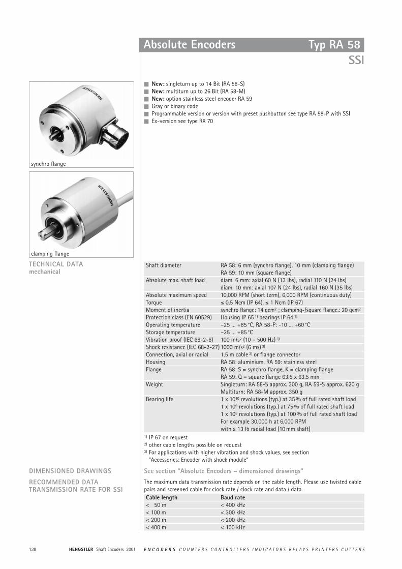
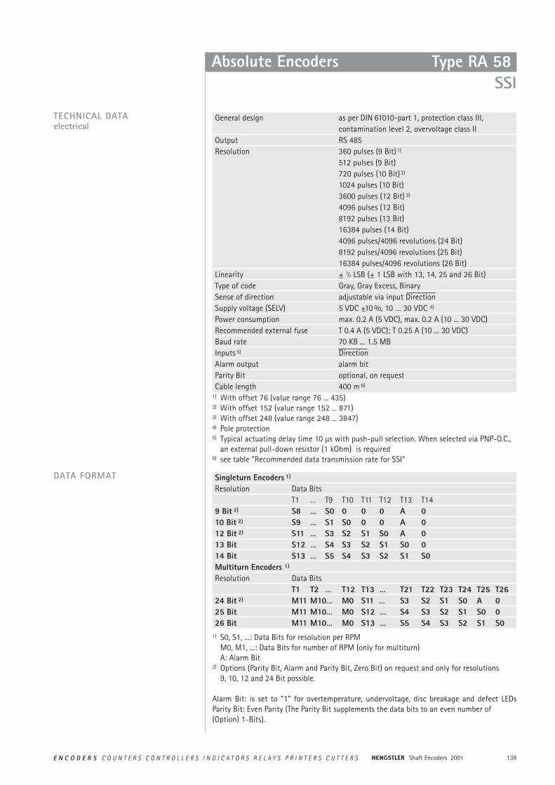
synchro flange
TECHNICAL DATAmechanical
clamping flange
Cable length Baud rate< 50 m < 400 kHz< 100 m < 300 kHz< 200 m < 200 kHz< 400 m < 100 kHz
RECOMMENDED DATA TRANSMISSION RATE FOR SSI
DIMENSIONED DRAWINGS See section ”Absolute Encoders – dimensioned drawings”
Shaft diameter RA 58: 6 mm (synchro flange), 10 mm (clamping flange)RA 59: 10 mm (square flange)
Absolute max. shaft load diam. 6 mm: axial 60 N (13 Ibs), radial 110 N (24 Ibs)diam. 10 mm: axial 107 N (24 Ibs), radial 160 N (35 Ibs)
Absolute maximum speed 10,000 RPM (short term), 6,000 RPM (continuous duty)Torque ² 0,5 Ncm (IP 64), ² 1 Ncm (IP 67)Moment of inertia synchro flange: 14 gcm2 ; clamping-/square flange.: 20 gcm2
Protection class (EN 60529) Housing IP 65 1) bearings IP 64 1)
Operating temperature –25 … +85 °C, RA 58-P: -10 … +60 °CStorage temperature –25 … +85 °CVibration proof (IEC 68-2-6) 100 m/s2 (10 – 500 Hz) 3)
Shock resistance (IEC 68-2-27) 1000 m/s2 (6 ms) 3)
Connection, axial or radial 1.5 m cable 2) or flange connectorHousing RA 58: aluminium, RA 59: stainless steelFlange RA 58: S = synchro flange, K = clamping flange
RA 59: Q = square flange 63.5 x 63.5 mmWeight Singleturn: RA 58-S approx. 300 g, RA 59-S approx. 620 g
Multiturn: RA 58-M approx. 350 gBearing life 1 x 10¹⁰ revolutions (typ.) at 35 % of full rated shaft load
1 x 10⁹ revolutions (typ.) at 75 % of full rated shaft load1 x 108 revolutions (typ.) at 100 % of full rated shaft loadFor example 30,000 h at 6,000 RPMwith a 13 lb radial load (10 mm shaft)
1) IP 67 on request2) other cable lengths possible on request3) For applications with higher vibration and shock values, see section
”Accessories: Encoder with shock module”
Typ RA 58 SSI
139E N C O D E R S C O U N T E R S C O N T R O L L E R S I N D I C A T O R S R E L A Y S P R I N T E R S C U T T E R S Shaft Encoders 2001
Absolute Encoders
General design as per DIN 61010-part 1, protection class III,contamination level 2, overvoltage class II
Output RS 485Resolution 360 pulses (9 Bit)1)
512 pulses (9 Bit)720 pulses (10 Bit) 2)
1024 pulses (10 Bit)3600 pulses (12 Bit) 3)
4096 pulses (12 Bit)8192 pulses (13 Bit)16384 pulses (14 Bit)4096 pulses/4096 revolutions (24 Bit)8192 pulses/4096 revolutions (25 Bit)16384 pulses/4096 revolutions (26 Bit)
Linearity ± 1⁄2 LSB (± 1 LSB with 13, 14, 25 and 26 Bit)Type of code Gray, Gray Excess, BinarySense of direction adjustable via input DirectionSupply voltage (SELV) 5 VDC ±10 %, 10 … 30 VDC 4)
Power consumption max. 0.2 A (5 VDC), max. 0.2 A (10 ... 30 VDC)Recommended external fuse T 0.4 A (5 VDC); T 0.25 A (10 ... 30 VDC)Baud rate 70 KB ... 1.5 MBInputs 5) DirectionAlarm output alarm bitParity Bit optional, on requestCable length 400 m 6)
TECHNICAL DATAelectrical
Singleturn Encoders 1)
Resolution Data Bits T1 … T9 T10 T11 T12 T13 T14
9 Bit 2) S8 … S0 0 0 0 A 010 Bit 2) S9 … S1 S0 0 0 A 012 Bit 2) S11 … S3 S2 S1 S0 A 013 Bit S12 … S4 S3 S2 S1 S0 014 Bit S13 … S5 S4 S3 S2 S1 S0Multiturn Encoders 1)
Resolution Data Bits T1 T2 … T12 T13 … T21 T22 T23 T24 T25 T26
24 Bit 2) M11 M10… M0 S11 … S3 S2 S1 S0 A 025 Bit M11 M10… M0 S12 … S4 S3 S2 S1 S0 026 Bit M11 M10… M0 S13 … S5 S4 S3 S2 S1 S0
DATA FORMAT
1) With offset 76 (value range 76 ... 435)2) With offset 152 (value range 152 ... 871)3) With offset 248 (value range 248 ... 3847)4) Pole protection5) Typical actuating delay time 10 µs with push-pull selection. When selected via PNP-O.C.,
an external pull-down resistor (1 kOhm) is required6) see table ”Recommended data transmission rate for SSI”
1) S0, S1, ...: Data Bits for resolution per RPMM0, M1, ...: Data Bits for number of RPM (only for multiturn)A: Alarm Bit
2) Options (Parity Bit, Alarm and Parity Bit, Zero Bit) on request and only for resolutions 9, 10, 12 and 24 Bit possible.
Alarm Bit: is set to ”1” for overtemperature, undervoltage, disc breakage and defect LEDsParity Bit: Even Parity (The Parity Bit supplements the data bits to an even number of(Option) 1-Bits).
Type RA 58 SSI
Shaft Encoders 2001140 E N C O D E R S C O U N T E R S C O N T R O L L E R S I N D I C A T O R S R E L A Y S P R I N T E R S C U T T E R S
1) Direction: + UB or not used = ascending code values for clockwise rotation cw0 V = descending code values for clockwise rotation cw
2) connected with 0V in the encoder. Please use this output to connect Direction to logically"0" if required.
Absolute Encoders
Cable Flange connector Signalbrown (0.5 mm2) 1 0 V (supply voltage)pink 2 Datayellow 3 Clock
4 N.C.blue 5 Direction1)
red 6 N.C.violet 7 N.C.white (0.5 mm2) 8 5/10 … 30 VDC
9 N.C.grey 10 Datagreen 11 Clockblack 12 0 V-signal output2)
Position indicator signo 727-SSI see section ”Accessories”For Mounting Ordering codeClamping eccentric 0 070 655Diaphragm coupling (hub diam. 6/6 mm) 1 076 013Diaphragm coupling (hub diam. 10/10 mm) 1 076 014
ACCESSORIES
Synchronous readout of the encoder data is according to the clock rate given by theSSI-counterpart.The number of clock rates is determined bythe type of encoder (singleturn resp. multi-turn) and the configuration of the specialBits as defined.For multiple transactions (the stored value isreadout several times successively) a fixedclock rate per transaction must be kept (forsingleturn 13 resp. 14 clocks, for multiturn25 resp. 26 clocks).• In the rest position, when the last clock
brush has passed by more than 30µs, thedata output is logically at ”1“.
• With the first descending clock edge theencoder data and the special bits are loa-ded in the shift register of the encoderinterface.
• With each ascending clock edge the databits are serially readout, beginning withthe MSB.
SYNCHRONOUS-SERIALTRANSFER (SSI)
• At the end of the data transfer the dataoutput is set to logically ”0“ for approx.20µs. If within these 20µs a further clock brushreaches the encoder interface, the alreadytransferred data is readout once again.This multiple transfer of the same datamakes it possible to recognize transfererrors.
• After the 20µs the data output goes to itsrest position, logically ”1“. Subsequentlynew encoder data can be readout.
CONNECTION DIAGRAM
Type RA 58 SSI
141E N C O D E R S C O U N T E R S C O N T R O L L E R S I N D I C A T O R S R E L A Y S P R I N T E R S C U T T E R S Shaft Encoders 2001
Absolute Encoders
ORDERING DATA
T– ·/Resolution 4)
0360 360 pulses (S) 0009 9 Bit (S)0720 720 pulses (S) 0010 10 Bit (S) 3600 3600 Incr. (S) 0012 12 Bit (S) 0013 13 Bit (S)0014 14 Bit (S)1212 24 Bit (M)1213 25 Bit (M)1214 26 Bit (M)
VersionS SingleturnM Multiturn
Supply voltageA 5 VDCE 10 … 30 VDC
MountingK Clamping flange
(10 mm-shaft)S Synchro flange
(6 mm-shaft)(10 mm-shaft)
Protection4 IP 64 3)
7 IP 67 2)
Shaft diam.1 6 mm (S)2 10 mm (K)
OutputT RS 485
ConnectionA cable, axialB cable, radialC flange connector 12pole axial clockwiseD flange connector 12pole radial clockwiseG flange connector 12pole axial counter clockwiseH flange connector 12pole radial counter clockwise
S
InterfaceS SSI
CodeB BinaryG Gray
1) only with mounting = Q, shaft = 2, protection = 7, connection = B2) only for type RA 59 (stainless steel)3) IP 67 on request4) S = singleturn, M = multiturn with 12 Bit revolutions
Type RA 58 StandardRA 59 Stainless
steel 1)
Type RA 58 SSI
Shaft Encoders 2001142 E N C O D E R S C O U N T E R S C O N T R O L L E R S I N D I C A T O R S R E L A Y S P R I N T E R S C U T T E R S
Absolute Encoder
n New: version with preset pushbuttonn SSIn Multiturnn Resolution 24 Bitn Opto-ASICn Microprocessor technologyn EX-version see type RX- 70 P
General design as per DIN EN 61010-part 1, protection class IIIcontamination level 2, overvoltage class II
Supply voltage 10 ... 30 V (SELV)Power consumption max. 0.2 ARecommended external fuse T 0.25 A EMC Interference emission according to EN 50081-2
Interference resistance according to EN 50082-2Linearity ± 1⁄2 LSBType of code Binary or Gray (programmable)
Shaft diameter 6 mm (synchro flange), 10 mm (clamping flange)Absolute max. shaft load diam. 6 mm: axial 60 N (13 lbs), radial 110 N (24 lbs)
diam.10 mm: axial 107 N (24 lbs), radial 160 N (35 lbs)Absolute maximum speed 10,000 RPM (short term), 6,000 RPM (continuous duty)Torque ² 0.5 NcmMoment of inertia synchro flange: 14 gcm2, clamping flange: 20 gcm2
Protection class (EN60529) Housing IP 65, bearings IP 64Operating temperature -10 ... +60 °CStorage temperature -25 ... +85 °CVibration proof (IEC 68-2-6) 100 m/s2 (10 - 500 Hz) 2)
Shock resistance (IEC 68-2-27) 1000 m/s2 (6 ms) 2)
Connection, axial or radial 1.5 m cable 1) or flange connectorHousing aluminiumFlange S = synchro flange, K = clamping flangeWeight approx. 350 gBearing life 1 x 10¹⁰ revolutions (typ.) at 35 % of full rated shaft load
1 x 10⁹ revolutions (typ.) at 75 % of full rated shaft load1 x 108 revolutions (typ.) at 100 % of full rated shaft loadFor example 30,000 h at 6,000 RPMwith a 13 lb radial load (10 mm shaft)
synchro flange
clamping flange
TECHNICAL DATAmechanical
TECHNICAL DATAelectrical
DIMENSIONED DRAWINGS see section ”Absolute Encoders – dimensioned drawings”
1) other cable lengths possible on request2) For applications with higher vibration and shock values, see section „Accessories:
Encoder with shock module“
Type RA 58-P SSI, programmable
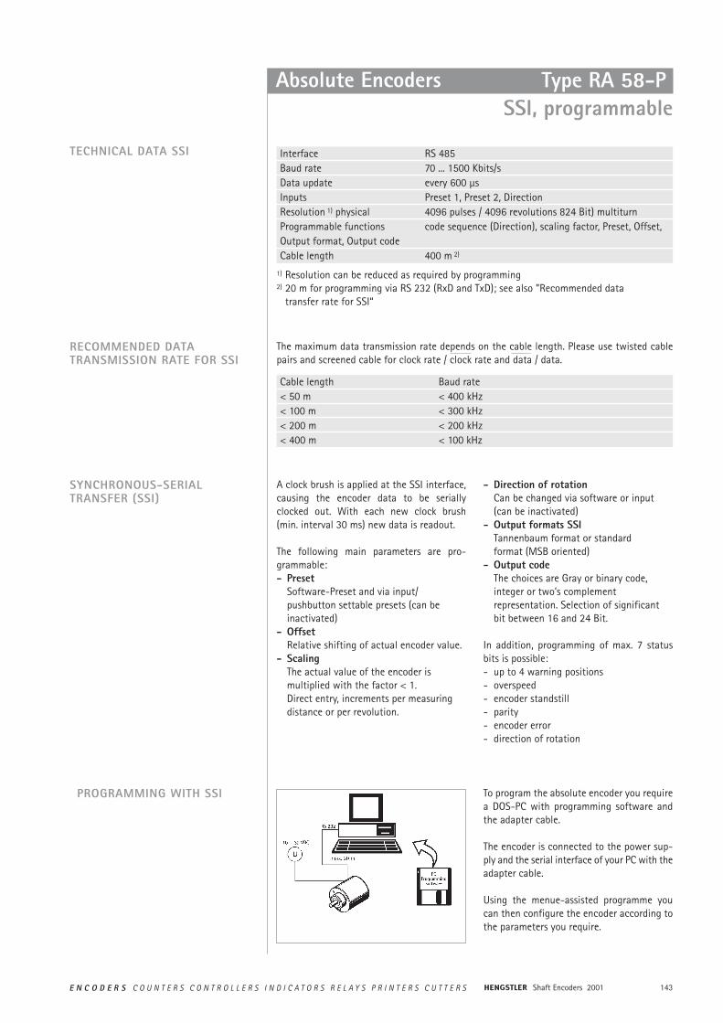
143E N C O D E R S C O U N T E R S C O N T R O L L E R S I N D I C A T O R S R E L A Y S P R I N T E R S C U T T E R S Shaft Encoders 2001
A clock brush is applied at the SSI interface,causing the encoder data to be seriallyclocked out. With each new clock brush(min. interval 30 ms) new data is readout.
The following main parameters are pro-grammable:- Preset
Software-Preset and via input/pushbutton settable presets (can beinactivated)
- OffsetRelative shifting of actual encoder value.
- ScalingThe actual value of the encoder is multiplied with the factor < 1.Direct entry, increments per measuring distance or per revolution.
- Direction of rotationCan be changed via software or input (can be inactivated)
- Output formats SSITannenbaum format or standard format (MSB oriented)
- Output codeThe choices are Gray or binary code, integer or two’s complement representation. Selection of significant bit between 16 and 24 Bit.
In addition, programming of max. 7 statusbits is possible:- up to 4 warning positions- overspeed- encoder standstill- parity- encoder error- direction of rotation
SYNCHRONOUS-SERIALTRANSFER (SSI)
PROGRAMMING WITH SSI To program the absolute encoder you requirea DOS-PC with programming software andthe adapter cable.
The encoder is connected to the power sup-ply and the serial interface of your PC with theadapter cable.
Using the menue-assisted programme youcan then configure the encoder according tothe parameters you require.
The maximum data transmission rate depends on the cable length. Please use twisted cablepairs and screened cable for clock rate / clock rate and data / data.
RECOMMENDED DATATRANSMISSION RATE FOR SSI
Interface RS 485Baud rate 70 ... 1500 Kbits/sData update every 600 µsInputs Preset 1, Preset 2, DirectionResolution 1) physical 4096 pulses / 4096 revolutions 824 Bit) multiturnProgrammable functions code sequence (Direction), scaling factor, Preset, Offset, Output format, Output codeCable length 400 m 2)
TECHNICAL DATA SSI
1) Resolution can be reduced as required by programming2) 20 m for programming via RS 232 (RxD and TxD); see also ”Recommended data
transfer rate for SSI“
Cable length Baud rate< 50 m < 400 kHz< 100 m < 300 kHz< 200 m < 200 kHz< 400 m < 100 kHz
Absolute Encoders Type RA 58-P SSI, programmable
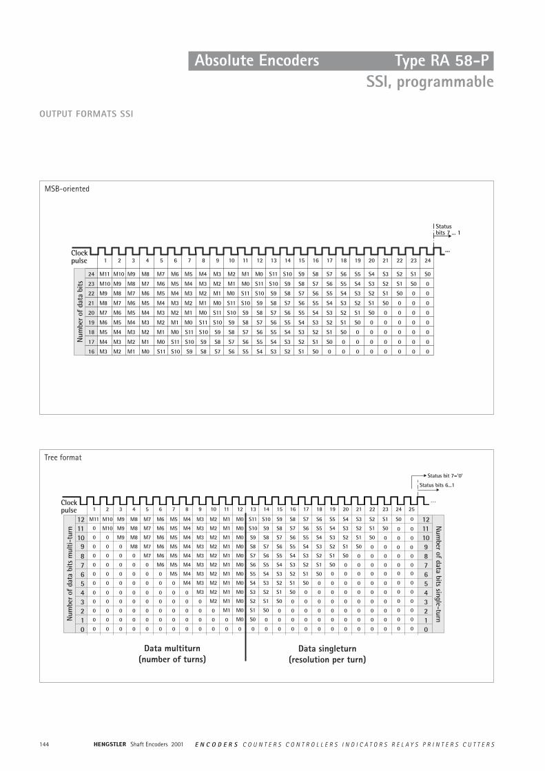
Shaft Encoders 2001144 E N C O D E R S C O U N T E R S C O N T R O L L E R S I N D I C A T O R S R E L A Y S P R I N T E R S C U T T E R S
OUTPUT FORMATS SSI
MSB-oriented
Tree format
Data singleturn(resolution per turn)
Data multiturn(number of turns)
Absolute Encoders Type RA 58-P SSI, programmable
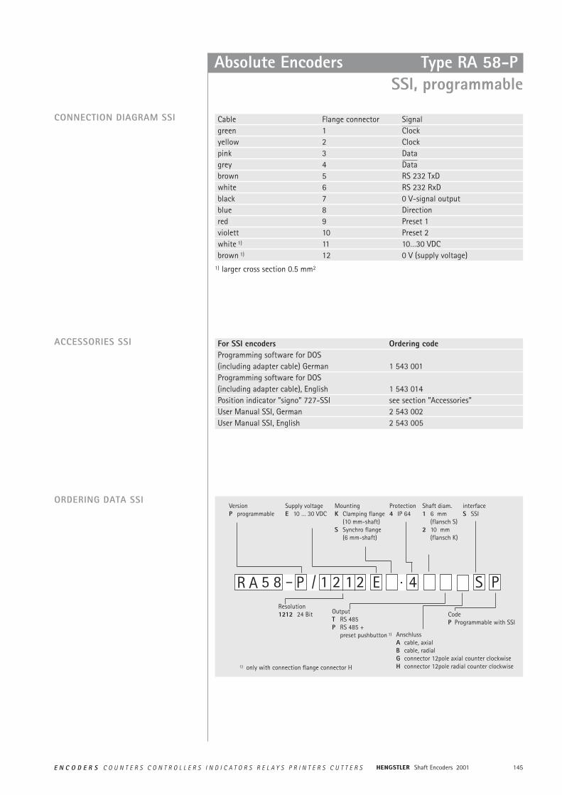
145E N C O D E R S C O U N T E R S C O N T R O L L E R S I N D I C A T O R S R E L A Y S P R I N T E R S C U T T E R S Shaft Encoders 2001
Absolute Encoders
ORDERING DATA SSI
5 8 – P 4·/Resolution1212 24 Bit
VersionP programmable
Supply voltageE 10 … 30 VDC
MountingK Clamping flange
(10 mm-shaft)S Synchro flange
(6 mm-shaft)
Protection4 IP 64
Shaft diam.1 6 mm
(flansch S)2 10 mm
(flansch K)
OutputT RS 485P RS 485 +
preset pushbutton 1) AnschlussA cable, axialB cable, radialG connector 12pole axial counter clockwiseH connector 12pole radial counter clockwise
S P
interfaceS SSI
CodeP Programmable with SSI
E1 2 1 2R A
1) only with connection flange connector H
CONNECTION DIAGRAM SSI
For SSI encoders Ordering codeProgramming software for DOS(including adapter cable) German 1 543 001Programming software for DOS(including adapter cable), English 1 543 014Position indicator ”signo” 727-SSI see section ”Accessories”User Manual SSI, German 2 543 002User Manual SSI, English 2 543 005
Cable Flange connector Signalgreen 1 Clockyellow 2 Clockpink 3 Datagrey 4 Databrown 5 RS 232 TxDwhite 6 RS 232 RxDblack 7 0 V-signal outputblue 8 Directionred 9 Preset 1violett 10 Preset 2white 1) 11 10…30 VDCbrown 1) 12 0 V (supply voltage)
ACCESSORIES SSI
1) larger cross section 0.5 mm2
Type RA 58-P SSI, programmable
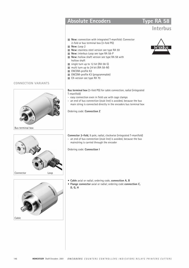
Shaft Encoders 2001146 E N C O D E R S C O U N T E R S C O N T R O L L E R S I N D I C A T O R S R E L A Y S P R I N T E R S C U T T E R S
Absolute Encoders
n New: connection with integrated T-manifold: Connector2-fold or bus terminal box (3-fold PG)
n New: Loop 2n New: stainless steel version see type RA 59 n New: interbus-Loop see type RA 58-Pn New: hollow shaft version see type RA 58 with
hollow shaftn single turn up to 12 bit (RA 58-S)n multi turn up to 24 bit (RA 58-M)n ENCOM-profile K2n ENCOM-profile K3 (programmable)n EX-version see type RX 70
CONNECTION VARIANTS
• Cable axial or radial; ordering code, connection A, B• Flange connector axial or radial; ordering code connection C,
D, G, H
Loop
Bus terminal box
Connector
Cable
Type RA 58 Interbus
Bus terminal box (3-fold PG) for cable connection, radial (integratedT-manifold)- easy connection even in field use with cage clamps- an end of bus connection (stub line) is avoided, because the bus
main string is connected directly in the encoders bus terminal box
Ordering code: Connection Z
Connector 2-fold, 9 pole, radial, clockwise (integrated T-manifold)- an end of bus connection (stub line) is avoided, because the bus
mainstring is carried through the encoder
Ordering code: Connection I
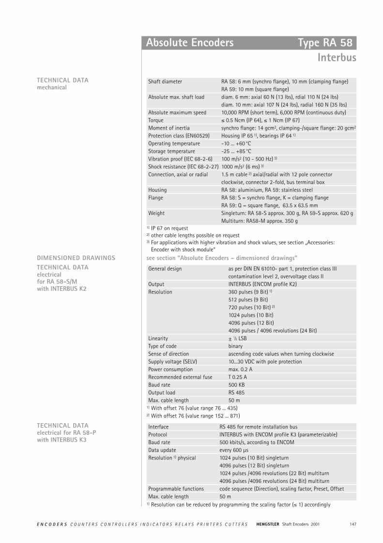
147E N C O D E R S C O U N T E R S C O N T R O L L E R S I N D I C A T O R S R E L A Y S P R I N T E R S C U T T E R S Shaft Encoders 2001
Absolute Encoders Type RA 58Interbus
General design as per DIN EN 61010- part 1, protection class IIIcontamination level 2, overvoltage class II
Output INTERBUS (ENCOM profile K2)Resolution 360 pulses (9 Bit) 1)
512 pulses (9 Bit)720 pulses (10 Bit) 2)
1024 pulses (10 Bit)4096 pulses (12 Bit)4096 pulses / 4096 revolutions (24 Bit)
Linearity ± 1⁄2 LSBType of code binarySense of direction ascending code values when turning clockwiseSupply voltage (SELV) 10...30 VDC with pole protection Power consumption max. 0.2 A Recommended external fuse T 0.25 A Baud rate 500 KBOutput load RS 485Max. cable length 50 m
TECHNICAL DATAelectricalfor RA 58-S/M with INTERBUS K2
Shaft diameter RA 58: 6 mm (synchro flange), 10 mm (clamping flange)RA 59: 10 mm (square flange)
Absolute max. shaft load diam. 6 mm: axial 60 N (13 lbs), rdial 110 N (24 lbs)diam. 10 mm: axial 107 N (24 lbs), radial 160 N (35 lbs)
Absolute maximum speed 10,000 RPM (short term), 6,000 RPM (continuous duty)Torque ² 0.5 Ncm (IP 64), ² 1 Ncm (IP 67)Moment of inertia synchro flange: 14 gcm2, clamping-/square flange: 20 gcm2
Protection class (EN60529) Housing IP 65 1), bearings IP 64 1)
Operating temperature -10 ... +60 °CStorage temperature -25 ... +85 °CVibration proof (IEC 68-2-6) 100 m/s2 (10 - 500 Hz) 3)
Shock resistance (IEC 68-2-27) 1000 m/s2 (6 ms) 3)
Connection, axial or radial 1.5 m cable 2) axial/radial with 12 pole connectorclockwise, connector 2-fold, bus terminal box
Housing RA 58: aluminium, RA 59: stainless steelFlange RA 58: S = synchro flange, K = clamping flange
RA 59: Q = square flange, 63.5 x 63.5 mmWeight Singleturn: RA 58-S approx. 300 g, RA 59-S approx. 620 g
Multiturn: RA58-M approx. 350 g
TECHNICAL DATAmechanical
DIMENSIONED DRAWINGS see section ”Absolute Encoders – dimensioned drawings”
Interface RS 485 for remote installation busProtocol INTERBUS with ENCOM profile K3 (parameterizable)Baud rate 500 kbits/s, according to ENCOMData update every 600 µsResolution 1) physical 1024 pulses (10 Bit) singleturn
4096 pulses (12 Bit) singleturn1024 pulses /4096 revolutions (22 Bit) multiturn4096 pulses /4096 revolutions (24 Bit) multiturn
Programmable functions code sequence (Direction), scaling factor, Preset, OffsetMax. cable length 50 m
TECHNICAL DATA electrical for RA 58-P with INTERBUS K3
1) IP 67 on request2) other cable lengths possible on request3) For applications with higher vibration and shock values, see section „Accessories:
Encoder with shock module“
1) With offset 76 (value range 76 ... 435)2) With offset 76 (value range 152 ... 871)
1) Resolution can be reduced by programming the scaling factor (² 1) accordingly
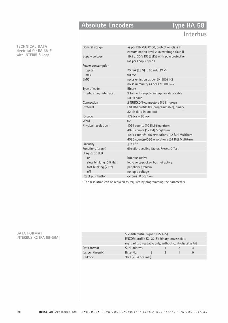
Shaft Encoders 2001148 E N C O D E R S C O U N T E R S C O N T R O L L E R S I N D I C A T O R S R E L A Y S P R I N T E R S C U T T E R S
Absolute Encoders Type RA 58 Interbus
TECHNICAL DATA electrical for RA 58-P with INTERBUS Loop
General design as per DIN VDE 0160, protection class IIIcontamination level 2, overvoltage class II
Supply voltage 19.2 ... 30 V DC (SELV) with pole protection (as per Loop 2 spec.)
Power consumptiontypical 70 mA (28 V) ... 80 mA (19 V)max 90 mA
EMC noise emission as per EN 50081-2noise immunity as per EN 50082-2
Type of code BinaryInterbus loop interface 2 fold with supply voltage via data cable
500 k baudConnection 2 QUICKON-connectors (PG11) greenProtocol ENCOM profile K3 (programmable), binary,
32 bit data in and outID code 179dez = B3hexWord 02Physical resolution 1) 1024 counts (10 Bit) Singleturn
4096 counts (12 Bit) Singleturn1024 counts/4096 revolutions (22 Bit) Multiturn4096 counts/4096 revolutions (24 Bit) Multiturn
Linearity ± 1⁄2 LSBFunctions (progr.) direction, scaling factor, Preset, OffsetDiagnostic LED
on interbus activeslow blinking (0.5 Hz) logic voltage okay, bus not activefast blinking (2 Hz) periphery problemoff no logic voltage
Reset pushbutton external 0 position
5 V differential signals (RS 485)ENCOM profile K2, 32 Bit binary process dataright adjust, readable only, without control/status bit
Data format Sµpi-address 0 1 2 3(as per Phoenix) Byte-No. 3 2 1 0ID-Code 36H (= 54 decimal)
DATA FORMATINTERBUS K2 (RA 58-S/M)
1) The resolution can be reduced as required by programming the parameters
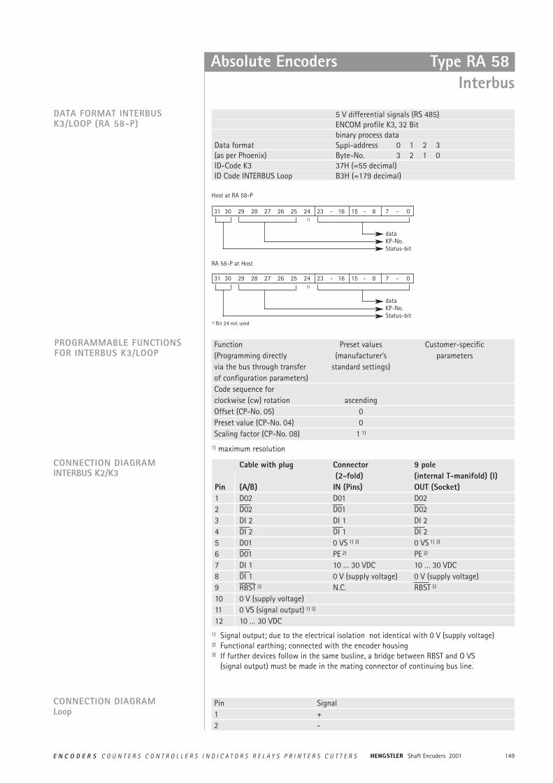
149E N C O D E R S C O U N T E R S C O N T R O L L E R S I N D I C A T O R S R E L A Y S P R I N T E R S C U T T E R S Shaft Encoders 2001
5 V differential signals (RS 485)ENCOM profile K3, 32 Bit binary process data
Data format Sµpi-address 0 1 2 3(as per Phoenix) Byte-No. 3 2 1 0ID-Code K3 37H (=55 decimal)ID Code INTERBUS Loop B3H (=179 decimal)
DATA FORMAT INTERBUSK3/LOOP (RA 58-P)
Host at RA 58-P
31 30 29 28 27 26 25 24 23 - 16 15 - 8 7 - 01)
dataKP-No.Status-bit
RA 58-P at Host
31 30 29 28 27 26 25 24 23 - 16 15 - 8 7 - 01)
dataKP-No.Status-bit
1) Bit 24 not used
Absolute Encoders Type RA 58Interbus
Function Preset values Customer-specific(Programming directly (manufacturer’s parametersvia the bus through transfer standard settings)of configuration parameters)Code sequence forclockwise (cw) rotation ascendingOffset (CP-No. 05) 0Preset value (CP-No. 04) 0Scaling factor (CP-No. 08) 1 1)
PROGRAMMABLE FUNCTIONSFOR INTERBUS K3/LOOP
Cable with plug Connector 9 pole (2-fold) (internal T-manifold) (I)
Pin (A/B) IN (Pins) OUT (Socket)1 D02 D01 D022 D02 D01 D023 DI 2 DI 1 DI 24 DI 2 DI 1 DI 25 D01 0 VS 1) 3) 0 VS 1) 3)
6 D01 PE 2) PE 2)
7 DI 1 10 … 30 VDC 10 … 30 VDC8 DI 1 0 V (supply voltage) 0 V (supply voltage)9 RBST 3) N.C. RBST 3)
10 0 V (supply voltage)11 0 VS (signal output) 1) 3)
12 10 … 30 VDC
CONNECTION DIAGRAMINTERBUS K2/K3
CONNECTION DIAGRAMLoop
Pin Signal1 +2 -
1) maximum resolution
1) Signal output; due to the electrical isolation not identical with 0 V (supply voltage)2) Functional earthing; connected with the encoder housing3) If further devices follow in the same busline, a bridge between RBST and O VS
(signal output) must be made in the mating connector of continuing bus line.
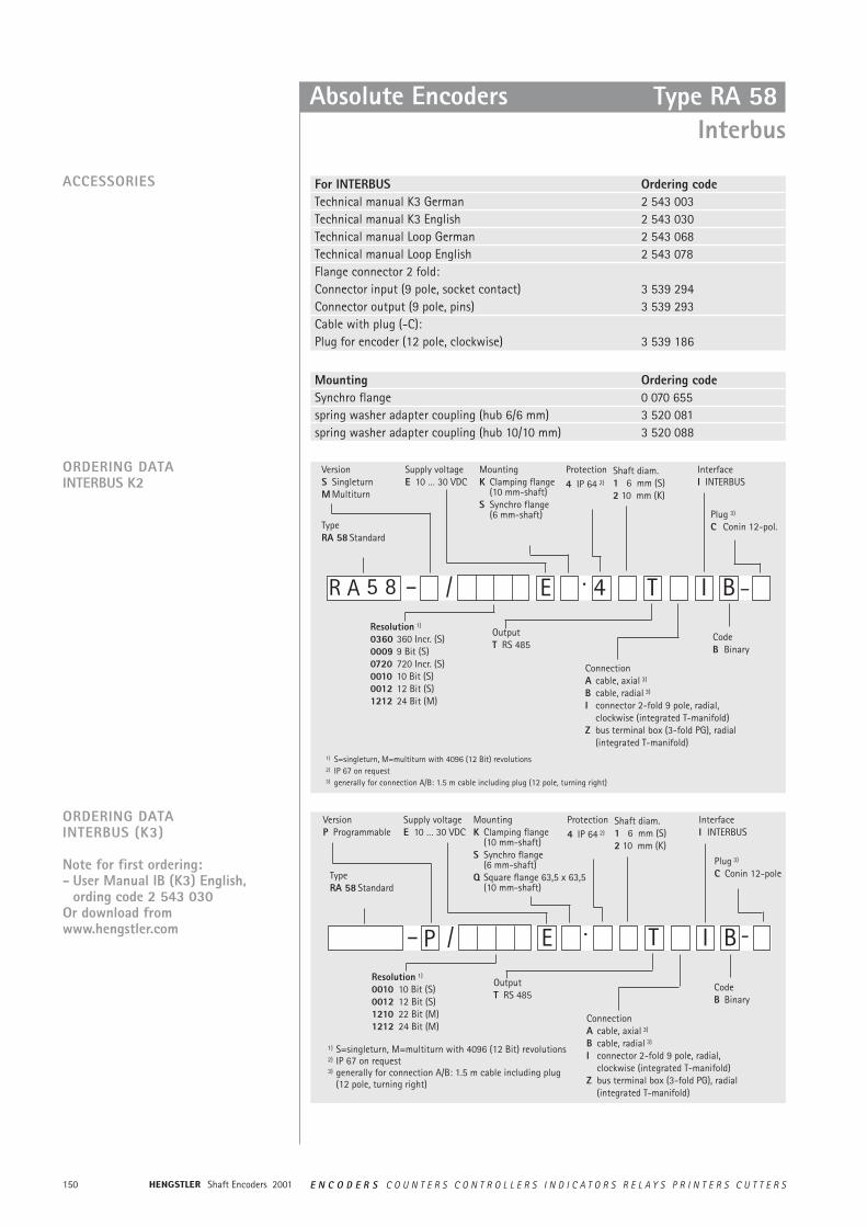
Shaft Encoders 2001150 E N C O D E R S C O U N T E R S C O N T R O L L E R S I N D I C A T O R S R E L A Y S P R I N T E R S C U T T E R S
Absolute Encoders Type RA 58 Interbus
For INTERBUS Ordering codeTechnical manual K3 German 2 543 003Technical manual K3 English 2 543 030Technical manual Loop German 2 543 068Technical manual Loop English 2 543 078Flange connector 2 fold:Connector input (9 pole, socket contact) 3 539 294Connector output (9 pole, pins) 3 539 293Cable with plug (-C):Plug for encoder (12 pole, clockwise) 3 539 186
ACCESSORIES
ORDERING DATAINTERBUS K2
5 8 – 4·/
VersionS SingleturnM Multiturn
Supply voltageE 10 … 30 VDC
MountingK Clamping flange
(10 mm-shaft)S Synchro flange
(6 mm-shaft)
Protection4 IP 64 2)
OutputT RS 485
ConnectionA cable, axial 3)
B cable, radial 3)
I connector 2-fold 9 pole, radial,clockwise (integrated T-manifold)
Z bus terminal box (3-fold PG), radial (integrated T-manifold)
I B
InterfaceI INTERBUS
CodeB Binary
E TR A
Resolution 1)
0360 360 Incr. (S)0009 9 Bit (S)0720 720 Incr. (S)0010 10 Bit (S)0012 12 Bit (S)1212 24 Bit (M)
1) S=singleturn, M=multiturn with 4096 (12 Bit) revolutions2) IP 67 on request3) generally for connection A/B: 1.5 m cable including plug (12 pole, turning right)
Type RA 58 Standard
Shaft diam.1 6 mm (S)2 10 mm (K)
Plug 3)
C Conin 12-pol.
–
ORDERING DATA INTERBUS (K3)
Note for first ordering:- User Manual IB (K3) English,
ording code 2 543 030Or download fromwww.hengstler.com – P ·/
VersionP Programmable
Supply voltageE 10 … 30 VDC
MountingK Clamping flange
(10 mm-shaft)S Synchro flange
(6 mm-shaft)Q Square flange 63,5 x 63,5
(10 mm-shaft)
Protection4 IP 64 2)
OutputT RS 485
I
InterfaceI INTERBUS
CodeB Binary
E TResolution 1)
0010 10 Bit (S)0012 12 Bit (S)1210 22 Bit (M)1212 24 Bit (M)
1) S=singleturn, M=multiturn with 4096 (12 Bit) revolutions2) IP 67 on request3) generally for connection A/B: 1.5 m cable including plug
(12 pole, turning right)
Type RA 58 Standard
Shaft diam.1 6 mm (S)2 10 mm (K)
ConnectionA cable, axial 3)
B cable, radial 3)
I connector 2-fold 9 pole, radial,clockwise (integrated T-manifold)
Z bus terminal box (3-fold PG), radial (integrated T-manifold)
Plug 3)
C Conin 12-pole
-
Mounting Ordering codeSynchro flange 0 070 655spring washer adapter coupling (hub 6/6 mm) 3 520 081spring washer adapter coupling (hub 10/10 mm) 3 520 088
B

151E N C O D E R S C O U N T E R S C O N T R O L L E R S I N D I C A T O R S R E L A Y S P R I N T E R S C U T T E R S Shaft Encoders 2001
Absolute Encoders
ORDERING DATA INTERBUS LOOP
Note for first ordering:Please include in your order:- User Manual IB Loop English,
ording code. 2 543 078Or download fromwww.hengstler.com
Type RA 58 Interbus
I– P 4·/
VersionP Programmable
Supply voltageE 10 … 30 VDC
MountingK Clamping flange
(10 mm-shaft)S Synchro flange
(6 mm-shaft)Q Square flange 63,5 x 63,5 4)
(10 mm-shaft)
Protection4 IP 64 2)
OutputA interbus Loop
L
InterfaceI INTERBUS/Loop
CodeB Binary
E AResolution 1)
0010 10 Bit (S)0012 12 Bit (S)1210 22 Bit (M)1212 24 Bit (M)
1) S=singleturn, M=multiturn with 4096 (12 Bit) revolutions2) IP 67 on request3) generally for connection A/B: 1.5 m cable including plug (12 pole, turning right)
Type RA 58 Standard
Shaft diam.1 6 mm (S)2 10 mm (K, Q)
ConnectionI Quickon
B
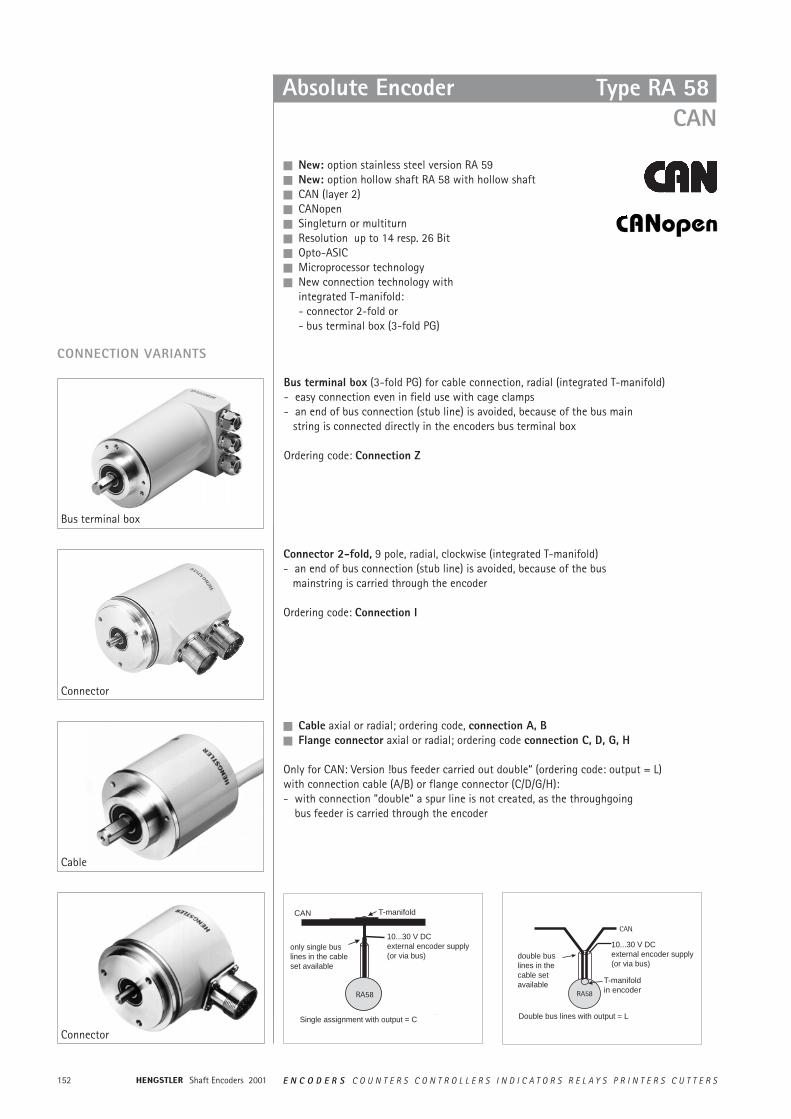
Shaft Encoders 2001152 E N C O D E R S C O U N T E R S C O N T R O L L E R S I N D I C A T O R S R E L A Y S P R I N T E R S C U T T E R S
n New: option stainless steel version RA 59n New: option hollow shaft RA 58 with hollow shaftn CAN (layer 2)n CANopenn Singleturn or multiturnn Resolution up to 14 resp. 26 Bitn Opto-ASICn Microprocessor technologyn New connection technology with
integrated T-manifold:- connector 2-fold or- bus terminal box (3-fold PG)
Absolute Encoder Type RA 58CAN
n Cable axial or radial; ordering code, connection A, Bn Flange connector axial or radial; ordering code connection C, D, G, H
Only for CAN: Version !bus feeder carried out double“ (ordering code: output = L) with connection cable (A/B) or flange connector (C/D/G/H):- with connection ”double“ a spur line is not created, as the throughgoing
bus feeder is carried through the encoder
CONNECTION VARIANTS
Bus terminal box (3-fold PG) for cable connection, radial (integrated T-manifold)- easy connection even in field use with cage clamps- an end of bus connection (stub line) is avoided, because of the bus main
string is connected directly in the encoders bus terminal box
Ordering code: Connection Z
Connector 2-fold, 9 pole, radial, clockwise (integrated T-manifold)- an end of bus connection (stub line) is avoided, because of the bus
mainstring is carried through the encoder
Ordering code: Connection I
Bus terminal box
Connector
Cable
Connector
CAN
only single buslines in the cableset available
10...30 V DCexternal encoder supply(or via bus)
Single assignment with output = C
10...30 V DCexternal encoder supply(or via bus)
Double bus lines with output = L
T-manifold
T-manifoldin encoder
double buslines in thecable set available
153E N C O D E R S C O U N T E R S C O N T R O L L E R S I N D I C A T O R S R E L A Y S P R I N T E R S C U T T E R S Shaft Encoders 2001
Absolute Encoders Type RA 58CAN
TECHNICAL DATAmechanical
Shaft diameter RA 58: 6 mm (synchro flange), 10 mm (clamping flange)RA 59: 10 mm (square flange)
Absolute max. shaft load diam. 6 mm: axial 60 N (13 lbs), rdial 110 N (24 lbs)diam. 10 mm: axial 107 N (24 lbs), radial 160 N (35 lbs)
Absolute maximum speed 10,000 RPM (short term), 6,000 RPM (continuous duty)Torque £ 0.5 Ncm (IP 65), £ 1 Ncm (IP 67)Moment of inertia synchro flange: 14 gcm2, clamping-/square flange: 20 gcm2
Protection class (EN60529) Housing IP 65 1) bearings IP 64 1)
Operating temperature -25 ... +85 °C (CAN, Profibus DP)-10 ... +60 °C (InterBus)
Storage temperature -25 ... +85 °CVibration proof (IEC 68-2-6) 100 m/s2 (10 - 500 Hz) 2)
Shock resistance (IEC 68-2-27) 1000 m/s2 (6 ms) 2)
Connection see connection variantsHousing RA 58: aluminium, RA 59: stainless steelFlange RA 58: S = synchro flange, K = clamping flange
RA 59: Q = square flange, 63.5 x 63.5 mmWeight Singleturn: RA 58-S approx. 300 g, RA 59-S approx. 620 g
Multiturn: RA58-M approx. 350 gBearing life 1 x 10¹⁰ revolutions (typ.) at 35 % of full rated shaft load
1 x 10⁹ revolutions (typ.) at 75 % of full rated shaft load1 x 108 revolutions (typ.) at 100 % of full rated shaft loadFor example 30,000 h at 6,000 RPMwith a 13 lb radial load (10 mm shaft)
DIMENSIONED DRAWINGS see section ”Absolute Encoders – dimensioned drawings”
1) for singleturn IP 67 is also available on request2) For applications with higher vibration and shock values, see section ”Accessories:
Encoder with shock module“
Shaft Encoders 2001154 E N C O D E R S C O U N T E R S C O N T R O L L E R S I N D I C A T O R S R E L A Y S P R I N T E R S C U T T E R S
General design as per DIN EN 61010- part 1, protection class IIIcontamination level 2, overvoltage class II
Supply voltage 10 ... 30 V DC (SELV)Power consumption max. 0.23 A Recommended external fuse T 0.25 A EMC Interference emission according to EN 50081-2
Interference resistance accordng to EN 50082-2Linearity ± 1⁄2 LSB (± 1 LSB with resolution 13, 14, 25, 26 Bit)Type of code Binary; with SSI: Binary and Gray (programmable)Interface CAN High Speed according to ISO / DIS 11898, basic and
full CAN, CAN specifications 2.0 B (11 and 29 Bit identifer)Protocol layer 2 or CANopen according to profile DSP 406 with
additional functionsBaud rate settable with DIP switches from 10 to 1000 Kbits/sBase identifier/ settable with DIP switchesNode numberResolution 1) physical 360 pulses (9 Bit) singleturn (only for CAN layer 2)
512 pulses (9 Bit) singleturn (only for CAN layer 2)720 pulses (10 Bit) singleturn (only for CAN layer 2)1024 pulses (10 Bit) singleturn4096 pulses (12 Bit) singleturn8192 pulses (13 Bit) singleturn16384 pulses (14 Bit) singleturn4096 pulses / 4096 revolutions (24 Bit) multiturn8192 pulses / 4096 revolutions (25 Bit) multiturn16384 pulses / 4096 revolutions (26 Bit) multiturn
Programmable functions CANopen:poll mode or auto mode with adjustable cycle time, codesequence (Direction) resolution per revolution, total resolution, Preset, Offset, up to 4 warning positions, additional output of speed / accelerationCAN shift 2:poll mode or auto mode with adjustable cycle time, codesequence (Direction), up to 4 warning positions
TECHNICAL DATAelectrical
1) with CANopen the resolution can be reduced as required by programming the parameters
Absolute Encoders Type RA 58CAN
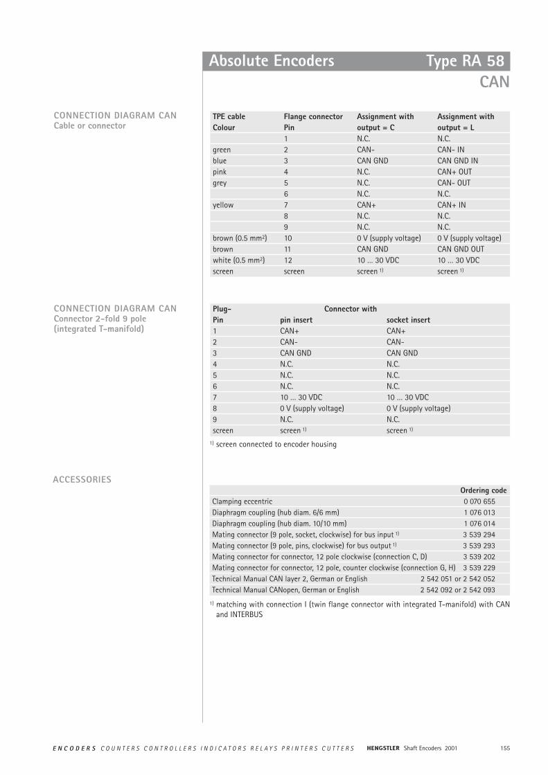
155E N C O D E R S C O U N T E R S C O N T R O L L E R S I N D I C A T O R S R E L A Y S P R I N T E R S C U T T E R S Shaft Encoders 2001
TPE cable Flange connector Assignment with Assignment with Colour Pin output = C output = L
1 N.C. N.C.green 2 CAN- CAN- INblue 3 CAN GND CAN GND INpink 4 N.C. CAN+ OUTgrey 5 N.C. CAN- OUT
6 N.C. N.C.yellow 7 CAN+ CAN+ IN
8 N.C. N.C.9 N.C. N.C.
brown (0.5 mm2) 10 0 V (supply voltage) 0 V (supply voltage)brown 11 CAN GND CAN GND OUTwhite (0.5 mm2) 12 10 … 30 VDC 10 … 30 VDCscreen screen screen 1) screen 1)
CONNECTION DIAGRAM CANCable or connector
CONNECTION DIAGRAM CANConnector 2-fold 9 pole(integrated T-manifold)
Plug- Connector withPin pin insert socket insert1 CAN+ CAN+2 CAN- CAN-3 CAN GND CAN GND4 N.C. N.C.5 N.C. N.C.6 N.C. N.C.7 10 … 30 VDC 10 … 30 VDC8 0 V (supply voltage) 0 V (supply voltage)9 N.C. N.C.screen screen 1) screen 1)
Absolute Encoders Type RA 58 CAN
ACCESSORIES
1) screen connected to encoder housing
Ordering codeClamping eccentric 0 070 655Diaphragm coupling (hub diam. 6/6 mm) 1 076 013Diaphragm coupling (hub diam. 10/10 mm) 1 076 014Mating connector (9 pole, socket, clockwise) for bus input 1) 3 539 294Mating connector (9 pole, pins, clockwise) for bus output 1) 3 539 293Mating connector for connector, 12 pole clockwise (connection C, D) 3 539 202Mating connector for connector, 12 pole, counter clockwise (connection G, H) 3 539 229Technical Manual CAN layer 2, German or English 2 542 051 or 2 542 052Technical Manual CANopen, German or English 2 542 092 or 2 542 093
1) matching with connection I (twin flange connector with integrated T-manifold) with CANand INTERBUS
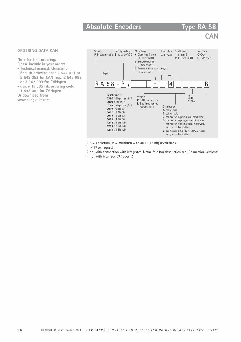
Shaft Encoders 2001156 E N C O D E R S C O U N T E R S C O N T R O L L E R S I N D I C A T O R S R E L A Y S P R I N T E R S C U T T E R S
Absolute Encoders
ORDERING DATA CAN
Note for first ordering:Please include in your order:- Technical manual, German or
English ordering code 2 542 051 or2 542 052 for CAN resp. 2 542 092or 2 542 093 for CANopen
- disc with EDS file ordering code1 543 061 for CANopen
Or download fromwww.hengstler.com
1) S = singleturn, M = multiturn with 4096 (12 Bit) revolutions2) IP 67 on request3) not with connection with integrated T-manifold (for description see „Connection versions“4) not with interface CANopen (0)
5 8 – P 4·/
VersionP Programmable
Supply voltageE 10 … 30 VDC
MountingK Clamping flange
(10 mm-shaft)S Synchro flange
(6 mm-shaft)S Square flange 63,5 x 63,5 4)
(6 mm-shaft)
Protection4 IP 64 2)
Shaft diam.1 6 mm (S)2 10 mm (K, Q)
OutputC CAN TransceiverL Bus lines carried
out double 3) ConnectionA cable, axialB cable, radialC connector 12pole, axial, clockwiseD connector 12pole, radial, clockwiseI connector 2-fach, 9pole, clockwise,
integrated T-manifoldZ bus terminal box (3-fold PG), radial,
integrated T-manifold
B
InterfaceC CANO CANopen
CodeB Binary
ER A
Resolution 1)
0360 360 pulses (S) 4)
0009 9 Bit (S) 4)
0720 720 pulses (S) 4)
0010 10 Bit (S)0012 12 Bit (S)0013 13 Bit (S)0014 14 Bit (S)1212 24 Bit (M)1213 25 Bit (M)1214 26 Bit (M)
Type
Type RA 58 CAN
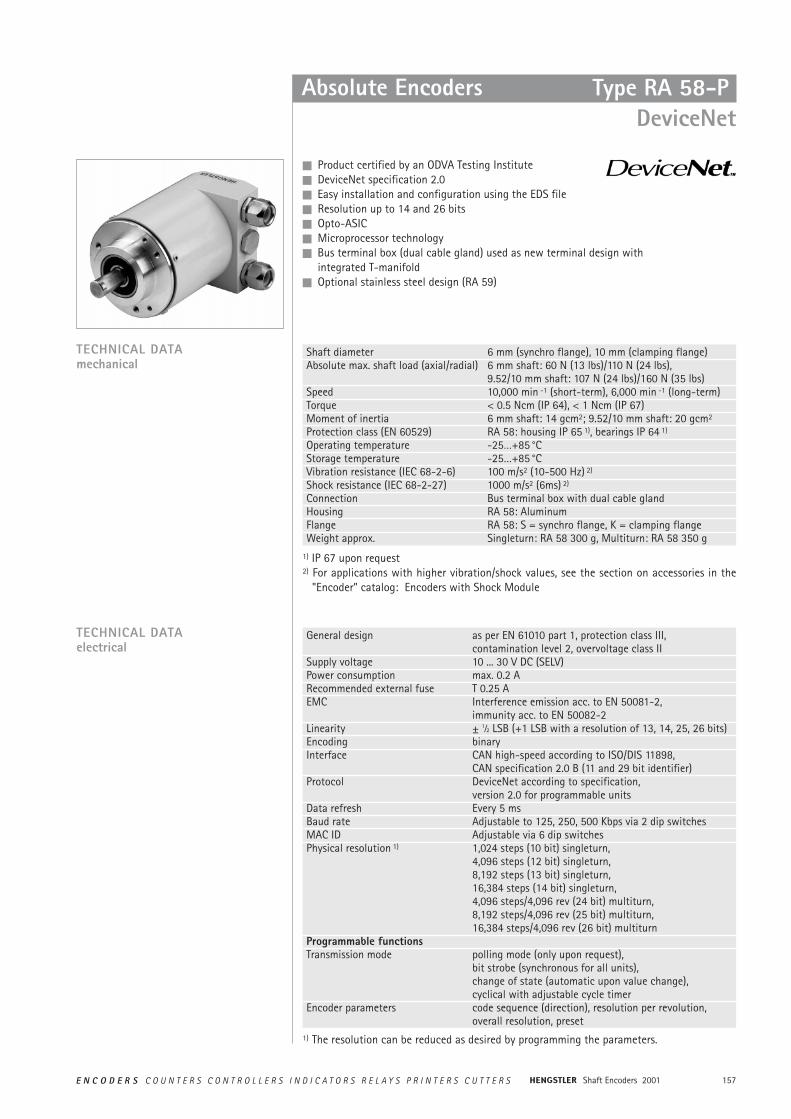
157E N C O D E R S C O U N T E R S C O N T R O L L E R S I N D I C A T O R S R E L A Y S P R I N T E R S C U T T E R S Shaft Encoders 2001
Absolute Encoders Type RA 58-P DeviceNet
n Product certified by an ODVA Testing Instituten DeviceNet specification 2.0n Easy installation and configuration using the EDS filen Resolution up to 14 and 26 bitsn Opto-ASICn Microprocessor technologyn Bus terminal box (dual cable gland) used as new terminal design with
integrated T-manifoldn Optional stainless steel design (RA 59)
Shaft diameter 6 mm (synchro flange), 10 mm (clamping flange)Absolute max. shaft load (axial/radial) 6 mm shaft: 60 N (13 lbs)/110 N (24 lbs),
9.52/10 mm shaft: 107 N (24 lbs)/160 N (35 lbs)Speed 10,000 min -1 (short-term), 6,000 min -1 (long-term)Torque < 0.5 Ncm (IP 64), < 1 Ncm (IP 67)Moment of inertia 6 mm shaft: 14 gcm2; 9.52/10 mm shaft: 20 gcm2
Protection class (EN 60529) RA 58: housing IP 65 1), bearings IP 64 1)
Operating temperature -25…+85 °CStorage temperature -25…+85 °C Vibration resistance (IEC 68-2-6) 100 m/s2 (10-500 Hz) 2)
Shock resistance (IEC 68-2-27) 1000 m/s2 (6ms) 2)
Connection Bus terminal box with dual cable glandHousing RA 58: AluminumFlange RA 58: S = synchro flange, K = clamping flangeWeight approx. Singleturn: RA 58 300 g, Multiturn: RA 58 350 g
General design as per EN 61010 part 1, protection class III, contamination level 2, overvoltage class II
Supply voltage 10 ... 30 V DC (SELV)Power consumption max. 0.2 ARecommended external fuse T 0.25 AEMC Interference emission acc. to EN 50081-2,
immunity acc. to EN 50082-2Linearity ± 1⁄2 LSB (+1 LSB with a resolution of 13, 14, 25, 26 bits)Encoding binaryInterface CAN high-speed according to ISO/DIS 11898,
CAN specification 2.0 B (11 and 29 bit identifier)Protocol DeviceNet according to specification,
version 2.0 for programmable unitsData refresh Every 5 msBaud rate Adjustable to 125, 250, 500 Kbps via 2 dip switchesMAC ID Adjustable via 6 dip switchesPhysical resolution 1) 1,024 steps (10 bit) singleturn,
4,096 steps (12 bit) singleturn, 8,192 steps (13 bit) singleturn, 16,384 steps (14 bit) singleturn, 4,096 steps/4,096 rev (24 bit) multiturn, 8,192 steps/4,096 rev (25 bit) multiturn, 16,384 steps/4,096 rev (26 bit) multiturn
Programmable functionsTransmission mode polling mode (only upon request),
bit strobe (synchronous for all units), change of state (automatic upon value change), cyclical with adjustable cycle timer
Encoder parameters code sequence (direction), resolution per revolution, overall resolution, preset
TECHNICAL DATAelectrical
1) The resolution can be reduced as desired by programming the parameters.
TECHNICAL DATAmechanical
1) IP 67 upon request2) For applications with higher vibration/shock values, see the section on accessories in the
"Encoder” catalog: Encoders with Shock Module
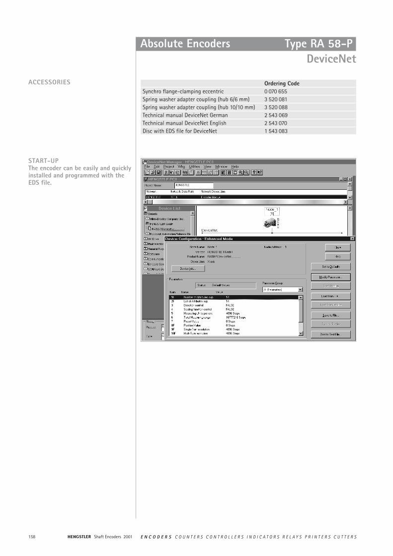
Shaft Encoders 2001158 E N C O D E R S C O U N T E R S C O N T R O L L E R S I N D I C A T O R S R E L A Y S P R I N T E R S C U T T E R S
Absolute Encoders Type RA 58-PDeviceNet
Ordering CodeSynchro flange-clamping eccentric 0 070 655Spring washer adapter coupling (hub 6/6 mm) 3 520 081Spring washer adapter coupling (hub 10/10 mm) 3 520 088Technical manual DeviceNet German 2 543 069Technical manual DeviceNet English 2 543 070Disc with EDS file for DeviceNet 1 543 083
START-UPThe encoder can be easily and quicklyinstalled and programmed with theEDS file.
ACCESSORIES
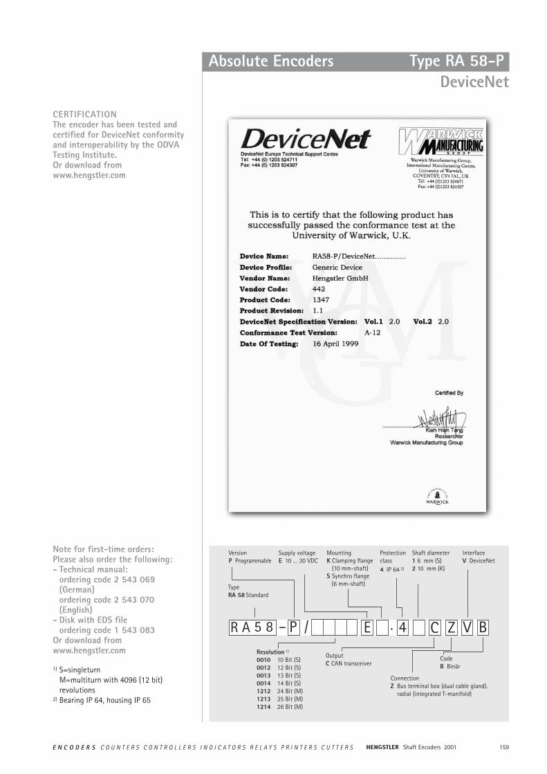
159E N C O D E R S C O U N T E R S C O N T R O L L E R S I N D I C A T O R S R E L A Y S P R I N T E R S C U T T E R S Shaft Encoders 2001
Absolute Encoders Type RA 58-PDeviceNet
CERTIFICATIONThe encoder has been tested and certified for DeviceNet conformityand interoperability by the ODVATesting Institute.Or download fromwww.hengstler.com
Note for first-time orders:Please also order the following:- Technical manual:
ordering code 2 543 069(German) ordering code 2 543 070(English)
- Disk with EDS fileordering code 1 543 083
Or download fromwww.hengstler.com
Z5 8 – P 4./
VersionP Programmable
Supply voltageE 10 … 30 VDC
MountingK Clamping flange
(10 mm-shaft)S Synchro flange
(6 mm-shaft)
Protectionclass4 IP 64 2)
Shaft diameter1 6 mm (S)2 10 mm (K)
OutputC CAN transceiver
ConnectionZ Bus terminal box (dual cable gland).
radial (integrated T-manifold)
V B
InterfaceV DeviceNet
CodeB Binär
E CR A
Resolution 1)
0010 10 Bit (S)0012 12 Bit (S)0013 13 Bit (S)0014 14 Bit (S)1212 24 Bit (M)1213 25 Bit (M)1214 26 Bit (M)
1) S=singleturnM=multiturn with 4096 (12 bit) revolutions
2) Bearing IP 64, housing IP 65
Type RA 58 Standard
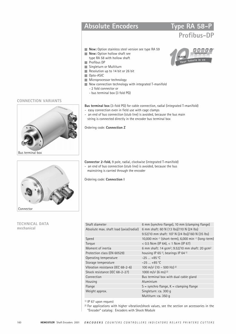
Shaft Encoders 2001160 E N C O D E R S C O U N T E R S C O N T R O L L E R S I N D I C A T O R S R E L A Y S P R I N T E R S C U T T E R S
n New: Option stainless steel version see type RA 59n New: Option hollow shaft see
type RA 58 with hollow shaftn Profibus DPn Singleturn or Multiturnn Resolution up to 14 bit or 26 bitn Opto-ASICn Microprocessor technologyn New connection technology with integrated T-manifold
- 2 fold connector or- bus terminal box (3 fold PG)
Absolute Encoders Type RA 58-PProfibus-DP
CONNECTION VARIANTSBus terminal box (3-fold PG) for cable connection, radial (integrated T-manifold)- easy connection even in field use with cage clamps- an end of bus connection (stub line) is avoided, because the bus main
string is connected directly in the encoder bus terminal box
Ordering code: Connection Z
Connector 2-fold, 9 pole, radial, clockwise (integrated T-manifold)- an end of bus connection (stub line) is avoided, because the bus
mainstring is carried through the encoder
Ordering code: Connection I
TECHNICAL DATAmechanical
Shaft diameter 6 mm (synchro flange), 10 mm (clamping flange)Absolute max. shaft load (axial/radial) 6 mm shaft: 60 N (13 lbs)/110 N (24 lbs)
9.52/10 mm shaft: 107 N (24 lbs)/160 N (35 lbs)Speed 10,000 min -1 (short-term), 6,000 min -1 (long-term)Torque < 0.5 Ncm (IP 64), < 1 Ncm (IP 67)Moment of inertia 6 mm shaft: 14 gcm2; 9.52/10 mm shaft: 20 gcm2
Protection class (EN 60529) housing IP 65 1), bearings IP 64 1)
Operating temperature -25 … +85 °C Storage temperature –25 … +85 °CVibration resistance (IEC 68-2-6) 100 m/s2 (10 – 500 Hz) 2)
Shock resistance (IEC 68-2-27) 1000 m/s2 (6 ms) 2)
Connection Bus terminal box with dual cable glandHousing AluminiumFlange S = synchro flange, K = clamping flangeWeight approx. Singleturn: ca. 300 g
Multiturn: ca. 350 g1) IP 67 upon request2) For applications with higher vibration/shock values, see the section on accessories in the
"Encoder” catalog: Encoders with Shock Module
Bus terminal box
Connector
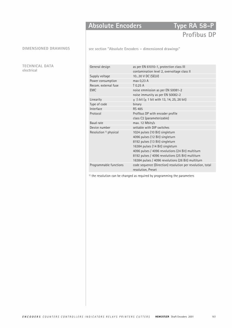
161E N C O D E R S C O U N T E R S C O N T R O L L E R S I N D I C A T O R S R E L A Y S P R I N T E R S C U T T E R S Shaft Encoders 2001
General design as per EN 61010-1, protection class IIIcontamination level 2, overvoltage class II
Supply voltage 10...30 V DC (SELV)Power consumption max 0,23 ARecom. external fuse T 0.25 AEMC noise emmission as per EN 50081-2
noise immunity as per EN 50082-2Linearity ± 1/2 bit (± 1 bit with 13, 14, 25, 26 bit)Type of code binaryInterface RS 485Protocol Profibus DP with encoder profile
class C2 (parameterizable)Baud rate max. 12 Mbits/sDevice number settable with DIP switchesResolution 1) physical 1024 pulses (10 Bit) singleturn
4096 pulses (12 Bit) singleturn8192 pulses (13 Bit) singleturn16384 pulses (14 Bit) singleturn4096 pulses / 4096 revolutions (24 Bit) multiturn8192 pulses / 4096 revolutions (25 Bit) multiturn16384 pulses / 4096 revolutions (26 Bit) multiturn
Programmable functions code sequence (Direction) resolution per revolution, totalresolution, Preset
TECHNICAL DATAelectrical
DIMENSIONED DRAWINGS see section ”Absolute Encoders – dimensioned drawings”
Absolute Encoders Type RA 58-PProfibus DP
1) the resolution can be changed as required by programming the parameters
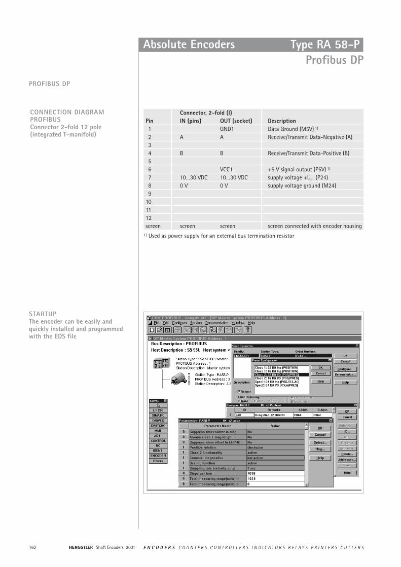
Shaft Encoders 2001162 E N C O D E R S C O U N T E R S C O N T R O L L E R S I N D I C A T O R S R E L A Y S P R I N T E R S C U T T E R S
Absolute Encoders Type RA 58-PProfibus DP
PROFIBUS DP
CONNECTION DIAGRAM PROFIBUSConnector 2-fold 12 pole(integrated T-manifold)
Connector, 2-fold (I)Pin IN (pins) OUT (socket) Description1 GND1 Data Ground (M5V) 1)
2 A A Receive/Transmit Data-Negative (A)34 B B Receive/Transmit Data-Positive (B)56 VCC1 +5 V signal output (P5V) 1)
7 10…30 VDC 10…30 VDC supply voltage +UB (P24)8 0 V 0 V supply voltage ground (M24)9
101112screen screen screen screen connected with encoder housing
STARTUPThe encoder can be easily and quickly installed and programmedwith the EDS file
1) Used as power supply for an external bus termination resistor
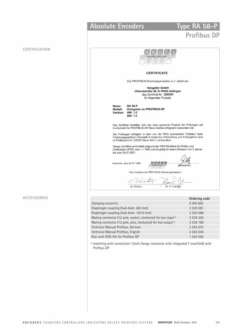
163E N C O D E R S C O U N T E R S C O N T R O L L E R S I N D I C A T O R S R E L A Y S P R I N T E R S C U T T E R S Shaft Encoders 2001
Absolute Encoders Type RA 58-PProfibus DP
CERTIFICATION
ACCESSORIES Ordering codeClamping eccentric 0 070 655Diaphragm coupling (hub diam. 6/6 mm) 3 520 081Diaphragm coupling (hub diam. 10/10 mm) 3 520 088Mating connector (12 pole, socket, clockwise) for bus input1) 3 539 202Mating connector (12 pole, pins, clockwise) for bus output1) 3 539 186Technical Manual Profibus, German 2 543 037 Technical Manual Profibus, English 2 543 045Disc with GSD-file for Profibus DP 1 543 062
1) matching with connection I (twin flange connector with integrated T-manifold) withProfibus DP
CERTIFICATE
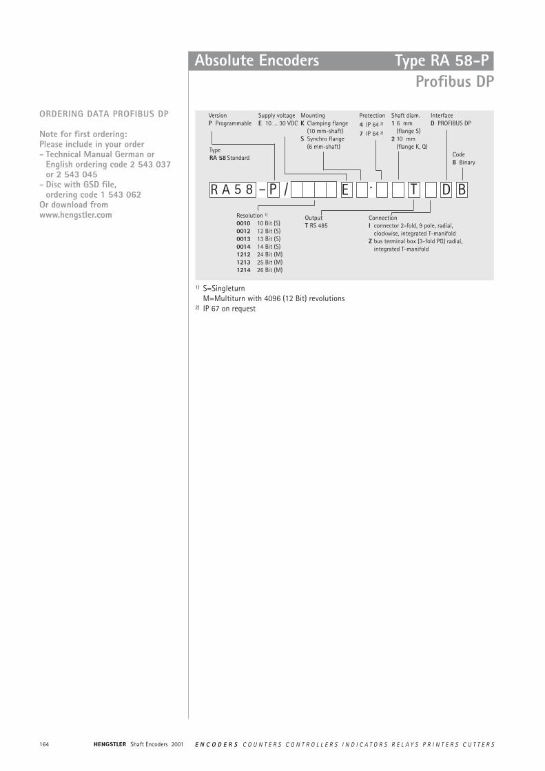
Shaft Encoders 2001164 E N C O D E R S C O U N T E R S C O N T R O L L E R S I N D I C A T O R S R E L A Y S P R I N T E R S C U T T E R S
ORDERING DATA PROFIBUS DP
Note for first ordering:Please include in your order- Technical Manual German or
English ordering code 2 543 037 or 2 543 045
- Disc with GSD file, ordering code 1 543 062
Or download fromwww.hengstler.com
1) S=SingleturnM=Multiturn with 4096 (12 Bit) revolutions
2) IP 67 on request
5 8 – P ·/
VersionP Programmable
Supply voltageE 10 … 30 VDC
MountingK Clamping flange
(10 mm-shaft)S Synchro flange
(6 mm-shaft)
Protection4 IP 64 2)
7 IP 64 2)
Shaft diam.1 6 mm
(flange S)2 10 mm
(flange K, Q)
OutputT RS 485
ConnectionI connector 2-fold, 9 pole, radial,
clockwise, integrated T-manifoldZ bus terminal box (3-fold PG) radial,
integrated T-manifold
D B
InterfaceD PROFIBUS DP
CodeB Binary
E TR A
Resolution 1)
0010 10 Bit (S)0012 12 Bit (S)0013 13 Bit (S)0014 14 Bit (S)1212 24 Bit (M)1213 25 Bit (M)1214 26 Bit (M)
Type RA 58 Standard
Absolute Encoders Type RA 58-PProfibus DP
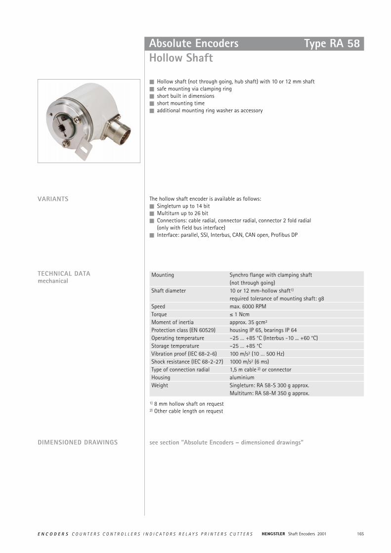
165E N C O D E R S C O U N T E R S C O N T R O L L E R S I N D I C A T O R S R E L A Y S P R I N T E R S C U T T E R S Shaft Encoders 2001
n Hollow shaft (not through going, hub shaft) with 10 or 12 mm shaftn safe mounting via clamping ringn short built in dimensionsn short mounting timen additional mounting ring washer as accessory
VARIANTS The hollow shaft encoder is available as follows: n Singleturn up to 14 bitn Multiturn up to 26 bitn Connections: cable radial, connector radial, connector 2 fold radial
(only with field bus interface)n Interface: parallel, SSI, Interbus, CAN, CAN open, Profibus DP
Absolute EncodersHollow Shaft
Type RA 58
TECHNICAL DATAmechanical
Mounting Synchro flange with clamping shaft (not through going)
Shaft diameter 10 or 12 mm-hollow shaft1)
required tolerance of mounting shaft: g8Speed max. 6000 RPMTorque ² 1 NcmMoment of inertia approx. 35 gcm2
Protection class (EN 60529) housing IP 65, bearings IP 64Operating temperature –25 … +85 °C (Interbus -10 ... +60 °C)Storage temperature –25 … +85 °CVibration proof (IEC 68-2-6) 100 m/s2 (10 … 500 Hz)Shock resistance (IEC 68-2-27) 1000 m/s2 (6 ms)Type of connection radial 1,5 m cable 2) or connectorHousing aluminiumWeight Singleturn: RA 58-S 300 g approx.
Multiturn: RA 58-M 350 g approx.
1) 8 mm hollow shaft on request2) Other cable length on request
DIMENSIONED DRAWINGS see section ”Absolute Encoders – dimensioned drawings”
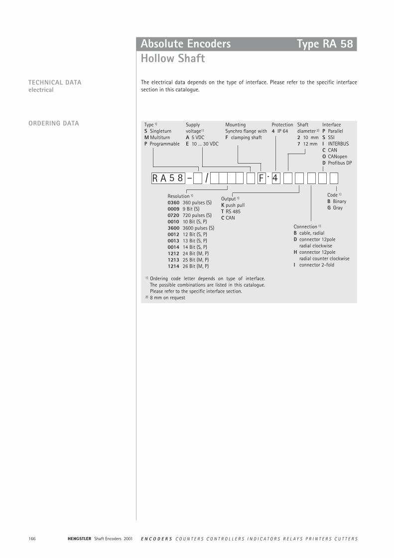
Shaft Encoders 2001166 E N C O D E R S C O U N T E R S C O N T R O L L E R S I N D I C A T O R S R E L A Y S P R I N T E R S C U T T E R S
ORDERING DATA
Absolute Encoders Hollow Shaft
Type RA 58
TECHNICAL DATAelectrical
The electrical data depends on the type of interface. Please refer to the specific interface section in this catalogue.
5 8 – 4·/
Type 1)
S SingleturnM MultiturnP Programmable
Supplyvoltage1)
A 5 VDCE 10 … 30 VDC
MountingSynchro flange withF clamping shaft
Protection4 IP 64
Shaftdiameter 2)
2 10 mm7 12 mm
Output 1)
K push pullT RS 485C CAN
Connection 1)
B cable, radialD connector 12pole
radial clockwiseH connector 12pole
radial counter clockwiseI connector 2-fold
InterfaceP ParallelS SSII INTERBUSC CANO CANopenD Profibus DP
FR A
Resolution 1)
0360 360 pulses (S)0009 9 Bit (S)0720 720 pulses (S)0010 10 Bit (S, P)3600 3600 pulses (S)0012 12 Bit (S, P)0013 13 Bit (S, P)0014 14 Bit (S, P)1212 24 Bit (M, P)1213 25 Bit (M, P)1214 26 Bit (M, P)
Code 1)
B BinaryG Gray
1) Ordering code letter depends on type of interface.The possible combinations are listed in this catalogue.Please refer to the specific interface section.
2) 8 mm on request
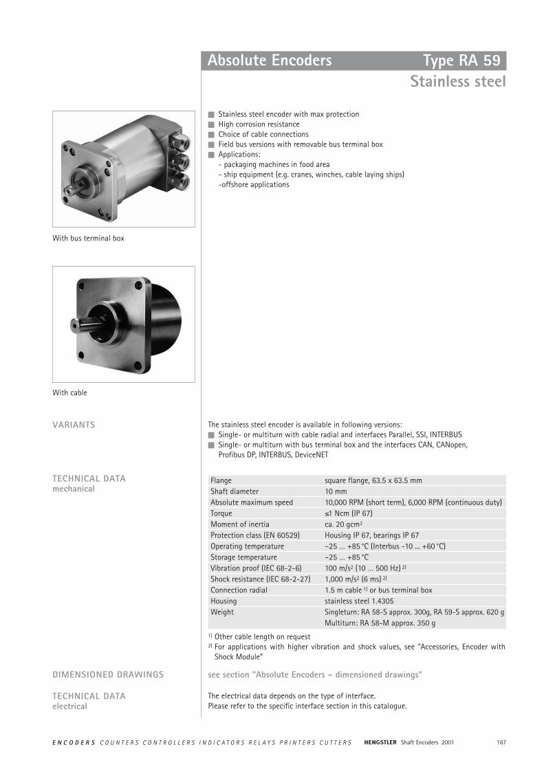
167E N C O D E R S C O U N T E R S C O N T R O L L E R S I N D I C A T O R S R E L A Y S P R I N T E R S C U T T E R S Shaft Encoders 2001
Absolute Encoders Type RA 59Stainless steel
n Stainless steel encoder with max protectionn High corrosion resistancen Choice of cable connectionsn Field bus versions with removable bus terminal boxn Applications:
- packaging machines in food area- ship equipment (e.g. cranes, winches, cable laying ships)-offshore applications
VARIANTS The stainless steel encoder is available in following versions: n Single- or multiturn with cable radial and interfaces Parallel, SSI, INTERBUSn Single- or multiturn with bus terminal box and the interfaces CAN, CANopen,
Profibus DP, INTERBUS, DeviceNET
With bus terminal box
With cable
TECHNICAL DATAelectrical
The electrical data depends on the type of interface.Please refer to the specific interface section in this catalogue.
TECHNICAL DATAmechanical
Flange square flange, 63.5 x 63.5 mmShaft diameter 10 mmAbsolute maximum speed 10,000 RPM (short term), 6,000 RPM (continuous duty)Torque ²1 Ncm (IP 67)Moment of inertia ca. 20 gcm2
Protection class (EN 60529) Housing IP 67, bearings IP 67Operating temperature –25 … +85 °C (Interbus -10 ... +60 °C)Storage temperature –25 … +85 °CVibration proof (IEC 68-2-6) 100 m/s2 (10 … 500 Hz) 2)
Shock resistance (IEC 68-2-27) 1,000 m/s2 (6 ms) 2)
Connection radial 1.5 m cable 1) or bus terminal boxHousing stainless steel 1.4305Weight Singleturn: RA 58-S approx. 300g, RA 59-S approx. 620 g
Multiturn: RA 58-M approx. 350 g1) Other cable length on request2) For applications with higher vibration and shock values, see ”Accessories, Encoder with
Shock Module”
DIMENSIONED DRAWINGS see section ”Absolute Encoders – dimensioned drawings”
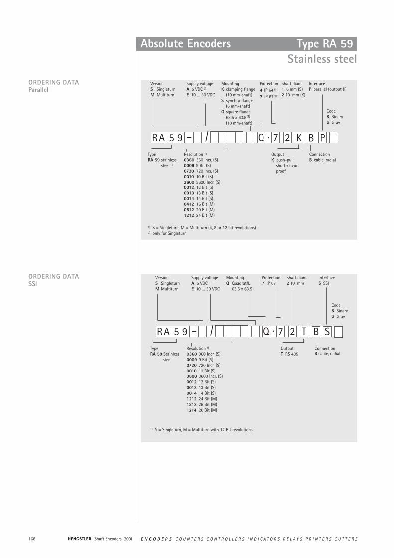
Shaft Encoders 2001168 E N C O D E R S C O U N T E R S C O N T R O L L E R S I N D I C A T O R S R E L A Y S P R I N T E R S C U T T E R S
Absolute Encoders Type RA 59Stainless steel
K BRA 5 9 – 7·/
VersionS SingleturnM Multiturn
Supply voltageA 5 VDC 2)
E 10 … 30 VDC
MountingK clamping flange
(10 mm-shaft)S synchro flange
(6 mm-shaft)Q square flange
63.5 x 63.5 3)
(10 mm-shaft)
Protection4 IP 64 5)
7 IP 67 3)
Shaft diam.1 6 mm (S)2 10 mm (K)
OutputK push-pull
short-circuit proof
ConnectionB cable, radial
P
InterfaceP parallel (output K)
CodeB BinaryG Gray
Type RA 59 stainless
steel 1)
1) S = Singleturn, M = Multiturn (4, 8 or 12 bit revolutions)2) only for Singleturn
ORDERING DATAParallel
Resolution 1)
0360 360 Incr. (S)0009 9 Bit (S)0720 720 Incr. (S)0010 10 Bit (S)3600 3600 Incr. (S)0012 12 Bit (S)0013 13 Bit (S)0014 14 Bit (S)0412 16 Bit (M)0812 20 Bit (M)1212 24 Bit (M)
Q 2
2 T BRA 5 9 – 7·/Resolution 1)
0360 360 Incr. (S) 0009 9 Bit (S)0720 720 Incr. (S) 0010 10 Bit (S) 3600 3600 Incr. (S) 0012 12 Bit (S) 0013 13 Bit (S)0014 14 Bit (S)1212 24 Bit (M)1213 25 Bit (M)1214 26 Bit (M)
VersionS SingleturnM Multiturn
Supply voltageA 5 VDCE 10 … 30 VDC
MountingQ Quadratfl.
63.5 x 63.5
Protection7 IP 67
Shaft diam.2 10 mm
OutputT RS 485
ConnectionB cable, radial
S
InterfaceS SSI
CodeB BinaryG Gray
Q
1) S = Singleturn, M = Multiturn with 12 Bit revolutions
Type RA 59 Stainless
steel
ORDERING DATASSI
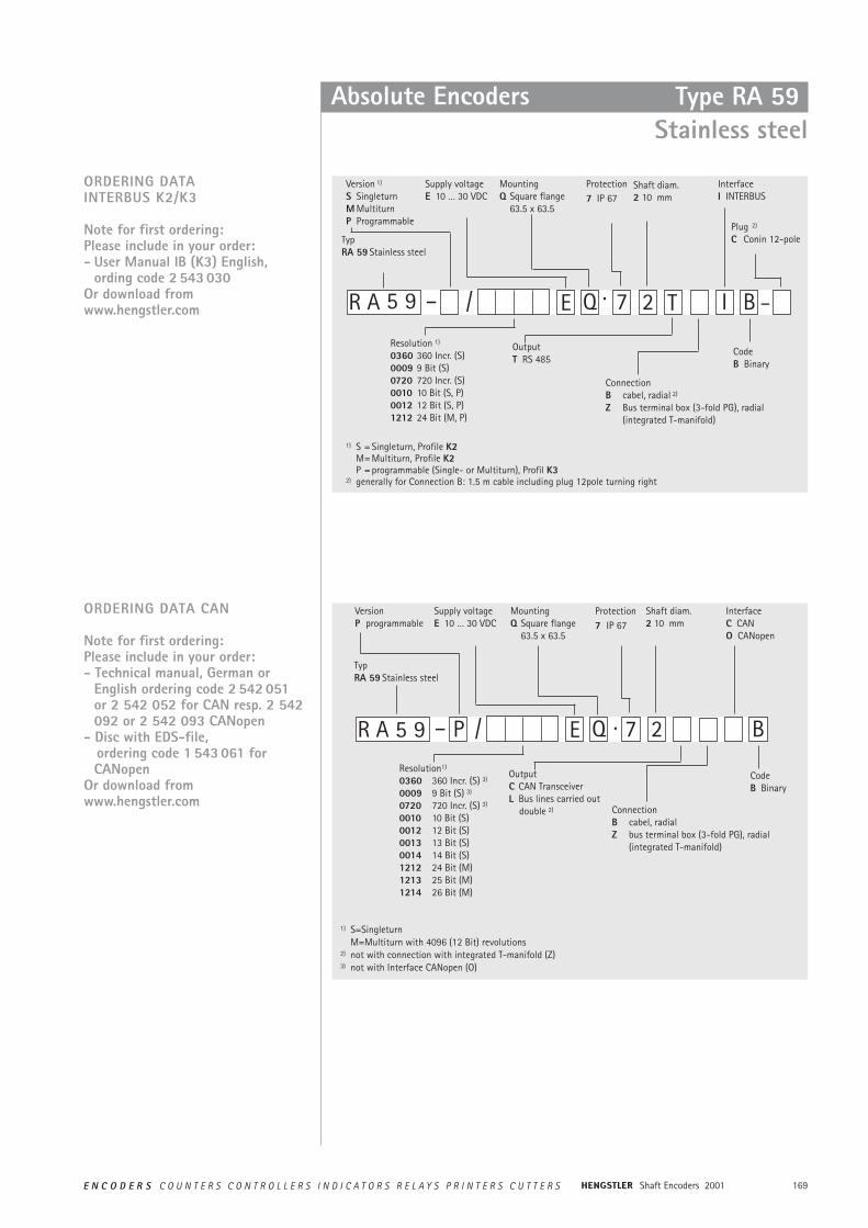
169E N C O D E R S C O U N T E R S C O N T R O L L E R S I N D I C A T O R S R E L A Y S P R I N T E R S C U T T E R S Shaft Encoders 2001
Absolute Encoders Type RA 59Stainless steel
ORDERING DATAINTERBUS K2/K3
Note for first ordering:Please include in your order:- User Manual IB (K3) English,
ording code 2 543 030Or download fromwww.hengstler.com Q 25 9 – 7·/
Version 1)
S SingleturnM MultiturnP Programmable
Supply voltageE 10 … 30 VDC
MountingQ Square flange
63.5 x 63.5
Protection7 IP 67
OutputT RS 485
ConnectionB cabel, radial 2)
Z Bus terminal box (3-fold PG), radial (integrated T-manifold)
I B
InterfaceI INTERBUS
CodeB Binary
E TR A
Resolution 1)
0360 360 Incr. (S)0009 9 Bit (S)0720 720 Incr. (S)0010 10 Bit (S, P)0012 12 Bit (S, P)1212 24 Bit (M, P)
1) S = Singleturn, Profile K2M= Multiturn, Profile K2P = programmable (Single- or Multiturn), Profil K3
2) generally for Connection B: 1.5 m cable including plug 12pole turning right
Typ RA 59 Stainless steel
Shaft diam.2 10 mm
Plug 2)
C Conin 12-pole
–
ORDERING DATA CAN
Note for first ordering:Please include in your order:- Technical manual, German or
English ordering code 2 542 051or 2 542 052 for CAN resp. 2 542092 or 2 542 093 CANopen
- Disc with EDS-file,ordering code 1 543 061 forCANopen
Or download fromwww.hengstler.com
P Q 7 25 9 – ·/
VersionP programmable
Supply voltageE 10 … 30 VDC
MountingQ Square flange
63.5 x 63.5
Protection7 IP 67
Shaft diam.2 10 mm
OutputC CAN TransceiverL Bus lines carried out
double 2) ConnectionB cabel, radialZ bus terminal box (3-fold PG), radial
(integrated T-manifold)
B
InterfaceC CANO CANopen
CodeB Binary
ER A
Resolution1)
0360 360 Incr. (S) 3)
0009 9 Bit (S) 3)
0720 720 Incr. (S) 3)
0010 10 Bit (S)0012 12 Bit (S)0013 13 Bit (S)0014 14 Bit (S)1212 24 Bit (M)1213 25 Bit (M)1214 26 Bit (M)
1) S=SingleturnM=Multiturn with 4096 (12 Bit) revolutions
2) not with connection with integrated T-manifold (Z) 3) not with Interface CANopen (O)
Typ RA 59 Stainless steel
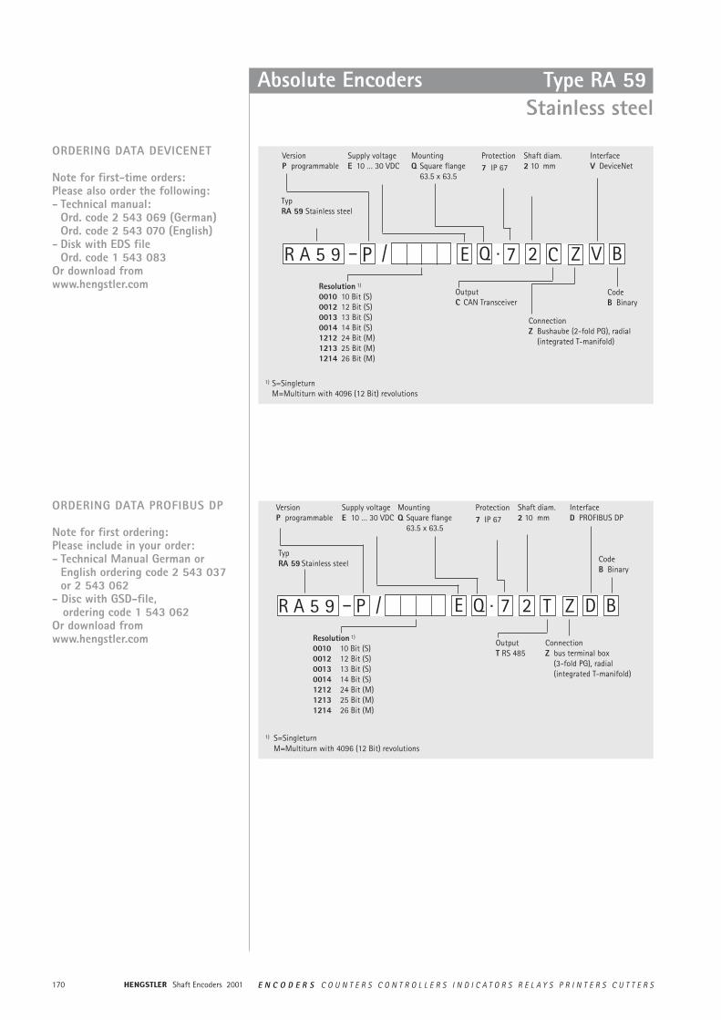
Shaft Encoders 2001170 E N C O D E R S C O U N T E R S C O N T R O L L E R S I N D I C A T O R S R E L A Y S P R I N T E R S C U T T E R S
Absolute Encoders Type RA 59Stainless steel
Q 2 Z5 9 – P 7·/
VersionP programmable
Supply voltageE 10 … 30 VDC
MountingQ Square flange
63.5 x 63.5
Protection7 IP 67
Shaft diam.2 10 mm
OutputC CAN Transceiver
ConnectionZ Bushaube (2-fold PG), radial
(integrated T-manifold)
V B
InterfaceV DeviceNet
CodeB Binary
E CR A
Resolution 1)
0010 10 Bit (S)0012 12 Bit (S)0013 13 Bit (S)0014 14 Bit (S)1212 24 Bit (M)1213 25 Bit (M)1214 26 Bit (M)
1) S=SingleturnM=Multiturn with 4096 (12 Bit) revolutions
Typ RA 59 Stainless steel
ORDERING DATA DEVICENET
Note for first-time orders:Please also order the following:- Technical manual:
Ord. code 2 543 069 (German) Ord. code 2 543 070 (English)
- Disk with EDS fileOrd. code 1 543 083
Or download fromwww.hengstler.com
ORDERING DATA PROFIBUS DP
Note for first ordering:Please include in your order:- Technical Manual German or
English ordering code 2 543 037or 2 543 062
- Disc with GSD-file,ordering code 1 543 062
Or download fromwww.hengstler.com
Q 7 2 Z5 9 – P ·/
VersionP programmable
Supply voltageE 10 … 30 VDC
MountingQ Square flange
63.5 x 63.5
Protection7 IP 67
Shaft diam.2 10 mm
OutputT RS 485
ConnectionZ bus terminal box
(3-fold PG), radial (integrated T-manifold)
D B
InterfaceD PROFIBUS DP
CodeB Binary
E TR A
Resolution 1)
0010 10 Bit (S)0012 12 Bit (S)0013 13 Bit (S)0014 14 Bit (S)1212 24 Bit (M)1213 25 Bit (M)1214 26 Bit (M)
1) S=SingleturnM=Multiturn with 4096 (12 Bit) revolutions
Typ RA 59 Stainless steel
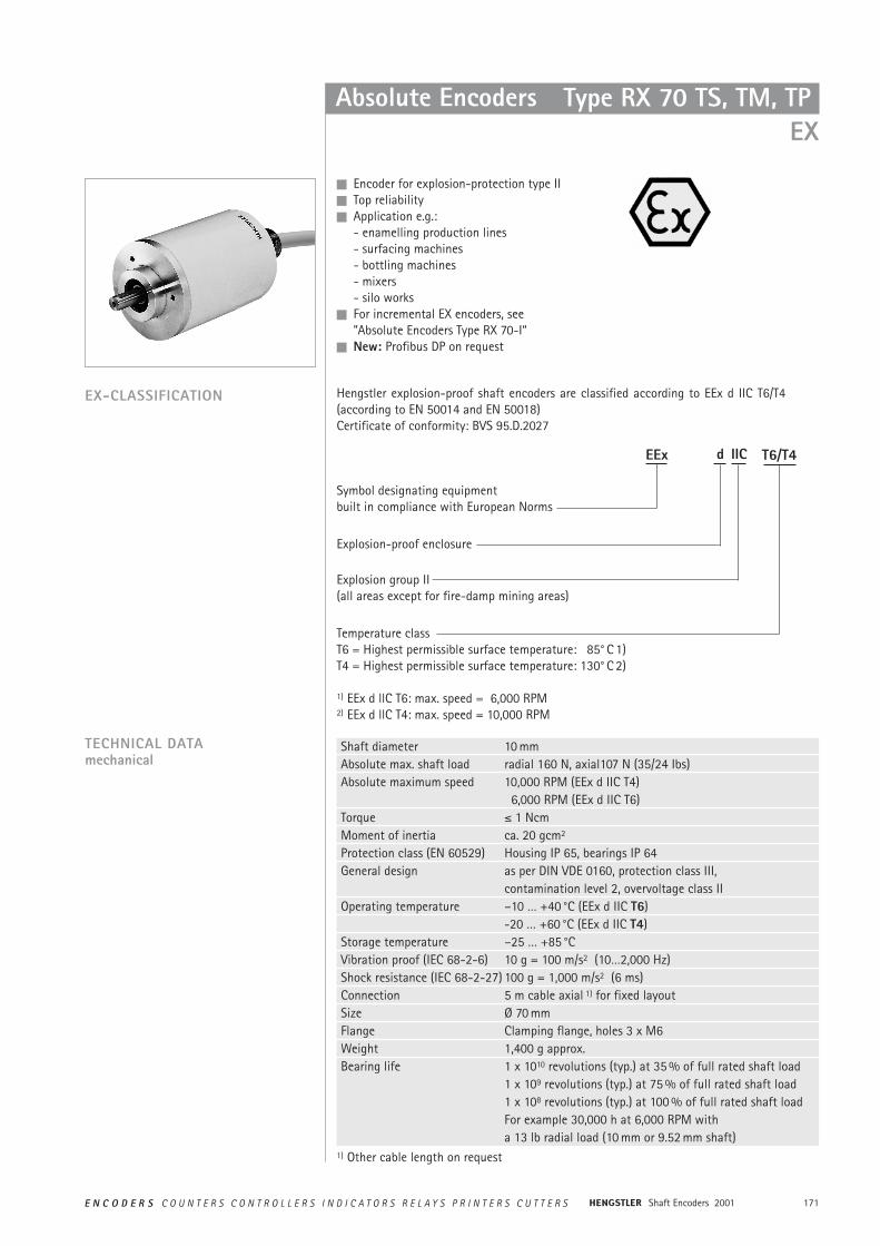
171E N C O D E R S C O U N T E R S C O N T R O L L E R S I N D I C A T O R S R E L A Y S P R I N T E R S C U T T E R S Shaft Encoders 2001
Temperature classT6 = Highest permissible surface temperature: 85° C 1)T4 = Highest permissible surface temperature: 130° C 2)
1) EEx d llC T6: max. speed = 6,000 RPM2) EEx d llC T4: max. speed = 10,000 RPM
Explosion group II(all areas except for fire-damp mining areas)
Absolute Encoders
TECHNICAL DATAmechanical
n Encoder for explosion-protection type IIn Top reliabilityn Application e.g.:
- enamelling production lines- surfacing machines- bottling machines- mixers- silo works
n For incremental EX encoders, see ”Absolute Encoders Type RX 70-I“
n New: Profibus DP on request
EX-CLASSIFICATION Hengstler explosion-proof shaft encoders are classified according to EEx d IIC T6/T4(according to EN 50014 and EN 50018)Certificate of conformity: BVS 95.D.2027
Symbol designating equipment built in compliance with European Norms
EEx d IIC T6/T4
Explosion-proof enclosure
Shaft diameter 10 mm Absolute max. shaft load radial 160 N, axial107 N (35/24 Ibs)Absolute maximum speed 10,000 RPM (EEx d IIC T4)
6,000 RPM (EEx d IIC T6)Torque ² 1 Ncm Moment of inertia ca. 20 gcm2
Protection class (EN 60529) Housing IP 65, bearings IP 64General design as per DIN VDE 0160, protection class III,
contamination level 2, overvoltage class IIOperating temperature –10 … +40 °C (EEx d IIC T6)
-20 … +60 °C (EEx d IIC T4)Storage temperature –25 … +85 °CVibration proof (IEC 68-2-6) 10 g = 100 m/s2 (10…2,000 Hz)Shock resistance (IEC 68-2-27) 100 g = 1,000 m/s2 (6 ms)Connection 5 m cable axial 1) for fixed layoutSize Ø 70 mmFlange Clamping flange, holes 3 x M6Weight 1,400 g approx.Bearing life 1 x 10¹⁰ revolutions (typ.) at 35 % of full rated shaft load
1 x 10⁹ revolutions (typ.) at 75 % of full rated shaft load1 x 108 revolutions (typ.) at 100 % of full rated shaft loadFor example 30,000 h at 6,000 RPM witha 13 lb radial load (10 mm or 9.52 mm shaft)
Type RX 70 TS, TM, TPEX
1) Other cable length on request
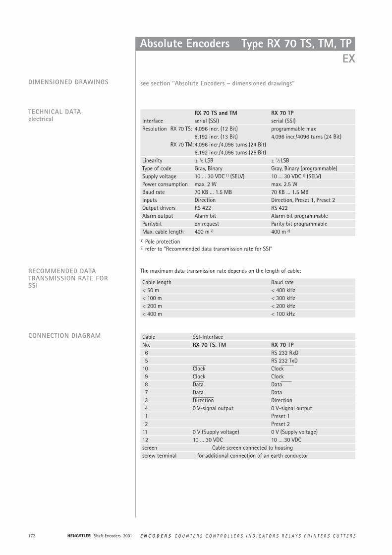
Shaft Encoders 2001172 E N C O D E R S C O U N T E R S C O N T R O L L E R S I N D I C A T O R S R E L A Y S P R I N T E R S C U T T E R S
Absolute Encoders Type RX 70 TS, TM, TP EX
CONNECTION DIAGRAM
RECOMMENDED DATATRANSMISSION RATE FORSSI
TECHNICAL DATAelectrical
DIMENSIONED DRAWINGS see section ”Absolute Encoders – dimensioned drawings”
Cable SSI-InterfaceNo. RX 70 TS, TM RX 70 TP6 RS 232 RxD5 RS 232 TxD
10 Clock Clock9 Clock Clock8 Data Data7 Data Data3 Direction Direction4 0 V-signal output 0 V-signal output1 Preset 12 Preset 2
11 0 V (Supply voltage) 0 V (Supply voltage)12 10 … 30 VDC 10 … 30 VDCscreen Cable screen connected to housingscrew terminal for additional connection of an earth conductor
RX 70 TS and TM RX 70 TPInterface serial (SSI) serial (SSI)Resolution RX 70 TS: 4,096 incr. (12 Bit) programmable max
8,192 incr. (13 Bit) 4,096 incr./4096 turns (24 Bit)RX 70 TM:4,096 incr./4,096 turns (24 Bit)
8,192 incr./4,096 turns (25 Bit)Linearity ± 1⁄2 LSB ± 1⁄2 LSBType of code Gray, Binary Gray, Binary (programmable)Supply voltage 10 … 30 VDC 1) (SELV) 10 … 30 VDC 1) (SELV)Power consumption max. 2 W max. 2.5 WBaud rate 70 KB … 1.5 MB 70 KB … 1.5 MBInputs Direction Direction, Preset 1, Preset 2Output drivers RS 422 RS 422Alarm output Alarm bit Alarm bit programmableParitybit on request Parity bit programmableMax. cable length 400 m 2) 400 m 2)
Cable length Baud rate< 50 m < 400 kHz< 100 m < 300 kHz< 200 m < 200 kHz< 400 m < 100 kHz
The maximum data transmission rate depends on the length of cable:
1) Pole protection2) refer to ”Recommended data transmission rate for SSI”
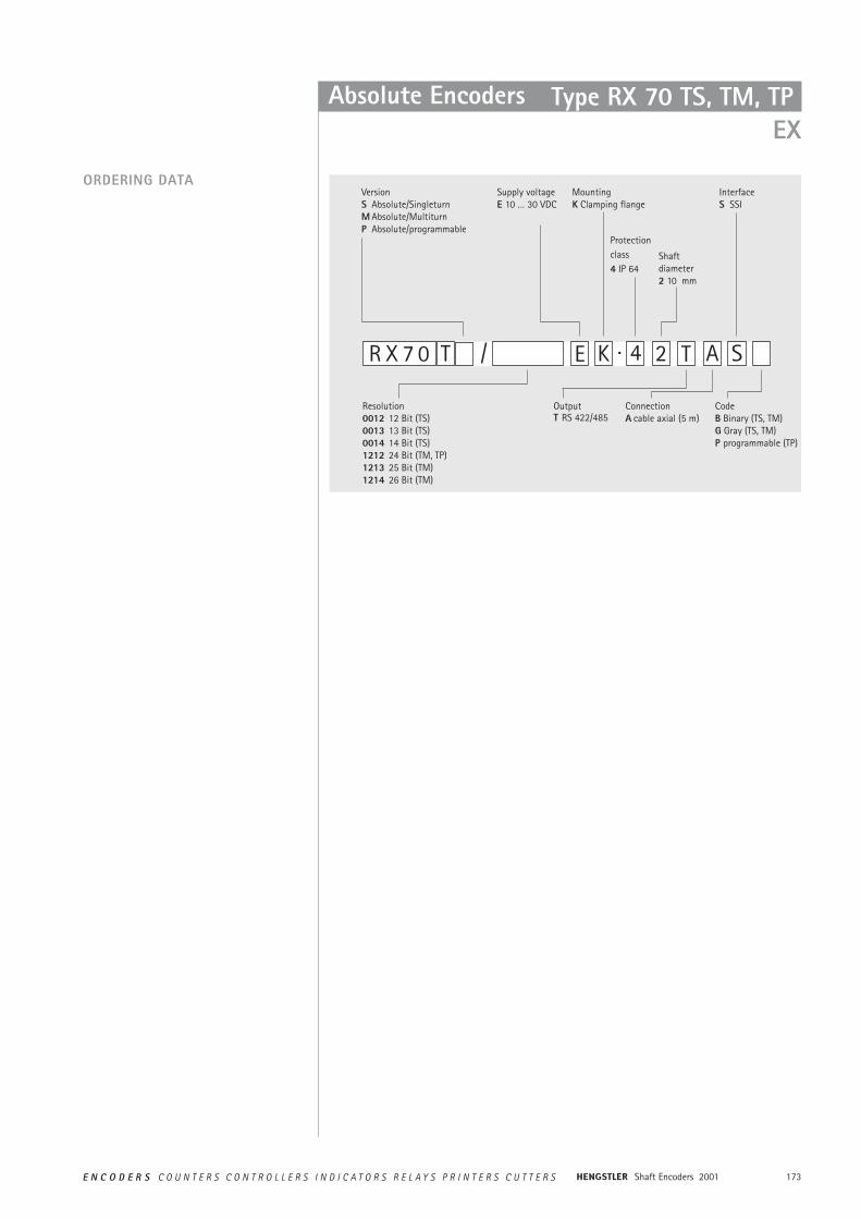
173E N C O D E R S C O U N T E R S C O N T R O L L E R S I N D I C A T O R S R E L A Y S P R I N T E R S C U T T E R S Shaft Encoders 2001
Absolute Encoders
ORDERING DATAVersionS Absolute/SingleturnM Absolute/MultiturnP Absolute/programmable
Supply voltageE 10 … 30 VDC
MountingK Clamping flange
Protectionclass4 IP 64
Shaft diameter2 10 mm
OutputT RS 422/485
ConnectionA cable axial (5 m)
InterfaceS SSI
CodeB Binary (TS, TM)G Gray (TS, TM)P programmable (TP)
Resolution0012 12 Bit (TS)0013 13 Bit (TS)0014 14 Bit (TS)1212 24 Bit (TM, TP)1213 25 Bit (TM)1214 26 Bit (TM)
R X 7 0 T K 2 A4·/ SE T
Type RX 70 TS, TM, TP EX
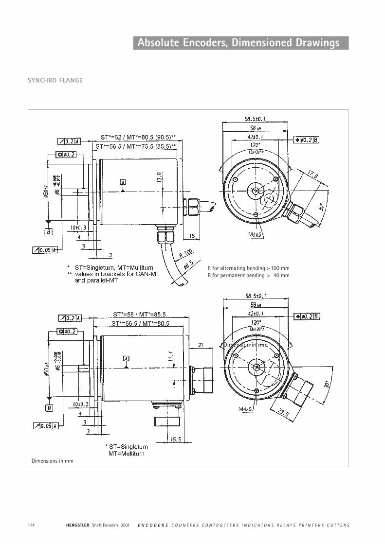
Shaft Encoders 2001174 E N C O D E R S C O U N T E R S C O N T R O L L E R S I N D I C A T O R S R E L A Y S P R I N T E R S C U T T E R S
Absolute Encoders, Dimensioned Drawings
SYNCHRO FLANGE
R for alternating bending > 100 mmR for permanent bending > 40 mm
Dimensions in mm
Dimension in mm
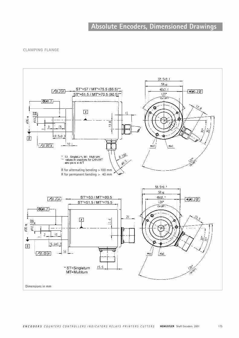
175E N C O D E R S C O U N T E R S C O N T R O L L E R S I N D I C A T O R S R E L A Y S P R I N T E R S C U T T E R S Shaft Encoders 2001
Absolute Encoders, Dimensioned Drawings
CLAMPING FLANGE
Dimensions in mm
R for alternating bending > 100 mmR for permanent bending > 40 mm
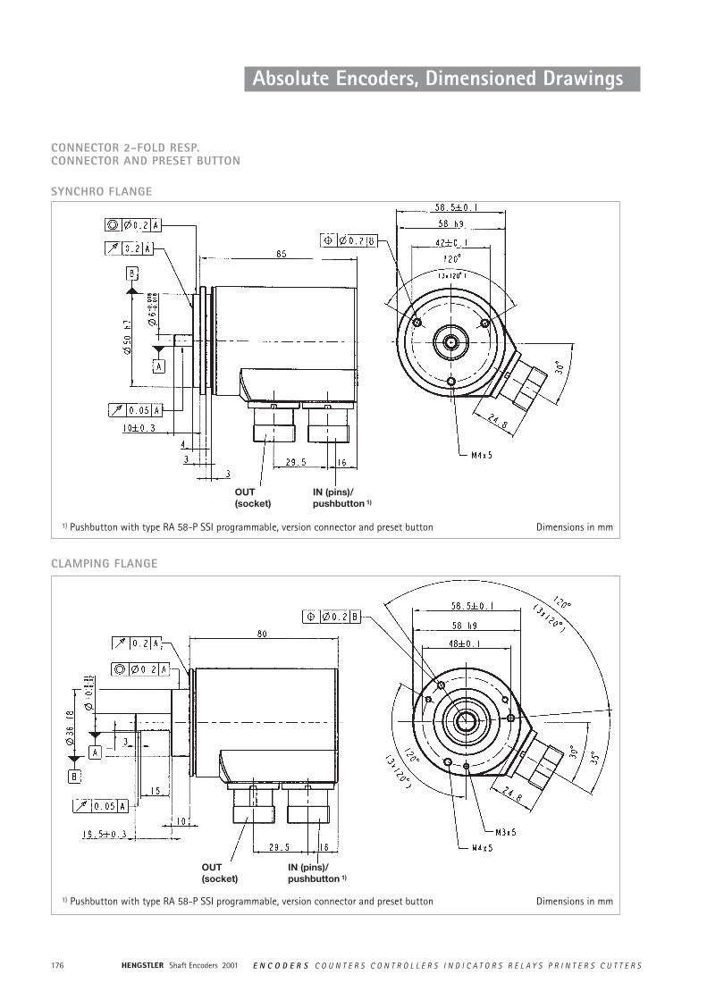
Shaft Encoders 2001176 E N C O D E R S C O U N T E R S C O N T R O L L E R S I N D I C A T O R S R E L A Y S P R I N T E R S C U T T E R S
Absolute Encoders, Dimensioned Drawings
CONNECTOR 2-FOLD RESP.CONNECTOR AND PRESET BUTTON
SYNCHRO FLANGE
IN (pins)/pushbutton 1)
OUT(socket)
1) Pushbutton with type RA 58-P SSI programmable, version connector and preset button
OUT(socket)
IN (pins)/pushbutton 1)
1) Pushbutton with type RA 58-P SSI programmable, version connector and preset button
CLAMPING FLANGE
Dimensions in mm
Dimensions in mm
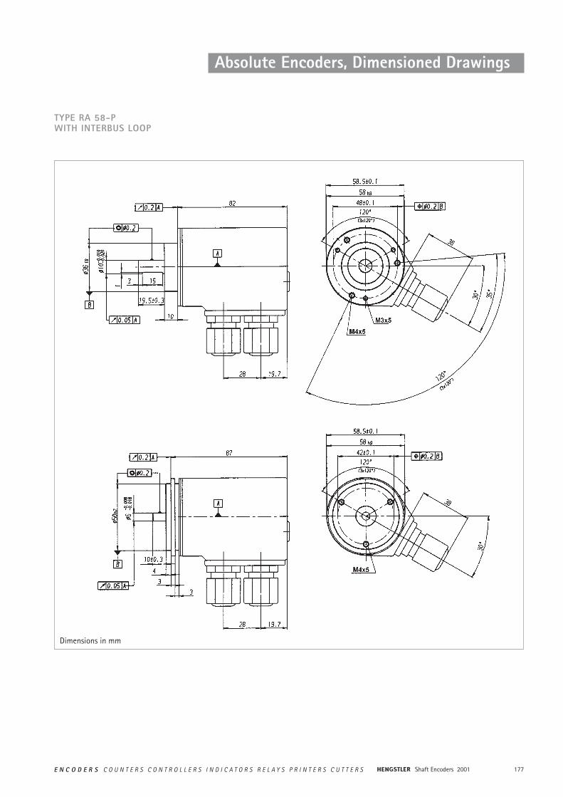
177E N C O D E R S C O U N T E R S C O N T R O L L E R S I N D I C A T O R S R E L A Y S P R I N T E R S C U T T E R S Shaft Encoders 2001
Absolute Encoders, Dimensioned Drawings
TYPE RA 58-P WITH INTERBUS LOOP
Dimensions in mm
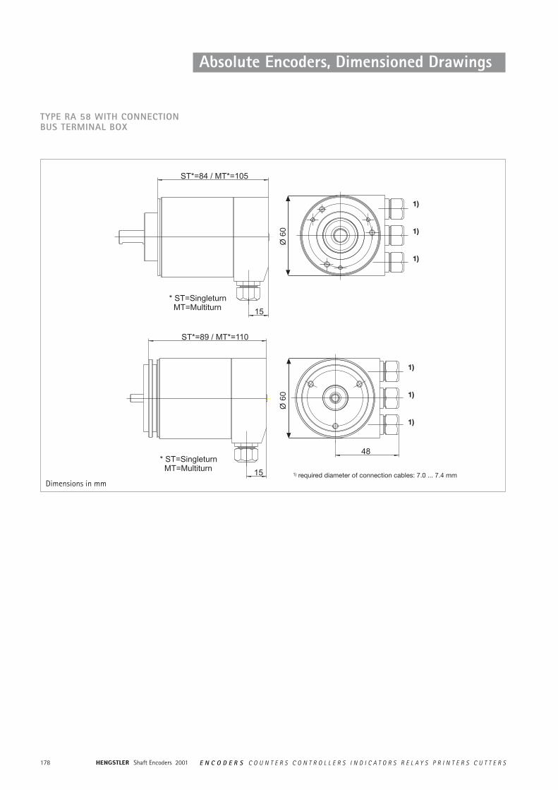
Shaft Encoders 2001178 E N C O D E R S C O U N T E R S C O N T R O L L E R S I N D I C A T O R S R E L A Y S P R I N T E R S C U T T E R S
Absolute Encoders, Dimensioned Drawings
Ø 6
0Ø
60
TYPE RA 58 WITH CONNECTIONBUS TERMINAL BOX
1)
1)
1)
1)
1)
1)
1) required diameter of connection cables: 7.0 ... 7.4 mmDimensions in mm
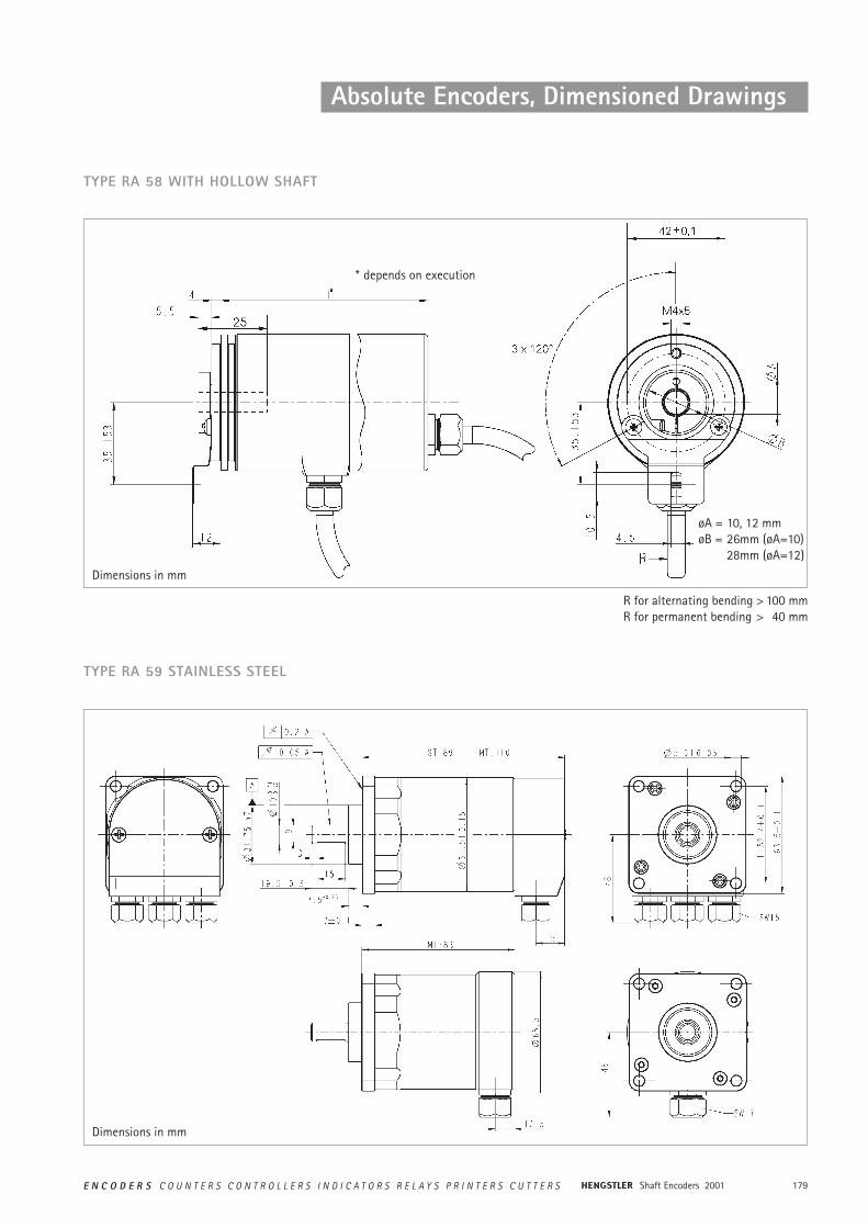
179E N C O D E R S C O U N T E R S C O N T R O L L E R S I N D I C A T O R S R E L A Y S P R I N T E R S C U T T E R S Shaft Encoders 2001
Absolute Encoders, Dimensioned Drawings
* depends on execution
øA = 10, 12 mmøB = 26mm (øA=10)
28mm (øA=12)
TYPE RA 58 WITH HOLLOW SHAFT
TYPE RA 59 STAINLESS STEEL
R for alternating bending > 100 mmR for permanent bending > 40 mm
Dimensions in mm
Dimensions in mm
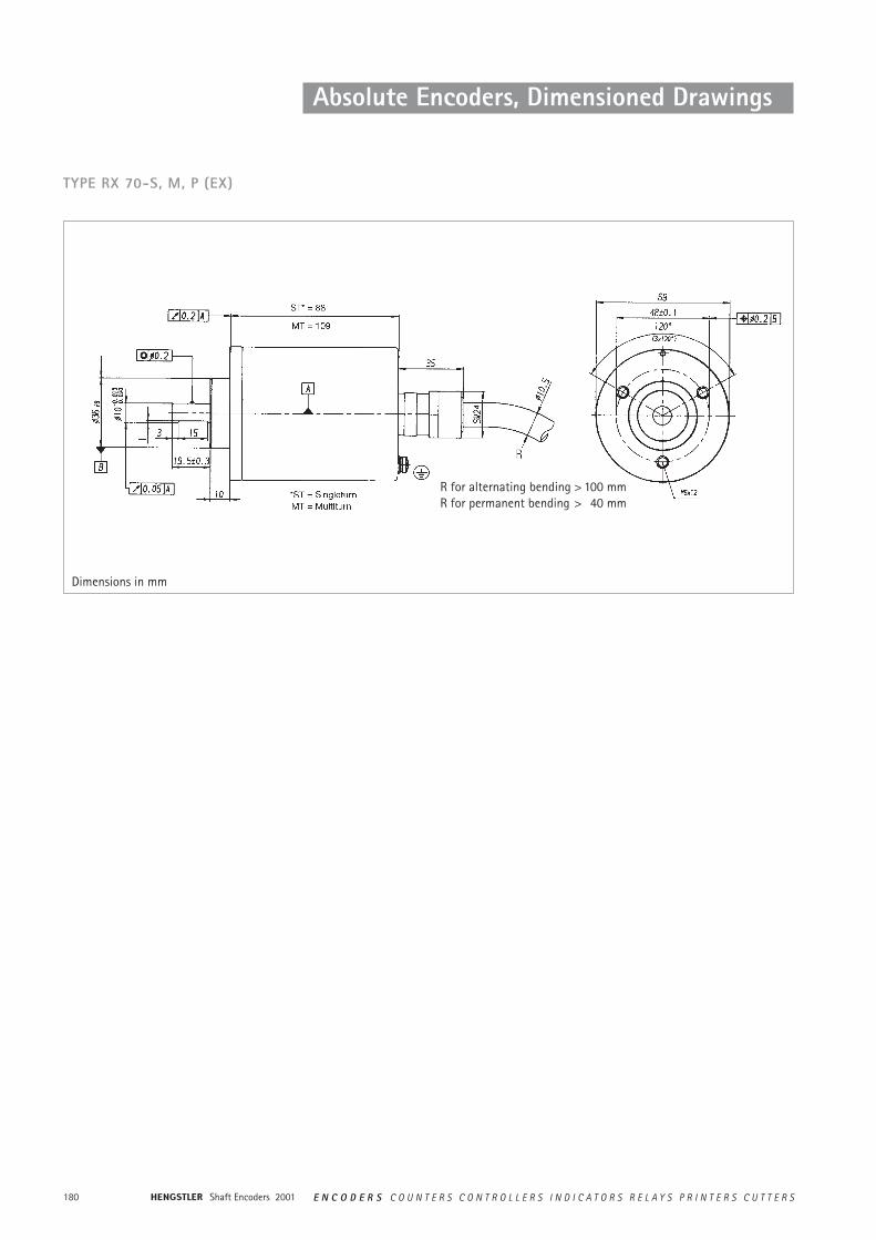
Shaft Encoders 2001180 E N C O D E R S C O U N T E R S C O N T R O L L E R S I N D I C A T O R S R E L A Y S P R I N T E R S C U T T E R S
TYPE RX 70-S, M, P (EX)
Absolute Encoders, Dimensioned Drawings
R for alternating bending > 100 mmR for permanent bending > 40 mm
Dimensions in mm