absolute-encoder cdh75m - etc + fs
TRANSCRIPT
TR-Electronic GmbH
Eglishalde 6
78647 Trossingen
Tel. +49 (0) 7425 228-0
www.tr-electronic.de
Subject to change.
Page 1/5
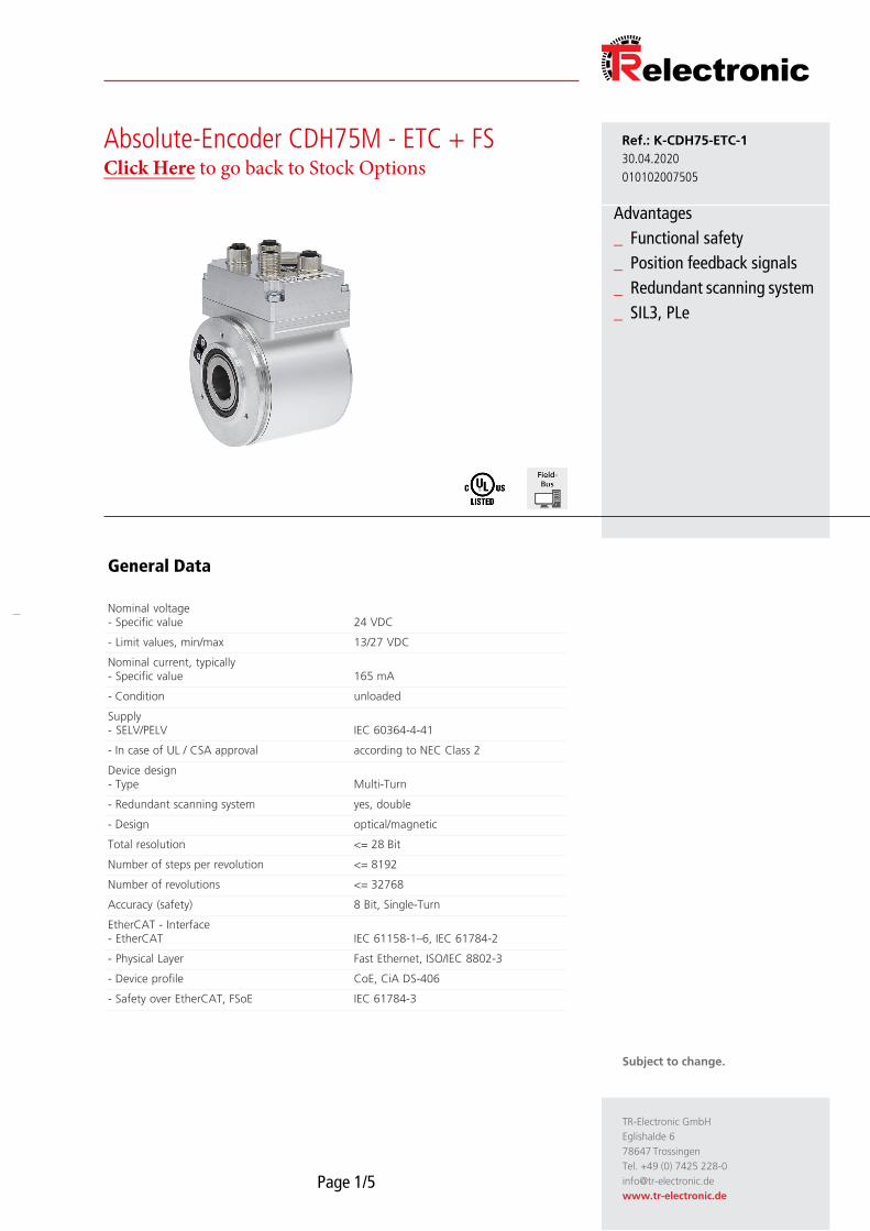
Absolute-Encoder CDH75M - ETC + FSClick Here to go back to Stock Options
Ref.: K-CDH75-ETC-1
30.04.2020
010102007505
Advantages
_ Functional safety
_ Position feedback signals
_ Redundant scanning system
_ SIL3, PLe
General Data
Nominal voltage- Specific value 24 VDC
- Limit values, min/max 13/27 VDC
Nominal current, typically- Specific value 165 mA
- Condition unloaded
Supply- SELV/PELV IEC 60364-4-41
- In case of UL / CSA approval according to NEC Class 2
Device design- Type Multi-Turn
- Redundant scanning system yes, double
- Design optical/magnetic
Total resolution <= 28 Bit
Number of steps per revolution <= 8192
Number of revolutions <= 32768
Accuracy (safety) 8 Bit, Single-Turn
EtherCAT - Interface- EtherCAT IEC 61158-1–6, IEC 61784-2
- Physical Layer Fast Ethernet, ISO/IEC 8802-3
- Device profile CoE, CiA DS-406
- Safety over EtherCAT, FSoE IEC 61784-3
TR-Electronic GmbH
Eglishalde 6
78647 Trossingen
Tel. +49 (0) 7425 228-0
www.tr-electronic.de
Subject to change.
Page 2/5
Absolute-Encoder CDH75M - ETC + FS Ref.: K-CDH75-ETC-1
30.04.2020
010102007505
General Data continuation
Incremental - Interface- Equipment Standard interface
- Signal form Square wave
- Signal form, alternative SIN / COS
- Incremental signals, square K1± K2±
- Incremental signals, SIN/COS SIN± COS±, 1 Vss
- Impulses, square wave 1024…5120, in steps of 1024
- Impulses, square wave 4096…20480, in steps of 4096
- Impulses, SIN/COS
- Output driver, TTL RS-422, 5 VDC
- Output driver, HTL Push-Pull, Supply Voltage
- Type of parametrization Factory setting
Transmission rate- Specific value 100 MBit/s
Cycle time- Not safety related 0.5 ms
- Safety related 5 ms
Parameter/Function, changeable Integration time
Preset parameter
Monitoring window
Counting direction
Velocity parameter
Type of parametrization programmable
Programming - Tool Fieldbus-Device
Functional safety- Safety principle Redundance with cross compare
- SIL-Standardization DIN EN 61508 / DIN EN 62061
- SIL-Level SIL3 / SIL CL 3
- PL-Standardization DIN EN ISO 13849
- Performance-Level (PL) PLe / Cat. 4
- Service life 20 Years
- PFH 3.25E-10 1/h
- PFDav, T = 20 a 2.81E-5
- MTTFd 197 a
- DCavg 98 %
Maximum Speed, mechanically <= 3000 1/min
Shaft load, axial/radial Own mass
Bearing life time >= 3.9E+10 revolutions
TR-Electronic GmbH
Eglishalde 6
78647 Trossingen
Tel. +49 (0) 7425 228-0
www.tr-electronic.de
Subject to change.
Page 3/5
Absolute-Encoder CDH75M - ETC + FS Ref.: K-CDH75-ETC-1
30.04.2020
010102007505
General Data continuation
Bearing life time - Parameter- Speed 1000 1/min
- Operating temperature 50 °C
Shaft type- Shaft diameter [mm] 12
- Shaft diameter [mm] 14
- Shaft diameter [mm] 20
Angular acceleration <= 10E+4 rad/s²
Start-up torque, 20 °C 6 Ncm
Mass, typically 1 kg
Environmental conditions
Vibration- Specific value <= 100 m/s²
- Sine 50…2000 Hz
Shock- Specific value <= 600 m/s²
- Half sine 5 ms
Immunity to disturbance DIN EN 61000-6-2
Transient emissions DIN EN 61000-6-3
Working temperature- Standard Tu = f(n) = -25…+65 °C
Tu for n > 100 1/min, IP54 Tu = f(n) = 65°C – (0.005 * n)
Tu for n > 100 1/min, IP65 Tu = f(n) = 60°C – (0.01 * n)
Storage temperature, dry -30…+80 °C
Relative humidity 98 %, non condensing
Protection class- Standard IP54
- Optional extended to IP65
TR-Electronic GmbH
Eglishalde 6
78647 Trossingen
Tel. +49 (0) 7425 228-0
www.tr-electronic.de
Subject to change.
Page 4/5
Absolute-Encoder CDH75M - ETC + FS Ref.: K-CDH75-ETC-1
30.04.2020
010102007505
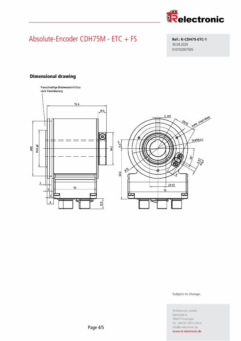
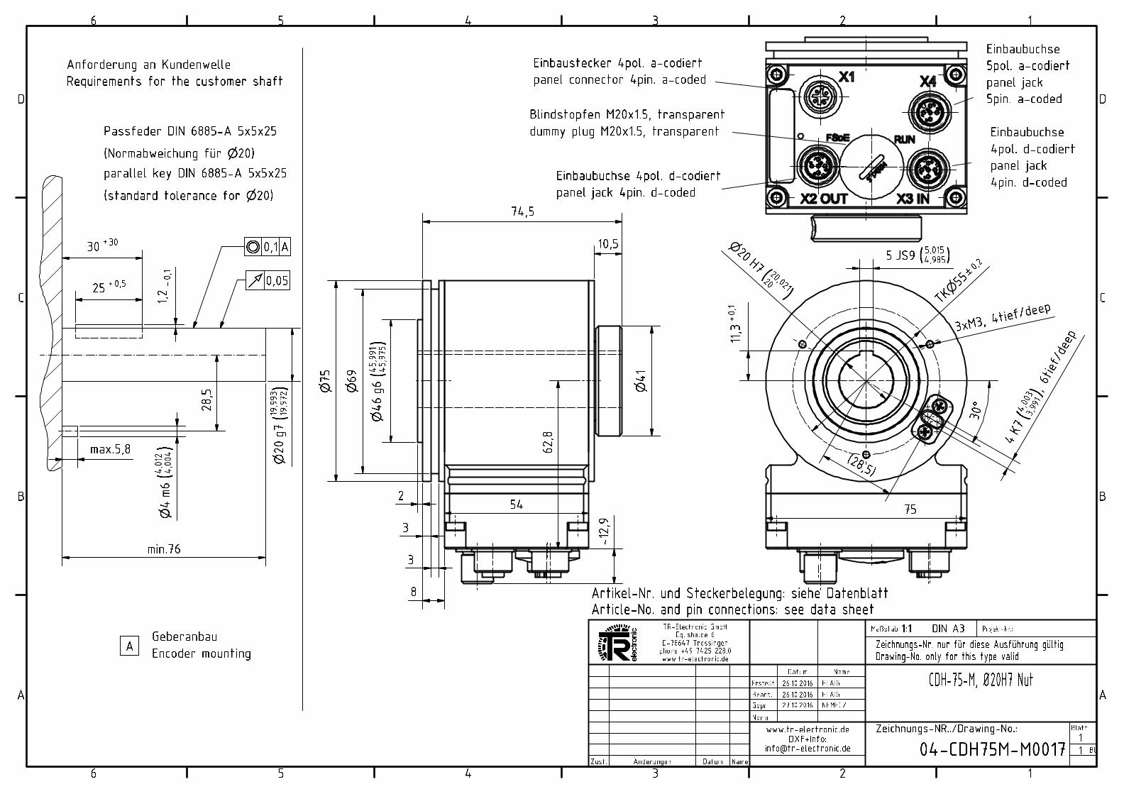
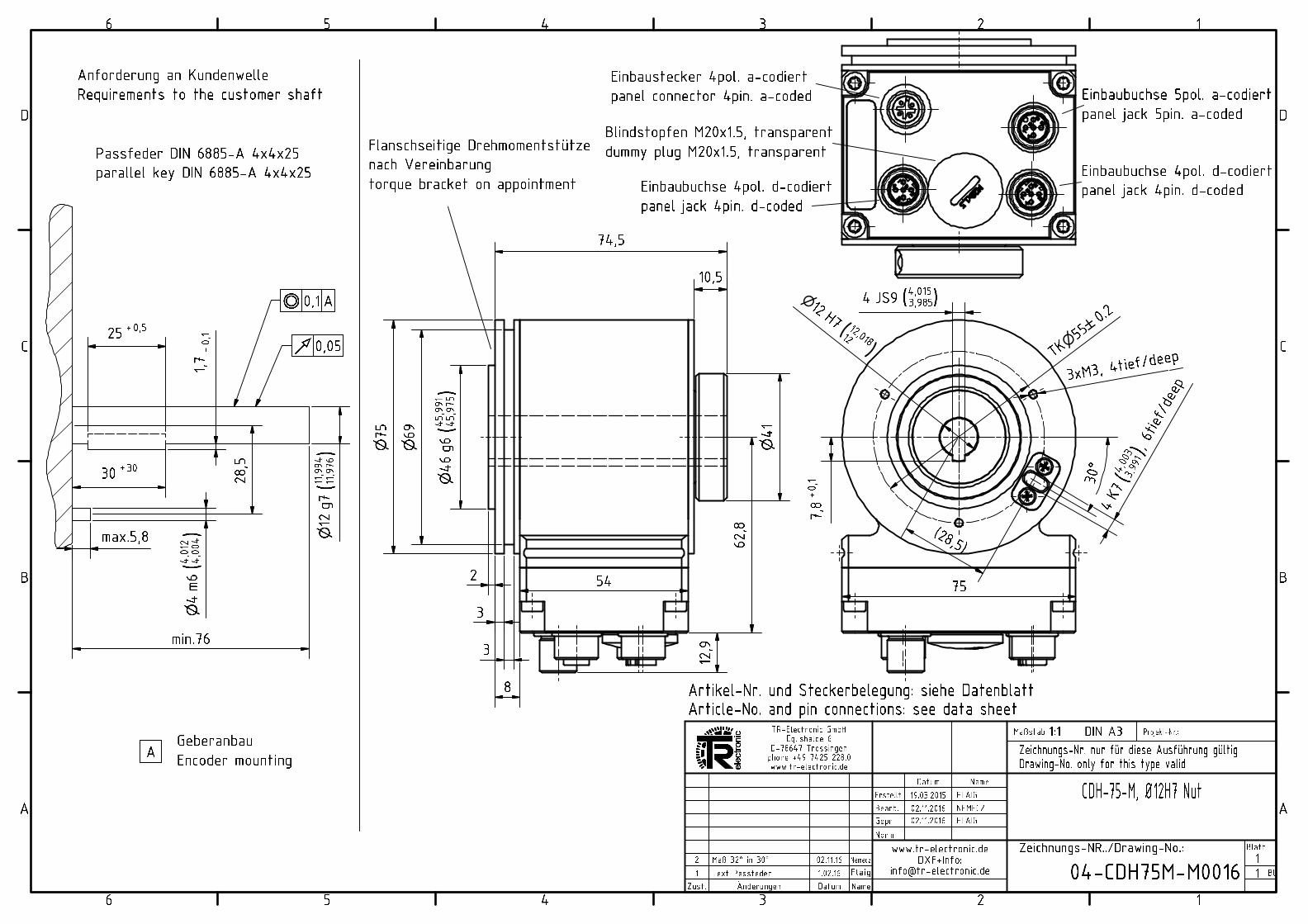
Dimensional drawing
TR-Electronic GmbH
Eglishalde 6
78647 Trossingen
Tel. +49 (0) 7425 228-0
www.tr-electronic.de
Subject to change.
Page 5/5
Absolute-Encoder CDH75M - ETC + FS Ref.: K-CDH75-ETC-1
30.04.2020
010102007505
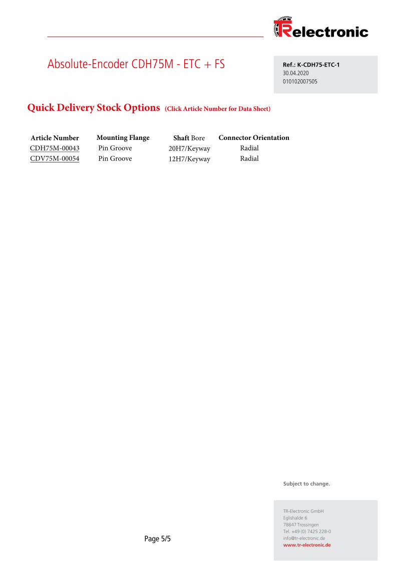
Article Number CDH75M-00043 CDV75M-00054
Mounting Flange Pin GroovePin Groove
Shaft Bore20H7/Keyway 12H7/Keyway
Quick Delivery Stock Options (Click Article Number for Data Sheet)
Connector Orientation RadialRadial
Absolute rotary Encoder
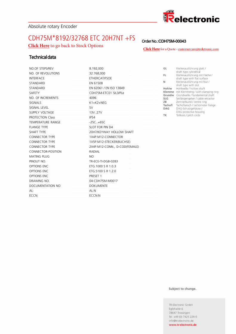
CDH75M*8192/32768 ETC 20H7NT +FSClick Here to go back to Stock Options
Technical data
NO.OF STEPS/REV 8.192,000
NO. OF REVOLUTIONS 32.768,000
INTERFACE ETHERCAT/FSOE
STANDARD EN 61508
STANDARD EN 62061 / EN ISO 13849
SAFETY CDH75M-ETC01 SIL3/PLe
NO. OF INCREMENTS 4096
SIGNALS K1+K2+NEG
SIGNAL LEVEL 5V
SUPPLY VOLTAGE 13V..27V
PROTECTION Class IP54
TEMPERATURE RANGE -25C..+65C
FLANGE TYPE SLOT FOR PIN D4
SHAFT TYPE 20H7/KEYWAY HOLLOW SHAFT
CONNECTOR TYPE 1X4P.M12-CONNECTOR
CONNECTOR TYPE 1X5P.M12-STECKER(BUCHSE)
CONNECTOR TYPE 2X4P.M12-CONN., D-COD(FEMALE)
CONNECTOR-POSITION RADIAL
MATING PLUG NO
PINOUT NO. TR-ECE-TI-DGB-0283
OPTIONS ENC ETG.1000 S R 1.0.3
OPTIONS ENC ETG.5100 S R 1.2.0
OPTIONS ENC PRESET 1
DRAWING NO. 04-CDH75M-M0017
DOCUMENTATION NO DOKUMENTE
AL: AL:N
ECCN: ECCN:N
Order No.:CDH75M-00043
Click Here for a Quote - [email protected]
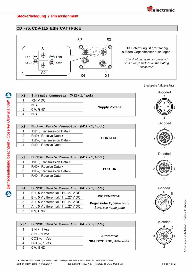
Steckerbelegung / Pin assignment
TR - ELECTRONIC GmbH, Eglishalde 6, 78647 Trossingen, Tel. ++49 (0)7425 / 228-0, Fax ++49 (0)7425 / 228-33
Edition-/Rev.-Date: 11/28/2017 Document-/Rev.-No.: TR-ECE-TI-DGB-0283-03 Page 1 of 2
Änd
erun
gen
vorb
ehal
ten
/ S
ubje
ct to
cha
nge
CD_-75, CDV-115 EtherCAT / FSoE
Die Schirmung ist großflächig auf den Gegenstecker aufzulegen!
The shielding is to be connected
with a large surface on the mating
connector!
Steckseite / Mating Face
X1 Stift / Male Connector (M12 x 1, 4 pol.)
1 +24 V DC
Supply Voltage 2 N.C.3 0 V, GND 4 N.C.
X2 Buchse / Female Connector (M12 x 1, 4 pol.)
1 TxD+, Transmission Data +
PORT-OUT 2 RxD+, Receive Data + 3 TxD–, Transmission Data – 4 RxD–, Receive Data –
X3 Buchse / Female Connector (M12 x 1, 4 pol.)
1 TxD+, Transmission Data +
PORT-IN 2 RxD+, Receive Data + 3 TxD–, Transmission Data – 4 RxD–, Receive Data –
X4 Buchse / Female Connector (M12 x 1, 5 pol.)
1 B +, 5 V differential / 11…27 V DC INCREMENTAL
Pegel siehe Typenschild /
Level see name plate
2 B –, 5 V differential / 11…27 V DC 3 A +, 5 V differential / 11…27 V DC 4 A –, 5 V differential / 11…27 V DC 5 0 V, GND
X4 Buchse / Female Connector (M12 x 1, 5 pol.)
1 SIN +, 1 Vss
Alternative
SINUS/COSINE, differential
2 SIN –, 1 Vss 3 COS +, 1 Vss 4 COS –, 1 Vss 5 0 V, GND
5
3
4
2
1
A-coded
5
3
4
2
1
A-coded
Steckerbelegung / Pin assignment
TR - ELECTRONIC GmbH, Eglishalde 6, 78647 Trossingen, Tel. ++49 (0)7425 / 228-0, Fax ++49 (0)7425 / 228-33
Edition-/Rev.-Date: 11/28/2017 Document-/Rev.-No.: TR-ECE-TI-DGB-0283-03 Page 2 of 2
Änd
erun
gen
vorb
ehal
ten
/ S
ubje
ct to
cha
nge
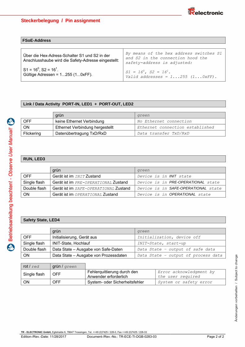
FSoE-Address
Über die Hex-Adress-Schalter S1 und S2 in der Anschlusshaube wird die Safety-Adresse eingestellt:
S1 = 160, S2 = 161.Gültige Adressen = 1...255 (1...0xFF).
By means of the hex address switches S1
and S2 in the connection hood the
safety-address is adjusted:
S1 = 160, S2 = 16
1.
Valid addresses = 1...255 (1...0xFF).
Link / Data Activity PORT-IN, LED1 + PORT-OUT, LED2
grün green
OFF keine Ethernet Verbindung No Ethernet connection
ON Ethernet Verbindung hergestellt Ethernet connection established
Flickering Datenübertragung TxD/RxD Data transfer TxD/RxD
RUN, LED3
grün green
OFF Gerät ist im INIT Zustand Device is in INIT state
Single flash Gerät ist im PRE-OPERATIONAL Zustand Device is in PRE-OPERATIONAL state
Double flash Gerät ist im SAFE-OPERATIONAL Zustand Device is in SAFE-OPERATIONAL state
ON Gerät ist im OPERATIONAL Zustand Device is in OPERATIONAL state
Safety State, LED4
grün green
OFF Initialisierung, Gerät aus Initialization, device off
Single flash INIT-State, Hochlauf INIT-State, start-up
Double flash Data State – Ausgabe von Safe-Daten Data State – output of safe data
ON Data State – Ausgabe von Prozessdaten Data State – output of process data
rot / red grün / green
Single flash OFF Fehlerquittierung durch den Anwender erforderlich
Error acknowledgment by
the user required
ON OFF System- oder Sicherheitsfehler System or safety error
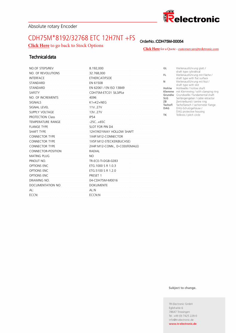
Absolute rotary Encoder
CDH75M*8192/32768 ETC 12H7NT +FSClick Here to go back to Stock Options
Technical data
NO.OF STEPS/REV 8.192,000
NO. OF REVOLUTIONS 32.768,000
INTERFACE ETHERCAT/FSOE
STANDARD EN 61508
STANDARD EN 62061 / EN ISO 13849
SAFETY CDH75M-ETC01 SIL3/PLe
NO. OF INCREMENTS 4096
SIGNALS K1+K2+NEG
SIGNAL LEVEL 11V..27V
SUPPLY VOLTAGE 13V..27V
PROTECTION Class IP54
TEMPERATURE RANGE -25C..+65C
FLANGE TYPE SLOT FOR PIN D4
SHAFT TYPE 12H7/KEYWAY HOLLOW SHAFT
CONNECTOR TYPE 1X4P.M12-CONNECTOR
CONNECTOR TYPE 1X5P.M12-STECKER(BUCHSE)
CONNECTOR TYPE 2X4P.M12-CONN., D-COD(FEMALE)
CONNECTOR-POSITION RADIAL
MATING PLUG NO
PINOUT NO. TR-ECE-TI-DGB-0283
OPTIONS ENC ETG.1000 S R 1.0.3
OPTIONS ENC ETG.5100 S R 1.2.0
OPTIONS ENC PRESET 1
DRAWING NO. 04-CDH75M-M0016
DOCUMENTATION NO DOKUMENTE
AL: AL:N
ECCN: ECCN:N
Order No.:CDH75M-00054
Click Here for a Quote - [email protected]

Steckerbelegung / Pin assignment
TR - ELECTRONIC GmbH, Eglishalde 6, 78647 Trossingen, Tel. ++49 (0)7425 / 228-0, Fax ++49 (0)7425 / 228-33
Edition-/Rev.-Date: 11/28/2017 Document-/Rev.-No.: TR-ECE-TI-DGB-0283-03 Page 1 of 2
Änd
erun
gen
vorb
ehal
ten
/ S
ubje
ct to
cha
nge
CD_-75, CDV-115 EtherCAT / FSoE
Die Schirmung ist großflächig auf den Gegenstecker aufzulegen!
The shielding is to be connected
with a large surface on the mating
connector!
Steckseite / Mating Face
X1 Stift / Male Connector (M12 x 1, 4 pol.)
1 +24 V DC
Supply Voltage 2 N.C. 3 0 V, GND 4 N.C.
X2 Buchse / Female Connector (M12 x 1, 4 pol.)
1 TxD+, Transmission Data +
PORT-OUT 2 RxD+, Receive Data + 3 TxD–, Transmission Data – 4 RxD–, Receive Data –
X3 Buchse / Female Connector (M12 x 1, 4 pol.)
1 TxD+, Transmission Data +
PORT-IN 2 RxD+, Receive Data + 3 TxD–, Transmission Data – 4 RxD–, Receive Data –
X4 Buchse / Female Connector (M12 x 1, 5 pol.)
1 B +, 5 V differential / 11…27 V DC INCREMENTAL
Pegel siehe Typenschild /
Level see name plate
2 B –, 5 V differential / 11…27 V DC 3 A +, 5 V differential / 11…27 V DC 4 A –, 5 V differential / 11…27 V DC 5 0 V, GND
X4 Buchse / Female Connector (M12 x 1, 5 pol.)
1 SIN +, 1 Vss
Alternative
SINUS/COSINE, differential
2 SIN –, 1 Vss 3 COS +, 1 Vss 4 COS –, 1 Vss 5 0 V, GND
5
3
4
2
1
A-coded
5
3
4
2
1
A-coded

Steckerbelegung / Pin assignment
TR - ELECTRONIC GmbH, Eglishalde 6, 78647 Trossingen, Tel. ++49 (0)7425 / 228-0, Fax ++49 (0)7425 / 228-33
Edition-/Rev.-Date: 11/28/2017 Document-/Rev.-No.: TR-ECE-TI-DGB-0283-03 Page 2 of 2
Änd
erun
gen
vorb
ehal
ten
/ S
ubje
ct to
cha
nge
FSoE-Address
Über die Hex-Adress-Schalter S1 und S2 in der Anschlusshaube wird die Safety-Adresse eingestellt: S1 = 160, S2 = 161. Gültige Adressen = 1...255 (1...0xFF).
By means of the hex address switches S1
and S2 in the connection hood the
safety-address is adjusted:
S1 = 160, S2 = 16
1.
Valid addresses = 1...255 (1...0xFF).
Link / Data Activity PORT-IN, LED1 + PORT-OUT, LED2
grün green
OFF keine Ethernet Verbindung No Ethernet connection
ON Ethernet Verbindung hergestellt Ethernet connection established
Flickering Datenübertragung TxD/RxD Data transfer TxD/RxD
RUN, LED3
grün green
OFF Gerät ist im INIT Zustand Device is in INIT state
Single flash Gerät ist im PRE-OPERATIONAL Zustand Device is in PRE-OPERATIONAL state
Double flash Gerät ist im SAFE-OPERATIONAL Zustand Device is in SAFE-OPERATIONAL state
ON Gerät ist im OPERATIONAL Zustand Device is in OPERATIONAL state
Safety State, LED4
grün green
OFF Initialisierung, Gerät aus Initialization, device off
Single flash INIT-State, Hochlauf INIT-State, start-up
Double flash Data State – Ausgabe von Safe-Daten Data State – output of safe data
ON Data State – Ausgabe von Prozessdaten Data State – output of process data
rot / red grün / green
Single flash OFF Fehlerquittierung durch den Anwender erforderlich
Error acknowledgment by
the user required
ON OFF System- oder Sicherheitsfehler System or safety error