heat-trrnsfer performance of polymer 1/2 … uous dropwise condensation in ekcess of 10,000 hours...
TRANSCRIPT

AD-RI54 743 ENDURANCE AND HEAT-TRRNSFER PERFORMANCE OF POLYMER 1/2COATINGS FOR THE PROMO..(U) NAVAL POSTGRADUATE SCHOOLMONTEREY CA D J LOONEY DEC 84 NPS-69-84-015
UNCLASSIFIED F/G 11/3 N
IIIIIIIIIIIIIIhE
II I hhhEEI Ej

11. 02 -
mml
1111 li = Im dg' 2
MICROCOPY RESOLUTION TEST CHARTNATIONAL BUREAU OF STANDARDS-1963-A
.4. * * ~ . ...... . . r,

NAVAL POSTGRADUATE SCHOOL KMonterey, California
ECTE* JN 12 IMU
ENDURANCE AND HEAT-TRANSFER PERFUPJ4ANCEOF POLYMER COAT INFS FOR THE POMOTTON
OF DROPWISE CONDENSATION Or 'T=A'!
by
DanielJ Looney
December 19814
C-
Thesis Advisor: P. J. iMarto
Approved for public release; distribution unlimitel.
Prepar'- d for:National Science Fcun'iatiori* 5 Division of Engineerini,Washington, 11. C. 205SC
8 5. 5 05 0O4

NAVAL 20ST'07ADUATE SCHOCLMonterey, Cali~ornia
Commodore Robert H. Shumaker David A. Sc!'.radvSuperintendent Provost
This thesis prepared in conjunction with researchsupported in part by National Science Foundation, Divisionof Engineering, Washington, DC under MEA82-03567. .. ,A
Reproduction of all or part of this report is authorized.
Released as aTechnical Report by:
John .OeDean of Science andEngineering

UnclassifiedSECURITY CLASSIFICATION OF THIS PAGE (Ufmm, Daener*0..
REPORT DOCUMENTATION PAGE BFRE COSMPLETINORM
1. REPRT NU99A A GOVT ACCESSION NO. S. RECIPIENT'S CATALOG NUMBER
4. TTLE and ublile)S. TYPE OF REPORT A PERIOD COVEREDEndurance and Heat-Transfer Performance Master of Scienceof Polymer Coatings for the Promotion of Thesis; December 1984Dropwise Condensation of Steam 6. PERFORMING ORG. REPORT NUMBER
7. AUTNORI'.) 4. CONTRACT OR GRANT NUMSER(o)-
Daniel J. Looney
S. PERFORMING ORGANIZATION NAME AND ADDRESS 10. PROGRAM ELEMENT. PROJECT. TASK
* ~Naval Postgraduate School AE OKUI USR
Monterey, California 93943 N6.227182WE20114
I I. CONTROLLING OFFICE NAME ANO ADDRESS 12. REPORT DATE
Naval Postgraduate SchoolDembr1813. MUMMER OF PAGESMonterey, California 9394313
%tNITORfCGIFNCY NAME & AOO SEStyd different frm CoftmeoId Office) IS. SECURITY CLASS. (of this rport)Iaona Science Foun a ion
Washington, DC 20550 UnclassifiedDivision of Engineering IaDELASSI FIC ATION/ODOWNGRADING
C OU LE
IS. DISTRIBUTION STATEMENT (of this Report)
* Approved for public release; distribution unlimited.
cOession For
17. DIST RI OUTION ST ATEMEN T (at the abstract entered in block 20. It dI,ifntlbkm A ~DI A
Unanoumoog 0Justileatio -_
III. SUPPLEMENTARY NOTES
jAvail and/or
I9. KEY ORDS (Continue on reverse side It necessary and identity by block numb.t)
Srowise Condensation., -# Fluoroacrylic) 1Polymer Coatings, Parylene (Heat-transfer Enhancement)
* Fluoroepoxy.)
20. ABSTRACT (Continue on reverse edge It necesary andE Identify by block mnuber)
"' en polymer coatings were evaluated for the long termpromotion of dropwise condensation of steam. Four of thecoatings were experimental coatings developed by the Naval
* Research Laboratory and six were commercial coatings. Contin-uous dropwise condensation in ekcess of 10,000 hours wasobtained for several of the coatings that were applied torough surfaces---
D 1 3 1473 EDITION OF INOV 6SI1SOBSOLETE UcA4.ACS/N 0102- LP. O14. 6601 SSCURITY CLASSIPICATO OF TNIS PAGE (when Date lieam

So Unclassied
T ICLASSIFICATION OP THIS PAG9 (ftpo Dle o o
Three commercial coatings, in addition to an NRL fluoro-
acrylic coating, were evaluated for heat-transfer performance.The effects of roughness, substrate thermal conductivity,coating thickness, and vapor velocity on the heat-transfercoefficient were studied for dropwise condensation of steamon a horizontal tube. Dropwise heat-transfer coefficientswere also determined for steam condensing on silver-electro-plated tubes, in order to compare the results with those fromthe polymer-coated tubes. Heat-transfer coefficient enhance-ment factors of as much as 10-12 were obtained f r dropwisecondensation when compared to filmwise results. \
O ..-
SI-
<-:-7
SoIo2L. -ol.-6o j- Unclassified
guCUMITy CLASSIFICATION OF THIS PAoL(l~a Dots 901#00 00
I~'.. . . . . .~ '.. *

Aprvdfor public release; distribution is unlimited. .
Enduanc an Het-Trnsfr Prfomanc ofPolmerCoatings
by
Daniel J. LooneyLieutgnant, 't nited States aNavyy,17E.N.E., Georgia Institate of Technology1 17
Submitted in partial fulfillment of the
requirements for the degree of
MASTER OF SCIENCE IN MECHANICAL ENGINEERING
from the
NAVAL POSTGRADUTE SCHOOLDecember 1984
Author:
Approved b: __
a o. CM/1iain-Departmetf Mlechanical Engineering
Dean of Science an Egineering
3

ABSTRIACT
Ten polymer coatings were evaluated for the long term
promotion of dropwise condensation of steam. Four of thecoatings were experimental coatings developed by the NavalResearch Laboratory and six were commercial coatings.Continuous dropwise condensation in excess of 10,000 hours
was obtained for several of the coatings that were applied
to rough surfaces.
Three commercial coatings, in addition to an NRL fluo-roacrylic coating, were evaluated for heat-transfer perform-
ance. The effects of roughness, substrate thermal
conductivity, coating thickness, and vapor velocity on the
heat-transfer coefficient were studied for dropwise conden-
sation of steam on a horizontal tube. Dropwise heat-transfercoefficients were also determined for steam condensing on
silver-electroplated tubes, in order to compare the results
with those from the polymer-ccated tubes. Heat-transfer
coefficient enhancement factors of as much as 10-12 wereobtained for dropwise condensation when compared to filuwise
results.
a'.'
14
-iat A

TABLE OF CCNTENTS
I. INTRODUCTION . . . . . . . . . . . . . . . . . . . 16
A. BACKGROUND INFORNATICN . . . . . . . . . . . . 16
B. DESCRIPTION OF THE DROPWISE CONDENSATION
PROCESS 0 a 17
1. Drop Nucleation and Growth. . . . . . . . 17
2. Drop Contact Angle . . . . . . o 18
C. FACTORS INFLUENCING DROPWISE CONDENSATION
BEAT TRANSFER ...... . . . . . . . . . .20
D. PROMOTION CF DROPWISE CONDENSATION . . . .. 26
1. Chemical Promoters. . . . . . . . . . . .26
2. Noble Metals . . . . . . . . . . . . . . . 27
3. Polymer Coatings . . . . . . . . . . . . . 28 " "
E. RESEARCH OBJECTIVE . . . . . . . . . . . . . . 33
II. ENDURANCE TEST APPARATUS AND PROCEDURES ..... 36
A. TEST APPARATUS 36
B. PROCEDURE . . . . . . . . . . . . . . . . . . 361. Substrate Preparation . . . . . . . . . . 39
2. Photographic and SEE Investigation .... 39
3. Physical Property Tests . . . . . . . . . 40
C. POLYMER COATINGS EVAUATED. . .. .. . . . . 40
1. NRL Fluoroepoxy . . . . . . . . . . . . . 41
2. NRL Fluoroacrylic . . . . . . . . . . . . 42
3. Parylene . . . . . . . . . . . . . . . . . 434o No-S i . . .. . . .. .. o.. . . ... 45,<-
5. Euralcn-333 . . . . . . . . . . . . . . . 45
III. HEAT-TRANSFER MEASUREMENTS . ........... 46
A . APPARATUS . . . . . . . . . . . . . . . . . 46
*• . ... .* * . -. . . ** . *.-.-....* * ~ .. . ..* * *- * b .%. -* * - * - ~ %
... **.* * ~ . % . ~ ' ~ . .~ 't ~ ,-t. -. ... .- * ** *. ,'

B. TUBES TESTED . . . . . . . . . . . . . . . . . 48
1. Plain Tubes . . . . . . . . . . . . . . . 48
2. Polymer-Coated Tubes . . . . . . . . . . . 52
3. Silver-Electroplated Tubes ...... 53.... 5
C. EXPERIMENTAL PROCEDURE . . . . . . . . . . .. 54-
1. Non-Condensing Gas Problem ...... . . 54
2. Mixing Chamber Calibration . . . . . . . . 54
3. Data Collection Procedures ........ 55
D. DATA REDUCTION 57
1. Modified Wilson Plot Program (WILSON3) . . 57
2. Dropwise Data Reduction Program ..... 59
IV. RESULTS AND DISCUSSION ...... . . . . . .. 61
A. ENDURANCE TEST RESULTS . . . . . .... 61"-
1. NRL Fluoroepoxy . ....... ............ 62
2. NRL Fluoroacrylic . .. .. .... . 63
3. Parylene . . . ..................... . 69--* 4. No-Stik . . . . . . . . . . . . . . . . 77
5. Emralcn-333 . . ..... ............. .. 81
B. HEAT-TRANSFER RESULTS FOR PLAIN TUBES 82
1. Sensitivity of Data Reduction on
Substrate Thermal Conductivity . . . . . . 84
2. Modified Wilson Method Results . . . ... 86
C. HEAT-TRANSFER RESULTS FOR POLYMER-COATED
TUBES . .. . . . . . . . . . . . . . . . 88
1. Fluoroacrylic Coated Tubes . .o.... 88 ...- 8
2. Parylene-D Coated Tubes . . . . . . .. 95
3. No-Stik Coated Tubes . . . . . . . . . . . 95
4. Emralon-333 Coated Tube ........ 101
5. Silver-Electroplated Tubes ....... 101
D. EFFECT OF SUBSTRATE THERMAL CONDUCTIVITY O-
ON THE DROPWISE HEAT-TRANSFER COEFFICIENT . 107
E. EFFECT OF VAPOR VELOCITY ON THE DROPWISE
HEAT-TRANSFER COEFFICIENT . ........ 108
6

F. AN ALTERNATIVE APPROACH TO THE MODIFIED
WILSON METHOD . . . . . ... 108
V. CONCLUSIONS AND RECOMMENIATIONS . . . . . . . . 113
A. CONCLUSIONS . . . . . . .. .. .. ... . . 113
B. RECOMMENDATIONS . . . . . . . . . . . . . . 114
APPENDIX A: UNCERTAINTY ANALYSIS . . . . . . . . . . . 116
APPENDIX B: COMPUTER PROGRAM USED FOR WILSON PLOT
DATA REDUCTION . . . . . . . . . . . . . . 117
APPENDIX C: COMPUTER PROGRAM USED FOR HEAT-TRANSFER
DATA REDUCT O. . .. . .. . . .. ... 124
LIST OF REFERENCES . .. .. .. ... .. .. . . .. 135
INITIAL DISTRIBUTION LIST . . . . . . . . . . . . . . . 139
7

P..
LIST OF TABLES
I. Critical Surface Tensions of Low Energy
Surfaces . . . . . . . . . . . . . . . . . . . .. 23
II. Properties of Some Polymers . . . . . . . . . .. 35
III. Endurance Test Results ....... . . . . . . . 85
IV. Substrate Thermal Conductivity used for Data
Reduction ................. . 86
V. Sieder-Tate Coefficients used in Data
Reduction ........... . . .* *87
A8.
-. . . . . . . . A... A .
*.* A A *. A . . . . . . .. . - A A %A~ A A A A *. A
1IST OF FIGURES
1.1 Comparison of Film and Dropwise Condensation
Modes . . . . . . . . . . . ......... . . .21
1.2 Drop Contact Angle . . .. . .. .......... 22
1.3 Variation of Surface Tension with Amount of
Fluorine and Chlorine Replacement of Hydrogen . . 24
2.1 Endurance Test Apparatus ........... . . 37
2.2 Steam Chamber in Operation ............ 382.3 General Formula for NRL Fluoroepoxy ........ . . 41
2.4 NEL Fluoroacrylic . . . . . . . . . . . . ... . 43
2.5 Chemical Formula for Parylene-N ........... 44
2.6 Chemical Formula for Parylene-D . . . . . . . . 44
3.1 Schematic of Heat-Transfer Apparatus . . . . ... 49
3.2 Details of Test Section (Insert not shown) 50
3.3 Schematic of Purge System and Sump Tank ..... 51
3.4 Mixing Chamber Calibration . .......... 56 .4.1 NRI C-6 CuNi/R 6,000 hrs. and Parylene-D on
CuNi/R 2,800 hrs ..... ................. . . 644.2 NRL C-6 Ti/R 9,650 hrs. and on Cu/R 7,670 hrs . 64
4.3 NE Mixed Fluoroepoxy on CuNi/220 grit/wp/0
hrs. and on CuNi/220 grit/O hrs ... .......... .654.4 VRL Mixed Fluoroepoxy on CuNi/40 grit/wp/0 hrs.
and on CuNi/40 grit/0 hrs. ............. 65
4.5 NEI Mixed Fluoroepoxy on Cu/glassbead/wp/0 hrs.
and on Cu/220 grit/0 hrs. . . . . . . . . . . ... 66
4.6 NEL Mixed Fluoroepoxy on 7i/40 grit/i,120 hrs.
and on Ti/glassbead/wp/1,120 hrs .... ......... 66
4.7 ERL Mixed Fluoroepoxy on CuNi/220 grit/wp/1,120 --
hrs and on CuNi/220 grit/1,120 hrs.......... 67
9p.. * . . . . . . . .. . . . . . . . . . . . . . .. ,
-- a- ~p.. . . . . . . . .

4.8 i~ Mlixed Fluoroepoxy on CuNi/40 grit/wp/350
hrs. and on Culni/40 grit/350 hrs .. ......... 674.9 NEI Fluoroacrylic on Cu/R/6,400 hrs. and on
Ti/R/6,400 hrs . . . . . . . .. .. .. .. .. ... 70
4.10 NEI Fluoroacrylic on Cu/R/7,690 hrs. and on
- Ti/R/7,670 lirs . . . . . . . . . . . . . ... 70
4.11 NEI Fluoroacrylic on CuNi/R/6,500 hrs. (SEN
4.12 NEI Fluoroacrylic on Au-Cu/R, Au-Ti/fi, and
Au-Cu/S 2,500 hrs .. . . . . . . . . . . . . . . 71
4.13 NEI Fluoroacrylic on Au-Cu/R and Au-Ti/B 6,540
hrs. . . . . . . . . . . . . . . . . . .72
4.14 NEI Crosslinked Fluoroacrylic on Ti/40 grit
CuNi/220 grit/dp/0 hrs . . .. .. .. .. ... ... 72
4.15 NEL Crosslinked Fluoroacrylic on Cu/IO grit and
Cu/40 grit/vp/0 hrs. . . . . . . . . . . . 73
4.16 NRI Crosslinked Fluoroacrylic on CuNi/40 grit,
CuNi/40 grit/vp, and CuNi/glassbead/0 hrs. . 73
4.17 NEI Crosslinked Fluoroacrylic on Cu/220
grit/wp, Cu/glassbead/wp, and Ti/40 grit/vp/a
hrs. . . . . . . . . ... . .. . . ... . 74
4.18 NEI Crosslinked Fluoroacrylic on Cu/40 grit SEM
(x200) . . . . . . . . . . . .. . . . . 74
4.19 NRI Crosslinked Fluoroacrylic on Cu/glbd SEN
(x200) . . . .. . . . . . . . . .. 75
4.20 NEI Crosslinked Fluoroacrylic on CuNi/glbd/wp
SEN (11000)................ 75
4.21 Parylene-D: Cu/R/0.5)i./2,E00 hrs and
Cu/S/1.Oum/1,600 hrs . . . .. ... .. . 77
4.22 Parylene-D: Cu/S/0.5im and Cu/R/0.Sum 4080 hrs . 77
4.23 Paryiene-D: Ti/S/0.5ju and Ti/E/0.5um 3275 hrs ... 78
4.24 Parylene-D CuNi/R/0.5,um/4,050 hrs. and Gold on
Ti/E/6,5L$0 hrs. ........ 78
10

p..-. -
4.25 Parylene-D on Ti/R/0.5 pm/0 hrs. SEM (xOOO) . . . 79
4.26 Parylene-D on Cu/R/0.5 AmIO hrs. SEM (x200) . . . . 79
4.27 Parylene-D on Ti/S/0.5 pm/0 hrs. SEM (x200) . . . . 80
4.28 Parylene-D on CuNi/S/1.0 um/0 hrs. SEM (x200) . . . 80
4.29 No-Stik(Cu) on Ii/7,670 hrs. and Ti/9,650 hrs. . . 82
4.30 No-Stik(NiCr) and No-Stik(Al) on CuNi at 780hrs . . . . . .. . . . . . . . . . . . . . . . . 82
1.31 Emralon-333 on Ti/6,400 hrs. and Brass/6,400hrs . . . . . . . . . . . . . . . . . . . . . . . .8
4.32 Emralon-333 on 7i/7670 hrs, Brass and Ti 9,650hrs.. . . . . . . . .. 83 2
4.33 Wilson Plot Obtained from Data Taken During
Filmwise Condensation on a Horizontal CopperTube .. .. .. .. .. .. .. .. .. .. .. 89
4.34 Heat-Transfer Results for Filawise Condensation
on a Horizontal Thin-Walled Copper Tube . ... 90
4.35 Comparison of Filmwise Condensation Data with
the Fujii-Honda Correlaticn and the NusseltEquation .. . . . . . . .. . 91
4.36 Heat-Transfer Results Obtained from DropwiseCondensation on Horizontal, Polymer-Coated,
Thick-Walled, Copper Tubes . . . . . . . . . . . . 92
4.37 Heat-Transfer Results for NRLFluoroacrylic-Coated, Thick-Walled Copper,Aluminum, and Stainless-Steel Tubes . . . . . . . . 96
4.38 Dropwise Heat-Transfer Coefficients forThick-Walled, NEL Fluoroacrylic-Coated Tubes at
Atmospheric Pressure . . . . . . . . . . . . . . . 97
4.39 Dropvise Condensation Results for NRLPluroacrylic-Coated, Thin-Walled Tubes with
Wash Primer ................. . 984.40 Comparison of NIL Fluoroacrylic-Coated, Smooth
Tubes with Primer. Tube (clockwise from upper
left): Cu, Al, CuNi, SS . . . ......... 99,,~
• °" - '' "'U % • • " "° " P "" '" " "" """'""-" " °° 'g " " ' " ' ' ' " . ..11 "

-"°M ,' 2 M. --. 9'.. 7.. 7--7 373 LA. * .f- . .o
4.41 Comparison of NBL Fluoroacrylic-Coated Copper
Tubes with and without Wash Primer and forRoughness Effects . . . . . . . . . . . . . . . . 100
4.42 Dropwise Condensation on No-Stik(A1) Coated
Copper Tube . . . . . . . . . . . . . . . . ... 103
1 4.43 Dropvise Condensation on !uralon-333 Coated
Copper Tube ................... 1034.44 Comparison of Dropwise Quality on Silver-
Electroplated Cu (top) and CuNi (bottom) Tubes.
P 85 mmHg, Vv =2.0 a/s ............ 1044.145 Dropvise Heat-Transfer Coefficients for Silver-
Electroplated, Thin-Walled Copper and CuNi.Tubes .. . . . . . . . . . .105
4.46 Dropwise Heat-Transfer Coefficients for Silver-
Electroplated Tubes at Atmospheric Pressure . . . 106
4.47 Effect of Vapor Velocity cn the Dropwise Heat-
Transfer Coefficient (NRl Fluoroacylic with
Wash Primer) .................. 109
4.48 Dropwise Heat-Transfer Coefficient Versus Vapor
Velocity. NRL Fluoroacrylic with Primer onCopper Tube . . . . . . . . . . . . . . . . . . . 110
12
**~ - t.. " * * -.. .. . . .
12... J . .-.. . . .
• .'; " - . .. . % •. %,,.. .. • w , . .? o.. , ,• • .* . . % .. % °.•.°' • .. *%..* . **.• %.- - . • -% ,

PT
NOMENCLATURE
A. Inside surface area of tube ,.'
A Outside surface area of tube
Ci Sieder-Tate coefficient
Do Outside diameter of tube
F g D Jfhfg / V kf AT0 g v f?
g Local gravitational acceleration
hfg Specific enthalpy of vaporization
h. Water-side heat-transfer coefficient1
hNu Steam-side heat-transfer coefficient based onNusselt equation
h° u Steam-side heat-transfer coefficient based on
Fujii-Honda equation
kf Thermal conductivity of fluid
k Substrate thermal conductivity
LMTD Log-mean-temperature difference
Nu Steam-side Nusselt number
Pr Cooling water Prandtl number
q Heat flux based on the outside area
Q Heat-transfer rate
Re Cooling water Reynolds number
Re Steam-side, two-phase Reynolds number (f Vv D / f)
R w Wall thermal resistance based on outside area
AT Local temperature drop across condensate film
Uo Overall heat-transfer coefficient
V v Steam velocity
13

X Wilson plot parameter defined by equation (3.7)
- Y Wilson plot parameter defined by equation (3.8)H
Greek Symbols
aF Leading coefficient for Fujii-Honda equation
aNu Leading coefficient for Nusselt equation
r Wilson plot parameter defined by equation (3.3)
e Drop contact angle
P Viscosity of cooling water at bulk temperature L
Pf Viscosity of condensate at film temperature
Pw Viscosity of cooling water at inner wall temperture
Wilson plot parameter defined by equation (3.4)
14.
14,; .*
,F.
ACKNOWLEDGEMENT
The author wishes to express his sincere thanks to Dr.James R. Griffith of the Naval Research Laboratory for his
cooperation and assistance in providing many of the coatings
which were vital to the success of this thesis. In addition,
his professional support helped answer many questions which
arose during the investigation.
The author also wishes to thank Dr. P. J. Marto, Dr.
A.S. Wanniarachchi, Dr. D. H. Boone, and Dr. J.W. Rose fortheir recommendations and guidance throughout the course of
this thesis.
15

I. .I...
1. BACKGROUND INFORMBATION
Despite remarkable technological advancements that have
been achieved in almost every engineering field, very fewimprovements have been made ir marine condenser designs.
With increased operations in warm water areas, improved
condenser performance is very ixportant for the U. S. Navy
to maintain efficient operation of both marine propulsion
and distilling plants. Significant reductions in size and
weight of condensers are also in the Navy's interest to
accommcdate modern weapon systems without loss of ship
stability or speed.
AlU condensers, on board ships as well as in commercial
power plants, currently utilize the filawise mode of conden-
sation. During film condensation, a sizable resistance to
heat transfer occurs on the vapor side because of the
continuous layer of liquid that forms on the condensing
surface. Many investigators have shown that the filawise
heat-transfer coefficient can te improved by a factor of
twenty or more using dropwise ccndensation. This can give up
to fifty-percent improvement in the overall heat-transfer
coefficient. An analysis by Search [Ref. 1] showed that a
twenty percent reduction in weight, and a twenty five
percent reduction in volume could be obtained by promoting
dropwise condensation on plain copper-nickel tubes in marine .condensers operating at low pressures.
The majority of previous research has been directedtoward the understanding of the microscopic mechanisms ofdropwise condensation, along with experimental heat-transfermeasurements. Many romoters have been identified; however,
16
5-'-

only a few are able to endure greater than 3000 hours of
continuous dropwise condensation. Before the benefits ofdropwise condensation can be fully utilized for industrial V
and marine condensers, methods for applying permanent hydro-phobic coatings must be found. Although a permanent coating
would be ideal, coatings promoting continuous dropwise
condensation in excess of four years would be satisfactory
for most applications. Coatings could then be refurbished
during major maintenance periods.
B. DESCRIPTION OF THE DROPVISE CONDENSATION PROCESS
Dropwise condensation is a non-steady, non-uniform
process where semi-spherical liquid droplets form when avapor comes in contact with a colder, non-wetting (i. e.,hydrophobic) surface. The combination of small drop sizeand rapid drop removal greatly reduces the dropwise heat-transfer resistance compared to that of a continuos li.uid
film. Figure 1.1 compares the two condensation modes forhorizontal tubes.
-J.
" 1. 2 1ucleation and GotAbL
The theory that drops are formed by direct condensa- -
tion on nucleation sites is well supported by the works ofUmur and Griffith [Ref. 2], MlcCormick and estwater
[Ref. 3], and Reisbig (Ref. 4]. Nucleation sites consist ofpits, scratches, and irregularities due to the inherentroughness of the condensing surface. Graham [Ref. 5]suggests that droplet growth is through a series of tran-
sition stages. Initially, a nucleated drop grows rapidly by
direct condensation. Once drops grow big enough, perhaps
covering half the distance between two nucleation sites, the
drops begin to grow both by condensation and coalescence.
These drops are in the "active" growth stage. As the drops
17
1.0.

get larger, vapor condensation decreases and drop coales-
cence becomes the primary growth mechanism. These droFs are
in the "inactive" growth stage. Once a critical drop size is
reached, where gravity and vapor-shear forces overcome
surface-tension and frictional forces, the drop departs. The
departing drop sweeps the surface clean of all drops in its
path. Both drop coalescence and drop-sweeping effects expose
bare surface to further nucleation.
Throughout the drop growth cycle, heat transfer is
undergoing a transient process. Experimental results of
Graham and Griffith [Ref. 6] show that about 90 % of the
heat transfer occurs through active drop areas covering only
30 % of the condensing surface. Tanasawa and Ochiai
[Ref. 7], and Tanaka [Ref. 8] found similar results. Almost
60 % of the condensing surface is covered by inactive drops.
The remaining 10 % of the surface is bare with no condensa-
tion taking place. Active drop diameters range from 0.01-150
micrometers. Once drops grow greater than 150 micrometers in
diameter, very little heat transfer occurs across the drop.
A large conduction resistance exists and condensation on the
inactive drop surface nearly stcps.
2. Uop Q~__.ct Ancle
The quality of dropwise condensation is best defined
in terms of the contact angle between the liquid drop and
the solid condensing surface. Zisman [Ref. 9] gives a
detailed summary of previous works related to contact angle.Contact angle is defined in terms of three interfacial
surface tension forces acting between the vapor, liquid, and
solid phase boundaries. The orientation of surface-tension
forces with contact angle e, is shown in Figure 1.2
[Ref. 9].
18
• - ,~. ,.-

For equilibrium,
~(eqn .1SV- Ysl " Ylv cog (6) .e.. 1.1
where, Ysv , Ysl , and ylv are the surface tensions at the
solid-vapor, solid-liquid, and liquid-vapor interfaces. When
the contact angle e equals zero degrees, the surface will becompletely wetted by the liquid. Surfaces which give
contact angles with water of ninety degrees or greater are
ideal for dropwise condensation. These surfaces are classi- .
fied as non-wetting or hydrophobic. Zisman and his
co-workers found that a linear relationship exists between
the cosine of the contact angle and the surface tension at
the liquid-vapor interface. They defined the critical
surface tension, Yc, as the extrapolated value at which
cos G = 1, where the solid surface is completely wetted by
the liquid. The surface tension of a solid is more commonly
known as the surface free energy.The lower the surface free energy of a solid,
compared to the critical surface tension of a liquid, the
more hydrophobic the surface will be towards that liquid.
Water has a liquid-vaEor surface tension of 72 dynes/cm, at
25 degrees C.
Since metals have high surface energies, they are
naturally wetted by water. In order to produce dropwise
condensation, promoters having low surface energies such aspolymers and organic compounds must be used. Table I, from
Zisman [Ref. 9], gives critical surface tensions for low
energy surfaces. The surface constituents listed form the "
repeating groups for polymers cr the most remote groups in
organic monomer layers. Associated polymers are also listed.
Zisman gave several significant conclusions based on
experimental results. An understanding of these ideas is
19
S" -. ° -
].
. . . . . . . . . .. . . - . . . . V ,-.'*********.... . .... .. z . - ... ., , ... ; . . . *. . .-. .: _ . . . . , . . . . ., , ~ _.,x , , , . . .,_, - ,,

... -.
essential in obtaining a permanent hydrophobic coating.
First, the close-packing of sonomer groups on a surfacedetermines the hydrophobicity of a surface. The more close-packed the groups are, the greater the hydrophobicity of the
surface. Second, groups containing fluorine atoms are the
most hydrophobic. Hydrophobicity can be improved by packing
more fluorine in the surface groups. Surfaces with
perfluoromethyl groups (-CF3-) have the lowest surface ener-
gies known. Figure 1.3, from (Ref. 9], shows how replacement
of hydrogen atoms with fluorine and chlorine atoms changes
the critical surface tension.
One other important note is how surface roughness
affects contact angle. "True" surface contact angles aredetermined using clean polished metal surfaces. if the
"true" contact angle is less than ninety degrees, then the
observed contact angle on a roughened surface will be lessthan the "true" contact angle. Surfaces with "true" contact
angles greater than ninety degrees will have greater angleson rough surfaces.
C. FACTORS INFLUENCING DROPUISZ CONDENSATION HEAT TRANSFER
Some of the most important factors that affect the drop-
wise heat-transfer coefficient cf steam include: 1) thermalconductivity of condensing surface, 2) non-condensing gases,
3) steam saturation pressure and vapor velocity, and 4)
properties of the promoter. Promoter properties will be
discussed later.The effect of condensing surface thermal conductivity
has still not been completely resolved. Hanneman and Mikic[Ref. 10] proposed the theory that a thermal constriction
resistance exists in the solid surface due to the non-uniformity of drop size and spacing.
20
. ,

I-AVERAGE
ACTIVE DROP--.,,,.-INACTIVE DROP
)*~--DEPARTING DROP
Figure 1.1 Comparison of Filx and Dropwise condensation nodes.
21

i.
i~ 4
"'Ie
0'-.4
.'*1
.4
4J
U(U F'
0U
0" -,. I...
.,,,, ,% (%4
C ~ ."'~'/ _
/0 .* w
0 _
-' ,,,,...,
hi
$ // /A /.,.~., /
C.. //. ,~
-; '.~i wI
* *10~
22

TABLI I
Critical Surface Tensions of Low Energy Surfaces
Surface Constitution
dynes/cm at 20 C
A. Fluorocarbon Surfaces
-CF 3 6-CF2H 1- .
2-CF 3 and -CF 2 - 17
-CF - 182
-CH2 -CF 3 202 3%
-CF 2 -CF11- 22
-CF 2 -CH 2 - 25
-CFIH-Ct! 28
P. Hydrocarbon Surfaces
-CH 3 (crystal) 22
-CH 3 (monolayer) 24
-CH 2 - 31
-CH and vC1Iv.. 33
..TClI. (phenyl ring edge) 35
C. Clhlorocarbon Surfaces
-CCI|1-CH 2 - 39
-CCI 2 -CH 2 -
=CC1 2 43
D. litrated Hydrocarbon Surfaces
-C11 2 0NO2 (crystal) 40
-C(N0 2 )3 (monolayer) 42
-CH2 1HNO 2 (crystal) 44
-CII 2 o 2 (crystal) 45
23

0-
20
10-
cc
o" e3 CHLORIN00ATMPRETO YRGNRPAE
0iuel3,Vra r~eTnilw~ autoF n ioreraeen yrgn
24FLORN

Aksan and Rose [Ref. 11] suggested that rapid coalescence
between drops could lead to a uniform surface temperature.
Therefore, the constriction resistance would be small. Data
are available to support both of these proposed models. *
Inconsistencies were believed to be due to temperature meas-.
urenent errors, the presence cf non-condensing gases, or
promoter effectiveness.
later, work by Bose [Ref. 12] and Stylianou and Rose
[Ref. 13], showed little dependence of the dropwise heat-
transfer coefficient on substrate thermal conductivity.
Rose's work showed that the promoter effectiveness varied
significantly with condenser material. The chemical promoterwhich he used gave excellent drcpwise condensation on copper
and brass tubes, but mixed condensation on aluminum andstainless steel tubes. When the aluminum and stainless-steel
tubes were copper plated, they had the same dropwise qualityas the plain copper tube. This agrees with Zisman's theories "on the relation between surface properties and wettability,discussed earlier. Copper is one of the most reactivemetals and would tend to adscrb a hydrophobic monolayer
better than stainless-steel or aluminum.
Hanneman [Ref. 14] presented a model for constrictionresistance and noted that it could be significant for verythin, low thermal conductivity surfaces. Recently, iaas et
al. [Ref. 15] reported results for steam condensing on
gold-plated copper, aluminum, brass, bronze, and stainless-
steel surfaces. A definite decrease in dropwise heat-transfer coefficient was shoun with decreasing thermal
conductivity. It was also noted that surface thermal conduc-
tivity was controlling the constriction resistance and notthermal diffusivity.
25
4 16-
....... ',', ~ ~ 2 A.. . . . . . .

Non-condensing gas problems have practically been elimi-
nated in recent experiments. This is a very important step
in obtaining accurate data since even small amounts of non-
condensing gases can cause a drastic reduction in heat
transfer.
Graham (Ref. 5] showed an increase in dropwise heat-
transfer coefficient with increasing pressure for pressuresabove atmospheric. Brown and Thomas [Ref. 16] showed similar
results for pressures below atmospheric.Increasing vapor velocity causes an increase in the
dropwise heat-transfer coefficient. Increased vapor-shear
forces remove the drops at a smaller critical diameter which
reduces the drop conduction resistance. Graham [Ref. 5]
showed that an upper limit of 1.66 m/s exists, above which
there is little effect.
D. PROMOTION OF DROPUISE CONDEISATION
Dropwise condensation can be promoted on high energy
metal surfaces by coating thes with an organic substance
that has a low critical surface tension, preferably less
than 35 dynes/cm. This surface can be produced with organic
chemical promoters, noble metals or polymer coatings.
1. Chgaical pronoters
Hydrophobic monolayers of organic compounds can be
applied to condenser surfaces directly or by continuous r""injection into the steam. Blackman, Dewar, and Hampson
[Ref. 17] tested many hydrocarbon compounds, using both
methods of applicaticn.
In order for an organic compound to be a suitable
promoter, anchoring groups ccntaining sulphur (SO2 ,SH) ,selenium (Se), amines (NH3), hydroxyl (-OH), or carboxyl
(COON) molecules were required. Anchoring groups adsorb onto
26
-~~~~0 4,11-1* %* %
., *.: . *.** *.
the metal surface, leaving the hydrophobic groups (see Table
I) on the exposed surface. Ideal dropwise condensation wasobtained by many investigators, but with only limited endur-
ance. Coatings applied by the direct method generally
lasted only a few hundred hours. However, some researchers
promoted good dropwise condensation that lasted up to 3000
hours. By using continuous injections, continuous dropwise
conditions have been obtained in excess of one year. Howeverin this situation, the effect of promoter accumulation on
plant chemistry is a serious prcblem.
Practically, all chemical promoters used previously
were hydrocarbons. Since fluorocarbons are more hydrophobic
than hydrocarbons, perhaps more research using fluorinated
chemical promoters is warranted. In fact, Zisman [Ref. 91showed that the most hydrophobic monolayer known was
obtained using perfluorolauric acid, which has a criticalsurface tension of only 6 dynes/cm.
2. Noble Metals
In 1969, Bernett and Zisman [Ref. 18] showed that
pure water spontaneously wets noble metals which are
completely free of organic or cxile contaminants. However,
noble netals are known to be excellent dropwise promotersbecause they readily adsorb crganic impurities from the
environment. Erb and Thelen [Ref. 19] obtained excellent
dropwise condensation on electroplated gold, silver,
rhodium, palladium, and platinum surfaces. Almost 11,000
hours of continuous dropwise ccndensation were obtained on
the gold, rhodium, and palladiua surfaces.
Woodruff and Iestwater [Ref. 20] showed that, using
gold, a minimum thickness cf 0.1-0.2 micrometers was L-required to obtain ideal dropwise condensation of steam on ..-
electroplated surfaces. Recently, O'Neill and Westwater
[Ref. 21] reported that, using electroplated silver, a .'
27
* :*:

0.3 micrcmeter thickness gave the longest lifetime for
continuous dropwise condensation of steam. An auger elec-
tron spectroscopy method was used to analyze the surface
chemistry, and they found high concentrations of carbon
atoms present. Special precautions were taken to preventorganic contamination; however, it was reported that unknown
trace organics were present based on the carbon concentra-
tions. No conclusions as to where the organics came from wasgiven, except that the condensing water and gases, such as
carbon dioxide or carbon monoxide, were eliminated as
sources. One possible source could have been the electro-plating baths. Most baths ccntain cyanide, a carbon-
nitrogen ion, and other organic complexing additions
[Ref. 22], such as salts of organic hydroxy acids or amines.
These are used primarily as "brighteners".
Since noble metals offer very little heat-transfer
resistance and are durable, they might make good permanent
promoters. Palladium would seen to be the best since 11,000
hours of continuous dropwise condensation was reported
[Ref. 19], and it is the least costly of the noble metals
with the exception of silver.
3. Polymer CoatLjAgs
With continued advancements in thin-film technology,
polymer coatings are improving as permanent dropwisepromoters. Although there are numerous polymers available,
only a few can be applied as hydrophobic ultra-thin
coatings.There are several impcrtant factors that must be
considered in choosing an appropriate polymer coating fordropwise condensation. First, these coatings must be very
thin. In order to obtain significant heat-transfer improve-ments, coating thickness must be 5 )im or less. This is
because of the very low thermal conductivity of polymers.
28
-'. .. .- . . . .. .* .S.-.. , -.- ;*-.-., .--- .-.- .. .-.- . ." ..- ".- . ,-." . .-- " , ,". " , . . -",. .,,"-" . -"* ,. - ,.,..",,• . .o° o . o . ~ - - °.'o..•-o - -o.5.°. .".o.... '.. " o" 'o -- - "- • "."• q "

I.T.7. 7. 7%
Coatings must also be able tc withstand temperatures in
excess of 100 oC for prolonged periods of time. Brydson
[Ref. 24] classified the following as heat-resistant poly-
mers: 1) fluoropolymers, 2) inorganic polymers, primarily
ones containing main-chain silicon atoms, 3) cross-linked
organic polymers, 4) polymers containing p-phenylene groups
and other ring structures such as Union Carbide's parylene
series, 5) ladder and spiral polymers, and 6) co-ordination
polymers. Brydson noted that there has been little success
in producing adequate inorganic, ladder, spiral, and
co-ordination polymers.
Moisture resistance is essential for effective
polymer coating adhesion. Both Fish [Ref. 25] and
Schuessler [Ref. 26] stress that no polymer coating is
completely moisture resistant. This is owing to the
"spaghetti" like nature of polymer carbon chains. Water
molecules can diffuse through polymer coatings causing
oxidation of metal substrates. In addition, all polymers
absorb water which causes them to swell. The combination of
substrate oxidation and coating swell is the primary break-down mechanism for coating adhesion. Coatings can be K.:
compared for their ability to resist moisture, by their
water transmission rate (WVTR or MTVR) and by their absorp-
tivity. Sometimes, permeability is used instead of WVTR.
Fluoropolymers have the lowest values of WVTR and moisture
absorptivity. Fish [Ref. 25] lists polytetrafluoroethylene
and vinylidene chloride as having the best water resistance
with a WVTR of 0.005 weight percent per hour.
Another important coating property is its thermal
expansion coefficient. Polymers can be divided into two L
classes: thermoplastics and thermosetting polymers.
Thermoplastics can soften or melt at elevated temperatures
and have relatively high thermal expansion coefficients.
" Although they are not soluble in water, thermoplastics can
29

be dissolved with other compounds such as freon.
Thermosetting polymers are completely insoluble because of
cross-linking between the carbon chains. They are stronger
than thermoplastics, but also tend to be brittle, having
much lower thermal expansion coefficients.
Coating adhesion is the most difficult problem to
overcome in developing a good dropvise coating. Gaynes
-Ref. 27] discusses many aspects of organic coating adhe-
sion and compares different testing methods. All of the
factors discussed above contritute to a coating's adhesive
durability. Gaynes points out that both molecular and
mechanical forces are involved. Molecular forces include van
der Waals and London forces, metallic bonding, hydrogen
bonding, and electrostatic effects such as polarity.
Increased polarity can improve adhesion but can decrease
durability of the coating. mechanical forces include
internal stresses in the coating, thermal stresses at the
coating-metal interface, and mechanical interlocking betweencoating and metal at the interface. Internal stresses are
developed from either shrinkage or swelling, owing to mois-
ture absorption, during and after coating application.
Mechanical interlocking depends on the wettability and
roughness of the substrate surface. During application, a
coating that wets the surface will tend to fill cracks,
pits, and valleys creating less voids. Holden et al.
[Bef. 28], after testing fourteen polymer coatings exposed
to steam at atmospheric pressure, concluded that roughness
was essential for coating durability.
Refined application techniques are required to
improve coating adhesion. Fish (Ref. 25] summarized
different coating techniques available. The easiest and
least-expensive method for applying thermoplastics is by
dissolving the polymer into a solution and applying it by
brushing, dipping, spinning, or spraying. The thickness of
30
J . ' . . % * .% , % o , - .- .-. o , . . .

the coating will depend on how thin the solution is and how
well it wets the substrate. The solvent is then evaporated,
leaving a polymer coating on the surface. The temperature
used for evaporation of the solvent can be important.
Thermoplastics that cannot be dissolved into a solu-
tion have to be heated to the molten state, and then applied .. ",
under pressure. A fluidized-bed coating is a similarmethod, where a hot substrate is immersed into a chamber of
powdered polymer that is circulatel with air. Coatings
applied using these melt processes tend to be thicker and
develop voids at the polymer-metal interface, making them
inadequate for steam condensaticn.
Thermosetting polymers have to be applied as ; resinwith a curing agent. Polymerization and crosslinking occur
after application. Curing rate and temperature must be
controlled.-Several new techniques have been developed which are
complex and expensive. The mcst successful are the glowdischarge (plasma) polymerization and sputtering processes.
An ion-beam sputtering process was developed by NASA Lewis
Research Center [Ref. 29] for deposition of fluoropolymers,C-. ..
such as PTFE, FEP, CIPE, and PFA. A fluoropolymer target is
placed in a vacuum chamber with an inert gas. The target isexcited using an BF power supply, becoming a cathode elec-
tron emitter. The inert gas gets ionized and the ions
bombard the target with sufficient force to dislodge polymer
molecules. These molecules then imbed themselves into the Psubstrate. The process can only be used for line-of-sight
coating, which is not suitable for condenser tubes unless
the tubes were rotated during the application process.
The glow discharge process can produce coatings with
most of the desired characteristics needed for dropwise
condensation. This process uses a gaseous electric
discharge, called a glow discharge, to produce a plasma or
31condesatio• Thi

ionized gas from an inert gas such as argon. Organic
compounds used to produce the polymer are injected into the
p glow discharge in a gaseous, liguid, or solution form. The
injected organics polymerize on the substrate surface. This
technique can be used to polymerize uniformly thin films of
most polymers, Sharma and YaEuda [Ref. 30] compared glow
discharge effects for parylene coatings. Recently, Sadhir
and Saunders [Ref. 31] produced coatings of hexamethyldisi-
loxane and hexafluorcbenzene with this method. Table II
lists properties of polymers that might be suitable for
dropwise promoters. Fluorocarbcns make the most durable and
hydrophobic coatings. Until recently, PTFE (Teflon) coatings
were primarily evaluated. Fox [Ref. 32], Manvel [Ref. 33],
and Perkins [Ref. 34] using PIFE coatings, reported only
minor improvements in dropwise heat-transfer coefficients
and early coating deterioration. Brown and Thomas [Ref. 16]and Graham.[Ref. 5] reported dzopwise heat-transfer coeffi-
cients three times that of filmwise condensation with
coating thicknesses of 2.5 and 1.5 micrometers. Holden
[Ref. 23] reported very poor endurances for thin sputtered
PTFE coatings. Holden also tested three coatings which used
PTFE with either metal or resin binders. These were
commercially-applied coatings called No-Stik, Nedox, and
Earalon-333.No-Stik is a copper-based coating impregnated with
PTFE. It is developed by Plasma Coatings, Inc.. Results
showed excellent durability and drop contact angles.
However, the coating was too thick (50 um) and reduced the
dropwise heat-transfer coefficient, which included the
resistance of the coating.Nedox is a chrome-nickel, electro-deposited coating
infused with PTFE. It is produced by General Magnaplate
Corporation. Although, this coating was thin (5 pm), and
enhanced the dropwise heat-transfer coefficient by a factor
of ten, endurance was limited tc 2000 hours. Fir
32
3 ~ .*.*,* .** - *.. .... ''... ...
Earalon- 333, a trademark of Acheson Colloids
Company, uses an organic resin kinder with fluoropolymers to .
form the coating. Endurance tests showed continuous dropwise
condensation for over 4,000 hours. Since the resin binder
appeared to be eroding away, heat-transfer tests were not
conducted.
Holden also reported scme favorable results for a
series of fluoroepoxies developed by Griffith et al.
[Ref. 35] at the Naval Research Laboratory, in Washington,
D.C.. These fluoroepoxies can ke applied easily in a liquid
state and cured as thin polymer films. Based on the surface
properties of these epoxies, Hamston, Griffith, and Bowers
[Ref. 10] indicated that they might make ideal dropwise
coatings. Holden reported that these coatings produced 200 -
to 240 % improvements in drofvise heat-transfer coeffi-
cients, with good durability. The coatings applied were
10-20 micrometers thick. Holden also reported a 5 to 6
times enhancement in the dropwise heat-transfer coefficient
using an NRL fluoroacrylic and a Union Carbide parylene-N
coating. Recent improvements of these and other coatings
have been made and these require further testing.
E. RISEARCH OBJECTIVE
The primary purpose of this study was to evaluate the
performance of organic polymers as promoters for dropwise
condensation of steam. In addition, noble metal coatings
were to be evaluated for comparison and as possible corro-
sion inhibitors for polymer coatings.
33
"o o - - .-** . . .. - .o * - .. o ., . . o- - . -o - -.- . .- -. -. . . ..-o - - o * o ,Co .O°-*.*-* * * o . . . * .o-.o- .
"--* " *•"-" ", ,".". --- ".";-. -- •-, ' '' '.,.. '"" ., - ,,- .,D :-~ * W.'- . . , " * . • *"""°""""' . -: """', """"""""""" -- ,

77
Endurance testing was continued for five coatings initi-
ated by Holden [Ref. 23]. In addition, five new coatings
were evaluated which were modifications of the previous
coatings: 1) NR:" "rosslinked fluoroacrylic, 2) NRL mixed
fluoroepoxy, 3) No-Stik (Al), 4) No-Stik (NiCr), and 5)
parylene-D. A wash primer as well as a vacuum-deposited goldcoating were evaluated as corrosion inhibitors.
Heat-transfer evaluations of No-Stik, parylene-D, andNEL fluroacrylic were conducted. Effects of coating thick-
ness, roughness, substrate thermal conductivity, and vapor
velocity were considered.
-er
Ioo
17
34.'..-

TABLE 11
Properties of Scme Polymers
Polymera Maximum Water Moisture Thermoplastic (TP)
Coating Continuous Absorption Vapor orService Rate Transmission Thermosetting (TS) -
Temperature %/2)4 hr Rate 2__________ C ______ m-ail/la0'in 2 4hr__________
Polyethylene 92 - 200 0.01 TP
*Polyvinyl- 70 - 10S 0.1 TPchloride
Epoxy 80 - I50 0.04&-0.27 1. .4TS
Silicones 288 0.13 4. 8.0 TS
Polytetra-fluoroethylene 260 0.005 TP
Parylene-Nb 120 - 220 0.06 1.6 TP
ParJlene-Db 120 - 220 - 0.25 TP
bParylene-C 120 - 220 0.01 0.5 T
a CRC Handbook of Tables for Applied Engineering
Science, 2nd edition
b Union Carbide, Parylene Environmentally CompatibleConformal Coatings, Sales Brochers
Note: All values are typical
35
%*
. . . . . . . . .. . . . . . . . . . . . . . . . . .
Ii. INP.II!SJC TES APPAI9 AND ?lCD9.
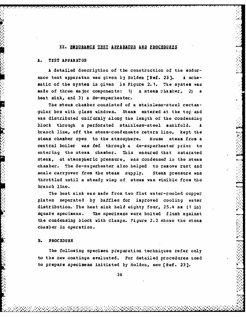
A. TEST APPARATUS
A detailed description of the construction of the endur-
ance test apparatus was given by Holden [Ref. 23]. A sche-matic of the system is given im Figure 2. 1. The systeu was
made of three major components: I) a steam zhamber, 2) a
heat sink, and 3) a de-superheater.
The steam chamber consisted of a stainless-steel rectan-gular box with glass windows. Steam entered at the top and
was distributed uniformly along the length of the condensing
block through a perforated stainless-steel manifold. A
branch line, off the steam-condensate return line, kept the
steam chamber open to the atmosphere. House steam from a
central boiler was fed through a de-superheater prior toentering the steam chamber. This ensured that saturated
steam, at atmospheric pressure, was condensed in the steam
chamber. The de-superheater also helped to remove rust and
scale carryover from the steam supply. Steam pressure was
throttled until a steady wisp of steam was visible from the
branch line.
The heat sink was made from two flat water-cooled copper
plates separated by baffles for improved cooling waterdistribution. The heat sink held eighty four, 25.4 mm (1 in)
square specimens. The specimens were bolted flush against
the condensing block with clamps. Figure 2.2 shows the steamchamber in operation.
B. PROCEDURE
The following specimen preparation techniques refer only
to the new coatings evaluated. For detailed procedures used
to prepare specimens initiated ly Holden, see [Ref. 23].
36
• "".""' .' ,"." . . . "' .'' . .*d . . . , ."".....* . *t ... , -.- , .', .', i, . " " - , - -i ' i

COOLANT ICOO LANTSTEANVNERDESUPERHEATER
CONDENSATE
0.45
Figure 2. 1 Endurance Test Apparatus.
37

I00
4 J(U'-4
'4 GD0~C -.
0
L.aGD.0U0.0C-)
*
00)
C',
(N -
38
- . . -
C .SLP*,' . :.~ A -. K - -- * ... .. ~. -. 4,-.. . 4 . 4 . . 4 . . 4 4 . . 4 4 -.-A 5 AC ~ *
1. Substrate Prearation
The following metals were used for specimen subs-
trates: 1) Oxygen-free high-ccnductivity (OFHC) copper, 2)90-10 copper-nickel, and 3) titanium. The copper and tita-nium specimens were 0.76 mm (0.03 in) thick. The 90-10 CuNi
specimens were 1.52 mm (0.06 in) thick. All specimens were
sheared into 25.4 mm (1.0 in) squares with edges sanded
smooth.
Three surface roughnesses were evaluated for theireffect on coating adhesion. These included: 1) number 40-glass-grit blast at a gage pressure of 20 psi, 2) number 220L
A10 -grit blast at a gage pressure of 40 psi, and 3)
industrial-size glass-bead blast at a gage pressure of
100 psi. The average RMS height for each surface roughness
was determined by means of a surface profilometer.
All specimens were cleaned for ten minutes in anultrasonic bath of ethanol. The specimens were handled with
tongs and remained untouched by human hands thereafter.
Specimens were sent to NRL, Washington, D. C., and coatingswere applied directly with no further substrate preparation.
Specimens sent out for commercial coatings had variations inroughness and handling procedures dictated by the manufac-
turer. These were considered proprietary by the manufac-
turer. Most industries use a grit blast followed by adegreasing procedure for substrate preparation.
+ ~2- ZPh~o aphi~c a4d UN Injesti_qationP-o-
Visual observations of dropwise condensation on the
specimens were conducted daily and photographs were takenevery 500 hours. Micrographs were taken of selected speci-mens with a scanning electron ticroscope (SEM). Since the
polymer coatings were nct electrically conductive, a shad-
owing technique was used to obtain the SEM micrographs. A
39
... , ... . . . . 4 . . ... . ...'.. - ,. ... - .

thin layer of 100% Fure gold was vacuum deposited for this
purpose using an Ernest Fullam Vacuum Evaporator. Based on
the volume of 203 jam (0.008 in) diameter gold wire used, and
the vacuum chamber surface area, the thickness of the depos-
ited gold layer was approximately 15 Angstroms.
3. Rhasicll Propre_ Tests
Two standard tests were performed which provided a
relative indication of a coating's adhesive and hardness
properties. A tape test for adhesion and a pencil test for
hardness were used following ASTM specifications L[Refs. 37,38]. Hardness testing was limited because of
surface roughness. The standard test calls for mirror-smooth
substrate surfaces; however, 220 grit blasted specimens were
used for some coatings. Because of the limited availability
of specimens, test results were assumed to be representative
of the specimens. A large number of tests would be required
to obtain statistically valid results.
Coating thickness was determined using several
methods. Coatings with thicknesses greater than 10 jim were
measured with a aicrcmeter. The thickness of the NRL fluo-
roepoxies and fluoroacrylics were determined by weighing the
specimens before and after coating application. A specific
gravity of 1.6, determined experimentally by Dr. James
Griffith at NRL, was used in the calculation of the thick-
ness. A knife-edge scale was used with an accuracy of
± 0.0001 g. Verification of coating thicknesses from SEH
photos was conducted whenever pcssible.
C. POL EZE COATINGS EVALUATED
Ten polymer coatings were evaluated for their ability to
promote and sustain dropwise condensation of steam at atmos-
pheric pressure. Five of the coatings were on specimens
40
• .p

7- "7
initiated by Holden [Ref. 23]. The remaining five were
modified versions of the coatings tested by Holden. The
intent of the modifications was to improve coating
dur ability.
Since the endurance test was designed to be harsh, it is
important to note that none of the coatings were designed
specifically for this purpose. Therefore, none of the
results or qualitative assessments should be construed as
critical statements of a particular coating's ability to
perform in its intended environment. The following coatings
were evaluated:
1. WRL 111uroepo32
Two variations of the NRL fluoroepoxy series were
evaluated. These included the C-6 and "Mixed" fluoroepoxies.
Both coatings were developed and applied by Dr. James
Griffith at the Naval Research Laboratory. Fluoroepoxy is
composed of two parts, a resin and a curing agent, mixed in
a four-to-one weight ratio. The general formula for the
resin is given in Figure 2.3.
c cr_)
Figure 2.3 General Formula for NRL Fluoroepoxy.
Fluoroepoxies are named in terms of the value of
"n", the number of carbon atoms in the perfluorinated,
straight-chained, "dangling" group present on the number
five pcsition of the central benzene ring. For the C-6 fluo-
roepoxy, "n" equals six. Mixed fluoroepoxy is made of a
combination of chains with "n" varying from five to eleven.
-
ri-
longer dangling groups should make the polymer more hydro-
phobic. The curing agent was "c-o" ethylene diamine. The
system was made compatible by dissolving both parts in
methyl-ethyl ketone. The coatings were applied to the speci-mens with an artist brush. Polymerization occurs after
2 application, producing a thermosetting polymer.
Four specimens coated with NEL C-6 fluoroepoxy ontitanium, copper, and 90-10 CuNi substrates were evaluated.Holden [Ref. 23] obtained greater than 4000 hours of drop-vise condensation on the specimens. All four substrates were
prepared using a size 40 glass-Lead grit blast. The dropwiseguality was classified as fair to good by Holden. He also
noted that the copper and CuNi substrates were darkened from
sub-coating corrosion.
In this thesis, fourteen specimens coated with NRLMixed fluoroepoxy were evaluated. This coating was clearand glassy in appearance. All three surface roaghnesses andsubstrate materials were used. Half of the specimens were
coated with an ultra-thin "wash" primer (MIL-P-15328D)before the fluoroepoxy was aplied. The wash primer wasapplied in an attempt to prevent subcoating corrosion.
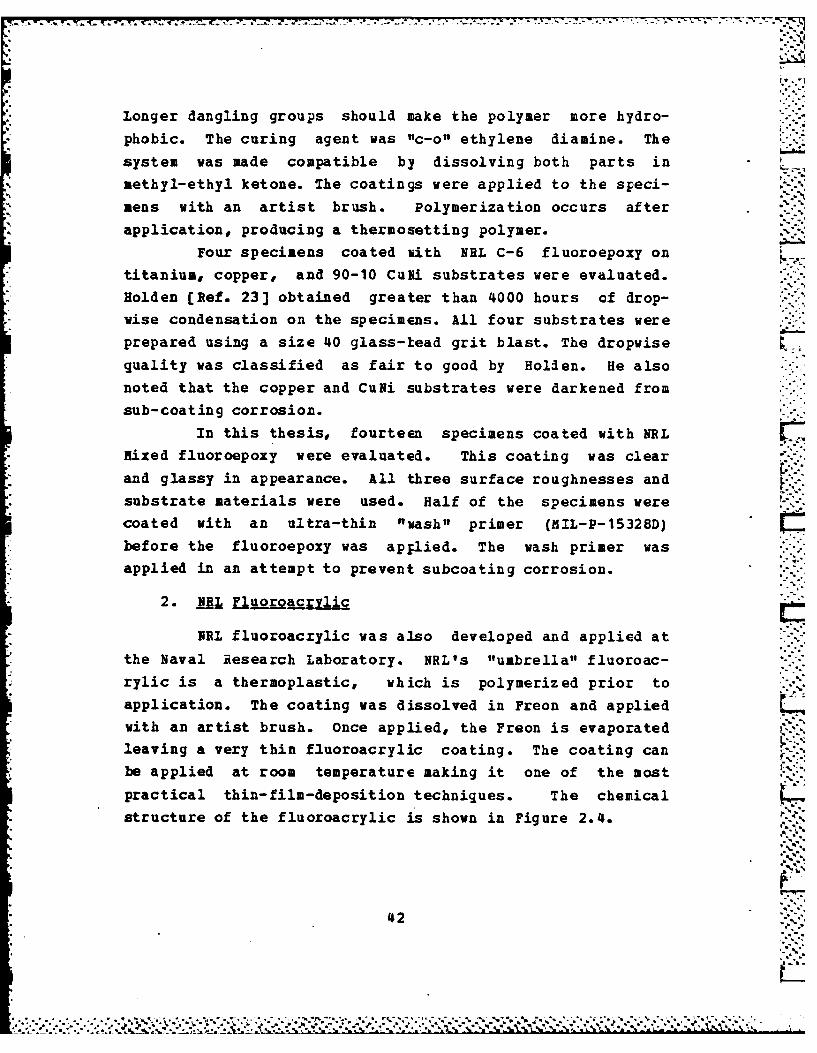
2. _RI, E_oroac rlic
REL fluoroacrylic was also developed and applied atthe Naval Research Laboratory. NRL's "umbrella" fluoroac-
rylic is a thermoplastic, which is polymerized prior to
application. The coating was dissolved in Freon and appliedwith an artist brush. Once applied, the Freon is evaporatedleaving a very thin fluoroacrylic coating. The coating can
be applied at room temperature making it one of the most
practical thin-film-deposition techniques. The chemicalstructure of the fluoroacrylic is shown in Figure 2.4.
42-".-.."-,S..
422
" L ,o ," . ,, ..","o".,",", ,'. . " ," , , % . %Z '_ _ .'L' ',% ." . ._. % .. V ..

F r
-- ".. "'
CH OC COC,115-, ,
3 3
Figure 2.4 NRL Fluoroacrylic.
Six specimens coated with the umbrella fluoroacrylic
were evaluated. Three of the specimens, which had rough
copper, CuNi, and titanium substrates, were continued from
Holden's work. Approximately 2,500 hours were previously
obtained with good quality dropiise condensation. The copperspecimen had a dark oxide layer. The remaining three speci-
mens had a vacuum-deposited gold layer beneath the coating.
Glass-bead roughened titanium and copper substrates wereused in addition to a mirror-smooth copper substrate. The
gold "flash" was used as a corrcsion inhibiter. Three addi-tional gold-flashed specimens were evaluated without polymercoatings for comparison. A crosslinked version of the fluo-
roacrylic was also evaluated. This was developed and appliedby the same methods used for the umbrella fluoroacrylic with
the addition of a crosslinking agent. Fourteen specimenswere tested in the endurance rig. Several specimens wereused for physical proFerty tests. Half of the specimens hadthe wash primer subcoating which was used with the
fluoroepoxies.
3. Payllne
Parylene is the generic name for a thermoplastic
polymer series develojed by Union Carbide Corporation. The
two coatings tested from this series were Parylene-N and
Parylene-D. Parylene-N is the basic member of the series,chemically known as roly-para-xylylene, shown in Figure 2.5.
433 "..'.

C1 i2 c'2
Figure 2.5 Chemical Formula for Parylene-N.
C1""f C1 .-
CJ2 Qt2
C.
Figure 2.6 Chemical Formula for Parylene-D.
Earylene-D contains t'io chlorine atoms on the
central benzene ring as shown in Figure 2.6. The coating is
applied by condensing the vaforized constituents on the
substrate in a vacuum. A glow-discharge process is sometimesused to activate the substrate for improved coating adhe-
sion. Polymerization takes place on the surface providing an
ultra-thin, uniform film.
.he parylene coatings were applied by Lawrence
Livermore National Laboratory which is licensed by Union
Carbide. Parylene-N specimens, as tested by Holden
[Ref. 23], gave disappointing results. This was primarily
because of the lack of substrate preparation prior to
coating. Coating thicknesses of 0.5 micrometers and .L
1.0 micrometer were evaluated. In this thesis, four
Parylene-N coated specimens were evaluated to verify -::-Holden's results. These specimens were from the same batch
as Holden's.
44
- -. - - - - -.... .. <.. . . *. -. * *. * *- -~. - a V * t A t#a± . ._ _ _ _ _ _ _ __ _ _ _ _ _ _ _ _ _ _ _

. . . . . . . . . . . . . . . . . . ,
Sixteen specimens coated with Parylene-D were also
evaluated. Coatings were applied on smooth (600 grit) and
rough (glass bead) substrates Erepared by Holden. Both 0.5
and 1.0 micrometer thick coatings were tested.
4. No-Stik
No-Stik is a thermally-conductive coating developed
by Plasma Coatings Incorporated. The coating process is
proprietary information. The coating is applied by a
thermal or plasma spray technique. Basically, No-Stik is a
fluoropolymer coating loaded with metal during the applica- ,
,- tion process.
The No-Stik(Cu) coating tested by Holden [Ref. 23]
. had copper as the base metal. Endurance testing was
continued for these specimens, uhich had previously obtained
4,000 hours of good to excellent dropwise condensation.
Holden's heat transfer results showed that the coating was
too thick (80 pm) to give any heat-transfer enhancement. Two
additional No-Stik coatings were therefore evaluated which
had aluminum and nickel-chromiui base metals. Attempts were
also made to have the coating applied thinner.
5 Z_ 3 "-'333
Emralon-333 is a one-cosponent blend of fluorocarbon
lubricants in an organic resin binder, produced by cheson
Colloids Company. The Emralon-333 was sprayed on using anexternal atomizing gun. Three specimens were evaluated in rcontinuation of Holden's work. Greater than 4,000 hours were
obtained previously with fair to good dropwise quality.
Holden [Ref. 23] noted that the resin binder was slowly
eroding away.
45
,' .... :• ".' ".21
,, , , - O , , - . C , - -,**** * -,* % ** **-, , o - " -. ,, .- o , , . - , ", * % *,,-,-_ , . "".- , ,°*j..' .¢ '&'_ ', .W % C'_ V .' .':'%. , . . _.,..:. ... .. . .. . .. . _ ... ; A .-:..- -.-.- .

III. HI&hIZ!UNSFZA ILE12lIMNTS
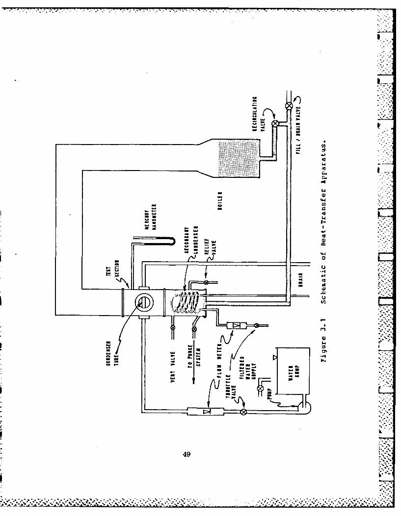
A. APPARATUS
A detailed description of the apparatus used f or heat-
transfer measurements was given by Poole [Ref. 39] and
Georgiadis [Ref. 41]. A schematic of the system is shown in
Figure 3.1. only a brief description of the apparatus is
presented in this thesis.
A 0.305 a (12 in) diameter glass boiler, using ten
4000-watt immersion heaters, generated steam from distilled
water. The steam then flowed through a reducer into an insu-
lated vertical section 2.44 m (8 ft) long. After passing
through a 180 degree bend, the steam flowed downward through
*a 1.52 m (5 ft) vertical section and entered a stainless-
steel test section. Figure 3.2 shows a schematic of the test
section with the tube mounted horizontally. A glass view
port was installed to allow observation of the condensation -
process. A secondary coil condenser was used to condense any
remaining steam. All condensate was returned to the boiler
by gravity flow. Vapor velocities past the test tube of up
to 8.0 in/s (26.2 ft/a) could be obtained when condensing at
a pressure of 0.012 ?lPa (1.62 psia) .
Two centrifugal pumps in series provided the cooling
water flow for the tubes. A throttle valve was used to varythe flow from zero to a maximum of 0.55 liters/s(8.8 gal/mmn). The condensing pressure was controlled by -
throttling the flow of tap water through the secondary
condenser.
A vacuum pump was operated continuously during the
experiment to ensure that the non-condensing gas concentra-
*tion was virtually zero. A 400 liter (106 gal) tank, used
46
aoo. *:.:*~~:.:~.: _____ -a- *° *

to provide a positive suction head for the cooling-water
pumps, was also used to condense any steam withdrawn by the
vacuum suction line in order to prevent moisture buildup in
the vacuum pump. This system is shown in Figure 3.3.
A silicon-controlled rectifier was used to regulate
power to the heaters. This provided an accurate measure of
the power being consumed. A mercury-in-glass manometer was
used to measure the test section condensing pressure.Since the coolant temperature rise (which was from 0.5
to 9 K) was the most important measurement in this experi-ment, two independent means tc measure it were used: two
quartz-crystal thermometers and a ten-junction, series-
connected, copper-constantan tbermopile. Proper insulation
and adequate immersion depths were provided for all probes.
7he quartz thermometers had a resolution of 0.0001 K, but,calibrating against a platinum-resistance thermometer, the
measurements were found to be accurate to within ± 0.03 K.The thermopile had a resolution of 0.003 K. During all data
zuns, Lhe coolant temperature rise measured by the quartz
thermometers and the thermopile agreed to within ± C.03 K.Two type-T thermocouples were used to measure the steam
temperature for the test secticn. A calibrated rotameterwas used to measure the cooling-water flow rate.
Raw data were recorded on disk by a Hewlett Packard
9826A computer interfaced with a Hewlett Packard 3497A DataAcquisition System. The rotameter and manometer readings
were the only ones which had tc be entered manually at the
keyboard.
Spiral inserts were used to enhance the inside heat-tr-ansfer coefficient for the tutes tested. This was neces-sary because the insllt- heat-tranzfer roist.c. ... z,the governing t1Iermal resistance during dropwise
* condensation.
47'.'
* . ..*. *- . * - - . . - - - . - * * - i.. ,* ** .-.* .- "

A small error in determining the inside heat-transfer
coefficient can give large errors when inferring the outside
heat-transfer coefficient froi the overall heat-transfer
coefficient.
The spiral insert consisted of a 6.4 mm diameter
stainless-steel rod with a copper wire wrapped and solderedaround it. The diameter and pitch of the wrapped wire was
3.2 mm and 34 am, respectively. The wire was machined togive a clearance of 0.5 mm between the outer wire diameter
and the tube inside wall. Although ASTH standard sized tubesp were used, the inside diameters varied for different tube
materials. Therefore, three different inserts were reguired
which had minor variations in pitch (± 3 mm) and outside
diameter (+ 0.7 mm).
B. TUBES TESTED
1. Plain Tubes
Prior to testing dropwise-coated tubes, data for
plain tubes with filmwise condensation were obtained. Thesedata were taken for two reasons. First, the data provided a
basis for determining the enhancement obtained from tubes
promoting dropwise condensation. The enhancement ratio wasdefined as the ratio of the drcpwise heat-transfer coeffi-
cient to the filwise heat-transfer coefficient. The values
of the heat-transfer coefficients determined at a heat flux
of 0.35 MW/M 2 were chosen for ccmparison purposes. Second,
the filuwise data were used in a Modified Wilson Plot data-
reduction program to obtain the inside heat-transfer coeffi-
cient.
Four tubes were used for filmwise data. These weremachined from OFHC copper, 6061-T6 aluminum, 90-10 CuNi, and
ASTM type 304 stainless steel. All of the tubes were
228.6 mm (9 in) long with a 133.4 am (5.25 in) condensing
length.
48
. .. .. .
.°
S
I
ps~)
.4- -a4.) m S-a.4 . -m ~. .4
0-J (12
0-. 4J
'V* 1.4* 'V
C..
.4
1.4m-a . 0I-a 44.4
.4 . =-a -
- a-- -a 'V= ~4.) ~ E-e-'.4
44
-aa"
______________ 0
U
'V
w_ U
cj~
0~
wLI0
mm IL,OhS-
--a ...a a.- m
I
a.' '~.
49
I,
Sb ~'% ~ . -. C'.. * . .. .. . . -

S. *~*...
I
p
-h a
~1 :$-: \\ V 0U2
;\~~j~ ~I ~- '.~ .~ p
,-' '-K4.'S.dQD
'A U'j a
I -
a0
.9.49.- .4.1
U
24
.4.19-, 1 U'
0-~ .
E4
4.4'.9 0
U' I U)
4.I-. 0U' .4.1
I ">i'K~~~ w
-7.. -
I ~
a'
"-4
.9...:
50
* . . . . ~ **~' * . .
...............................

I.-C
WU
E4
II~I0
a--
cr-p..- CL
CL.

The outside diameter for the tube condensing section was
14.22 mm (0.560 in). The tube inlet end length was 60.33 mm
(2.375 in) with a 19.05 mm (0.750 in) outside diameter. The
tube outlet end length was 34.93 mm (1.375 in) with a
15.88 mm (0.625 in) outside diameter. Although standard size
tubes were used, the inside diameters for the 90-10 CuNi and
304 stainless-steel tubes were found to be slightly larger
than the copper and aluminum tules. The inside diameter for
the copper and aluminum tubes were measured to be 12.70 mm
(0.500 in). Inside diameters of 13.21 mm (0.520 in) for the
90-10 CuNi tube and 13.36 mm (C.526 in) for the stainless-
steel tube were measured.
2. Polymer-Coated Tubes
A second set of tubes was machined to the same spec-
ifications used for the plain tubes. These tubes were then
cleaned with a soluticn of sodium hydroxide and ethanol. The
tubes were rinsed with tap water and dried, and were then
coated with a wash primer and with NEL fluoroacrylic. The
NRL fluoroacrylic coating was applied by dipping the tubes
in a solution of fluoroacrylic dissolved in Freon. The Freon
was evaporated, leaving a thim fluoroacrylic coating. The
surface roughness of the tubes was considered "smooth"
because the coatings were applied on "as machined" surfaces.
These tubes are also referred tc as "thin-walled" tubes with
measured wall thicknesses of 0.762 mm (0.03 in).
Five "thick-walled" tutes were machined and coated
with NRL fluoroacrylic. All tube dimensions were the same
as for the thin-walled tubes, with the exception of the
condensing section outside diameter, which was 19.05 mm
(0.750 in). Three of these tubes, one copper, one aluminum,
and one stainless steel, were grit blasted with size forty
glass grit at a gage pressure of 20 psi. Cleaning and
coating procedures were the same as for the thin-walled
tubes with the wash primer omitted.
52
1 ~: ~ -. . * ~ * ** .. .... .
The remaining two thick-walled tubes were coated
with wash primer and NRL fluoroacrylic. One of the tubes was
grit blasted with a number 220 grit at a gage pressure of p
80 psi, and the other had a knurled roughness which was
machined using a standard-fine-pitch knurling tool on a
lathe.
Two as-machined, thick-walled copper tubes were
coated with Parylene-D at lawrence Livermore National
laboratory. The coatings were vacuum deposited in the same
manner as the endurance specimens were coated. One tube was
coated with a 1.0 )im thickness and the other with a 0.5 2m
thickness.
A thick-walled copper tube was coated with
Zmralon-333 by Acheson Colloids Company. Surface preparation
was determined by the manufacturer. Two additional thick-
walled copper tubes were coated with No-Stik coatings by
Plasma Coatings, Inc.. One was coated with an aluminum based
fluoropolymer (No-Stik (Al)) and the other with a nickel-
chromium based fluoropolymer (N4D-Stik (NiCr)). Surface prep-
aration was determined by the manufacturer. When the coated
tubes were received, they were slightly warped and disco-
lored on the inside, indicating that they were exposed to
high temperatures during the coating procedure.
3. Silve r-Electroplated Tukes
Two thin-walled tubes were electroplated with silver
by a local merchant. One OFBC-copper tube and one 90-10
CuNi tube were plated, both cf which had smooth polished
surfaces. The tubes were plated for one hour in a silver-
cyanide electroplating bath.
53
'*-*..
. . . . . . ..

-X-. .. W.
C. EXPERIMENTAL PROCEDURE
1. Non-Condensing Gas Problem
Since the presence of non-condensing gases can
result in significant errors in the condensing coefficient,
considerable attention was given to avoid this problem. As
also stated by Georgiadis [Ref. 41], the test apparatus was
extremely leak-tight. While he reported a leak rate less
than 2 mmHg in a 24-hr period, a leak test performed (at a
pressure of 85 mmHg) during this work revealed a leak rate
less than 1 mmHg in six days. In addition to this remark-
ably leak-tight test apparatus, the use of continuouspurging (as discussed earlier) resulted in virtually no
non-condensing gases being present. The computed non-
condensing gas concentrations were less than ± 0.5 % (i.e.,
zero to within the accuracy cf temperature and pressure
measurements).
2. Mixing Chamber Calibration
A mixing chamber (see Figure 3.2) was used to obtain
a meaningful mixing-cup temperature at the coolant outlet.
Insulation was used to reduce errors in the calibration from
heat transfer with the surroundings. A calibration was
required to account for the temperature rise resulting from
viscous dissipation Suring the aixing process. The coolant
temperature rise was measured for various water velocities
with the system at room temperature and pressure. A calibra-
tion line was plotted for each tube type and insert combina-
tion. During condensation data runs, the coolantL%temperature rise was corrected by subtracting the tempera-
ture rise determined from the mixing chamber calibration.
Mixing chamber calibration results are plotted in Figure 3.4for the copper, aluminum, stainless steel, and 90-10 CuNi
tubes.
54
• ." .. * - .. .~ . ..- % ".% %,,..-.. . ,. . % % .'% . - . .% ° . ° . , °o. " . % % - ° .o% % % -%., ., °,%

3. Data Collection Procedures :,-
Perfect filuwise condensation was required when
taking data for the plain tubes. The slightest amount of
contamination caused scattered Fatches of dropwise condensa-
tion. These dropwise patches gave significant increases inthe coolant temperature rise which would give erroneous
results in data reduction. The tubes had to be thoroughly
degreased to ensure good wettakility. A solution of 50 -
sodium hyroxide and ethanol was used, in equal weight
proportions, for tube cleaning. A black oxide layer was
formed on the copper and CuNi tubes by brushing the surface
with the solution and steaming the tubes over a pot of
boiling water. This oxide layer was necessary because copper
is very reactive with the environment and readily adsorbs
contaminants which tend to prcmote dropwise condensation.
The oxide layer was extremely thin with negligible heat-
transfer resistance, see Georgiadis [Ref. 41]. '
Four complete data runs were made for each of theplain tubes. Runs were made cn different days after tube
removal and reinstallation to ensure repeatability of thedata. Each data run consisted of eighteen data sets. Data
sets were taken using the following sequence of flowmeter
readings (percent full-scale): 60-50-45-35-30-25-20-40-60.
Two sets of readings were taken for each flowrate. Perfect
filmwise condensation was observed throughout each data run.
Test section condensing pressure was maintained at 85 mmHg
(1.64 psia). Vapor velocity was maintained at 1.0 a/s.
The following flowmeter sequence (percent full-
scale) was used for tubes promoting dropwise condensation: i-.80-70-60-45-35-26-20-55-80. All dropwise data runs were
conducted at a condensing pressure of 85 mmHg with a 2.0 m/svapor velocity.
55
:%%-'..12P., .. .... ., *.., ., ... .. ..,. . , ., , . , .. . .*%*. '- * ",- "' * * " " l"""- "o- o° " ,°" % . . o ,o
"

7. I . -ft..
L 4'
0 0
E. C) 4'
N. N00
INI A
-P4
Ln ~ N00 01
CLOU.N 1-0110
561

c.J .l . .:,;: : .- j-: '.'::- .
- -.- - .--.-- : . - ---.---- -; n, :_ _ = ._ - - * . . -
At least two runs were conducted on different days for eachtube. Data runs at atmospheric pressure and 1.0 m/s vakorvelocity were taken for thick-walled tubes coated with NELfluoroacrylic and silver-electroplated thin-walled tubes.
The thick-walled copper tube, coated with wash primer andN1RL fluoroacrylic, was used tc obtain data for differentvapor velocities. Dropwise condensation runs were made at a P.pressure of 85 mmHg fcr the following vapor velocities: 2.0,
3.0, 4.0, and 6.0 mis. Vapor velocities were maintainedwithin 3 % of the desired values.
D. DATA REDUCTION
Two data reduction programs were used to process. raw
data. These were modified versions of the programs used byPoole [Ref. 39]. listings of these programs are given in
Appendices B and C.
1. ft~fi~ jil Plot PrS2ra I (jILSON3)
This program calculates the leading constant for the
Sieder-Tate eguation from the filmwise data. TheSieder-Tate correlation is used to determine the insidebeat-transfer coefficient, which is later used in the drop-
wise data reduction program.The Modified Wilson Plct method assumes a form of
correlation for both the outside heat-transfer coefficient
and the inside heat-transfer ccefficient, with two coeffi-cients to be found by iteration. In the past, Nusselt'sequation for film condensation cn horizontal tubes was used
for the the outside heat-transfer coefficient [Ref. 42].Ejuation 3.1 shows the form of the Nusselt equation gener-
ally used:
3 L/3 %' *
h~u = Nu k O g hfR_....,.,,
h~u- tp f q Do (eqn 3.1) 2
57 y~q
:l '1*" " **" ' ' " ' "' ' ' ' " " " "" " " " " " " . * * % %.. " "," % " . - -, " " . .

The Nusselt equation results in an value of
0.655 for zero-vapor-shear conditions, and the presence of
vapor shear generally results in a higher value, which must
be determined iteratively. Since this e.iuation is not valid
for high vapor-shear conditions, vapor shear must be held at
a low, constant value (corresponding to a velocity less than
1.0 m/s, for example).
to alleviate the deficiency of the Nusselt equation,
even with low vapor shear, a ccrrelation developed by Fujii
and Honda (Ref. 40] which accounts for the variation of the
outside heat-transfer coefficient with vapor velocity was
used during this investigation:
u!Re 0 " - O. 6 1/ (eqn 3.2)
This correlation was re-written to express h as a functionof heat flux and vapor velocity as shown in equation (3.3):
hfp1/ (1f l()38 3/9 1I/8 f
ho -( ) 0 v kfz r (eqn 3.3)
Here is a coefficient to le determined by iteration.
Equation 3.4 is the form of the Sieder-Tate eguation used to
determine the inside heat-transfer coefficient.
hbt - C1 Re0 . 8 r 1/ 3 (].1 - e Ci3
After substitution of equatione (3.3) and (3.4) into theequation for the overall heat-transfer resistance (equation
(3.5)), a linear equation used to jenerate the Wilson plot
58- *,.-,

is obtained (equation (3. 6))
+ + RWU0 AO fit At h0 A 0 (egn 3.5)
C1 aF (egn 3.6)
where,
-D. r
(egn 3.7)
and
- - RJ . r(egn 3.8)
The values of and are defined in eq~uations (3.3) andl* (3.4) , respectively.
The parameters X and Y are determined from the fluidproperty values and the heat flax measured during the film-wise data runs. Iteration between the Sieder-Tate coeffi-cient Ci and the F ujii coef ficient ,is continued untilconvergence within 0.1 % between two successive'iterations
occurs. The slope of the Nilson plot generated is theinverse of the desired Sieder-Tate coefficient. Sieder-Tate
coefficients were determined for each tube-insert configura-tion used for dropwise data.
2. Dr2PMise Data Reduction Pro~qrArn
This program was used tc determine the outside heat-*transfer coefficient from the dropwise data. The outside
59
* * . *'e

--7 7. ..77-*.,.-_7 --V_
I~ot-t~ns-~rI itir~z~ wir dot'r~i-le by iubtracting the~
in!;ide an-1 wall r-si.,;t.inc-:- t to:a t he over-Iill ii.t-transtnr
resistamnce as shown in u jaition (1.4 . Thz' overall. heit-
transtor cofficiont. wI~i- t.2:fQ tror. thE! moitired v'31110!
for the total hc'at tr~ini-t-r indi lol-roin-t npo'r.tiirl: dJif f'r'-
once (equation (3.9)):
11 O AA LMTD (egn 39)
The cond tc t ion res i stdinc~ o f t h" 1l) oIV!E C oat inog wa
incluledt in thq outsido~ttrn;~ resistinco'. The ifl53jde -
heat-trdnsfer coeffjcjp!nt wV L - doternino~ usin-j the
Sied.ir-rate n juit ion with tho :t.i')ro,)riate 1-ma ing coeff i-
ciernt detnrnino1 varl itr.
Appropriate crr,1.atiot~s worsi. u:;e'd to account for
flnid property variationz; with t.'imprrat lire. The fin orfect
of the t ube) on-1q, o'*i~iL t It-, con'1.!ns;inj s;ection, w -s
included in thle auialysis R'if . 39 J
60-

IV. RESULTS AND D~ISCSSO
KA. ENDURANCE TEST RESULTS
The quality of dropwise condensation on the test speci-
mens was classified as excellent, good, fair, or poor based
on visual observations. For excellent dropwise condensation,* the drops appear spherical in shape with contact angles
close to 90 degrees and the drops grow to no more than twoto three millimeters in diameter. Drop sweeping action
should be swift and vertical while maintaining good contact
angles. Drops which appear flat, irregular shaped, and grow
to greater than 4 am in diameter were characteristic of poordropwise condensation. A summary of the endurance testresults is provided in Table III.
During visual observations, it was noticed that thecopper condensing block promoted scattered dropwise conden-
sation. This occurred only after the block was cleaned
* -giving a shiny metal appearance. After investigation, it was
found that a volatile corrosion inhibiter (di-ethyl aminoethanol) was promoting dropwise condensation on the clean
condenser block. This chemical is injected into the house
boiler, which provided the steam supply for the endurancetest apparatus. After about one month, an oxide layer formed
on the condenser block producing filmwise condensation.
Based on the short-lived dropwise promotion of the corrosioninhibiter, the lower critical surface tensions of the fluo-ropolymers tested, and visual cbservations, it was decidedthat the chemical prcmoter had little effect on the quality
of dropwise condensation and coating endurance for the
coatings evaluated.
61
*1p
.- ***

I.°.
Two of the four C-6 fluoroepoxy specimens failed to
produce adequate dropwise condensation after about 6,500r. hours. The specimen with the Culi substrate was the first to
fail. The quality of dropwise condensation continuously
decreased with increased oxidation of the CuNi substrate.
Figure 4.1 shows the degradation of the dropvise quality for
this specimen. Excellent dropwise condensation on Parylene-D
is also shown for comparison. The other specimen which
failed had a titanium substrate. In this case, oxidationcould not be blamed for coating separation. Observation
under an optical microscope revealed tears in the remaining
portions of the coating. This was also observed for the CuNi
specimen. Since thermosetting Folymers tend to be brittle,
thermal stresses could be fracturing the coatings, causing
eventual failure by erosion.
Substrate oxidation tends to breakdown the mechan-
ical bond between the coating and the substrate. Two types
of substrate oxidaticn were observed to occur on the copper
and CuNi substrates. A "green" oxidation layer formed """bubbles in the coatings, as shown in Figure 4.1, eventually
separating the coatings from the substrate. A "black" oxida-
tion layer formed on some substrates. This layer didn't seem
to affect coating durability cr the quality of dropwise
condensation. No significant pattern was observed to explain
why some substrates had a green oxide layer and others a
black oxide layer. Whichever oxide layer formed first,
prevailed throughout the test fcr that substrate.
.wo C-6 fluoroepoxy coated specimens continued toproduce fair to good dropwise ccndensation. These are shown
in Figure 4.2. The titanium slecimens showed some wetting,indicating possible fractures existed in the coating which
exposed the substrate. It should be noted that the copperspecimen shown had a black oxide layer beneath the coating.
62
o' .-1

* ft * ."--. .-
The mixed fluoroepoxy coated specimens produced
slightly better dropwise ccndensation than the C-6
fluoroepoxy-coated specimens. At start up, all of the spec-
imens produced good dropwise condensation as shown in
Figures 4.3, 4.4, and 4.5. Maximum drop sizes appeared to be
larger for the 40-grit and glassbead-roughened surfaces.
These roughnesses had larger peak heights, which tend tohold up the drops, allowing them to grow larger before
departure. This indicates that the rougher surfaces would ..-
tend to reduce the dropwise heat-transfer coefficient.
However, this effect is very small as will be seen later. Nosignificant differences were ctserved between drop contact
angle and the different substrate roughnesses as shown in
Figures 4.5 and 4.6.
The wash primer used on some specimens significantly
reduced substrate oxidation. Figures 4.7 and 4.8 compare
CuNi specimens with and without the wash primer. In Figure4.7, it can be seen that the diopwise quality is poorer forthe specimen without the primer, indicating that the coating
is starting to fail. This shows definite evidence that the .,-.
reduction of substrate oxidation can significantly increasecoating endurance. It is still unclear as to whether the
wash primer improves the adherence of the coating to thesubstrate.
2. l1 Ej9. c
The two fluoroacrylic coated copper and titanium
specimens continued to promote good dropwise condensation in
excess of 9,000 hours. Some degradation of the dropwisequality was visible after approximately 7,000 hours.7his is shown in Figures 4.9 amd 4.10. The copper specimen
had an all-black oxide layer until approximately 7,000 hours
of continuous dropwise condensation. Then small green oxida-
tion spots appeared, which could explain the degradation in
63 *.
6 I"?

Figure 4.1 NRL C-6 Caffi/R 6 000 hrs. and Parylene-Don Cu~i/R 2,860 hrs..
Figure 41.2 NRL C-6 Ti/R 9,650 hrs. and on Cu/R 7,670 hrs..
64

Figure 4.3 NEL Mixed Pluoroep czy on CuNi/220 grit/wp/O hrs.and on CuNi/220 grit/O hrs..
Figure 41.4 NIL Niuxed Fluoroepcxy on CuNi/JO grit/wp/O hrs. .-
and on CuNi/40 grit/O hrs..
65

Figure 4.5 NRL Mixed Fluoroepcxy on Cu/glassbead/wp/O hirs.and on Cu/220 gri.t/O hrs..
Figure 4.6 NRL mixed Fluoroepcxy on Tj/40 grit/i ,120 hrs.and on Ti/glassbead/wp/lf1 0 hrb..
66

Figure 41.7 NRL Mixed Fluoroepcxy on CuNi/220 grit/vp/i, 120hrs and on CuNi/22V grit/i, 120 hrs..
Figure 41.8 NRL Mixed Fluoroepcxy on CuNi/40 grit/vp/350 hrs.and on CuNi/40 gril/3 50 hrs..
67

dropwise quality. The fluoroacrylic coated CuNi specimen was
* removed after 6,500 hours for SEM examination. This specimen
had some isolated areas of wetting which were visible prior
to removal. SEM observation IFigure 4.11) revealed that
cracks were present throughout the coating.
The three fluoroacrylic specimens, which had the
vacuum-deposited gold sublayer, continued to produce drop-
wise condensation in excess of 8,000 hours. As shown in
Figures 4. 12 and 4. 13, the dropwise quality was fair to
poor. This was unexpected since the fluoroacrylic coating
was applied in the same manner as were the specimens without
the gold sublayer. The gold suklayer practically eliminated
corrosion.
The results for the crosslinked-fluoroacrylic coated
specimens were disappointing. With the exception of the
glassbead-roughened specimens, the dropwise quality was good
to excellent during the first few hours of testing. Host ofthe glassbead-roughened specimens produced mixed film and
dropwise condensation, which became all film within the
first 20 hours of condensing steam. The specimens roughened
with a 220-grit blast were the next to fail followed by the
S0-grit blasted specimens. Figures 4.14 through 4.17 give a
comparison of selected crosslinked-fluroacrylic specimens
during the first hour of testing. Five out of six specimens
tested, which had 40-grit roughnesses, gave good dropwise
condensation several hundred hours longer than the specimens
with the other roughnesses. However, one 40-grit roughened
specimen, shown in Figure 4.15, produced filmwise condensa-
tion within the first hour.
These results indicate that the 40-grit roughnesses
gave the best mechanical interlocking between the coating P
and the substrate. SEN photos revealed that the specimens
with 40-grit roughnesses had relatively deep valleys and
sharp peaks compared to the glassbead and 220-grit
6e
F,-..
5. . . . . .- 4 * . * . * . . . . . . . . . . . . -"

roughnesses. In all cases, the coating conformed to the
roughness peaks. Tie glassbead roughness produced rounded
peaks and flat valleys with larger spacing between ridges.
Figures 4.18 and 4.19 show a ccmparison of the 40-grit and
glassbead roughnesses for crosslinked-fluoroacrylic coated
copper specimens.
Bo significant correlation could be made between
specimens with or without the wash primer and failure rate.
However, SEM observations showed that the wash primer was
exposed for specimens with the glassbead roughness. This canbe seen in Figure 4.20.
Dr. J. Griffith pointed out that the coating may
have failed because of the increase in the thermal expansion
coefficient of the coating from crosslinking. Hardness and
adhesion test results shown in Table III support this idea.
The crosslinked-fluroacrylic was much harder and gave better
adhesion than the umbrella fluoroacrylic.
Coating thickness was determined by weighing the
specimens before and after coating. The coatings proved to
be very thin ranging from 2-3 un. Three of the six specimens
evaluated for thickness had wash primer subcoatings. The
specimens with the wash primer showed only a 0.1-0.3/ m
increase in thickness compared to those without the wash
pri me r.
3. Parvlene
All but one of the Farylene-N specimens failed
within the first 24 hours of testing. The CuNi specimen gave
fair to good dropwise condensation for almost 4,000 hours.
SEM observations showed that the CuNi substrates had rough
surfaces in the as-received ccndition, which would have
given the greater coating durability. Significantly
different values were obtained for the adhesion testing of
9-
", .i- 69
.................". .. .

Figure 4.9 NEL Pluoroacrylic on Cu/B/6,4OO hirs.and on Ti/I/60400 hrs..
Figure 4.10 NRI Pluoroacrilic on Cu/R/7,690 hrs.and on Ti/R/7, 7 0 hrs..
70

00 *
Figure 1.11 NRL Pluoroacrylic on Cuui/E/6,5OO hrs. (SEMi xlOOO).
Figure 4.12 IRL F1loroacr~lic on ku-Cui/R, kA-Ti/R.
and Au-Cia/S 2,500 hrs..
71

a,4
Figure 4.13 NRL Fluoroacrylic on Au-Cu/i and A-Ti/i 6,540 hrs..
Figure 4.14 IlL Crosslinked Pluo oacrylic on Ti/eO grit -
Culi/220 grit/up/ hr..
* 72

Figure 4.15 EEL Crosslinked Fluoroacrylic on Cu/40 grit andCu/40 grit/vj/O hrs..
Figure 4.16 NRL Crosslinked Fluoroacrylic on CUNi/40 grit,* - Culi/4O grit/vp, and Culi/glassbeal/O hrs..
73

II
Figure 14.17 EEL Crosslinked Pluoroacrylic on Cu/220 grit/vp,Cu/glassbead/vp, and Ti/40 grit/vp/O hrs..
Figure 4.18 EEL Crosslinked fluoroacrylic on Cu/40 gritSEN (x2CO) .
714

NZ..
Figure 4.19 NEL Crosslinked Pluoroacrylic on Cu/glbd SEX (x200).
Figure 4.20 IlL Crosslinked Pluoroacrylic on Cu~i/glbd/vpSEE (xl O0O).
~ *~75

.I-. W. 4. 1;.
Parylene-N than those reported by Holden [Ref. 23].
Adhesion was found to be very poor with 90-100 7 of the
coating removed during tape testing. This was expected
because of the lack of surface preparation prior to coating
the specimens.
farylene-D gave significantly better results.
Specimens with smooth substrates generally failed in 100
hours or less. Water-filled bubbles separated the coatings
from the substrates as shown in Figure 4.21. Greater than
5,500 hours were obtained on specimens with rough subs-
trates. The quality of dropwise condensation was excellent F-_
for all the Parylene-D coated sEecimens, as shown in Figures
4.21 through 4.24. Figure 4.24 shows similar dropwise
quality between Parylene-D ccated CuNi and a vacuum-
deposited gold specimen.
No significant differences in endurance were
observed between the 0.5 and the 1.0 am thick coatings.
Adhesion tests showed significant improvements for
Parylene-D coatings compared tc Parylene-N. Only a small
increase in the Parylene-D coating hardness was found (see
Table III). SEM photos (Figures 4.25 - 4.28) show that the
Parylene-D coatings conformed to the surface roughness.
These photos also show that increased surface roughness
provides the mechanical-interlccking, between the coating
and the substrate, necessary fox adhesion.
It is important to note that the dropwise qualitywas better for Parylene-D than for the fluoropolymers
tested. Dr. J. Griffith noted that the inclusion of oxygen,
nitrogen, or other non-hydrophobic groups in the polymer
chains reduces the close-packing of hydrophobic groups,
therefore, reducing coating hydrophobicity. Since
Parylene-D is free of any inclusions separating carbon
atoms, very close-packed hydrophobic surfaces could be
obtained.
76
°.. . °, , *...S° .. o ... .° ... -.. ~. ..- . .-. -° . . . . % - .... . . .% .. ****-* %-.%. °°'
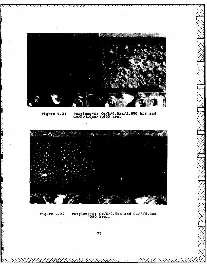
- ~ ~ ~ ~ ~ ~ ~ ~ ~ ~ ~ ~ ~ ~ ~ ~ ~ . .. - .. ... .. ...- - p.- *j- -. ,--- -
Figure 4.21 Pazylene-D: Cu/R/O.5uam/2,800 hrs andCu/3/1.Oua/l1,600 hrs.
Figure 4.22 Parylene-D: Cu/S/3.5Al and Cu/-"/O. 3pm4080 hrs..
77
7h

*Figure 4.23 Parylene-D: Ti/S/a.51u and Ti/R/O.5ps 3275 hrs..
IN
Figure 4.24 Parilene-D Cu~i/R/0.5aa/119050 hrs. andGola on Ti/R/f.,540 hrs..
78

Figure 4.25 Parylene-D on Ti/B/O.5 pam/O hrs. SEII (xlOOO).
Figure 4.26 Parylene-D on Cu/R/O.5 )15/O hrs. SE! (x200).
79

Figure 4.27 Parylene-D on TI/S/0.5 um/0 hrs. SEN (x200).
Figure 4.28 Parylene-D on CuNi/S/1.0 um/0 hrs. SEN (x200).
80

IIN 7 o1';
4. No-Stik
All No-Stik specimens ccntinued to produce excellent
dropwise condensation with virtually no coating deteriora-
* tion (see Figures 4.29 and 4.30). Greater than 11,000 hours
were obtained for No-Stik (Cu) specimens. Small green speckswere visible indicating that the infused copper base was
oxidizing. However, this didn't seem to affect the dropwise
quality or coating adhesion.
No-Stik(Al) and No-Stik(NiCr) specimens continued topromote excellent dropwise condensation in excess of 2,000 '
hours. Coating thicknesses were measured to be about 50 ps.
Although these coatings were thinner than the No-Stik(Cu)coating, they were still too thick to obtain significant
enhancement from dropwise conderzsation.
5. Earalon-333
The resin base continued to erode away from the
Emralon-333 coating, eventually exposing the substrate. Goodto excellent dropwise condensation prevailed until approxi-
mately 50 % of the substrate was visible through thecoating. Figure 4.31 show a brass specimen with the coatingbadly eroded. Other specimens shown in Figures 4.31 and 4.32show Emralon-333 coated specinens with excellent quality
dropwise condensation. Endurance lives in excess of 11,000
hours were obtained.
Since polymers are basically non-reactive, very
little change in steam-plant chemistry would occur from
eroded or washed away polymer coatings, especially sincevery small quantities (in weight and volume) of the polymersare present when the coatings are thin.
81. ..

.... ..... . . . . . . . . . . ..... .
Figure 4.29 Io-Stik(Cu) on Ti/7,670 hrs. and Ti/9,650 hrs..
Figure 4.30 Uo-Stik(SiiCr) and No-Stiic(A1) on Cuk~i at 780 hars..
82

40f.
77.
*Figure 4.31 Earalon-333 on Ti/6,400 hrs. and Brass/6,'I0O hrs..
Figure' 4.32 Emralon-333 on Ti/7670 hrsp Brass and Ti 9,65'0 hrs..
83

B. HEAT-TRANSFER RESULTS FOR PIAIN TUBES
Prior to processing filawise or dropwise condensation
data, appropriate values for the substrate thermal conduc-tivity and the inside heat-transfer coefficient must bedetermined. A sensitivity analysis demonstrating the impor-tance of selecting an accurate value for substrate thermalconductivity will be discussed first. Then the resultsobtained from the filmwise condensation data will bediscussed, which were used to cbtain appropriate values forthe Sieder-Tate coefficient.
1. Sensitvit of a euction on Substrate Thermal
Conduc tivity
Proper selection of sutstrate thermal conductivitywas essential in obtaining accurate values for the outsideheat-transfer coefficient. A search of several data sources,including the American Society of Metals [Ref. 43] andTouloukian [Ref. 44], showed that differences in reported
values of thermal conductivity of metals could be as much as10 %. A sensitivity analysis showed that a 10 % differencein substrate thermal conductivity made less than 3 % differ-ence in outside heat-transfer coefficients determined fromfilawise condensation data. Differences in the Sieder-Tatecoefficients, determined fron the Modified Wilscn Plotmethod, were also less than 3 5. However, significant errorscan result in determining drcpwise heat-transfer coeffi-cients for tubes with low thermal conductivities. This wasfound to be the case for the stainless-steel and 90-10 CuNitubes. For thick-walled, stainless-steel tubes, as much as a50 % reduction in the dropwise beat-transfer coefficient wasobtained, with a 10 1 increase in substrate thermal conduc-tivity (see Figure 4.38). For the thin-walled stainless-steel and 90-10 CuNi tubes, only a 10 % reduction in thedropvise heat-transfer coefficient was obtained.
84
... ,..........-.....'.v...'."4....4... . .- - . .* ""'-i ."-,. ". -"." a "- - " " " - ".-" --. - - ,4..'-.'.,-, _,.-_-,'i,

TABLE III
Endurance Test Results
Suoscrace/ Thic~ness Oropwise ouns ofCoating Surface Us Rardness Adhesion Performance Operation
C-6 Fluoroepox TI/U 6-2 Ha 51 Fair >11,000Cu/M 6-8 25 53 Fair/Good >8,950Cuffi/D 6-8 23 53 Fair/Poor 6,500
mixed TI..CoD 6-9 G6. 3 Good >2,500Fluoroepoxy Cu3.C,D 8-9 61H 51 Good >2,500
Cumi /a, C, D 8-9 61H 53 Good >2,500
FluaeroacryLic T/U 2-3 F 33 Good >9,000Cu/U 2-3 , 33 Good >9,000Cuf in 2-3 F 33 Good 6,500Cu-Au/V 2-3 F 31 Fair/Poor >8,000Cu-Au/A 2-3 F 33 Fair/Poor >8,000Ti-AU/U 2-3 F 33 Fair/loor >8,000
Cro-elgaked Till 2-3 4R 33 Fair <20Fluoroacrylic Ti/C 2-3 4R. 53 Good/Excel <1.,000
TI/U 2-3 4ff 53 Fair/Poor <20Co/i 2-3 41 53 Fair/Good <20Cu/C 2-3 4R 53 ood/Excel <I,0O0Cu/M 2-3 4R 53 Fair/Poor <20CuNt/3 2-3 4R1 53 fair/Good <20Cu&i/C 2-3 4R 53 Good/Excel <1,000C ML/D 2-3 W 53 fair/Poor <20
ParyLene-q Cu/A 0.5 3 13 Good <20Cu/A 1.0 3 13 Good <20Cuff/U 0.5 3 is Good (20Cut/M 1.0 B 13 Good <4,000
Parylene-0 Ci/A. 0.5 , 63 Excel >5,500Cu/A L.0 FM 4B E=xl <100Cu/M 0.5,1.0 HB 4B Excel >5,500CuM /A 0.5 EM 43 Excel >5,500Cufll/A 1.0 UB 4B Excel <100cum /a O.5,1.0 FM 48 Excel >5.500TI/A 0.5 UB 43 Excel >5,500TI/A 1.0 f 43 Excel 100Ti/D 0.5,L.0 M 41 Excel >5,500Ir/A O.5,1.0 FM 23 Excel <20Rt/ 0.5,L.0 U 4B Excel >5,500
o-Stk(Cu) CuTi/U 60 41 5B Excel >9,000CuMLI,?T/ 60 41 53 Excel 11,000
No-Stik(Al) CuTI, CuNt/U 50 51 53 Excel >2,100
Nl-stik(UICr) CUTICuiui 50 61 53 Excel >2,100 -
Eumralon-333 TL,3r/U 13 F 53 Good/Excel >11,000tr/U U F 53 Good <6,500TI/ 13 F 53 Good/Excel >11,000Cu1l 13 F 53 Fair/Good <5,500
Gold TIM/ 0.5 - - Excel >8,000
Note: Roughness Eardness AdhesionA- 600 grit C - 40 grit otet L mmt.." 'A-GOgitC40git 1softest 13 -least1 - 220 grit U - glass-bead 6R - hardest S1 - mostUr - unknown
85
%-. :.

*, . -, . -%q i . .". . _._, n ~ b. - - 2 % ,-E. -- ~ ' '- ,-"
*.
-*- ,. -_•.-., _ , , *. _o
The large dependance of the dropwise heat-transfer
coefficient on substrate thermal conductivity is a direct
result of inferring the outside heat-transfer coefficient
from the overall value coefficient. For low thermal conduc-
tivity substrates, the wall resistance can become dominating
when condensation occurs in the dropwise mode. Therefore, a
small error in the wall resistarce can give large errors in
the outside heat-transfer coefficient. This was the primary
reason for selecting thin-walled tubes to evaluate the
effect of constricticn resistance.
Table IV lists the selected values for substrate Lthermal conductivities used in the data reduction programs.
All of the values in Table IV were taken from [Ref. 44] with
the exception of the value for CuNi which was given by the
manufacturer. These values were based on an estimated
average wall temperature of 310 K. at 85 mmHg condensing
pressure.
TABLE IT
Substrate Thermal Conductivity used for Data Reduction
Material k (W/mOC)
0 HC Copper 385.0A0 61- I6 167.0CuNi 90-10 45.0SS Type 304 16.0
Sieder-Tate coefficients were determined for each of
the four tube-insert configurations tested. Average values
were determined based on the results of the four data runs
taken for each tube. Differences between the coefficients,
determined for any cne tube, were less than 3 %. Table V
gives a summary of the average Sieder-Tate coefficients
86
'CIL

obtained for each tube configuration. The values are tatu-
lated according to insert number and tube material. The 'Sieder-Tate coefficients shown were determined using theFujii-Honda equation (eqn. 3.3) and also using the Nusseltequation (eqn. 3.1) in the Modified Wilson method. A sample ,"
Wilson plot is shown in Figure 4.33. The Sieder-Tate coeffi-
cients determined using the Fujii-Honda equation predict an kinside heat-transfer coefficient 3-4 % higher than thevalues obtained using the NuEselt equation. Georgiadis
[Ref. 41] reported a value of 0.071 for the Sieder-Tatecoefficient obtained using the Nusselt equation for asimilar tube-insert combination.
TABLE "Sieder-Tate Coefficients used in Data Reduction
Tube Insert Ci CiMaterial Number (Fujii-Honda) (Nusselt)
Cu 1 0.0702 0.0675Al 1 0.0720 0.0684Cumi 2 0.0741 0.0716SS 3 0.0689 0.0666
Differences in the values obtained for the differenttube configurations can be attributed to differences in the
tube inside diameters, spiral-imsert pitch and diameter, andexperimental errors. As noted earlier, the copper and
aluminum tubes had the same insert and inside diameters. Thetwo Sieder-Tate coefficients cbtained for the copper and
aluminum tubes are in close agreement with each other(within 2.5 %).
In order to check data reduction procedures and theaccuracy of the measurements, the raw data were reprocessed
using the Sieder-Tate coefficients determined with the
• Fujii-Honda correlaticn (see Table V). Figure 4.34 shows asample plot for the reprocessed filmwise data obtained for
87
the copper tube. Good repeatability was demonstrated for all
four tubes with less than 3 % scattering of the data points.
A theoretical line strictly based on equation (3.1) is also
plotted in Figure 4.34 for comparison. This line represents
a zero vapor shear condition withcAu set equal to 0.655.
Figure 4.35 shows a comarison of the filmwise data
with the correlation of Fujii and Honda (equation (3.2)).
These data show good agreement with the Fujii and Honda
correlation. [Ref. 40].In order to determine the outside heat-transfer
coefficient from the dropwise data, the Sieder-Tate coeffi-
cients based on the Fujii-HoEda equation were used to
predict the inside heat-transfer resistance using equation" (3. 5).
C. BEAT-TRANSFER RESULTS FOR PCLYEER-COATED TUBES
A summary plot showing the enhancement obtained fromdropwise condensation on the pclymer coated tubes is given
in Figure 4.36. This plot is shown here because it will be
referred to throughout this discussion. The plot gives a
comparison of polymer coatings applied to thick-walled
copper tubes on which steam is condensing at a pressure of85 mm~g and a vapor velocity of 2.0 m/s. A plot for film-wise condensation on a copper tube using the same insert and VSieder-Tate coefficient is provided for comparison.
1. Zloroacrylic Coated Tutes
As shown in Figure 4.36, NRL fluoroacrylic gave the
largest enhancement of the outside heat-transfer coefficient
of all the polymer coatings tested. An enhancement ratio of6.5 was obtained. This agrees closely with Holden's
888.4"""
"'.-,. " -

w
r4 0
WN
to 0c
E 1-40
Lo 4 0
04ww
0. 1*oi
rq 0

-- ~.t. ....... . ~ ... *.. . ,. -. . .. . . . . . . . .
CYS
U)I
M IV 0
inIn
In~ 0
900

.. -7, -7 -X - P"
I IV
w 4
Iu 40~.0
0)W
F40
"U
91-6
v40. t~
~IOr
91.

A) 0 1E 1EE
EL 00 Li r. 0
z
w AL*a. 0 0)J.
a. N OA
* 1 4.40
~4M1 N ~
0 0 0 0 00 00r* ~ ~~ CD N ( I 1n
LS.
92E
w (D 4.
*.,* %~* . . . . .. .~. . . . . .
. . . . . . . . . . . . . . . . . . .. . ..4. .'
CD (D 11 m:x~.L. ~ * V . .. *)/ %l

results [Ref. 23] for a similar NRL fluoroacrylic coated
copper tube. The dropwise quality was good to excellent.
Coating thicknesses were estimated to be 2 to 3 micrometers,
based on the endurance test results (see Table III).
A comparison of the data obtained for the three
thick-walled tubes at vacuum ccnditions is shown in Figure
4.37. Dropwise quality was visually the same for all three
tubes. The tubes with aluminux and copper substrates gavebasically the same enhancement. However, the stainless-steel
tube gave significantly lower values for the dropwise heat-
transfer coefficient. The validity of the data obtained for
the stainless-steel tube is questionable, however, based on
the sensitivity analysis discussed earlier. For- the thick-
walled stainless-steel tube, the tube wall resistance is thegoverning resistance. Therefore, a small error in the wall
resistance can cause large errors in the dropwise heat-
transfer coefficient.
Data were also taken for thick-walled copper and
stainless steel tubes at atmospheric pressure. These results
are presented in Figure 4.38. A 15 % increase in the
enhancement ratio was obtained for the thick-walled copper
tube at atmospheric pressure compared to conditions atvacuum. Although drop sizes appeared to be bigger, sweeping
action was increased considerably. This was expected becauseof the higher condensing rate cbtained with the larger LATDat atmospheric conditions. Graham [Ref. 5] showed a similarpressure effect. The sensitivity of the thick-walled stain-less steel tube results to a 10 % change in substratethermal conductivity is also shown in Figure 4.38. This
demonstrates the importance in using thin-walled tubes when
considering the effect of substrate thermal conductivity ondropwise heat-transfer coefficients. Atmospheric data were
not taken for the thick-walled aluminum tube because coating
deterioration was observed on this tube after it had beenoperated for several runs under vacuum conditions.
93
"..r

The results for the four NRL fluoroacrylic coated,
thin-walled tubes are shown in figure 4.39. These data weretaken primarily to evaluate the effect of substrate thermal 5conductivity on the dropwise heat-transfer coefficient,
which will be discussed in more detail later. It should be
noted that enhancements were significantly lower than those
obtained from the thick-walled NRL fluoroacrylic coated
tubes. This was most likely due to the added thermal resis-
tance of the wash primer. Figure 4.40 shows that the drop-
wise quality was basically the same for each of the tubes.
The data runs were repeatable to within 5.0 % for all four
tubes. After several runs, some small localized deteriora-
tions were visible in the coatings. This was because the
tube surfaces were smooth giv.-ng poor coating adhesion. Withthe exception of the thick-walled aluminum tube, the tubes
which had rough surfaces showed no signs of deterioration inthe NEL fluoroacrylic coatings after an average of 20 hours
of testing.
The effect of the wash primer on the dropwise heat-transfer coefficient can readily be seen in Figure 4.41. Thetube without the wash primer gave an enhancement ratio of6.8, while the tubes with the wash primer gave on the
average an enhancement ratio of 3.5. This can only be
attributed to the added therial resistance of the wash
primer since both the primer and the coating were includedas part of the outside thermal resistance. As also shown in
Figure 4.41, substrate roughness has little effect on thedropwise heat-transfer coefficient. The differences chownfor the three tubes, which had the wash primer, could easily
be attributed to experimental errors or coating thickness
variations.
94
. . .~ . . . . .

AD-A154 743 ENDURANCE AND HEAT-TRRNSFER PERFORMANCE OF POLYMER 2/CORTINGS FOR THE PRONO..(U) NAVAL POSTGRADUATE SCHOOLMONTEREY CA D J LOONEY DEC 84 NPS-69-84-8e5
UNCLASSIFIED F/G 11/3 NL
EmmEEEhnsE]hhEIIIIIIIIIIIIIlEu"..IIIII

III1.0 We W
111"C" 0 L3.6 J M~IVA
111 I'1681 .211. 4~
MICROCOPY RESOLUTION TEST CHARTNATIONAL BUREAU OF STANDARDS-1963-A
. . .: 4.
"o
-..' . . - . ,,,S.. , t .,.. ,. . . ,.',v. , .' _ .-." . "' , .f. .. - '.- ' - ". . ' . ,. - -. - , . . ; ,-,. ,.

2. larlene-D Coated Tubes
The quality of the dropuise condensation on the two
Parylene-D coated tubes was classified as good. Enhancement
ratios of 3.3 and 2.0 were obtained for the 0.5 and the 1.0
micrometer thick coatings, respectively (see Figure 4.36).
Thicknesses of the coatings were determined by LawrenceLivermore National laboratory kased on the deposition rateused for coating the tubes. This shows the importance of
having ultra-thin coatings to cbtain suitable enhancements
from dropwise condensation. The thermal conductivity of
Parylene-D is about one third that of PTFE, which explains
why such low enhancements were obtained even though the
coatings were thinner than the NEL fluoroacrylic coatings.
Although the thermal conductivity of the NRL fluoroacrylic
coating has not been adequately measured, it is thought to
be close to that of MFE.
3. No _ti Coatd Iubes
The No-Stik(ll) coated tube gave little enhancement
in the outside heat-transfer coefficient (see Figure 4.36)
even though good to excellent dropwise conditions were
observed (see Figure 4.42). This was expected because of the
50 )im coating thickness. This was an improvement over the
results reported by Holden [Ref. 23] for the No-Stik(Cu)
coating. This shows that the insulating resistance of the
fluoropolymer used in the coating outweighs any benefitsfrom the thermally conductive lase metal. Even though the
No-Stik(Al) coating had a lower base metal thermal conduc-
tivity than No-Stik (Cu), it gave better heat-transfer
results because it was thinner.
95 .
pi.-

*00 IA
olw
E* 00* '-4 Q
a. >.l
02) ~r-4
0N Wr-
9 3 3
0 10
r4.44
'=F4
0 00Y D
P4
M *J'i
96.

u u a)E E Ifl
14Ad w
r4 w40. 0 ) wa
IL.> r4Ja
0 0E *04 cEw~
140
EA 0
414
10
0*M -ZfYM) H 0
U)90

r.4
z a.
Lr)
1310 04
E 4
E E
)l 0(D N -r4&
>*
ifD (D *r (T) 1
(X W/W-0 L
9841

in
E9-4
A1.4
.9.4
0 U
41 0tau,00Us
r-4
U~ 0
to0
04)
9941

L
i:11l1T1 I .4,
EE E L I.
0 0 (
m 43
* ,V4 0
tvE 0o
0-0
o L0£/ iU\o Q..44
6. 0'JLo0DL M 'U 0.
DH "L Iu/l L -N-'-"
c E (I N
0.
.0
in:'
opo
OD Q )m (Jr
100
• '., .*+." . s+- , ,. . .. * J "- "'-. ... .- ,. **. ".,,-. ,.'. .".. "..- ',. .,."- .*. :_ _. . . . . " -.. t- .' " .. ._ . :-' . . .

The No-Stik (MiCr) coated tube was not evaluated
since the coating thickness waE also measured to be 50 um
and, therefore, less enhancement would be expected. Since
the No-Stik coatings appear to be very durable and
corrosion-resistant, an effort to reduce the coating thick-
ness further is warranted.
The Emralon-333 coating produced good to excellent
dropvise condensation as shown in Figure 4.43. The coating
thickness was measured to be 13 jus (0.0005 in). The coating .
was still too thick to obtain any enhancement from dropwisecondensation. A 20 S reduction in the outside heat-transfercoefficient was obtained compared to that of filswise data(see Figure 4.36). The coating showed no signs of deterio-
ration throughout the data run. It should be noted that eventhough the No-Stik(Al) coating was four times thicker than
the Eralon-33, it gave better enhancement in the outside L
heat-transfer coefficient. This implies that a 5-10 us thick
coating having a dispersion of thermally conductive
particles might give good results. On the other hand, the j.
coating must be thick enough since the thicker coatings areusually more durable.
5. 1ie-Electroplated Tjl el
Coating thicknesses were approximately 10 pm for the
two silver-electroplated tubes. The silver-electroplatedsurfaces were bright and mirror smooth, and were were veryhydrophobic, promoting excellent dropvise condensation.
*" There was no visible difference in the dropwise qualitybetween the copper and CuNi tubes. This is shown in Figure4.44 with steam cond-ensing at a pressure of 85 mmHg.
Three complete data runs were conducted at a pres-sure of 85 mmHg for each tube. The data runs were made on
101
& ... "-. ' _. .- .. : - . *.. .& Az . .Y i' '- T r . , -. . ,-._o A.- -
,'.°
• r
different days with tube removal between runs. An average
enhancement ratio of 10 was obtained for both tubes as shownin Figure 4.45. Three complete data runs are shown for each
tube. On one occasion, a data run for the CuNi tube gavedropwise heat-transfer coefficients that were 30 S higher I
than the previous twc runs. Although the tubes remained
untouched during installation and handling, it was believed
that the increase was due to some unknown source of contami-nation. The water for the boiler was flushed and replaced
with clean distilled water. The tube surface was cleanedwith ethanol, rinsed with distilled water, and re-tested.
This time the data agreed with the data from the first tworuns. It should also be noted that the tubes remained
untarnished after a week of testing. The values obtained for
the dropwise heat-transfer coefficient are in good agreementwith the results O'Neill and Westwater [Ref. 21] for silver-
electroplated vertical flat plates.
Data runs were also conducted at atmospheric pres-
sure for both the copper and CuNi tubes. Heat fluxes up to3.0 II/m2 were obtained. The dropwise condensation observed
was far superior to that observed for any of the other coat-
ings tested. Drop sweeping rates were extremely fast,preventing drops from growing mcre than about 2 mm in diam-eter (based solely on visual observations). The results are
plotted in Figure 4. 46. Enhancement ratios were found to be "between 30-40 times that of filmwise condensation.
A large amount of scatter was evident in the dataobtained at atmospheric pressure. This was a result of thelarge uncertainties that exist when inferring the dropwise
* heat-transfer coefficient from the overall coefficient,particularly when the outside thermal resistance is very
• small. Uncertainty trends are discussed in more detail in
*"~Appendix A.
102
! %
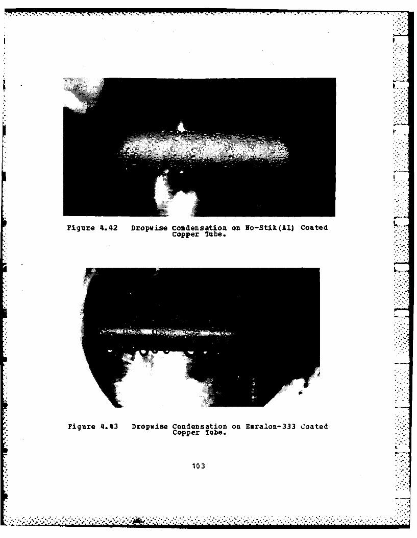
Figure 4.42 Dropvise Condensation on No-Stik(11) Coatedcopper lube.
Figure 4.43 Dropwise Condensation on Earalon-333 CoatedCopper 7ube.
103
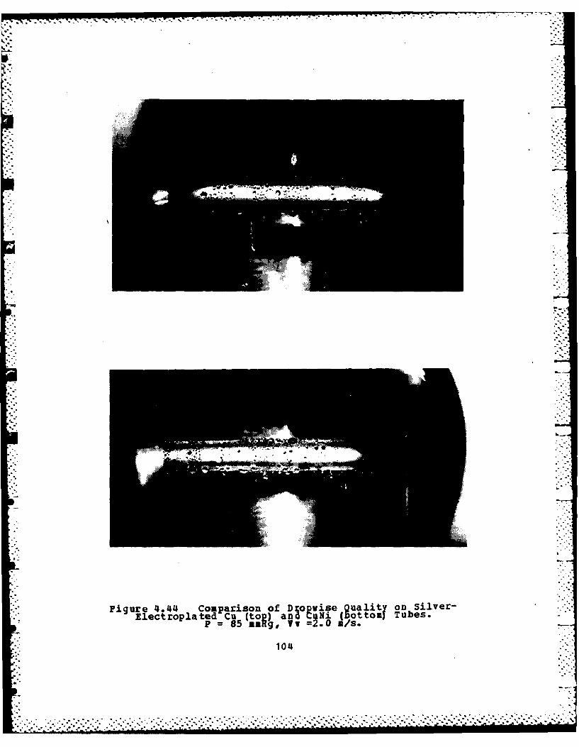
Figure 4.44 Comparison of Dxotvisega 0taitf on Silver-Electroplated =Cu(to 1) and u Ni (ot ton Tubes.
P ~ ~ ~ V asa oT 2.0 a/s.
104

.06 41 z 440
.00
*~ r4
'44
.04i Z *0~ S ;b
E E0E.t
00
(DON
E- EC004
U))0:44
0 0 0 0 0 0
LLi
1050
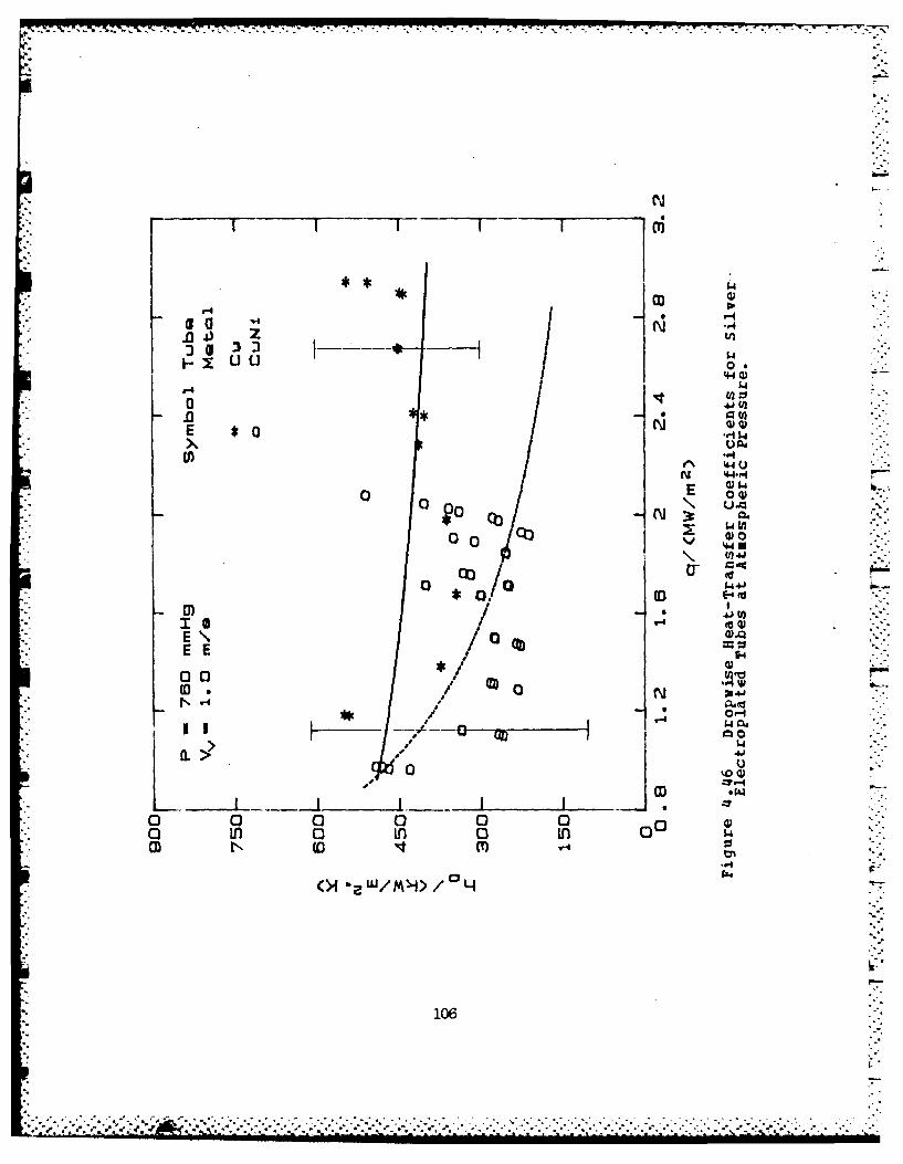
a -o
60 0 0
E 02
*0 0
-4'05.
00, a 4Jol ~E-4 (
II
E E
,i -pi N
.4 w4
a. > 0 41b
o 0 0 0 0 0 1o in 0 in 0 In 0 w
106

D. EFFECT OF SUBSTRA7E THERMAL CONDUCTIVITY ON THE DROPWISE
BEAT-TRANSFER COEFFICIENT
In addition to evaluating the coatings for dropwise
promotion, several important conclusions were made ccncernigthe thermal constriction resistance. In particular, the data
obtained from the silver-electroplated copper and CuNi tubes
(Figure 4.45) support the view of Rose [Ref. 12] that subs- .trate thermal conductivity has little effect on the dropwiseresults. The data shown in Figure 4.46 also support Rose's
view if the uncertainty of the data is considered.
The data obtained from the four thin-walled fluoroac-
rylic coated tubes (Figure 4.39) also support the view thatthe thermal constriction resistance effect is small, partic-
ularly when polymer coatings are concerned. The data for thealuminum and the CuNi tubes weze 20 % higher than the data
for the copper tube. The stainless-steel data agreed within
3 X of the copper data. Since the dropwise qualities wereessentiallly the same for the four tubes, the differencesare believed to be primarily due to variations in the
coating thickness. From a simFle heat-transfer resistance
analysis, assuming a coating with a 0.35 W/m-K thermalconductivity (PTFE), it can be shown that a 0.5 jim differ-ence in coating thickness can cause a 20 % difference in the
dropwise heat-transfer coefficient.
The data obtained from the thick-walled NRL fluoroac-
rylic coated tubes must be excluded because of the sensi-
tivity of the stainless-steel data on substrate thermal
conductivity, which was discussed earlier. In addition,variations in the coating thickness must Le considered.Because of the thinness of the NEL fluoroacrylic coatings,
accurate measuements of their thicknesses could not be made
with the facilities on hand.
107
V, '.
-;L " " •"" " " , " "' . ' , " " - .. ' . " • • . . .. . " ."° " " ' " ' • , • .

r i•
Another important note is that the tubes tested had very
thin walls (0.762 mm or 0.03 in). This would tend to show
the largest effect of the thermal constriction resistance as
noted by Hanneman [Ref. l4].
3. RFECT OF VAPOR VELOCITY 01 THE DROPEISE HEAT-TRANSFER
COEFFICIENT
The thick-walled copper tute, coated with wash primer
and N L fluoroacrylic, was used to evaluate the vajpor
velocity effect on the dropwise heat-transfer coefficient.
The results are shown in Figure 4.47 for four differentvapor velocities at the same ccndensing pressure. The datashow that the dropwise heat-transfer coefficient continu-
ously increases with increasing vapor velocity. However, the
increase in dropwise beat-transfer coefficient becomes less
with increasing vapor velocity. This can readily be seen in
Figure 4.48, which is a crossplot of the dropvise heat-
transfer coefficient versus vapcr velocity, for a 0.35 MW/ 2
heat flux. This trend agrees sith the results presented by 44Graham [Ref. 5].
P. AN ALTERNATIVE APPROACH TO IHE MODIFIED WILSON METHOD
The accuracy in determining the dropwise heat-transfer
coefficient, from an overall heat-transfer resistance anal-ysis, can be strongly dependent on the value of theSieder-Tate coefficient used tc predict the inside heat-
transfer resistance. During dropwise condensation, the
outside heat-transfer resistance is small and the inside
heat-transfer resistance can become the dominating resis-
tance. Therefore, a small error in determining the
Sieder-Tate coefficient can cause large errors in the drop-
wise heat-transfer coefficient.
108
4°
.4444
d- - '- "- " - " ." " ' € ."" ." , , . : - . - : . '"" " . .'""" ' ' ." " ' ' . . .. , . " : ,
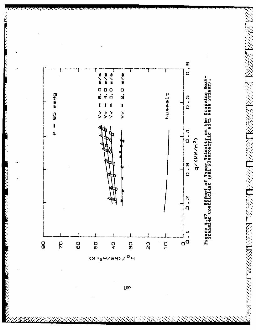
co C
4J4
EEE E
0 00 0
E ci I r40
E mI
In >> > -
'A to
',---I.
m~% wtb.. r
4 .. rr.
44
00
4W-
%I~r
0
1090
(D 00 0 0 f N ' ""-
* .4.*,*.-..

(40.
4J0
4
lu w
GWA
G) umE"
.4
S ALlI.40
in m9
110

For this thesis, data obtained during filmwise condensa-
tion was used in the Modified Wilson method to determine the .
Sieder-Tate coefficient. The primary reason for using film-
vise data was that known correlations for predicting the
filnwise heat-transfer coefficient were available (i. e.
Nusselt or Fujii-Honda). These could be easily used for the
Modified Wilson Plot method.
During filmwise condensation, a relatively large temper-
ature variation exists around the circumference of the hori-
zontal tube [Ref. 45]. Since this is the case, theSieder-Tate coefficient determined using filmvise data would
underpredict the inside heat-transfer coefficient. This inturn would result in larger errors for the dropwise heat-
transfer coefficient.In order to get an understanding of the difference in
the inside heat-transfer coefficient resulting from thecircumferential temperature distribution, an alternate
approach to the Modified Wilson method was attempted. In
this case, the dropwise heat-transfer coefficient was
assumed to be equal to a constant, independent of heat flux,
in the Modified Wilson method. In addition, dropwise conden-
sation data obtained from the silver-electroplated copper
tube, condensing at a pressure cf 85 mmHg, were used in the
UILSOI3 data reduction program. Iteration between theconstant value for the dropwise heat-transfer coefficient
and the Sieder-Tate coefficient was continued until ccnver-
gence occurred. A value of 0.0861 was obtained for the
Sieder-Tate coefficient. This shows an 18 % increase in the
inside heat-transfer coefficient compared to the valueobtained using the Fujii-Honda correlation for the Modified
Wilson method (C = 0.0702). The value obtained for the
constant dropwise heat-transfer coefficient was approxi-
mately 46,000 W/m2K. This value is about 18 % lower than the
value obtained using the Sieder-Tate coefficient based on
%--J.
.. * *4~ 5 .** * .. *.,. ~ , ~- - % **+.-**-I i . I+ i . .I
I. I
I+i- !+ - i- w - - - - . I . _
I! -I 1 i 1 l -i - - + I +- -i ~ . I . ,,i I- 'a .

U..:
the Fujii-Honda correlation at the highest heat flux (see
Figure 4.45) and, as can be seen from the Figure, a larger
difference in the dropwise heat-transfer coefficient occurs _at the lower heat fluxes. Thus, there is a significantdifference between the results obtained from these twoModified Wilson methcds, and a thorough investigation iswarranted to determine which method is more accurate.
112
.. .
V:'-
o -. 4-.

7w.
.
V. CO]KgoNS D RAVEC _ENNDAUQ
A. CONCLUSIONS
1. Using No-Stik, Earalon-333, and NRL fluoroepoxy coat-
ings, dropwise condensation was promoted in excess of11,000 hours. However, for these coatings, enhance-
ment of the outside heat-transfer coefficient islimited (0-2 times filmwise) by coating thicknesseswhich were greater than 5.0 )im.
2. Using NRL fluoroacrylic coatings, dropwise condensa-tion was promoted in excess of 9,000 hours on roughsubstrate surfaces. Outside heat-transfer coeffi-
cients were enhanced by a factor of 4 to 8.
3. Using Parylene-D coatings, dropwise condensation waspromoted in excess of 5,500 hours. Outside heat-
transfer coefficients can be enhanced by a factor of
2 to 4, depending on the coating thickness.
4. Using vacuum-deposited gold coatings, dropwisecondensation was promoted in excess of 8,000 hours.
5. Excellent dropwise condensation was obtained with thesilver-electroplated tutes. Outside heat-transfer
coefficient enhancements of 8-12 were obtained undervacuum conditions, and enhancements of 30-40 were
obtained at atmospheric conditions. However, the
uncertainty in the results must be considered when
large dropwise heat-transfer coefficients areottained. "t"
6. Dropwise data obtained from silver-electroplated
copper and 90-10 CuNi tubes provide further evidence
that the effect of thermal constriction resistance on pe
the dropwise heat-transfer coefficient is small.
113* .o;
"'2*~

7. .A uniform grit-blasted roughness provides the nechan-
ical interlocking required between the coating and
the substrate for good adhesion. A coarse grit
(number 40) gave the best results.8. A wash primer or gold subcoating greatly reduces f'
substrate corrosion, which significantly improves
coating endurance. However, when a wash primer is
used, a trade off in heat-transfer enhancement must
be made.
9. Variations in coating thickness have the largest
effect on outside heat-transfer coefficient enhance-
ment when polymer coatings are used to promote drop-
wise condensation.
10. Thermal stresses can cause failure of crosslinked
polymer coatings by causing cracks to form, leading
to further deterioration.
11. Surface roughness has little effect on the dropwise
heat-transfer coefficient.
12. The dropwise heat-transfer coefficient can be
improved with increased vapor velocity. Above a
velocity of 6 n/s, further improvement is minimal.
B. RECOMBINDATIOIS
1. Evaluate the change in the dropwise heat-transfer
coefficient after prolonged exposure of polymer coat-
ings to steam condensation. This could give some
measure of the added thermal resistance from water
absorption and substrate corrosion.
2. Re-evaluate Parylene-N ccatings using proper surface
preparation (roughness, grimer, gold flash, etc.).3. Investigate the plasma (glow-discharge) polymeriza-
tion coating technique as a possibility of applying
durable PTFE coatings.
114
'i
4. Evaluate durability and beat-transfer performance of
polymer coatings which are 5.0-10.0 gim thick and
which have a silver or ccpper matrix mixed throughout
the coatings. BEL fluoroepoxies might be suitable.
5. In order to improve coating adhesion, evaluate
effects of different cheial cleaning compounds and
acid etch ing of substrates.
6. Re-evaluate thin-walled tubes, with different thermal
conductivities, coated with NEL fluoroacrylic
excluding the wash primer for thermal constriction
resistance effects.7. Continue research into the use of the modified Wilson
method to obtain a suitable procedure for determing
the Sieder-Tate coefficient for dropwise condensa-
tion. Use a dropwise-prcmoted, instrumented tube to
obtain data for calculation of the Sieder-Tate coef-
ficient directly. Compare this result to those
obtained from filmuise condensation and by usingdifferent correlations in the Sodified Wilson method.
115.

m.4
|.
APPND1Z AUNCERTAINTY ANALYSIS
An uncertainty analysis was conducted using the Kline
and BcClintock method. The details of this analysis was
given by Georgiadis [Ref. 4l]. The same "ERROR" program was
used with some minor changes. A listing of this program was
also given by Georgiadis [Ref. 41).The primary change in the program was to include the
discrepancies found in the values used for substrate thermal
conductivity. A ten percent uncertainty was assumed for
substrate thermal conductivity. Other changes included the
mixing chamber calibration and the Sieder-Tate coefficients.
Values obtained during this thesis were used in the program.Error bars shown in Figures 4.36, '.39, 4.45, and 4.46 are
based on the results obtained from the ERROR program output.
When determining the outside heat-transfer coefficient,from the overall heat-transfer coefficient the controlling(largest) thermal resistance contributes the largest errors.
As discussed earlier, for thick-walled low thermal conduc-tivity substrates, the wall resistance can control theprocess and small errors in sustrate thermal conductivitycan cause large errors in the outside heat-transfer coeffi-
cient. As also discussed earlier, the inside heat-transfer
resistance can become the controlling resistance when thecondensing mode is dropwise. This is why the importance of
obtaining an accurate value for the Sieder-Tate coefficient
was stressed. The cooling water temperature rise measurementis also a significant source of error since this is used to
determine the overall heat-transfer coefficient. As shownin Figure 4.36, the largest errors exist at the low heat
fluxes and increase with increasing outside heat-transfer
coefficient.
116
4 , % *4 ** ~ . . . 4. **** * *.-.*...4. 4....... 4;N ...... * .. ..... '..i.... .. ' .. ;

COMPUTER PROGRAM USED FOR VILSON PLOT DATA REDUCTION
The following pages contain a listing of the computer
program (WILSON3) used to determine the Seider-Tate coeffi-
cients with the Modified Wilson method.
117
L
-- - --- ---- --- --- ---- --- -'..~~--.---*..~k~:--.'. -. ...

1100! FILE i1AE: WILZOM3!()10~ REVISED: Ocrocer !6. !984c
I ~ ~~~~1050 DATA -278S99S8).2612:..~7E'rOGO READ 741070 DIM Emf(4)1080 L-. 1,31090 LI-.0603251!00 L"-.03492511(11 SEEC)f!U PRINTER 7sI!113 PRINT ;JSIiG ----- elect rUbe-t.1aIl tvoe: ...
1104~ PRINT UJSING -0."". 0 Thtckwai. 1 Thjnual....
F I
110Di-.0!2711!Dt-.31905
1130 02-.01-785.!60 PRINTER :S 701
1 '30 CLEAR 709'"V30 INPUT "tENTER mgNTH. DATE. AND 7I1ME NN:D-D:HH:M4:SS",Bs1200 OUTPUT 709:"?":SS12:'11 -t
22)OUTPUT 709:"D~20ENTEz 702:$AS
1 241 PRINT JS-7A'G "')X.-*!onth. udare ia time 4:A1250 eEE0
IG TM IPUT SNTER OISK :-IUMjER" . ni270 Xr-!r220 O 0 IIT us::' . "'OX.--1IOTE: 0?',ra name ALSNZ390 PRINT 1 UIG '-ISX.'-OLsK nwunoer * "DD1 :Dn
:?'0) IPUTr *"ENrER :IP!JT MO9DE 05A2:L).I:220 8 EEP10 PRINTER I
!,;.4) PRINT 1JS1IG "4X.'ei.*ct nater.ai -~ode:..1350 PRINT U~SING; X... Coooer -;ain-ss stee±""
60 PRIjIT 'JS:IhG -1X .-- _-' unm 30 W1 L'30 TNP'.'T Irnc
372 ?PINT tIS:IG "X.""eiect *Mo correiation ....137 PRINT USG ...... N~s~j
1 375 PRINTER. IS 701~77 :C -C -'R I IT 'JSNG "1SX4. ""usse.- .:orreiarion ;s seo ;or o-1.' IF Io'thE PRINT USING "1bA.'tjtL correiatiin LS '±Se'. :or -4o',
1'7? SEE212130 PRINTER :SI1 :31 PRIT US:IG "X.""Enter tne "&Lve :or *apor "eioc±,tv.no ...13q: INPUT j23 3 PQTIT-rE 1S 7'
i~PRjIT us::"; V'~.la .% Vtc' ".D.DO'$i1390 :7 inc-0 THEN k.:u*3951400 Inc- I THEN Kcwu.16

11 7F lmr-Z TH'-N Ku 7I~~)IF' :nc-3 'HEN4 KCu..uc3
1421 IF irc- THEN~ DL-.3133142 :mc-2 THENI0.12
1 '* Rm..Do'.OGDo/Di)/(-Kcu);a0IF !,-I THE:)
!&Z BEE 0
I ai50 rMpIUr "GltE A NlAME i:0R THE DATA CTLE ".0 Lie;1460 BEEO1 471) INIPUT SNTER IlISERT NUMBER". inn1480 CR EATE B0DAT 0 'Fies.1014'90 ELSE1500 BEE015!0 IFu "GIVE THE 'IAME !IF THE DATA TE. ±e1520 PRINT USING S6X.""Thjs anaivsis is -or data in tile "2P: u1530 BEE?! 541) N PIUT "ENTER THE NJUMBER OF RUNS STORED". Mr±n1550 END T-
1560 BEEF'1570 INPUT "GANE I MIAME :'OR PLOT-DATA :Tl'E".Plor,3
150BEEz?15,30 INjPUT "TNTER !IPTiON ( 1-O)CT.-T-PT.LE,-4V)E.it,1600 BEE '
16' T 'm-l THENi PRINT USTMNG -?6X.- rhLS anaiyisis .Lses *ICT ceacinns",i11;0 VF It6-2 THEN PRIN4T UJSINC "6X.--Ti-iS anaiyS!S uLseS TP reacinas""1641) IF tn THE4 PRINT USING "GX.-"hLs anaisia uses average, oi QC, anci7-ILE reacings.t 11 PRINT JSrIG "6X.-"ThLS anaiy/sisi ncitioes .efld: if eifect""1670 CRE TE 86A7 Plot!. IC1680 ASSIG N C4F leo TO Ploti
1711) IF Imn2 THEN. ENTER i-;&:Inn1720 iFIn-9) 7T-E! C;-.02
'730 IF inn.,O THEN Ci- .071 7 0 j - )1750 3-760 SY-)
1770 Sxs-0730 Sx v -01730 PINT
'l00 PRINT 'USING "!'(.""Iteration' lujmoer!8313 If JT.11 JR j.7 ' TIV320 PRINT
230PRIT UING"2X.'T - Tsar Lmra
35~ I .~>' T-EA : WSG ,llFe TO D_:ie1.360 IF .Jj>O THEM EIITER W Lle:Iflf!370) I r' 1 ND 'j- 7HE.111830! R EAD DATA 7HR0UlP-H THE DATA ACQUISITION ' 'YS77 A?30! Y THE INPljT IODE (Imn. -1?00 BE
1910:NP't"TITER z;40WME.7R READIG" F'320 OUTPUJT 7,09:"*AR A~i AL13? 30 OUTPJ 709:"AS :A**1 41* E:~o-
'5)FO2R I-1 70~ 201360 ElIT ? 3Et
1.19

1980l 11EYT I
2000) OUTPUT 70?:'A SA-'20,10 ptran-.)2020 FOR t-1 TO 5021030 ENTER 7109:Pt2040) Pt~an-Ptran+Pl2050 NEXT 12H60 ptr-an-ptran/502070 OUTPUT 709:"AS SA~"2080 ENTER 709:BvolM0O OUTPUT 709:'*AS -r
c2100 ENTER 709:Bano! tOJUrPUT 709:'AR AFZ0 ALZ4"
212-'0 FOP 1-13 TO 4
V!30 OUTPUT 709:'*S SA"2140 ENTER 709tEnfBI)
160 NEXT I2! 70 OUTPUT 72TRE2180 WAI 22:20 ENTER 7!!:TII20 0 OUTPUT 712:"T2ZR2E"
2210 WArl 22220 ENTER 713:T2
223 1UTPlJT 7!!.:"TlR2E"2240 WAIT 212251) ENTER 71-3:71.2
227 0 CLEAR 71323 0 ELSE
.129! REPD DATA FROM A JSER-SPEC777D rLE T -F iP'JT MODE (m 2100 ENTER
73TO ZN :F
Z ?-30 TjklNTsv1Em(Z))ra -,U)a.l 7 7 ) 5
2 '6 0 IF jlj-) 7RECl-1370 Er S(.)2220 PRINT USINtG...P ID."2400 PRINT USING...7 =-)D0"7
Z41 IF zr'>.S liHEN
A -) RIN T -'CT A4ND -C 0117ER lORE 71HAM' 0).5:441 bE z-2450 ThP'JT "'K 7O 0 ,' HEAD ( I Y' .0 -1 '.k I4 6 G END :F
'4170 2RINT LJS:.ru;.-OT (O)CT) '..2:T-7-
2430 PRINT USING .. T (7--rL C) - . 2"2490 :F Ok I-) -ND 1)-'.5 7HEI -77n2500) Er21-4S ((T)- 71 ±.)/T2'i) 725 10 YF zr->.05 -HENI
*2520 BE" '.-
Z5~0 ~ ~N T-~IE JI~ER 'RE TH-~r4 5%'2540 BEEP2550 )-y4FJT '"IK TO ;o- -HEZD (1-.0-1*4)7-,0125-0 :F OkZ-O AND E?-Z>.0' H?~37
250END IF2580 PRINT7EP IS 701
120

2590 7ND71600! i OUL"T=E -E ;_G-ME,)N-jrEZ~jrupA~E 017ERENiCL26;') IF .trn, THENL
26a)END 7F2650 IF 7tm-2 THEN
126 70 T1IT02680 END 7F2690 IF 1tm-3 THEM2700 TF-(TI+Tl)0.52710 T I(T*2*To) -.52 742 - END I'F*272 0 Taviq.Tf4T)*.5
2iJTrise-71-it2750 Lrto-.rriei'LOGuTrat-T;)(Tsat-7.1))2760 Cpw~-rmCo~ Tvg(2770 Rhow-alRhow,( Taig)27130 Kw-;*NK'j Tavg)
21300 Prw-FNProw Tavg)282_0 Mdt-I .0480SE-2468aos"E-3- ,,2310 Md-Mdt(1 .0365-Tf*(1 .96644E-3-Tf-5.252E-6))/.9954342840 'Jf-lid/Rhow:2950 VW - Jf , T.i-Di- 2/Z860 I nrt-' 7HEN T r~se- rise-(.0of":8+i. ott 'I)2870 IF inn-' THENI TrLse" rLSe-.0014*vw-22-80 IF inn-2 '1HEN 7rLSe-Trse-(-.)012-.0023*y,, 2)2881 IF Inn-3 THEN -7rise-Trise-(- 00'l74.00e_ -1)2-32 IF Inn- 71HENJ '7se-7rise-(-002.002.-,t )-213,90 0QmrCa- --~r ise
22 10 Uo-Go '! nro2'320) Re-R~-ho. -O L m.L!wa19?0 Fel-0q401, ie2-s)
4:960 Two-Tiat-32970 Tfiirn-Tsarl3+7,wo.2132280 <fK F zNw TrLt Im)2290 Rhoi- NRrhow Tfirn)
20Hg Ne.*-<f Tsar 2* S79*wft.p/M±.FOI0m) Tagt.-333#3?021 YF :oc-r 7HEN'
* 122 .375)9op0o ll:
3041) Twsoc- -iat'3o/Ho3050i) F 4SuUoc- jo,T.,joc).oj 7HE'3080 'wo-7woc31570 ';aMO 227930130 END7-30913 CF -I:
*314Q P2-OT-'tL-O^)
121
$ -. -. ~ ~ ' -. 6
7,. 4 1-- %*******\ *

31i0 q2-(D2-0i'-T-Dre*DZ-.c3180 '1 H*5p <U-4
3200 Fe2 -PN Tan (M2 -t2)/(M 2- -13210 D./!).~J1L*e~~±3220 C-c- uwa/FNMwiTavg+Dt)) .1,43'30 IF A8S((Cfc-Cf)/Cfc.J1 THEtI
3250 GOTO 31003260 END IF.3270 L~e)3280 Y-Newu*( 1/lo-Rm)3290! COMPUTE COE=FCET POR THE LEAST-SQUARES-FIT STRAIGHT LINE3300 IF Jo-, THEN OaUTPUT .4Filep:X.Y3310 Sx-Sx+X7320 Sv-Sy+Y3330 Sxs-Sxsi'(*X.33410 Sxy..Sxv4.X-Y3350! STORE R~AW DATA IN A USER-SPECIFIED , ILE- IF INP'JT MiODE c Im)3360 IF Im-' AND J#-O THEN OUTPUT Fe:v.BaPrn.t.m*mT.23370 IF JI-0 'JR jpL-I THEN PRINT USING "13X.5QX. 0.0D) .22X.D.5D"': Tf. TI .Tsat.Lo
3380! BEEP3390 J-.4.'3400 YIF1n- 4ND 11-1) 7HEN'3410 INPUT "DO YOU HAVE MORE DATA (1-Y.0-N))7",Go_,3n3420 Ir'n.J3430 IF on1THEN 18703440 ELSE31450 '_r "01fru±n 7HEN' !870346n END TF:1470 S!If 1r,±n-Sxv-Sy-Sx)/N rL~n-Sxs-Sx 2)3480 Ac-(Sy-S!Sx)/Nrun3&90 Cc'-/SI
'Si0 IF Jo-! THENI Jo.?3520 IF ABS (Cic-Cp/Cic)>.00! 7HE!11530CiCci.3540 PRINT USING "IOX.""Intermiate Si~aer-Tate coeift - Z.DC.35 GOTO '740)3560) ELSEi3570 IF Jo-1) THEN Jp-13580 END' -73590 Tr' jp-' THEN '7403600 E.CIC icc).53610 P.RIN T3620 PRINT USING "'0X.-":3Leer-71&te COeifLC~ent Z. ' D:
3630 PRINT236,11 PRIfNT US,-hIG "!0.**aSt-3SGares Llne:*..3650o PRINT USING "10X..'-~ Slope . ~ S3 660 PRINT USIG '*!0X.'-" intercept = .i.5E"-3r670 PRII.!T3681) IF Irn 1 THEN3690 BEEF3700 PRINT USING "-0X."-1IOTE: *'**ZZ.*** data -Lins are storea Lnfl(&ie1* S:.
72.0 PRINT USING OX."-NOT: Above Aflaiisi jas Der- orrtea *;r *.Iata in ftle
3730 END IF
122

3740 PR::r USiP IG '~, -laza are Srorea --n il 0'.~t3750 ASS!GW ;F e IrC37SO ASSIGNJ Aie T0
1790 lho(T Ro 70.5'--- 174 9-T*(2.62459E-2-T3.034E-0,
3600 RETURN Ro'310 P16II03820 DEF 'NPrw(T)330 Prtj- ICoi t).Fi:Mw(r /FNlj&T
3840 RETURN Prw.3850 ~ED-3860 DEF f4Mwi(T)3970 A-e'47.3/(T"1332.5)3880 Mu-2:. 4E-;5.1 0A3890 RETURN 'I'±
3900 FNEND3919 DEF PlKia(T3920 X-(Te273.15)/27325'3930 Kw-.921 47+X*(2.395-X*41 .80a7-Xo .52S77-.0734*xu)?940 RETURN Kwu3950 FINENDK3960 DEF FNTvsv(Emi)3970 COM /c/ CM7
3980 T-CAO)4000 T-T+C( I)-ErnMi%4010 NEXT4020 r-+.38Z-#-7623E3397 1S5r4030 RETURN Tai)4a) rMEND
45050 DEF FNCzw(T)
~ALM FIE!ID4090 OEF PN?&ann(X)4;00 P-rXPex.
*&21 0 7ann.'P0q)/(P-9)4130 RETURN Tann4 140 FNENOalSO DEF FI4Graa(r)4,60 COil /Cci C(?)A170 Gra.-?l.9853+. 104388*74130 RE'URN Geaca4190 FNEID74Z200 DEF Ft)
P20 F.~i8444,T.(7.09451-T-. .5808E-27474E0 RETURN£2.0 PRN~D4240 DEF Cl4Ha(r?)4250 Hf-470-4k-T042 50 REt!JRN Hi.4270 FHN~D
123

COMPUTER PROGRAM USED FOR HEAT-TRANSFER DATA REDUCTION
The following pages contain a listing of the computer
program (DRP5) used for data acguisition and data reduction.
124

1000! FILE ttemE: ORP51305! REVISED: Octooer 26. 1981-1 010U!1015 COil /Cc., .(7)1020 DIMl EMW(')1'c DATA 0!U69 52.~9-635:257325531030 DATA 24858..73Ei-2692i3.90E1i1035 READ C(%)10411 Di-..O127 ! inside diameter *,i test tuoe1045 Do-.01905 ! O11TSiae diameter oi test tuoe1050t 0U-.01905 13ktsiae Ciameter oi tne inlet end1055 02-.015875 ! 'Jtisiae diameter o- the ottiet enc1060 Dsso-.152& ! nsie di~ameTer oi Stainless stei test section1065 U- .13335 ! onaensing lengtn I1070 AX.PT.Osso Z/41075 L-.1335 Concensing length!080 LI-.360325 !iniet ana "Fin length"1085 L2-.034915 ! 0~riet and "fin len'grn'1090 Kcu.385 7hermnal condtLctivitV ., Cooper1095 PRINTER IS11110 BEEP1105 PRINT !JSI&G "4X.-1:eiect Oet~on:-'1110 PRINT USING "GX.-* Taxing oata or re-orOCeSSing Previou±s data""..15 ORIMT USING *5. Plotting orOYiOUS .1ata ""'120 PRINT USING "SX.""!2 Lanei.Lng.-1,25 PRINT JSINHG Plotting on log- log"""1110 INPUJT Iso11^,5 tso-Iso-I0*'140 IF :5sop THEN??E5
.~45 PRINTER IS !0?1150 CLEAR 71?;155 BEEP!T60 1INPUT "ENTER *Ifl4T. DATE AND (MM:E 0ilD0:i4H:r4Mt:SS". Dares -
1165 QUTP'27 709:flrPl:DareS
i17! ENTER 709:DareSi!30 PRINT ' 1onth. date ano 7imne :':Dates11:5 PR IN T''30 PRINT JSIG -f)X." 90TE: Program name : DRP5.-
2!95 BEEPt-00 rNP!JT "SENTER DISK 'IUMBER"*.Dn,205 PRINT !USING "i6X.""Oic numoer - *-".0D":On
12) BEEP i" lD 035A!~L) r! 5 'tiP'T "ENTER [PT.1D 035A F1r,.:10 SEE?
P20 RINT USIN1G ".'eiect tune wail zvoe".5 PRINT USING *4X.'-" 0 ThLCkWall Thinwall.":20 NPUT Lt
44~5 BEE?1250 PRINT1255 PRIMT USING "AX.""eiect OOZion:..1260 PRINT USING "4X."" O]0rOoWiSe I -lai"*.1165 INPUT rI0o1270 IF Itt' THEN. Do-.01905
Z27 5 IF I.tt"' 7HEN Do-. J-2222980 BEEP'2$5 PRINT USIm'; X.Sectnarerial .:ooe:.*^20 PRINmT USING "Y."" Copper I Sta.,niess Steie-
* 125

1,195 PRINT jS,IG '4,X .'- AWlnUmmu 3 '30: !0 Culli""'3fl0 INPUT I:,c
1315 IF Imc-2 THENJ <cu.&16 7
1320 IF 1mc-3 THEN KcLL45
1230 1F 1mc-3 THEN Di-.O13211335 Rm-0o-.L0G(DoiDl)/(2*c±) IWALL RESISTANCE 30SED ON OUTSIDE AREA1340 PRINTER :S 701
1350 IF 1m- 1 THEN1355 BEEP
10 INPUT "GIV)E A MAME OR THE RAW DATA..F1LE".D-file*S1365 PRINT UJSING **1X.'--rLe name ".1MA":Dj7IeSIWO' CREATE BOAT DFIieS.151375 ASSIGN VFile TO D-filest280 1fg'3 3 mooth tube1385 BEEP13'190 !NPUT "ENTER INSERT NUMBER (0-NO INSERT). Irnn1395 OUTPUT 'Fil:Ifg,Inn..wt140n1 BEEP405 INPUT "ENTER PRESSURE CONDITION (-.-),D
1010 ELSE1415 BEEPi420 INPUT "GIVE 'HE MAME OF THE EX'ISTING )ATA FILE".3-r 1 1 e51425 PRINr USING "IX"Ti nlsswas oertormed o aai ie".lP 0.
1430 BEEP1435 fINPUT "ENTER THE NMUMBER OF RUMS STORED 2l'run14*0 BE=D445 INPU1T "ENITER ORESSURE CONDITION (0-.-). Ipc
1450 ASSIGN 4Ftle TO 0 ;iieS1455 ENTER Fl:gn.w1460 END I1465 I.F 7to- THEIN1470 8 E EWS7 INPUT "NANT ':O CREATE A F!LE POR "Ir vs (1-Y,)*N)".Inf!480 ELTE;485 rni-')1 A90 END-r1495 I7 7nf THEN!500 aBE -';..;505 INPUT "GIVE R .11AME :OR 'Ir ,iS 7T'L".r1510 C.REATE 3DAT Nr-FS2.l5i5 ASSIGN Nri 7O 'Ir;S
150END :F525 3EE?
1530 IPUT "ENTER 13PTION (0-ICT. :-T-PILE-2-AVE)".:tm1535 1Itn-Ttm~l:541) YF Itrn' THEM PqINT USING S*'X."'ThL3 anaiYwSL u±ses OCT readings ...1545 IF Itm-? THEN PRINT USING "1SX.""Thts anaiysis uses -PILE reaoin s'1550 IF 7tm-3 rHEM PRrNT USING "X.ThSanaiysis ises average -)i QCT and T-pILE readings:555 PRIf ;JSNG "16X.""This analysis Lclucs 4flcf i1 *iv'ect ...1563 IF rnn-2 ANrmc'J T'HEN ('i.071^S563 1F 16nn2- AND 'mc-2 THEA Ci-.47201570 IF Irtn-3 THEM ~O8;575 YF 7nh- 7 HEN CL-.,37*!11 80) 5R!IT JSING 6X"ie2r-a efqtLcie~1585 zRI1IT !USIjG ".-:ns~r! nunotr ." n
126
*. '. % .,% -4*~
V * * *

!590 L6E3595 INPUT IVE -1 lAME ':iR PLOT OV Fl.LE-.iies
1600 CREATE 'BDAT PUe.16035 ASSIGNJ Wi o 1 ..
* ,1610 SEEP%1615 iNPUT "ENTER OUTPUT VERSION (0-SHORT. 1-LONG )*.Tb1620 tov.Iov+1
i63 IF low-1 THEN1635 PRINT1640 IF inf-! THEN1645 PRINT USING "*0X.""Data Vwa Jo Ho Qp V~ F Mr1650 -PRINT JSING "IOX.- (m/s) (W/m'Z-K)(4/m 2-0) (U/rn Z) (inks ...1655 ELSE_1 660 PRINT USING .1 OX.""Data V1 ljo 14a .....1665 PRINT USING * 10X.'- (mis) (W/rn2,-K) (U/rn 2-0 (U/mn2 (rn/S
1670 END IF1675 END IF1680 Zx-O1685 Zx2-0 .;630 Zxv'J1695 ZvO0:700 Sx'])1705 Sy.l!710 Sxs-01715 Sxy-Ot720 Go-on- I1725 Reoeat:!1720 Jk31-I
:740 IF i-1 -HEN:75 EEP
!?750 INPUIT ,! IKE TO CREC< 11G 2-ONCENTRAT'ON ?1JA7.q1755 BEE?-
7150 INPUT "VITER ;LOWMETER 1EADING".Fn!765 OUTPUT 709:";R MF60 AL63 VR5"'7 OUTPUT 709:"AS SA*1775 ENTER 709:Etm:790 BEEP!795 INPUT CDfETVOL TAGE lNlE".0k1796 OUTPUJT 709:"AS SA'!797 ENTER 7O9:2voi
!'315 INPUT "3ISCONNECTr VOLTAGE LINE" .0k1916 OUTPUT 709."AS ';V!317 EriTER 709:Vtran120 OUTPUJT 709:"AS CA"
1825 ENTER 709:2ano10 OUTPUT 7O9:"AR AF20 ALZ4 VR- 11935 rOR I-0 TO A
13340 OUTPUT 709:'*AS CA":845 7F 12 7HEN13950 SO:355; FOR K-1 TO 101136 ENTER 709:E,:165 So-so-:IM7 NIEXT K1875 i[1SS/O
1276
~ %~%*%. ~ *.. v.::'~Aw~ V% - :;*:.:.*z: ~ ~ L

*. 6
1880 ELSE
1885 ENITER 709:E%18390 Emi(lD-ABS(E)895 END IF1900 NEXT I ,~
1905 OUTPUT 709:"AS SAV*1910 OUTPUT 713:'"T IR2S"1915 WAIT21920 ENTER 713:Tll1925 OUTPUT 713: "TZR2E1930 WAIT 21935 ENTER 713:T21940 OUTPUT 713:"TIRr'E"1945 WAIT 21950 ENTER 713;T121955 rr-(Trrr)*.51960 *OUTPUT 713:*T3R2E"*1965 IF 111-0 THEN 20301970 BEEP1975 IPIT "ENTER IIANOMETER READING (HL.HR.HRI4)-.Hl.kr.Hrt#1980 BEEP!98S INPUT "OK TO A4CCEPT THIS RUN (1-Y-DEFAULT.--4)"*.k31990 IF Ok?-O THEN1995 J-J-12000 GOTO 17302005 EID IF2010 Phgq*4I-Hr2015 Pwater--ir-Hrw2020 ELSE2025 ENTER Wi*So.aoVrn oEiO.at)Ei2.m()Ef4.n7.2 .Phg.Pi1,ater20301 !F , -l O)R J-20 OR J-rwu T!HENl2035 Nq-72040 ELSE2045 Ng-02150 END rF'055 END IF
200 Tsca*; IT~,,v( (Emi (0 )Eni (i) ).5) COMPUTE STEAM 7EMPERATURE2065 Troom-rNTvsv(EmiB 3))2070) Tcon-PITvou(Emii4))2075 Ps&t-FNPvst('Tst*ai)2'080 Romg-13529- -2*Troom-26 .85) /502085 Rawator-PNRhow( Troom)2090 Ptes:%4phg..~omi- later-Rowater)*9. 799/110002095 Pmgue*ogt/1 ,!3.42
2105 -
2110 Pit p!h2115 T%&twrNTv~c(Ptogt)
220 v gtiN4vve t ( *Aoi212-5 P011q-Ptt..-aavIPtest .-
21*0 Vfnq#,n9q1.0-60.Pmfnqg215 nfwg-lif g '00215 Vfnq-1fn.'02155 BEE.2160 IF lo,.-2 THN2155 pq rj T2170 PqtIT JSIC "'X.""Data tt soe2175 OUTPU2T 7r'9:'*AR ~AFZO ALZO VRS'
1283
% :
* ~ ~ ~ ~ ~ r t . '* .--

2180 OUTPUT 709:"AS !A"2185 END IF2190 IF 1ov-2 AND Nq-l THEN2195 PRINT USING "10X"" P Psat, Ptran Taeas Tsat N
2200 PRINT USING "1OX."" (mm) (kP&) IkPa) (kPa) (C) (C) MalalM ASS"""
2205 PRINT USING "10X,5(30.DD.2X).2(3D.DD.2X).2(i130.D.2X)":Pm.Pkm.Pks.Pk.Tst_a. Tsat.Vfng.Hfng2260 PRINT2215 END IF2220 IF Mfng>.5 THEN2225 BEEP2230 IF I.- AND Nq-I THEN2235 BEEP2240 PRINT L2245 PRINT USING "!OX."Energize the vacu~u system2250 BEEP2255 INPUT "OK TO ACCEPT THIS RUN (t-Y.O-N)?".Ok2260 IF Ok-0 THEN2265 BEEP2270 DISP "NOTE: THIS DATA SET WILL BE DISCARDED!!2275 WAIT 52280 GOTO t7402285 END IF2290 END IF2295 END IF2300 IF 1.-I THEN2305 IF Fm<10 OR Fm>100 THEN2310 lFm-..2315 BEEP2320 INPUT "INCORRECT FM (I-ACCEPT,O-OELETE)".Im2325 IF 1fm-0 THEN 17302330 EID IF2335 END IF2340! ANALYSIS BEGINS2345 TL-FNTvq(Emf(2))2350 Grad-FNGrad((T1+T2)*,5)2355 To-TL+ABS(Eto)/(,0*Grad),! .E+62360 ErI-ABS(Ti-T.)2365 PRINTER IS I.2370 PRINT USING ...TI (OCT) - "".00.30":TI2375 PRINT USING '-.Ti (TC) - "",DD.3D": Ti2380 IF Erl>.5 THEN2385 BEEP2390 PRINT "QCT AND TC DIFFER BY M1ORE THAN 0.5 C"2395 BEEP2400 INPUT "OK TO GO AHEAD (l-Y.0-N)?".Ok-2405 END IF2410 PRINT USING .. DT (OCT) - "".DD.3D":T2-TI2415 PRINT USING ""DT (r-PILE) - "".DD.3D":To-T-2A20 IF Okl-0 AND Erl>.S THEN 33702425 Er2-ABS((T2-T1)-(To-Ti))/(T2-T1)2430 IF Er2>.O5 THEM A2435 BEEP2440 PRIIIT "iOCT AND T-PILE DIFFER BY MORE THAN 5Z"2445 BEEP2450 INPUT "OK TO GO AHEAD (1-Y.04)?".Ok22455 IF Ok2"0 AND Er2>.05 THEN 33702410 E.,D IF
129
*. .o
_Z$ %.%

* 2465 PRINTER IS 7012470 IF I tat HERI2475 Tit-Tl
*2680 T2o-TZ*2485 END IF
2490 IF rt.-2 THEN m.12495 TIL-Ti2500 T~o-To2510 IF Itm-3 THEN2515 Tli-'T1.Ti..5S2520 TZQ.(T24.e)o.52525 END IF2530 Tavg.(TIL+T~o.-.52535 CPW-CNCPW Iawq)2540 Rhoa.FNRhow(Tavg)2545 Md-1 .04005E-2+6.80932E-3w~nm2550 Ilduftd-( 1.0365-! .96644E-3.TI i.5.ZSZE-6.T t-2)/ .95442555 "f fld/Rhow2560 Vw-f/f(PF.Oi^2/4)
255IF Inn-0 THEN T2o4r2o-(-.0124.OOZVw2)
2580 IF rnn-3 THEN T2o.T~o-(-.0C17+.0045svw'2)2585. IF. tnno4 THEN T2o-T2o-(-.0021+.0024*Vw2)2590 Q11d'cpw.4 T2o7T1l)2595 Qp-g/ (P!.0o-L.)2600 Kw-FNKw( Tavg)2605 "uw-FNHuio Tavq)2610 ReL-Rhow-Vw-Di/Muw2615 Prw-FNPrw TavqJ2S20 FoisO.2625 F92-0.2630 Cf-I.S2535 0u-ReL'.8*Prw.33332640 HL-Kw/DI.(Ci-30e.fCVA)2645 Dt-,/PI.0L-'L.L;.*.;t2-F.2.4iL
K-2650 Cfc-(Muw/FN~um(Tavg.0t)) .142655 IF ABSC(Cfc-Cf)/Cfc)>.01 THEN72660 Cf(FCfCc.5
r% 2665 GUMO 26402670 END IFS2675 Pl-PI.(D1+DI2685 MT.(HL-P!/(Kcu-41)),.S2630 P2-Pl1(D4.02)2635 A2-D2-0i.-Pt.ID2)w.S2700 l2-(HLP2/(KcL'A2))- .52705 F.I-FNTazh(tl4LI/1e4.l)2710 F*2-FNTanh(M2t..2)/(M2-L2)2715 Dtc-3/(Pr.0LiLL-eI+2o2)*s4i)2720 IF ABS((Dtc-Dt)/Dtc)>.01 THEN 26402725 Latd.(T~a-TfL)/LGG((Tstea-Ti)/(Tuteaa-T2o))2730 Uo-Q/ (Lmtd'PI-Do*L)Z735 Ho-l/(IUo 0-o/(DL.(L.LIeFe.L.2.F.2)*Ht-Rm)2740 Hfg-FNHf '2( s toam2745 Tw.-Tstoa-pHo2750 Tftjv-TetqamI2+Two/"&2755 Kf-FNKw(TV1m)2760 Rhaf-FNRhow( ifi.m)2765 ftf -FNfluw4 r L 1)
A. 130
w%SN
2770r Ho-GIK-Ro!Zi3-f/M~-09)'.3 L.
2775 Y-Ho§0p .3333'2780 X-go2785 Sx-Sx+X2790 Sy-Sv+Y2795 Sxs-SxseX-22800 Sxy..Sxv+XsY2805 01-5002910 GlossOIL/( 100-25)-(Tsta-Troom)2815 Hfc-FNHf(Tcon)2820 1f.FNHf (Tateas)2825 ?fdv'.O2830 8pm(B'vo100)^2/5.762835s Mdvc-( (8-Qlassw)-dv.'Hf-Hfc) )/Hfg2940 IF A8S((dv-lMdvc)/fldvc)>.01 THEN2845 Mdv(Mdv+Idvc).52850 GOTO 28352855 END IF2860 Mdy.'MdvIqdvc)o.2865 Vq:FNVvst( Tsteaam)2970 Vv "dv.Yg/Ax2875 IF Inf -I THEN2880 F-(9.799-Do-fluf-$fg)/(Vv2-Kf(Tsteam-wo))2885 Nt.'o-Oo/Kf2890 Rekt'lv-Rhof -o/luf2895 Nr-Nu./Ret' .52900 END IF
290SI IovZ2 THEN290PRINT USING "IOX."- T (Inlet) Doita:-T...
2915 PRINT USING "IOX."" OCT TC OCT T-PILE7""2920 PRINT USING "*IOX.Z(OD.DD.2-X).2(0D.30.2X)"T.T. TZ-TI.To-Ti2925 PRINT USING "10X." Vu Rez. ML Uo Ho q
2930 PRINT USING "10X.Z.DD.tX.5(NZ.3DE.IX).flZ.DD"zVw.Rei.Mi.Uo.Ho.QP.Vv2935 END IF2940 IF by" I THEN2945 IF Inf-1 THEN2950 PRINT USING 1:IX.DD.2X.Z.DD.X.2cD.D.X.Z.30E.1X.Z.DD.ZU1(X.3D.DD)":J,VW0.Uo.Ho.0o.Vv.F.Mr2955 ELSE2960 PRINT USING '*IIX.00.2X.Z.0D.2X.2dI1.40E.2X.Z.30E.3X.Z.DD":J.VJw.Uo.Ho.QP.V
2965 END IF2970 END IF297S IF Im-2 THEN2980 IF Inf-I THEN OUTPUT @Nrf:F.Nr2995 OUTPUT WFl.p;Qp.~a2990 END IF2995 IF Ia-I TH4EN3000 BEEP3005 INPUT "OK MO STORE THIS DATA SET (-.-).k30T0 IF 0ks-1 THEN3015 OUTPUT IiL.;SvoL.9aao.1Jtraz.Etp.Emf(O).Eai(t).Eai(2),Ef(3).Eaf(4).Fu.rt.72. Phq .Ptat~r3020 iF Ini-I THEN OUTPUT -*4rf:F,,ir3025 OUTPUT 4hl~p:Qp.Ho3030 ELSE3035 iJ--13040 GOTO 17253045 END IF3e0a0 SEP
131
Iv -

3055 INPUT "%ILL THERE BE ANOTHER RUN (t-.0-N)?",Go~qn3060 Nrun-J3065 IF Go on<)O THEN Reoeat3070 ELSE , I3075 IF J<Nru THEN Repeat3080 END IF3085 PRINT3090 Sl-(Nruri-Sxy-Sv.Sx)/(Nrun-Sxs-Sx'2)3095 Ac-(Sy-SI*Sx)/Nrun3100 IF Ito-! THEN3105 PRINT USING "IOX.""Least-Squares Line for Hnu vs q curve:-""3110 PRINT USING "10X,"" Slope - "",.D.40E":Sl3115 PRINT USING "10X." Intercept - "*.MD.4DE":A.3120 END IF3125 BEEP3130 INPUT "ENTER PLOT rILE NAIE".FplotS3135 ASSIGN *File4 TO FplotS3140 FOR I-I TO Hrun3145 ENTER 4FiL*4:Qp,Ho3150 Xc=LOG(Qp/Ho)3155 Yc=LOG(QP)3160 Zx-Zx+Xc3165 Zx2=Zx2+Xc'23170 Zxy-Zx+Xc*Yc3175 Zy;Zy+Yc3180 NEXT I3185 Bb-(Nrun-Zxy-Zy-Zx)/(Nruw-Zx2-Zx '2)3190 AaEXP((Zy-Bb*Zx)/Nrun)3195 PRINT3200 PRINT USING "10X."Least-sauares line for q = adelta-T-b."3205 PRINT USING "12X.""a - "".Z.4DE":*a3210 PRINT USING "12X."b - ""Z.4DE":Bb3215 IF Ipc=O THEN3220 0ps-3.58E 53225 Hoo-89193230 END IF3235 IF tpc-1 THEN3240 0ps-I.E+6.-3245 Hoo=70073250 END IF3255 Hos=Aa'(I/Bb)-Gps((Bb-t)/Bb)3260 Enr-Hos/Hop3265 PRINT3270 PRINT USING "IOX."'alues computed at q - "",Z.DD,"" (MN/m'2):...;Qps/T.E+
3275 PRINT USING "12X.""Heat-transfer coefficient * ".DDD.DDD."" (kW/m'2.K)... .:Hos/I000
3280 PRINT USING "12X."Enhancement ratio = ".3O.3D":Enr3285 IF Im-i THEN3290 BEEP3295 PRINT33100 PRINT USING "IOX.""NOTE: "",ZZ."" data runs were staorea in file ".IOA":J.
33705 END IF3310 BEEP3315 PRINT3320 PRINT USING "IOX.""NOTE: .ZZ." X-Y pairs were stored in plot data file
1. IOA":J. P fileS3325 IF !nT-I THEN3330 PRINT USING "16X.ZZ. ' " Pairs of Nr-F are *tored in file .*.14A":J.NrfS3335 END IF
132
N. L'2.
i

3340 ASSIGNJ WieT3345 ASSIGN iFL19l TO3350 ASSIGN WVileo TO3355 IF Iso-2 THEN CALL Plot3360 IF Iso-3 THEN CALL Label33t5 IF Iso-4 THEN CALL Lplot3370 END3375 0EF FHP,is(Tstam3380 DIM K(8)3385 DATA -7.691234584. -26.08023896. - 78.1I708548.64 .23285504.-f 18.364682253390 DATA 4.16711732,20.9750676.1.E9.63395 READ K(-)3400 T-(Tsteam+273.15)/647.33405 Sum-0
3410 FOR N-0 TO 43415 Sum-Sum-pK(N)-(t-T)-(N+?)3420 NEXT N3425 ru/T.()TTK(,7T2,c-)(()(r)2K).3430 Pr-EXP(Br)3435 P-22 120000*Pr3440 RETURN P3445 FNEND3450 DEF FNH;(T)3455 Hfg-e2477200-2450*.4T-1O)3460 RETURN Hf g3465 FNEN 03470 0EF FNMw(T)3475 A-247.8/(T4133.15)3480 Ni-2. 4E-5- 10A3485 RETURN Mu3490 FNEND3495 0EF FNVvt(Tt)3500 P-FNPvst(Tt)3505 T-Tt.273.IS3510 X-1500/T3515 FtI/C1*TwI.E-4)3520 F2-1I-EXP-X2)-.5EXPX/X^.S3525 B-.0015- 1.0009424F2-.0004882*X3530 K-2*P/(461 .52*T)
3540 RETURN V3.545 FNEND3550 DEF FNCpw(T)3555 Cpw-4.21 120858-T-(2.26826E-3-T-.44226E-5.2.7142E-7-r))3560 RETURN Cow-10003565 FNEND3570 0EF FNRhowuT)3575 Ro-999.52946+T.(.01269-T-.5.482513E-3-T-1.234147E-5))3580 RETURN Ro3585 FNEND3590 DEV FNPrw(T)3595 Pru-FNCow T)*FNw(CT)/FNKw T)3600 RETURN Prtw3605 FNEND3610 0EV FNKw~(T)3.615 X-'T+273.:5)/273.;53620 Kw--.92247*.Q.8395-X. I .8007-X-( .52577-.0734*.)O)3625 RETURN Kw3630 FHEND3635 0EV VNTanh(X)3640 P-EX4PX)
133

3645 Q-EX(P(-X,3650 Tan-P-t3/(P+Q)3655 RETUIRN Tanri3660 FN'END3665 DEF FNTvsv(Y)
*3670 CON /Cc/ CM7W3675 T-C0O
*3680 FOR 1-1 TO 73685 T-T+C(I).V-13690 NEXT I3695 RETURN T3700 PNEND3705 DEF FNHT)3710 HfT(.089T(.832--*.5637-)3715 RETURN Hf-10003720 FNEND3725 DEF FNGrad(T)3730 Grad-37.9853+. 104388.1'3725 RETURN Grad
370FNEND3745 DEF FNTvsp(P)3750 Tu-1103755 Tl-103760 Ta-(Tt±.Tt)*.53795 Pc-FNPvst(Ta)3770 IP.IAS((P-Pc)/P)>.0001 THEN3775 IF Pc(P THEN4 ti-Ta3780 IF Pc>P THEN TaL-T&3785 GOTO 37603790 EID IF3795 RETURN Ta3800 PFNID3805 DEF FNPvsv(V)3810 P-81'33.SI33+2.23605tE+4.*,3815 RETURN P10820 FNEDD
r
1.34

_- .7 -7
LIST OF REIERENCES
1. Search, H. T. A e tility Study of Heat Transferjipovement inlarn a n. 3. !-- is, I"."RavaIPsTG duate cnoo7, nonterey, Ca., December,1977. 7-
2. ASME Paper No. 6L-WA/H7-3, Mechanism of DropwiseCondensation, by Umur, A., an -iE1T1th-, P- -unz
3. McCormick, J. I., and Westwater J. V. "NucleationSites for Dropwise condensation,t Chem.n. Science,v20, 1965.
4. Reisbig, R.I., "Microscopic Growth Mechanisms inDropwise Condensation," 5-h Int. Heat Transfer
Anierence, v.3., 1974.
5. Graham, C., he imiting Heat Transfer Mechanisms ofDropwise Condensation, .D.-Tesi-T.7. T.- ""
6. Graham, C., and Griffith P, "Drop Size Distributionsand Heat Transfer in Dropwise ondensation," Int.Journal of leal and Mass Iransfer, v.16, 1973. -
7. Tanasawa I and Ochiai, J., "Experimental Study onDropwise Condensation," Eulletin of Japan Society ofIlchanical Engineers. v._,-l -73...
8. ASME Paper No. 75-ht-BBE Measurements of Drojwisest'b tions D uiq Trasien= _-lse -co aT1Zn,y an~affa,-7, Sep emb er l'3--7- ..
9. Zisman, N.A., "Relation of Egailibrium Contact Angleto Liquid and Solid Constitution," Advances inChemislrj Series, v.43, 1964.
10. Hannemann R.J._, and Mikic B.B.," An ExperimentalInvestigation Into The Effect of Surface ThermalConuctlytty on The Rate cf Heat Transfer in Dro~wiseCondensation," Int. J. 1 neat Mass Transfer, v.19,1976.
11. Askanf S.N., and Rose ,.V., "Dropwise Condensationthe Effect of Thermal Frop erties of the CcndenserMaterial," tnt. J. of H.a ila-s TranLfer, v.16, No.2,Felt. 197" ,.:-
135
,%
... * - . ' . .. , ,. ., .... ,..... , ,, ,, * , . .. ,. . ._,,_, _, , .',

12. Rose, J.W., "Effect of Condenser Tube material on HeatTransfer During Dropwise Condensation of Steam " It.,Za.ns 2&, f f , v.21, No.7, July, 1978.
13. Stylianou, SA. f and Rose, J.V., "DropwiseCondensation on Surf aces Having Different ThermalConductivities," 2. Al 2f Jfai Transfer, v.102, XAugust, 1980.
14. Hannemann, R.J. "Condensing Surface Thickness Effectsin Dropwise Conhensation" I . eat Mass Transfer,v.21, 1o.1, January, 1976.
15. Naas P. Straub, J., and Griull, U., "The Influenceof Te Thermal Diffusivity o, the Condenser materialon The Heat Transfer Coefficient In DropwiseCondensation " Beat Tj.sfe_ 1982, 7th Int. HeatTransfer Con., uic, V.5, 19877-
16. Brown, A., and Thomas, M., "Filmvise and DropviseCondensation of Steam at Lov Pressures " ProceIs
9 x eat. eU Trasfe Coneren , V. 9H.
17. Blackman, L., Dewar, A., and Hampson, H., "AnInvestigation of CompouEds Promoting the DropviseCondensation of Steam, jral 2f APlie . is.__t.Z,v.7, 1957.
18. Bernett,fl., and Zisuan W.,"Confirmation ofSponta~eo s S reading By r ater on Pure Gold " The
_____ o Phyra C SqltEZ, v-74, 10.11, 1970.
19. Erb, R. and Thelen, E.,"Xropwise Condensation,. 1ira igna S C *
20. Woodruff, D., and West water, J.. "Steam Condensationon Electroplated Gold: Effect of Plating Thickness,"""-'.~.l 1. J- f Re.tv " Ills 1Kansrer, v.22, 1979. ""-
21. O'Neill, G., Westvater, J. . "Dropvise Condensationof Steam on Electroplated Silver Surfaces," .t. J..qJ and f -, v.27, 1984.
22. Brenner, A., Z -2.4pq itjon 9_ & s, P .(;: lsARA P ci e, Academic ress THc., pg.
23. Holden, K., ai o j -r to- n tat gs for 1>ryheoP~n ~S nU tii o prte o
24. Brydson, J. Ar .Elastics jiteria 4th ed.,
• 136
,., a,,.. . . •.. a .*t .... . .-- ,- - . . . .. ........ ,... .............. *,, , e,.... ,. ... * -*,r',. , ,.,.,'

25. Fish, J.G., "Organic Polymer Coatings," Dis loition~ehnllQ9es for Fils and Coatiggs, Bunsah,.7*
26. Schuessler, P. "Hydrohobic Resins and Surfacefiodifierq," Proldin d~ Annual International
27. Gaynes, N.1. TIsling of _QaA12 Cotns Noyes DataCorp., pg. 41, IV/[.
2. Holden K.M ianniarachchi 1 A.S., Marto, P.J.,, Boone,2. D B. Aoe..., valuation of organic Coatings for
tie fromotion of Dropvise Condensation of Steam," ASKEPaper ASHE linter Annual Meeting, New Orleans,Decejater, 19841.
29. Nasa Levis Research Center Case No. 13,122-1, Ion BeamsutnPe-o iQaQ uo olvmgrs, by Ban-sBr7.
30. Sharma, A. K. and Yasuda, H., "Effect of GlowDischarge Ireatment of Substrates onPa;ylene-S ubst rate Adhesion," J911 nal of Vacuum
31. SadhirRL and Saunders H Z., "Protective ThinFilm Coatings by Plasma PolyMiation," Procedings
32. U.S. Navy Marine Enineering Laboratory Report 71-106,Lt itera are th j2.iof R popwjse
to ~ ~ 11R,1 ox, It ,J y
33. fianvel, J. T. 1.2 mi t AtudX of =wsn~gb"AnE ei 2 ser TWuBes, 1 737
June, 1979.c007ofEy, C,
34. Perkins, P.K0. ge isental Study A.=Pws"sc T.~hesis, 14a va I
P~B~rue~~dL 1nyuredy, Ca., December, 1979.
35. Griffith, J.R., O'Rear, J G. and Reines, S.A.,"Fluorinated Epoxy Resins," QiIfizg, Say 1972.
36. Hunston, D.L., Griffith J.R. and Bowers. DC"Pluoroepoxies: Surface troperies and Ap3lications;f'
37. ASTS Specification D 3359-83, Melsarig A~esg 11XM s , March, 1983.
137

.7k.
* 38. ASTH Specification D 3363-74 (Reap proved 1980), JiHardulf 11~ j Penci 29st ovember, 1974.
39. Poole# move, F* 1 Lq Condegjn of~ Steam onZxEljy=Zjnd-i tlTU Is 'it TFsii HavaiP-g UWeN2XO6L-,- y~t fonia, December,
40. Pujii, T., Honda, H., "Condensation of Steam on aHorizonital Tube," Conde§Atio Heat Trlanf~, ASSE,New York, 1979.
41. Georga adis, I. V Filmuise C_ ___ tio Steam on
Ur-d-u-f5-1--l, montalfiWJ ca., September, 1984.
42. Nobbs, Do N., The 21 Pawwf Vapor Velocity
a __if Bo~U ~
*43. AK IJIt±1iA jeference Bok 2nd ed., American Society
44. 7ouloukian Y. S. and others ~ ii&~ .2rpper-tA OfBft vol. 1, IFI fienum a a rporation,
45. ianniarachchi A. S5 Marto, P. J., and Rose, J * U"Filavise Con~ensatllon of Steam on Externally Finne &Horizontal Tubes," ASEE Publication HTD-Vol. 38, p.133-141, Dacexbftr 19889.
* 138
4%

.. . -... ~. * .. ...
INITIAL DISTRIBUTIONI LIST
No. Copies
4..
1. Defense Techpical Informaticn Center 2Cameron StationAlexandria, VA 22314
2. Liberary, Code 0142 2Naval P stgraduate SchoolMonterey, CA 93943
3. Department Chairman, Code 6 S. 1De artment of Mechanical EngineeringNaval Postgraduate SchoolMonterey, CA 93943
4. Professor Pa 1 J. Mato Code 69x. 5Department o Mechanical EngineeringNaval Postgraduate School .;Monterey, CA 93943
5. Dr. John V. Rose 1Departant of Mechanical EngineeringUniversity of LondonLondon El 4NSEngland !. !.
6. Dr. Vi im ng_fogn DirectoTmfor Heat Transfer' .uD vi on of Engin eering._atignal Science TonationWashington, D.C. 2050
7. Dr. A. S. Wanniarach~hi Code 69Wq 2Department of Mechanical EngineeringNaval Post raduate SchoolMonterey, A 93943
8. Dr. James R. Griffith 1Code 6120Naval Research LaoratoryMonterey, D. C. 20375
9. Dr. D. H. Boone Code 69Bi 1Department of. echanica EngineeringNaira Postgraduate SchoolMonterey, CA 93943
10. ld. Daniel J. Looney 21 La±gaette Ave.Sea Clif, N.Y. 11579
139
~139
i! .!::..
• " ,('.'.,'..';." ." ,',.; ,',," -";;;' ".. ,'' ",'-.'.." ,' ." ," "" "" " ". ° "o "- ", ". ": " -." " " • • .".-".'. ' 'W"'," '.: ' " ' ,% :'-.' , '.. -;w,, . '%'1

41)*
FILMED
7-85
DTICoo%05