heat generation and removal in solid state lasers
TRANSCRIPT

Chapter 12
© 2012 Ashoori et al., licensee InTech. This is an open access chapter distributed under the terms of the Creative Commons Attribution License (http://creativecommons.org/licenses/by/3.0), which permits unrestricted use, distribution, and reproduction in any medium, provided the original work is properly cited.
Heat Generation and Removal in Solid State Lasers
V. Ashoori, M. Shayganmanesh and S. Radmard
Additional information is available at the end of the chapter
http://dx.doi.org/10.5772/2623
1. Introduction Based on the type of laser gain medium, lasers are mostly divided into four categories; gaseous, liquid (such as dye lasers), semiconductor, and solid state lasers. In recent past years, solid state lasers have been attracted considerable attentions in industry and scientific researches to achieve the high power laser devices with good beam quality. In solid state lasers the gain medium might be a crystal or a glass which is doped with rare earth or transition metal ions. These lasers can be made in the form of bulk [1, 2], fiber [3-7], disk [8, 9] and Microchip lasers [10,11].
Optical pumping is associated with the heat generation in solid state laser materials [12]. Moving of heat toward the surrounding medium which is mostly designed for the cooling management causes thermal gradient inside the medium [13]. This is the main reason of appearance of unwanted thermal effects on laser operation. Thermal lensing [14], thermal stress fracture limit [15], thermal birefringence and thus thermal bifocusing [16-19] are some examples of thermal effects.
Optimizing the laser operation in presence of thermal effects needs to have temperature distribution inside the gain medium. Solving the heat differential equation beside considering boundary conditions gives the temperature field.
Boundary conditions are directly related to the cooling methods which lead to convective or conductive heat transfer from gain to the surrounding medium.
In the case of bulky solid state laser systems (such as rod shape gain medium), water cooling is the most common method which is almost used in high power regime. Design of optimized cooling cavity to achieve the most effective heat transfer is the first step to scale up high power laser devices. Then determination of temperature distribution inside the laser gain medium is essential for evaluation of induced thermo-optic effects on laser operation.
An Overview of Heat Transfer Phenomena 342
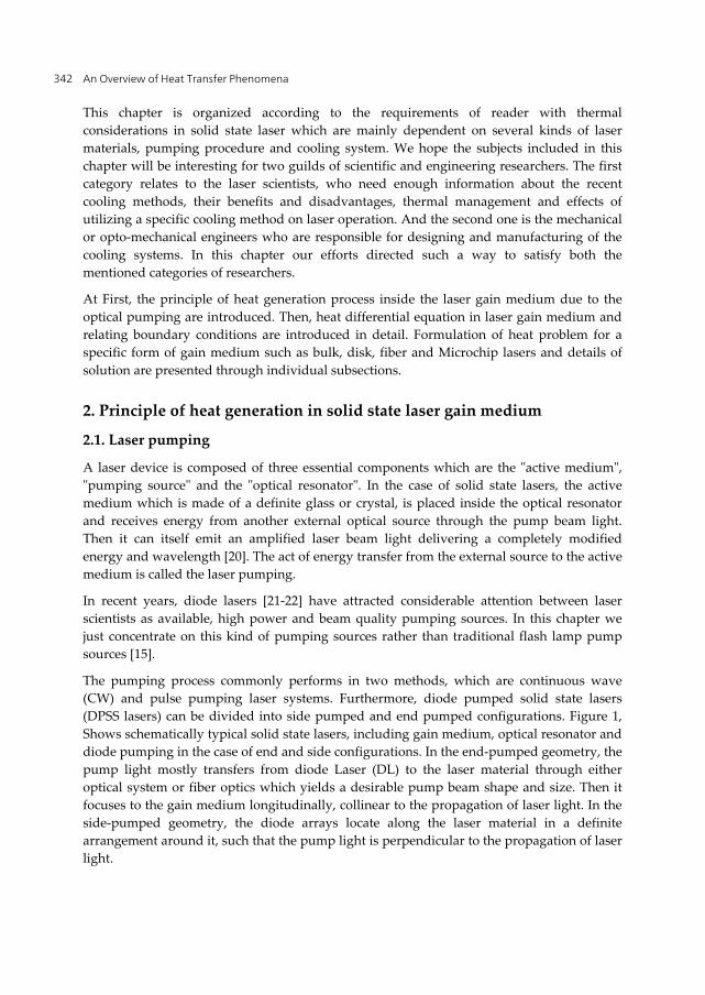
This chapter is organized according to the requirements of reader with thermal considerations in solid state laser which are mainly dependent on several kinds of laser materials, pumping procedure and cooling system. We hope the subjects included in this chapter will be interesting for two guilds of scientific and engineering researchers. The first category relates to the laser scientists, who need enough information about the recent cooling methods, their benefits and disadvantages, thermal management and effects of utilizing a specific cooling method on laser operation. And the second one is the mechanical or opto-mechanical engineers who are responsible for designing and manufacturing of the cooling systems. In this chapter our efforts directed such a way to satisfy both the mentioned categories of researchers.
At First, the principle of heat generation process inside the laser gain medium due to the optical pumping are introduced. Then, heat differential equation in laser gain medium and relating boundary conditions are introduced in detail. Formulation of heat problem for a specific form of gain medium such as bulk, disk, fiber and Microchip lasers and details of solution are presented through individual subsections.
2. Principle of heat generation in solid state laser gain medium
2.1. Laser pumping
A laser device is composed of three essential components which are the "active medium", "pumping source" and the "optical resonator". In the case of solid state lasers, the active medium which is made of a definite glass or crystal, is placed inside the optical resonator and receives energy from another external optical source through the pump beam light. Then it can itself emit an amplified laser beam light delivering a completely modified energy and wavelength [20]. The act of energy transfer from the external source to the active medium is called the laser pumping.
In recent years, diode lasers [21-22] have attracted considerable attention between laser scientists as available, high power and beam quality pumping sources. In this chapter we just concentrate on this kind of pumping sources rather than traditional flash lamp pump sources [15].
The pumping process commonly performs in two methods, which are continuous wave (CW) and pulse pumping laser systems. Furthermore, diode pumped solid state lasers (DPSS lasers) can be divided into side pumped and end pumped configurations. Figure 1, Shows schematically typical solid state lasers, including gain medium, optical resonator and diode pumping in the case of end and side configurations. In the end-pumped geometry, the pump light mostly transfers from diode Laser (DL) to the laser material through either optical system or fiber optics which yields a desirable pump beam shape and size. Then it focuses to the gain medium longitudinally, collinear to the propagation of laser light. In the side-pumped geometry, the diode arrays locate along the laser material in a definite arrangement around it, such that the pump light is perpendicular to the propagation of laser light.

Heat Generation and Removal in Solid State Lasers 343
The pumping geometry and the resultant pump characteristics (such as beam shape and size along the gain medium) play an important role in heat generation and therefore thermal gradient inside the gain medium. The issue will review in details in the following sub-sections for each kind of laser gain mediums.
Figure 1. Simple drawing for two common pumping methods of solid state laser gain medium; a) side pumping b) end pumping. The blue color used for marking the pump light carrying energy from laser diode to the gain medium, and the red beam concerns to the laser resonator mode.
2.2. Heat generation
In solid state lasers, a fraction of the pump energy converts to heat which acts as the heat source inside the laser material [23, 24]. Spatial and time dependence of the heat source causes important effects on temperature distribution and warming rate of the gain medium, respectively. The spatial form is assumed to be the same shape as pumping light [23, 24] and time dependence relates to the pumping procedure, which may perform in CW or pulsed regime. Furthermore, depending on the gain medium configuration and cooling geometry, deposited heat may mostly flow through a preferable direction inside the gain medium and therefore causes thermal gradient. For instance, in traditional rod shape laser mediums with water cooling configuration and also fiber lasers, the main proportion of heat removal occurs through the radial direction which leads to the considerable radial thermal gradient inside the medium. Figure 2 shows a schematic setup of pumping procedure for several kinds of solid state lasers. The dominant directions of heat removal which are associated with the gain medium and cooling system geometry are illustrated.

An Overview of Heat Transfer Phenomena 344
Figure 2. Schematic figure of preferable direction of heat transfer in three common types of solid state lasers; a) disk laser, b) rod, and c) fiber laser
Heat differential equation should be solved for evaluation of temperature and thermal gradient induced by optical pumping in solid state lasers. The general form of heat differential equation in cylindrical coordinate system is given by [25]
2 2
2 2 2
1 ( , , , ) 1 ( , , , ) ( , , , ) ( , , , ) ( , , , )c c
T r z t T r z t T r z t Q r z t c T r z trr r r r z k k t
(1)
Where, ( , , , )Q r z t denotes heat source density ( 3W m ), ck is thermal conductivity, and c are the density ( 3Kg m ) and specific heat ( .oJ Kg C ) of laser gain medium, respectively. Eq.1 denotes to the transient heat differential equation and can specify the time dependence temperature in the case of pulsed pumped laser systems. As we mentioned before,
( , , , )Q r z t can be determined according to the pumping characteristics in several kinds of solid state lasers.
The overall thermal load in the laser gain medium due to the optical pumping can be obtained from
( , )h ov
P Q r z dv P (2)
In which, oP is the pump power and is the fractional thermal load [12]. In the case of diode pumping, the fractional thermal load, originates from two basic phenomenon, which show the main role in heat generation; quantum defect heating [15] and energy transfer upconversion (ETU) [26]. In most cases, the first is responsible for the heat generation and therefore has the main contribution. However it must be noted that, influence of the second

Heat Generation and Removal in Solid State Lasers 345
phenomena cannot be ignored in some cases such as Er doped laser materials. The fractional thermal load in the gain medium is due to the quantum defect and related to the pumping and laser wavelength which are shown by p and L respectively.
1 p
L
(3)
2.3. Bulk solid state lasers
2.3.1. Temperature distribution
2.3.2. Side pumping
Pumping configuration performing by one module is illustrated in Figure3.a [27]. The pump beam emitted by diode laser is focused on the rod by the interfacing optics which consist of two lenses. End view of side-pumping geometry is depicted in Figure 3.b. Transversal directions of pump and signal beams are easily observable.
Figure 3. side pumping geometry; a) Pumping of a laser rod by one module, b) end view of side pumping geometry [27].
In the case of CW pumping of a laser rod, the steady state heat equation can be written as [27]
. ( , ) ( , )h r z Q r z (4)
Where, h is heat flux and associated with the temperature in the rod by
( , ) ( , ),ch r z k T r z (5)
And ( , )Q r z is determined according to spatial variation of pump intensity and is given by
2
0 22( , ) exp
p
rQ r z I
(6)

An Overview of Heat Transfer Phenomena 346
In which, I0 is the heat irradiance on axis. Integration of Eq.4 over rod cross section yields
2
220
21 exp
( )4
pp
rI
h rr
(7)
Substituting Eq.7 into Eq. 5 and integrating to the rod radius or gives the temperature difference inside the rod
2 2 2 2
0 0 01 12 2 2
2 2( ) ln8
p
c p p
I r r rT r E Ek r
(8)
Where 0( ) ( ) ( )T r T r T r and 1E is the exponential integral function [27].
2.3.3. End pumping
One of the common pumping configurations which are used in diode-pumped solid state lasers is end-pumping or longitudinal pump scheme. The pumping beam is coaxial with the resonator beam in end-pumped lasers; it leads to highly efficient lasers with good beam quality.In this geometry, the pumping beam of diode laser(s) is delivered to the end of the active medium by optical focusing lenses or optical fibers. In lower power operations (less than a few watts), end-pumping yields more acceptable results [15]. Today's development of diode lasers and new techniques such as using micro-lenses in beam shaping of diode laser bars make end-pumped lasers very promising specially in commercial lasers [28]. Although end-pumping is a common configuration in solid state lasers which include many types of active medium geometries such as slab and microchip, but it is more commonly used in rod shape lasers. Many end-pumping investigations and results have reported about rod lasers and most of commercial end pump systems involve rod lasers [29-33]. Thus, the discussions in this section are focused on end-pumped rod lasers. Schematic diagram of an end-pumped system is shown in figure 4.
Figure 4. End pump systems major elements [15]

Heat Generation and Removal in Solid State Lasers 347
In order to establish high matching efficiency between resonator beam and pumping modes, in end pumped systems the pumping beam is focused in the active medium with the small beam waist. This issue leads to generation of an intense local heating and then, creation of refracting index gradient inside the laser crystal [15]. As a consequence, the laser rod acts as a thermal lens inside the resonator, which can destroy the beam quality and decrease the output efficiency. Additionally, in contrast to side pumped lasers, heat distribution within the laser material is inhomogeneous in high-power end-pumped lasers, leading to increased in stress and strain [33]. The restricting factors in end-pumped lasers in high power regime are thermal lensing and thermal fracture limit for the laser crystal. The aforementioned restrictions make thermal problems very important in end-pumped lasers especially in high-power systems.
From the thermal point of view, the flat top pumping profile is superior to Gaussian profile in high power end-pumped systems, due to the creation of lower thermal gradient inside the laser crystal leading to lower thermal distortions [28]. However, Gaussian pumping profiles is more investigated because of practical considerations in laser resonator design. One of the earliest thermal analysis in end pumped systems is presented in [15], which relates to the solution of steady state heat differential equation for Nd:YAG crystal with the assumption of Gaussian pumping profile. (Figure 5).
Figure 5. Temperature distribution in an end pumped Nd:YAG laser in the case of end pumping configuration. The pumping and laser beams propagate in z direction of cylindrical coordinate [15].
The temperature profile and thus associated thermal effects in bulky solid state lasers had been the subject of consideration in past years by various authors. In the case of CW pumping, a collection of excellent literatures discussing numerical and analytical thermal analysis can be found in [13, 23, 34-39]. Similar works concerning the transient heat analysis are available in [40].
A famous work which presents analytical expressions for temperature and describes the behavior of temperature inside the rod belongs to Innocenzi [13]. In this work, the laser rod

An Overview of Heat Transfer Phenomena 348
is surrounded by a copper heat sink and exposed to the pump beam with the Gaussian intensity profile as
2
22 2exp exph
p p
P rI z
(9)
Neglecting axial heat flux, the steady state heat differential equation can be solved analytically. The derived temperature difference is obtained as
2 2 20 0
1 12 2 2exp( ) 2 2( , ) ln4
h
c p p
P z r r rT r z E Ek r
(10)
As would be expected, the temperature decays exponentially along the laser rod and have the highest temperature on the pumping surface (z=0).
A common cooling method for end-pumped systems concerns to utilize of water jacket or copper tube surrounding the laser rod and keep the cylindrical surface at the definite temperature. Heat generated inside the gain medium flows to this surface through the heat conduction process in radial direction. Although this method is considered as a simple efficient technic providing considerable heat removal from gain medium, but the uncooled pumped surface of the rod which is in direct contact with air, performs very week heat transfer. This issue may cause undesirable effects, especially in high power regimes [34]. The thermal load on this surface not only increases thermal lensing effects but also restricts the maximum pumping power because of the fracture limit of the crystal, and damage threshold of optical coatings.
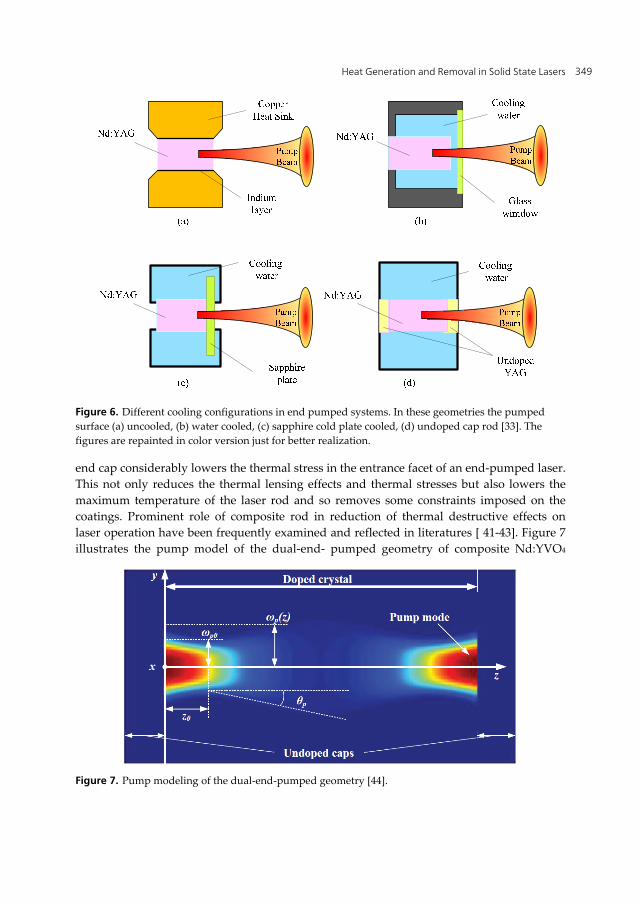
One of the effective strategies to reduce thermal effects is based on the cooling of pumping surface of laser rod. In this respect, three technics to achieve more efficient cooling process have been presented in [33], which are schematically shown in figure 6. In the first method (b), the cooling water is directly in contact with the pumping surface. In the second method (c), a cooling plate cooled by water is mounted in close contact with the rod pumping surface. The cold plate should have large Yang’s module and high heat conductivity. The other method utilizes an un-doped cap on the pumping surface (d). The pumping power does not absorb in the undoped cap so there is not heat load in this region, but using this cap increases the effective cooling surface as well as the ratio of cooling surface to heat generation volume.
The influence of thermal effects on laser gain medium in the mentioned methods has been analyzed using FE method [33]. The maximum temperature decreased almost 30%, and 25% using an undoped cap and a sapphire cooling plate in pumping surface respectively. The maximum stress occurred in the configuration with water cooled pumped surface and reduced to half of uncooled system value using an undoped cap or cooling plate. According to recently developed ceramic laser materials using composite rods with undoped cap could be very promising as the best choice for high power end pumped systems. The undoped
Heat Generation and Removal in Solid State Lasers 349
Figure 6. Different cooling configurations in end pumped systems. In these geometries the pumped surface (a) uncooled, (b) water cooled, (c) sapphire cold plate cooled, (d) undoped cap rod [33]. The figures are repainted in color version just for better realization.
end cap considerably lowers the thermal stress in the entrance facet of an end-pumped laser. This not only reduces the thermal lensing effects and thermal stresses but also lowers the maximum temperature of the laser rod and so removes some constraints imposed on the coatings. Prominent role of composite rod in reduction of thermal destructive effects on laser operation have been frequently examined and reflected in literatures [ 41-43]. Figure 7 illustrates the pump model of the dual-end- pumped geometry of composite Nd:YVO4
Figure 7. Pump modeling of the dual-end-pumped geometry [44].

An Overview of Heat Transfer Phenomena 350
laser[44]. The Nd:YVO4 as the laser gain medium is connected to two YVO4 caps at two ends and the pump energy lunches to it from both ends. As can be seen, every point inside the rod absorbs pump power and experiences heat generation. No absorption inside the caps takes place and therefore, they can show important role in axial heat transfer from end surfaces. Numerical calculations of temperature distribution in composite laser rod can be found in [45]
In the case of pulsed pumping laser rod, interesting numerical analysis has been done by Wang published in [46]. In this work the laser rod is surrounded by a cylindrical heat sink which leads to conductive heat transfer from rod surface to the ambient medium. Schematic figure of the rod and cooling system geometry is depicted in Figure 8-a.
Figure 8. a) simple drawing of laser rod which is surrounded by a cylindrical heat sink, b) time variation of pump power [46]
The laser rod is assumed to be coupled by a fiber-optic to a laser diode; therefore the pump intensity profile with a good approximation has the top-hat shape. Thus the heat source density can be described by
2( ) ,
( , , )0,
zp
p
p
P t e rQ r z t
r
(11)
Where P(t) is a periodic function of time describing pump power in a repetitively pumping regime given by
, 0( )
0, 1
( 1 ) ( )
o
rep
rep
P tP t
r f
P t f P t
(12)
In which Po is the pump peak power, repf is the repetition frequency, and τ is the pump duration time. Figure 8.b tries to simply specify the P(t). Detailed information of solving the transient heat differential equation can be found in [46].

Heat Generation and Removal in Solid State Lasers 351
Figure 9 shows the temperature distribution inside a Nd:YAG laser rod exposing to the pump beam with pulse duration of 300μs, and repetition frequency of 50 Hz. According to the results, the temperature at first increases by passing the time and then becomes nearly constant with small fluctuations which lead the temperature to the steady state condition.
Figure 9. a) Time dependent temperature distribution in laser rod at position z = 0 at 50 Hz repetition rate [46].
2.4. Thin disk lasers
Thin disk lasers are one of the recent frontiers in solid state lasers. The most important features which make the thin disk laser distinguishable between solid state lasers are power scalability, good beam quality and minimal thermal lensing [47,48]. These features are related to the thermal characteristics of the thin disk laser. In disk lasers, active medium is cooled from the disk face. The surface to volume ratio of the disk is large due to the disk geometry, therefore cooling is very efficient and as a result thermal distortion of the active medium is very low. Considering axial heat flow in a thin disk laser there is no thermal lensing in a first-order approximation. In fact, however weak thermal lensing occurs because of two residual effects: first, pumped diameter is typically smaller than the diameter of the crystal and second, thermo-mechanical contribution to the thermal lensing from bending of the disk due to thermal expansion [49].
Thermal lensing is important issue in laser design and operation. This factor can be calculated theoretically using thermo-mechanical modeling softwares. In thin disk lasers, the disk is mounted with a cold plate on a heat sink (figure 10). At the same time the other side of disk is radiated by pumping laser, accordingly there is a temperature difference between two faces of the disk. This will cause a temperature distribution through the disk bulk. Generally the refractive index of materials is depended on temperature; accordingly the refractive index of disk will be a function of position. The other effect is the expansion of the disk due to the temperature distribution formed in it. Also mounting the disk on heat sink causes deformation and stress in the disk. The stress itself will affect the refractive

An Overview of Heat Transfer Phenomena 352
index of the disk crystal. To complete analysis of the effects of the disk on the laser and pump beam, one must calculate cumulative effects of expansion and deformation of the disk, also thermo-optical and stress dependent variations of refractive index [50]. Total effect of the disk on laser beam phase can be calculated by [51]:
0 0 00( ) 2[ [ ( ( , ) ) ( , ) 1].[1 ( , )] ( )]hs z
nr n T r z T n r z r z dz z rT
(13)
In which 0n is refractive index of disk at reference temperature 0T , n T is the thermo-optical coefficient, sn is the changes of refractive index due to stresses, z is the strain in direction of thickness of the disk, 0z is the displacement of back side (High Reflection coated) of the disk and h is the thickness of the disk. As relation (1) shows, optical behavior of the disk is strongly depended to the temperature distribution of disk. The temperature distribution is result of optical pumping and cooling of the disk.
Figure 10. Schematic setup of a thin disk laser; end pump configuration [52]
2.4.1. Pump and cooling configurations
There are two conventional methods for pumping disk lasers; first is (quasi) end pumping and the second is edge pumping. Schematic diagram of end pumping is shown in figure 10. Also figure 11 shows a schematic setup of the edge pumped thin disk laser.
In both mentioned methods, the disk is cooled from the face. The disk can be cooled by jet impingement (figure 12) or cryogenic technique. The disk is mounted with a cold plate on the heat sink. In jet impingement a jet of cooling liquid is sprayed to the cold plate. Different liquids can be considered as coolant which most common is water.

Heat Generation and Removal in Solid State Lasers 353
Figure 11. Schematic setup of edge pumped thin disk laser [53]
Figure 12. Schematic diagram of jet impingement cooling system for thin disk laser [54]
Laser cooling has been an important problem from the invention of the first practical laser in 1960. After invention of laser, cryogenic cooling of solid state lasers has been interested and first time proposed by Bowness [55] in 1963 and then by McMahon [56] in 1969. In mentioned references the conduction cooling is used and laser element was placed in contact with a material with very high thermal conductivity. That material was, in turn, in contact with a cryogen such as liquid nitrogen near 77 K, liquid Ne near 27 K, or He near 4 K.
At cryogenic temperatures the absorption and emission cross sections increases and the Yb:YAG absorption band near 941 nm narrows at 77 K, however it is still broad enough for

An Overview of Heat Transfer Phenomena 354
pumping with practical diode lasers. At 77 K, Yb:YAG crystal behaves as a four-level active medium however in room temperature Yb:YAG is a quasi three-level material. Significant problems associated with quasi-three-level materials like Yb:YAG, such as the need to provide a significant pump density to reach transparency, a high pump threshold power, and the associated loss of efficiency, disappear at 77 K [57]. When the Yb:YAG is cooled from room to cryogenic temperatures, the lasing threshold decreases and slope efficiency increases. Figure 13 shows drop of lasing threshold from 155 W to near 10 W and increasing slope efficiency from 54% to a 63% for a typical thin disk laser [58]. The inset spectral peak in Figure 13 is the 80 K laser output and is centered near 1029.1 nm. At room temperatures this peak is near 1030.2 nm.
Figure 13. Lasing power versus pump power at 15°C (288 K) and 80 K. [58]
2.4.2. Temperature distribution
Specifications of disk laser beam are tightly related to the active medium geometry. The precise geometry of the active medium geometry is also strongly depended to the thermo-mechanical and opto-mechanical properties of the disk and the temperature distribution in the disk. Temperature distribution of the disk can be obtained by solving the heat conduction equation using proper boundary conditions.
The flow of heat generated by the pumping diode radiation through a laser gain media in general form is described by a non-homogeneous partial differential equation:
21 ( , , ) ( , , )( , , )( , ) ( , )c c
T r z Q r zT r zk T dop t k T dop
(14)
In which, Kc is heat conductivity that is assumed to be isotropic and is the heat source density in the laser crystal. In CW regime of output laser, the steady-state temperature distribution obeys the heat diffusion equation
2 ( , , )( , , )( , )c
Q r zT r zk T dop
(15)

Heat Generation and Removal in Solid State Lasers 355
As it is seen the heat conductivity is depended on the temperature and doping concentration (dop) of the crystal. Temperature dependency of YAG crystal in room temperature is not significant and it can be considered as a constant [37] however this approximation would not be valid anymore at cryogenic temperature. Heat conductivity of Yb:YAG crystal which is conventional active medium of thin disk laser can be given by [59]:
0.48 0.4
16
1204( , ) (7.28 7.3 ).94
/dop
c W mk T dop dopT
K
(16)
Characterizing the behavior of the thermally induced lensing effect of the thin disk gain medium is not a trivial task. In order to fully analyze the dynamics of the heat flow and thus the induced n T stresses and strains on the gain medium one must solve the 3-D heat equation with appropriate boundary conditions. This can be accomplished in several ways. The most common is to employ a finite element analysis (FEA) method. Another method is to solve the 3-D heat equation using the Hankel transform. For more details the reader can refer to [60].
Initial estimation of disk thermal behavior can be carried out by calculation of maximum and average temperature of the disk. In thin disk lasers, the thickness of the disk is very low. When the pump spot size is very larger than the disk thickness, one dimensional heat conduction is a good approximation. If pump power of pumpP radiates to the disk in a pump spot with radius of pr , the heat load per area can be given by [61]:
2pump abs
heatp
PI
r
(17)
In which abs is absorption efficiency and is heat generation coefficient in the disk. The heat generation coefficient in the disk is due to the quantum defect and related to the pumping and laser wavelength which are shown by p and l respectively.
1 p
l
(18)
A parabolic temperature profile will be formed along the axis inside the disk due to the loaded heat which is given by:
2
0 , 21( ) ( )2heat th disk
z zT z T I Rh h
(19)
in which , /th disk cR h k is the heat resistance of the disk material and 0T is the temperature of the disk’s cooled face. Also z is the distance along the disk axis in the thickness of the disk and h is the thickness of the disk. In particular, one can calculate maximum temperature from relation (19) which is given by

An Overview of Heat Transfer Phenomena 356
max 0 ,12 heat th diskT T I R (20)
also the average temperature in the disk thickness can be given by
0 ,13av heat th diskT T I R (21)
In this way using relations (19) to (21) one can evaluate, temperature distribution and maximum and average temperature in the disk in one dimensional heat conduction approximation.
2.5. Fiber laser and fiber amplifiers
2.5.1. Introduction to fiber geometry and cooling methods
In recent years, design and manufacturing of high efficient fiber lasers which deliver excellent beam quality, has made them as the main adversary of other types of high power solid state lasers, such as bulk and thin-disk lasers. Achieving to multi-kilowatt output powers [7, 62] with diffraction limited laser beam could be considered as the unique record in laser technology. This progress can be attributed directly to the capability of more efficient cooling procedure in fiber lasers, which originates from inherent large surface to volume ratio. In fact, thermal load spreads over meters or tens of meters of fibers, which causes convenient and efficient cooling management and therefore avoids thermo-optic problems.
Fiber lasers are consists of fiber core which is mostly surrounded by two coaxial fiber cladding (double clad fiber lasers) and is pumped by diode bars or diode laser at one or both ends. The laser light can only propagate through the fiber core and doesn’t have any role in heat generation inside the fiber.
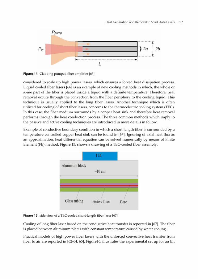
There are two general methods for lunching pump light into the fiber laser which are called as "core pumping" and "cladding pumping". The conventional core pumping was initially used to achieve single mode output laser, in which the pump light was coupled into the small core. On the other hand, small core causes a serious restriction on pump power level [63]. Furthermore, the core size leads to highly localized pump intensity which usually induces thermal damage at the fiber ends. Therefore, cladding pumping has been developed as the proper solution which ensures lunching high pump power into the double clad fiber lasers. In this method the pump light couples into the inner cladding and propagates through it and gradually absorbs in doped core. In both cases, the pump light only absorbs within the core, where heat generation takes place. Figure 14 shows a simple diagram of cladding pumping of fiber laser geometry [63].
In most cases, cooling procedure in fiber lasers does not need any special cooling system and are called passive cooling, which easily can be performed by the air through the convectional process [62-64,65]. However, in modern fiber lasers an active cooling system is
Heat Generation and Removal in Solid State Lasers 357
Figure 14. Cladding pumped fiber amplifier [63]
considered to scale up high power lasers, which ensures a forced heat dissipation process. Liquid cooled fiber lasers [66] is an example of new cooling methods in which, the whole or some part of the fiber is placed inside a liquid with a definite temperature. Therefore, heat removal occurs through the convection from the fiber periphery to the cooling liquid. This technique is usually applied to the long fiber lasers. Another technique which is often utilized for cooling of short fiber lasers, concerns to the thermoelectric cooling system (TEC). In this case, the fiber medium surrounds by a copper heat sink and therefore heat removal performs through the heat conduction process. The three common methods which imply to the passive and active cooling techniques are introduced in more details in follow.
Example of conductive boundary condition in which a short length fiber is surrounded by a temperature controlled copper heat sink can be found in [67]. Ignoring of axial heat flux as an approximation, heat differential equation can be solved numerically by means of Finite Element (FE) method. Figure 15, shows a drawing of a TEC-cooled fiber assembly.
Figure 15. side view of a TEC-cooled short-length fiber laser [67].
Cooling of long fiber laser based on the conductive heat transfer is reported in [67]. The fiber is placed between aluminum plates with constant temperature caused by water cooling.
Practical models of high power fiber lasers with the unforced convective heat transfer from fiber to air are reported in [62-64, 65]. Figure16, illustrates the experimental set up for an Er:

An Overview of Heat Transfer Phenomena 358
ZBLAN double-clad fiber laser. Fiber is placed inside the resonator and is pumped from one end by a diode laser after passing the pump beam from the designed optics.
Figure 16. experimental set up for high power Er: ZBLAN fiber laser [64]. The fiber is pumped by a diode laser at one end.
Figure 17 shows another example relating to high power Yb doped Fiber laser (YDFL), which is pumped from both ends [62]. Convectional cooling process from fiber to air is freely established. Pump power is delivered from two diode stacks propagate from the both ends toward the fiber center and cause two individual heat sources inside the fiber.
Figure 17. experimental arrangement of double clad YDFL pumping with two diode stacks [62]. Freely convective heat transfer to the surrounding air is considered.
Efficient fiber cooling leads to scale up high power lasers without thermal damage and avoiding destructive thermal effects on laser operation. A new technique for thermal management of fiber was examined in [66], which called direct liquid cooling. In this method the fiber was in direct contact with the fluorocarbon liquid. Furthermore, the both ends of fiber facet are in physical contact with the CaF2 windows. This leads to conductive heat transfer from fiber facet to the window and considerable axial heat removal, which allows increasing pump power without thermal damage. This technique was already used in composite bulky solid state laser mediums [24, 41-43] and had found highly operative [68, 69]. Figure 18, shows a drawing of system assembly. The fiber is pumped by two fiber coupled diode lasers from both ends.

Heat Generation and Removal in Solid State Lasers 359
Figure 18. Liquid cooling of long fiber laser. Ld1 and Ld2 fiber coupled diode lasers, L1 and L2 aspheric lenses, W, CaF2 windows, DM dichroic mirrors [66].
2.5.2. Continuous Wave (CW) pumping conditions
Using CW pump sources lead to generation of time independent heat source density in fiber core. Therefore, Eq.1 turns to steady state heat differential equation as
2
2
1 ( , ) ( , ) ( , )c
T r z T r z Q r zrr r r z k
(22)
In which, the azimuthal part of the temperature is omitted due to the cylindrical symmetry of pumping spatial distribution. As we mentioned before, spatial form of heat source density obeys from the spatial form of pump intensity profile lunched to the fiber. "Top hat" and "Gaussian" are two common shapes for the pump beam profile, which are usually considered as the spatial form of heat source density in thermal analysis. Different considerations lead to different differential equations and therefore, needs different solutions. Analytical and Numerical solutions of Eq.1, to specify the temperature behavior inside fiber medium, are reported in various literatures with different approximations and methods.
As we mentioned before, different cooling arrangements lead to different boundary conditions which are conductive or convective heat transfer from fiber periphery to the surrounding medium.
In the case of fiber coupled fiber laser, pump intensity distribution with a good approximation has a top hat profile across the beam. Entering the pump beam inside the fiber core and propagating along the fiber length causes exponential decay in axial direction. Therefore, the heat source density Q(r,z), inside the fiber can be expressed by [70]
02
1 - z e ; r L( , )
0 ; a r <eff
P aaQ r z
b
(23)
Where, oP is the pump power, a is radius of the fiber core, b is the radius of outer cladding,
(1 )eff
LeL
is the effective fiber length, L is the geometrical fiber length and is the

An Overview of Heat Transfer Phenomena 360
effective pump absorption coefficient. Substitution of ( , )Q r z from Eq. 23 into Eq. 22, the heat differential equation for two regions can be written as
2
02 2
1 ( , ) ( , ) 1 - ze ; 0 rLc eff
T r z T r zr P ar r r z a k
(24-a)
2
2
1 ( , ) ( , ) 0 ; a r<T r z T r zr br r r z
(24-b)
Equation 24-a corresponds to the fiber core, where exposes to the pump beam and therefore experiences the heat generation. Equation 24-b relates to fiber cladding that is just responsible for heat transmission to the surrounding medium. Solution of these differential equations give the steady state three dimensional temperature at any point in fiber core T1(r,z) and cladding T2(r,z).Figure 19, illustrates schematically double clad circular fiber geometry under pumping process [70].
a
b
a
b
Figure 19. End (a) and side (b) view of circular fiber laser. Absorption of pump power inside the fiber core causes heat generation which reduces exponentially along the fiber axis [70].
Assuming the outer surface of fiber is in direct contact with a liquid or gas such as air, the convective boundary condition could be defined according to Newton’s law as
22
( , ) ( ( , ))c c
r b
T r zk h T T b zr
(25)
Where, h is heat transfer coefficient [71],Tc is the coolant temperature andT2 (b,z) represents the temperature along the fiber on its cylindrical surface and the first derivative is taken with respect to the surface normal. This equation expresses that the radial thermal flux which arrives at the fiber periphery via the conduction method, removes by the coolant through the heat convection process. Further information about the analytical solution of Equation and some technical points on numerical approach can be found in [70]. The resultant temperature expressions are

Heat Generation and Removal in Solid State Lasers 361
01 02 2
exp( ) 1( , ) ( ( ) ) ;(1 exp( )) c
c
P zT r z CJ r T r aK a L
(26-a)
02 1 0 2 02
exp( )( , ) ( ( ) ( )) ;(1 exp( )) c
c
P zT r z A J r A Y r T r aK a L
(26-a)
Where C, A1 and A2 are constant coefficients which are derived from the boundary conditions as follows
01 2 2
0 0
( ) 1( ) ( )
Y aC A AJ a J a
(27-a)
2
1 0 1( . ( ) . . ( ))4 c
aA h Y b K Y bh
(27-b)
2
2 0 1( ( ) ( ))4 c
aA hJ b K J bh
(27-c)
The temperature is reduced exponentially along the fiber axis due to the exponential decay of heat deposition. Radial dependence in the core includes zero order Bessel function and inside the cladding, linear combination of the first and second kind of zero order Bessel functions are established. This is illustrated in Figure 20 which shows the calculated temperature distribution in the r-z plane of ZBLAN (ZrF4-BaF2-LaF3-AlF3-NaF) double clad fiber. More information about the fiber geometry and pumping characteristics is given in Table 1.
Figure 20. Temperature distribution in r-z plane for the double clad ZBLAN fiber laser [70].

An Overview of Heat Transfer Phenomena 362
Quantity MagnitudeCore radius, a 15 μm Clad Radius, b 370 μm Fiber length, L 4 m thermal conductivity, Kc 0.628 W/(m.K) absorption coefficient, α 2.3dB/m (0.54m-1) Pump Power, P0 42.8 W heat transfer coefficient, h 50 W m-2K-1
ambient air temperature, Tc 300 K
Table 1. amount of physical quantities are used in temperature calculations [70].
In the case of short length fiber laser, analytical approach of temperature expressions for an Er3+/Yb3+ co-doped fiber laser can be found in [26]. Schematic drawing of fiber pumping is illustrated in Figure 21.
1R
0Z
( )pP z
( )sP z( )sP z
( )pP z
2R
Z L
Figure 21. Schematic figure of short length fiber laser with propagation of traveling pump and signal light into positive and negative axial direction[26] .
In short fiber lasers, the pumping energy doesn't absorb completely by one passing of light along the fiber length and thus, the reflected part from the coupler acts as a pump beam delivers inside the fiber at the end face. Heat source function is composed of the proportion of the both the left and right traveling pump beams. The heat source density function with the assumption of Gaussian pump beam shape is given by [26]
2( )[ ( ) ( )] 2 [ ( ) ( )] 2 2( , ) exp 2
2P z P z P z P zps p p s s sQ r z r p
p
(28)
where ( )pP z and ( )sP z are the pump power and signal power in the positive and negative directions, ps and s are scattering loss coefficients at the pump wavelength and signal wavelength respectively and p is the Gaussian radius of the pump light. Figure 22 illustrates an end view drawing of the modeled fiber. As it can be seen, the active fiber is surrounded by a ceramic ferrule which is placed inside a copper tube. Heat conduction from fiber cladding to ceramic ferrule occurs through the fiber cylindrical surface.
The steady state heat differential equations are
2
21 ( , ) ( , ) ( , )[ ] ,0
c
T r z T r z Q r zr r ar r r kz
(29)

Heat Generation and Removal in Solid State Lasers 363
Copper tube Core
CladCeramic ferrule
Figure 22. Geometry of modeled fiber laser
2
21 ( , ) ( , )[ ] 0,T r z T r zr a r br r r z
(30)
and corresponding boundary conditions are
( , ) [ ( , )],c cT r zk h T T r z r b
r
(31)
1 21 2 , ,
T TT T r a
r r
(32)
( , ) 0, 0,T r z z z Lz
(33)
Where, 1T and 2T are the temperatures in fiber core and cladding regions. Eq. 30 relates to the heat removal into the ambient air which is hold at the constant temperature of cT , Eq. 31 ensures the same temperature value at the fiber cladding and core joint boundary (r = a) and Eq.35 expresses the negligible heat transfer from fiber ends into the air because of the small amount of air heat transfer coefficient..
Solution of equations (29)-(33) gives the temperature expressions in fiber core and cladding are given by
0
1 0 0 01 0
01
( , ) ln cos
cos
nc nm
n m
mm
mT r z T C a D A z J rL a
m mC I a zL L
(34)
2 0 0 0 01
( , ) ln cosc m mm
m m mT r z T C r D C I r D K r zL L L
(35)
Where, 0n is nth zero point of the zero order Bessel function of the first kind, 0J and 1J are
the zero and first order Bessel function of the first kind, 0I , 1I and 0K , 1K are the zero and
An Overview of Heat Transfer Phenomena 364
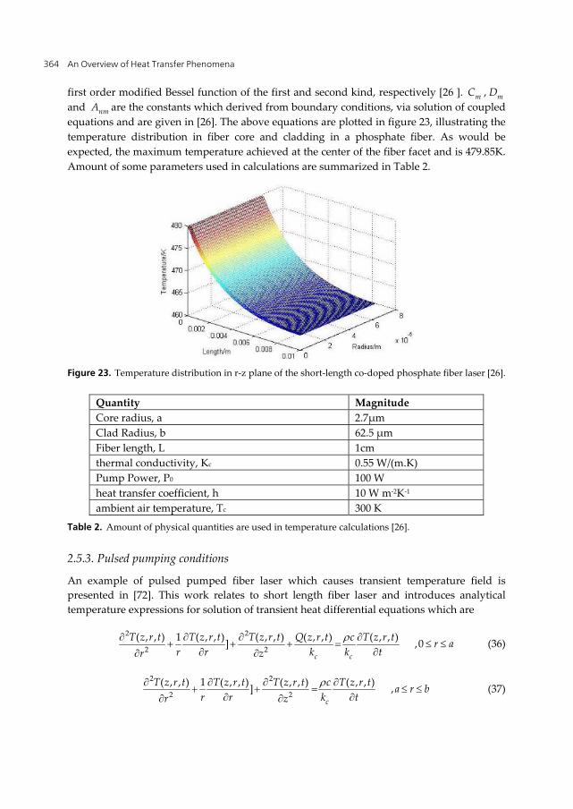
first order modified Bessel function of the first and second kind, respectively [26 ]. mC , mD and nmA are the constants which derived from boundary conditions, via solution of coupled equations and are given in [26]. The above equations are plotted in figure 23, illustrating the temperature distribution in fiber core and cladding in a phosphate fiber. As would be expected, the maximum temperature achieved at the center of the fiber facet and is 479.85K. Amount of some parameters used in calculations are summarized in Table 2.
Figure 23. Temperature distribution in r-z plane of the short-length co-doped phosphate fiber laser [26].
Quantity MagnitudeCore radius, a 2.7μm Clad Radius, b 62.5 μm Fiber length, L 1cm thermal conductivity, Kc 0.55 W/(m.K) Pump Power, P0 100 W heat transfer coefficient, h 10 W m-2K-1
ambient air temperature, Tc 300 K
Table 2. Amount of physical quantities are used in temperature calculations [26].
2.5.3. Pulsed pumping conditions
An example of pulsed pumped fiber laser which causes transient temperature field is presented in [72]. This work relates to short length fiber laser and introduces analytical temperature expressions for solution of transient heat differential equations which are
2 2
2 2( , , ) 1 ( , , ) ( , , ) ( , , ) ( , , )] ,0
c c
T z r t T z r t T z r t Q z r t c T z r t r ar r k k tr z
(36)
2 2
2 2( , , ) 1 ( , , ) ( , , ) ( , , )] ,
c
T z r t T z r t T z r t c T z r t a r br r k tr z
(37)
Heat Generation and Removal in Solid State Lasers 365
In fact, Eq. 36 and Eq. 37 are is written for the fiber core and cladding regions. In this case, the heat source density function is defined as
2
2 22 2( , , ) expin
p p
P rQ z r t z g t
(38)
Where, Pin is the pulse energy and g(t) is temporal shape of pump pulse. The other parameters were previously introduced. The equations (38)-(40) are applicable here as the boundary conditions. Furthermore, the laser system is assumed to be in thermal equilibrium with the ambient air before pumping process which expresses by
( , , ) , 0cT z r t T t (39)
Solution of equations (36) and (37) with the aid of boundary conditions through the integral transform method introduced by Özisik [73] gives the temperature expressions as
0
2 20 00
1
2 2 2 20 0
1 1
( )exp( ) ( )exp( )
2( )cos( )exp[ ( ) ] ( )exp[ ( ) ]
tc c cp p p p
p p
tc c cp m p m mp p m
m p p
T Tk k k
J r t g dclN c c
k k kJ r z t g d
clN c c
(40)
Where
10 00 0
( , , )( ) ( )l rp p
c
Q z r tg J r rdrdzk
(41)
100 0
( , , )( ) cos( ) ( )l rmp p
c
Q z r t mg z J r rdrdzk L
(42)
1
200
2 2 200 02
( )exp( )
2 [1 exp( )]exp( 2 / ) ( ) ( )exp( )
t cp p
r tin cp p p
c p
kg d
cP l k
r J r rdr g dck
(43)
1
2 20
2 22 2
002 2 2 2 2
2 20
( )exp[ ( ) ]
2 [1 exp(1 )cos( )]exp( 2 / ) ( )
( )
( )exp[ ( ) ]
t cmp p m
rinp p
c p
t cp m
kg d
cl P l m
r J r rdrk l m
kg d
c
(44)

An Overview of Heat Transfer Phenomena 366
/m m l (45)
2 2 2 2 2 2 22 0 2( ) ( ) / 2p c p p c pN r k h J r k (46)
0 2 1 2( ) ( ) 0p c p phJ r k J r (47)
Where 0J and 1J are the zero and first rank Bessel function of the first kind, respectively. Assuming square shape for the temporal dependence of pump pulses as bellow, temperature distribution was calculated.
0 0
0 0 0
1 ( 1) ( 1)( )
0 ( 1)n T t n T t
g tn T t t nT
(48)
In which, n denotes number of pulses, 0t is the pulse duration and 0T is pulse period. Figure 24, shows the temperature distribution achieved from the analytical temperature expressions for a typical Er3+/Yb3+co-doped fiber laser. Characteristics of the fiber laser which was introduced in Table 2 were considered in calculations. The fiber is in encounter of pulses with the pulse pump of 1inP W .
Figure 24. Temperature distribution in r-z plane of a pulsed pumped fiber laser at the time of 0.1s [72].
Entering of each pulse into the fiber core causes definite heat load and thus leads to increase of temperature. Figure 25-a, shows the temperature evolution at fiber end facet during the space time of pulse generation. The curves correspond to the time increment of 1ms.
If the pulse period is longer than the space time of heat removal, the temperature will return to the initial value before loading the next pulse. But if the pulse period is shorter than the time which is necessary for completely remove of generated heat, the heat will gradually deposit inside the fiber medium and leads to increase of the fiber temperature. Figure25-b illustrates reduction of fiber facet temperature after the first pulse. At the time of 15ms

Heat Generation and Removal in Solid State Lasers 367
temperature profile has nearly flat shape but the temperature in all positions is 2 C over the initial temperature.
Figure 25. a) radial temperature distribution inside fiber laser at the pump facet during the first pulse pump time, b) reduction of temperature generated by the first pulse during 5ms [73].
Figure 26, illustrates the temperature evolution of the fiber facet at the center versus time. According to that, temperature rises gradually with increasing the time until reaching to almost constant temperature with the small and regular fluctuations. Each fluctuation corresponds to heat generation and then heat removal to outer space during the space time of pulse formation and pulse period time.
Figure 26. a) time evaluation of temperature at the end surface of fiber, b) enlarged drawings of the part of graph a which shows regular fluctuations in temperature profile [73].
2.6. Microchip lasers
In microchip lasers the coated surface of active medium is used as laser's mirror. Popular types of microchip lasers have less than 1 Watt output power. However, recently some reports are demonstrated microchip lasers with several hundred Watts [74-78]. Due to the importance of thermal problems in high power operation, we focus our investigation on this
An Overview of Heat Transfer Phenomena 368
regime. Generally, composite active media are used in high power microchip lasers. The laser material includes a central doped region as the active medium surrounded by an un-doped rim as pumping waveguide.
The microchip laser has a thin active medium with geometry very similar to that of thin disk lasers. Considering the uniform absorbed power distribution, the thermal considerations assumed in thin disk lasers are still valid in microchip lasers. Most common microchip lasers in high power operations are composite microchips with an un-doped rim surrounding active region acting as pump wave guide. The main drawback in this geometry is the non-uniformity of absorbed power distribution which leads to non-uniform temperature distribution. Regarding boundary conditions and non-uniform heat deposition, the temperature distribution in the active medium should be investigated.
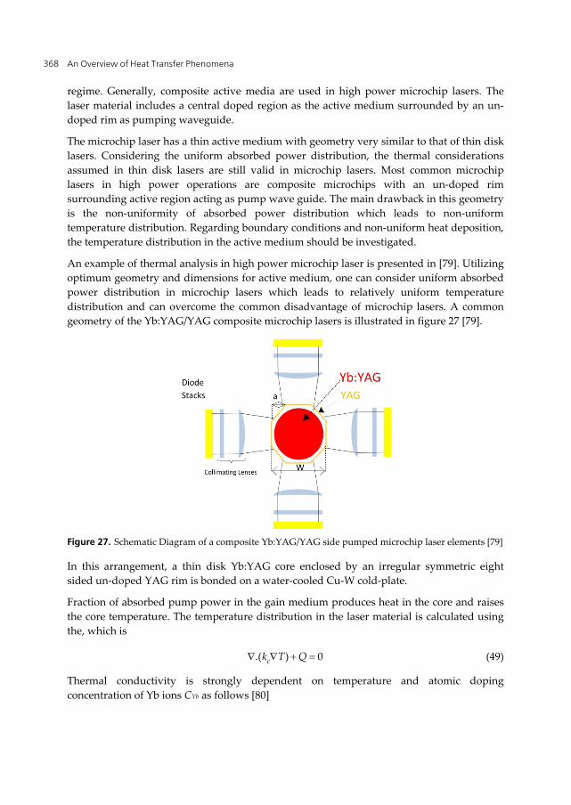
An example of thermal analysis in high power microchip laser is presented in [79]. Utilizing optimum geometry and dimensions for active medium, one can consider uniform absorbed power distribution in microchip lasers which leads to relatively uniform temperature distribution and can overcome the common disadvantage of microchip lasers. A common geometry of the Yb:YAG/YAG composite microchip lasers is illustrated in figure 27 [79].
Figure 27. Schematic Diagram of a composite Yb:YAG/YAG side pumped microchip laser elements [79]
In this arrangement, a thin disk Yb:YAG core enclosed by an irregular symmetric eight sided un-doped YAG rim is bonded on a water-cooled Cu-W cold-plate.
Fraction of absorbed pump power in the gain medium produces heat in the core and raises the core temperature. The temperature distribution in the laser material is calculated using the, which is
.( ) 0ck T Q (49)
Thermal conductivity is strongly dependent on temperature and atomic doping concentration of Yb ions CYb as follows [80]

Heat Generation and Removal in Solid State Lasers 369
0.48 0.46
204 ( , ) 7.28 7.396
YbC
Yb YbKk T C C
T K
(50)
The absorbed power distribution in active medium is calculated using Mont-carlo ray tracing of pumping photons through the optical elements of the system. Heat generation Q is estimated based on the energy difference between the pump and laser photons, given by [81 ]
(1 )pp
lQ P
(51)
In which Pp is local absorbed power density. The heat transfer between the gain medium and air is week, which is described by
0z t
dTdz
(52)
In which z axis coincides on microchip optical axis and t denotes the microchip thickness. Moreover, the temperature of the back face of the cold-plate and contact cooling water were considered as the same. The numerical values used in calculations are given in Table 3.
Quantity magnitude
Pumping wavelength 942nm
Laser wavelength 1030nm
active medium thickness 0.3mm
cold plate thickness 1mm
thermal conductivity [9-82] cold plate 1.9 W/cm.K
cold plate heat transfer coefficient 12 W/cm2.K Table 3. The microchip laser parameters used in numerical calculations.
Heat differential equation (49), was calculated in numerical Finite- Difference method for the described gain medium [79]. This code is used to determine the temperature distribution in the active medium. Figure 28 shows the maximum temperature variation versus a/w ratio for various core diameters with 9 at.% Yb3+ doping concentration. Moreover, the temperature distribution profiles of these cores are also shown in Figure 29.
According to figure 29, the laser gain mediums with the smaller core size experience higher temperatures at the same pump power, which is attributed to the higher thermal load density.

An Overview of Heat Transfer Phenomena 370
Figure 28. Maximum temperature of different microchip core sizes [79].
Figure 29. Temperature distributions of diffrent cores[79].

Heat Generation and Removal in Solid State Lasers 371
Summary
In this work, at first the basic principles of heat generation and removal in all kind of solid state lasers which are Bulk, Disk, Fiber and Microchip configurations are introduced. Then we tried to present a complete collection of solution for heat transfer equation in these types of gain medium regarding to the modern cooling systems, which are available in the literatures. Therefore, this work gives the reader a straight forward way to reach the latest progress in thermal problem in solid state lasers applicable for high power laser design.
Author details
V. Ashoori and M. Shayganmanesh Department of physics, Iran University of science & Technology, Narmak, Tehran, Iran
S. Radmard Iranian National Center for Laser Science and Technology (INLC), Tehran, Iran
3. References
[1] Guangyuan H, Jing G, Biao W, and Zhongxing J (2011) Generation of radially polarized beams based on thermal analysis of a working cavity. Opt. Express. 19: 18302-18309.
[2] Wan-Jun H, Bao-Quan Y, You-Lun J, and Yue-Zhu W (2006) Diode-pumped efficient Tm,Ho:GdVO4 laser with near-diffraction limited beam quality. Opt. Express. 14: 11653-11659.
[3] Zhu X, Peyghambarian N (2010) High-Power ZBLAN Glass Fiber Lasers. Review and Prospect Advances in OptoElectronics.1-23.
[4] Richardson D, Nilsson J, and Clarkson W (2010) High power fiber lasers: current status and future perspectives. J. Opt. Soc. Am. B.27: B63-B92.
[5] Chaitanya Kumar S ,Samanta G and Ebrahim-Zadeh M. (2009) High-power, single-frequency, continuous-wave second-harmonic-generation of ytterbium fiber laser in PPKTP and MgO:sPPLT. Opt. Express. 17: 13711-13726.
[6] Brilliant N. and Lagonik K (2001) Thermal effects in a dual-clad ytterbium fiber laser. Optics Letters. 26: 1669-1671.
[7] Jeong Y, Boyland A, Sahu J, Chung S, Nilsson J, and Payne D (2009) Multi-kilowatt Single-mode Ytterbium-doped Large-core Fiber Laser. J. Opt.Soc. Korea. 13: 416-422.
[8] Ahmed M, Haefner M, Vogel M, Pruss M, Voss A, Osten W and Graf T (2011) High-power radially polarized Yb:YAG thin-disk laser with high efficiency. Opt. Express. 19: 5093-5104.
[9] Beil K, Fredrich-Thornton S, Tellkamp F, Peters R, Kränkel C, Petermann K and Huber G (2010)Thermal and laser properties of Yb:LuAG for kW thin disk lasers. Opt. Express. 18: 20712-20722.

An Overview of Heat Transfer Phenomena 372
[10] Dascalu T, Taira T (2006) Highly efficient pumping configuration for microchip solid-state laser. Opt. Express. 14: 670-677.
[11] Bhandari R and Taira T (2011) Megawatt level UV output from [110] Cr4+:YAG passively Q-switched microchip laser. Opt. Express. 19: 22510-22514.
[12] Fan T.Y (1993) Heat generation in Nd: YAG and Yb: YAG. IEEE J. Quantum Electron. 29: 1457–1459.
[13] Innocenzi M E, Yura H T, Fincher C L and Fields R A (1990) Thermal modeling of continuous-wave end-pumped solid-state lasers. Appl. Phys. Lett. 56: 1831–3.
[14] Fan S, Zhang X, Wang Q, Li S, Ding S, Su F (2006) More precise determination of thermal lens focal length for end-pumped solid-state lasers. Opt. Com. 266: 620-626.
[15] Koechner Walter (2006) Solid-State Laser Engineering 6th edn (New York: Springer) chapter 7.
[16] Moshe I, Jackel S and Meir A (2003)Production of radially or azimuthally polarized beams in solid-state lasers and the elimination of thermally induced birefringence effects. Opt. Lett. 28: 807-809.
[17] Moshe I and Jackel S (2005)Influence of birefringence-induced bifocusing on optical beams. J. Opt. Soc. Am. B. 22: 1228-1235.
[18] Roth M. S, Wyss E. W, Glur H and Weber H. P (2005) Generation of radially polarized beams in a Nd:YAG laser with self-adaptive overcompensation of the thermal lens. Opt. Lett. 30: 1665- 1667.
[19] He G, Guo J, Wang B and Jiao Z (2011) Generation of radially polarized beams based on thermal analysis of a working cavity. Opt. Express. 19: 18302-18309.
[20] Thyagarajan K, Ghatak A (2010) Lasers, Fundamental and Applications: Springer. 467 p. [21] Knight P. L, Miller. A () Diode Laser Arrays: Cambridge University Press. 464 P. [22] Bachmann F, Loosen P, Poprawe R. (2007) High Power Diode Lasers, Technology and
Applications: Springer. 552p. [23] Pfistner C, Weber R, Weber H. P, Merazzi S, and Gruber R (1994) Thermal beam
distortions in end-pumped Nd:YAG, Nd: GSGG, and Nd: YLF Rods. IEEE J. Quantum Electronics. 30: 1605-1614.
[24] Weber R, Neuenschwander B, Mac Donald M, Roos M.B, and Weber H. P (1998) Cooling Schemes for Longitudinally diode laser-pumped Nd:YAGRods. IEEE J. Quantum Electronics. 34: 1046-1052.
[25] CarlslawH.S, and Jaeger (1959) Conduction of Heat in solids: Oxford University Press. 189 p.
[26] Liu T, Yang Z. M and Xu S. H (2008) 3-Dimensional heat analysis in short-length Er3+/Yb3+ co-doped phosphate fiber laser with upconversion. Opt. Express. 17: 235- 247.
[27] Xie W, Tam S. C,Y. L, Liu J, Yang H, Gu J, and Tan W (2000) Influence of the thermal effect on the TEM00 mode output power of a laser-diode side-pumped solid-state laser . Appl. Opt. 39: 5482-5487.

Heat Generation and Removal in Solid State Lasers 373
[28] Clarkson W A (2001) Thermal effects and Their Mitigation in End-Pumped Solid-State Lasers. J. Phys. D. Appl. Phys. 34: 2381-2395.
[29] Huang Y, Tsai H, Chang F (2007) Thermo-optics effects affecting the High Pump power End Punped Solid State Lasers: Modeling and Analysis Opt. Communications. 273: 515-525.
[30] Shi P, Chen W, Li L, Gan A (2007), Semianalytical Thermal Analysis of Thermal Focal Length on Nd:YAG Rods. Appl. Optics. 46: 6655-6661.
[31] Innocenzi M E, Yura H T, Fincher C L, and Fields R A (1990) Thermal Modelling of Continuous-Wave End-Pumped Solid-State Lasers. Appl. Phys. Lett. 56 (19): pp. 1831-1833.
[32] Wang S and etc. (2009) Diode End-Pumped Nd:YAG Laser at 946 nm With High Pulse Energy Limited by Thermal Lensing. Appl. Physics B. 95:721-730.
[33] Weber R and etc. (1998) Cooling Schemes for Longitudinally Diode Laser-Pumped Nd:YAG Rods. IEEE Journal of Quantum Electronics. . 34: 1046-1053.
[34] MacDonald M E, Graf Th., Balmer J. E., and Weber H. P. (1990) Reducing Thermal Lensing in Diode-Pumped Laser Rods. Appl. Phys. Lett. 56: 1831-1833.
[35] Koechner W. (1970) Absorbed pumped power, thermal profile and stresses in a cw pumped Nd:YAG crystal. Appl.Opt. 9: 1429-1434.
[36] Cousins A. K. (1992) Temperature and thermal stress scaling in finite-length end-pumped laser rods.IEEE Journal of Quantum Electronics. 28: 1057-1069.
[37] Brown D. C (1997) Ultahigh-average power diode-pumped Nd:YAG and Yb:YAG lasers. IEEE J. Quantum Electron. 33: 861-873.
[38] Sovizi M, Massudi R. (2007) Thermal distribution calculation in diode pumped Nd:YAG rod by boundary element method. Opt. Laser.Thec.39: 46-52.
[39] Bourdet G. L and Yu H. (2007) Longitudinal temperature distribution in an end-pumped solid-state amplifier medium: application to a high average power diode pumped Yb: YAG thin disk amplifier. Appl. Opt. 46: 6033-6041.
[40] Farrukh U. O, Buoncristiani A. M and Byvik C. E (1988) An analysis of the temperature distribution in finite solid-state laser rods. IEEE Journal of Quantum Electronics. 24: 2253-2263.
[41] Kracht D, Wilhelm R, Frede M, Dupré F. K, Ackermann L (2005 )407 W End-pumped Multi-segmented Nd:YAG Laser. Opt. Express. 13: 10140-10144.
[42] Kracht D, Frede M, Wilhelm R, Fallnich C (2005)Comparison of crystalline and ceramic composite Nd:YAG for high power diode end-pumping. Opt. Express. 13: 6212-6216.
[43] Frede M, Wilhelm R, Brendel M, Fallnich C, Seifert F, Willke B and DanzmannK (2004) High power fundamental mode Nd:YAG laser with efficient birefringence compensation. Opt. Express. 12: 3581-3589.
[44] Yan X, Liu Q, Fu X, Chen H, Gong M and Wang D (2009) High repetition rate dual-rod acousto-optics Q-switched composite Nd:YVO4 laser. Opt. Express. 17: 21956-21968.

An Overview of Heat Transfer Phenomena 374
[45] Wilhelm R, Freiburg D, Frede M, Kracht D, and Fallnich C (2009) Design and comparison of composite rod crystals for power scaling of diode end-pumped Nd:YAG lasers. Opt. Express.17: 8229-8336.
[46] Wang S,Eichler H. J, Wang X, Kallmeyer F, Riesbeck J. Ge. T, Chen J (2009)Diode end pumped Nd:YAG laser at 946 nm with high pulse energy limited by thermal lensing. Appl. Phys. B. 95: 721-730.
[47] Giesen A, Hügel H, Voss A, et al. (1994) Scalable concept for diode-pumped high-power solid-state lasers. Appl. Phys. B. 58: 365-372.
[48] Giesen A and Speiser J (2007) Fifteen Years of Work on Thin-Disk Lasers: Results and Scaling Laws. IEEE J. Sel. Top. Quantum Electron. 13: 598-609
[49] Karszewski M, Erhard S, Rupp T and Giesen A (2000) Efficient high-power TEM00 mode operation of diode-pumped Yb:YAG thin disk lasers. OSA TOPS Advanced Solid State Lasers. 34: 70-77.
[50] Shayganmanesh M, Daemi M.H, Osgoui Zh, Radmard S and Kazemi S.Sh (2012) Measurement of thermal lensing effects in high power thin disk laser. Opt. Laser. Technol. 44(7): 2292-2296
[51] Speiser J and Giesen A (2008) Scaling of thin disk pulse amplifiers Proc. SPIE 6871 68710J.
[52] Giesen A (2005) Thin disk lasers power scalability and beam quality. Laser Technik Journal 2(2): 42-45.
[53] Liu Q, Fu X, Ma D, et al. (2007) Edge-pumped asymmetric Yb:YAG/YAG thin disk laser. Laser Phys. Lett. 4(10): 719–721.
[54] Saravani M, Jafarnia A.F.M, Azizi M (2012) Effect of heat spreader thickness and material on temperature distribution and stresses in thin disk laser crystals. Opt. Laser Technol. 44: 756–762.
[55] Bowness C (1967) Liquid Cooled Solid State Laser. U.S. Patent 3339150. [56] McMahon D.H (1972) Cooling System for Laser Media. U.S. Patent 3676798. [57] Brown D.C (2005) The Promise of Cryogenic Solid-State Lasers. IEEE J. Sel. Topics
Quantum Electron. 11(3): 587-599. [58] Vretenar N, Newell T.C, Carson T, etal. (2012) Cryogenic ceramic 277 watt Yb:YAG
thin-disk laser. Opt. Eng. 51(1): 014201. [59] Contage S.K, Larinove M, Giesen A and Hugel H (2000) A 1-kW CW thin disc laser.
IEEE J. Sel. Topics Quantum Electron. 6(4): 650–657. [60] J.A. Sulskis, Design and characterization of a diode pumped, solid-state, thin-disk
Yb:YAG laser, M.Sc. thesis, University of Illinois (Chicago, 2005). [61] H. Injeyan and G.D. Goodno (editors), High power laser handbook (McGraw-Hill,
2011). [62] Jeong Y, Sahu J. K, Payne D. N, and Nilsson J (2004) Ytterbium-doped large-core fiber
laser with1.36 kW continuous-wave output power. Opt. Express. 12: 6088-6092. [63] Dawson J. W, Messerly M. J, Beach R. J, Shverdin M. Y, Stappaerts E. A, Sridharan A.
K, Pax P. H, Heebner J. E, Siders C. W and Barty C. P. J (2008) Analysis of the scalability

Heat Generation and Removal in Solid State Lasers 375
of diffraction-limited fiber lasers and amplifiers to high average power. Opt. Express. 16: 13240- 13266.
[64] Zhu X and Jain R (2007)10-W-level diode-pumped compact 2.78μm ZBLAN fiber laser.Opt. Lett. 32: 26-28.
[65] Gorjan M, Marinček M, and Čopič M (2009) Pump absorption and temperature distribution in erbium-doped double-clad fluoride-glass fibers. Opt. Express. 17: 19814-19822.
[66] Tokita S, Murakami M, Shimizu S, Hashida M and Sakabe S (2009) Liquid-cooled 24 W mid-infrared Er:ZBLAN fiber laser. Opt. Lett. 34: 3062-3064.
[67] Li L, Qiu H. L. T,Temyanko V. L, Morrell M. M,Schülzgen A,Mafi A, Moloney J. V,Peyghambarian N (2005) 3-Dimensional thermal analysis and active cooling of short-length high-power fiber lasers. Opt. Express.13: 3420-3428.
[68] Frede M, Wilhelm R, Brendel M, Fallnich C (2004) High power fundamental mode Nd:YAG laser with efficient birefringence compensation. Opt. Express. 12: 3581-3589.
[69] Wilhelm R, Freiburg D, Frede M, Kracht D and Fallnich C (2009) Design and comparison of composite rod crystals for power scaling of diode end-pumped Nd:YAG lasers. Opt. Express. 17: 8229-8236.
[70] Ashoori V and Malakzadeh A (2011) Explicit exact three-dimensional analytical temperature distribution in passively and actively cooled high-power fibre lasers. J. Phys. D: Appl. Phys. 44:35103-35109.
[71] H. W. McAdams, Heat Transmission, 3th ed. (McGraw-Hill, 1954). [72] Liu T, Yang Z. M and XuS. H(2009) Analytical investigation on transient thermal effects
in pulse end-pumped short-length fiber laser. Opt. Express. 17: 12875-12890. [73] M. N. Özisik, Heat Conduction (Wiley, New York, 1980). [74] Dascalu T (2008) edged-pump high power microchip Yb:YAG laser. Rom. Rep. Phys. 60:
977–994. [75] Tsunekane M, Dascalu T, and Taira T (2005) High-power operation of diode edge-
pumped, microchip Yb:YAG laser composed with YAG ceramic pump wave-guide. OSA TOPS on Advanced Solid- State Photonics. 98: 603-607.
[76] Dascalu T and Dascalu C (2007) High-power lens-shape diode edge-pumped composite laser. Proc. SPIE. 6785, B67850
[77] Dascalu T and Taira T (2006) Highly efficient pumping configuration for microchip solid-state laser. Opt. Express. 14: 670-677.
[78] Mohammadzahery Z, Jandaghi M, S, Alipour, Dadras S, Kazemi Sh., Sabbaghzadeh J (2012) Theoretical study on thermal behavior of passively Q-switched microchip Nd:YAG laser. Opt. Laser Technol. 44: 1095-1100
[79] Radmard S, Hagparast A, Arabgari S and Mehrabani M (2012) High-Powerb:YAG/YAG Microchip Laser Using Octagonal-Shape Waveguide with Uniform Absorbed Power distribution. Opt. Laser Technol. http://dx.doi.org/10.1016/j.optlastec.2012.09.02
[80] Stewen C, Contag K, Giesen A (2000) A 1-kW CW thin disc laser. IEEE Journal of Selected Topics in Quantum Electronics. 6: 650-657.

An Overview of Heat Transfer Phenomena 376
[81] Fan T Y (1993) Heat Generation in Nd:YAG and Yb:YAG. IEEE Journal of Quantum Electronics. 29: 1457-1459.