hb kbl 1803 035 010 gen rep a4 general report r01 3$*( ,17(17,21$//< /()7 %/$1....
TRANSCRIPT
REF. NO.: #RS
A4 010
NOME FILE: HB-KBL-PAXT-035-010-GEN-REP-A4-General Report-R01
PHASE NAME Drawn
Checked
Approved L. MONTESI C. VICI L. CECCHINI
STAMPS
REV. NO. REV. DESCRIPTION DATE
35% DESIGN
SECTION OF REFERENCE
CATEGORY
REP
GEN
DOC TITLE
General Report
SIZE CLASSIFICATION
OFFICIAL USE ONLY
00 First Issue 14 / 11 / 2016
CUR 1803 - HELICOPTER LANDING ZONE PAX TERMINAL RS HQ, KABUL, AFGHANISTAN
01 Design Revision 13 / 01 / 2017
HELICOPTER LANDING ZONE PAX TERMINAL RS HQ, KABUL, AFGHANISTAN CUR 1803
OFFICIAL USE ONLY HB_KBL_1803_035_010_GEN_REP_A4_General_Report_R01.docx
2 / 35
PAGE INTENTIONALLY LEFT BLANK
DISTRUCTION NOTE: All documents and drawings contained in this design are intended for official use only. Destroy documents and drawings by any method that will prevent Disclosure of Contents or reconstruction of the Document to
not authorized persons.
HELICOPTER LANDING ZONE PAX TERMINAL RS HQ, KABUL, AFGHANISTAN CUR 1803
OFFICIAL USE ONLY HB_KBL_1803_035_010_GEN_REP_A4_General_Report_R01.docx
3 / 35
HELICOPTER LANDING ZONE PAX TERMINAL & PROTECTED WATCHTOWER RS HQ, KABUL, AFGHANISTAN
GENERAL REPORT
INDEX
1. PICTURES INDEX ..................................................................................................................................... 4
2. LIST OF ACRONYMS ............................................................................................................................... 4
3. EXECUTIVE SUMMARY ........................................................................................................................... 5
3.1 REFERENCES .....................................................................................................................................................................5
3.2 CUR 1803 .............................................................................................................................................................................5
4. BACKGROUND ........................................................................................................................................ 6
5. PROJECT SCOPE .................................................................................................................................... 7
6. OVERVIEW................................................................................................................................................ 8
7. REQUIREMENTS ...................................................................................................................................... 9
8. PASSENGER TERMINAL DESIGN ........................................................................................................ 10
8.1 ARCHITECTURE SOLUTIONS .........................................................................................................................................10
8.2 GENERAL UTILITIES ........................................................................................................................................................11
8.2.1 General ..........................................................................................................................................................................12
8.2.2 Electrical, Auxiliary And Special Systems .....................................................................................................................12
8.2.3 Mechanical Systems ......................................................................................................................................................16
8.3 VALUE ENGINEERING (VE) .............................................................................................................................................18
9. PROTECTED WATCH TOWER DESIGN ............................................................................................... 21
9.1 ARCHITECTURE SOLUTIONS .........................................................................................................................................21
9.2 GENERAL UTILITIES ........................................................................................................................................................22
9.2.1 General ..........................................................................................................................................................................23
9.2.2 Electrical, Auxiliary And Special Systems .....................................................................................................................23
9.2.3 Mechanical Systems ......................................................................................................................................................26
9.3 PHASES OF CONSTRUCTION .........................................................................................................................................28
9.4 VALUE ENGINEERING (VE) .............................................................................................................................................32
10. ANNEXES................................................................................................................................................ 35
HELICOPTER LANDING ZONE PAX TERMINAL RS HQ, KABUL, AFGHANISTAN CUR 1803
OFFICIAL USE ONLY HB_KBL_1803_035_010_GEN_REP_A4_General_Report_R01.docx
4 / 35
1. PICTURES INDEX
Figure 1 - Current passenger terminal ............................................................................................................... 8 Figure 2 –PAX TERMINAL: Ground floor with safety flows ............................................................................. 10 Figure 3 – PAX TERMINAL: First floor with safety flows ................................................................................. 10 Figure 4 – HQ RS overall: PAX T location ....................................................................................................... 18 Figure 5 – PAX terminal section ...................................................................................................................... 19 Figure 6 – PAX T: Ground floor functions and flows ....................................................................................... 20 Figure 7 – PAX T: First floor functions and flows ............................................................................................ 20 Figure 8 –PWT: Ground floor, first floor and roof plan .................................................................................... 21 Figure 9 – PWT section 1 ................................................................................................................................ 22 Figure 10 - PWT phase 1 of construction ........................................................................................................ 29 Figure 11 - PWT phase 2 of construction ........................................................................................................ 30 Figure 12 - PWT phase 3 of construction ........................................................................................................ 31 Figure 13 – HQ RS overall: PWT location ....................................................................................................... 32 Figure 15 - PWT field of view .......................................................................................................................... 33 Figure 14 – PWT section 2 .............................................................................................................................. 34
2. LIST OF ACRONYMS
AE Architecture & Engineering AFFF Aqueous Film-Forming Foam ARFF Aircraft Rescue and Fire Fighting ATC Air Traffic Control ATCT Air Traffic Control Tower CUR Crisis response operations Urgent Requirement DF Direct Fire ECP Entry Control Pont FP Force Protection GUs General Utilities IAW In accordance with IOT In order to IDF Indirect Fire IED Improvised Explosive Device HLZ Helicopter Landing Zone HQ Headquarters LZ Landing Zone MMR Minimum Military Requirement NATO North Atlantic Treaty Organization NSPA NATO Support and Procurement Agency PA Public Address PAX Passenger PBIED Person-borne Improvised Explosive device PTDS Persistent Threat Detection System (Aerostat balloon) PWT Protected Watch Tower RS Resolute Support SoW Statement of Work VBIED Vehicle-Borne Improvised Explosive Device WT Watch Tower
HELICOPTER LANDING ZONE PAX TERMINAL RS HQ, KABUL, AFGHANISTAN CUR 1803
OFFICIAL USE ONLY HB_KBL_1803_035_010_GEN_REP_A4_General_Report_R01.docx
5 / 35
3. EXECUTIVE SUMMARY
3.1 REFERENCES
DATE OF ISSUE REMARKS
21/04/2016 SH/CMRB/631/16/310277/001
May 2016 SH/CMRB/637/16-310277/001
02/05/2016 CUR 1803: Construction and relocate a Passenger Terminal and Office for HQ RS HLZ
02/05/2016 STATEMENT OF WORK AE Services - Helicopter landing zone passenger terminal and firefighting utilities - RS HQ, KABUL, AFGHANISTAN CUR 1790/1803
26/06/2016 Minutes of site visit
November 2016 HQ RS Feedback from 35% Design Review – Stakeholders’ Meeting
3.2 CUR 1803
The design solution takes into account SoW requirements, operational inputs and existing constrains through MMRs; it proposes realization of new Passenger Terminal capable of handling the increasing aircraft movements and flow of passengers through safe and secure operations in protected areas and of new Protected Watch Tower to fulfill safe control flights operations.
The new Passenger Terminal project has been developed respecting safety means of egress, operational flows and terminal functions. It is composed by two levels reserved to all passengers functions: check-in and check-out areas, luggage storage, briefing - training room and both indoor and outdoor waiting areas. IAW blast protected building demand, the design solution for building has been aimed to provide a safe and secure reinforced concrete structure
The new Protected watch tower, with capability to visually observe the HLZ (360 degree view) and the Aerostat balloon (PTDS), is located in the south-west part of the helicopter landing zone.
General utilities for facilities in new buildings will include: power and lighting systems; HVAC distribution and water, sewer and drainage systems. For CIS system, including connection with Fire Department Building, CCTV system, IDS and PA system only the conduits will be considered in the design; cables, racks and other active devices will be provided by RS HQ directly.
Before the start of working, local Authorities involved in the coordination of permits and access rights shall be advised and authorizations shall be obtained.
HELICOPTER LANDING ZONE PAX TERMINAL RS HQ, KABUL, AFGHANISTAN CUR 1803
OFFICIAL USE ONLY HB_KBL_1803_035_010_GEN_REP_A4_General_Report_R01.docx
6 / 35
4. BACKGROUND
NATO continues its work to stabilize Afghanistan. In order to better support military operations, NSPA as Host Nation is tasked to construct and relocate a passenger terminal and office for the HLZ (ref. CUR 1803) at HQ RS, Kabul, Afghanistan.
The RS HQ HLZ location is next to the ECP in the western part of the camp.
Due to increased insurgency attacks on the road between BAF and Kabul, decision was made to use rotary wing for all such personnel transportation. Flights have increased over the last year from 1-2 per day to over 100 movement per day. Average passenger count per day is 268 personnel (inbound and outbound) and the current PAX terminal is a temporary facility with a limited capacity and not fit for purpose after this change of mode of transportation.
Air travel is the primary method of transportation and it has increased by 300% since construction of the existing Tower, that is currently improper to ensure air traffic safe and effective control.
HELICOPTER LANDING ZONE PAX TERMINAL RS HQ, KABUL, AFGHANISTAN CUR 1803
OFFICIAL USE ONLY HB_KBL_1803_035_010_GEN_REP_A4_General_Report_R01.docx
7 / 35
5. PROJECT SCOPE
The proposed project will deliver two facilities (PAX Terminal and Protected Watch Tower) to house the HLZ personnel, to provide a safe, secure and protected check–in and holding area for personnel awaiting flights from HQ RS, including secure outdoor waiting area and access to the LZ, and to safely monitor flight activity.
The Protected WT shall be able to:
- directly observe the LZ visually;
- have direct sight of Aerostat balloon (PTDS);
- guarantee direct visibility of flights operations in order to ensure communicate with and
control flights operations.
HELICOPTER LANDING ZONE PAX TERMINAL RS HQ, KABUL, AFGHANISTAN CUR 1803
OFFICIAL USE ONLY HB_KBL_1803_035_010_GEN_REP_A4_General_Report_R01.docx
8 / 35
6. OVERVIEW
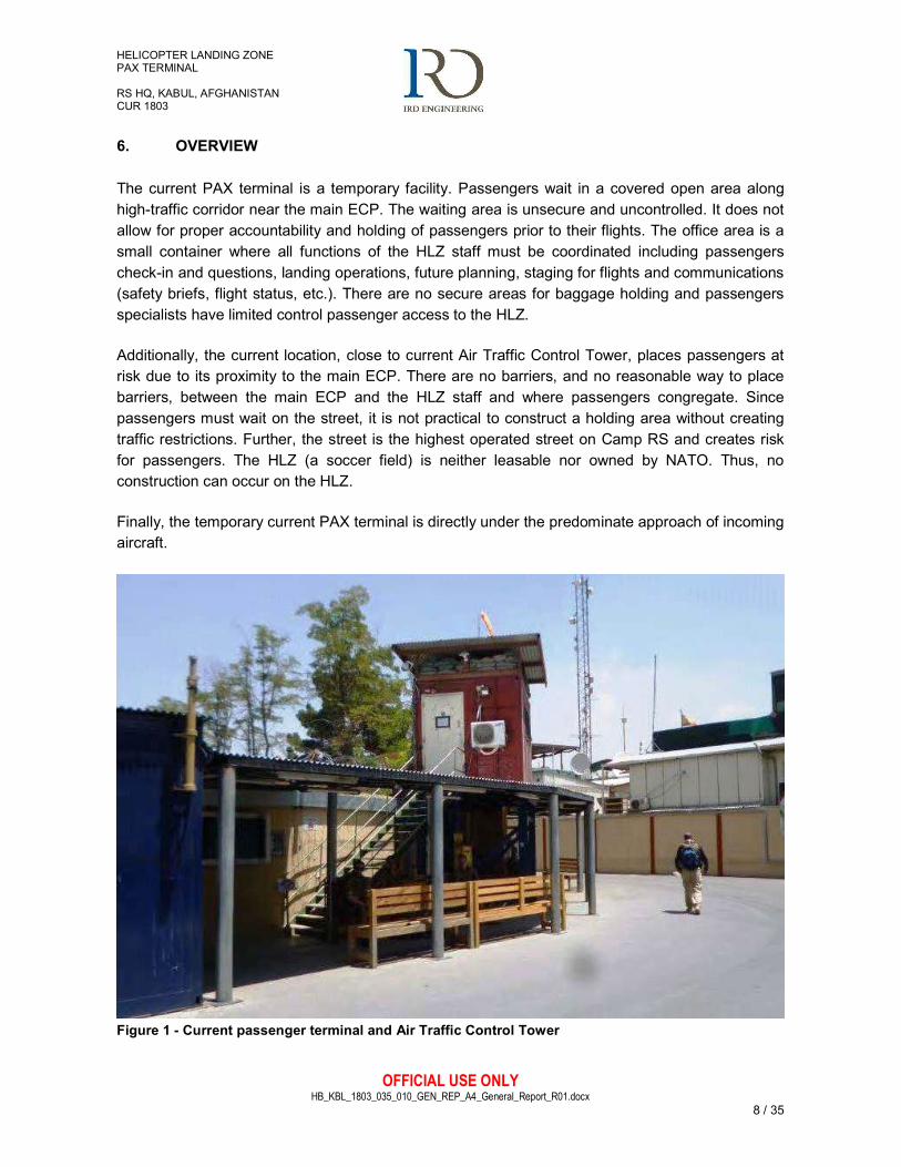
The current PAX terminal is a temporary facility. Passengers wait in a covered open area along high-traffic corridor near the main ECP. The waiting area is unsecure and uncontrolled. It does not allow for proper accountability and holding of passengers prior to their flights. The office area is a small container where all functions of the HLZ staff must be coordinated including passengers check-in and questions, landing operations, future planning, staging for flights and communications (safety briefs, flight status, etc.). There are no secure areas for baggage holding and passengers specialists have limited control passenger access to the HLZ.
Additionally, the current location, close to current Air Traffic Control Tower, places passengers at risk due to its proximity to the main ECP. There are no barriers, and no reasonable way to place barriers, between the main ECP and the HLZ staff and where passengers congregate. Since passengers must wait on the street, it is not practical to construct a holding area without creating traffic restrictions. Further, the street is the highest operated street on Camp RS and creates risk for passengers. The HLZ (a soccer field) is neither leasable nor owned by NATO. Thus, no construction can occur on the HLZ.
Finally, the temporary current PAX terminal is directly under the predominate approach of incoming aircraft.
Figure 1 - Current passenger terminal and Air Traffic Control Tower
HELICOPTER LANDING ZONE PAX TERMINAL RS HQ, KABUL, AFGHANISTAN CUR 1803
OFFICIAL USE ONLY HB_KBL_1803_035_010_GEN_REP_A4_General_Report_R01.docx
9 / 35
7. REQUIREMENTS
The task is to develop plans for an enduring PAX terminal at the HLZ capable of managing 100+ helicopter movements per day (inbound and outbound). New PAX terminal should be capable of handling up to 40 personnel awaiting transportation and it should contain:
- security personnel in Security/In-Out-processing Office: 3
- inspection personnel in inspection area: 2
- check-in personnel and passenger marshals: 2
- outdoor holding area for personnel;
- baggage storage;
- secure access to HLZ;
- check-in area to manifest passengers and provide positive control for accountability and
availability.
The facility will also have the ability to account for all personnel arriving/departing HQ S by utilizing the current TACTICS accountability system, or other automated database of record. Water and refreshments are to be available. Mechanical (HVAC) and electrical systems are required.
In order to perform flight control operations, a new Protected Watch Tower is required. The optimal location for the Tower is at its current location. Watch Tower will have following features:
- personnel in Control cabin: 3
- at least 270 degrees fields of view around (North couterclockwise to East);
- direct sight of the Aerostat balloon (PTDS);
- protection against direct fire, as small arms and shrapnel (no IDF and no blast protection);
- no windows openable, frame and glass;
- CIS connection with Fire Department Building (n. 712).
The HLZ and the new HLZ PAX Terminal shall meet IATA standards for safe and secure operations.
As the current number aircraft movements is expected to continue at the same level or maybe increase, spare capacity should be accommodated for.
HELICOPTER LANDING ZONE PAX TERMINAL RS HQ, KABUL, AFGHANISTAN CUR 1803
OFFICIAL USE ONLY HB_KBL_1803_035_010_GEN_REP_A4_General_Report_R01.docx
10 / 35
8. PASSENGER TERMINAL DESIGN
The design proposes realization of new passenger terminal capable of handling the current aircraft movements and flow of passengers through safe and secure operations, including spare capacity to face the increasing aircraft movements.
8.1 ARCHITECTURE SOLUTIONS
The new building will house the HLZ personnel and will provide a safe, secure and protected check-in and holding area for personnel awaiting flights from HQ RS, including secure outdoor waiting area and access to LZ. It will be located close to an existing access to the HLZ in the east-side of the sport field; to allow the access from new Terminal to HLZ an existing fire hydrant located near existing gate will be moved on the other side of the gate.
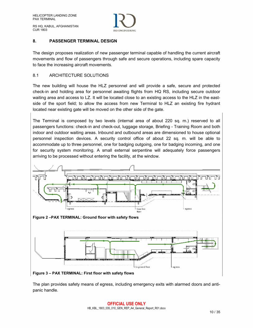
The Terminal is composed by two levels (internal area of about 220 sq. m.) reserved to all passengers functions: check-in and check-out, luggage storage, Briefing - Training Room and both indoor and outdoor waiting areas. Inbound and outbound areas are dimensioned to house optional personnel inspection devices. A security control office of about 22 sq. m. will be able to accommodate up to three personnel, one for badging outgoing, one for badging incoming, and one for security system monitoring. A small external serpentine will adequately force passengers arriving to be processed without entering the facility, at the window.
Figure 2 –PAX TERMINAL: Ground floor with safety flows
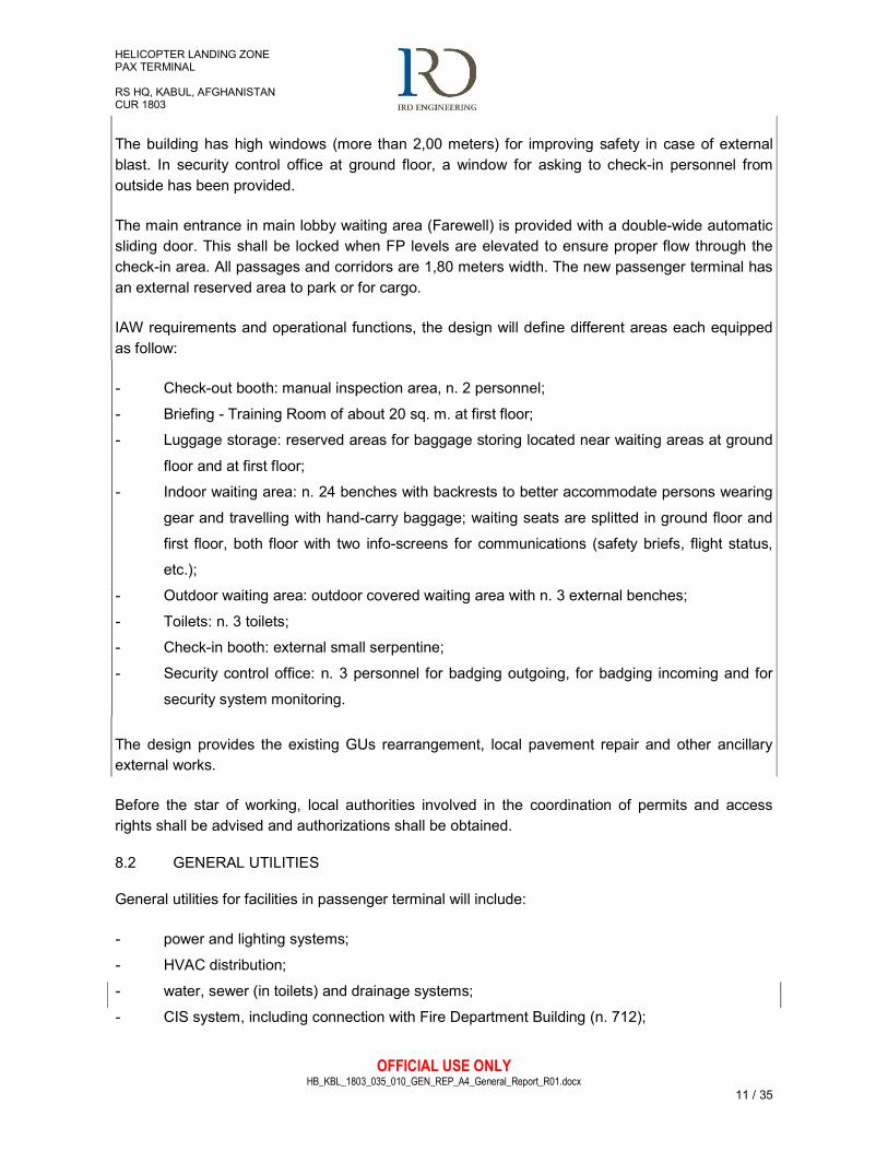
Figure 3 – PAX TERMINAL: First floor with safety flows
The plan provides safety means of egress, including emergency exits with alarmed doors and anti-panic handle.
HELICOPTER LANDING ZONE PAX TERMINAL RS HQ, KABUL, AFGHANISTAN CUR 1803
OFFICIAL USE ONLY HB_KBL_1803_035_010_GEN_REP_A4_General_Report_R01.docx
11 / 35
The building has high windows (more than 2,00 meters) for improving safety in case of external blast. In security control office at ground floor, a window for asking to check-in personnel from outside has been provided.
The main entrance in main lobby waiting area (Farewell) is provided with a double-wide automatic sliding door. This shall be locked when FP levels are elevated to ensure proper flow through the check-in area. All passages and corridors are 1,80 meters width. The new passenger terminal has an external reserved area to park or for cargo.
IAW requirements and operational functions, the design will define different areas each equipped as follow:
- Check-out booth: manual inspection area, n. 2 personnel;
- Briefing - Training Room of about 20 sq. m. at first floor;
- Luggage storage: reserved areas for baggage storing located near waiting areas at ground
floor and at first floor;
- Indoor waiting area: n. 24 benches with backrests to better accommodate persons wearing
gear and travelling with hand-carry baggage; waiting seats are splitted in ground floor and
first floor, both floor with two info-screens for communications (safety briefs, flight status,
etc.);
- Outdoor waiting area: outdoor covered waiting area with n. 3 external benches;
- Toilets: n. 3 toilets;
- Check-in booth: external small serpentine;
- Security control office: n. 3 personnel for badging outgoing, for badging incoming and for
security system monitoring.
The design provides the existing GUs rearrangement, local pavement repair and other ancillary external works.
Before the star of working, local authorities involved in the coordination of permits and access rights shall be advised and authorizations shall be obtained.
8.2 GENERAL UTILITIES
General utilities for facilities in passenger terminal will include:
- power and lighting systems;
- HVAC distribution;
- water, sewer (in toilets) and drainage systems;
- CIS system, including connection with Fire Department Building (n. 712);
HELICOPTER LANDING ZONE PAX TERMINAL RS HQ, KABUL, AFGHANISTAN CUR 1803
OFFICIAL USE ONLY HB_KBL_1803_035_010_GEN_REP_A4_General_Report_R01.docx
12 / 35
- CCTV system, Access control, Acoustic alarm, PA system and info-screens for flights and
communications (safety briefs, flight status, etc.).
Predispositions, wiring and connections for power and mechanical systems are included. Connection to local power system, and in general with all local systems, will be complied with Military instructions.
8.2.1 General
For CIS, CCTV, IDS, PA system, info-screens and other auxiliary and special systems only the conduits (ducting, cable treys and other ancillary civil works) will be considered in the design; cables, racks and other active devices will be provided by Military.
PAX Terminal will be located in an area containing some underground existing GUs (MV cable, water and sewage systems1). Existing underground Medium voltage system will be preserved in its current position. Other existing system will be intercepted and a new path will be defined along the road, outside building footprint. Refer to underground utilities map for passenger terminal foundation excavation and general utilities connections (and detours of networks). Connection to local systems will be complied with Military instructions.
Before the start of works a soil survey should be done to consider depth of existing ducts and to prevent interference with Mitigating Blast Wall foundation. Furthermore, IOT prevent any damage to underground Gus, excavation will be processed manually and through small digging vehicles.
8.2.2 Electrical, Auxiliary And Special Systems
POWER SUPPLY
The building will be fed by the camp power network, through LV power supply cables installed in Ø160 HDPE underground ducts. Electric handholes shall be provided before the cables entrance to the building and wherever required. Power requirement of the facility is estimated as 40 kW, taking in consideration appropriate diversity factors for different systems. To assure the necessary back up power supply of the no break loads, an UPS (20 kVA) shall be installed.
UNINTERRUPTED POWER SUPPLY
No.1 20 kVA Uninterrupted Power Supply (UPS) System shall be provided, operating time 15’, which will feed all no break loads. In details the following items will be fed by the UPS:
- Workstation power sockets (for computers, screens, some printers);
- CIS devices;
- Fire alarm systems;
1 Underground Gus relief based on available underground utilities map. On-site survey must be done IOT relieve real depth and effective position of GUs.
HELICOPTER LANDING ZONE PAX TERMINAL RS HQ, KABUL, AFGHANISTAN CUR 1803
OFFICIAL USE ONLY HB_KBL_1803_035_010_GEN_REP_A4_General_Report_R01.docx
13 / 35
- Access Control Systems;
- Security systems.
UPS systems will not feed the lighting systems. On-Line Uninterruptible Power Source (UPS) will comply with applicable IEC / EN standards (IEC/EN 62040-1 & 60950 for performance and safety, 62040-3 for design, 60146 and ISO 9001 for manufacturing, 61000-2, 4, 6 & 62040-2 for EMC immunity & emissions).
PANELBOARDS AND POWER DISTRIBUTION
The building will be provided with a Main Electric Panel Board (MPB), which will be located at the Ground Floor. A dedicated Power Panel Board will feed, at the Ground Floor, the Security Control Office. Another Power Panel Board will feed the First Floor. Only 230/400 V, 50 Hz European Standards shall be provided. Panel board feeder protection shall be with single, 3 pole and 4 pole circuit breakers with thermal over current and magnetic short circuit releases. All branch circuit protection up to and including 63 A shall be with miniature circuit breakers. For circuit protection bigger than 63 A rating, molded case circuit breakers will be used. The main and secondary power distribution LV cables shall be installed in wall mounted PVC trays.
INDOOR LIGHTING
Ceiling mounted LED lighting fixtures will be generally used throughout the building. Utility area LED lighting fixtures shall be surface mounted, water-resistant type. Illumination levels shall conform to EN 12464-1:2011 Light and lighting - Lighting of work places - Part 1: Indoor work places. Lighting level intensities of all spaces will be calculated by professional lighting calculations programs. Lighting switches shall be rated 10A, 230V, 50Hz. Wiring terminals shall be of the screw type or of the solderless pressure type having suitable conductor release arrangement. Lighting switches shall be installed 120 cm above finished floor (AFF), unless otherwise noted. Lighting level calculations shall be submitted during the following submittals. Throughout the facility lighting fixtures with built-in power-pack units, rechargeable batteries and battery charging device will be provided, for the emergency lighting.
EMERGENCY LIGHTING
Emergency lighting shall be provided in all rooms, corridors and all exit routes for designated stairs, aisles and passageways leading to an exit. Mechanical and Electrical rooms, comms rooms, and similar utility spaces will be equipped with emergency lighting, in regard of the importance of the building. Emergency lighting shall be provided for a period of 1 hour in the event of failure of normal lighting. Initial average illumination shall not be less than 10 lux and a minimum of 1 lux at any point measured along the path of egress at floor level.
In general, emergency lighting units shall be located inside the regular lighting fixtures with built-in power-pack units, rechargeable batteries and battery charging device. The power pack will automatically transfer the supply to stand-by source during failure of normal power. Batteries shall
HELICOPTER LANDING ZONE PAX TERMINAL RS HQ, KABUL, AFGHANISTAN CUR 1803
OFFICIAL USE ONLY HB_KBL_1803_035_010_GEN_REP_A4_General_Report_R01.docx
14 / 35
be suitable to operate at –5 to +60 degrees C ambient temperature. LED charging indicator lamp and test switch shall be provided in the lighting fixture for easy recognition of emergency lighting fixture and allowing monitoring and testing of power packs by authorized personnel.
EXIT LIGHTS
All exit doors and escape routes shall be provided with (Sign or White Letters on Green Background) EXIT signs. Placement will be such that no point along the exit shall be more than 30 meters (100 ft) from the nearest visible sign. Exit lights shall be provided with “EXIT” signs not less than 15.2 cm. (6”) high. Exit lights shall have vinyl coated aluminum or painted metal housing with translucent plastic face shield and “EXIT” sign illuminated with LED lamps, maintenance free “gel cell electrolyte” type pure lead battery (6V), charger, low-voltage-disconnect, push-to-test switch, and charging and battery failure indicators and shall be suitable for 230V, 50Hz operation. Emergency run time shall be 1 hour, minimum. Depleted battery recharging time shall be 12 hours.
OUTDOOR LIGHTING
LED lighting fixtures, water-resistant type, on steel poles or wall mounted, will be installed to light up the area around the building. These lights shall be turned on/off from the MPB, possibly with the use of a timer or a twilight switch.
RECEPTACLE OUTLETS
Each workplace will be provided with 4 (four) single phase, 230V, 10/16A, 50 Hz, grounded type electric outlets, of which 3 (four) will be No Break (UPS powered), different color (red). All single phase receptacle outlets shall be P30 Schuko type. These outlets shall be wall or floor mounted (in dedicated floorboxes). Regular, single phase, 230V, 10/16A, 50 Hz, grounded type convenience receptacle outlets shall be provided in all rooms and corridors. All single phase receptacle outlets shall be P30 Schuko type. In the utility rooms, similar receptacles shall be surface mounted and weather-proof type. Receptacles in wet areas, like toilets and bath rooms shall be provided with cover plates for extended user safety. Standard outlet installation height shall be 45 cm above finished floor (AFF).
POWER DISTRIBUTION AND WIRING
In the rooms, all wiring for receptacle outlets shall be installed in PVC conduits wall mounted or floor recessed. All wiring for lighting systems shall be installed in PVC conduits wall or ceiling mounted. Wiring for main power provision and mechanical equipment requirements shall be installed in PVC cable trays and/or PVC conduits wall or ceiling mounted.
FIRE DETECTION AND ALARM SYSTEMS2
2 Only the conduits (ducting, cable treys and other ancillary civil works) will be considered in the design; cables, racks and other active devices will be provided by Military.
HELICOPTER LANDING ZONE PAX TERMINAL RS HQ, KABUL, AFGHANISTAN CUR 1803
OFFICIAL USE ONLY HB_KBL_1803_035_010_GEN_REP_A4_General_Report_R01.docx
15 / 35
A new local fire alarm system shall be provided and installed throughout the facility in conformance with EN 54 and NFPA 72. Fire alarm system shall be backed-up by the Uninterruptible Power Source (UPS) and by batteries compliant to standard EN 54 for continuous and reliable fire safety operations.Fire alarm initiating and signalling devices shall be as follows:
- Manual break-glass type fire alarm stations located in accordance with quoted standards,
surface mounted, double action pull type.
- 120 dB Alarm horns with strobe lights, as required.
- Two red coloured rotating flashing lights shall be provided on opposite roof corners for
visible fire alarm notification.
The Fire Alarm Panel will be installed in the Check in area, and will be able to do automatic calls, in case of fire alarm, to the Fire Department Building.
PUBLIC ADDRESS SYSTEM 3
A public address system shall be provided for local announcements. System coverage shall include all rooms (check in area, waiting areas, offices and corridors at all floors). System controls and microphone shall be located in the Check in area.
ACCESS CONTROL AND INTRUDER DETECTION SYSTEMS 3
Electronic card reading system will be provided for all the external doors for controlled access into the facility. The emergency exits shall be normally locked – they will be automatically unlocked in case of emergency by the Fire Alarm Panel board. Dedicated conduit/cable tray systems shall be provided throughout the facility for the IDS and the access control systems.
Slinding doors will be provided with opening/closing electronic automatic kit.
COMMUNICATION AND INFORMATION SYSTEMS (CIS) 3
CIS outlets shall be provided for each workstation or device to satisfy CIS requirements. The outlets shall be wall mounted or shall be installed in floorboxes. Empty conduit/cable tray systems shall be provided throughout the facility to allow subsequent wiring (By Others) for CIS Ethernet and telephone outlets. Conduits, cable trays or cable trunking shall be designed for star topology wiring. The conduit/cable tray systems shall be separated from the ones dedicated to other power or signal systems. The connection to the camp CIS main distribution will consist in undrground HDPE Ø110 mm ducts, with warning tape on the top of the trench (minimal depht of the top pipe 1.0 mt from the surface level), and cast in place concrete handholes (0.60x0.60 mt).
CCTV SYSTEM (PREARRANGEMENTS ONLY)
3 Only the conduits (ducting, cable treys and other ancillary civil works) will be considered in the design; cables, racks and other active devices will be provided by Military.
HELICOPTER LANDING ZONE PAX TERMINAL RS HQ, KABUL, AFGHANISTAN CUR 1803
OFFICIAL USE ONLY HB_KBL_1803_035_010_GEN_REP_A4_General_Report_R01.docx
16 / 35
For this systems only the prearrangements (trays, ducts and boxes) will be installed.
LIGHTNING PROTECTION
A Lightning Protection System will be provided for the facility, in conformance with EN 62305, with roof mounted copper/iron arrestor rods, connecting copper/irno roof conductors, copper/iron down conductors with test terminals and grounding rods.
GROUNDING
Except where specifically indicated otherwise, all exposed on-current carrying metallic parts of electrical equipment, metallic raceway systems, cable trays and neutral conductor of the wiring system shall be grounded.
8.2.3 Mechanical Systems
HVAC DİSTRİBUTİON
The heating, ventilation and air conditioning systems are illustrated in the project drawings and identified as follows:
- Independent heating-cooling systems for every room of every floor of the building; all air
conditioning systems shall consist in mono split heat pumps with inverter power control
(power varying from 2.5 kW to 5.0 kW cooling, and from 2.8 kW to 6.0 kW heating). The
indoor units will be wall-mounted, the outdoor units will be located on the first floor external
terraces and on ground floor close to emergency stair.
- The bathrooms will be equipped with electric fan heaters – (heating power 1000W each).
- Air exhaust systems for each bathroom inside the building, consisting in n. 1 electrical fan
100 m3/h; the system will comprehend n. 1 external circular ventilation grille - diameter 125
mm, and n. 1 transfer grille door mounted - dimensions 200x100 mm.
For the condensate water dispersion, the collected water will be conveyed to the dispersant handhole system, composed by n. 5 dispersant handholes made of ring loser precast concrete units.
WATER DİSTRİBUTİON SYSTEM
The HQ Water distribution network will be modified with a new by-pass line to permit the new building construction. The new by-pass line consists in #5 Cast-in-place or precast concrete handholes, minimum internal dimensions 60x60 cm, minimum wall thickness 5 cm, with iron cover EN124 – C250/D400 type, and HDPE pipes, diameter up to mm 125. The building toilets will be served by supply water and hot water production and distribution systems with the following features:
HELICOPTER LANDING ZONE PAX TERMINAL RS HQ, KABUL, AFGHANISTAN CUR 1803
OFFICIAL USE ONLY HB_KBL_1803_035_010_GEN_REP_A4_General_Report_R01.docx
17 / 35
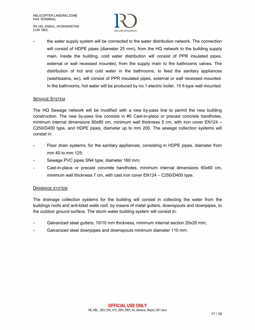
- the water supply system will be connected to the water distribution network. The connection
will consist of HDPE pipes (diameter 25 mm), from the HQ network to the building supply
main. Inside the building, cold water distribution will consist of PPR insulated pipes,
external or wall recessed mounted, from the supply main to the bathrooms valves. The
distribution of hot and cold water in the bathrooms, to feed the sanitary appliances
(washbasins, wc), will consist of PPR insulated pipes, external or wall recessed mounted.
In the bathrooms, hot water will be produced by no.1 electric boiler, 15 lt-type wall mounted.
SEWAGE SYSTEM
The HQ Sewage network will be modified with a new by-pass line to permit the new building construction. The new by-pass line consists in #5 Cast-in-place or precast concrete handholes, minimum internal dimensions 80x80 cm, minimum wall thickness 5 cm, with iron cover EN124 – C250/D400 type, and HDPE pipes, diameter up to mm 200. The sewage collection systems will consist in:
- Floor drain systems, for the sanitary appliances, consisting in HDPE pipes, diameter from
mm 40 to mm 125;
- Sewage PVC pipes SN4 type, diameter 160 mm;
- Cast-in-place or precast concrete handholes, minimum internal dimensions 60x60 cm,
minimum wall thickness 7 cm, with cast iron cover EN124 – C250/D400 type.
DRAİNAGE SYSTEM
The drainage collection systems for the building will consist in collecting the water from the buildings roofs and anti-blast walls roof, by means of metal gutters, downspouts and downpipes, to the outdoor ground surface. The storm water building system will consist in:
- Galvanized steel gutters, 10/10 mm thickness, minimum internal section 20x20 mm;
- Galvanized steel downpipes and downspouts minimum diameter 110 mm.
HELICOPTER LANDING ZONE PAX TERMINAL RS HQ, KABUL, AFGHANISTAN CUR 1803
OFFICIAL USE ONLY HB_KBL_1803_035_010_GEN_REP_A4_General_Report_R01.docx
18 / 35
8.3 VALUE ENGINEERING (VE)
The design solution has been deducted from a Value Engineering study in order to fulfil SoW requirements, operational demands and existing constrains through MMRs.
The space around the current HQ RS HLZ is limited, further, the HLZ is not part of NATO lease agreement with GIRoA and thus any modification to the sports fields or its walls have been avoided.
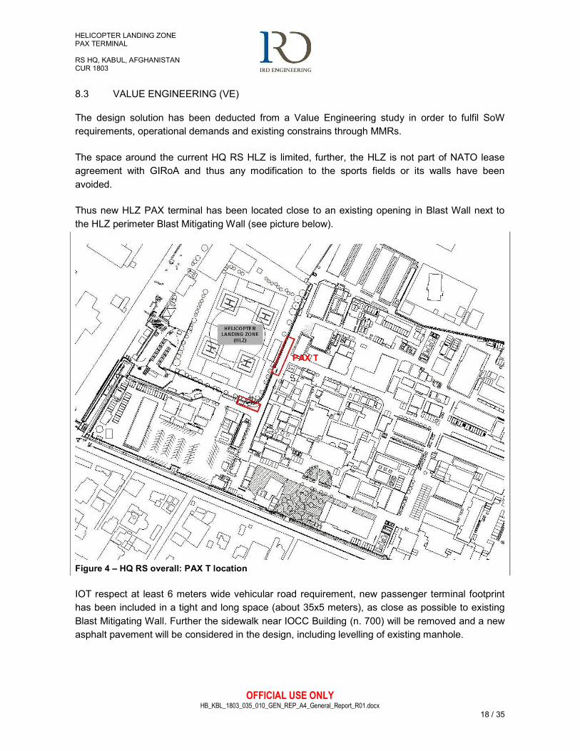
Thus new HLZ PAX terminal has been located close to an existing opening in Blast Wall next to the HLZ perimeter Blast Mitigating Wall (see picture below).
Figure 4 – HQ RS overall: PAX T location
IOT respect at least 6 meters wide vehicular road requirement, new passenger terminal footprint has been included in a tight and long space (about 35x5 meters), as close as possible to existing Blast Mitigating Wall. Further the sidewalk near IOCC Building (n. 700) will be removed and a new asphalt pavement will be considered in the design, including levelling of existing manhole.
PAX T
HELICOPTER LANDING ZONE PAX TERMINAL RS HQ, KABUL, AFGHANISTAN CUR 1803
OFFICIAL USE ONLY HB_KBL_1803_035_010_GEN_REP_A4_General_Report_R01.docx
19 / 35
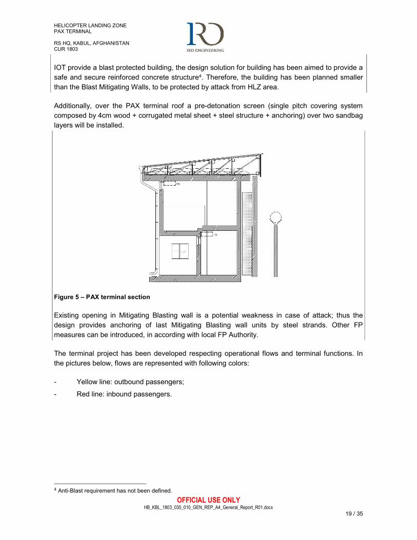
IOT provide a blast protected building, the design solution for building has been aimed to provide a safe and secure reinforced concrete structure4. Therefore, the building has been planned smaller than the Blast Mitigating Walls, to be protected by attack from HLZ area.
Additionally, over the PAX terminal roof a pre-detonation screen (single pitch covering system composed by 4cm wood + corrugated metal sheet + steel structure + anchoring) over two sandbag layers will be installed.
Figure 5 – PAX terminal section
Existing opening in Mitigating Blasting wall is a potential weakness in case of attack; thus the design provides anchoring of last Mitigating Blasting wall units by steel strands. Other FP measures can be introduced, in according with local FP Authority.
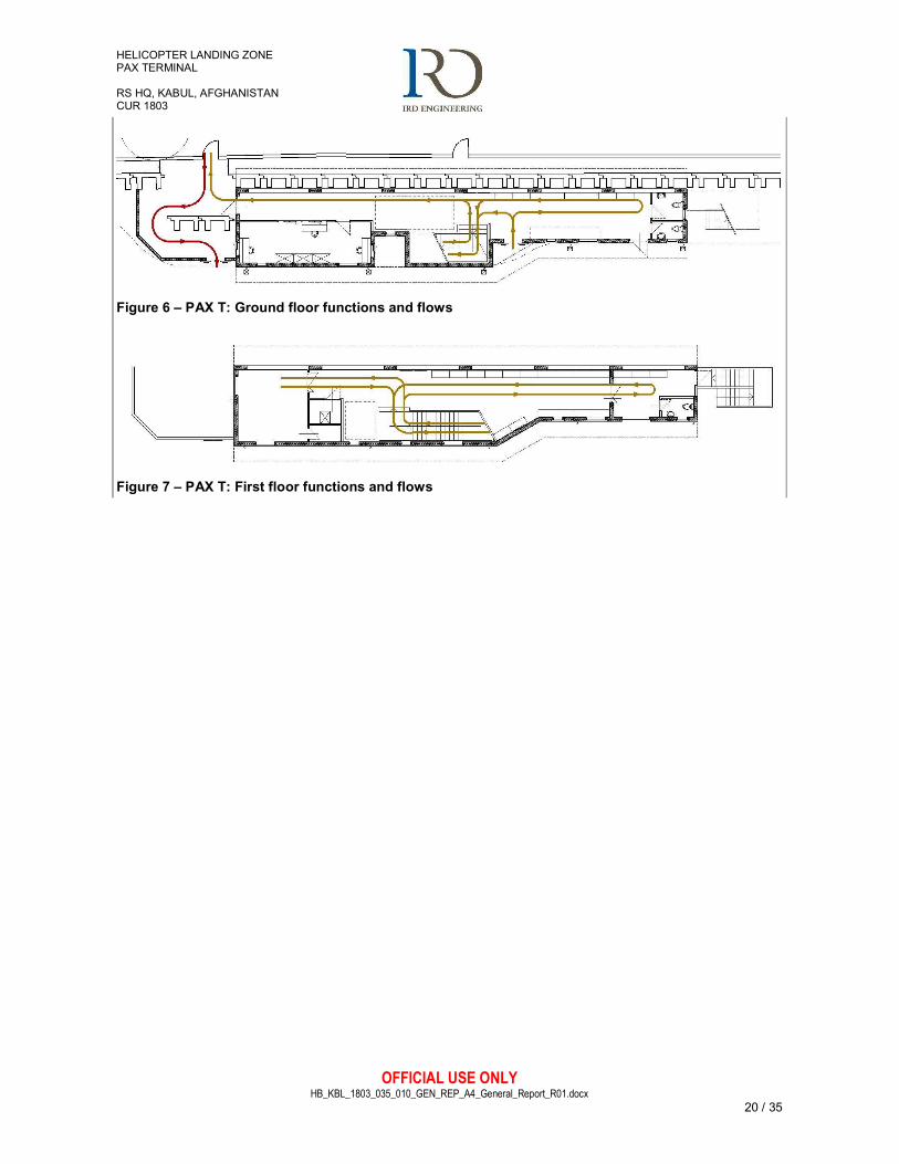
The terminal project has been developed respecting operational flows and terminal functions. In the pictures below, flows are represented with following colors:
- Yellow line: outbound passengers;
- Red line: inbound passengers.
4 Anti-Blast requirement has not been defined.
HELICOPTER LANDING ZONE PAX TERMINAL RS HQ, KABUL, AFGHANISTAN CUR 1803
OFFICIAL USE ONLY HB_KBL_1803_035_010_GEN_REP_A4_General_Report_R01.docx
20 / 35
Figure 6 – PAX T: Ground floor functions and flows
Figure 7 – PAX T: First floor functions and flows
HELICOPTER LANDING ZONE PAX TERMINAL RS HQ, KABUL, AFGHANISTAN CUR 1803
OFFICIAL USE ONLY HB_KBL_1803_035_010_GEN_REP_A4_General_Report_R01.docx
21 / 35
9. PROTECTED WATCH TOWER DESIGN
The design proposes realization of new Protected Watch Tower (PWT) capable of guarantee direct visibility of flights operations and Aerostat balloon (PTDS) in order to ensure safe control flights operations.
9.1 ARCHITECTURE SOLUTIONS
The PWT will be located in its current location and it will house n. 3 personnel in first floor Control cabin of about 18 sq. m.
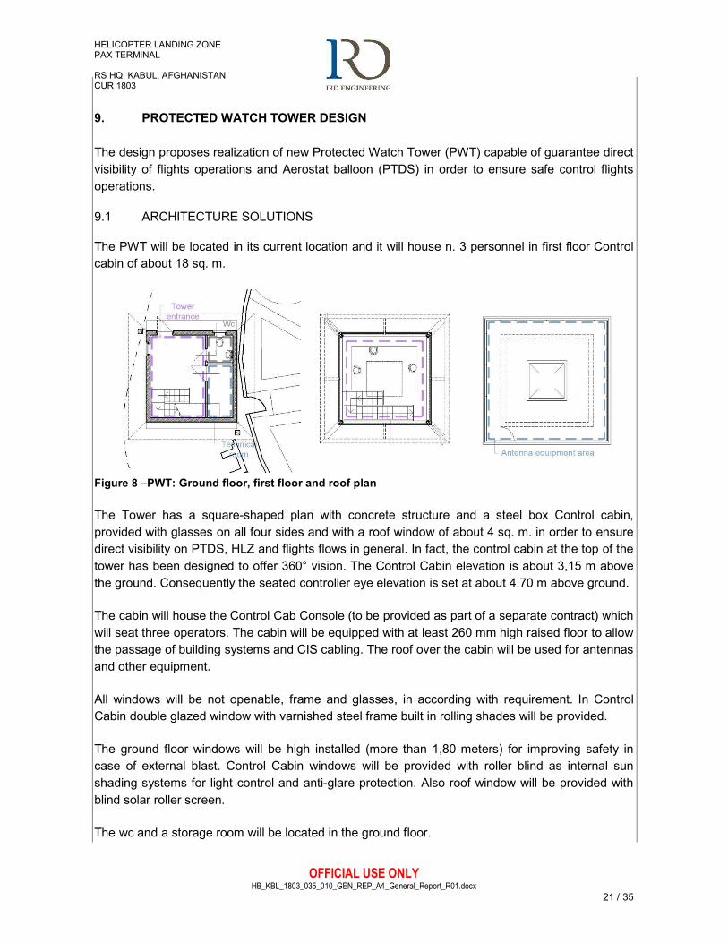
Figure 8 –PWT: Ground floor, first floor and roof plan
The Tower has a square-shaped plan with concrete structure and a steel box Control cabin, provided with glasses on all four sides and with a roof window of about 4 sq. m. in order to ensure direct visibility on PTDS, HLZ and flights flows in general. In fact, the control cabin at the top of the tower has been designed to offer 360° vision. The Control Cabin elevation is about 3,15 m above the ground. Consequently the seated controller eye elevation is set at about 4.70 m above ground.
The cabin will house the Control Cab Console (to be provided as part of a separate contract) which will seat three operators. The cabin will be equipped with at least 260 mm high raised floor to allow the passage of building systems and CIS cabling. The roof over the cabin will be used for antennas and other equipment.
All windows will be not openable, frame and glasses, in according with requirement. In Control Cabin double glazed window with varnished steel frame built in rolling shades will be provided.
The ground floor windows will be high installed (more than 1,80 meters) for improving safety in case of external blast. Control Cabin windows will be provided with roller blind as internal sun shading systems for light control and anti-glare protection. Also roof window will be provided with blind solar roller screen.
The wc and a storage room will be located in the ground floor.
HELICOPTER LANDING ZONE PAX TERMINAL RS HQ, KABUL, AFGHANISTAN CUR 1803
OFFICIAL USE ONLY HB_KBL_1803_035_010_GEN_REP_A4_General_Report_R01.docx
22 / 35
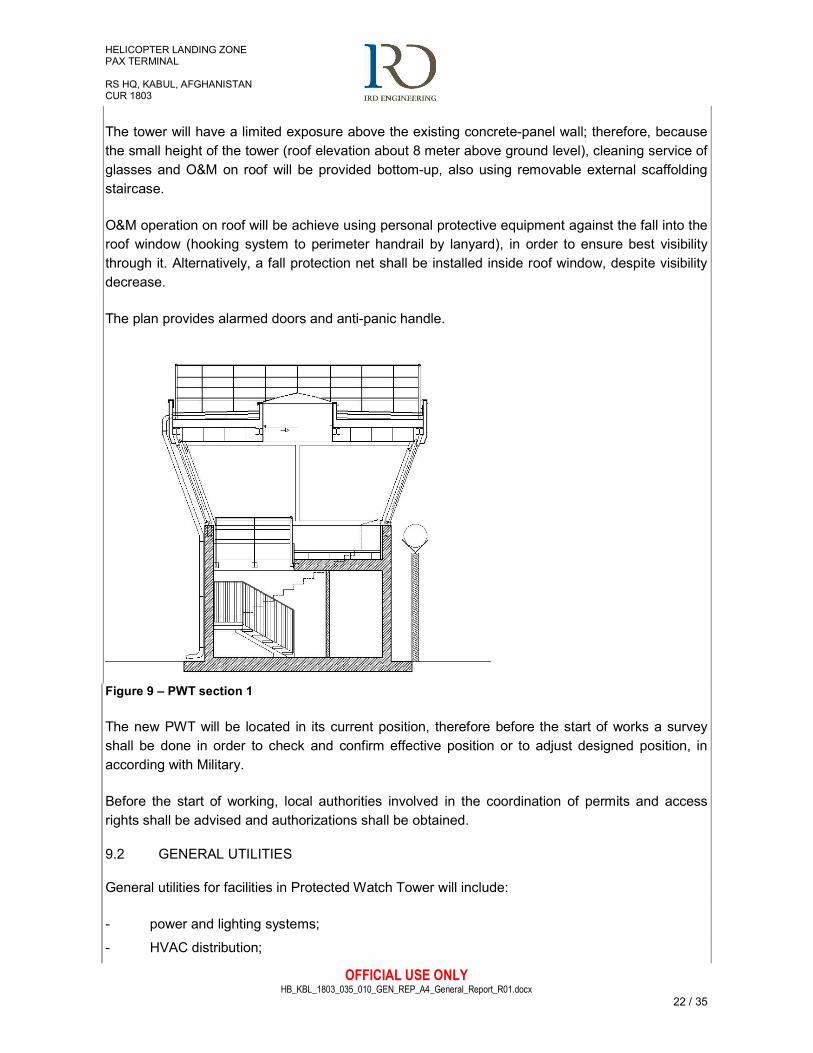
The tower will have a limited exposure above the existing concrete-panel wall; therefore, because the small height of the tower (roof elevation about 8 meter above ground level), cleaning service of glasses and O&M on roof will be provided bottom-up, also using removable external scaffolding staircase.
O&M operation on roof will be achieve using personal protective equipment against the fall into the roof window (hooking system to perimeter handrail by lanyard), in order to ensure best visibility through it. Alternatively, a fall protection net shall be installed inside roof window, despite visibility decrease.
The plan provides alarmed doors and anti-panic handle.
Figure 9 – PWT section 1
The new PWT will be located in its current position, therefore before the start of works a survey shall be done in order to check and confirm effective position or to adjust designed position, in according with Military.
Before the start of working, local authorities involved in the coordination of permits and access rights shall be advised and authorizations shall be obtained.
9.2 GENERAL UTILITIES
General utilities for facilities in Protected Watch Tower will include:
- power and lighting systems;
- HVAC distribution;
HELICOPTER LANDING ZONE PAX TERMINAL RS HQ, KABUL, AFGHANISTAN CUR 1803
OFFICIAL USE ONLY HB_KBL_1803_035_010_GEN_REP_A4_General_Report_R01.docx
23 / 35
- water, sewer (in toilet) and drainage systems;
- CIS system, including connection with Fire Department Building (n. 712);
- Access control and CCTV system.
Predispositions, wiring and connections for power and mechanical systems are included. Connection to local power system, and in general with all local systems, will be complied with Military instructions.
9.2.1 General
For CIS, CCTV, Access control and other auxiliary and special systems only the conduits (ducting, cable treys and other ancillary civil works) will be considered in the design; cables, racks and other active devices will be provided by Military. PWT will be located in an area containing some underground existing GUs (water and sewage systems5). Existing system will be intercepted and a new path will be defined along the road, outside building footprint. Refer to underground utilities map for Tower excavation and general utilities connections (and detours of networks). Connection to local systems will be complied with Military instructions. Before the start of works a soil survey should be done to consider depth of existing ducts and to prevent interference with existing Wall foundation. Furthermore, IOT prevent any damage to underground Gus, excavation will be processed manually and through small digging vehicles.
9.2.2 Electrical, Auxiliary And Special Systems
POWER SUPPLY
The building will be fed by the camp power network, through LV power supply cables installed in Ø160 HDPE underground ducts. Electric handholes shall be provided before the cables entrance to the building and wherever required. Power requirement of the facility is estimated as 30 kW, taking in consideration appropriate diversity factors for different systems. To assure the necessary back up power supply of the no break loads, an UPS (20 kVA) shall be installed.
UNINTERRUPTED POWER SUPPLY
No.1 20 kVA Uninterrupted Power Supply (UPS) System shall be provided, operating time 15’, which will feed all no break loads. In details the following items will be fed by the UPS:
- Workstation power sockets (for computers, screens, some printers);
- CIS devices;
- Fire alarm systems;
- Access Control Systems;
- Security systems.
5 Underground Gus relief based on available underground utilities map. On-site survey must be done IOT relieve real depth and effective position of GUs.
HELICOPTER LANDING ZONE PAX TERMINAL RS HQ, KABUL, AFGHANISTAN CUR 1803
OFFICIAL USE ONLY HB_KBL_1803_035_010_GEN_REP_A4_General_Report_R01.docx
24 / 35
UPS systems will not feed the lighting systems. On-Line Uninterruptible Power Source (UPS) will comply with applicable IEC / EN standards (IEC/EN 62040-1 & 60950 for performance and safety, 62040-3 for design, 60146 and ISO 9001 for manufacturing, 61000-2, 4, 6 & 62040-2 for EMC immunity & emissions).
PANELBOARDS AND POWER DISTRIBUTION
The building will be provided with a Main Electric Panel Board (MPB), which will be located at the Ground Floor. Only 230/400 V, 50 Hz European Standards shall be provided. Panel board feeder protection shall be with single, 3 pole and 4 pole circuit breakers with thermal over current and magnetic short circuit releases. All branch circuit protection up to and including 63 A shall be with miniature circuit breakers. For circuit protection bigger than 63 A rating, molded case circuit breakers will be used. The main and secondary power distribution LV cables shall be installed in wall mounted PVC trays.
INDOOR LIGHTING
Ceiling mounted LED lighting fixtures will be generally used throughout the tower. Illumination levels shall conform to EN 12464-1:2011 Light and lighting - Lighting of work places - Part 1: Indoor work places. Lighting level intensities of all spaces will be calculated by professional lighting calculations programs. Lighting switches shall be rated 10A, 230V, 50Hz. Wiring terminals shall be of the screw type or of the solderless pressure type having suitable conductor release arrangement. Lighting switches shall be installed 120 cm above finished floor (AFF), unless otherwise noted. Lighting level calculations shall be submitted during the following submittals. Throughout the facility lighting fixtures with built-in power-pack units, rechargeable batteries and battery charging device will be provided, for the emergency lighting.
EMERGENCY LIGHTING
Emergency lighting shall be provided in all rooms, corridors, stairs and passageways leading to an exit. Utility spaces will be equipped with emergency lighting, in regard of the importance of the room. Emergency lighting shall be provided for a period of 1 hour in the event of failure of normal lighting. Initial average illumination shall not be less than 10 lux and a minimum of 1 lux at any point measured along the path of egress at floor level. In general, emergency lighting units shall be located inside the regular lighting fixtures with built-in power-pack units, rechargeable batteries and battery charging device. The power pack will automatically transfer the supply to stand-by source during failure of normal power. Batteries shall be suitable to operate at –5 to +60 degrees C ambient temperature. LED charging indicator lamp and test switch shall be provided in the lighting fixture for easy recognition of emergency lighting fixture and allowing monitoring and testing of power packs by authorized personnel.
EXIT LIGHTS
All exit doors and escape routes shall be provided with (Sign or White Letters on Green Background) EXIT signs. Exit lights shall be provided with “EXIT” signs not less than 15.2 cm. (6”)
HELICOPTER LANDING ZONE PAX TERMINAL RS HQ, KABUL, AFGHANISTAN CUR 1803
OFFICIAL USE ONLY HB_KBL_1803_035_010_GEN_REP_A4_General_Report_R01.docx
25 / 35
high. Exit lights shall have vinyl coated aluminum or painted metal housing with translucent plastic face shield and “EXIT” sign illuminated with LED lamps, maintenance free “gel cell electrolyte” type pure lead battery (6V), charger, low-voltage-disconnect, push-to-test switch, and charging and battery failure indicators and shall be suitable for 230V, 50Hz operation. Emergency run time shall be 1 hour, minimum. Depleted battery recharging time shall be 12 hours.
OUTDOOR LIGHTING
LED lighting fixtures, water-resistant type, on steel poles or wall mounted, will be installed to light up the area around the building. These lights shall be turned on/off from the MPB. Obstruction Lighting system wil be installed on the Tower roof.
RECEPTACLE OUTLETS
Each workplace will be provided with 4 (four) single phase, 230V, 10/16A, 50 Hz, grounded type electric outlets, of which 3 (four) will be No Break (UPS powered), different color (red). All single phase receptacle outlets shall be P30 Schuko type. These outlets shall be wall or floor mounted (in dedicated floorboxes). Regular, single phase, 230V, 10/16A, 50 Hz, grounded type convenience receptacle outlets shall be provided in all rooms. All single phase receptacle outlets shall be P30 Schuko type. In the utility rooms, similar receptacles shall be surface mounted and weather-proof type. Receptacles in wet areas (toilet) shall be provided with cover plates for extended user safety. Standard outlet installation height shall be 45 cm above finished floor (AFF).
POWER DISTRIBUTION AND WIRING
In the rooms, all wiring for receptacle outlets shall be installed in PVC conduits wall mounted, floor recessed, in falce ceiling or under raised floor. All wiring for lighting systems shall be installed in PVC conduits wall, under raised floor or ceiling mounted. Wiring for main power provision and mechanical equipment requirements shall be installed in PVC cable trays and/or PVC conduits wall, under raised floor or ceiling mounted.
FIRE DETECTION AND ALARM SYSTEMS6
A new local fire alarm system shall be provided and installed throughout the facility in conformance with EN 54 and NFPA 72. Fire alarm system shall be backed-up by the Uninterruptible Power Source (UPS) for continuous and reliable fire safety operations. Fire alarm initiating and signalling devices shall be as follows.
- Manual break-glass type fire alarm stations located in accordance with quoted standards,
surface mounted, double action pull type.
- 120 dB Alarm horns with strobe lights, as required.
6 Only the conduits (ducting, cable treys and other ancillary civil works) will be considered in the design; cables, racks and other active devices will be provided by Military.
HELICOPTER LANDING ZONE PAX TERMINAL RS HQ, KABUL, AFGHANISTAN CUR 1803
OFFICIAL USE ONLY HB_KBL_1803_035_010_GEN_REP_A4_General_Report_R01.docx
26 / 35
- Two red coloured rotating flashing lights shall be provided on opposite roof corners for
visible fire alarm notification.
The Fire Alarm Panel will be installed in the Control cabin, first floor, and will be able to do
ACCESS CONTROL AND INTRUDER DETECTION SYSTEMS 7
Electronic card reading systems will be provided for the external door for controlled access into the facility. The emergency exit will be automatically unlocked in case of emergency by the Fire Alarm Panel board. Dedicated conduit/cable tray systems shall be provided throughout the facility for the IDS and the access control systems.
COMMUNICATION AND INFORMATION SYSTEMS (CIS) 8
CIS outlets shall be provided for each work station to satisfy CIS requirements. The outlets shall be wall mounted or shall be installed in floorboxes or under raised floor. Empty conduit/cable tray systems shall be provided throughout the Tower to allow subsequent wiring (By Others) for CIS Ethernet and telephone outlets. Conduits, cable trays or cable trunking shall be designed for star topology wiring. The conduit/cable tray systems shall be separated from the ones dedicated to other power or signal systems. The connection to the camp CIS main distribution will consist in undrground HDPE Ø110 mm ducts, with warning tape on the top of the trench (minimal depht of the top pipe 1.0 mt from the surface level), and cast in place concrete handholes (0.60x0.60 mt).
CCTV SYSTEM (PREARRANGEMENTS ONLY)
For this systems only the prearrangements (trays, ducts and boxes) will be installed.
LIGHTNING PROTECTION
A Lightning Protection System will be provided for the facility, in conformance with EN 62305, with roof mounted copper/iron arrestor rods, connecting copper/iron roof conductors, copper/iron down conductors with test terminals and grounding rods.
GROUNDING
Except where specifically indicated otherwise, all exposed on-current carrying metallic parts of electrical equipment, metallic raceway systems, cable trays and neutral conductor of the wiring system shall be grounded.
9.2.3 Mechanical Systems
7 Only the conduits (ducting, cable treys and other ancillary civil works) will be considered in the design; cables, racks and other active devices will be provided by Military. 8 Only the conduits (ducting, cable treys and other ancillary civil works) will be considered in the design; cables, racks and other active devices will be provided by Military.
HELICOPTER LANDING ZONE PAX TERMINAL RS HQ, KABUL, AFGHANISTAN CUR 1803
OFFICIAL USE ONLY HB_KBL_1803_035_010_GEN_REP_A4_General_Report_R01.docx
27 / 35
HVAC DİSTRİBUTİON
The heating, ventilation and air conditioning systems are illustrated in the project drawings and identified as follows:
- independent heating-cooling system for cabin control of the Tower; air conditioning system
shall consist in mono split heat pumps with inverter power control (power 7.1 kW cooling,
and 8.0 kW heating). The indoor units will be floor-standing, the outdoor units (power 11
kW) will be wall mounted outdoor at ground floor.
- The bathroom will be equipped with electric fan heater – (heating power 1000W).
- Air exhaust system for bathroom, consisting in n. 1 electrical fan 100 m3/h; the system will
comprehend n. 1 external circular ventilation grille - diameter 125 mm, and n. 1 transfer
grille door mounted - dimensions 200x100 mm.
For the condensate water dispersion, the collected water will be conveyed to the dispersant handhole system, composed by n. 2 dispersant handholes made of ring loser precast concrete units.
WATER DİSTRİBUTİON SYSTEM
The HQ Water distribution network will be modified with a new by-pass line to permit the new building construction. The new by-pass line consists in #3 Cast-in-place or precast concrete handholes, minimum internal dimensions 60x60 cm, minimum wall thickness 5 cm, with iron cover EN124 – C250/D400 type, and HDPE pipes, diameter up to mm 125. The building toilet will be served by supply water and hot water production and distribution systems with the following features:
- the water supply system will be connected to the water distribution network. The connection
will consist of HDPE pipes (diameter 25 mm), from the HQ network to the building supply
main. Inside the building, cold water distribution will consist of PPR insulated pipes,
external or wall recessed mounted, from the supply main to the bathrooms valves. The
distribution of hot and cold water in the bathrooms, to feed the sanitary appliances
(washbasins, wc), will consist of PPR insulated pipes, external or wall recessed mounted.
In the bathrooms, hot water will be produced by no.1 electric boiler, 15 lt-type wall mounted.
SEWAGE SYSTEM
The HQ Sewage network will be modified with a new by-pass line to permit the new building construction. The new by-pass line consists in #3 Cast-in-place or precast concrete handholes, minimum internal dimensions 80x80 cm, minimum wall thickness 5 cm, with iron cover EN124 –
HELICOPTER LANDING ZONE PAX TERMINAL RS HQ, KABUL, AFGHANISTAN CUR 1803
OFFICIAL USE ONLY HB_KBL_1803_035_010_GEN_REP_A4_General_Report_R01.docx
28 / 35
C250/D400 type, and HDPE pipes, diameter up to mm 200. The sewage collection systems will consist in:
- Floor drain systems, for the sanitary appliances, consisting in HDPE pipes, diameter from
mm 40 to mm 125;
- Sewage PVC pipes SN4 type, diameter 160 mm;
- Cast-in-place or precast concrete handholes, minimum internal dimensions 60x60 cm,
minimum wall thickness 7 cm, with cast iron cover EN124 – C250/D400 type.
DRAİNAGE SYSTEM
The drainage collection systems for the building will consist in collecting the water from the buildings roofs, by means of outlets, downspouts and downpipes, to the outdoor ground surface. The storm water building system will consist in:
- Outlet in roof floor, minimum diameter 110 mm;
- Galvanized steel downpipes and downspouts minimum diameter 110 mm.
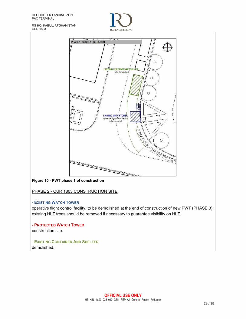
9.3 PHASES OF CONSTRUCTION
The design provides the removal of existing Watching Tower and Containers, including wall continuity refurbishment, GUs rearrangement, local pavement repair and other ancillary works.
During the construction of new Protected WT, existing Watching Tower will be relocated close to its current position, in order to guarantee operative flight control during the works. Therefore, existing Control tower will be temporary relocated and existing containers and other facilities will be demolished in order to allow the construction of new Protected WT in its current location. The suggested phases of construction are shown below.
PHASE 1 - CURRENT SITUATION
- EXISTING CONTAINER AND SHELTER to be demolished, in order to relocate existing Watch Tower.
- EXISTING WATCH TOWER operative flight control facility, to be relocated in order to build new PWT in its location.
HELICOPTER LANDING ZONE PAX TERMINAL RS HQ, KABUL, AFGHANISTAN CUR 1803
OFFICIAL USE ONLY HB_KBL_1803_035_010_GEN_REP_A4_General_Report_R01.docx
29 / 35
Figure 10 - PWT phase 1 of construction
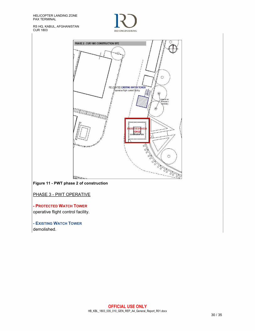
PHASE 2 - CUR 1803 CONSTRUCTION SITE
- EXISTING WATCH TOWER operative flight control facility, to be demolished at the end of construction of new PWT (PHASE 3); existing HLZ trees should be removed if necessary to guarantee visibility on HLZ.
- PROTECTED WATCH TOWER construction site.
- EXISTING CONTAINER AND SHELTER demolished.
HELICOPTER LANDING ZONE PAX TERMINAL RS HQ, KABUL, AFGHANISTAN CUR 1803
OFFICIAL USE ONLY HB_KBL_1803_035_010_GEN_REP_A4_General_Report_R01.docx
30 / 35
Figure 11 - PWT phase 2 of construction
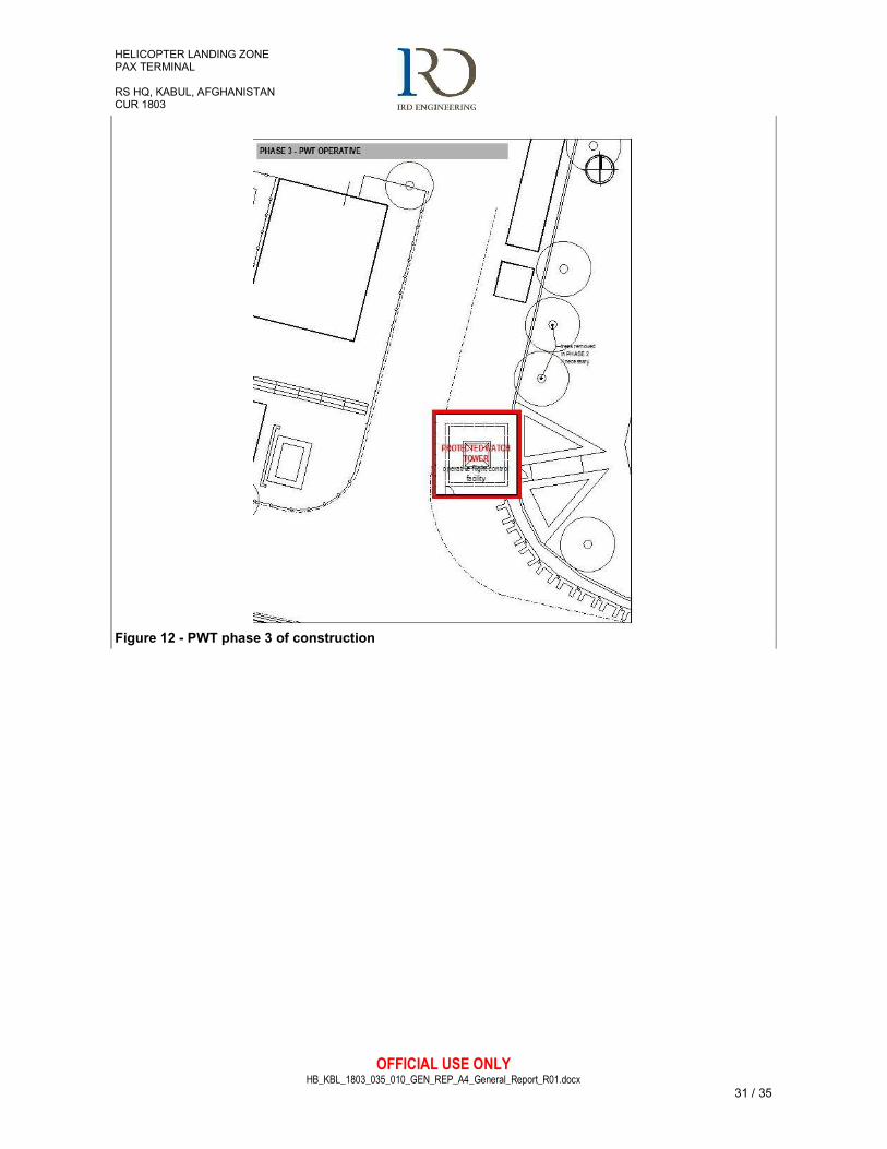
PHASE 3 - PWT OPERATIVE
- PROTECTED WATCH TOWER operative flight control facility.
- EXISTING WATCH TOWER demolished.
HELICOPTER LANDING ZONE PAX TERMINAL RS HQ, KABUL, AFGHANISTAN CUR 1803
OFFICIAL USE ONLY HB_KBL_1803_035_010_GEN_REP_A4_General_Report_R01.docx
31 / 35
Figure 12 - PWT phase 3 of construction

HELICOPTER LANDING ZONE PAX TERMINAL RS HQ, KABUL, AFGHANISTAN CUR 1803
OFFICIAL USE ONLY HB_KBL_1803_035_010_GEN_REP_A4_General_Report_R01.docx
32 / 35
9.4 VALUE ENGINEERING (VE)
The design solution has been deducted from a Value Engineering study in order to fulfil SoW requirements, operational demands and existing constrains through MMRs.
The HLZ is not part of NATO lease agreement with GIRoA and thus any modification to the sports fields or its walls have been avoided. Proposed current location is in proximity of the ECP, but the protection of the existing RC wall and the type of construction used will achieve improvement in protection.
Figure 13 – HQ RS overall: PWT location
At least 6 meters wide vehicular road will be provided.
IOT provide 360 degree view from Control cabin, the tower has been planned with a squared-plan steel box with glasses on all four sides. As required, glasses on the tower will be bullet proof and splinter protected from possible FOD when the helicopter landing.
To guarantee direct sight on the Aerostatic balloon (PTDS), a roof window will be provided.
P WT
ECP
HELICOPTER LANDING ZONE PAX TERMINAL RS HQ, KABUL, AFGHANISTAN CUR 1803
OFFICIAL USE ONLY HB_KBL_1803_035_010_GEN_REP_A4_General_Report_R01.docx
33 / 35
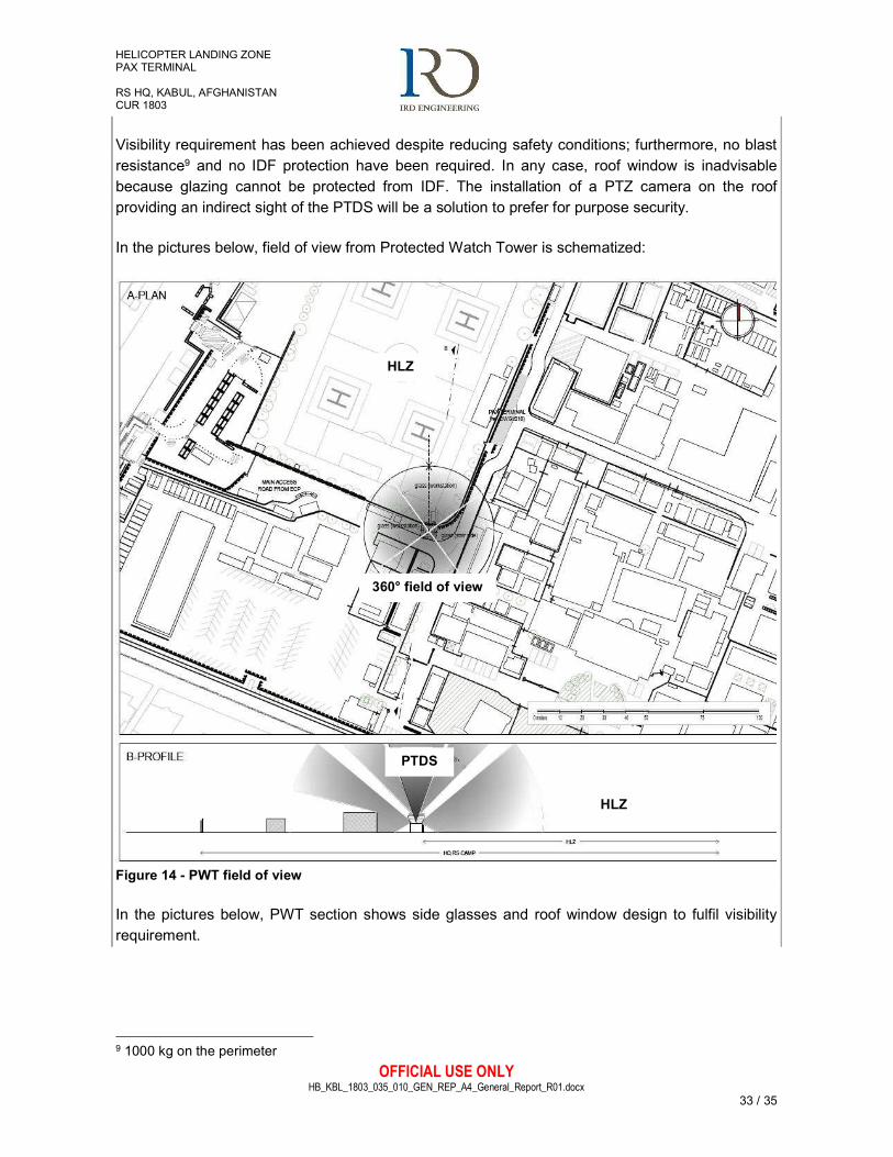
Visibility requirement has been achieved despite reducing safety conditions; furthermore, no blast resistance9 and no IDF protection have been required. In any case, roof window is inadvisable because glazing cannot be protected from IDF. The installation of a PTZ camera on the roof providing an indirect sight of the PTDS will be a solution to prefer for purpose security.
In the pictures below, field of view from Protected Watch Tower is schematized:
Figure 14 - PWT field of view
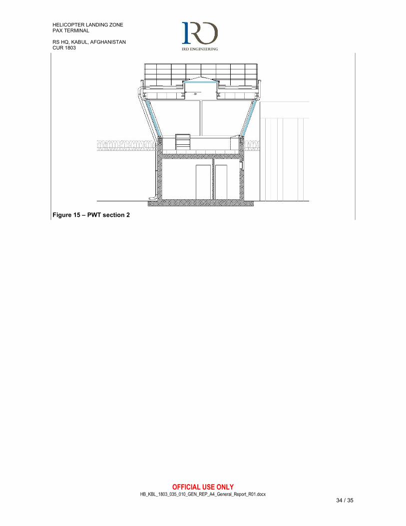
In the pictures below, PWT section shows side glasses and roof window design to fulfil visibility requirement.
9 1000 kg on the perimeter
360° field of view
HLZ
HLZ
PTDS
HELICOPTER LANDING ZONE PAX TERMINAL RS HQ, KABUL, AFGHANISTAN CUR 1803
OFFICIAL USE ONLY HB_KBL_1803_035_010_GEN_REP_A4_General_Report_R01.docx
34 / 35
Figure 15 – PWT section 2

HELICOPTER LANDING ZONE PAX TERMINAL RS HQ, KABUL, AFGHANISTAN CUR 1803
OFFICIAL USE ONLY HB_KBL_1803_035_010_GEN_REP_A4_General_Report_R01.docx
35 / 35
10. ANNEXES
The following documents are integrative and substantial parts of this preliminary design:
- #020 HB-KBL-1803-035-020-GEN-BOQ-A4- BOQ
- #030 HB-KBL-1803-035-030-GEN-WBS-A4- Time schedule
- #100 HB-KBL-1803-035-100-DWG-CRS-A1- Site location
- #110 HB-KBL-1803-035-110-DWG-CRS-A1- PAX TERMINAL - Survey and Photos
- #120 HB-KBL-1803-035-110-DWG-CRS-A1- P WATCH TOWER - Survey and Photos
- #200 HB-KBL-1803-035-200-DWG-MPL-A1- Site plan
- #205 HB-KBL-1803-035-205-DWG-MPL-A1- Overall
- #210 HB-KBL-1803-035-210-DWG-MPL-A1- PAX TERMINAL - Plans (Ground fl., First fl.)
- #212 HB-KBL-1803-035-212-DWG-MPL-A1- PAX TERMINAL - Roof plan and sect
- #220 HB-KBL-1803-035-220-DWG-MPL-A1- PAX TERMINAL – Elev and Sect
- #230 HB-KBL-1803-035-230-DWG-MPL-A1- PAX TERMINAL - Functions & Fluxes
- #240 HB-KBL-1803-035-240-DWG-GUS-A1- PAX TERMINAL - Power Supply and CIS
Connections
- #241 HB-KBL-1803-035-241-DWG-GUS-A1- PAX TERMINAL - Electrical and lighting
systems
- #242 HB-KBL-1803-035-242-DWG-GUS-A1- PAX TERMINAL - IDS, CCTV, Fire fighting
and PA systems
- #245 HB-KBL-1803-035-245-DWG-GUS-A1- PAX TERMINAL - Hydraulic / HVAC
distribution
- #246 HB-KBL-1803-035-246-DWG-GUS-A1- Interventions on GUs and Networks
- #250 HB-KBL-1803-035-250-DWG-MPL-A1- P WATCH TOWER – Plans
- #252 HB-KBL-1803-035-252-DWG-MPL-A1- P WATCH TOWER - Elev and sect
- #255 HB-KBL-1803-035-255-DWG-MPL-A1- P WATCH TOWER - Functions & Phases
- #260 HB-KBL-1803-035-260-DWG-GUS-A1- P WATCH TOWER - GUs mechanical
systems
- #262 HB-KBL-1803-035-262-DWG-GUS-A1- P WATCH TOWER - GUs electrical systems