h569 - av credenza 2u
TRANSCRIPT

H569 - AV Credenza 2UBeautifully executed video conferencing.

To reduce the risk of severe injury or death to persons, review these installation safety steps before proceeding:
Read all installation instructions for AV Credenza and AV Credenza
accessories before beginning any installation.
When supporting one or more displays using H544 Support Kit for AV
Credenza, always install the legs. Failure to support the weight of one or
more displays to the ground may result in injury.
Always use H570 Dual Display Kit for AV Credenza in combination with the
display supports and legs of H544 Support Kit. Failure to support the weight
of one or more displays to the ground may result in injury.
Anchor the AV Credenza to the wall for all installations.
Use the wood cleat provided for all installations.
Heavy duty SNAPTOGGLE brand wall anchors and 3/8” diameter screws are
provided for your convenience. While these wall anchors and screws are
suitable for many drywall and steel stud installations, a professional should
determine the best anchoring hardware and method for each specific
installation.
If you discover a defect, please contact [email protected].
1.
2.
3.
4.
5.
6.
2
7.

CAUTION: Shock Hazard
AV Credenza is an aluminum enclosure and therefore is electrically
conductive. Like all metal enclosures AV Credenza should be grounded
by a professional to reduce the risk of shock due to static electricity or
electrical shorts. AV Credenza features two ground lug locations for this
purpose. Bonding AV Credenza to a grounded PDU via these grounding
lugs is recommended.
3
grounding lug locations

IN THE BOX
TOOLS NEEDED
D E F G H I J K L M N O P
B C
Q R S
A
Level Tape Measure Power Drill Pen Stud Finder
4
AV Credenza 2U Body
Cable Chase
Camera Mount
SNAPTOGGLE Wall Anchors
Screw, 3/8”, 3” Long
Washer
Screw, M4, 12mm Long
Grommet Nut
Cable Tie Anchor
Velcro Strap Buckle
Velcro Strap Anchor
Velcro Strap
Cable Tie
Rackstuds™ Cap
Rackstuds™ Post
Rackstuds™ Washer
Hex Key, 3/32"
Hex Key, 5/32"
Screw, 1/4”-20, 5/16” Long
M
1 x
2 x
1 x
4 x
4 x
4 x
20 x
20 x
8 x
6 x
12 x
6 x
8 x
8 x
8 x
8 x
1 x
1 x
1 x
Fan Power Adapter1 x
Tie-down Strap 3 x
S T U
StepDrill Bit
3/4” SpadeDrill Bit

STEP 1Unpack. Box Top and Straps
Front Cover
Accessory Box
AV Credenza Body
Flanged Wing Nuts
French Cleat
Wood Screws and Washers
Shipping Pallet
Important Notes:
5
Two people should be involved in all unpacking and installation steps.
AV Credenza’s packaging is reuseable.
Unfasten the strap buckles and use them with tie-down straps included in the accessory box for subsequent shipments and relocations.
Do not discard the French cleat. Your French cleat arrives fastened to the shipping pallet. Remove the French cleat from the shipping pallet and use the cleat for your installation.
Handle the front cover with clean hands or gloves to prevent soiling the fabric wrap.

6
Important Notes: The following steps should be performed by a professional. Heavy-duty SNAPTOGGLE anchors, screws, and washers are provided for your convenience. A professional should determine if these fasteners are appropriate for your specific installation.
STEP 2Install the French cleat.
18”
12.75”
30”
36”AV Credenza Top Surface
AV Credenza Bottom Surface
Mark the center of the AV Credenza installation location, 30” above the finished floor.
1.
Mark your wall stud positions along the length of the cleat, 30” above the finished floor. For safety, we recommend you position the cleat to the wall so that two screws fasten to wall studs. The SNAPTOGGLE anchors provided are compatible with most steel wall studs.
2.
Starting at the center of the cleat, drill and install the first wall anchor (as shown on the next page).
3.
Fasten the cleat to the wall at this center position.4.
Use a level, then mark three additional mounting points using the cleat as your hole template.
5.
Install three additional wall anchors and fasten the cleat to those positions.
6.
x4 x4 x4
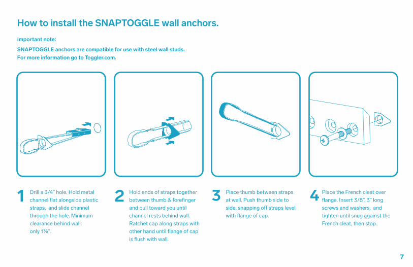
How to install the SNAPTOGGLE wall anchors.
Hold ends of straps together between thumb & forefinger and pull toward you until channel rests behind wall. Ratchet cap along straps with other hand until flange of cap is flush with wall.
2 Place thumb between straps at wall. Push thumb side to side, snapping o� straps level with flange of cap.
3
Place the French cleat over flange. Insert 3/8”, 3” long screws and washers, and tighten until snug against the French cleat, then stop.
4Drill a 3/4” hole. Hold metal channel flat alongside plastic straps, and slide channel through the hole. Minimum clearance behind wall:only 1⅞".
1
7
Important note:
SNAPTOGGLE anchors are compatible for use with steel wall studs. For more information go to Toggler.com.

8
STEP 3 (Optional)Install 19” rack components.
If desired, you can install your rack components before wall installation.
Place AV Credenza on its back on a tabletop.1.
Install the provided Rackstuds™(as shown on the next page).
2.
Slide components in place and fasten.3.
Rackstuds™ are provided for your convenience. AV Credenza is compatible with any conventional cage nut compatible with standard 19” rack. A professional should decide on the suitable installation hardware for your installation.
x8 x8 x8

How To Install and Remove Rackstuds™
Ensure you locate the first Rackstuds™ at the beginning of the “RU” space indicated by the thin section besides the hole. More info here http://en.wikipedia.org/wiki/Rack_unit
1. Insert the Rackstuds™ as shown (spring section toward the center of the rack) and at 45 degree.
2. Push the Rackstuds™ the rest of the way in so the spring clip latches on to the horizontal rail.
3. Mate the yellow washers. These must be fitted, as they create the opposing force required to lock your equipment to the rack. The washer will only go one way. If the stud was inserted correctly (the spring section toward the center of the rack), the washer will be the same.
4. Hang the 19” rack components on the first studs and apply pressure to the front face of the equipment while thumbing on the nuts(bottom ones first).
TO RELEASE: Reverse the above procedure by removing the TOP nuts first, then the bottom ones while supporting the gear.
5.
9
Rackstuds™ are NOT suitable for use in applications where the rack requires transportation when populated. The maximum equipment weight is 20kg (44lbs). By purchasing and using Rackstuds™ you agree, to the maximum extent permitted by law, that no party (including Rack Studs Limited) will have any liability to you whatsoever for any loss or damages (including any direct loss, loss of profit or anticipated profit, loss of revenue, loss of production, loss of goodwill or reputation, loss of use, loss of opportunity, loss of business, failure to realize anticipated savings, loss of any business opportunity and any other direct, indirect, special or consequential loss) resulting from the use or failure of Rackstuds™ or otherwise in respect of Rackstuds™ whether arising under contract, in tort, from breach of statutory duty or indemnity, or otherwise at law. Rack Studs Limited provides a very specific warranty (further detailed at rackstuds.com/certification) and to the maximum extent permitted excludes all other warranties (whether express or implied) and all or any liability. If you do not agree to these terms please immediately return Rackstuds™ product to the place of purchase for a full refund.
Do’s and Don’tsDO insert the Rackstuds™ as the spring section toward the center of the rack.DO use the washer. It performs an important function.DO remove the TOP nuts first then support your gear when removing the bottom nuts.DON’T leave your gear hanging on the two top studs.DON’T transport your rack unless your equipment is supported at the rear.
thin th
ickth
ickth
in

The back wall of AV Credenza features a VESA 100-compatible pattern of square holes. Use these holes, and the parts provided to mount small devices, mount VESA-compatible accessories, and route and tidy cabling.
10
STEP 4Install small devices and organize cables.
x12 x6 x8 x20 x6 x8x20
A
B
C

Three options to mount devices and organize cables.
11
Velcro StrapA Cable TieB VESA MountC
* VESA Bracket not included.
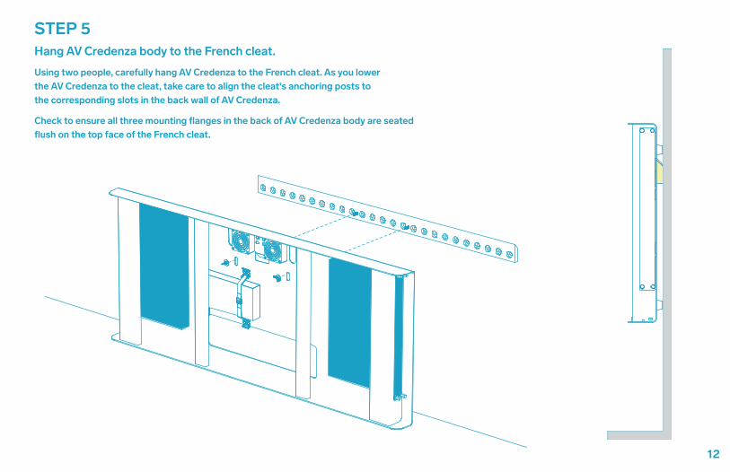
Using two people, carefully hang AV Credenza to the French cleat. As you lower the AV Credenza to the cleat, take care to align the cleat's anchoring posts to the corresponding slots in the back wall of AV Credenza.
Check to ensure all three mounting flanges in the back of AV Credenza body are seated flush on the top face of the French cleat.
12
STEP 5Hang AV Credenza body to the French cleat.

STEP 6Fasten AV Credenza to the French cleat.
13
x2
Important Safety Step:
Using the wingnuts provided, securely fasten the AV Credenza to the French cleat.

STEP 7Install camera mount.
Fasten the camera mount to your camera using the appropriate hardware.
A 1/4”-20, 5/16” long screw is provided for your convenience but may not be compatible with your camera.
¾”¾”
Select the installation position of the camera mount.
Fasten the mount.
14
x1
x1
x1
1.
2.
3.
42”

STEP 8Install the cable chase set and channel the display cables.
15
Tip: You may need to source long power cable and long HDMI cables to reach from the displays to the devices within AV Credenza.
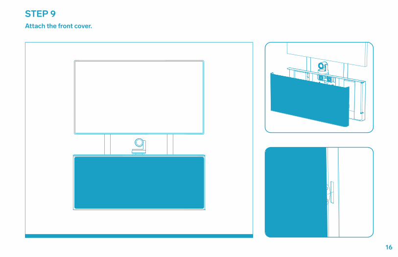
STEP 9Attach the front cover.
16