gv-gisftp.geovision.tw/ftp/kevin/user_manual/gv-gis/v2.1/v2.1... · 2010-06-24 · introduction 1...
TRANSCRIPT

User’s Manual V2.1 User’s Manual V2.1
GV-GIS

© 2010 GeoVision, Inc. All rights reserved. Under the copyright laws, this manual may not be copied, in whole or in part, without the written consent of GeoVision. Every effort has been made to ensure that the information in this manual is accurate. GeoVision is not responsible for printing or clerical errors. GeoVision, Inc. 9F, No. 246, Sec. 1, Neihu Rd., Neihu District, Taipei, Taiwan Tel: +886-2-8797-8377 Fax: +886-2-8797-8335 http://www.geovision.com.tw Trademarks used in this manual: GeoVision, the GeoVision logo and GV series products are trademarks of GeoVision, Inc. Windows and Windows XP are registered trademarks of Microsoft Corporation. April 2010

Contents Chapter 1 Introduction............................................................................1
..................................2
..................................3
..................................6
..................................6
..................................7
..................................9 Chap ................................10
................................10
................................13
................................13
................................14
................................16
................................16
................................17 ...............................18 ................................18 ................................18 ................................21
3.3.1 Colorful Mode...............................................................22 3.4 Playing Back GPS Tracks .........................................................23
3.4.1 Setting Playback Default Time Range..........................25 3.4.2 Showing the Time when a Host Passed by a Point......26 3.4.3 Showing GPS Tracks while Retrieving the Recordings 26
3.5 Tracking Multiple Hosts .............................................................27 3.5.1 Tracking Locations .......................................................27 3.5.2 Tracking Addresses......................................................28
3.6 Detecting Detours .....................................................................29 3.6.1 Defining a Detection Area ............................................29 3.6.2 Planning a Detection Route .........................................31
1.1 Features ....................................................1.2 System Requirements...............................1.3 Overview of GV-GIS..................................
1.3.1 Main Screen .................................1.3.2 Toolbar..........................................1.3.3 Event List......................................
ter 2 Getting Started.....................................
2.1 Installing the GV-GIS.................................2.2 Creating Host Accounts.............................
2.2.1 Creating a Mobile Host.................2.2.2 Creating a Fixed Host ..................
2.3 Connecting Hosts to the GV-GIS ..............2.3.1 Connecting a Mobile Host ............2.3.2 Connecting a Fixed Host ..............
Chapter 3 Tracking Operations for Mobile Hosts
3.1 Starting the Tracking Services...................3.2 Tracking Features .....................................3.3 Viewing Live Video....................................
i

3.7 Detecting Idle Speed.................................................................32 ................................34 ................................35 ................................36
Chap s.............................40 ................................40 ................................41 ................................41 ................................42 ................................43 nts...........................43 ................................45 ................................45 ................................48 ................................49 ................................49
50 ................................51 ................................52 ................................53 ................................55 ................................56
5.7 Applying Longitude and Latitude Positions on Fixed Hosts ......56 5.8 Monitoring GV-I/O Boxes ..........................................................58
Chapter 6 Event Log Browser..............................................................59 6.1 Opening the Event Log .............................................................61 6.2 Filtering the Event Log ..............................................................62 6.3 Backing up the Event Log .........................................................63 6.4 Printing the Event Log...............................................................65
Chapter 7 System Configurations .......................................................66 7.1 Layout Settings .........................................................................66
3.8 Detecting Over Speed...............................3.9 Viewing a List of Detection Settings..........3.10 Searching for Places and Devices ..........
ter 4 Monitoring Operations for Fixed Host
4.1 Starting the Monitoring Services ...............4.2 Monitoring Features ..................................
4.2.1 Fixed Host Icon ............................4.2.2 Camera Icon.................................4.2.3 Output Icon...................................
4.3 Detecting Motion and Input-Triggered Eve4.4 Retrieving Recorded Videos .....................
4.4.1 Instant Playback ...........................4.4.2 Remote ViewLog ..........................
Chapter 5 Advanced Operations .........................
5.1 Creating an E-Map ....................................5.1.1 Configuring E-Map Icon Settings .................................
5.2 Adding a Place ..........................................5.3 Saving a View ...........................................5.4 Getting Driving Directions .........................5.5 Self-Defining Event Colors ........................5.6 Showing Host Position on an Alarm Event
ii

7.2 Network Settings......................................................................67 ................................68 ................................69 ................................70 ................................71 ................................73 ................................73 ................................74 ................................74 ................................75 ................................75 ................................77
77 .................78
................................80
................................80
................................80
................................81
................................81
................................82 Chapter 13 Remote Viewing Using a Web Browser...........................84
13.1 Creating Web Accounts...........................................................84 13.2 Accessing the Web Interface ..................................................86 13.3 Accessing Monitoring Features...............................................88
13.3.1 Host Icon......................................................................88 13.3.2 Input and Output Icons.................................................89
13.4 Viewing Live Video from a Web Browser ................................90 13.5 Retrieving Recorded Videos from a Web Browser..................92 13.6 Accessing the Event Log from a Web Browser.......................94 13.7 Getting Driving Directions from a Web Browser......................95
7.3 Event Log Settings ....................................7.4 Remote ViewLog Settings.........................7.5 Alert Intervals ............................................
Chapter 8 Notification Settings............................
Chapter 9 Output Alerts ........................................
9.1 Adding Output Devices .............................9.1 Forcing Outputs of GV-GIS .......................9.2 Forcing Outputs of a Host .........................
Chapter 10 SMS Alerts..........................................
10.1 Setting SMS Server.................................10.2 Connecting to SMS Server......................10.3 Sending SMS ..........................................................................10.4 Inserting ID and Camera Name to Alert Messages
Chapter 11 E-Mail Alerts .......................................
11.1 Setting Mailbox........................................11.1.1 Setting up the mailbox ................11.1.2 Sending a Test E-Mail.................
11.2 Sending E-Mail ........................................
Chapter 12 Failover Support ................................
iii

Appendix…...............................................................................................96 ................................96 ................................96 ................................98
103 E. Specifications............................................................................104 F. Modifying Port Number for running GV-GIS on the same computer with GV-System ...............................................................................105
A. Dongle Options ...........................................B. Upgrading the GV-GIS Dongle ...................C. Installing the Internal USB Dongle..............D. Shortcut Keys ...........................................................................
iv

Introduction
1
Chapter 1 Introduction The GV-GIS is a GIS (Geographic Information Systmanagement system for GeoVision devices. The vehicle tracking and location verification remote
em) based central
ly from the GV-GIS is made possible by the GPS receiver installed in GV-Video Server and
peed) from the satellite, and through mobile internet connection (e.g. UMTS, EDGE, GPRS, GSM, etc) to transmit the GPS data to the GV-GIS. Besides real-time vehicle tracking, you can also monitor the location of cameras and the status of I/O devices from the DVR devices, without GPS functions.
GV-Compact DVR to constantly obtain the GPS data (vehicle coordinates and s
GV-Compact DVR+ GPS Reciever
GV-Video Server+ GPS Reciever
GIS E-MapGeo-GIS Central Management System
(GIS+ E-Map + Live Image)
Satellite
Mobile Hosts
Get GPS data from Satellite
Mobile Internet Connection, e.g. UMTS, EDGE, GPRS, GSM, etc.
Fixed Hosts
TCP/IP
GV-SystemGV-NVR
GV-IP Camera GV-Video Server GV-Compact DVRGV-I/O Box
Figure 1-1
1

1.1 Features • GIS central management system
hicle GPS coordinates
ehicle video image
, Microsoft Virtual Earth and user-defined maps support
s playback
• E-Map Support
• Motion and Input-triggered alert for fixed hosts
• Customized landmark (interested points) setting
• Integration with GV-I/O Box, GV-Video Server, GV-Compact DVR, GV-IP Camera, GV-System and GV-NVR
• GIS Web Interface for remote monitoring and tracking
• 500 vehicles tracking at one time
• Real-time ve
• Real-time v
• Google Maps
• GPS Track
• Detour Detection
• Idle Speed Detection
• Over Speed Detection
2

Introduction
1
1.2 System Requirements ystem req -GIS:
Standard Version
1. The minimum s uirements to run the GV
10 Mobile-Host Map Views
10 Mobile-Host Map Views with up to 10 Megapixel
Live Views
3 8 2-bit Windows XP / Vista / 7/ Server 200OS
64-bit Windows 7/ Server 2008
CPU Pentium 4, 3.0 GHz with HT Core 2 Quad 8300, 2.5 GHz
Memor B Dual Channels 2 x 1 GB Dual Channels y 2 x 512 M
Hard D required to install GV-GIS (Standard
isk The hard disk space
Version) must be at least 1 GB.
VGA NVIDIA GeForce 8600 GT / ATI Radeon X1650
DirectX 9.0c
Browser Internet Explorer 7.x
Software .Net Framework 3.5
Hardware External or Internal GV-GIS Dongle
Note: DirectX and .Net Framework can be found in the Software DVD.
3

Advanced Version (Up to 500 Mobile Hosts)
16 Mobile-H
16 Mobile-Host Map Views ost Map Views with up to 16 Megapixel
Live Views
3 P / Vista / 7 / Server 2008 2-bit Windows XOS
6 er 2008 4-bit Windows 7/ Serv
CPU Core i5-750, 2.67 GHZ Pentium 4, 3.0 GHz with HT
Memory hannels 2 x 1 GB Dual C
Hard Disk The hard disk space required to install GV-GIS (Advanced
east 1 GB. Version) must be at l
VGA NVIDIA GeForce 8600 GT / ATI Radeon X1650
DirectX 9.0c
Browser Internet Explorer 7.x
Software .Net Framework 3.5
Hardware External or Internal GV-GIS Dongle
Note: DirectX and .Net Framework can be found in the Software DVD.
Note: The minimum system requirements are collected by using the GV-IPCam 1.3M for test, and may vary based on connected IP device models.
4

Introduction
1
2. A GV-GIS dongle is required for the GV-GIS
The primary USB dongle provides the
software to work.
options of 1, 3, 5, and ehicle connections,
with the limit of 500
our sales representative the required number of vehicle d upon your
ments. Otherwise, you can upgrade your primary dongle later by following the instructions in Appendix B. Upgrading the GV-GIS Dongle.
s, External USB Dongle C Installing the Internal
USB Dongle.
Note:
1. For types of GV-GIS dongles, see Appendix A. Dongle Options.
2. For the Defog and Stabilizer functions on Live View, the GV-GIS dongle with AVP function is required.
10 vehicle connections. After first 10 vevery increment is 5 connectionsconnections in total.
Inform yconnections so the dongle can be delivererequire
The GV-GIS dongles come in two optionand Internal USB Dongle. See Appendix
5

1.3 Overview of GV-GIS Get yourself familiar with the Main Screen, Toolbar and Event List, as it will
u read further in the following sections.
1.3.1 Main Screen
Microsoft Virtual Earth is used as Map API (Application Program Interface) in this example.
help you when yo
Figure 1-2
No. Name Description
1 Host List Include these types of folders: Mobile Host List, Fixed Host List, Expended Markers, and New Map.
6

Introduction
1
2 NavigatiControls
om, look and move around. on
Use these to zo
3 Views Click these to display different views, including aerial
gery. images and street level ima
4 Map This area displays the trackquery results.
ing map, E-Map and
5 Overview Map This view shows the location of current map view.
6 Monitor s of video motion and
t the fixed host. See 4.3 triggered Events.
List Activate monitoring of eventinput trigger occurred aDetecting Motion and Input-
7 TrackingIndicator
Host Indicate the connected mobile hosts. Take the picture
for example. Three (3) mobile hosts are connecting to the GV-GIS while GV-GIS supports the maximum of 50 mobile hosts.
8 Event List See Event List later.
9 Toolbar oolbar later. See T
1.3.2 Toolbar
Figure 1-3
No. Name Description
1 Start/Stop Service Start or stop the GV-GIS services.
2 Start/Stop Web ServiceEnable or disable the access to GV-GIS’s Web interface.
3 System Configuration Configure the system. See Chapter 7 System Configurations.
4 Account Configure host accounts. See 2.2 Creating Host Accounts.
7

5 W uncounts for accessing
ce. See Chapter 13 Remote Viewing Using a Web Browser.
eb Acco t GV-GIS’s Web interfaConfigure user ac
6 Notification St to send notifications
ee 5.10 Notification Settings.
etting when it happens. SConfigure which even
7 I/O Devable I/O devices on your
. Local ice Control
Open the list of availsystem
8 Event ent List on the main
List Open or close the Evscreen.
9 Monitor List the Monitor List on the main
cting Motion and s.
Open or close screen. See 4.3 DeteInput-triggered Event
1 Br for log events. See Chapter 6 Event
ser. 0 Event Log owser
Log BrowSearch
1 for places and devices. See 3.9
Searching for Places and Devices. 1 Range Query
Search
12 Track List Track addresses of multiple mobile hosts in real time. See 3.5 Tracking Multiple Hosts.
13 Map Setting Configure the settings for E-Map icons. See 5.1 Creating an E-Map.
14 Up One Level Map Display the previous map.
15 Map Home Display the tracking map.
16 Down One Level Map Display the next map.
8
Introduction
1
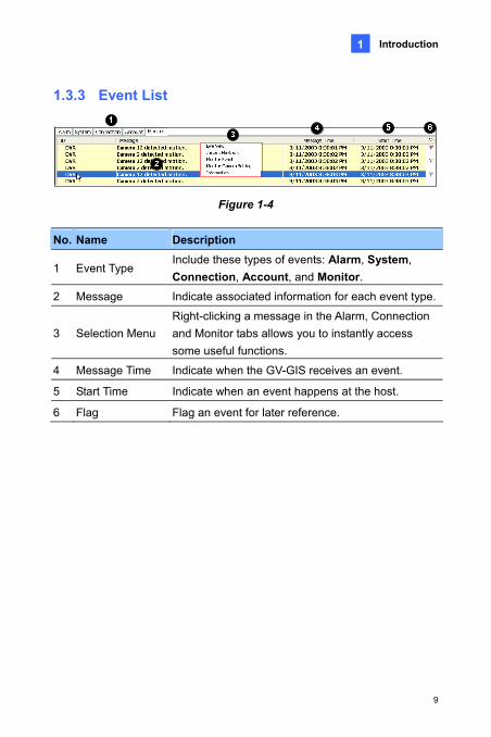
1.3.3 Event List
Figure 1-4
No. Name Description
1 Event Tys: Alarm, System,
and Monitor. pe
Include these types of eventConnection, Account,
2 Message ted information for each event type. Indicate associa
3 Selection Menu Right-clicking a message in the Alarm, Connection and Monitor tabs allows you to instantly access some useful functions.
4 Message Time Indicate when the GV-GIS receives an event.
5 Start Time Indicate when an event happens at the host.
6 Flag Flag an event for later reference.
9

Chapter 2 Getting Started
2.1 Installing the GV-GIS ver
and .Net Framework first. Follow the steps below to install those programs.
1. Insert the Software DVD to your computer. This window pops up automatically.
Before installing the GV-GIS, you need to install the USB dongle dri
Figure 2-1
2. To install USB dongle driver, select Install or Remove GeoVision GV-Series Driver, and click Install GeoVision USB Devices Driver.
3. To install .NET Framework, select Install Microsoft .NET Framework 3.5.
4. To install GV-GIS, Select Install GeoVision V2.1.0.0 GV-GIS System and follow the on-screen instructions.
10

Getting Started
2
5. The first-time user will be prompted for a License Agreement.
oVision products and you should apply for the license of the API by yourself in advance.” Read through the license terms before you click I understand and agree to continue.
Note “The license of API is excluded from Ge
Figure 2-2
6. From the “Please Select a Map API” drop-down list, select a Map API (Application Program Interface). For Google Maps, you need to sign up for an API key from Google website (http://code.google.com/apis/maps/signup.html), and enter the API key in the Please enter the map authorization key or license key field.
11

Figure 2-2
7. Click Submit to open the main screen.
Note:
3. Some GV-GIS features may not be available to your location depended on Maps API.
4. If you want to use the maps created by yourself, overwrite the files at :\GV-GIS folder\GIShtm-User, and select User Defined from the “Please Select a Map API” drop-down list.
5. If you are the paid-client of Google Maps, select Client from the “Please enter the map authorization key or license key” drop-down list; otherwise select Key.
12

Getting Started
2
2.2 Creating Host Accounts Create host accounts for the DVR devices you wishwith the GV-GIS. The GV-GIS su
to track and manage pports two types of hosts: Mobile Host
and Fixed Host. Mobile hosts refer to those devices equipped with GPS hicles, while fixed hosts refer to those without
.3, Figure 1-3). The ears.
lder if necessary.
host account.
Password for the host to log onto the GV-GIS.
TEL, Mobile, Address
llows you to set the minimal zoom level of the host icon on the map. For example, if you set it to 14, you can only see the host icon on the map when zooming in to the level 14 or above. Setting the level to 0 makes the host icon always visible regardless of zoom level.
After creating host accounts, click the Start/Stop Service button (No.1, Figure 1-3) on the toolbar to start the GV-GIS service. Meanwhile, hosts must be configured and connected to the GV-GIS. See Connecting Hosts to the GV-GIS later for how hosts can log onto the GV-GIS.
receivers and installed in veGPS functions and installed at fixed locations.
2.2.1 Creating a Mobile Host
1. On the toolbar, click the Account button (NoAccount window app
2. Click the Add A Group button to create a group fo
3. Click the Add A Subscriber button to create a
4. Assign ID and
5. Other information of the host such as Name,and E-Mail are optional entries.
6. The Visible Level in Map option a
13

2.2.2 Creating a Fixed Host
1. On the toolbar, click the Account button (No.3, Figure 1-3). The
p folder if necessary.
ost account.
lect a device type from
IP Address, Login ID e default
y port values if necessary.
the Update Information
Account dialog box appears.
2. Click the Add A Group button to create a grou
3. Click the Add A Fixed Host button to create a h
4. In the dialog box,
A. Name the host in the Host ID field and sethe Host Type drop-down list.
B. In the Connection Information section, typeand Password to log onto the host. Use thcommunication ports, or modif
C. In the Device Information section, click to request the numbebutton r of cameras and I/O modules
installed from the host.
tions to certain cameras, era Monitor Setting button
D. If you want to disable the monitoring funcclick the Cam . For details, see 4.3 Detecting Monitor and Input-Triggered Events.
E. For the Apply the Device’s GPS positions option, see 5.7 Applying Longitude and Latitude Positions on Fixed Hosts.
F. Subscriber Information and Note are optional entries
After creating host accounts, some hosts must be configured and connected to the GV-GIS. See Connecting Hosts to the GV-GIS later for how hosts can log onto the GV-GIS.
14

Getting Started
2
Figure 2-3
Note:
1. The Visible Level in Map option in the “Subscriber Information” section is to set the minimal zoom level of the host icon on the map. The same option in the “Device Information” section is to set the minimal zoom level of camera and I/O icons on the map. For details on the option, see step 6 in 2.2.1 Creating a Mobile Host.
2. The communication ports of DVR (Command Port 3388, Data Port 5611 and Log Port 5552) should match Control Center ports on that DVR.
15

2.3 Connecting Hosts to the GV-GIS You need to configure hosts in order to access the GV-GIS service remotely
from the GV-GIS, first make sure a s GPS function is UMTS) on the host
must be activated so that the GV-GIS can access the GPS data through the connectivity. For details on GPS and mobile internet connection, see GV-Video Server or GV-Compact DVR User’s Manual. 1. Open the configuration interface of the GV-Video Server or
GV-Compact DVR, and select GV-GIS.
through a network connection.
2.3.1 Connecting a Mobile Host
To perform the GPS tracking remotelyGPS receiver is connected to the mobile host and itactivated. Then, the mobile internet connection (e.g.
Figure 2-4
2. Select Activate Link.
3. Type IP address or domain name of the GV-GIS.
4. Keep Port number as default, or change it if necessary.
16

Getting Started
2
5. Type User Name and Password used to log onto the GV-GIS. These D and Password created on the GV-GIS. See
lished between the mobile host and GV-GIS, a : xxx” will be displayed at the
uration page.
ecting a Fixed Host
GV-System, GV-NVR: To establish the connection, activate the Control Center Service.
GV-Video Server, GV-Compact DVR, GV-IP Camera, GV-IP Speed Dome: It is not required to set up these fixed IP devices for connection.
entries must match ICreating Host Accounts earlier in this chapter.
6. Click Apply to start connection.
When the connection is estabmessage “Status: Connected. Connected Timebottom of the config
2.3.2 Conn
17

Chapter 3 Tracking Operations for Mobile Hosts
3.1 Starting the Tracking Services
s GPS-enabled, the host icon will automatically move to its correct location on the map.
3.2 Tracking Features On the map or the Mobile Host List, right-click the mobile host icon to have these tracking features:
You can track locations of mobile hosts in real time.
After the GV-GIS service is started, drag the mobile host icon to the map. Since the host i
Figure 3-1
18

Tracking Options for Mobile Hosts
3
Feature Description
Live View ideo. Display live view. See 3.3 Viewing Live V
Playback Play back the GPS tracks recorded at the mobile Tracks. host. See 3.4 Playing Back GPS
Send E-ma ail notification. See Chapter 11 E-Mail il Send an e-mAlerts.
Send SMS Message
Chapter 10 SMS Alerts.Send a SMS notification. See
Information Display the host information.
Configure of the mobile host, such as GV-Video Server and GV-Compact DVR. Link to the configuration interface
Remove M ap. arker Remove the host icon from the m
Track Mark aying at the center of the A yellow block similar isplayed on the map.
will stop the host tracking.
er Always keep the host icon stmap when the vehicle moves. to the following figure will be dClicking the yellow block
New-Map View Track the host in a separate window. See 3.5 Tracking Multiple Hosts.
Add to Track List Create a Track List to track multiple hosts. See 3.5 Tracking Multiple Hosts..
Map Event Setting
Configure detour, idle speed and over speed detection. See 3.6 Detecting Detours, 3.7 Detecting Idle Speed and 3.8 Detecting Over Speed.
Range Query Search for places and devices. See 3.9 Searching for Places and Devices.
19

Search the Nearest En
esired host or marker. The provide step-by-step
directions from the host to that target. Note that depending on Maps API, this feature may not be available for your location.
try Allow you to search for a dGV-GIS will display a route and
The blue line provides the possible route from the selected host to the target.
The window provides the estimated distance and step-by-step directions.
20

Tracking Options for Mobile Hosts
3
3.3 Viewing Live Video To view live video, right-click one host or camera icon and select Live View.
Figure 3-2
The controls on the Live View window:
No. Name Description
1 Change C ra of the same host. amera Switches to another came
2 Change Size
nges the size of the live video. The e video resolution set at
the host. Defog: Enhances image visibility. Stabilizer: Stabilizes live images. PIP View: Refers to Picture and Picture. You
can zoom in on the video. PAP View: Refers to Picture and Picture. You
can create a split video effect with multiple close-up views on the video.
Size: Chasize corresponds to th
3 Audio Accesses audio from the host.
4 Microphone Enables speaking to the host. A microphone must be installed properly in the computer.
21

5 Setting
settings. e for adjusting the image color
tion) and for decreasing the fogginess of e).
(Normaliza
Changes the audio and videoDefog settings ar
the image (Sampling Rang6
PTZ Activates the PTZ control.
7 Visual Automation
rent state of an electronic device, e.g. light ON, by clicking on its
hen
Allows you to change the cur
image directly. The function is only available wthe same function is set at the host.
8 Snapshot Takes the snapshot of the displayed live video. 9 Zoom Enlarges the video by selecting 1.0x, 2.0x and 3.0x.
are only available when the GV-GIS dongle with
Defog settings in
Note: The options belowAVP function is used:
Defog and Stabilizer options in the Change Size button; the Setting button.
3.3.1 Colorful Mode
You can enhance the coloring of live video to have more vivid and saturated images. Click the Configure button from the menu bar, select DirectDraw Configuration, select Use Colorful Mode, and restart the GV-GIS program for the mode to take effect.
22
Tracking Options for Mobile Hosts
3
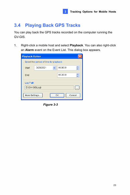
3.4 Playing Back GPS Tracks You can play back the GPS tracks recorded on the cGV-GIS.
omputer running the
1. Right-click a mobile host and select Playback. You can also right-click
an Alarm event on the Event List. This dialog box appears.
Figure 3-3
23

2. Specify the date and a period of time of the recorded tracks. Keep the default log path C:\GV-GIS\Log, or modify it if necessary. Then click OK. The Playback window appears.
4. Select Show Routes if you want each GPS track to be drawn as a solid line. Select Show Directions to display a direction icon for every GPS track in the map.
5. Select the Instant Playback button
Figure 3-4
3. Click the Play button to start.
if you want to retrieve recorded video from the mobile host. A valid ID, Password, IP address and Port number are required to log on to the host.
Note: For Instant Playback, the mobile host needs to grant the remote access from the GV-GIS by activating the Remote ViewLog function on itself. For detailed playback operations, see 4.4.1 Instant Playback.
24

Tracking Options for Mobile Hosts
3
3.4.1 Setting Playback Default Time Range
ve time for GV-GIS ack the same time length of GPS tracks.
1. Click the More Settings button on the Playback Option dialog box
(Figure 3-3). This dialog box appears.
Setting the default time range for playback can saoperators if they always play b
Figure 3-5
umber of minutes prior event was triggered.
etting effects the Start time in the Playback Option (Figure 3-3). 3. Set Total Playback Time to define the default total length that the
time in the Playback
4. Click OK. For example, if Pre-playback Time is set to 10 minutes and Total Playback Time is set to 30 minutes. When the message time of a selected Alarm event is at 11:30:00, the Start time will begin at 11:20:00 and End time will finish at 11:50:00.
Note: When the Playback is accessed by right-clicking a mobile host icon, the Start and End time are based on your current computer time instead of the message time of an Alarm event.
2. Set Pre-playback Time to define the default nto the Message Time when the selected AlarmThis s
playback will play. This setting effects the End Option (Figure 3-3).
25

3.4.2 Showing the Time when a Host
You can obtain the exact time when a host passed
Passed by a Point
by a point. To do this, select Show Rout, click a point along the route and select Show the time
ow will appear showing the ost passed by the point on the map.
trieving the
Recordings
You can also view GPS tracks while playing recorded video from a mobile host. Click the Instant Playback button (Figure 3-4) to retrieve the recordings, right-click on the Single Player window, select Render and select Display GPS to display the GPS tracks with the recordings.
when the host passed by here. A small windtime when the h
3.4.3 Showing GPS Tracks while Re
26

Tracking Options for Mobile Hosts
3
3.5 Tracking Multiple Hosts The GV-GIS can track locations of multiple mobile hosts on the graphical
f street addresses in real time.
3.5.1 Tracking Locations
You can track the locations of up to 16 mobile hosts simultaneously in separate windows or a single window.
map and provide a list o
Figure 3-6 A single window
1. On the map or the Mobile Host List, right-click the desired mobile hosts, and select New-Map View to start tracking.
2. By default, the tracked hosts are displayed in separate windows. To display all of them on a single window, click the System Configuration button (No. 2, Figure 1-3) on the toolbar and change Multi-Map Style from Multiple Windows Mode to Single Window Mode.
27

3. Right-clicking on the displayed window can havech
the options of anging map type, zooming in, zooming out, or setting the host as the
tracking target on the main screen (the Exchanged with main screen
option).
Tip: The Lock icon can keep the tracking window always on the top of other windows.
3.5.2 Tracking Addresses
You can track street addresses of multiple mobile hosts in real time.
Figure 3-7
1. On the map or the Mobile Host List, right-click a group or a mobile host, and select Add to Track List. The Track List appears.
2. To add another group or mobile host, keep the Track List open. Then right-click that group or host, and select Add to Track List.
3. Use Update Frequency to select how often the GV-GIS will update the GPS data.
4. Minimize or close the Track List. Click the Track List button (No 10. Figure 1-3) on the toolbar can restore the List anytime.
28

Tracking Options for Mobile Hosts
3
3.6 Detecting Detours A detour message will be generated in the Alarm vehi
tab of Event List when the cle moves out of the defined area and planned route.
To access this function, right-click a mobile host and select Map Event Setting.
3.6.1 Defining a Detection Area
Up to 50 detection areas can be defined and created.
1. Select Set Detection Area on the left panel. This window appears.
Figure 3-8 Detour Messages
Figure 3-9
29

2. Right-click on the map and select Add a detection area. Two markers
ays:
bile host in meters or ill display a circular area on the map
he detection
nd 3.
Apply to to apply the settings to several selected mobile hosts.
When the mobile host moves out of the defined area, the message “Out of Detection Area” will appear in the Event List. When the mobile host moves in the defined area, the message “Within the Detection Area” will be displayed.
appear on the map.
3. To define the detection range, follow one of these w
A. Specify the radius distance from the mofeet. Clicking Set Range wbased on your specification.
B. Use the markers to move, increase or decrease tarea.
4. To add another detection area, follow steps 2 a
5. Click Apply to apply the settings to the mobile host. Or click
30

Tracking Options for Mobile Hosts
3
3.6.2 Planning a Detection Route
1. Select Set Detection Route on the left panel. This window appears.
Figure 3-10
2. To plan your route, right-click on the map to set markers. Take the the planned route.
specify the maximum
the planned route to any distance.
4. You can click Export to save the settings to another location, or Import to apply the pre-defined route to the mobile host.
5. Click Apply to apply the settings to the mobile host. Or click Apply to to apply the settings to several selected mobile hosts.
When the mobile host moves out of the planned route, the message “Out of Detection Route” will appear in the Event List. When the mobile host moves in the planned route, the message “Within the Detection Route” will be displayed.
above figure as example. Six markers are set in
3. In the Deviation from the planned route field, distance in meters or feet that allows the mobile host to deviate from
31

3.7 Detecting Idle Speed An idle speed message will be generated in the Alarm twhenever a vehicle
ab of Event List does not cover the required distance in the given time.
For example, you set a threshold that a vehicle should cover a distance of 1 km in 5 minutes. When the vehicle only covers 0.75 km in 5 minutes, the alert message will appear.
Figure 3-11 Idle Speed Message
1. Right-click a mobile host and select Map Event Setting. This dialog box appears.
Figure 3-12
32
Tracking Options for Mobile Hosts
3
2. Select Idle Speed Check on the left panel.
3. In Idle Time, specify the time threshold.
e that the mobile host
5. Clicking Set Range will display a possible area that the mobile host
ile host. Or click Apply to s to several selected mobile host.
When the mobile host does not cover the specified distance in the given time, the message “Idle Speed is detected” will appear in the Event List. When the mobile host meets the threshold again, the message “Speed threshold is met” will be displayed.
4. In Idle Distance, specify the minimum distanc
must travel within the specified time.
must travel within the specified time.
6. Click Apply to apply the settings to the mobto apply the setting
33

3.8 Detecting Over Speed An over-speed message will be generated in the Alarm tab of Event List whenever a vehicle has exceeded the assigned speed limit. The excessive speed that triggered the event will also be shown, e.g. 8,667000 km/hr, as illustrated below.
Figure 3-13
1. Right-click a mobile host and select Map Event Setting. This dialog box appears.
Figure 3-14
2. Select Over Speed Detection on the left panel.
34

Tracking Options for Mobile Hosts
3
3. Set the speed limit at the bottom of the window.
4. Click Apply to apply the settings to the mobile host. Or click Apply to hosts.
e message “ Over Speed r four will be shown in the
ist of Detection Settings You can view a complete list of detection settings configured to the mobile hosts. On the menu bar, click View and select Map Event List. This dialog box will appear. The symbol “O” indicates the Detection Area, Detection Route, Idle Speed or Over Speed has been configured on the host;
ol “X" will be used.
to apply the settings to several selected mobile
Whenever the mobile host goes over the speed, this detected” with the average driving speed peEvent List.
3.9 Viewing a L
otherwise, the symb
Figure 3-15
35

36
d Devices efined area.
ct Range Query. The Range Query ed on the map
options.
Option 1: Directly drag the markers on the search area.
Use the marker at the center of the search area to move the circle to the appropriate location. Use the marker at the rim of the search area to increase or decrease the search range.
3.10 Searching for Places anYou can search for any devices and places within a d
1. Right-click on the map, and seledialog box appears and a circular search area is displaytoo.
2. To define the search area, you have two
Figure 3-16
Circular se ea on
the Micros irtual
arch ar
oft V

Tracking Options for Mobile Hosts
3
Option 2: Customize the settings in the Ran
You can use one of these methods to define th
ge Query dialog box.
e search area:
• Specify the latitude and longitude of the center of the search area, or the address of the center. Click Move to to move the circular area to your specified location.
Figure 3-17
Note: To search for an address, use these formats for addresses:
“Address, city, state” or “Address, city, ZIP”.
eed of the vehicle in kilometers or miles per hour and the time in minutes the vehicle might travel. Click Check Range to display the range of the search area on the map based on your specification.
• Specify the sp
Figure 3-18
37
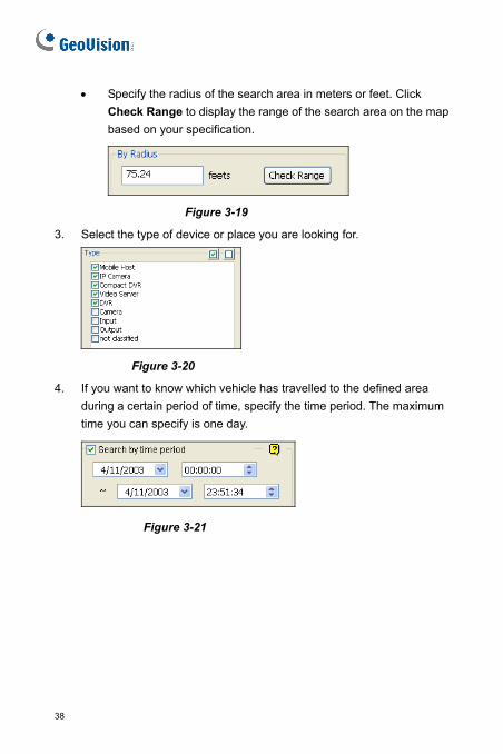
• Specify the radius of the search area in meters or feet. Click Check Range to display the range of the search area on the map based on your specification.
Figure 3-19
3. Select the type of device or place you are looking for.
Figure 3-20
4. If you want know which vehicle has travelled to the defined area during a certain period of time, specify the time period. The maximum time you can specify is one day.
to
Figure 3-21
38
Tracking Options for Mobile Hosts
3
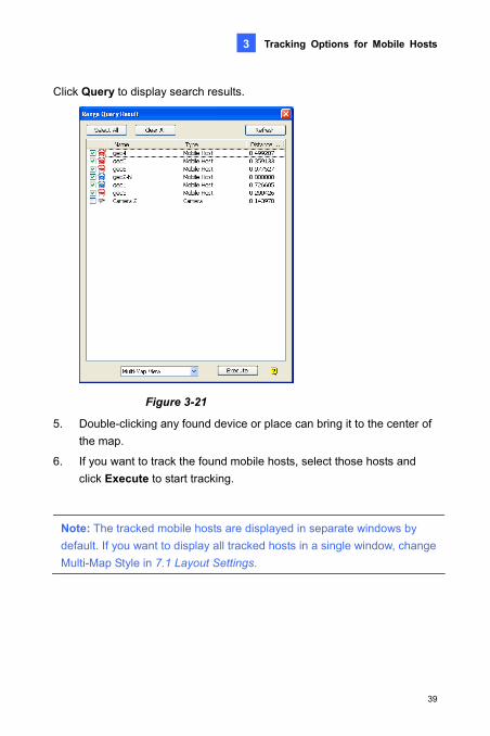
Click Query to display search results.
Figure 3-21
5. Double-clicking any found device or place can bring it to the center of the map.
6. If you want to track the found mobile hosts, select those hosts and click Execute to start tracking.
Note: The tracked mobile hosts are displayed in separate windows by default. If you want to display all tracked hosts in a single window, change Multi-Map Style in 7.1 Layout Settings.
39

Chapter 4 Monitoring Operations for Fixed Hosts
GPS.
Starting the Monitoring Services ut icons to their or the created E-Map
p, see 5.1 Creating an E-Map.
2. You can monitor the fixed host for the alert events of video motion and input trigger. Whenever movement occurs in the images or the input device is triggered, the alert message will be generated in the Event List and the related icons will start blinking on the Host List and map to alert you. See 4.3 Detecting Motion and Input-Triggered Events.
You can monitor the location of a fixed host without
4.1 1. Drag the Fixed Host, Camera, Input and Outp
appropriate positions on either the tracking mapfor live monitoring. For details on the E-Ma
40

Monitoring Options for Fixed Hosts
4
4.2 Monitoring Features On the map or the Fixed Host List, right-click the Fixed Host, Camera and
these monitoring features:
4.2.1 Fixed Host Icon
Output icons to have
Figure 4-1
Feature Description
Live View Live Video. Display live view. See 3.3 Viewing
Remote ViewLog Play back video recorded at the fixed host. See 4.4 Retrieving Recorded Video.
Send E-Mail Send an e-mail notificaiton. See Chapter 11 E-Mail Alerts.
Send SMS Message
Send a SMS notification. See Chapter 10 SMS Alerts.
Update Position to Host
Update the fixed host’s position to its Web interface. See 5.7 Applying Longitude and Latitude Positions on Fixed Hosts.
41

Event Monito ring. See 4.3 Detecting gger Events.
r Activate event monitoMotion and Input-Tri
Camera Monitor Setting
Disable the monitoring functions to certain Detecting Motion and
Input-Trigger Events. cameras. See 4.3
Information Display the host information.
Remove Marker Remove the host icon from the map.
4.2.2 Camera Icon
Figure 4-2
Feature Description
Live View Display live view. See 3.3 Viewing Live Video.
Instant Playback Play back video recorded at the fixed host. See
42

Monitoring Options for Fixed Hosts
4
4.4 Retrieving Recorded Video.
Remove Marke on from the map. r Remove the camera ic
Set Viewing Angle Set the viewing angle of the camera.
Direction Options Set the direction where you want the camera icon to point to, e.g. north, east and etc.
PTZ Change the camera icon to the PTZ icon.
4.2.3 Output Icon
Figure 4-3
Feature Description
Force Output Remotely trigger the output device installed at the fixed host. For this function to work, it is required to right-click the I/O host and select Event Monitor first.
4.3 Detecting Motion and Input-Triggered Events An alert message will be generated in the Monitor tab of Event List after video motion is detected and input device is triggered at the fixed host. Meanwhile, the related Camera and Input icons will start blinking to alert the user.
43

1. Right-click a fixed host to be monitored, anThe fixed host is
anThe fixed host is
d select Monito ent. e List does not
st button (No. 7, .
certain cameras, nitor Setting and clear the
3. In the Monitor List, click on the Monitor column. Select Motion to generate an alert message whenever movement occurs in the images, select Trigger to generate an alert message whenever the input device is triggered, or select Motion + Trigger to generate both types of alert messages.
d select Monitor Event. e List does not
st button (No. 7, .
certain cameras, nitor Setting and clear the
3. In the Monitor List, click on the Monitor column. Select Motion to generate an alert message whenever movement occurs in the images, select Trigger to generate an alert message whenever the input device is triggered, or select Motion + Trigger to generate both types of alert messages.
r Ev displayed in the Monitor List. If th
appear on the main screen, click the Monitor LiFigure 1-3) on the toolbar
displayed in the Monitor List. If thappear on the main screen, click the Monitor LiFigure 1-3) on the toolbar
2. If you want to disable the monitoring functions toright-click the fixed host, select Camera Moselections of those cameras.
2. If you want to disable the monitoring functions toright-click the fixed host, select Camera Moselections of those cameras.
Figure 4-4
Monitor List Event List Blinking Icon
44

Monitoring Options for Fixed Hosts
4
4.4 Retrieving Recorded Videos You can retrieve recorded videos from the fixed host for plaare two playb
yback. There ack options:
1. Instant Playback: Plays back the recorded video of a desired camera
2. Remote ViewLog: Plays back the recorded video of a desired fixed
playback function.
up to 5 minutes.
host.
Note: GV-IP Camera does not support the
4.4.1 Instant Playback
Before you can review the video recorded on the fixfunctions must be enabled to allow remote access:
ed host, the following
DVR: Enable Remote ViewLog Service on Control Center Server and activate recording.
Video Server, Compact DVR: Enable the Remote ViewLog function and activate the recording.
To retrieve recorded videos, right-click the Camera icon and select Instant Playback. If recorded videos exist, the playback window will be activated and playback will start.
45

Figure 4-5
following features: Right-click the Playback window to have the
Name Functions
Play Mode
Includes these options:
• Frame by Frame: Plays back video frame by frame.
• Real Time: Plays back video on real time. This mode saves waiting time for rendering, but drop frames to give the appearance of real-time playback.
• Audio: Turns on or off the video sound.
• Auto play next 5 minutes: Plays back video up to 5 minutes.
46

Monitoring Options for Fixed Hosts
4
Render low-quality and highly comp
• Defog: Enhances image
Includes these options:
ced video into video.
squares when
the coloring.
lock-like artifacts from ressed video.
visibility.
era shake.
a name and time: Overlays nto the video.
gand: Overlays POS or GV-Wiegand Capture data onto the video.
.
• Deinterlace: Converts the interlanon-interlaced
• Scaling: Smoothens mosaicack video, and applies the colorful enlarging a playb
mode to enhance
• Deblocking: Removes the b
• Stabilizer: Reduces cam
• Text overlay’s camercamera name and time o
• Text overlay’s POS/GV-Wie
• Full Screen: Switches to the full screen view
Tools
• Snapshot: Saves a video image.
• Save as AVI: Saves a video as avi format.
• Download: Downloads the video clip from the DVR or IP video device to the local computer.
Note: The Defog and Stabilizer only work when the functions have been applied on the recording from the DVR.
47

4.4.2 Remote ViewLog
Before you can review video recorded on the fixed host, the followfunctions must be enabled to allow remote access:
ing
Control Center Server.
Video Server, Compact DVR: Enable the Remote ViewLog function.
o install the Remote V-GIS computer.
g. The Remote amera and video event to
start playing. For detailed functions of the player, see Chapter 4 Playing Back Video Files, User’s Manual on Surveillance System Software DVD. If the player does not appear, click Configure on the menu bar, select System Configuration, click the Remote ViewLog tab, and verify the path of the installed Remote ViewLog program. See 7.4 Remote ViewLog Settings.
DVR: Enable Remote ViewLog Service on
To use the Remote ViewLog player, it is required tViewLog program from the software DVD to your G Right-click the fixed host and select Remote ViewLoViewLog player will appear. Select the desired c
48

Advanced Operations
5
Chapter 5 Advanced Operations
The E-Map allows you to import a floor plan in BMP, GIF and JPG formats, and use the icons of cameras and I/O devices to edit an electronic map according to your requirements. When the cameras and I/O devices are triggered at the host, the related icons will blink to warm you.
5.1 Creating an E-Map
Figure 5-1
1. On the host list, right-click New Map and select Add Map. A new Map folder is created.
2. Name the map folder, and click it to open.
3. Right-click the created map folder and select Load Map to import a graphic file.
4. Drag and drop the icons of cameras and I/O devices from the fixed host onto the map.
49

5. You can set the direction where you want the camera to point to, and a icon by right-clicking a
the host list to the location on the tracking map.
sed on either the tracking
change the camera icon into the PTZ camercamera icon.
6. You can also drag the created E-Map icon from correct
Note: The icons of cameras and I/O devices are umap or the E-Map.
5.1.1 Configuring E-Map Icon Settings
You can set options for the E-Map icon. Click the Map Setting button (No. 11, Figure 1-3) on the toolbar and click the E-Map Settings tab. This dialog box appears.
Figure 5-2
Visible Level in Map: Set the minimal zoom level of the E-Map icon on the tracking map. For example, if you set it to 14, you can only see the E-Map icon on the tracking map when zooming in to the level 14 or above. Setting the level to 0 makes the E-Map icon always visible regardless of zoom level.
Icon Size: Set large or small icons on the E-Map.
50

Advanced Operations
5
5.2 Adding a Place You can add a place marker of business or point of interest to the map.
1. On the host list, right-click Expended Markers and select Add Marker. This dialog box appears.
Figure 5-3
2. Name the place marker and select the icon.
3. Optionally, you can select Type if available and enter the details in the Note field to describe the place.
4. If you want to add a photo to describe the place, click Insert Syntax and select Insert Image. This dialog box appears. Click Search to locate the image path and name the image.
51

Figure 5-4
lace, click Insert Syntax t Hyper Link. The dialog box similar to Figure 5-35 appears.
Name and enter a web address.
ings, drag the created marker to the correct location on
see the information you added to
You can save a view of interest by creating a view marker. Every time when you click on the view marker, the map will return to the saved view.
1. Adjust the map to the desired view and zoom level.
2. On the host list, right-click Expended Markers and select Add Map View Region.
3. Name the view, select one icon, and click OK.
4. If you want to change the saved view, adjust the map to the desired view and zoom level, right-click the view marker and select Update Region.
5. If you want to add a web link to describe the pand selec
6. After above settthe map.
When you click the marker, you shoulddescribe the location.
5.3 Saving a View
52

Advanced Operations
5
is feature may not be
the starting point.
set the stop where you want to go before reaching to the final destination. You can configure multiple stops.
3. Right-click on the map, and select Destination to set the destination. A possible route and step-by-step directions are displayed.
5.4 Getting Driving DirectionsYou can get the step-by-step driving directions. Thavailable to your location depended on Maps API.
1. Right-click on the map, and select From to set
2. Right-click on the map, and select To to
Figure 5-5
The window ides the
estimated distance and
step-by-step directions.
The blue line displays your
possible route.
prov
53

4. You can send the driving directions to your e-mphone. Right-click the driving directions wi
ail account or mobile ndow and select Send
E-Mail or Send SMS. For this feature to work, you need to configure the mailbox or SMS server first. See Chapter 10 SMS Alerts or Chapter 11 E-Mail Alerts.
54

Advanced Operations
5
5.5 Self-Defining Event Colors The text and background colors for each event on tcan be self-defined for convenient checkup.
he Event List (Figure 1-4)
1. On the main screen, click Configure from the menu bar and select Event List Setting. This dialog box appears.
Figure 5-6
2. Select the desired type of event. It is shown in the drop-down list at the bottom of the dialog box.
3. Select Text Color or Background Color, and click on the drop-down list to edit the color.
4. Click OK to save the new color settings. All the events of the selected type in the Event List will change color based on the settings immediately.
55
56
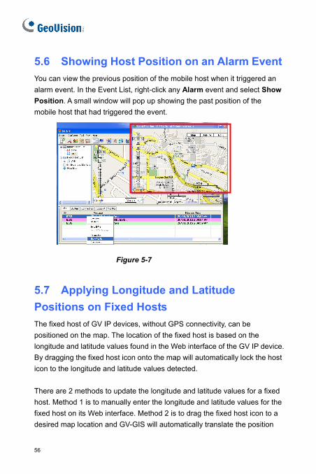
n Alarm Event ost when it triggered an
alarm event. In the Event List, right-click any Alarm event and select Show Position. A small window will pop up showing the past position of the mobile host that had triggered the event.
5.6 Showing Host Position on aYou can view the previous position of the mobile h
Figure 5-7
itude
The fixed host of GV IP devices, without GPS connectivity, can be positioned on the map. The location of the fixed host is based on the longitude and latitude values found in the Web interface of the GV IP device. By dragging the fixed host icon onto the map will automatically lock the host icon to the longitude and latitude values detected. There are 2 methods to update the longitude and latitude values for a fixed host. Method 1 is to manually enter the longitude and latitude values for the fixed host on its Web interface. Method 2 is to drag the fixed host icon to a desired map location and GV-GIS will automatically translate the position
5.7 Applying Longitude and LatPositions on Fixed Hosts

Advanced Operations
5
and fill it in the longitude and latitude fields in the Web interface of the fixed
tings on the Web interfaces t and select GPS Map Settings.
host.
Note: To access the longitude and latitude setof GV IP devices, select Managemen
Method 1 (When the longitude and latitude values are k
1. Access the account setting of the fixed host.
nown):
2. In the Host Information dialog box (Figure 2-3), select Apply the d host
titude values entered in the g the fixed host icon onto
correct position on the
Method 2 (When the longitude and latitude values are unknown):
1. Drag a fixed host icon onto the desired location on the map.
2. Right-click the fixed host and select Update Position to Host. The current map location for the fixed host is now updated to the longitude and latitude fields in the GV IP device’s Web interface.
3. When the longitude and latitude values for the fixed host is found and set with Method 2, GV-GIS operators can follow Method 1 steps to always lock the fixed host on the same position in the future.
Device’s GPS positions and click OK. The position of the fixeis updated based on the longitude and laGV IP device’s Web interface. When you drathe map, the icon will automatically move to its map.
57

5.8 Monitoring GV-I/O Boxes You can remotely monitor the I/O status and force any output device to be
rts GV-I/O Box 8/16
To add the I/O Box, follow the steps of Creating a earlier in this
the added I/O Box will be displayed on the Fixed Host List (No. 1, Figure
To monitor the I/O status, right-click the I/O host and select Event Monitor. The input and output triggers will be detected by GV-GIS. To remotely force any output, right-click one output icon and select Force Output.
triggered when needed. The application only suppoPorts with Ethernet Module.
Fixed Host chapter and select I/O Box to be Host Type. When the setup is completed,
1-2).
58

Event Log Browser
6
Chapter 6 Event Log BroThe GV-GIS records the events in five types of logs: Connection, Account and Monitor. With the e
wser Alarm, System,
vent logs in the Event Log ystem activities,
d events. On the toolbar, click the Event Log Browser button (No. 8, Figure 1-3) to start. Tip: Right-clicking an Alarm event, you can access the functions of Remote Playback, Instant Playback and Show Position.
Browser, you can obtain information about tracking alarms, shost connectivity, account changes and monitore
6-1
The buttons on the Event Log Browser:
Figure
No. Name Description
1 Open Open an event log. See Opening the Event Log later.
2 Reload Refresh the event log manually
3 Filter Define the search criteria. See Filtering the Event Log later.
4 Refresh the Filter Result Refresh the filter results.
59

5 Backup vent list. See Backing
later. Export the current eUp the Event Log
6 Page Setup header and footer for the printout
the event list. See Printing the Event Create aofLog later.
7 Print the current event list. Print
8 Exit Exit the browser.
9 Log Tab Click the log tabs of Alarm, System, Connection, Account and Monitor to get the related log events.
60
Event Log Browser
6
6.1 Opening the Event Log
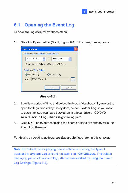
1. Click the Open button (No. 1, Figure 6-1). This dialog box appears.
To open the log data, follow these steps:
Figure 6-2
2. Specify a period of time and select the type of database. If you want to t System Log; if you want
l drive or CD/DVD, p Log. Then assign the log path.
3. Click OK. The events matching the search criteria are displayed in the Event Log Browser.
For details on backing up logs, see Backup Settings later in this chapter.
Note: By default, the displaying period of time is one day, the type of database is System Log and the log path is at: \GV-GIS\Log. The default displaying period of time and log path can be modified by using the Event Log Settings (Figure 7-3).
open the logs created by the system, selecto open the logs you have backed up in a locaselect Backu
61

6.2 Filtering the Event Log
1. Click the Filter button (No. 3, Figure 6-1). This dialog box appears.
You can filter log events on the defined criteria.
Figure 6-3
2. Specify the filter options that you want:
Read: Search for the events you have opened on the Event List reen.
rch for the events from a specific host or related to system activities.
Message: Search for the events by keywords. Message Time: Search for the events by the arriving time or date
to the GV-GIS. Start Time: Search by the starting time of the events occurred at
the host.
3. If you want to save your filter settings to another location, click Export. If you want to apply the pre-defined filter settings, click Import.
4. Click OK. The events matching the filter settings are displayed in the Event Log Browser.
that is at the bottom of the GV-GIS main sc Flag: Search for the flagged events. ID: Sea
62

Event Log Browser
6
6.3 Backing up the Event Log m to CD and DVD.
1. Click the Backup button (No.5, Figure 6-1). This dialog box appears.
You can back up logs to a local drive, or export the
Figure 6-4
th, click the […] button and assign a location wehere you want to save the files.
3. To export logs to CD and DVD, select Temp folder, click the […] button and assign a location for temporary storage of backup data.
4. For backup contents, you can select Backup GPS data files to back up GPS data and event logs; select Include GV-GIS Log Browser to include the Event Log Browser program with the backup data.
5. Click OK.
6. If you select Temp folder, this dialog box appears for further setup.
2. To back up logs to a local drive, select Backup Pa
63

Figure 6-5
Using CD/DVD: Click to back up files to the CD or DVD using the third-party software. Click the […] button to assign the desired burning software (.exe file).
CD Using OS-Burning: This option is only available when you use Windows XP, Server 2003 or Vista. It burns files to the CD or DVD using the inbuilt software of the operating system.
64

Event Log Browser
6
6.4 Printing the Event Log You can print out the filtered log events, and define the footer for the printout.
and header
e log events, click the desired log tab (No. 9, Figure 6-1) to display its log events.
2. Click the Page Setup Button (No. 6, Figure 6-1). This dialog box appears.
1. To print th
Figure 6-6
3. Select the options and type the information you want to for the header and footer and click OK.
4. Click the Print button (No. 7, Figure 6-1) to start printing.
65

Chapter 7 System Configurations To configure the GV-GIS system, click the System Configuration button
e toolbar.
7.1 Layout Settings
(No. 2, Figure 1-3) on th
Figure 7-1
Multi-Map Style: Select Multiple Window Mode to display tracked hosts in different windows; select Single Window Mode to display all tracked hosts in the same window. See 3.5 Tracking Multiple Hosts.
Measurement system: Select imperial or metric measurements.
Show Marker in separate maps: When the option is selected, the created Markers will also be shown in multiple tracking views (Figure 3-6).
Maximum number of Live View: Specify the maximum number of the Live View window displayed on the screen between 1 and 16. See 3.3 Viewing Live Video.
66

System Configurations
7
7.2 Network Settings
Figure 7-2
Port: The default communication ports are 3356, 80, 4512, and 943. If there is a router or firewall installed with the GV-GIS server, ensure these ports are open.
Start Service when GV-GIS starts: Automatically starts the service when the GV-GIS is started.
Start GIS Web Service when GV-GIS starts: Automatically starts the GIS Web service when GV-GIS is started.
Log in SMS Server when service starts: Automatically starts the SMS Server when GV-GIS services are started.
67

7.3 Event Log Settings
Figure 7-3
[Event List]
which data logs will be e 1-2) and the Event Log
wser (Figure 6-1) are opened. The number is between 1 and 7
ents in the List: Specify the maximum number of events displayed in the Event List. The number is between 500 and 500000.
[Event Log]
Keep Days: Select this option and specify the number of days to keep logs. Cleaning this option can keep logs for an unlimited period of time unless the disk space is full or the Recycle function is activated.
Recycle Log: Selecting this option will cause the oldest files to be deleted when the storage space is lower than 500 MB.
Log Path: Indicate the saved location of logs.
Import Day(s): Specify the number of days forloaded when the Event List (No. 8, FigurBrodays.
The maximum number of ev
68

System Configurations
7
7.4 Remote ViewLog Settings
Figure 7-4
[Panel Resolution] Select the panel resolution of the Remote ViewLog player.
[Position] Set the position of the Remote ViewLog player on screen. The position settings support negative coordinates and correspond to the XY coordinates in Windows Display Properties.
[Path] Specify the saved location of the Remote ViewLog program.
69
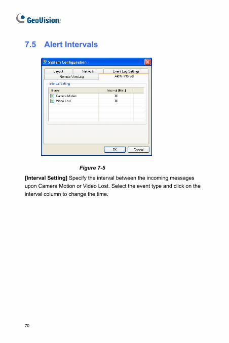
7.5 Alert Intervals
Figure 7-5
[Interval Setting] Specify the interval between the incoming messages upon Camera Motion or Video Lost. Select the event type and click on the interval column to change the time.
70

Notification Settings
8
Chapter 8 Notification SeWhen alert conditions occur, GV-GIS can automat
ttings ically activate the
assigned computer and output alarm to warn GV-GIS operators while a t out to warn related
persons. To access the function, click the Notification button (No. 4, Figure 1-3) on the toolbar.
pre-defined SMS and e-mail message are being sen
Figure 8-1
[List box] Select an alert condition in the left list box to be configu
[Alert Approach]
red.
Invoke Alarm: Select a computer alarm from the drop-drown list. Or, select User Define from the list to import one desired .wav sound. Click the Arrow button beside to test the assigned alarm.
Output Module: Select an installed output model and pin number to warn the operator.
Send E-Mail Alerts: Enable this option to send e-mails to warn related persons. Click the Edit button to edit a message. For Mailbox settings, see Chapter 11 E-Mail Alerts.
Send SMS Alerts: Enable this option to send SMS messages to warn related persons. Click the Edit button to edit a message. For SMS Server settings, see Chapter 10 SMS Alerts.
71

[Text Format of SMS] ASCII for English text, limited to 160 characters. code for other languages, limited to 70 characters.
igure the Mailbox and he e-mail address and
mobile number to the individual host’s account (see 2.2 Creating Host Accouts).
2. For output alarms, a GV-I/O Box should have been added to GV-GIS. See Chapter 9 Output Alerts.
Uni
Note:
1. For SMS and e-mail alerts, it is required to confSMS Server first. It is also required to enter t
72

Notification Settings
9
you can activate the output devices installed at host. Currently the application only
To install output devices on the GV-GIS, follow the steps below.
1. Click Configure from the menu bar of the main screen and select I/O Device Setting. This dialog box appears.
2. Select the I/O module from the Device drop-down list.
3. Select the COM port that the I/O module is connected to.
4. For the user of the GV-I/O and GV-Relay module, click the Format Address button to assign an address to the device. In the Format Address dialog box, start your first device with New Address set to 1 and click the Write button to write the address into the device.
5. For the user of the GV-I/O Box 4, 8 or 16 ports, the device address should be set on the device itself first. Select the correct address number from the Address drop-down list.
Chapter 9 Output Alerts When alert condition occurs, the GV-GIS site and at the remotesupports GV-I/O modules.
9.1 Adding Output Devices
Figure 9-1
73

6. Click the Add button. You should see the devicwindow.
e listed in the display
e devices, and remember to assign a for each device.
[Force Output] Click this button to force the output to be triggered.
[Signal Type] Select output signal to be normally closed (NC) or normal utput trigger will keep going on until a
t is triggered for the
-GIS ly force any output to be triggered when alert conditions
occur, see Chapter 8 Notification Settings. To manually force any output to be triggered, click the Local I/O Device Control button (No. 5, Figure 1-3), select a desired module and then click Finger button to trigger it.
9.2 Forcing Outputs of a Host See 4.2.3 Output Icon.
7. Repeat above steps to add mordifferent address
Other options on the I/O Device dialog box:
[Name] Name the output device.
open (NO). For Toggle status, the onew trigger happens. For Pulse status, the outpuamount of time specified in the Sec field (seconds).
9.1 Forcing Outputs of GVTo automatical
74

SMS Alerts
10
Chapter 10 SMS Alerts You can send SMS messages to warn related persons when alert
Server Before sending SMS messages, you need to define SMS Server correctly.
1. On the main screen, click Configure from the menu bar and select SMS Setting. This dialog box appears.
conditions occur.
10.1 Setting SMS
Figure 10-1
2. Type the IP address, communication port, Login ID and Password of the SMS Server.
3. If the SMS Server is installed on the same computer with the GV-GIS, select Local. If not, select Remote.
4. To configure up to three mobile numbers of operators to get notified when the GV-GIS loses connection to SMS Server, click the Mobile Setup tab. This dialog box appears.
75

Figure 10-2
5. Select one mobile icon, select Add to SMS List, and type country code and mobile number.
6. To set time intervals between each SMS message when alert occurs, click the SMS Option tab. This dialog box appears.
Figure 10-3
5. In the SMS Alert Setup field, set the interval between 0 and 1440 minutes.
For details on building a SMS Server, see Chapter 10, User’s Manual on the Surveillance System Software DVD.
76

SMS Alerts
10
10.2 Connecting to SMS Server On the main screen, select Configure from the menu bar and select
ver for connection to SMS Server.
GV-GIS is established, there are
1. To automatically send SMS messages when alert conditions occur, see Chapter 8 Notification Settings.
2. To manually send SMS messages to warn any person anytime, right-click one host on the Host List or on the map, select Send SMS Message, and enter the desired mobile number and contents for alerts.
Connect to SMS Ser
10.3 Sending SMS Once the connection of SMS Server and several ways to send SMS messages.
77

10.4 Inserting ID and Camera Name to Alert
lly inserted to your SMS .
1. Click the Notification button (No. 4, Figure 1-3) on the toolbar. The Alarm Settings dialog box appears.
2. Select an alert condition in the left list box, select Send SMS Alerts. This dialog box appears.
Messages The host’s ID and camera name can be automaticamessage when it is sent out
Figure 10-4
and click Macros. This dialog box appears. 3. Type the message text
Figure 10-5
78

SMS Alerts
10
4. Place the pointer in the text where you want to insert the ID, Name, Message Time or GPS Position, select the corresponding symbol from
The symbol will be replaced with the real information when the message is displayed to a reader.
the right column, and click Insert.
79
Chapter 11 E-Mail Alerts You can send e-mails to related persons when alert conditions occur.
11.1 Setting Mailbox ail to an e-mail account, you need to define
11.1.1 Setting up the mailbox
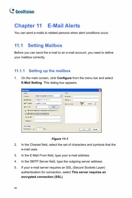
1. On the main screen, click Configure from the menu bar and select E-Mail Setting. This dialog box appears.
Before you can send the e-myour mailbox correctly.
Figure 11-1
2. In the Charset field, select the set of characters and symbols that the e-mail uses.
3. In the E-Mail From field, type your e-mail address.
4. In the SMTP Server field, type the outgoing server address.
5. If your e-mail server requires an SSL (Secure Sockets Layer) authentication for connection, select This server requires an encrypted connection (SSL).
80

E-mail Alerts
11
6. If your e-mail service provider requires authentication for sending tication, and type the
want to set time intervals between each e-mail message when alert occurs, in the Alert Setup field, set the interval between 0 and
Test E-Mail
Test section and send a
ddress in the E-Mail To field.
2. Enter a subject for the e-mail.
ssage in the Mail Content field.
11.2 Sending E-Mail There are several ways to send e-mails.
1. To automatically send e-mails when alert conditions occur, see Chapter 8 Notification Settings.
2. To manually send e-mails to warn any person anytime, right-click any host on the Host List or on the map, select Send E-Mail, and enter the desired mail address and contents for alerts.
e-mails, select SMTP Server requires authenaccount ID and password of your SMTP.
7. If you
1440 minutes.
8. Click OK.
11.1.2 Sending a
After setting up your mailbox, message to your own e-mail account for testing.
you can use the
1. Enter your own e-mail a
3. Type the desired me
4. Click the Test Mail button.
81

Chapter 12 Failover SuppoYou can configure up to two backup servers in case of the prima
rt ry GV-GIS
server takes over the r, providing uninterrupted GIS services.
1. It is required to pre-configure the backup server with the same account settings as the primary station first.
2. On the main screen, select System from the menu bar, and select Automatic Failover Support. This dialog box appears.
server failure. Whenever the primary fails, the backupconnection from the primary serve
12-1
s dialog box appears.
Figure
3. Click the Add button to add one server. Thi
Figure 12-2
4. Type the IP Address of the backup server. Keep the default port setting or modify it if necessary.
82

Failover Support
12
5. Click OK. When the primary GV-GIS server fails, all connections from server.
Note: Once the primary station is ready to resume the services, it is required to close the backup station so the connection from subscribers can move back to the primary.
subscribers will be diverted to the backup
83

Chapter 13 Remote Viewing Using a Web Browser
a Web browser.
for remote viewing.
You can remotely access the GV-GIS through
Note: You need Internet Explorer 7.x or above
13.1 Creating Web Accounts
GV-GIS’s Web interface. There are two types of accounts: Supervisor and User. Supervisor accounts have all the privileges to all hosts, while User accounts have the specified privileges on the selected hosts.
1. On the toolbar, click the Web Account button (No. 5, Figure 1-3). This dialog box appears.
You can create web accounts with different privileges to access the
Figure 13-1
84

Remote Viewing Using a Web Browser 13
2. Select one type of account on the left list: Supervisor or User. Then ount under the
e account’s privileges
e user account.
f the selected hosts.
to the recordings of the sts.
Change Log Status: Allows marking events in the Event List with color flags or unmarking the events. The feature is useful not only when browsing in the Event List but also when searching the events.
Force Output: Allows forcing the output of the selected host to be triggered.
click the Add Account button to create an accSupervisor or User.
3. If you create a User account, you can limit thwith the following options:
Enable Account: Enable or disable th
Live View: Allows access to live view o
Remote Playback: Allows accessselected ho
Event Log: Allows access to the Event List and Event Log.
85

13.2 Accessing the Web InterfacYou can access the GV
e -GIS remotely through network. To access the
the Web Service (No. 3, Figure 1-3) on the
ternet Explorer browser.
2. Enter the IP address or the domain name of the GV-GIS in the Location/Area filed of your browser. The first-time user will be prompted to install Windows Silverlight. After the installation, this web page appears.
GV-GIS’s Web interface, ensureGV-GIS has been enabled.
1. Start the In
Figure 13-2
3. Enter the ID and password of a web account to log into the Web interface.
86

Remote Viewing Using a Web Browser 13
4. Click Login. This Web page appears.
Figure 13-3
87

13.3 Accessing Monitoring FeaOn the map or the host list, right-click the Host icon
tures to access the tracking,
live video and remote playback features. The Input and Output icons can trigger status of I/O devices in real time. You can also force
any Output device to be triggered.
13.3.1 Host Icon
provide you the
Figure 13-4 Mobile Host Icon
Figure 13-5 Fixed Host Icon
Feature Description
Track Marker Only available for Mobile Host Icon. Always keep the host icon staying at the center of the map when the vehicl moves. A yellow block similar to the following figure will be displayed on the map. Clicking the yellow block will stop the host tracking.
88

Remote Viewing Using a Web Browser 13
Live View Display live view. See 13.from a Web Browse
4 Viewing Live Video r.
Remote Playba recorded at the host. See 13.5 Retrieving Recorded Videos from a Web Browser.
ck Play back videos
Connect to the Web Interface
interface of the host. Access the Web
13.3.2 Input and Output Icons
Figure 13-6
Feature Description
Input When the input is triggered, the input icon will blink to warn users.
Output When the output is triggered, the output icon will blink to warn users. You can also remotely trigger the output by righ-clicking the ouput icon and selecting Force Output.
89

13.4 Viewing Live Video from a Web Browser
ing Live View window will appear.
If the remote video device is the GV-System (DVR), ensure to enable its WebCam Server to allow the remote access.
To view live video in the GV-GIS’s Web interface, right-click one Host icon and select Live View. The follow
Figure 13-7
Note: It is required to modify the GV-GIS Http port number or the WebCam Server’s Http port number if the two are run on the same computer. Follow the instructions in Appendix E.
The controls on the Live View window:
No. Name Description 1 Play Play live video.
2 Stop Stop playing video.
90

Remote Viewing Using a Web Browser 13
3 Microphonce area from the local
ne Talk to the surveillacomputer.
4 he camera. Speaker Listen to the audio around t5 Snapsho a snapshot of live video. t Take6 File Save Record live video to the local computer.
7 Full Screen . Right-click the image to
have these options: Snapshot, PAP, PIP, Zoon in and Zoom Out.
Switch to full screen view
8 Change Camera Select the desired camera for video display. 9 PTZ Control Start the PTZ control panel.
91

13.5 Retrieving Recorded Videos from a Web
retrieve recorded videos of any desired host from the GV-GIS’s rded on a remote video
t the remote video device to
iewLog Service on Control
CAM: Enable the
Remote Playback.
2. The Single Player program will be downloaded to your computer automatically. Set your browser to allow the once-only installation of Single Player program and ActiveX components onto your computer.
3. Once the installation is complete, the Connect to the Remote ViewLog Service dialog box will appear. Enter the login information of the host and click Enter. This playback window appears.
Browser You canWeb interface. Before you can review videos recodevice, the following function must be enabled aallow access:
GV-System (DVR): Enable Remote VCenter Service.
GV-Video Server, GV-Compact DVR, GV-IPRemote ViewLog function.
1. Right-click one Host icon and select
Figure 13-8
92

Remote Viewing Using a Web Browser 13
4. Select a desired video event from Video Evenbutton to review the vid
t List, and click Play eo.
5. Right-click the Playback window to have more features. For details, see 4.4 Retrieving Recorded Videos.
93

13.6 Accessing the Event Log from a Web
eb interface to obtain d events.
1. Click the Tool button in the upper right corner of the Web page, and select Event Log. This dialog box appears.
Browser You can access the Event Log from the GV-GIS’s Winformation of alarm and monitore
Figure 13-9
2. Click the Filter button.
3. Specify the filter criteria to search the desired events. For details, see 6.2 Filtering the Event Log.
94

Remote Viewing Using a Web Browser 13
13.7 Getting Driving Directions from a Web
m the GV-GIS’s Web location depended on
your IP
his web service; u cannot access this feature.
he map, and select From to set the starting point.
2. Right-click on the map, and select To to set the stop where you want to go before reaching to the final destination. You can configure multiple stops.
3. Right-click on the map, and select Destination to set the destination. A possible route and step-by-step directions are displayed in the left-side box on the map.
Browser You can get the step-by-step driving directions frointerface. This feature may not be available to yourMaps API.
If the MAP API you select is the Google MAP, ensure to register address with the Google Maps API before starting totherwise yo
1. Right-click on t
95

Appendix
A. Dongle Options se dongle options for GV-GIS applications:
• GIS + AVP
gle ngle can be upgraded to include
more functions or enhance the system. You need to collect the data from your dongle and send it back to GeoVision for an upgrade. The upgrade is a charged service. To upg your dongle, follow these steps:
he side of the al dongle or on the back of the Internal dongle. Later this serial
number will be used in naming the files for upgrading.
You have the
• GIS
• GIS + VSM
• GIS + VSM + AVP
• NVR + LPR + GIS
B. Upgrading the GV-GIS DonNo matter external or internal, the USB Do
rade
1. Each dongle has its own serial number. Find it on tExtern
10090031
External Dongle Internal Dongle
2. Insert the dongle to the computer if you use an External dongle.
3. In the GIS folder, double-click GVUsbKeyUpClient.exe. This dialog box appears.
96

Appendix
lect All. The formation field. Note
umber of “HW Serial” should be the same as that on
5 Save Key ID Data. If click Batch Save. te files. The file will be nd saved as *.out. For
42, the file is named
d this data file to GeoVision at [email protected]
4. To retrieve the data from the dongle, click Seinformation of the dongle is displayed in the inthe displayed nthe dongle.
. To save the data to your local computer, clickyou have more than one dongle to upgrade, Different dongle data will be saved as separanamed after the serial number on the dongle aexample, if a dongle serial number is 71164“NVR-7116442.out”.
6. Sen . The GeoVision will examine the data file and send an *.in file back to you. The file name also includes the serial number of that dongle. In this example, the data file you will receive is named “NVR-7116442.in”.
7. After you receive the updated file, insert the correct dongle matching the .in file you receive, and then run GVUsbKeyUpClient.exe.
8. Click Select All to read the dongle, click Upgrade and then open the updated file to upgrade the dongle. You can also select more than one dongle in the list and click Batch Upgrade to upgrade them at the same time. Make sure these dongles match the updated files you receive.
97

C. Installing the Internal USB DThe GV-Internal USB Dongle, serv
ongle ing as Hardware Watchdog, is designed
ashes, such as the operating .
Hardware Watchdog function is only available on the GV-Internal USB Dongle version 2.01 or above. To verify the version number, see the sticker on the side of the dongle as illustrated below. You can also find the serial number XXXXXXXX on the back of the dongle as illustrated below.
to restart the computer when the Windows crsystem freezes or the Blue Screen problem occurs The built-in
Besides the built-in Hardware Watchdog, the GV-Internal USB Dongle can serve as a key for various GeoVision hardware and software activations (see Software or Hardware Requirements section below) and also be included AVP functions. To include multiple functions into the GV-Internal USB Dongle, please contact your sales representatives.
98

Appendix
Software or Hardware Requirements The GV-Internal USB Dongle is required to work with any of the following
re. The Hardware Watchdog only functions when any
above
es (Center V2, Dispatch Server, Vital Sign Monitor
ontrol Center) V8.3.2 or above
ger V2.2 or above
3.1.2 or above
.1 or above
4008 Card
le
GV-Video Gateway
GV-Backup Center
Connections 1. Turn off the computer, and open the case.
2. Connect the GV-Internal USB Dongle to the internal USB headers on the motherboard.
software and hardwaof the GV software is started.
GV-NVR V8.3.2 or
GV-CMS Seri
(VSM), C
GV-ASMana
GV-LPR V
GV-GIS V2
GV-
AVP Dong
POS Text Sender
99

3. Remove the wire of the computer’s reset switchand connect it to th
from the motherboard, e GV-Internal USB Dongle. Use the supplied
Jumper Wire to connect the pins on the GV-Internal USB Dongle and the reset pins on the motherboard.
100

Appendix
Note:
1. For some motherboards, the internal USB headers are integrated with an extra connector, making it unfit for the GV-Internal USB Dongle to plug in. It is required to use a connector supplied with the motherboard to connect the GV-Internal USB Dongle to the motherboard.
The GV-Internal USB Dongle
+5
V
P1
-
P1
+
GN
D
+5
V
P1
-
P1
GN
+ D
The connector supplied with the motherboard
The USB headers with an extra USB connector
2. Ensure not to remove the GV-Internal USB Dongle when the computer power is on, or it would cause the computer to restart or the GV-Internal USB Dongle to be damaged .
4. Install the USB Dongle driver from the Software DVD.
101

5. To verify the driver is installed correctly, go to Device Manager and expand the DVR-Devices filed. You should see one entry for GV-Series USB Protector.
Note: Ensure to use USB driver V1.0.8.1 or above for the
GV-Internal USB Dongle to function. To verify the driver version is
compatible, right-click GV-Series USB Protector, select
Properties and click the Driver tab.
102

Appendix
D. Sho eys rtcut KShortcut Keys Description
F2 window for account settings. Open the Account
F3 alog box for account search. Open the Find di
F4 Go to the tracking map.
F5 Open or close the Event List.
F6 Open or close the Monitor List.
F7 Open the Range Query dialog box to search for places and devices.
F8 Open the E-Map Setting dialog box to set the minimal zoom level of the E-Map icon on the tracking map.
F9 Open the System Configure dialog box.
F10 Open the Log Browser.
103

E. Specifications Feature Amount Device
Mobile Host Up to 50(dependi gle in use)
GV-Video Server
GV-Compact DVR
0 hosts ng on the Don
Fixed Host Unlimited
GV-DVR/NVR GV-Video Server GV-Compact DVR GV-IP Cam GV-Speed Dome GV-Smart Box
-I/O Box 8/16 Ports (Ethernet Module) GV-LPR
GV-DSP LPR
3rd-party IP devices
GV
I/O Module 9 units -I/O
-I/O Box (4/8/16 Ports)
GV
GV
Live View 16 views Mobile Hosts + Fixed Hosts
Map View 16 views Mobile Hosts
Marker Unlimited
ViewLog 1 Remote ViewLog program required to be installed
Instant Playback 1
104

Appendix
F. Modifying Port Number for running GV-GIS ystem stem use the same
HTTP port number of 80 to connect to the Web, it is required to modify the if the two are run on the interface of the GV-GIS.
y the HTTP port number of GV-GIS:
1. Click Configure from the menu bar and select System Configure.
2. In the Network section, change the default Listen Port of 80 to a
different port number within the range of 1024 to 65535.
3. Click OK.
on the same computer with GV-SSince the GV-GIS and the WebCam Server of GV-Sy
port number of either GV-GIS or WebCam Server same computer. If not, you cannot access the Web
To modif
105