guidelines for road works, drainage and subdivision ... · doc id 33063 guidelines for road works,...
TRANSCRIPT
Doc ID 33063
GUIDELINES FOR ROAD WORKS, DRAINAGE AND SUBDIVISION DEVELOPMENT
Adopted 12 September 2002 Updated 22 July 2014
Attachment A
1
1. GENERAL REQUIREMENTS ............................................................ 3 2. DESIGN AND CONSTRUCTION CRITERIA .................................. 6
2.1. General ................................................................................... 6 2.2. Roads ...................................................................................... 6
2.2.1. General .............................................................................. 6 2.2.2. Urban Roads (other than Industrial) ................................... 7 2.2.3. Industrial Roads ................................................................. 7 2.2.4. Rural Residential Roads ..................................................... 7 2.2.5. Rural Roads ....................................................................... 8 2.2.6 Roman Data ....................................................................... 8
2.3 Design Standards – General .................................................... 9 2.4 Public Utility Conduits ............................................................ 10 2.5 Clearing and Stripping ........................................................... 10 2.6 Earthworks ............................................................................ 11 2.7 Subgrade and Foundation Preparation ................................. 11 2.8 Pavements ............................................................................. 12
2.8.1 Pavement Design ............................................................... 12 2.8.2 Base course Widths ............................................................ 12 2.8.3 Shoulders ........................................................................... 13 2.8.4 Compaction ........................................................................ 13 2.8.5 Materials ............................................................................. 13
2.9 Kerbing .................................................................................. 18 2.10 Stormwater Drainage ........................................................... 18
2.10.1 General ............................................................................. 18 2.10.2 Common Catchments ....................................................... 19 2.10.3 Recurrence Intervals & Run-off Coefficients ..................... 19 2.10.4 Provision for Flooding ....................................................... 19 2.10.5 Pipe Types ........................................................................ 20 2.10.6 Underground Pipe Systems .............................................. 20 2.10.7 Open Drains ..................................................................... 21 2.10.8 Sub-Soil Drains ................................................................. 21 2.10.9 Drainage Easements ........................................................ 22
2.11 Miscellaneous Facilities ...................................................... 22 2.11.1 Footpaths .......................................................................... 22 2.11.9 Fencing for subdivisions outside of townsites ................... 31 2.11.10 Provision for School Bus Facilities .................................. 32
3. SUBMISSION REQUIREMENTS ..................................................... 33 3.1 General .................................................................................. 33 3.2 Drawings ................................................................................ 33 3.3 Drainage Calculations ............................................................ 33 3.4 Pavement Calculation ............................................................ 33 3.5 Required Drawings ................................................................ 34 3.6 As Constructed Drawing Details ............................................ 35
4. CONTROL & SUPERVISION OF CONSTRUCTION ................... 36 4.1 General .................................................................................. 36 4.2 Responsibility for Quality of Construction .............................. 36 4.3 Schedule of Inspections ......................................................... 36 4.4 Testing & As Constructed Surveys ........................................ 37
Attachment A

2
4.5 Practical Completion .............................................................. 38 5 MAINTENANCE AND RELEASE .................................................. 39
5.1 Survey Release ...................................................................... 39 5.2 Maintenance .......................................................................... 39
Attachment A
3
1. GENERAL REQUIREMENTS
1.1. Where proposals for the subdivision of land in a district include the provision of streets for use by the public, and the proposals have been approved, the owner of the land shall not dispose of it, or part of it or an estate or interest in it, until he has caused those streets to be constructed and drained to the satisfaction of the Council (Section 295 (4) (a) Local Government (Miscellaneous Provisions) Act 1960).
1.2. Any road and/or drains required to be constructed under the preceding
section of the Local Government Act, shall be constructed to Council’s requirements.
1.3. The term “Subdivider” shall mean the owner of the land being subdivided.
The term “Consulting Engineer” or “Consultant” shall mean the Engineer appointed by the Subdivider to design, document and superintend construction of the works.
1.4. Technical provisions included in these requirements are intended to provide
a guide to the standard of work, materials and design required before roads and drains will be certified to the Western Australian Planning Commission as having been made to the satisfaction of the Council. They are not necessarily complete and are not intended to be used as a specification or contract for construction. They may be subject to alteration with the approval of the Works Manager
1.5. The Local Government (Miscellaneous Provisions) Act 1960, Section 295
(6) reads as follows:
“(a) Where a person who is subdividing land is by the provisions of this Part required to construct and drain streets shown in the plan of subdivision he may-
(i) carry out or cause to be carried out the construction and
drainage at his own cost and expense or; (ii) arrange for the Council to carry out the work on his behalf and
at his cost and expense (b) Where the person does not make the arrangements with Council, he
shall pay to it, on demand, an amount to cover the reasonable costs of the Council in supervising the construction and drainage which amount shall be reckoned as follows:
(i) where the person has not engaged a Consulting Engineer and
Clerk of Works to design and supervise the construction and drainage the amount shall be three (3) percent of the cost of the construction and drainage as estimated by the Council;
Attachment A
4
(ii) where the person has employed a Consulting Engineer and Clerk of Works to design and supervise the construction and drainage, the amount shall be one and one-half (1 ½ ) percent of the cost of the construction and drainage as estimated by Council.
(c) The Council may require the person to employ a Consulting Engineer
and Clerk of Works to design and supervise the construction and drainage and that person shall, when required to do so by Council, carry out the requirement.”
1.6. The design, preparation of drawings and specifications, and supervision of
construction of subdivision works covered by these requirements shall be undertaken by a Consulting Engineer who is a member (or is eligible by way of engineering qualifications and experience to be a member) of the Association of Consulting Engineers Australia.
1.7. The supervision fee referred to in Section 295(6)(b) of the Local
Government (Miscellaneous Provisions) Act 1960 shall be paid to Council before construction commences.
The amount of the payment shall be based on the estimated cost of all of the works at the time. Upon certification of practical completion of the works, the consultant shall provide the actual construction cost of the works and the amount of the fee shall be adjusted accordingly, if necessary.
1.8. Drawings and specifications for the construction of roads and drains shall
be prepared in accordance with Section 3 of these requirements and must be approved by Council’s Works Manager before any work will be allowed to commence.
1.9. All construction work shall be carried out in accordance with the approved
drawings and specifications and shall be subject to inspection at various stages of the works by Council’s Works Manager. Final approval of the works shall only be given when the whole of the works have been constructed to the true meaning and intent of the approved drawings and specifications and to the satisfaction of Council’s Works Manager.
1.10. Council’s Works Manager will direct all notices, requests, instructions and
approvals to the Consulting Engineer, except in urgent circumstances when they may be given directly to other parties involved in the subdivision.
1.11. After clearance of the diagrams by the Western Australian Planning
Commission and the Office of Titles, any land delineated and shown as a new road on such diagrams shall then be under the control of Council subject to the maintenance requirements referred to in Section 5.
1.12. Council is conscious of the need to preserve natural vegetation wherever
possible in rural subdivisions. To this end, Council may impose special conditions on particular subdivisions to minimise the environmental impact
Attachment A

5
of road and drainage constructions, particularly in relation to preservation of established trees within road reserves and minimising soil erosion. Subdividers should be conscious of these aims and should take them into consideration in the various stages of planning for a subdivision.
Attachment A
6
2. DESIGN AND CONSTRUCTION CRITERIA
2.1. General
Criteria provided here are minimum criteria only and are necessarily broad based to cover general subdivision situations. In particular situations amendments may be required and Council may impose special conditions not covered by the criteria.
2.2. Roads
2.2.1. General
Roads should generally be designed in accordance with relevant Austroads (NAASRA) and ARRB guidelines and publications. However, consideration must be given to the final aesthetic and functional aspects of the area, particularly in rural areas. Aspects to be considered include minimising the environmental impact (particularly regarding existing trees and vegetation), fitting road grades as close to existing contours as practicable and provision of lot access. Local roads shall have a minimum road reserve width of 20 metres. However, Council reserves the right to make a wider road reserve should the site or engineering requirements dictate. The designation of which road types shall apply to a particular subdivision (i.e. townsite residential, rural, rural residential or industrial) shall be at the discretion of the Council and the Subdivider shall comply with the requirements for those designations. Council has identified minimum road standards, given known and/or estimated Annual Average Daily Traffic (AADT) counts based on those referenced in the State Roads Development Strategy (Roads 2020).
Type 1 Unformed road, minimum construction Type 2 Formed road constructed from surrounding local material Type 3 Formed road paved with imported gravel material Type 4 Sealed road (6m seal width) Type 5 Sealed road (7m seal width) Type 6 Sealed road (8-9m seal width) Type 7 Sealed road with overtaking lanes Type 8 Dual carriageway – divided rural road
Attachment A
7
2.2.2. Urban Roads (other than Industrial)
7.0 m wide, concrete kerbed with 25mm asphalt surface. The maximum longitudinal grade of a road shall be 8% unless otherwise approved. The minimum longitudinal grade shall be 0.5%. A vertical curve shall be provided when the grade change is 1% or greater. Verges shall have sufficient width for the provision of public utility services, and shall be a minimum of 3.5m. Verges shall normally be graded at +2% from the top of the kerb to the property boundary. In areas of steep crossfall or where earthworks should desirably be reduced to minimise environmental impact, the verge grading may be increased as agreed with Council’s Works Manager. Cul-de-sacs shall have a minimum head radius of 9m with 15m radius tapers. Kerb type shall be mountable to residential frontages and semi-barrier elsewhere. Refer to Section 2.8 for pavement design and make-up.
2.2.3. Industrial Roads
In light industrial areas, roads shall be kerbed and sealed to a minimum width of 7.4 m. All other design criteria shall be in accordance with the requirements for Urban Roads with the following exceptions: - Verge width to be a minimum 4.5m; - Cul-de-sacs shall be avoided wherever possible; - Kerbs shall be semi-mountable. In heavy industrial areas, road construction requirements will be subject to specific engineering design.
2.2.4. Rural Residential Roads
The minimum standard for rural residential subdivision will be a Type 4 road as referenced in 2.2.1.
Road reserves will be 30 metres width, however may be varied at the discretion of Council. Main distributor roads (in and out of the subdivision) and minor service roads to be 6.5 meters in width however, this maybe negotiable dependent on the circumstances.
Attachment A
8
Intersections
a. All intersections shall be provided with concrete kerbing to an extent
determined by Council’s Works Manager b. All intersections shall be provided with a 25mm asphalt surface to the
full extent of the concrete kerbing. c. All intersections to be 7 metres sealed in width between kerbing at
intersection.
The maximum longitudinal grade of a road shall be 8% unless otherwise approved. The minimum longitudinal grade shall be 0.5%. A vertical curve shall be provided when the grade change is 1% or greater. Verges shall have sufficient width for the provision of public utility services, and shall be a minimum of 3.5m. In areas of steep crossfall or where earthworks should desirably be reduced to minimise environmental impact, the verge grading may be increased as agreed with Council’s Works Manager. Cul-de-sacs shall have a minimum head radius of 9m with 15m radius tapers.
2.2.5. Rural Roads
Rural roads shall comply with the standards prescribed in the Roads 2020 Strategy (refer 2.2.1), and will be dependent on estimated AADT counts.
Where existing rural roads are considered by Council to warrant sealing, the width of such sealing shall be a minimum of 7 metres with a road formation of 10 metres.
2.2.6 Roman Data
The developer shall be responsible for providing inventory data for inclusion in Councils ROMAN Pavement Management System. Each road shall have a completed Data Collection Sheet, as appended. Intersection locations may be scaled from As Constructed drawings as well as point item locations i.e. road signage, traffic control devices as indicated on the data collection sheet. All conditions shall be considered to be as new, if this is not the case, notes detailing the change in conditions shall be included with the data collection sheet.
Attachment A
9
2.3 Design Standards – General
Unless otherwise referenced, road designs shall comply with the following criteria: Geometric design shall be according to ‘Rural Road Design’, Austroads 1989. The minimum design speed for access roads shall be 60km/hr, collector roads 70 km/hr and arterial roads 90km/hr. The maximum longitudinal grade of a road shall be 12.5% unless otherwise approved. The minimum longitudinal grade shall be 0.5% unless table drains are graded independently of the road to provide satisfactory drainage, where necessary. A vertical curve shall be provided when the grade change is 1% or greater One-way crossfall to a maximum of 3% may be approved for access roads when excessive crossfall exists in the natural surface. Roads shall normally have two-way crossfalls of 3% except where geometric design requirements dictate that superelevation is required. Table drains shall be provided for all roads for a minimum width of 1.2m, flat bottomed, with side slopes of a minimum 1:3 grade (33%). Cut batters shall generally be no steeper than 1 in 3 (33%) except in hilly terrain, or where depth of cut is considerable, or where ground conditions are such that it is not practicable to comply with this requirement without excessive cost or environmental disturbance. Then, subject to the approval of Council’s Works Manager, cut batters may be increased to a maximum of 1 in 1 (100%). Fill batters shall generally be no steeper than 1 in 4 (25%) except in hilly terrain or where fill heights are considerable, in which case a maximum slope of 1 in 2 (50%) may be used subject to the approval of the Works Manager.
- Verges shall have sufficient width to install public utility services. In
particular sufficient width must be provided to install overhead power lines with poles located at least 2.5 m from the invert of the table drain.
- Roads shall be designed to enable access to lots at an absolute
maximum grade of 16%.
- Cul-de-sacs heads shall have a minimum head radius of 9m to edge of seal, with 15m radius tapers.
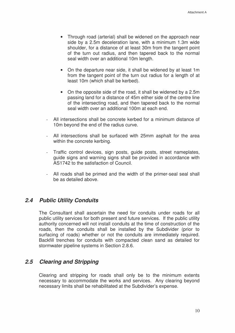
- Intersections of arterial roads shall be widened as follows:
• Terminating road (collector or access) shall be widened to at
least 7.4m seal width for a straight length of 10m from the tangent point of the turn-out radius, and then tapering to the normal seal width over an additional 10m length.
Attachment A
10
• Through road (arterial) shall be widened on the approach near
side by a 2.5m deceleration lane, with a minimum 1.3m wide shoulder, for a distance of at least 30m from the tangent point of the turn out radius, and then tapered back to the normal seal width over an additional 10m length.
• On the departure near side, it shall be widened by at least 1m
from the tangent point of the turn out radius for a length of at least 10m (which shall be kerbed).
• On the opposite side of the road, it shall be widened by a 2.5m
passing land for a distance of 45m either side of the centre line of the intersecting road, and then tapered back to the normal seal width over an additional 100m at each end.
- All intersections shall be concrete kerbed for a minimum distance of
10m beyond the end of the radius curve.
- All intersections shall be surfaced with 25mm asphalt for the area within the concrete kerbing.
- Traffic control devices, sign posts, guide posts, street nameplates,
guide signs and warning signs shall be provided in accordance with AS1742 to the satisfaction of Council.
- All roads shall be primed and the width of the primer-seal seal shall
be as detailed above.
2.4 Public Utility Conduits
The Consultant shall ascertain the need for conduits under roads for all public utility services for both present and future services. If the public utility authority concerned will not install conduits at the time of construction of the roads, then the conduits shall be installed by the Subdivider (prior to surfacing of roads) whether or not the conduits are immediately required. Backfill trenches for conduits with compacted clean sand as detailed for stormwater pipeline systems in Section 2.8.6.
2.5 Clearing and Stripping
Clearing and stripping for roads shall only be to the minimum extents necessary to accommodate the works and services. Any clearing beyond necessary limits shall be rehabilitated at the Subdivider’s expense.
Attachment A
11
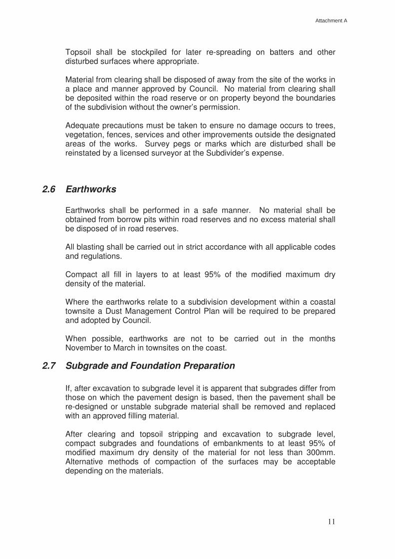
Topsoil shall be stockpiled for later re-spreading on batters and other disturbed surfaces where appropriate.
Material from clearing shall be disposed of away from the site of the works in a place and manner approved by Council. No material from clearing shall be deposited within the road reserve or on property beyond the boundaries of the subdivision without the owner’s permission. Adequate precautions must be taken to ensure no damage occurs to trees, vegetation, fences, services and other improvements outside the designated areas of the works. Survey pegs or marks which are disturbed shall be reinstated by a licensed surveyor at the Subdivider’s expense.
2.6 Earthworks Earthworks shall be performed in a safe manner. No material shall be obtained from borrow pits within road reserves and no excess material shall be disposed of in road reserves. All blasting shall be carried out in strict accordance with all applicable codes and regulations. Compact all fill in layers to at least 95% of the modified maximum dry density of the material. Where the earthworks relate to a subdivision development within a coastal townsite a Dust Management Control Plan will be required to be prepared and adopted by Council. When possible, earthworks are not to be carried out in the months November to March in townsites on the coast.
2.7 Subgrade and Foundation Preparation
If, after excavation to subgrade level it is apparent that subgrades differ from those on which the pavement design is based, then the pavement shall be re-designed or unstable subgrade material shall be removed and replaced with an approved filling material. After clearing and topsoil stripping and excavation to subgrade level, compact subgrades and foundations of embankments to at least 95% of modified maximum dry density of the material for not less than 300mm. Alternative methods of compaction of the surfaces may be acceptable depending on the materials.
Attachment A
12
2.8 Pavements
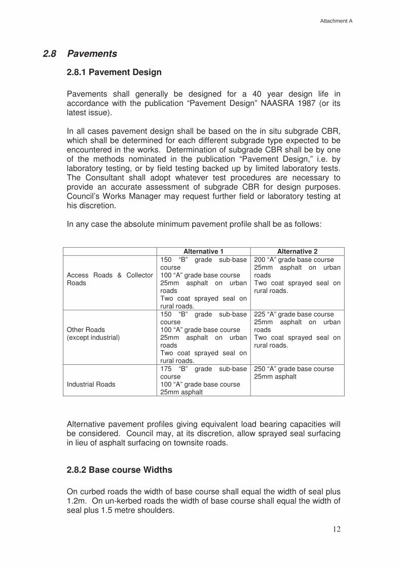
2.8.1 Pavement Design Pavements shall generally be designed for a 40 year design life in accordance with the publication “Pavement Design” NAASRA 1987 (or its latest issue). In all cases pavement design shall be based on the in situ subgrade CBR, which shall be determined for each different subgrade type expected to be encountered in the works. Determination of subgrade CBR shall be by one of the methods nominated in the publication “Pavement Design,” i.e. by laboratory testing, or by field testing backed up by limited laboratory tests. The Consultant shall adopt whatever test procedures are necessary to provide an accurate assessment of subgrade CBR for design purposes. Council’s Works Manager may request further field or laboratory testing at his discretion. In any case the absolute minimum pavement profile shall be as follows: Alternative 1 Alternative 2 Access Roads & Collector Roads
150 “B” grade sub-base course 100 “A” grade base course 25mm asphalt on urban roads Two coat sprayed seal on rural roads.
200 “A” grade base course 25mm asphalt on urban roads Two coat sprayed seal on rural roads.
Other Roads (except industrial)
150 “B” grade sub-base course 100 “A” grade base course 25mm asphalt on urban roads Two coat sprayed seal on rural roads.
225 “A” grade base course 25mm asphalt on urban roads Two coat sprayed seal on rural roads.
Industrial Roads
175 “B” grade sub-base course 100 “A” grade base course 25mm asphalt
250 “A” grade base course 25mm asphalt
Alternative pavement profiles giving equivalent load bearing capacities will be considered. Council may, at its discretion, allow sprayed seal surfacing in lieu of asphalt surfacing on townsite roads.
2.8.2 Base course Widths
On curbed roads the width of base course shall equal the width of seal plus 1.2m. On un-kerbed roads the width of base course shall equal the width of seal plus 1.5 metre shoulders.
Attachment A
13
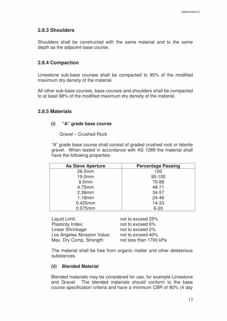
2.8.3 Shoulders Shoulders shall be constructed with the same material and to the same depth as the adjacent base course.
2.8.4 Compaction Limestone sub-base courses shall be compacted to 95% of the modified maximum dry density of the material. All other sub-base courses, base courses and shoulders shall be compacted to at least 98% of the modified maximum dry density of the material.
2.8.5 Materials
(i) “A” grade base course Gravel – Crushed Rock
“A” grade base course shall consist of graded crushed rock or laterite gravel. When tested in accordance with AS 1289 the material shall have the following properties:
As Sieve Aperture Percentage Passing 26.5mm 19.0mm 9.5mm
4.75mm 2.36mm 1.18mm
0.425mm 0.075mm
100 95-100 70-88 48-71 34-57 24-46 14-33 6-20
Liquid Limit: not to exceed 25% Plasticity Index: not to exceed 6% Linear Shrinkage: not to exceed 2% Los Angeles Abrasion Value: not to exceed 40%
Max. Dry Comp. Strength: not less than 1700 kPa The material shall be free from organic matter and other deleterious substances. (ii) Blended Material Blended materials may be considered for use, for example Limestone and Gravel. The blended materials should conform to the base course specification criteria and have a minimum CBR of 80% (4 day
Attachment A
14
soaked) and have atterburg properties that comply with the requirements of base course material, that is Non Plastic. The following minimum requirements need to be met by any blended A grade base course material and the entity that wins, places and finishes any base course pavement materials:
• Minimum CBR or 80; • Liquid Limit of 30 or less; • Plasticity Index of 6 or less; • Uniform in colour, homogenous in consistency; • Free from deleterious or other foreign matter not suitable for
road construction; • Capable of being finished to a satisfactory level and uniformity
such that a sprayed bituminous seal may be applied; and • Compacted to a minimum of 96% of the Modified Maximum
Dry Density. (iii) “B” grade sub-base course
“B” grade sub-base course shall consist of limestone or laterite gravel.
Limestone shall conform to the following requirements:
- all materials shall contain a minimum of 60% calcium carbonate; - all material shall pass through a 100mm square sieve; - not more than 80% of the material shall pass through a 75 micron
AS sieve; - all material shall be free from capstone, roots and other
deleterious substances.
Gravel shall be selected natural laterite gravel which exhibits an even grading curve throughout the full range. When tested to AS 1289 the material shall have the following properties:
- Percentage passing 40mm sieve: 100% - Percentage passing 1.18mm sieve: 10 to 50% - Percentage passing 0.075mm sieve: less than 20% - Plasticity Index: 3% to 10% - Linear Shrinkage: less than 8% - Minimum CBR at the placed in situ
moisture density condition: 35
The material shall be free from organic matter and other deleterious substances.
(iv) Asphalt
Asphalt shall be a nominal 10mm size asphaltic concrete mix in accordance with an AC10 mix designation to AS 2734.
Attachment A
15
(v) Sprayed seals
Sprayed seals shall consist of a minimum two coat seal. The first or primerseal shall be a hot sprayed bitumen primerseal, unless, with the approval of the Works Manager, a bitumen emulsion primerseal may be used. In rural residential areas, the cover aggregates shall be 14mm, followed by the second coat of 7mm metal. In areas zoned other than rural residential where a spray seal is applicable, the cover aggregate shall be 7mm and 14mm metal respectively.
2.8.6 Selection and Use of Road Pavement Material Selection and Use of Road Pavement Materials – General The use of any naturally occurring, manufactured or otherwise
blended material on any road pavement construction, maintenance or rehabilitation shall be approve by the Shire of Dandaragan, in writing, prior to any materials being blended or otherwise manufactured for deliver to any construction site within the Shire.
Without adversely impacting on all other safety, regulatory and quality
aspects of the laws and regulations administered by the Shire of Dandaragan and unless otherwise nominated or agreed in writing, the selection of raw materials for use in road pavement construction shall comply with the following criteria:
Extraction Sites Extraction sites of naturally occurring and other manufactured raw
materials, namely gravel, limestone, sand and hard rock which is proposed for use in road pavement construction shall be suitably licensed all relevant regulatory bodies and be operated within any terms as may be determined by such regulation.
Extraction of materials shall be in a systemic manner such that all
materials won, loaded, screened, crushed and stockpiled for immediate use or further blending or modification can be identified and segregated into clearly identifiable lots for the purpose of testing for suitability for use and subsequent compliance to the specification.
Sampling and classification of materials for use should be in
accordance with Australian Standard AS 1726 Geotechnical Site Investigations and Australian Standard AS 3798 Guidelines for Earthworks for Commercial and Residential Developments and AS 3727 Guide to Residential Pavements.
Attachment A
16
Details of the sampling and testing of raw materials are to be made
available to the Shire of Dandaragan prior to the extraction of any materials. Council retains the right to insist that a suitably qualified consultant or advisor be engaged to offer third party assistance in the interpretation of the sampling and test results, unless the entity extracting the materials has the capacity to perform this function from their own resources. All costs to perform the testing of materials and any third party advise or testing to be at the cost of the applicant.
Stockpilling and Storage Stockpiles and storage areas shall be of sufficient size and shape that clearly identified and segregated materials can be accessed for immediate use or further processing prior to dispatch from the extraction site. Stockpile and storage areas shall have clean and reasonably level free draining floors and a satisfactory distance between materials or suitable dividing mechanism to ensure that unplanned or unnecessary contamination does not occur while in storage. Suitable mechanical plant and equipment shall be used to perform raw material loading and blending functions with the focus on maintaining consistency of materials. Blending and Manufacture The blending and manufacture of raw materials for use in road pavement construction shall be with suitable plant and equipment such that homogenous and uniform materials are produced for delivery to construction sites. For crushed rock materials manufactured from a nominated hard rock quarry, blending and manufacture shall be performed to produce materials complying with the requirements of this specification and Main Roads WA Specification 501 Pavements. For naturally occurring materials, which after sampling and testing are found to be satisfactory for use with no additional blending or manufacturing processes, shall comply with the requirements of this specification and Main Road WA Specification 501 Pavements. For naturally occurring of manufactured materials, which after sampling and testing, require modification, blending or adjustment to comply with the requirement of this specification and Main Road WA Specification 501 Pavements, and final blend, physical performance and manufacturing details shall be submitted to the Shire of Dandaragan for approval prior to delivery to construction sites within the Shire.
Attachment A
17
The purpose of seeking approval for blended products is so that the Shire may gain confidence that the proposed blend or modified materials will suit the requirements of the physical properties for road pavement materials in this specification. Council intends to utilise blended mixtures as an option for base course materials as access to high quality raw material resources may occasionally be restricted, it is in the best interests of the Shire and those who propose to use raw materials for road pavement construction to enable the use of blended materials where it is impracticable or commercially unviable for crushed hard rock or conforming naturally occurring materials to be used. Identification, Sampling and Testing after Blending or Manufacture After extraction, stockpiling, storage, blending and manufacture all materials shall be sampled and tested at the frequencies and to the test methods as nominated in this specification. No material will be accepted for use on site without the following being available or in place prior to delivery to site:
• Clearly identifiable stockpiles or lots of recorded sizes of CONFORMING material;
• Representative test results as nominated in this specification; and
• Record of quality loaded at the stockpile or storage area, such as a delivery docket.
Loading and Delivery Loading and delivery of materials in the stockpile or storage area shall only be from CONFORMING stockpiles or lots. No material that are considered to be NON CONFORMING with this specification shall be loaded or delivered to site for use in road pavement construction. Stockpilling and Storage on the Construction Site After delivery to site the material to be used for road pavement construction shall be segregated from all other construction materials and similarly any road pavement material which is not from the same source or of the same type, such as base course and sub base course material, shall also be kept separate. The uniformity of the material must be maintained at all times and activities such as moisture conditioning and grading shall be performed at intervals and in a manner that maintains the homogeneity of the road pavement materials.
Attachment A
18
Compaction and Finishing The surface finish and effective compactive effort applied to the road pavement shall be such that no layer or thickness of material is able to easily separated or delaminated from the layer or thickness. The road pavement finish and final geometry shall be compliant with the requirements of this specification. Conformance sampling and testing of the sub base and base course materials shall be in accordance with the requirements of this specification. Measurment Measurement of road pavement materials delivered to sites shall be tonnes or cubic metres. Tonnage figures are to be from a registered and calibrated weighbridge or load meter or based on a calculated figure derived from a representative traceable and independent assessment of the density and volume properties of the raw or blended materials.
2.9 Kerbing
All concrete kerbing shall be machine extruded to profiles approved by Council’s Works Manager. Concrete for kerbing shall be N25 grade central batch mixed concrete. Provide a base key 150mm wide x 75mm deep under all kerbing laid to a radius of 30m or less. Provide contraction joints at 2m intervals and full depth expansion joints at 6m intervals. Kerbing shall be laid accurately to line and level with continuous reference to string lines set for both line and grade.
2.10 Stormwater Drainage
2.10.1 General
Stormwater drainage systems are requited to provide for effective disposal of stormwater and shall be designed using methods in accordance with “Australian Rainfall and Runoff.” The rainfall intensity for a calculated time of concentration and recurrence interval shall be determined from the
Attachment A
19
Design Rainfall Intensity Diagram for the area prepared by the Bureau of Meteorology.
2.10.2 Common Catchments Subdividers with land in a common catchment area have a joint responsibility to ensure that the whole catchment area (including arterial roads) will be served by an effective drainage system. When only a portion of a catchment is being developed at a particular time the drainage strategy for the whole catchment area should be determined. Subdividers are responsible for arranging their own cost sharing arrangements. The Subdivider shall provide, at his cost, the necessary pipework and system capacity to carry stormwater from arterial road reserves. Manholes or other drainage facilities shall be provided at the edge of the arterial road reserve to serve as connection points between the subdivision drainage system and the arterial road drainage system where applicable.
2.10.3 Recurrence Intervals & Run-off Coefficients Design recurrence intervals shall be as follows: Residential areas: 1 in 5 years Industrial areas: 1 in 10 years Rural areas: 1 in 10 years At local low points where flood routing is not available: 1 in 20 years Arterial drainage lines: 1 in 10 years The total area contributing should be analysed and run-off coefficients assigned to each contributing sub-area. A run-off coefficient of 0.85 shall be used for all commercial and industrial areas unless otherwise approved by Council’s Works Manager.
2.10.4 Provision for Flooding In all cases provision shall be made via overland flow paths and/or storage for the maximum flood resulting from a 1 in 100 year recurrence interval. In all cases the 1 in 100 year flood level shall not reach a level of less than 500mm from finished floor levels.
Attachment A
20
2.10.5 Pipe Types The following pipe types shall be permitted: Townsite areas: reinforced concrete pipes (and boxes) in classes
appropriate to loadings and cover heights: aluminium Hel-Cor pipes with a minimum cover of
600mm. Rural Areas: reinforced concrete pipes (and boxes) in classes
appropriate to loadings and cover heights; steel and aluminium Hel-Cor pipes with a minimum
cover of 600mm. Other types of pipes shall be approved by Council’s Works Manager.
2.10.6 Underground Pipe Systems
The minimum pipe size shall be 225mm diameter and the minimum pipe size under roads shall be 300mm diameter.
Pipelines shall be designed to ensure that hydraulic grade lines do not reach a level of less than 150mm from finished surface levels for the design recurrence interval.
The velocity in pipes shall be limited to the range 1.0 m/sec – 6.0 m/sec. The possibility of scour at outfalls shall be considered and steps taken to eliminate it where it may occur.
Manholes shall be provided at each change in direction and at maximum 90m spacings.
Inlet pits shall be placed at low points and at the upstream side of intersections if warranted by flow considerations. Inlet pits shall also be placed at intervals to limit the width of gutter flow to 1.5m (or 2.0m in the case of one-way crossfall), in kerbed roads, and at intervals to prevent the top water level in the table drain from rising to within 200mm of the edge of the shoulder in the case of un-kerbed roads, or to limit the inflow to the entry pit to its inlet capacity, whichever is the least, for the design recurrence interval flows. On kerbed roads side entry pits shall be used, although combined side entry/grated pits may also be used. On un-kerbed roads, any concrete catchpits situated in table drains shall have grated tops at least 150mm above entry lips to prevent access to the pit by the public.
Attachment A
21
All outlets to pipe drainage systems (and inlets in the case of open ended culverts) shall have concrete headwalls with concrete aprons, and shall have anti-scour rock beaching for a minimum distance of 2m beyond the edge of aprons. All trenches for pipes laid under road pavements shall be backfilled to the pavement subgrade surface with clean sand or road base course material. The material shall be placed in even layers not exceeding 300mm in thickness and each layer shall be compacted with a minimum of four (4) passes of a vibratory plate compactor having a minimum static mass of 50kg. Care should be taken to ensure that the material fills all voids under the haunches and that no damage occurs to the pipe whilst compacting material next to and immediately over the pipe. The clean sand shall preferably be supplied from a central batch mixing plant.
2.10.7 Open Drains Where drainage is by means of open drains, allowances must be made for access culverts to properties although they may not need to be provided at the development stage. Where pipe sizes required for crossover culverts exceed 375mm diameter, they shall be provided by the Subdivider. All culverts shall have adequate concrete headwalls and drain scour protection – refer Section 2.10.6. Where pre-cast headwalls are used, the finished level of the headwall shall not project more than 100mm above the adjacent pavement level. Table drains to un-kerbed roads shall be sized so that the top water level in a drain does not rise to within 200mm of the edge of the shoulder for the design recurrence interval flow. Installation of catchpits is at the discretion of Council’s Works Manager. Culverts may be utilised to contain flows in table drains within permissible limits where applicable – refer Section 2.10.6. Where there is a risk of scouring in open drains (including table drains), the drains shall be fully lined with a lining of rock, concrete or other method approved by Council’s Works Manager.
2.10.8 Sub-Soil Drains Where sub-soil water is present, or is likely to become present at any time, and is likely to interfere with the stability of the road pavement (or footpath or access-way etc) a system of sub-soil drainage shall be designed and installed to the approval of Council’s Works Manager.
Attachment A
22
Sub-soil drains shall be installed to cut off flows at least 600mm clear of any surface of the pavement and shall discharge to piped drainage systems or open drains downstream of the affected area, as appropriate for each situation.
2.10.9 Drainage Easements Where drains cross private property they shall be laid in registered easements which shall show on all plans. The easement shall be centrally located over the drainage line and it shall have a width of at least twice the depth of the drain with an absolute minimum width of 3.0m. 2.10.10 Water Pipes Under Roads (stock or domestic supplies) – Rural
Areas The Chief Executive Officer is authorised to approve applications to install water pipes under roads subject to the following:
1) Water pipes to be placed at least 0.6 meters below the shoulder level of the road.
2) Water pipes to be encased (sleeved in PVC or steel pipe) for 13 metres (ie 6.5metres from the centre of the roadway).
3) The alignment of the water pipe under the road is to be defined by suitable markers.
4) The applicant to meet the total cost of re-instating the roadway to Council’s specifications.
5) The applicant to indemnify Council from any damage caused by the installation of the water pipe under the roadway.
6) The trench for the water pipe is to be installed by appropriate machinery to keep the disturbance to the roadway to a minimum.
7) If water pipe crosses adjacent private property, written confirmation is to be provided to Council from all property owners affected by the installation of the water pipe.
8) This site is to be inspected by Council officers prior to the commencement of any work.
9) The applicant to be responsible for the location of all affected services, eg Telstra, Water, etc.
2.11 Miscellaneous Facilities
2.11.1 Footpaths Footpaths in road reserves shall be provided in town-site residential
subdivisions unless special circumstances prevail in which case they may be omitted at Council’s discretion. If footpaths are required they shall be provided at the Subdivider’s cost. It footpaths are required Council may
Attachment A
23
wish to defer construction until the majority of houses fronting the street are constructed to enable driveway crossings to be located. In this case the Subdivider shall pay to Council the estimated cost of deferred footpath construction (as estimated by Council) in lieu of constructing the footpaths.
Where footpaths are to be provided by the Subdivider they shall be 2m in
width x 100mm thick concrete paths with a 2% slope towards kerbs (or edge of roadways). Tooled contraction joints shall be provided at 2m intervals and 12mm wide full depth expansion joists shall be provided at 6m intervals. The surfaces of concrete footpaths shall have a non-slip broomed finish.
2.11.2 Signs and Guide Posts All direction or warning signs and guide posts shall be erected in
accordance with AS 1742.5 – 1986. Requirements for such signs shall be clearly shown on the drawings.
2.11.3 Street Nameplates Street Nameplates shall be erected at all newly created intersections and shall indicate the names of both streets. Nameplates shall generally be in accordance with AS 1742.5 – 1986 and shall incorporate any special feature which may be required by Council (eg Shire logo, colours or legend and background etc – see attachment No. 1). Depth of sign shall be 150mm with 100mm lettering (see attachment No.1) Signs shall be mounted at a height of three (3) metres above finished ground level. If two or more signs are to be erected on the same pole they shall be erected at differing levels. Nameplates shall be mounted on a 50mm nom. Bore galvanised flat round steel pole concreted a minimum of 600mm into the ground. The pole shall be erected on the 2.7m alignment with anti-theft locking units. 2.11.4 Battle-Axe Access Roads Access road pavement to battle-axe blocks shall not be less than three metres wide and centrally located for the full length of the access way. Special consideration shall be given to “reciprocal rights” access ways which will require greater road pavement width. The design, shape, width and drainage of these access-ways shall be to the approval of Council.
2.11.5 Crossovers in Special Rural Lots
1. This specification details the minimum requirements for the construction
of vehicle crossovers to Special Rural properties.
Attachment A
24
2. Particular care must be taken to locate and protect any public utility, survey marks or other property. Should any public utility, survey mark or other property be located on the proposed alignment of the crossover the property owner shall be responsible for the costs associated with removals or alterations of such.
Where crossovers are constructed privately, the property owner shall cause any damage to public utilities, survey marks or other property to be made good at his expense.
3. The crossover shall generally conform to the levels of the verge and the road formation. The level from the property line to the back of the kerb shall be minus 2% grade. Where there is no kerb, an allowance is to be made for kerbing to height of 130mm above bitumen.
4. The crossover shall be constructed at right angles to the road formation and located no less than 4.5m from an adjoining property. No portion of the crossover shall enter the road verge immediately in front of an adjoining property.
5. The crossover dimensions shall be in accordance with drawing DN-04. 6. The site of the crossover shall be cleared of all roots, trees and any
other vegetation or rubbish. Where in the opinion of the Works Manager the in-situ sub-base material is of inadequate strength and / or drainage, the site of the crossover shall be boxed out to a depth of no less than 100mm. The formation shall then be formed to the levels and gradients required and consolidated.
7. The crossover shall be constructed from well graded gravel, or crushed road base, free of organic matter, balls or lumps or clay or other deleterious substances.
8. The crossover material shall be laid on the formed sub-base to a minimum thickness of 100mm, compacted and water bound until a slurry forms on the surface. This slurry shall be removed to form a smooth, compacted surface.
9. The crossover shall have a minimum 300mm diameter stormwater
culvert for the full width of the crossover. This culvert shall be a reinforced concrete pipe (RCP) and shall be installed parallel and offset to the table drains as determined by the Works Manager.
No exceptions to this condition will be allowed except with the written approval of the Works Manager.
10. Culvert ends shall be finished with precast end walls or formed concrete end walls.
Attachment A
25
Formed concrete shall have a minimum compressive strength of 20Mpa at twenty-eight (28) days. Where possible the end walls shall be shaped in accordance with drawing DN-04. All end walls shall be backfilled and left neat and presentable.
11. Where owners of adjacent properties wish to construct a dual crossover, the construction principle and methods above shall prevail and the dimensions and location shall be determined by the Works Manager with a standard minimum of 9m wide and a pipe 9.6m.
12. Upon completion the verge shall be left level and in a neat and safe
condition. 2.11.6 Crossovers in Rural Lots 1. This specification details the minimum requirements for the construction
of vehicle crossover to Rural properties. The need for a pipe and precast headwalls will be at the discretion of the Works Manager.
2. Particular care must be taken to locate and protect any public utility,
survey marks or other property. Should any public utility survey mark or other property be located on the proposed alignment of the crossover the property owner shall be responsible for the costs associated with removals or alterations of such.
Where crossovers are constructed privately, the property owner shall cause any damage to public utilities, survey marks or other property to be made good at his expense.
3. The crossover shall generally conform to the levels of the verge and the road formation. The level from the property line to the back of the kerb shall be minus 2% grade. Where there is no kerb, an allowance is to be made for kerbing to a height of 130mm above bitumen.
4. The crossover shall be constructed at right angles to the road formation
and located no less than 6m from an adjoining property. No portion of the crossover shall enter the road verge immediately in front of an adjoining property.
5. The crossover dimensions shall be in accordance with drawing DN-05. 6. The site of the crossover shall be cleared of all roots, trees and any
other vegetation or rubbish.
Where in the opinion of the Works Manager the in-situ sub-base material is of inadequate strength and / or drainage, the site of the crossover shall be boxed out to a depth of no less than 100mm. The formation
Attachment A
26
shall then be formed to the levels and gradients required and consolidated.
7. The crossover shall be constructed from well graded gravel, or crushed road base, free of organic matter, balls or lumps or clay or other deleterious substances.
8. The crossover material shall be laid on the formed sub-base to a minimum thickness of 100mm, compacted and water bound until a slurry forms on the surface. This slurry shall be removed to form a smooth, compacted surface.
9. The crossover shall have a minimum 300mm diameter stormwater
culvert for the full width of the crossover. This culvert shall be a reinforced concrete pipe (RCP) and shall be installed parallel and offset to the table drains as determined by the Works Manager.
No exceptions to this condition will be allowed except with the written approval of the Works Manager.
10. Culvert ends shall be finished with precast end walls or formed concrete end walls or stone pitching. Formed concrete shall have a minimum compressive strength of 20Mpa at twenty-eight (28) days. Stone pitched end walls shall be constructed of hard, sound and durable stone with the joints grouted and left clean. Where possible the end walls shall be shaped in accordance with drawing DN-05. All end walls shall be backfilled and left neat and presentable.
11. Upon completion the verge shall be left level and in a neat and safe condition.
2.11.7 Vehicle Crossovers to Commercial / Industrial
1. This specification details the minimum requirements for the construction of Industrial vehicle crossover.
2. Particular care must be taken to locate and protect any public utility,
survey marks or other property. Should any public utility survey mark or other property be located on the proposed alignment of the crossover the property owner shall be responsible for the costs associated with removals or alterations of such.
Where crossovers are constructed privately, the property owner shall cause any damage to public utilities, survey marks or other property to be made good at his expense.
Attachment A
27
3. The crossover shall generally conform to the levels of the verge and the
road formation. The level from the property line to the back of the kerb shall be minus 2% grade. Where there is no kerb, an allowance is to be made for kerbing to a height of 130mm above bitumen.
4. The crossover shall be constructed at right angles to the road formation
and located no less than 2.0m from an adjoining property. No portion of the crossover shall enter the road verge immediately in front of an adjoining property.
5. The crossover dimensions shall be in accordance with drawing DN-06. 6. Where fully mountable kerbing is cast, the crossover is to be constructed
without removing the kerb.
7. Where barrier or semi-mountable kerbing is cast, the kerb shall be cut using a concrete saw and removed for the width of the crossover and made good upon completion of the crossover.
8. Where a slabbed footpath exists, the slabs shall be removed, cut and re-laid as necessary to match the crossover levels.
9. Where a concrete footpath exists, the footpath is to be cut using a
concrete saw and removed and re-laid as necessary to match the crossover levels. A 10mm expansion joint must be installed between the footpath and the crossover.
10. The site of the crossover shall be cleared of all roots, trees and any
other vegetation or rubbish. The site of the crossover shall be boxed out to a depth of no less than 200mm. The formation shall then be formed to the levels and gradients required and compacted. The excavation shall be free from depressions, soft spots or any deleterious materials. The sub-base shall be thoroughly moistened prior to pouring of any concrete.
11. All concrete used in the works shall have a minimum compressive strength of 20Mpa at twenty-eight (28) days and have a maximum slump of 75mm.
12. The concrete shall be evenly poured to a minimum thickness of 200mm with F63 reinforcement mesh included with 25mm cover.
13. The finish shall be obtained by screeding to correct levels and broom
swept to provide a non-slip dense surface free from any defects. The concrete may be coloured to owners requirements.
Attachment A
28
14. 10mm expansion and 5mm contraction joints shall be provided in accordance with drawing DN-08.
Expansion joints shall be filled with polyethylene foam packer and shall be provided at the boundary line and behind existing mountable kerbing.
15. Where owners of adjacent properties wish to construct a dual crossover, the construction principle and methods outlined above shall prevail and the dimensions and location shall be determined by the Works Manager. No dual crossover shall be constructed without the written approval of the Works Manager.
16. Upon completion the verge shall be left level and in a neat and safe condition.
2.11.8 Vehicle Crossovers to Urban Residential Lots
1. General 1.1 This specification details the minimum requirements for the
construction of vehicle crossovers to Urban Residential properties.
1.2 This specification does not apply to commercial applications were vehicle traffic loadings are in excess of domestic traffic.
1.3 Particular care must be taken to locate and protect any public
utility, survey marks or other property. Should any public utility survey mark or other property be located on the proposed alignment of the crossover the property owner shall be responsible for the costs associated with removals or alterations of such.
Where crossovers are constructed privately the property owner shall cause any damage to public utilities, survey marks or other property to be made good at his expense.
1.4 The crossover shall general confirm to the levels of the verge and the road formation. The level from the property line to the back of the kerb shall be minus 2% grade.
Where there is no kerb an allowance is to be made for kerbing to a height of 130mm above bitumen.
1.5 Notwhithstanding Condition 1.10 the crossover shall be constructed at right angles to the road formation and located no less than 2.0m from an adjoining property. No portion of the crossover shall enter the road verge immediately in front of an adjoining property.
Attachment A
29
1.6 Where fully mounted kerbing is cast, the crossover is to be
constructed without removing the kerb.
1.7 Where barrier or semi-mountable kerbing is cast, the kerb shall be cut using a concrete saw and removed for the width of the crossover and made good upon completion of the crossover.
1.8 Where a slabbed footpath exists, the slab shall be removed, cut
and re-laid as necessary to match the crossover levels.
1.9 Where a concrete footpath exists, the footpath is to be cut using a concrete saw and removed and re-laid as necessary to match the crossover levels. A 10mm expansion joint must be installed between the footpath and the crossover.
1.10 Where owners of adjacent properties wish to construct a dual
crossover, the construction principle and methods outlined above shall prevail and the dimensions and location shall be determined by the Works Manager.
1.11 Upon completion the verge shall be left level and in a neat and
safe condition.
2. Concrete Crossovers
2.1 The crossover shall be constructed in accordance with these
specifications and drawing DN-01.
The crossover dimensions shall be in accordance with drawing DN-01
2.2 The site of the crossover shall be cleared of all roots, trees and any
other vegetation or rubbish.
The site of the crossover shall be boxed to a depth of no less than 100mm. The formation shall then be formed to the levels and gradients required and compacted. The excavation shall be free from depressions, soft spots or any deleterious materials. The sub-bas shall be thoroughly moistened prior to pouring of any concrete.
2.3 All concrete used in the works shall have a minimum compressive strength of 20Mpa at twenty-eight (28) days and have a maximum slump of 75mm.
2.4 The concrete shall be evenly poured to a minimum thickness of
100mmj with F63 reinforcement mesh included with 25mm cover.
Attachment A
30
2.5 The finish shall be obtained by screeding to correct levels and
broom swept to provide a non-slip dense surface free from any defects. The concrete may be coloured to owners requirements.
2.6 10mm expansion and 5mm contraction joints shall be provided in
accordance with drawing DN-02.
Expansion joints shall be filled with a polyethylene foam packer and shall be provided at the boundary line and behind existing mountable kerbing.
Brick Paving Crossovers
2.7 The crossover shall be constructed in accordance with these specifications and drawing DN-02.
The crossover dimensions shall be in accordance with drawing DN-002.
2.8 The site of the crossover shall be cleared of all roots, trees and any other vegetation or rubbish.
The site of the crossover shall be boxed out to a depth of no less than 100mm. The formation shall then be formed to the levels and gradients required and compaction. The excavation shall be fee from depressions, soft spots or any deleterious materials.
2.9 Paving bricks shall be a minimum of 60mm thick and laid on a bed of building sand no less than 30mm thick.
2.10 The edges if the crossover shall be retained using header course
mortared together.
Where the existing kerbing has been removed a 150mm x 150mm concrete foundation shall be laid across the full width of the crossover, at levels such that the brick paving finishes flush with the bitumen level.
2.11 A 45� or 90� herringbone pattern is preferred.
2.12 Unless specifically detailed in this specification, all practices and materials to be used as specified in the brick manufacturers recommendation.
Bitumen Crossovers
2.13 The crossover shall be constructed in accordance with these
specifications and drawing DN-03.
Attachment A

31
The crossover dimensions shall be in accordance with DN-03.
2.14 The site of the crossover shall be cleared of all roots, trees and any other vegetation or rubbish.
The site of the crossover shall be boxed out to a depth of no less than 100mm. The formation shall then be formed to the levels and gradients required and compaction. The excavation shall be free from depressions, soft spots or any deleterious materials.
2.15 The crossover base shall be constructed from well graded gravel, or crushed road base, free of organic matter, balls or lumps of clay or other deleterious substances.
2.16 The crossover shall be kerbed using 100mm x 50mm quality jarrah. The kerbing shall be installed on both sides of the crossing, including sweeps, from the boundary to the kerb or road shoulder.
The kerbing shall be supported by 50mm x 50mm x 300mm jarrah pegs at maximum 1.5m spacings. The kerbing shall finish flush with the final bituminous surface.
2.17 The base material shall be laid on the formed sub-base to a
minimum thickness of 100mm, compacted and water bound until a slurry forms on the surface. This slurry shall be removed to leave a smooth, compacted surface.
2.18 The base shall be lightly moistened prior to applying a tack coat.
2.19 The bituminous surface shall be an approved emulsion bitumen with medium curing cutter or asphalt.
2.20 The bituminous surface shall be sprayed by an approved operator
with the approved equipment.
HOT BITUMINOUS PRODUCTS CAN BE DANGERIOUS!
2.21 The cover material shall be 7mm uniformly graded granite, diorite or laterite. The cover material shall be worked to produce a fine, dense, smooth surface free of voids.
2.11.9 Fencing for subdivisions outside of townsites Fencing for subdivisions outside of designated townsites shall be constructed in accordance with Council’s specifications (see photos in attachment No. 2).
Attachment A
32
(1) In the case of a non-electrified fence, a sufficient fence on a Rural lot is a fence of posts and wire construction, the minimum specifications for which are:
(a) wire shall be high tensile wire and not less than 2.5mm. A
minimum of five wires shall be used, generally with the lower wires spaced closer together than the higher wires so as to prevent smaller stock passing through, and connected to posts in all cases;
(b) posts shall be of indigenous timber or other suitable
material including
- timber impregnated with termite and fungicidal preservative;
- standard iron star pickets; or - concrete
(c) if timber posts are used, posts are to be cut not less than
1800mm long x 50mm diameter at small end if round or 125mm x 60mm if split or sawn. Posts to be placed at not more than 10 metre intervals, set minimum 600mm in the ground and 1200mm above the ground; and
(d) strainer posts, if timber, shall be not less than 2250mm
long and 150mm diameter at the small end (tubular steel to be 50mm in diameter) and shall be cut from the indigenous timber of other suitable material. These shall be placed a minimum of 1000mm in the ground and set at all corners, gateways and fence line angles but not exceeding 200 metres apart.
(2) An electrified fence having four wires is only a sufficient fence if
constructed generally in accordance with (1)
2.11.10 Provision for School Bus Facilities
Provision for school bus facilities shall be allowed for in the development of Special Rural or Rural Developments. For specifications see attachment No. 3. Consultation will need to be carried out with Council and the local school regarding a suitable area for the construction of the School Bus Facility incorporating a shelter and suitable parking/let down area. If the development of land is to be staged consideration may be given for the deferral of the facility subject to the provision of funds equal to the cost of construction.
Attachment A
33
3. SUBMISSION REQUIREMENTS
3.1 General
Two copies of design drawings, specifications and drainage and pavement calculations shall be submitted for approval by Council. Any amendments will be marked up on one copy which shall be returned to the Consultant. Three copies of amended drawings and specifications shall then be re-submitted by the Consultant. One copy of approved drawings and specifications shall be signed by a Council Officer and marked “Approved for Construction” and shall be returned to the Consultant together with any conditions imposed on the approval. No construction shall commence until “approved for construction” drawings are certified in writing by Council.
3.2 Drawings
Drawings as detailed in 3.5 are required to be submitted for approval. If considered necessary by Council, information, details and/or drawings additional to those listed shall be provided.
3.3 Drainage Calculations
Submit drainage calculations for approval for every underground drain and all open drains (except table drains) including bridges, pipe drains, box culvert drains etc. Calculations shall show catchment areas, run-off coefficients, recurrence intervals, rainfall intensities, times of concentration and method of sizing drains. Calculations shall be set out in a standard tabular format or approved format to facilitate checking.
3.4 Pavement Calculation
Submit pavement calculations for approval. Calculations shall show the method adopted for calculation of subgrade CBR including test results, design pavement life, design traffic loadings, determination of base course thicknesses and need for subgrade stabilisation/improvement where necessary. Provide copies of all subgrade tests.
Attachment A

34
3.5 Required Drawings
Drawing Scales Information to be Shown Locality Plan Min. 1:50 000 Site of the works, existing
roads including major arterial roads, locality areas and other significant features.
Pre-calculated Plan Min.1:2 000 All cadastral information relating to lots, roads, easements, accessways etc.
Layout Plan Min. 1:1 000 New roads and existing roads to which they are connected. Details of new road alignments and curves. Existing services and structures (power poles, water mains, Telstra cables, fences, drains etc). New drains, culverts and drainage structures. New footways, cycleways, accessways etc. advance warning signs and other traffic signs.
Longitudinal Sections of each road
Min. 1:2 000 horiz. and 1:200 vert. (or larger scales in the same proportions)
Design centreline levels at max. 20m intervals (10m on vertical curves). Natural surface levels at max. 20m intervals, location of horizontal curves and super-elevation details, location of drainage culverts.
Cross Sections of each road Min. 1:200 horiz. and 1:100 vert. (or larger scales in the same proportions)
At max. 20m intervals: Natural surface extending from property line to property line; Design surface including boxing for base courses showing crossfalls; Design and natural surface levels on the centreline of the road.
Road Intersection & cul-de-sac treatments
1:200 Lot boundaries, footpaths, channelisation, islands and medians, kerbing, drainage details, design spot levels along pavement edges and centreline referenced by set-out dimensions where necessary.
Standard Details Typical cross-sections for each different cross-section type (min. 1:100 horiz., 1:50
Attachment A
35
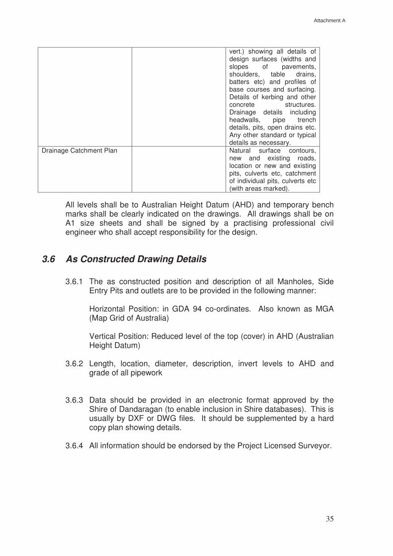
vert.) showing all details of design surfaces (widths and slopes of pavements, shoulders, table drains, batters etc) and profiles of base courses and surfacing. Details of kerbing and other concrete structures. Drainage details including headwalls, pipe trench details, pits, open drains etc. Any other standard or typical details as necessary.
Drainage Catchment Plan Natural surface contours, new and existing roads, location or new and existing pits, culverts etc, catchment of individual pits, culverts etc (with areas marked).
All levels shall be to Australian Height Datum (AHD) and temporary bench marks shall be clearly indicated on the drawings. All drawings shall be on A1 size sheets and shall be signed by a practising professional civil engineer who shall accept responsibility for the design.
3.6 As Constructed Drawing Details
3.6.1 The as constructed position and description of all Manholes, Side Entry Pits and outlets are to be provided in the following manner:
Horizontal Position: in GDA 94 co-ordinates. Also known as MGA (Map Grid of Australia) Vertical Position: Reduced level of the top (cover) in AHD (Australian Height Datum)
3.6.2 Length, location, diameter, description, invert levels to AHD and grade of all pipework
3.6.3 Data should be provided in an electronic format approved by the Shire of Dandaragan (to enable inclusion in Shire databases). This is usually by DXF or DWG files. It should be supplemented by a hard copy plan showing details.
3.6.4 All information should be endorsed by the Project Licensed Surveyor.
Attachment A
36
4. CONTROL & SUPERVISION OF CONSTRUCTION
4.1 General
All subdivision works shall be designed and constructed in accordance with sound engineering principles and in compliance with the approved drawings and specifications.
Final approval for the works shall only be given when the whole of the works shown on the drawings of subdivision have been executed to the true intent and meaning of the approved drawings and specifications and to the satisfaction of Council.
4.2 Responsibility for Quality of Construction
Irrespective of any approvals given by Council, the Subdivider and his responsible agents (including where applicable the Consulting Engineer and/or the Contractor) shall remain fully responsible for the quality of the works. The inspections, checks and tests to be carried out by Council’s Works Manager are not intended to take the place of comprehensive superintendence of the works by the Subdivider’s Consulting Engineer.
All subdivision works shall be subject to the provisions of AS 2990 “Quality Systems for Engineering and Construction Projects” and AS 3900 to 3904 “Quality Systems.” The quality assurance category to be adopted should be Category C generally with only critical aspects to be subject to Category B requirements. The Consultant shall ensure that all contract work complies with these provisions.
4.3 Schedule of Inspections
Inspections by a Council representative shall be required at the following stages of construction. A minimum of 48 hours notice shall be given by the Subdivider’s Consultant that inspections are required:
(a) On completion of foundation and subgrade preparation and prior to
placing any fill and base courses;
(b) After laying of drainage pipes (and culverts) and prior to backfilling trenches;
(c) On completion of each of the base courses and in particular
immediately prior to surfacing of base courses;
(d) During application of base course surfacing;
Attachment A
37
(e) During laying of concrete kerbing; (f) On practical completion of all of the subdivision works including
survey lot pegging and stabilsation.
No second or follow up stage of construction shall proceed until approval has been given for the preceding stage.
Representatives of the Consultant and the Contractor shall be present at stage inspections if requested by Council’s Works Manager.
4.4 Testing & As Constructed Surveys
All test results and as constructed surveys taken during the works, whether required under this part or not, shall be made available to Council’s Engineer. All materials and compaction tests shall be carried out by a NATA approved testing laboratory. All as constructed surveys shall be carried out by an independent licensed surveyor. Works which fail to meet specified criteria shall be corrected and re-tested or re-surveyed, as the case may be. The following minimum tests shall be required:
(a) Grading and testing of properties of representative samples of sub-
base and base course materials prior to commencement of supply of those materials;
(b) In situ density testing -
embankment filling: 4 tests per 1000m³
sub-base & base course 4 tests per 500m³
Additional density tests of foundation and subgrade to road pavements shall be taken at the Subdivider’s cost when requested by Council’s Engineer.
The following minimum as constructed surveys shall be required:
(a) After completion of subgrade preparation and prior to cartage of base
courses, take levels at no greater than 20m intervals on the centreline and on both edges of pavement boxing. The as constructed information shall be presented in plan or tabular form showing the chainage, the design subgrade levels for each point, the as constructed levels and the difference between the two.
(b) After completion of sub-base course construction and base course
construction, and prior to surfacing (sealing), take levels at no greater than 20m intervals in the centreline (at chainages to match subgrade levels) and on both edges of base course. The as constructed information shall be presented in plan or tabular form showing the chainage, the design base course levels for each point, the as constructed levels and the difference between the two.
Attachment A

38
(c) Pipe drain systems and open drains (not including table drains).
Details shall include location and size of pipes and drains, length between ends (or centreline distances to pits etc), lid or cover levels where appropriate, and invert levels at ends. For open drains bottom widths, invert levels at no greater than 20m intervals and side slopes shall additionally be required.
4.5 Practical Completion
Any items of work found to require rectification at the time of the practical completion inspection, or at any time thereafter shall be rectified before practical completion will be certified by the Council representative.
When all subdivisional works are completed to the satisfaction of Council, the Consultant shall be notified of the practical completion date. If at any time after the granting of practical completion the subdivisional work is found to be contrary to Council’s requirements, or si found to have been constructed in error to the approved drawings, specifications and any instructions which may have been issued by the Consultant or Council during the course of construction, then the works shall be rectified at no cost to the Council. Minor rectification items may be undertaken at the completion of the maintenance period.
Attachment A
39
5 MAINTENANCE AND RELEASE
5.1 Survey Release
Council is to be satisfied that the Subdivider has complied with all relevant conditions imposed by the Western Australian Planning Commission pertaining to survey release of all or part of a contracted subdivision.
The conditions which must be complied with by the Subdivider prior to the Council’s approval of survey release of a subdivision shall include, but shall not necessarily be limited to, the following:
(a) Creation and location of all stormwater drainage easements;
(b) Creation of any other easements (temporary or permanent) which are
relevant to the subdivision; (c) Creation of all reserves (including drainage and recreation reserves)
pertaining to the subdivisional works; (d) Payment of all monies required to be paid to the Council in
consideration of construction of footpaths, footways or any other works associated with the subdivision and which are to be carried out by the Council;
(e) Payment of any maintenance retention money (or lodgement of bank
guarantees) and payment of supervision fees required by the Council; (f) Stabilisation of topsoil, sand or other material or matter subject to
movement over or near the subdivision shall be completed to the satisfaction of Council’s Works Manager;
(g) Completion of all roadworks and other works associated with the
subdivision shall be completed to the satisfaction of Council’s Works Manager;
(h) Such drawings shall be on a reproducible material, and show the
location of all drains and services.
5.2 Maintenance
A twelve months defects liability period shall apply from the date of practical completion of the subdivisional works.
During the period the Subdivider and/or his responsible agents shall be responsible for rectification of any defects, whether they are construction or design defects, which may become apparent. The Subdivider or his
Attachment A
40
responsible agents shall carry out rectification work within the time requested by the Council representative when notified of such defects.
If defects are not rectified within the time required by Council then Council may have the defects rectified at the Subdivider’s expense. In this case the cost of the work shall become a debt due to the Council and Council may draw on any retention money or bank guarantee being held, without reference to or approval from the Subdivider and without limiting its right to recover any balance of money due should the security be insufficient to cover the costs of the works.
Before practical completion is granted the Subdivider shall lodge with the Council an amount of 5% of the cost of the works as security for ensuring the rectification of defect, which shall be retained by Council for the duration of the defects liability period. Alternatively, a bank guarantee of approved form may be lodged in lieu of retention money.
The bank guarantee shall contain clauses where the bank shall guarantee to pay to Council unconditionally on demand any amount up to the total amount of the guarantee at any time so requested, and that the guarantee shall not be withdrawn until notified by Council (i.e. it shall not have a termination date). Any bank guarantee lodged with the subdivider by a contractor in lieu of retention money shall be acceptable as part or full security (as the case may be provided it is in a form which is acceptable to Council). Any defects rectified during the defects liability period shall be subject to a further 12 months defects liability period. During this further period Council may, at its discretion, withhold the release of all or part of any security. Retention money or bank guarantee shall only be released at the expiration of the defects liability period (or any further period) after satisfactory rectification of all defects.
Attachment A
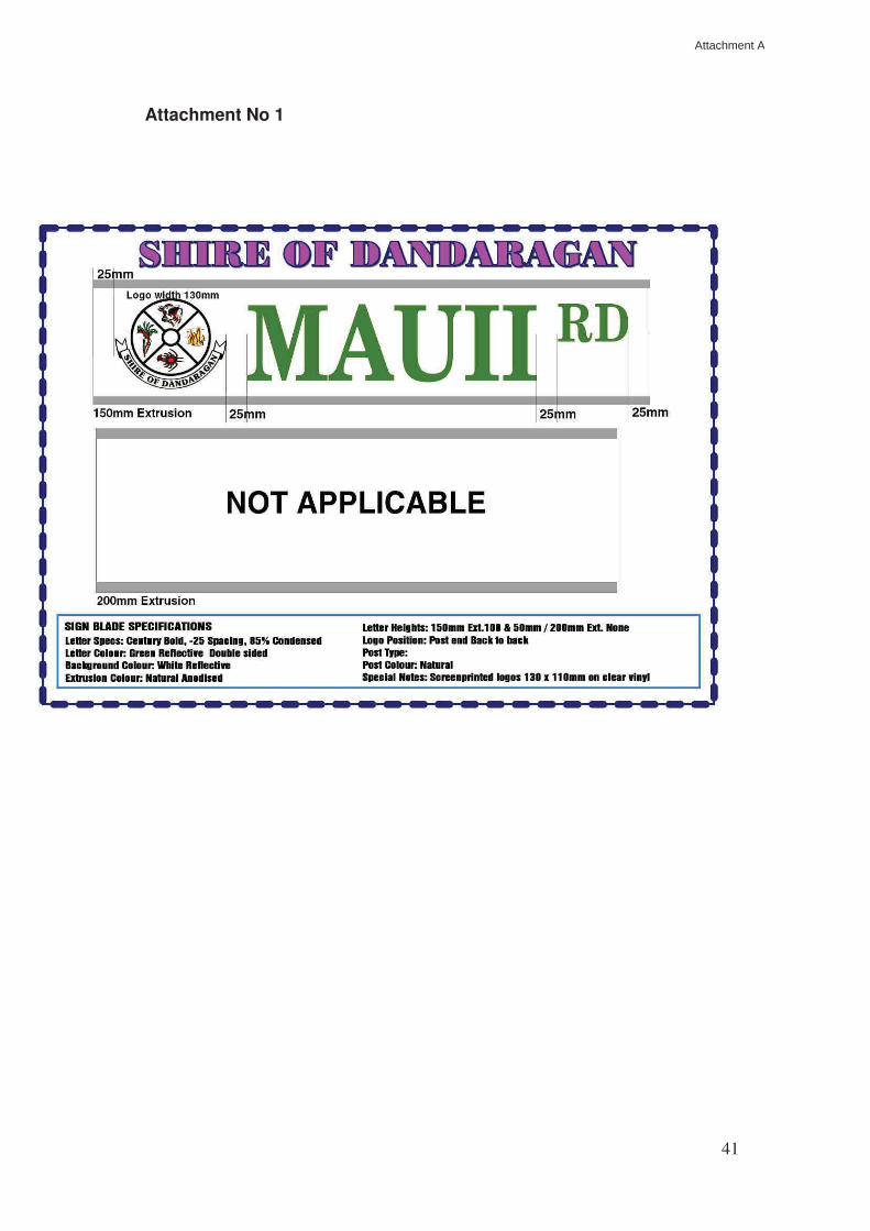
41
Attachment No 1
Attachment A
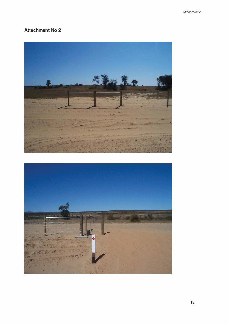
42
Attachment No 2
Attachment A
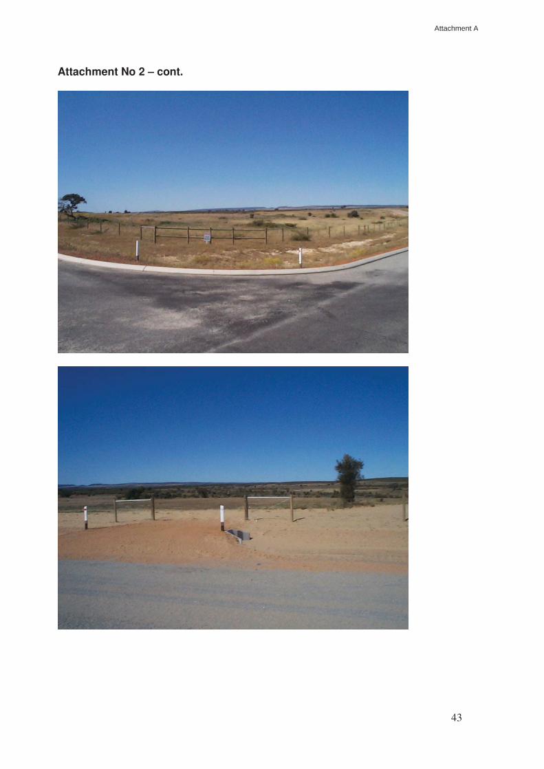
43
Attachment No 2 – cont.
Attachment A
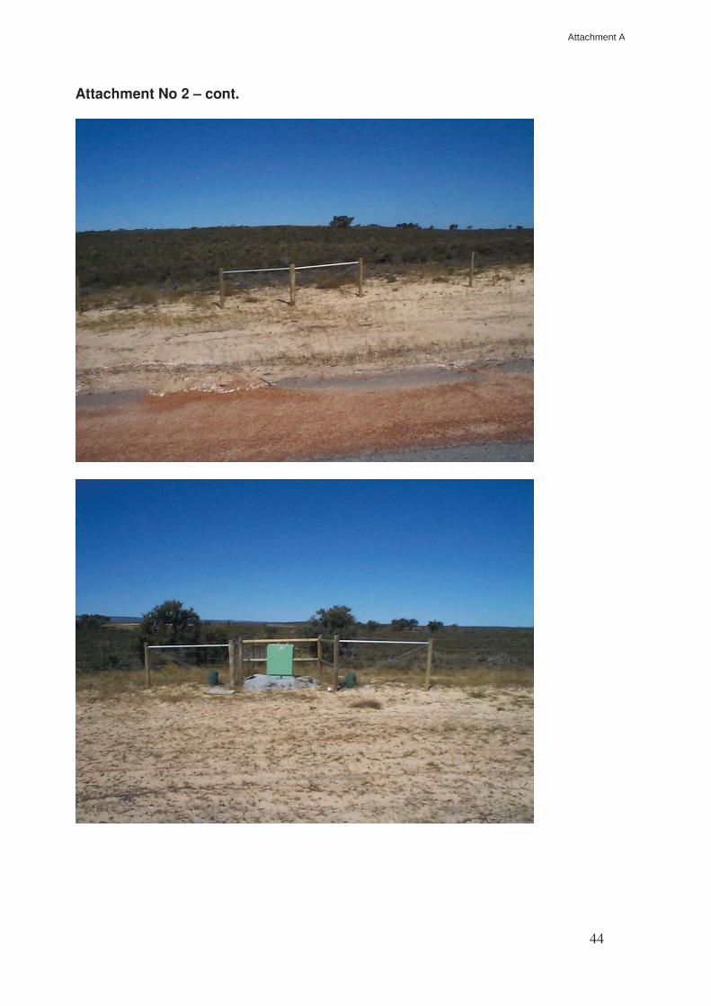
44
Attachment No 2 – cont.
Attachment A
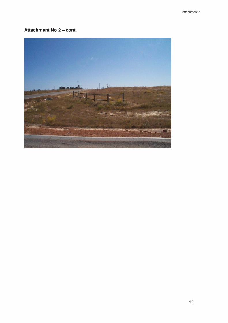
45
Attachment No 2 – cont.
Attachment A
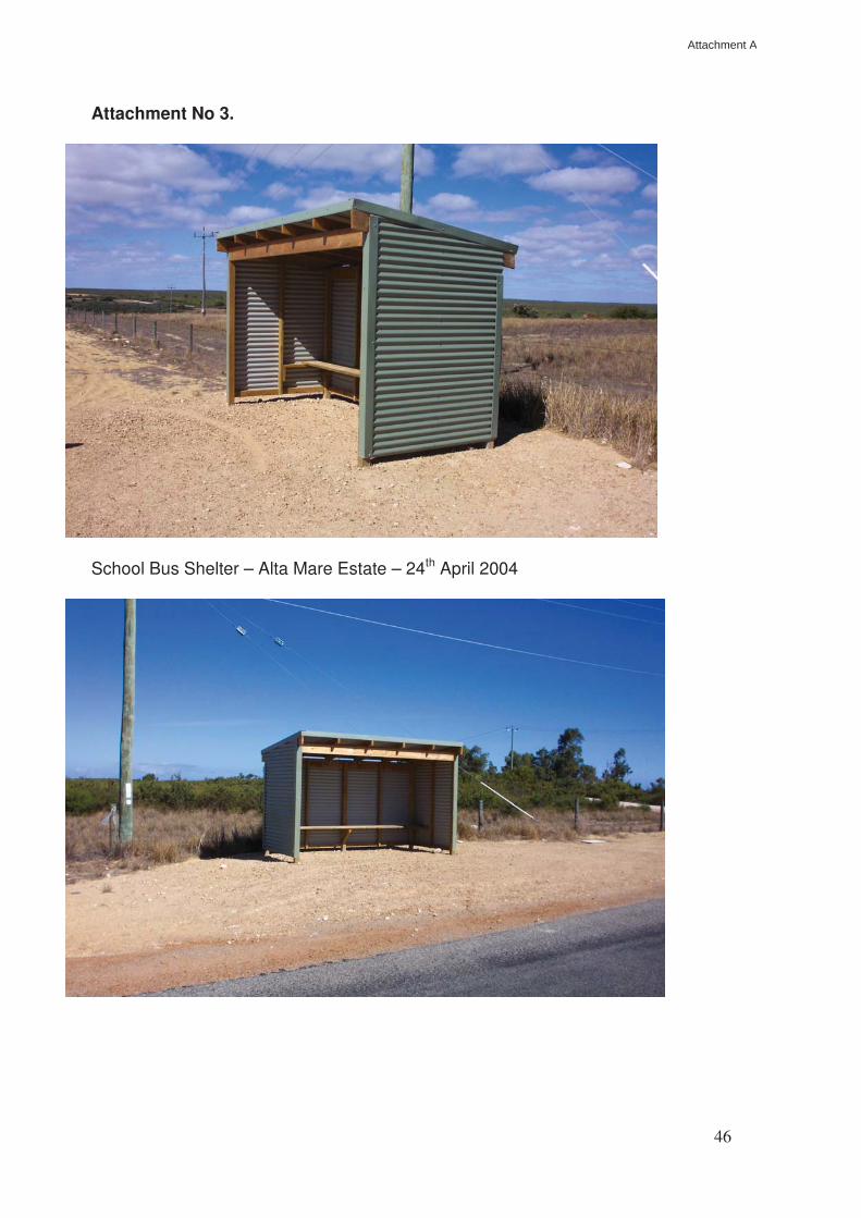
46
Attachment No 3.
School Bus Shelter – Alta Mare Estate – 24th April 2004
Attachment A
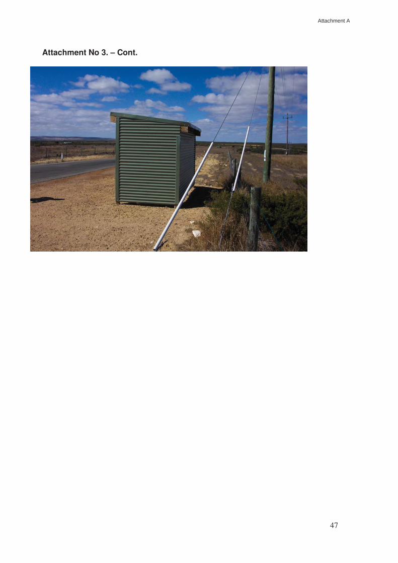
47
Attachment No 3. – Cont.
Attachment A
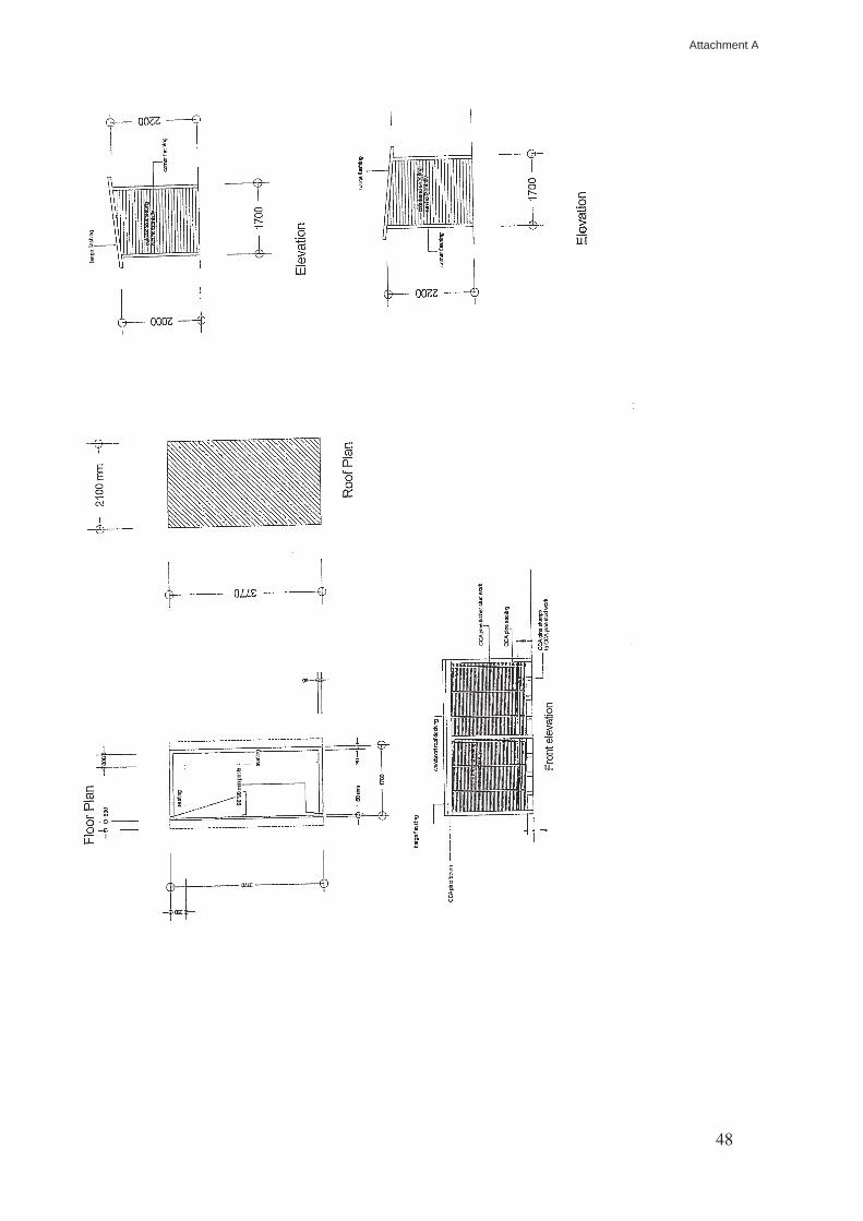
48
Attachment A
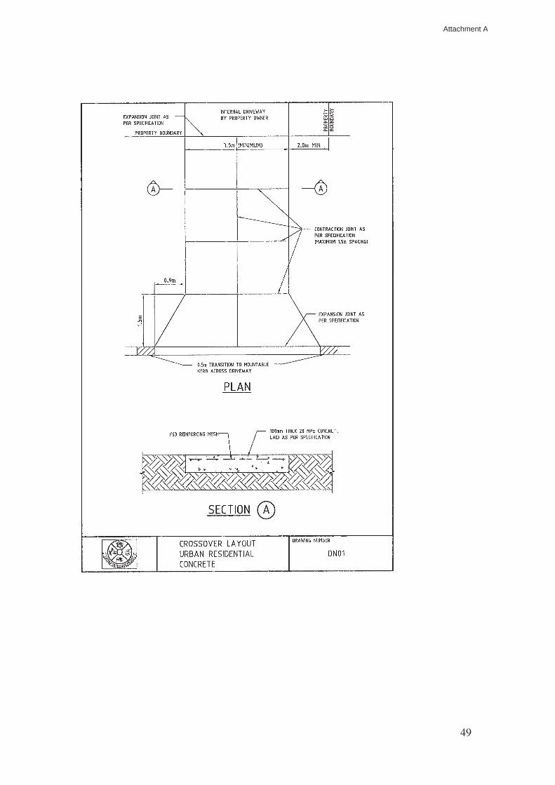
49
Attachment A

50
Attachment A
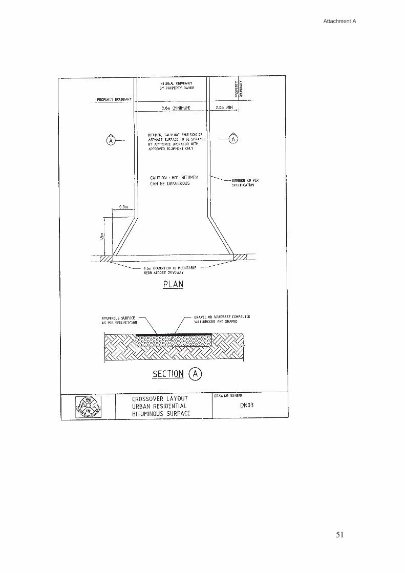
51
Attachment A
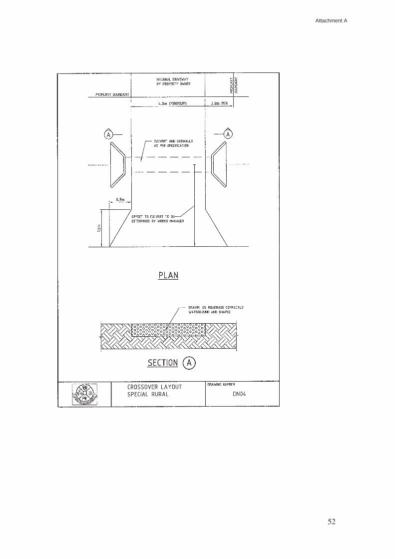
52
Attachment A
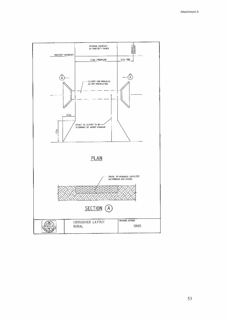
53
Attachment A
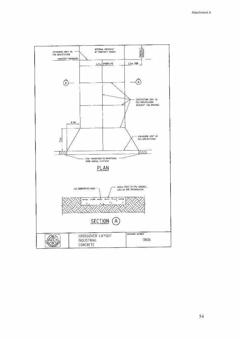
54
Attachment A
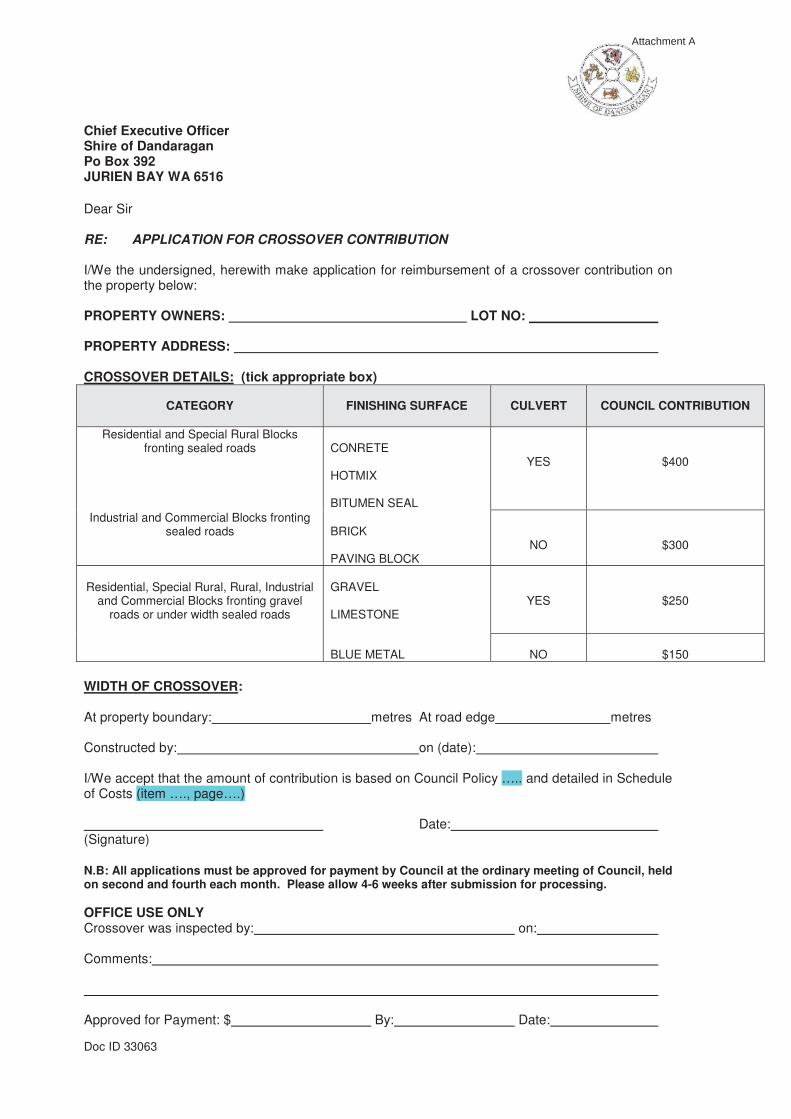
Doc ID 33063
Chief Executive Officer Shire of Dandaragan Po Box 392 JURIEN BAY WA 6516 Dear Sir RE: APPLICATION FOR CROSSOVER CONTRIBUTION I/We the undersigned, herewith make application for reimbursement of a crossover contribution on the property below: PROPERTY OWNERS: LOT NO: PROPERTY ADDRESS: CROSSOVER DETAILS: (tick appropriate box)
CATEGORY
FINISHING SURFACE
CULVERT
COUNCIL CONTRIBUTION
Residential and Special Rural Blocks fronting sealed roads
CONRETE HOTMIX BITUMEN SEAL
YES
$400
Industrial and Commercial Blocks fronting sealed roads
BRICK PAVING BLOCK
NO
$300
Residential, Special Rural, Rural, Industrial
and Commercial Blocks fronting gravel roads or under width sealed roads
GRAVEL LIMESTONE
YES
$250
BLUE METAL
NO
$150
WIDTH OF CROSSOVER: At property boundary: metres At road edge metres Constructed by: on (date): I/We accept that the amount of contribution is based on Council Policy ….. and detailed in Schedule of Costs (item …., page….) Date: (Signature) N.B: All applications must be approved for payment by Council at the ordinary meeting of Council, held on second and fourth each month. Please allow 4-6 weeks after submission for processing. OFFICE USE ONLY Crossover was inspected by: on: Comments: Approved for Payment: $ By: Date:
Attachment A