guidelines for pss-os design - iterstatic.iter.org/codac/pcdh7/folder...
TRANSCRIPT
PDF generated on 24 Jan 2016DISCLAIMER : UNCONTROLLED WHEN PRINTED – PLEASE CHECK THE STATUS OF THE DOCUMENT IN IDM
Memorandum / Note
Guidelines for PSS-OS design
This document provides the guidelines to be followed by the plant system I&C designers for the development of the part the Plant System I&C which implements the occupational safety protection functions and interfacing with the Central SafetySystems for Occupational Safety (CSS-OS).
Approval Process Name Action AffiliationAuthor Petitpas P. 08 Jan 2016:signed IO/DG/COO/SCOD/CSD/PCICo-Authors Pernin J.- M. 08 Jan 2016:signed IO/DG/COO/SCOD/CSD/PCIReviewers Fernandez Robles C.
Fourneron J.- M.08 Jan 2016:recommended11 Jan 2016:recommended
IO/DG/COO/SCOD/CSD/PCIIO/DG/COO/SCOD/CSD/PCI
Approver Delong J. 24 Jan 2016:approved IO/DG/COO/SCOD/CSD/PCIDocument Security: Internal Use
RO: Petitpas PierreRead Access LG: PBS48 team, AD: ITER, AD: External Collaborators, AD: IO_Director-General, AD: EMAB, AD: OBS -
CODAC Section (CDC), AD: OBS - Plant Control and Instrumentation Section (PCI), AD: Auditors, AD: ITER Management Assessor, project administrator, RO, AD: OBS - Control System Division (CSD) - EXT, AD:...
IDM UID
C99J7GVERSION CREATED ON / VERSION / STATUS
08 Jan 2016 / 1.6 / Approved
EXTERNAL REFERENCE / VERSION
PDF generated on 24 Jan 2016DISCLAIMER : UNCONTROLLED WHEN PRINTED – PLEASE CHECK THE STATUS OF THE DOCUMENT IN IDM
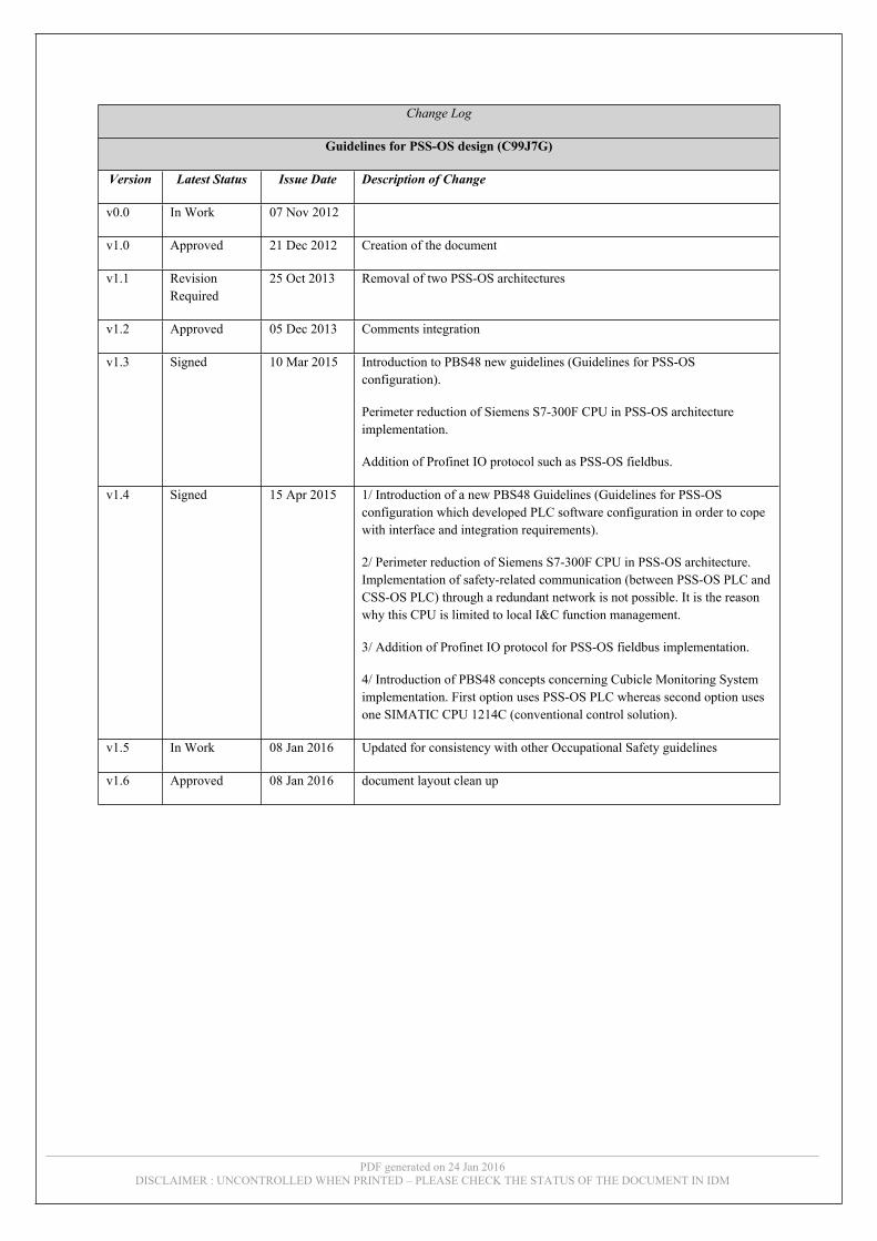
Change Log
Guidelines for PSS-OS design (C99J7G)
Version Latest Status Issue Date Description of Change
v0.0 In Work 07 Nov 2012
v1.0 Approved 21 Dec 2012 Creation of the document
v1.1 Revision Required
25 Oct 2013 Removal of two PSS-OS architectures
v1.2 Approved 05 Dec 2013 Comments integration
v1.3 Signed 10 Mar 2015 Introduction to PBS48 new guidelines (Guidelines for PSS-OS configuration).
Perimeter reduction of Siemens S7-300F CPU in PSS-OS architecture implementation.
Addition of Profinet IO protocol such as PSS-OS fieldbus.
v1.4 Signed 15 Apr 2015 1/ Introduction of a new PBS48 Guidelines (Guidelines for PSS-OS configuration which developed PLC software configuration in order to cope with interface and integration requirements).
2/ Perimeter reduction of Siemens S7-300F CPU in PSS-OS architecture. Implementation of safety-related communication (between PSS-OS PLC and CSS-OS PLC) through a redundant network is not possible. It is the reason why this CPU is limited to local I&C function management.
3/ Addition of Profinet IO protocol for PSS-OS fieldbus implementation.
4/ Introduction of PBS48 concepts concerning Cubicle Monitoring System implementation. First option uses PSS-OS PLC whereas second option uses one SIMATIC CPU 1214C (conventional control solution).
v1.5 In Work 08 Jan 2016 Updated for consistency with other Occupational Safety guidelines
v1.6 Approved 08 Jan 2016 document layout clean up

Page 1 of 58
Table of Contents
1 INTRODUCTION...............................................................................................................41.1 SCOPE ................................................................................................................................51.2 ACRONYMS ........................................................................................................................51.3 REFERENCES ......................................................................................................................7
1.3.1 Applicable documents ...............................................................................................71.3.2 Applicable standards ................................................................................................71.3.3 Reference documents.................................................................................................71.3.4 Hardware Reference documents ...............................................................................71.3.5 Software Reference documents .................................................................................7
1.4 PCDH CONTEXT ................................................................................................................82 PRINCIPLES ......................................................................................................................9
2.1 PBS48 OS GUIDELINES DOCUMENTS .................................................................................92.2 TERMINOLOGY ...................................................................................................................9
2.2.1 SCS-OS......................................................................................................................92.2.2 Safety Function .......................................................................................................102.2.3 Occupational Safety I&C Function.........................................................................102.2.4 PSS-OS....................................................................................................................102.2.5 CSS-OS....................................................................................................................112.2.6 PSN-OS ...................................................................................................................112.2.7 CSN-OS ...................................................................................................................122.2.8 Occupational Safety Event ......................................................................................122.2.9 Occupational Safety Action.....................................................................................122.2.10 Non-critical supervision system..............................................................................122.2.11 Critical supervision system .....................................................................................13
2.3 OS FUNCTION SCOPE ........................................................................................................132.3.1 Local OS function – Automatic activation ..............................................................132.3.2 Central OS function – Automatic activation ...........................................................142.3.3 Central OS function – Manual activation ...............................................................15
3 SCS-OS INTRODUCTION..............................................................................................173.1 OS HMIS .........................................................................................................................17
3.1.1 CSS-OS Operational Components ..........................................................................183.1.1.1 Safety Critical Hardwired HMI.......................................................................183.1.1.2 OS SCADA.....................................................................................................18
3.1.2 CSS-OS Maintenance Components.........................................................................193.1.2.1 CSS-OS Maintenance Terminals ....................................................................193.1.2.2 CSS-OS Engineering workstation...................................................................19
4 PSS-OS ARCHITECTURES ...........................................................................................20

Page 2 of 58
4.1 PSS-OS WITH CENTRALIZED I/O BASED ON S7 DISTRIBUTED SAFETY FAIL-SAFE SYSTEM ARCHITECTURE ........................................................................................................................214.2 PSS-OS WITH DISTRIBUTED I/O BASED ON S7 DISTRIBUTED SAFETY FAIL-SAFE SYSTEM ARCHITECTURE ........................................................................................................................224.3 PSS-OS WITH DISTRIBUTED I/O BASED ON S7 F/FH FAIL-SAFE SYSTEM ARCHITECTURE 244.4 FAULT TOLERANT PSS-OS BASED ON S7 F/FH FAIL-SAFE SYSTEM ARCHITECTURE ........25
5 OS FUNCTION RESPONSE TIME ...............................................................................286 PERIODIC TESTS REQUIREMENTS .........................................................................307 SENSORS AND ACTUATORS.......................................................................................31
7.1 SIMATIC F-MODULES REQUIREMENTS ...........................................................................317.2 IEC STANDARDS CONCEPTS .............................................................................................31
7.2.1 Fail-safe concept.....................................................................................................317.2.1.1 Definition ........................................................................................................317.2.1.2 Principles.........................................................................................................317.2.1.3 Energized to trip & de-energized to trip concepts ..........................................327.2.1.4 Signal monitoring............................................................................................327.2.1.5 Conclusion ......................................................................................................33
7.2.2 Proven in use concept .............................................................................................347.2.3 Diversity concept.....................................................................................................34
8 NETWORKS AND COMMUNICATIONS ...................................................................358.1 CONNECTION BETWEEN PSS-OS AND CSS-OS................................................................35
8.1.1 Interface with the CSS-OS Safety PLC ...................................................................368.1.2 Interface with the CSS-OS SCADA servers.............................................................368.1.3 Interface with the CSS-OS Engineering Workstation .............................................368.1.4 Interface with the CSS-OS NTP server ...................................................................36
8.2 CONNECTION BETWEEN PSS-OS AND THE I/O MODULES .................................................368.2.1 Profibus DP case ....................................................................................................378.2.2 Profinet IO case ......................................................................................................38
9 HARDWARE ....................................................................................................................419.1 PSS-OS PLC ...................................................................................................................41
9.1.1 Limited scope of CPU 300F PN/DP .......................................................................419.1.2 SIMATIC S7 Fail-safe Systems comparison ...........................................................42
9.2 PSS-OS CUBICLES ...........................................................................................................429.2.1 Environmental conditions .......................................................................................439.2.2 Cubicle Monitoring .................................................................................................43
9.3 PSS-OS SWITCH ..............................................................................................................449.4 PSS-OS SIGNAL CABLING ................................................................................................459.5 PSS-OS POWERING ..........................................................................................................45
9.5.1 Conceptual principles .............................................................................................459.5.2 CPU racks of PSS-OS architectures based on S7 Distributed Safety.....................469.5.3 CPU racks of PSS-OS architecture based on S7 F/FH System ..............................47

Page 3 of 58
9.5.4 Peripheral racks......................................................................................................489.5.5 Network products ....................................................................................................489.5.6 CPU1214C Controller ............................................................................................489.5.7 Monitoring ..............................................................................................................49
9.6 CUBICLE INSTRUMENTATION ...........................................................................................499.6.1 Procurement and Integration..................................................................................49
10 SOFTWARE TOOLS.......................................................................................................5011 SOFTWARE INTERFACES WITH THE CSS-OS ......................................................51
11.1 INTERFACE WITH THE CSS-OS SAFETY PLC....................................................................5111.1.1 Functional concepts ................................................................................................5111.1.2 Method ....................................................................................................................51
11.2 INTERFACE WITH THE CSS-OS SCADA SERVERS............................................................5211.2.1 Functional concepts ................................................................................................5211.2.2 Method ....................................................................................................................52
11.3 INTERFACE WITH THE CSS-OS NTP SERVERS..................................................................5311.4 INTERFACE WITH THE CSS-OS ENGINEERING WORKSTATION .........................................53
12 TESTING AND ACCEPTANCE TESTS.......................................................................5412.1 FAT .................................................................................................................................5412.2 SAT .................................................................................................................................55
13 STANDARDS COMPLIANCE AND SIL ASSESSMENT...........................................56

Page 4 of 58
1 Introduction
Occupational safety (OS) is a cross-disciplinary area concerned with protecting the safety, health and welfare of people engaged in work or employment. The goal of all occupational safety and health programs is to foster a safe work environment.In the ITER project, safety concerns are divided into:
• Nuclear safety risks related to internal and external exposure to ionizing radiation and releases of radioactive material,
• Occupational safety risks, covering all non-nuclear risks.
Occupational safety risks include, among others: • Work in confined spaces,• Proximity to heavy duty equipment,• Elevated loads,• Pressure build-up in circuits,• High temperature,• Cryogenic risks,• Electrical risks,• Magnetic risks,• Oxygen depletion.
Two types of protection can be implemented for preventing and/or mitigating OS risks: Physical protections implemented within system design. These are inherent protections embedded in the
component, assembly or system itself and which do not involve I&C Systems (e.g. passive safety relief valves, cages, locking system....),
I&C protections, which are instrumented functions which protect and warn personnel against possible immediate risks due to machine or systems failure, malfunctioning or normal hazardous operation (e.g. oxygen monitoring, leak detection……).
The Safety Control System for Occupational Safety (SCS-OS) provides an I&C safety system for the entire ITER plant for the protection of people and the environment, covering occupational safety issues related to non-nuclear risks. Like other ITER Control Systems, this system is based on two layers architecture with the Central Safety System for Occupational Safety (CSS-OS) at central level and the Plant Safety Systems for Occupational Safety (PSS-OS) at plant level.Caution: The SCS-OS does not house all I&C protections which participate to OS risks prevention and mitigation.The following elements are not included in the safety I&C system for occupational safety:
• Fire detection and protection systems, as these are independent systems delivered by PBS.62 and 63 (Buildings),
• Radiation protection system, as it is an independent system delivered by PBS.64 (Radiological and Environmental Monitoring),
• Access control system, which provides access to controlled zones where it is necessary to control on site movement and to ensure that only properly authorized people have access, as it is an independent system delivered by PBS.69 (Access Control and Security Systems),
• European Machinery Directive safety functions which shall cope with ISO 13849-1 or IEC 62061 Safety standards (e.g. enclosure interlock or emergency stop button),
• Safety functions using Emergency Electrical Power cut-off button (installed in front doors of electrical boards for example). Refer to [RD10] – Emergency devices for OHS risks [ITER_D_6LFNJT] for more details about related safety functions,
• I&C functions that have no specific Safety Integrity Level (SIL according to IEC 61508 / IEC 61511) requirements, as these systems can be implemented with conventional I&C,

Page 5 of 58
• Nuclear Safety Control System,• Interlock Control System, which is devoted to investment protection.
The figure below presents the layers of protection for Occupational Safety risks management. The SCS-OS and associated OS I&C functions operate for prevention and mitigation purpose at two levels:
Critical alarms and operating procedures, Automatic I&C functions.
PROCESS
CONVENTIONAL CONTROL & MONITORING
CRITICAL ALARMS AND OPERATING PROCEDURES
AUTOMATIC I&C FUNCTIONS
PHYSICAL PROTECTION & MITIGATION SYSTEMS
EMERGENCY RESPONSE
INCIDENT
Prevention
Mitigation
CODAC I&C functions
Fire detection and protection functions
Collecting basin
Discharge means
SCS-OS I&C functions
Machinery Directive safety I&C functions
Machinery Directive safety I&C functions
Figure 1-1: Layer of Protection for OS risks management
1.1 Scope This document provides the guidelines to be followed by the plant system I&C designers for the design of the Plant Safety System for Occupational Safety (PSS-OS) which implements the occupational safety protection functions and interfaces with the Central Safety Systems for Occupational Safety (CSS-OS).
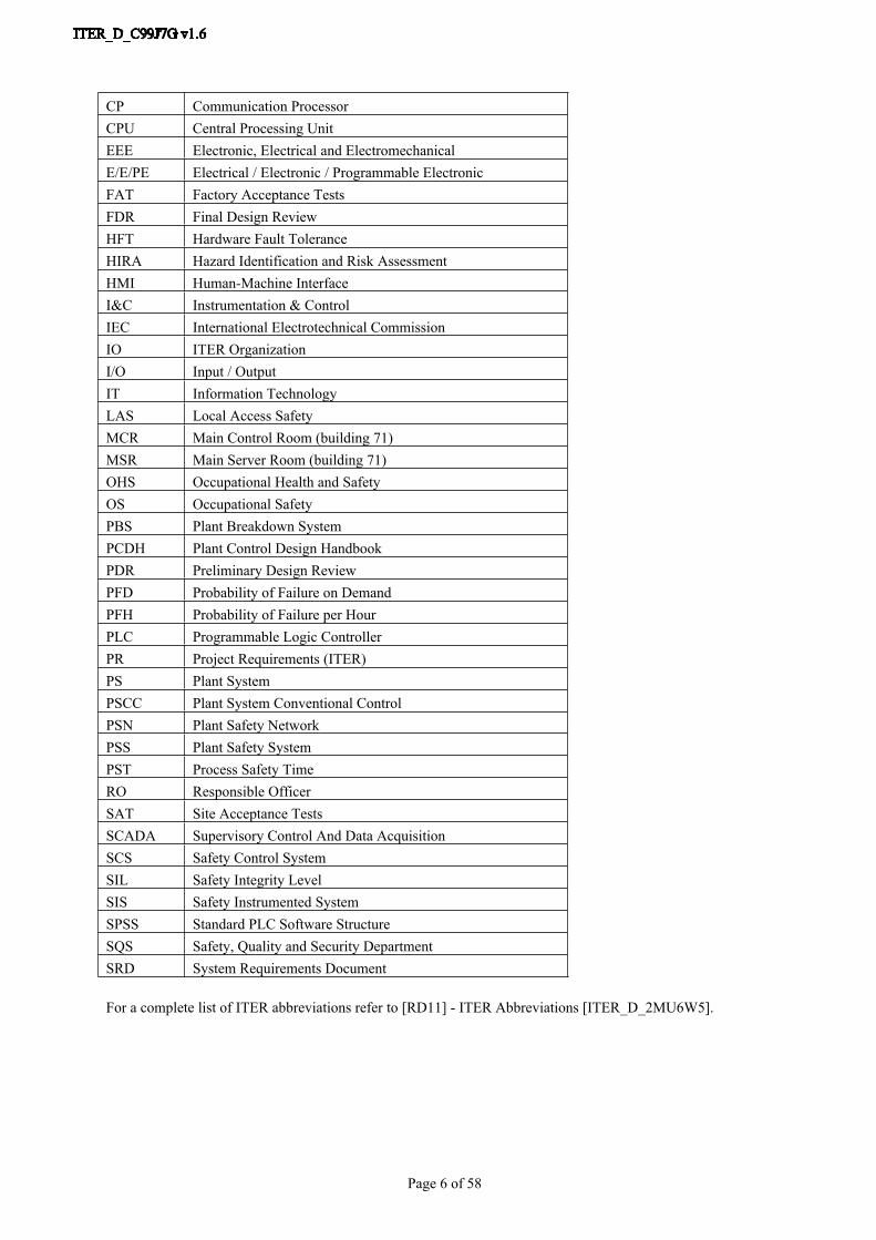
1.2 AcronymsAcronym Item
BCR Backup Control Room (building 24)BSR Backup Server Room (building 24)CDR Conceptual Design reviewCFC Continuous Function ChartsCIS Central Interlock SystemCNP Central I&C Network PanelCSN Central Safety NetworkCSS Central Safety SystemCODAC Control, Data Access and Communication
Page 6 of 58
For a complete list of ITER abbreviations refer to [RD11] - ITER Abbreviations [ITER_D_2MU6W5].
CP Communication ProcessorCPU Central Processing UnitEEE Electronic, Electrical and ElectromechanicalE/E/PE Electrical / Electronic / Programmable ElectronicFAT Factory Acceptance TestsFDR Final Design ReviewHFT Hardware Fault ToleranceHIRA Hazard Identification and Risk AssessmentHMI Human-Machine InterfaceI&C Instrumentation & ControlIEC International Electrotechnical CommissionIO ITER OrganizationI/O Input / OutputIT Information TechnologyLAS Local Access SafetyMCR Main Control Room (building 71)MSR Main Server Room (building 71)OHS Occupational Health and SafetyOS Occupational SafetyPBS Plant Breakdown SystemPCDH Plant Control Design HandbookPDR Preliminary Design ReviewPFD Probability of Failure on DemandPFH Probability of Failure per HourPLC Programmable Logic ControllerPR Project Requirements (ITER)PS Plant SystemPSCC Plant System Conventional ControlPSN Plant Safety NetworkPSS Plant Safety SystemPST Process Safety TimeRO Responsible OfficerSAT Site Acceptance TestsSCADA Supervisory Control And Data AcquisitionSCS Safety Control SystemSIL Safety Integrity LevelSIS Safety Instrumented SystemSPSS Standard PLC Software StructureSQS Safety, Quality and Security DepartmentSRD System Requirements Document
Page 7 of 58
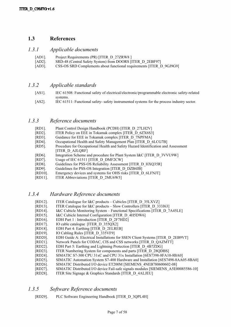
1.3 References
1.3.1 Applicable documents[AD1]. Project Requirements (PR) [ITER_D_27ZRW8 ][AD2]. SRD-48 (Central Safety System) from DOORS [ITER_D_2EBF97][AD3]. CSS-OS SRD Complements about functional requirements [ITER_D_9GJ9G9]
1.3.2 Applicable standards[AS1]. IEC 61508: Functional safety of electrical/electronic/programmable electronic safety-related
systems.[AS2]. IEC 61511: Functional safety- safety instrumented systems for the process industry sector.
1.3.3 Reference documents[RD1]. Plant Control Design Handbook (PCDH) [ITER_D_27LH2V][RD2]. ITER Policy on EEE in Tokamak complex [ITER_D_6ZX6S3][RD3]. Guidance for EEE in Tokamak complex [ITER_D_7NPFMA][RD4]. Occupational Health and Safety Management Plan [ITER_D_6LCG7B][RD5]. Procedure for Occupational Health and Safety Hazard Identification and Assessment
[ITER_D_AJLQRF][RD6]. Integration Scheme and procedure for Plant System I&C [ITER_D_3VVU9W][RD7]. Usage of IEC 61511 [ITER_D_DMF2CW][RD8]. Guidelines for PSS-OS Reliability Assessment [ITER_D_HXQ35R][RD9]. Guidelines for PSS-OS Integration [ITER_D_DZB4JB][RD10]. Emergency devices and systems for OHS risks [ITER_D_6LFNJT][RD11]. ITER Abbreviations [ITER_D_2MU6W5]
1.3.4 Hardware Reference documents[RD12]. ITER Catalogue for I&C products – Cubicles [ITER_D_35LXVZ][RD13]. ITER Catalogue for I&C products – Slow Controllers [ITER_D_333J63][RD14]. I&C Cubicle Monitoring System – Functional Specifications [ITER_D_7A45LE][RD15]. I&C Cubicle Internal Configuration [ITER_D_4H5DW6][RD16]. EDH Part 1 : Introduction [ITER_D_2F7HD2][RD17]. IO cable catalogue [ITER_D_355QX2][RD18]. EDH Part 4: Earthing [ITER_D_2ELREB][RD19]. IO Cabling Rules [ITER_D_335VF9][RD20]. EDH Guide A: Electrical Installations for SSEN Client Systems [ITER_D_2EB9VT][RD21]. Network Panels for CODAC, CIS and CSS networks [ITER_D_QAZMTT][RD22]. EDH Part 5: Earthing and Lightning Protection [ITER_D_4B7ZDG][RD23]. ITER Numbering System for components and parts [ITER_D_28QDBS][RD24]. SIMATIC S7-300 CPU 31xC and CPU 31x Installation [6ES7398-8FA10-8BA0][RD25]. SIMATIC Automation System S7-400 Hardware and Installation [6ES7498-8AA05-8BA0][RD26]. SIMATIC Distributed I/O device ET200M [SIEMENS_4NEB780600602-08][RD27]. SIMATIC Distributed I/O device Fail-safe signals modules [SIEMENS_A5E00085586-10][RD28]. ITER Site Signage & Graphics Standards [ITER_D_4ALJEU]
1.3.5 Software Reference documents[RD29]. PLC Software Engineering Handbook [ITER_D_3QPL4H]

Page 8 of 58
[RD30]. Philosophy of ITER Alarm System Management [ITER_D_3WCD7T][RD31]. SIEMENS S7 Safety Engineering System Manual [SIEMENS_A5E00109529-06][RD32]. Guidelines for PSS-OS Configuration [ITER_D_Q6KVXS][RD33]. Occupational Safety Cubicle Monitoring System based on S7-1200 [ITER_D_DZJ4ZT]
1.4 PCDH contextThe [RD1] - Plant Control Design Handbook (PCDH), defines methodology, standards, specifications and interfaces applicable to the whole life cycle of ITER plant systems Instrumentation & Control (I&C) Systems. I&C standards are essential for ITER to:
• Integrate all plant systems into one integrated control system,• Maintain all plant systems after delivery acceptance,• Contain cost by economy of scale.
PCDH comprises a core document which presents the plant system I&C life cycle and recaps the main rules to be applied to the plant system I&Cs for conventional controls, interlocks and safety controls. Some I&C topics are explained in greater detail in dedicated documents associated with PCDH [RD1]. This document is one of them.
Core PCDH (27LH2V)Plant system control philosophyPlant system control Life CyclePlant system control specificationsCODAC interface specificationsInterlock I&C specificationSafety I&C specification
PCDH core and satellite documents: v7PS CONTROL DESIGN
Plant system I&C architecture (32GEBH)
Methodology for PS I&C specifications (353AZY)
CODAC Core System Overview (34SDZ5) INTERLOCK CONTROLS
Guidelines PIS design (3PZ2D2)
Guidelines for PIS integration & config. (7LELG4)
Management of local interlock functions (75ZVTY)
PIS Operation and Maintenance (7L9QXR)
I&C CONVENTIONSI&C Signal and variable naming (2UT8SH)
ITER CODAC Glossary (34QECT)
ITER CODAC Acronym list (2LT73V)
PS SELF DESCRIPTION DATASelf description schema documentation (34QXCP)
CATALOGUES for PS CONTROLSlow controllers products (333J63)
Fast controller products (345X28)
Cubicle products (35LXVZ)
Integration kit for PS I&C (C8X9AE)
PS CONTROL INTEGRATIONThe CODAC -PS Interface (34V362)
PS I&C integration plan (3VVU9W) ITER alarm system management (3WCD7T)
ITER operator user interface (3XLESZ)
Guidelines for PON archiving (87N2B7)
PS Operating State management (AC2P4J)
Guidelines for Diagnostic data structure (354SJ3)PS CONTROL DEVELOPMENT
I&C signal interface (3299VT)
PLC software engineering handbook (3QPL4H)
Guidelines for fast controllers (333K4C)
CODAC software development environment (2NRS2K)
Guidelines for I&C cubicle configurations (4H5DW6)
CWS case study specifications (35W299)
NUCLEAR PCDH (2YNEFU)
OCCUPATIONAL SAFETY CONTROLSGuidelines for PSS design
Available and approvedExpected
Legend
This document
(XXXXXX) IDM ref.
Guidelines for PSS-OS Design (C99J7G)
Figure 1-2: PCDH documents structure

Page 9 of 58
2 Principles
2.1 PBS48 OS Guidelines documentsThe SCS-OS safety I&C functions have to fulfil the requirements of the IEC 61508 [AS1] and the IEC 61511 [AS2] Functional Safety standards throughout the safety life cycle. The SCS-OS must also be a homogeneous and efficient overall I&C system. These are the reasons why PBS48 OS proposes several guidelines to the Plant Systems to provide them a maximum of input for implementation & integration purpose.
The present document provides the guidelines to be followed by the plant system I&C designers for the hardware implementation of the part of the Plant System I&C which implements the occupational safety I&C functions and interfaces with the Central Safety Systems for Occupational Safety (CSS-OS). In parallel, PBS48 OS supplies others guidelines documents:
Guidelines for PSS-OS Reliability Assessment which introduces IEC Safety functional standards requirements to be scrupulously taking into account by each Plant System in order to obtain targeted SIL certification. This document presents also an analysis of the equipment integrity level involved in the implementation of OS I&C functions through the study of the various PSS-OS architectures proposed by PBS48 OS.
Guidelines for PSS-OS Configuration which develops PLC software configuration to be taking into account by each Plant System in order to cope with interface and integration requirements. This documents studies SIMATIC project & software structure, functional concepts & methodology for the interfaces with the CSS-OS through attached PLC application and various recommendations.
Guidelines for PSS-OS Integration which provides details and procedures for the integration phase of the PSS-OS into the SCS-OS.
Refer to [RD8] - Guidelines for PSS-OS Reliability Assessment [ITER_D_HXQ35R], [RD32] - Guidelines for PSS-OS Configuration [ITER_D_Q6KVXS] and [RD9] – Guidelines for PSS-OS Integration [ITER_D_DZB4JB] for more details.
2.2 Terminology
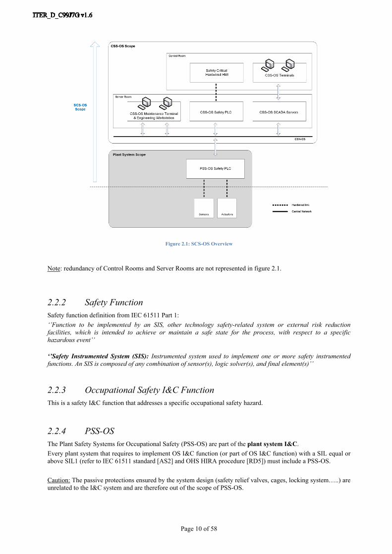
2.2.1 SCS-OSThe Safety Control System for Occupational Safety (SCS-OS) is in charge of the supervision and control of the ITER components involved in the safety instrumented functions which protect people and environment regarding occupational safety issues related to non-nuclear risks.It comprises the Central Safety System for Occupational Safety (CSS-OS), the different Plant Safety Systems for Occupational Safety (PSS-OS) and its networks (CSN-OS and PSN-OS).
Note: The SCS-OS does not include the sensors and actuators of the Plant Systems but controls them through the PSS-OS.
Page 10 of 58
Figure 2.1: SCS-OS Overview
Note: redundancy of Control Rooms and Server Rooms are not represented in figure 2.1.
2.2.2 Safety FunctionSafety function definition from IEC 61511 Part 1: ‘’Function to be implemented by an SIS, other technology safety-related system or external risk reduction facilities, which is intended to achieve or maintain a safe state for the process, with respect to a specific hazardous event’’
‘’Safety Instrumented System (SIS): Instrumented system used to implement one or more safety instrumented functions. An SIS is composed of any combination of sensor(s), logic solver(s), and final element(s)’’
2.2.3 Occupational Safety I&C FunctionThis is a safety I&C function that addresses a specific occupational safety hazard.
2.2.4 PSS-OSThe Plant Safety Systems for Occupational Safety (PSS-OS) are part of the plant system I&C. Every plant system that requires to implement OS I&C function (or part of OS I&C function) with a SIL equal or above SIL1 (refer to IEC 61511 standard [AS2] and OHS HIRA procedure [RD5]) must include a PSS-OS. Caution: The passive protections ensured by the system design (safety relief valves, cages, locking system…..) are unrelated to the I&C system and are therefore out of the scope of PSS-OS.

Page 11 of 58
Each PSS-OS provides local I&C protections by implementing the local occupational safety I&C functions of the corresponding plant system and may also participates in the central occupational safety I&C functions coordinated by the CSS-OS.
The PSS-OS does not include the sensors and actuators of the plant system involved in the OS I&C functions.The PSS-OS is independent (in terms of hardware components & associated software) of the I&C system that manages the nuclear safety I&C functions of the plant system (PSS-N).The PSS-OS is also independent (in terms of hardware components & associated software) of the conventional control I&C systems of the Plant System (PSCC) and of the I&C system that manage the investment protection (Interlock) functions (PIS) of the Plant System.
2.2.5 CSS-OSThe Central Safety System for Occupational Safety is the central part of the SCS-OS, which integrates functions to coordinate the locally distributed plant I&C systems. It retrieves/manages data from the distributed systems to activate protections in order to remove or reduce hazardous conditions which have been detected. It does this either automatically, or by a manual operator command from the operator’s safety desks located in the control rooms.At the central level, the Central Safety System for Occupational Safety (CSS-OS, managed by PBS.48) is responsible for providing:
- CSS-OS PLCs which host safety applications for coordinating the plant systems,- Human machine interfaces for the supervisory features of all the OS I&C functions that have to be
reported in control rooms: monitoring, control, diagnostic, maintenance and archiving,- A dedicated redundant network (CSN-OS, refer to section 2.2.7) to enable communication between all
the OS systems,- Engineering workstation,- Hardwired panels to manage central functions with manual activation and to display information that
requires a high reliability.
The CSS-OS is implanted in the server-rooms and control-rooms of buildings 71 and 24. The CSS-OS is beyond the scope of this document.The CSS-OS is independent from the system that manages nuclear safety functions.
Notes: - PBS.48 (CSS) also implements central systems for nuclear safety. The design of this system is detailed in
a dedicated document.- The Central Safety Systems together with CODAC and the Central Interlock System (CIS) form the
ITER I&C Central Systems.
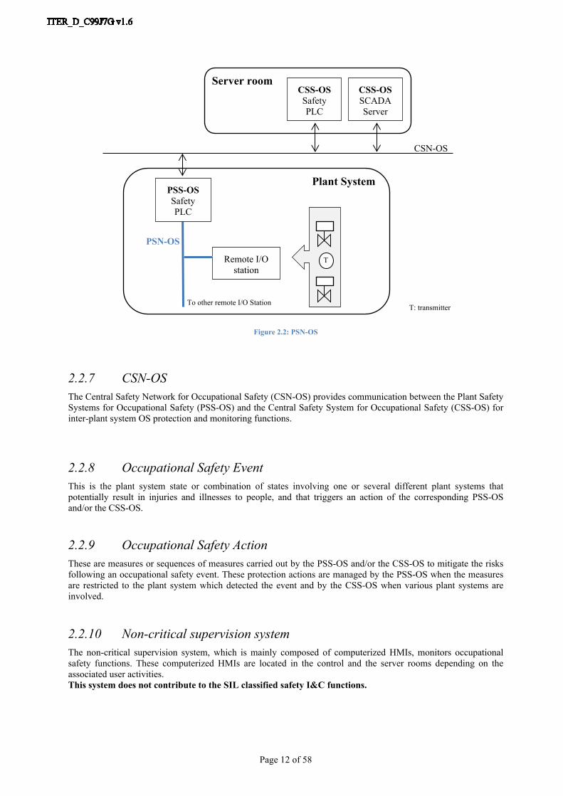
2.2.6 PSN-OSThe Plant Safety Network for Occupational Safety (PSN-OS) provides communication between the components involved in the OS I&C functions inside one plant system. The PSN-OS connects the PSS-OS PLC in a plant system to the sensors and actuators involved in OS I&C functions in the same plant system when distributed I/O stations are used.When a plant system includes several PSS-OS PLC, the PSN-OS also connects them together.The PSN-OS of one plant system will not be shared with other plant systems.
Page 12 of 58
Server room
Plant System
CSN-OS
PSN-OS
Remote I/O station
CSS-OS Safety PLC
T
T: transmitter
PSS-OS Safety PLC
To other remote I/O Station
CSS-OS SCADA Server
Figure 2.2: PSN-OS
2.2.7 CSN-OSThe Central Safety Network for Occupational Safety (CSN-OS) provides communication between the Plant Safety Systems for Occupational Safety (PSS-OS) and the Central Safety System for Occupational Safety (CSS-OS) for inter-plant system OS protection and monitoring functions.
2.2.8 Occupational Safety EventThis is the plant system state or combination of states involving one or several different plant systems that potentially result in injuries and illnesses to people, and that triggers an action of the corresponding PSS-OS and/or the CSS-OS.
2.2.9 Occupational Safety ActionThese are measures or sequences of measures carried out by the PSS-OS and/or the CSS-OS to mitigate the risks following an occupational safety event. These protection actions are managed by the PSS-OS when the measures are restricted to the plant system which detected the event and by the CSS-OS when various plant systems are involved.
2.2.10 Non-critical supervision systemThe non-critical supervision system, which is mainly composed of computerized HMIs, monitors occupational safety functions. These computerized HMIs are located in the control and the server rooms depending on the associated user activities.This system does not contribute to the SIL classified safety I&C functions.

Page 13 of 58
2.2.11 Critical supervision systemThe critical supervision system is a component of the CSS-OS which has the ability to contribute to the SIL classified occupational safety I&C functions, unlike the non-critical supervision system. Physically, this system will be implemented as two redundant hardwired panels, one in the Main Control Room for the safety operators, and the other in the Back-Up Control Room.These components monitor and also control some specific critical OS functions.
2.3 OS function scopeGiven the organizational division of ITER and in order to meet the safety requirements, the functional requirements address two different needs:
- Each plant system must have the means to detect and reduce its own OS risks locally,- If different plant systems are involved in the same OS function, a central system must coordinate the
locally distributed safety systems.
Two categories of occupational safety functions are defined:- “Automatic” type: in this case, the risk is controlled by the SCS-OS without any human intervention.
These functions are monitored from a computerized HMI, with detailed diagnostic performance (Non-critical Supervision System),
- “Requiring human intervention” type: high occupational risks that require a human response. The alarms and information related to these functions are displayed on a very reliable hardwired HMI (Critical Supervision System) because they trigger an action by the operator and consequently the safety action. These functions are also monitored from a computerized HMI, with detailed diagnostic performance (Non-critical Supervision System).
Apart from a minimal number of specific cases, the occupational risk functions are automatic functions.
From these requirements and to cover all future OS functions, PBS48 has identified three OS function types. The following sections describe these OS function types.
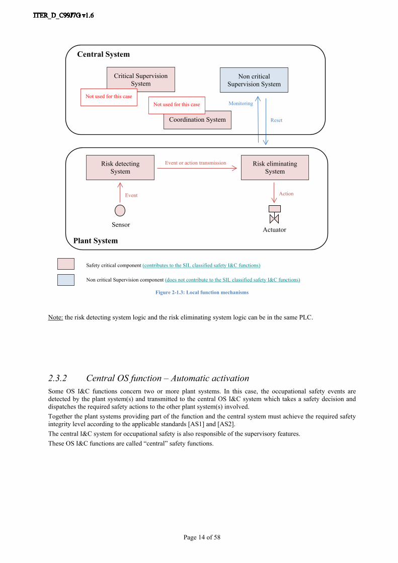
2.3.1 Local OS function – Automatic activationThe plant system has the means of detecting its OS risk (it has its own sensors) and of reducing it (its own actuators) thereby performing an automatic safety protection or mitigation action to control the risk.Therefore, throughout its life cycle the plant system is fully responsible for the safety integrity level of its own occupational safety I&C functions as defined in the applicable standards [AS1] and [AS2].The central I&C system for occupational safety does not play an active role in the safety function but it is in charge of the supervisory features related to it.These OS I&C functions are called “local” safety functions.
Page 14 of 58
Monitoring
Reset
Plant System
Event or action transmission
ActionEvent
ActuatorSensor
Critical Supervision System
Non critical Supervision System
Coordination System
Risk detecting System
Risk eliminating System
Central System
Not used for this caseNot used for this case
Safety critical component (contributes to the SIL classified safety I&C functions)
Non critical Supervision component (does not contribute to the SIL classified safety I&C functions)
Figure 2-1.3: Local function mechanisms
Note: the risk detecting system logic and the risk eliminating system logic can be in the same PLC.
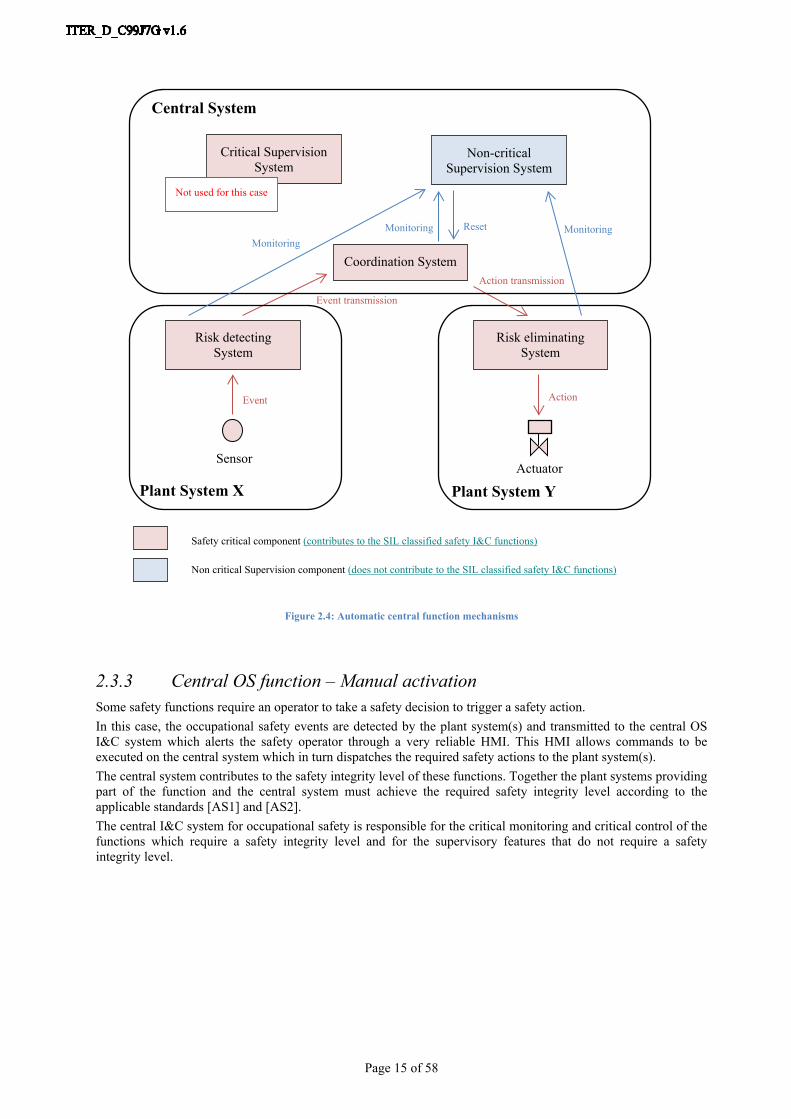
2.3.2 Central OS function – Automatic activationSome OS I&C functions concern two or more plant systems. In this case, the occupational safety events are detected by the plant system(s) and transmitted to the central OS I&C system which takes a safety decision and dispatches the required safety actions to the other plant system(s) involved.Together the plant systems providing part of the function and the central system must achieve the required safety integrity level according to the applicable standards [AS1] and [AS2].The central I&C system for occupational safety is also responsible of the supervisory features.These OS I&C functions are called “central” safety functions.
Page 15 of 58
MonitoringMonitoring
Central System
Plant System Y
Monitoring Reset
Plant System X
Event transmission
ActionEvent
ActuatorSensor
Critical Supervision System
Non-critical Supervision System
Coordination System
Risk detecting System
Risk eliminating System
Action transmission
Not used for this case
Safety critical component (contributes to the SIL classified safety I&C functions)
Non critical Supervision component (does not contribute to the SIL classified safety I&C functions)
Figure 2.4: Automatic central function mechanisms
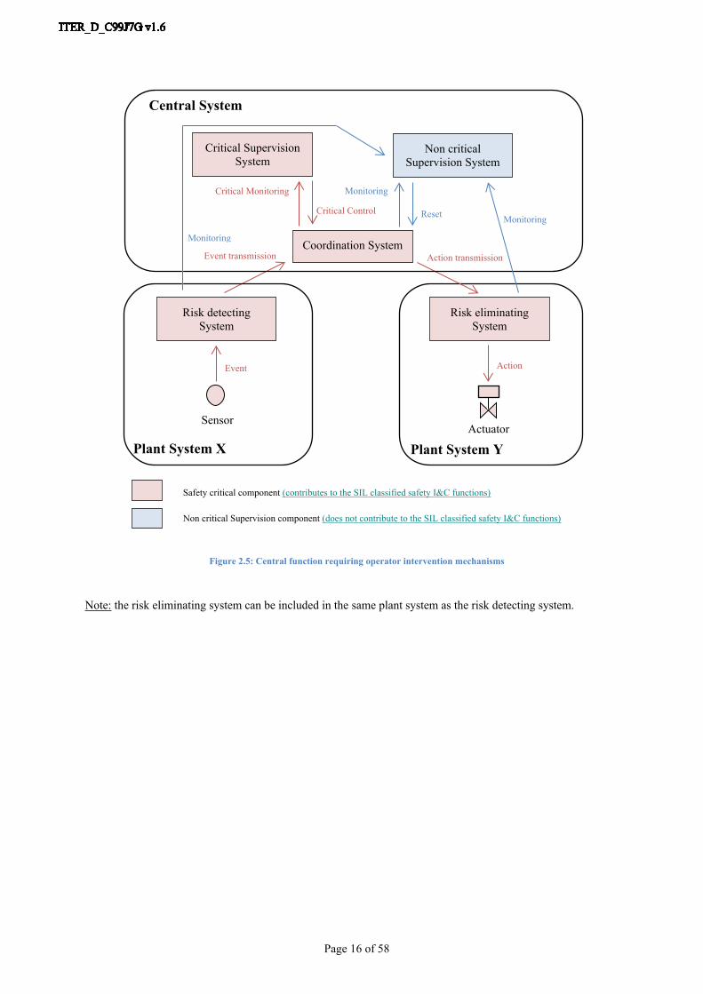
2.3.3 Central OS function – Manual activationSome safety functions require an operator to take a safety decision to trigger a safety action. In this case, the occupational safety events are detected by the plant system(s) and transmitted to the central OS I&C system which alerts the safety operator through a very reliable HMI. This HMI allows commands to be executed on the central system which in turn dispatches the required safety actions to the plant system(s).The central system contributes to the safety integrity level of these functions. Together the plant systems providing part of the function and the central system must achieve the required safety integrity level according to the applicable standards [AS1] and [AS2].The central I&C system for occupational safety is responsible for the critical monitoring and critical control of the functions which require a safety integrity level and for the supervisory features that do not require a safety integrity level.
Page 16 of 58
Monitoring
Monitoring
Critical Monitoring
Critical Control
Plant System Y
Monitoring
Reset
Plant System X
Event transmission
ActionEvent
ActuatorSensor
Critical Supervision System
Non critical Supervision System
Coordination System
Risk detecting System
Risk eliminating System
Action transmission
Central System
Safety critical component (contributes to the SIL classified safety I&C functions)
Non critical Supervision component (does not contribute to the SIL classified safety I&C functions)
Figure 2.5: Central function requiring operator intervention mechanisms
Note: the risk eliminating system can be included in the same plant system as the risk detecting system.

Page 17 of 58
3 SCS-OS Introduction
To cope with OS requirements, the CSS-OS System is composed of a safety logic system (to coordinate OS central functions) and a SCADA system (to supervise all OS I&C functions and all system functions).The following sections focus on the different OS human machine interfaces designed to be used by the various OS actors.Note: The elements are described here mainly for information purposes, as the PSS-OS designer will finally build the interface with those components, even if in some cases it is an indirect interface.
3.1 OS HMIsThere are four dedicated human machine interfaces for the occupational safety System:
- Operating terminals (or CSS-OS terminals),- Safety critical hardwired HMI,- Maintenance terminals,- Engineering workstation.
Figure 3.1: OS HMIs and associated components
Caution: redundancy of Control Rooms and Server Rooms are not represented in figure 3.1.
The figure above focuses on the different human machine interfaces (the other CSS-OS components are not represented).

Page 18 of 58
The routine access to the various PSS-OS is done from the control and server rooms using the SCS-OS infrastructure. The PSS-OS will mainly connect to two interfacing components: the CSS-OS Safety PLC associated with the safety critical hardwired HMI (coordination purpose for OS I&C Central functions) and the CSS-OS SCADA server (supervision purpose for the SCS-OS).
3.1.1 CSS-OS Operational ComponentsThere are two types of operational component:
The Safety Critical Hardwired HMI, The OS SCADA.
3.1.1.1 Safety Critical Hardwired HMIWhen the monitoring (or control) impacts on the triggering of safety actions and also requires a safety level (SIL), a very reliable (hardwired) supervisory device will be designed.It may be required for “not fully automatic” high occupational risks that require a human response (i.e. command) to trigger the safety function, or to display critical occupational safety function alarms or states.The redundant safety critical hardwired HMIs are located in the control rooms and are connected to the CSS-OS Safety PLC through specific redundant remote I/O stations.
3.1.1.2 OS SCADAThe Operating part of OS SCADA is represented by the CSS-OS terminals located in the control rooms. They support the monitoring (and control) and have no impact on the actuation of an OS function. Support is via:
OS functional views (Global and detailed), Alarm list views, Archived data list views.
The SCS-OS is mainly an automatic system with more supervision than control for Safety operator. About the control part, the main action of the operator in Control Room is the reset command. The OS reset commands are sent by authorised operators from the CSS-OS operating terminals using the OS functional detailed views. These commands are needed for OS operation but cannot modify the critical machine protection configuration of the PSS-OS. They are transmitted to the PSS-OS logic via the redundant CSN-OS.
The CSS-OS terminals also permit override operations. The Safety operator manages override operations through two parallel ways on the CSS-OS Operating terminal:
through alarm management in dedicated SCADA area and associated alarms (maintenance override set, maintenance override reset, time delay out),
through synthesis of OS function state (via specific color code for example).
From the operator interface requirements of IEC 61511-1:“The SIS status information that is critical to maintaining the SIL shall be available as part of the operator interface. This information may include:
where the process is in its sequence; indication that SIS protective action has occurred; indication that a protective function is bypassed; indication that automatic action(s) such as degradation of voting and/or fault handling has occurred; status of sensors and final elements; the loss of energy where that energy loss impacts safety;
Page 19 of 58
the results of diagnostics; failure of environmental conditioning equipment which is necessary to support the SIS”
Warning: critical adjective is oriented and so interpreted differently between PBS48 OS and IEC standards. Concerning PBS48 OS, critical adjective is used to make the difference between central I&C system components according to their SIL oriented contribution (supervision systems for example). On the other hand, IEC standards are using critical term instead of very important or essential (the SIS status information that is essential to maintaining the SIL).
3.1.2 CSS-OS Maintenance ComponentsThere are two types of maintenance component:
The CSS-OS maintenance terminals, The CSS-OS engineering workstation.
3.1.2.1 CSS-OS Maintenance TerminalsThrough the specific CSS-OS terminals located in the server rooms, SCS-OS displays the detailed state of the occupational safety system to the maintenance team via:
PLC hardware diagnostic supervision views, Cubicle hardware diagnostic supervision views, Network component hardware diagnostic supervision views, Inter-systems communication diagnostic supervision views.
3.1.2.2 CSS-OS Engineering workstationAn engineering workstation is necessary for changing PLC application configuration and online monitoring. This station contains the off-line version of the application running inside all PLC of CSS-OS and PSS-OS.Note: For security purpose, this component will be disconnected during operation phase.

Page 20 of 58
4 PSS-OS Architectures
The PSS-OS shall be designed by taking into account the following requirements: Safety requirements specified in the safety I&C function specifications (safety function description, safe
state definition, requirements for proof-test intervals, response time requirements, safety integrity level, maximum allowable spurious trip rate, requirements for overrides…),
IEC 61508 / 61511 Functional Safety standards requirements, Integration requirements specified in the safety functions specifications or in [RD1] – Plant Control
Design Handbook [ITER_D_27LH2V] and its satellite documents like [RD13] – ITER Catalogue for Slow controllers [ITER_D333J63].
ITER selection for slow controllers is S7 Fail-safe systems from SIEMENS catalogue.In SIEMENS products, two fail-safe systems are available for integrating safety engineering into SIMATIC S7 automation:
The S7 Distributed safety System is available to implement safety concepts for machine and operator protections (e.g. for emergency stop devices for operation of machine tools and processing machine) and the process industry (e.g. for protection functions for instrumentation and control protective devices and burners),
The S7 F/FH System is well-suited for process engineering and oil industry as it is a fail-safe and optionally fault-tolerant automation system.
Note: The hardware components and software tools required for configuring and operating S7 Distributed Safety and S7 F/FH Systems are specific to each type of S7 Fail-safe system.
Refer to section 9.1.2 – SIMATIC S7 Fail-safe systems comparison to get main comparison criteria between the two systems.
The following table resumes the main hardware components selected by PBS48 OS.
S7 Fail-safe System SIMATIC S7 Distributed Safety System
SIMATIC S7 F/FH System
CPU controller series S7-300F S7-400H
Remote I/O station S7 ET200M
I/O modules S7 300 Safety modules (F modules)
Table 4.1: PBS48 OS selected components
Based on the above selection, PBS48 proposes four PSS-OS architectures: PSS-OS with centralized I/O based on S7 Distributed Safety Fail-safe system, PSS-OS with remote I/O based on S7 Distributed Safety Fail-safe system, PSS-OS with remote I/O based on F/FH Fail-safe system, Fault-tolerant PSS-OS based on F/FH Fail-safe system.
Before describing the different PSS-OS architectures, it is necessary to list design requirements about PSS-OS architecture management:
1. Ideally one plant system shall contain only one PSS-OS architecture.
Page 21 of 58
2. It is not recommended but in some special cases (due to application size and complexity, or distribution throughout the site) one plant system may host more than one PSS-OS architecture. In this case, whenever possible, only one PSS-OS architecture in the plant system is connected to the CSS-OS via the CSN-OS. This means that additional requirements may be set on this PSS-OS: integrity level, availability, response time, etc. in order to fulfil safety requirements.
4.1 PSS-OS with centralized I/O based on S7 Distributed Safety Fail-safe system architecture
This architecture is recommended for the implementation of local Occupational Safety I&C functions up to SIL2.Caution: For technical reasons, this architecture is not allowed for the implementation of central Occupational safety I&C function (refer to section 9.1.1 for explanations).
General requirements for this architecture are: A single CPU, Safety I/O modules, A redundant connection with the redundant occupational safety central networks.
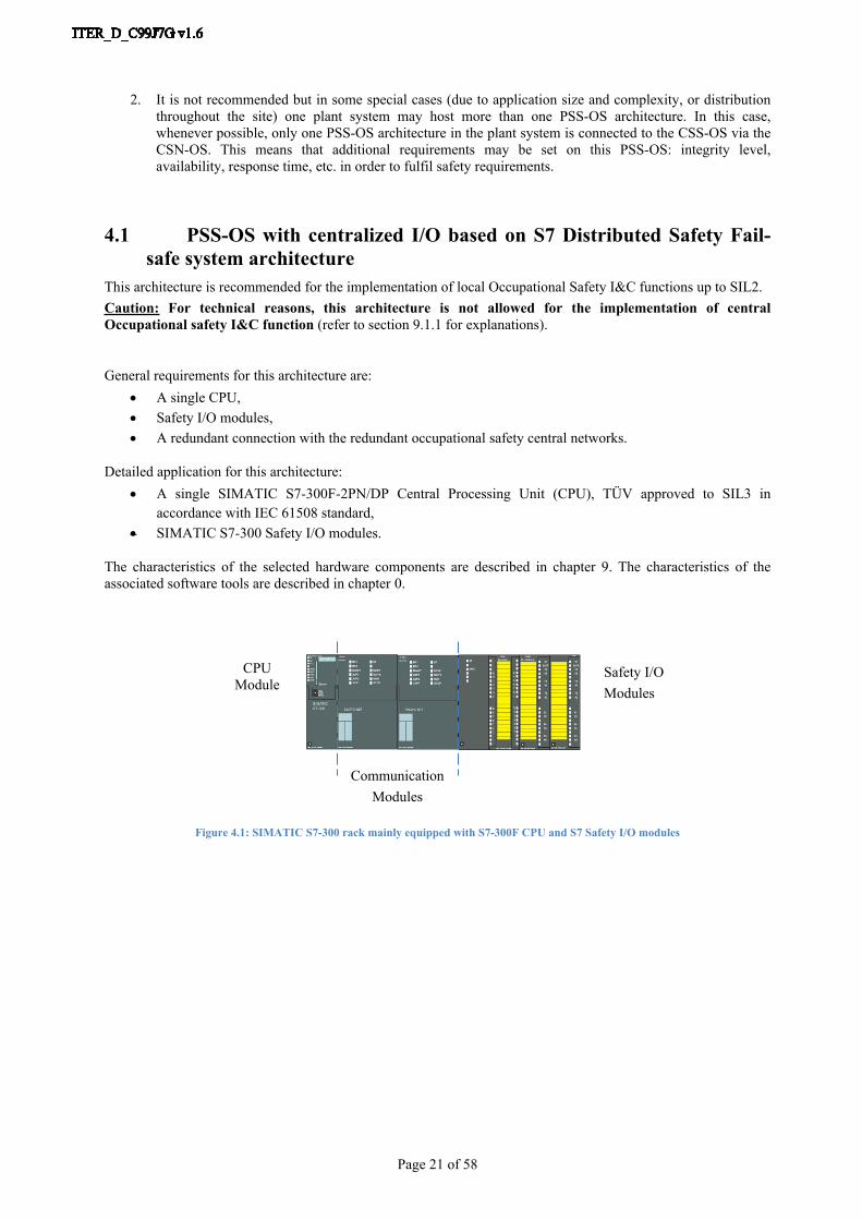
Detailed application for this architecture: A single SIMATIC S7-300F-2PN/DP Central Processing Unit (CPU), TÜV approved to SIL3 in
accordance with IEC 61508 standard, SIMATIC S7-300 Safety I/O modules.
The characteristics of the selected hardware components are described in chapter 9. The characteristics of the associated software tools are described in chapter 0.
CPUModule
Safety I/O Modules
CommunicationModules
Figure 4.1: SIMATIC S7-300 rack mainly equipped with S7-300F CPU and S7 Safety I/O modules
Page 22 of 58
CSN – OS1 I&C Architecture
PSS-OS
CSN – OS2
SENSORSACTUATORS
CSS-OSSCADA Servers
SIMATIC S7CPU 300F2 PN/DP
Hardwired connection
CSS-OS Network 1
CSS-OS Network 2
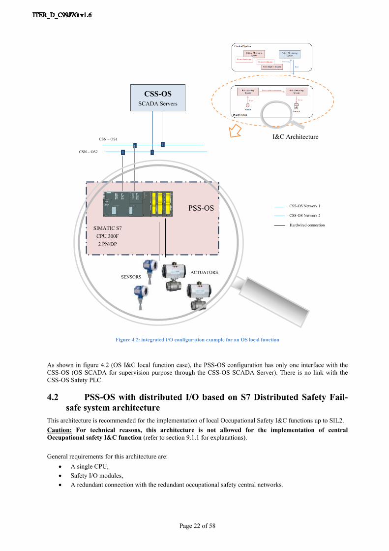
Figure 4.2: integrated I/O configuration example for an OS local function
As shown in figure 4.2 (OS I&C local function case), the PSS-OS configuration has only one interface with the CSS-OS (OS SCADA for supervision purpose through the CSS-OS SCADA Server). There is no link with the CSS-OS Safety PLC.
4.2 PSS-OS with distributed I/O based on S7 Distributed Safety Fail-safe system architecture
This architecture is recommended for the implementation of local Occupational Safety I&C functions up to SIL2.Caution: For technical reasons, this architecture is not allowed for the implementation of central Occupational safety I&C function (refer to section 9.1.1 for explanations).
General requirements for this architecture are: A single CPU, Safety I/O modules, A redundant connection with the redundant occupational safety central networks.
Page 23 of 58
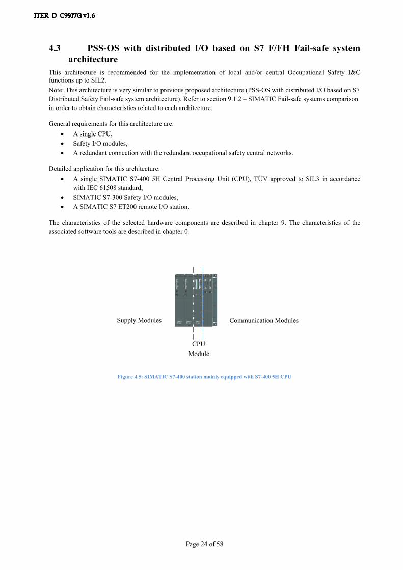
Detailed application for this architecture: A single SIMATIC S7-300F-2PN/DP Central Processing Unit (CPU), TÜV approved to SIL3 in
accordance with IEC 61508 standard, SIMATIC S7-300 Safety I/O modules, A SIMATIC S7 ET200 remote I/O station.
The characteristics of the selected hardware components are described in chapter 9. The characteristics of the associated software tools are described in chapter 0.
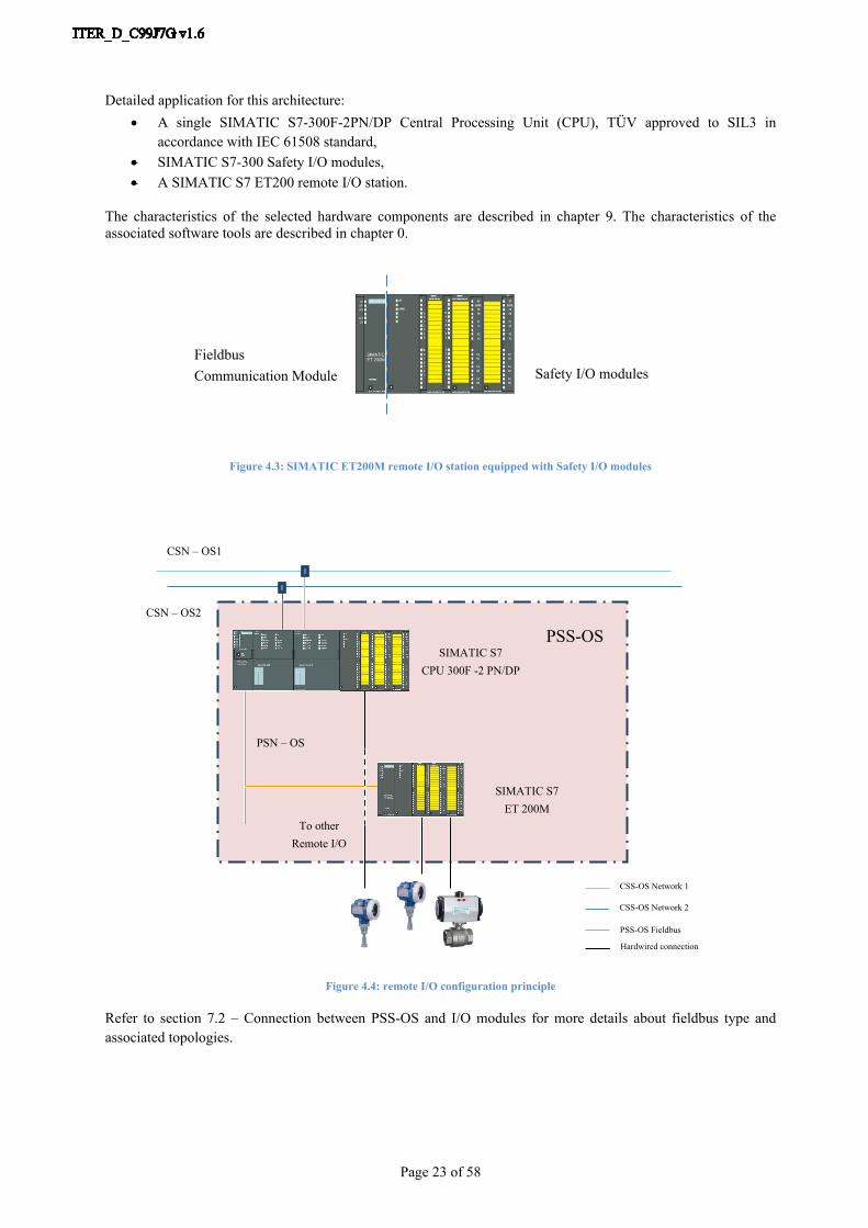
Safety I/O modulesFieldbusCommunication Module
Figure 4.3: SIMATIC ET200M remote I/O station equipped with Safety I/O modules
CSN – OS2
PSN – OS
PSS-OS
CSN – OS1
SIMATIC S7ET 200M
To otherRemote I/O
SIMATIC S7CPU 300F -2 PN/DP
Hardwired connection
PSS-OS Fieldbus
CSS-OS Network 1
CSS-OS Network 2
Figure 4.4: remote I/O configuration principle
Refer to section 7.2 – Connection between PSS-OS and I/O modules for more details about fieldbus type and associated topologies.
Page 24 of 58
4.3 PSS-OS with distributed I/O based on S7 F/FH Fail-safe system architecture
This architecture is recommended for the implementation of local and/or central Occupational Safety I&C functions up to SIL2.Note: This architecture is very similar to previous proposed architecture (PSS-OS with distributed I/O based on S7 Distributed Safety Fail-safe system architecture). Refer to section 9.1.2 – SIMATIC Fail-safe systems comparison in order to obtain characteristics related to each architecture.
General requirements for this architecture are: A single CPU, Safety I/O modules, A redundant connection with the redundant occupational safety central networks.
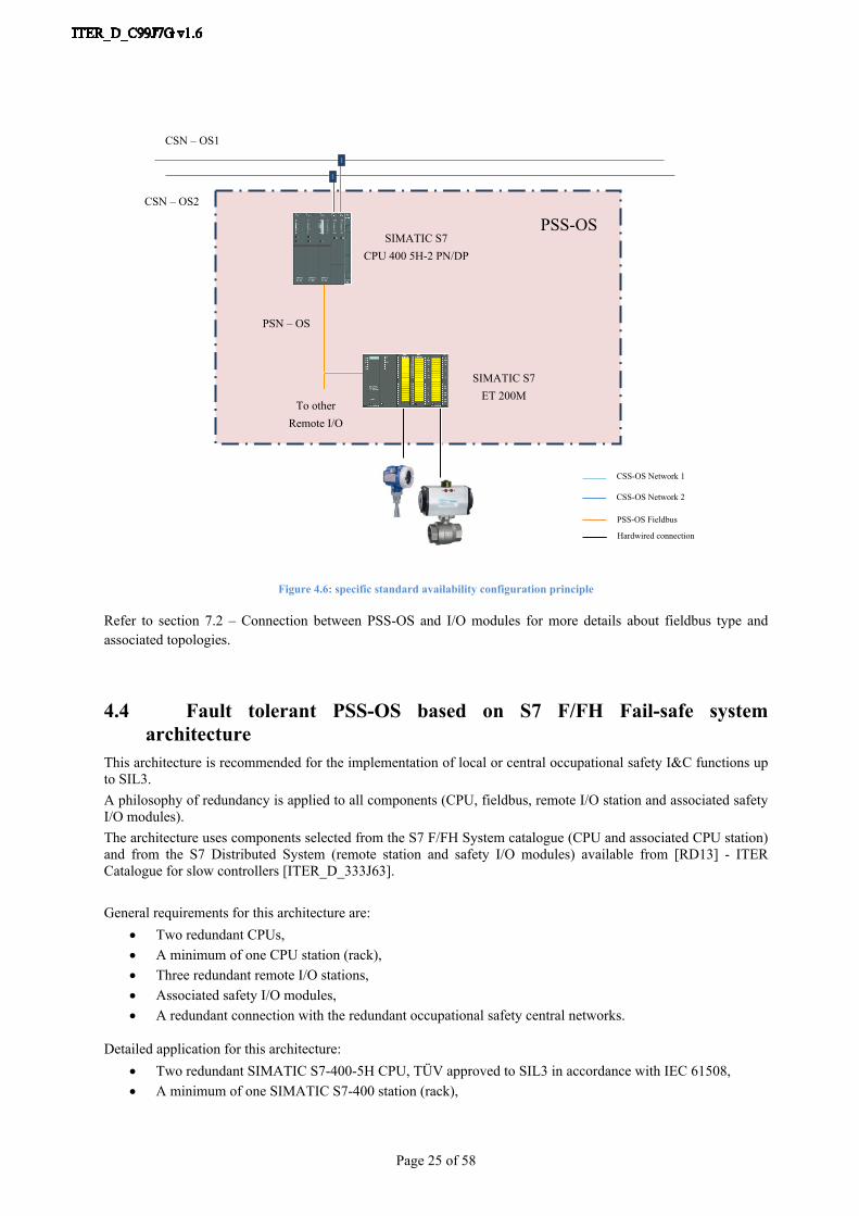
Detailed application for this architecture: A single SIMATIC S7-400 5H Central Processing Unit (CPU), TÜV approved to SIL3 in accordance
with IEC 61508 standard, SIMATIC S7-300 Safety I/O modules, A SIMATIC S7 ET200 remote I/O station.
The characteristics of the selected hardware components are described in chapter 9. The characteristics of the associated software tools are described in chapter 0.
Communication ModulesSupply Modules
CPUModule
Figure 4.5: SIMATIC S7-400 station mainly equipped with S7-400 5H CPU
Page 25 of 58
SIMATIC S7CPU 400 5H-2 PN/DP
CSN – OS2
PSN – OS
PSS-OS
CSN – OS1
SIMATIC S7ET 200M
To otherRemote I/O
Hardwired connection
PSS-OS Fieldbus
CSS-OS Network 1
CSS-OS Network 2
Figure 4.6: specific standard availability configuration principle
Refer to section 7.2 – Connection between PSS-OS and I/O modules for more details about fieldbus type and associated topologies.
4.4 Fault tolerant PSS-OS based on S7 F/FH Fail-safe system architecture
This architecture is recommended for the implementation of local or central occupational safety I&C functions up to SIL3.A philosophy of redundancy is applied to all components (CPU, fieldbus, remote I/O station and associated safety I/O modules).The architecture uses components selected from the S7 F/FH System catalogue (CPU and associated CPU station) and from the S7 Distributed System (remote station and safety I/O modules) available from [RD13] - ITER Catalogue for slow controllers [ITER_D_333J63].
General requirements for this architecture are: Two redundant CPUs, A minimum of one CPU station (rack), Three redundant remote I/O stations, Associated safety I/O modules, A redundant connection with the redundant occupational safety central networks.
Detailed application for this architecture: Two redundant SIMATIC S7-400-5H CPU, TÜV approved to SIL3 in accordance with IEC 61508, A minimum of one SIMATIC S7-400 station (rack),
Page 26 of 58
Three redundant SIMATIC ET200M remote I/O stations equipped with associated S7-300 Safety I/O modules (2oo3 evaluation case for sensors and 1oo3 evaluation case for actuators).
Each redundant CPU is connected to only one redundant CSN-OS network (CSN-OS 1 or CSN-OS 2).
There are two possibilities for the redundant CPUs layout. The first option has each CPU located in separate stations and also in a specific cubicle. The second option has the two redundant CPUs located in only one cubicle and in the same station. The point about the second option is the common cause failure provoked by an event affecting both CPUs, such as fire in the cubicles.
The characteristics of the selected hardware components are described in chapter 9. The characteristics of the associated software tools are described in chapter 0.
Note: CPU redundancy principle is active redundancy. Programs in both CPUs are identical and executed synchronously by each of them.
Refer to section 8.2 – Connection between PSS-OS and I/O modules for more details about available fieldbus type and associated topologies.

Page 27 of 58
SIMATIC S7CPU 400-5H
CSN – OS2
PSN – OS1PROFIBUS
PSS-OS
CSN – OS1
REDUNDANTSIMATIC S7
ET 200M
SIMATIC S7ET 200M
REDUNDANTSIMATIC S7CPU 400-5H
PSN – OS2PROFIBUS
REDUNDANTSIMATIC S7
ET 200M
Hardwired connection
PSS-OS Fieldbus 1
CSS-OS Network 1
CSS-OS Network 2
PSS-OS Fieldbus 2
Figure 4.7: redundant I/O configuration principle
Page 28 of 58
OS function response time
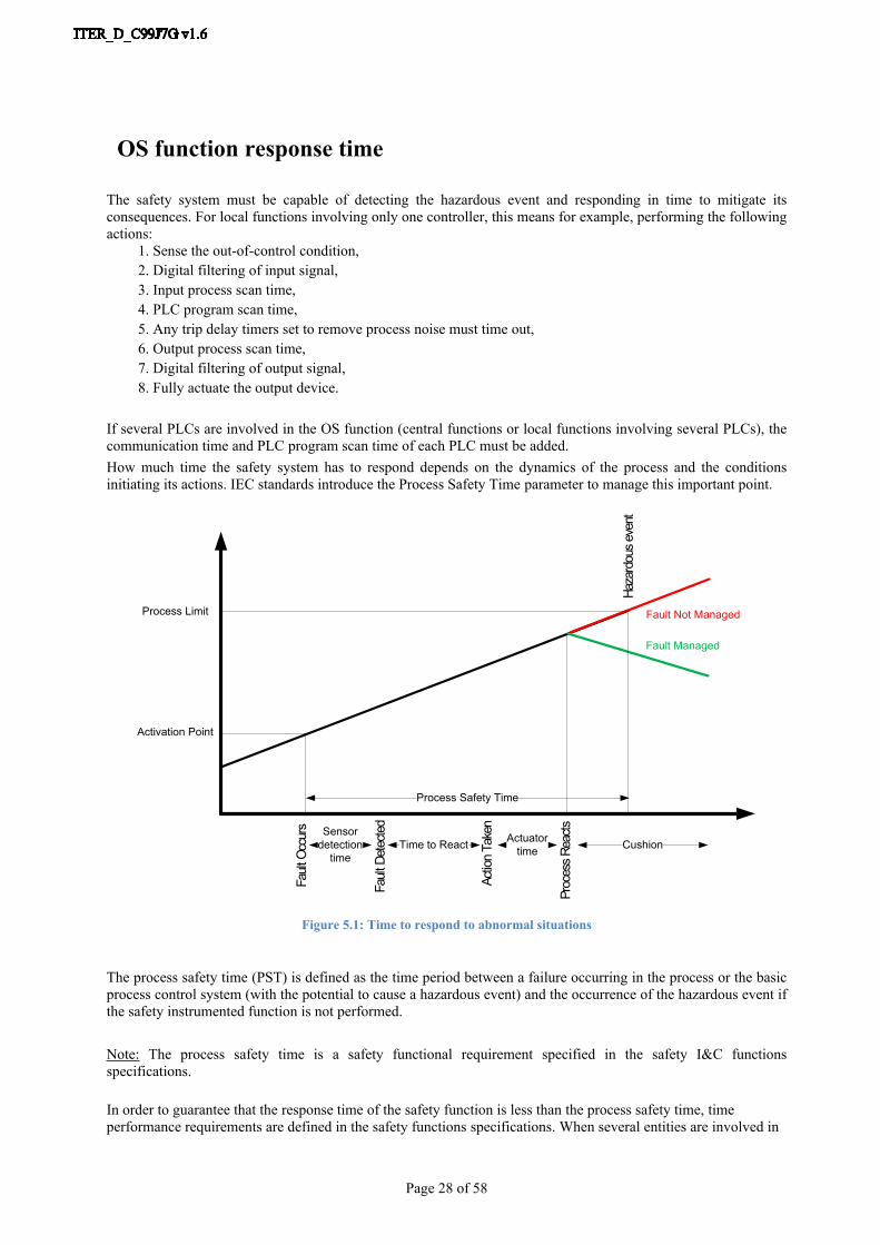
The safety system must be capable of detecting the hazardous event and responding in time to mitigate its consequences. For local functions involving only one controller, this means for example, performing the following actions:
1. Sense the out-of-control condition,2. Digital filtering of input signal,3. Input process scan time,4. PLC program scan time,5. Any trip delay timers set to remove process noise must time out,6. Output process scan time,7. Digital filtering of output signal,8. Fully actuate the output device.
If several PLCs are involved in the OS function (central functions or local functions involving several PLCs), the communication time and PLC program scan time of each PLC must be added.How much time the safety system has to respond depends on the dynamics of the process and the conditions initiating its actions. IEC standards introduce the Process Safety Time parameter to manage this important point.
Fault
Occ
urs
Fault
Det
ecte
d
Actio
n Ta
ken
Fault Not Managed
Fault Managed
Sensor detection
timeTime to React Actuator
time Cushion
Process Safety Time
Proc
ess R
eacts
Haza
rdou
s eve
nt
Activation Point
Process Limit
Figure 5.1: Time to respond to abnormal situations
The process safety time (PST) is defined as the time period between a failure occurring in the process or the basic process control system (with the potential to cause a hazardous event) and the occurrence of the hazardous event if the safety instrumented function is not performed.
Note: The process safety time is a safety functional requirement specified in the safety I&C functions specifications.
In order to guarantee that the response time of the safety function is less than the process safety time, time performance requirements are defined in the safety functions specifications. When several entities are involved in

Page 29 of 58
the implementation of a safety I&C function, the safety I&C function may be decomposed in sub-functions in order to assign unambiguously the scope of the different entities involved and the time performance requirement for the accomplishment of the assigned part of the safety function.
Page 30 of 58
Periodic tests requirements
The objective of operation and maintenance phase of Safety System is the mastery over time of integrity level of each Safety functions.Periodic tests allow to manage dangerous failures (undetected by diagnostics) in order to maintain Safety Functions in the probability of failure defined in the risk analysis phase.These tests can be done either partially or totally, but shall cover the entire Safety System.From IEC 61511 part 1 section 16.3.1:“The entire SIS shall be tested including the sensor(s), the logic solver and the final element(s)”
Contrary to ITER experimental process which is not continuous, SCS-OS (PSS-OS and CSS-OS) shall operate in continue to protect people and environment knowing that process maintenance period are sometimes more critical than operational period (OS functions are generally linked to people presence).
It’s the reason why, the process to perform the periodic tests that are required to maintain the SIL level of the PSS-OS functions has to be considered at the design stage. The requirements of the OS I&C functions have to take into account provisions for performing the tests during the PSS-OS operation (additional redundancies, specific overrides…).
Warning: For each Safety function, the no respect of periodic tests directly impacts the associated quantitative requirement (PFD or PFH) and consequently the SIL level.From IEC 61511 Part 1 section 16.3.1.3:“The frequency of the proof tests shall be as decided using the PFD average calculation”
Refer to [RD8] - Guidelines for PSS-OS Reliability Assessment [ITER_D_HXQ35R] for more details about association between periodic test and failure calculation.
Page 31 of 58
7 Sensors and actuators
Each Plant System must follow various requirements in order to select sensors and actuators: The SIEMENS requirements associated to F-modules, The IEC 61508 / 61511 Functional Safety standards requirements associated to sensor / actuator sub-
system definition.This chapter presents the SIEMENS F-modules requirements and also the IEC 61508 / IEC 61511 concepts to considered in parallel to IEC requirements.Refer to [RD8] - Guidelines for PSS-OS Reliability Assessment [ITER_D_HXQ35R] for more details about IEC requirements.
7.1 SIMATIC F-modules requirementsPlant System designer must check compatibility between SIEMENS F-modules and pre-selected sensors & actuators for the following purpose:
Minimum of duration for sensor signal to obtain a correct acquisition, Actuator reaction according to F-modules test pulse to avoid undesired action.
Refer to [RD27] – SIMATIC Distributed I/O device Fail-safe signals modules (section 5.4) for more details.
7.2 IEC standards conceptsSuitably qualified sensors and actuators are necessary to achieve the safety integrity level of the OS I&C functions.Complementary to quantitative & architectural requirements (Probability of failure and Hardware Fault tolerance requirements), several concepts introduced by IEC standards should be taken into account for sensors and actuators selection and design:
Fail-safe concept, Proven in use concept, Diversity concept.
7.2.1 Fail-safe concept
7.2.1.1 DefinitionIn the event of a failure, a fail-safe device or system will automatically permit to switch to a pre-determined safe state. In other words, failure is not dangerous.Examples:
In the case of a sensor failure, the system detects it through the use of signal monitoring. As result, the system automatically triggers the function in order to switch to safe state.
In the case of a fail-safe sensor failure, fault is diagnosed and the sensor passes into the defined safe-state. As result, the system automatically triggers the function.
In the case of loss of utilities, actuator will automatically switch to safe state thanks to it safe position.
7.2.1.2 PrinciplesApart from some specific cases, the design of Plant System shall follow principles associated to fail-safe concept. The main principles are de-energized to trip concept and signal monitoring concept.
Page 32 of 58
1. The safe position and the de-energized position of an actuator shall be the same. The safe position of an actuator is reached when the power to that actuator is switched off. So, in the event of power failure, all the PLC outputs (actuators commands) go to the de-energized condition therefore putting the actuators in the safe position. When the power is restored all outputs must remain de-energized until appropriate resets.
2. In order to compensate specific inputs/outputs that are energized-to-trip (not fail-safe), health monitoring on the line (supervised digital input and supervised digital output) shall be used.
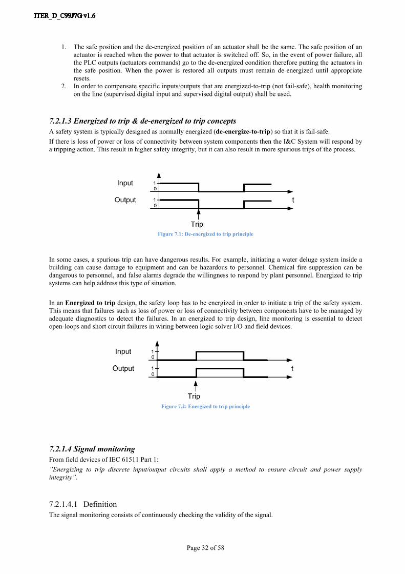
7.2.1.3 Energized to trip & de-energized to trip conceptsA safety system is typically designed as normally energized (de-energize-to-trip) so that it is fail-safe.If there is loss of power or loss of connectivity between system components then the I&C System will respond by a tripping action. This result in higher safety integrity, but it can also result in more spurious trips of the process.
Figure 7.1: De-energized to trip principle
In some cases, a spurious trip can have dangerous results. For example, initiating a water deluge system inside a building can cause damage to equipment and can be hazardous to personnel. Chemical fire suppression can be dangerous to personnel, and false alarms degrade the willingness to respond by plant personnel. Energized to trip systems can help address this type of situation.
In an Energized to trip design, the safety loop has to be energized in order to initiate a trip of the safety system. This means that failures such as loss of power or loss of connectivity between components have to be managed by adequate diagnostics to detect the failures. In an energized to trip design, line monitoring is essential to detect open-loops and short circuit failures in wiring between logic solver I/O and field devices.
Figure 7.2: Energized to trip principle
7.2.1.4 Signal monitoringFrom field devices of IEC 61511 Part 1:”Energizing to trip discrete input/output circuits shall apply a method to ensure circuit and power supply integrity”.
7.2.1.4.1 DefinitionThe signal monitoring consists of continuously checking the validity of the signal.
Page 33 of 58
First of all, it is important to differentiate between a contact normally opened and an opened contact due to a fault such as an open loop. In the same way, it is important to make the difference between a closed contact and a short circuit.The signal monitoring also allows a maintenance action to be launched when a signal is not valid. In this way the signal can be repaired and the I&C system will be fully operational again.
7.2.1.4.2 Application
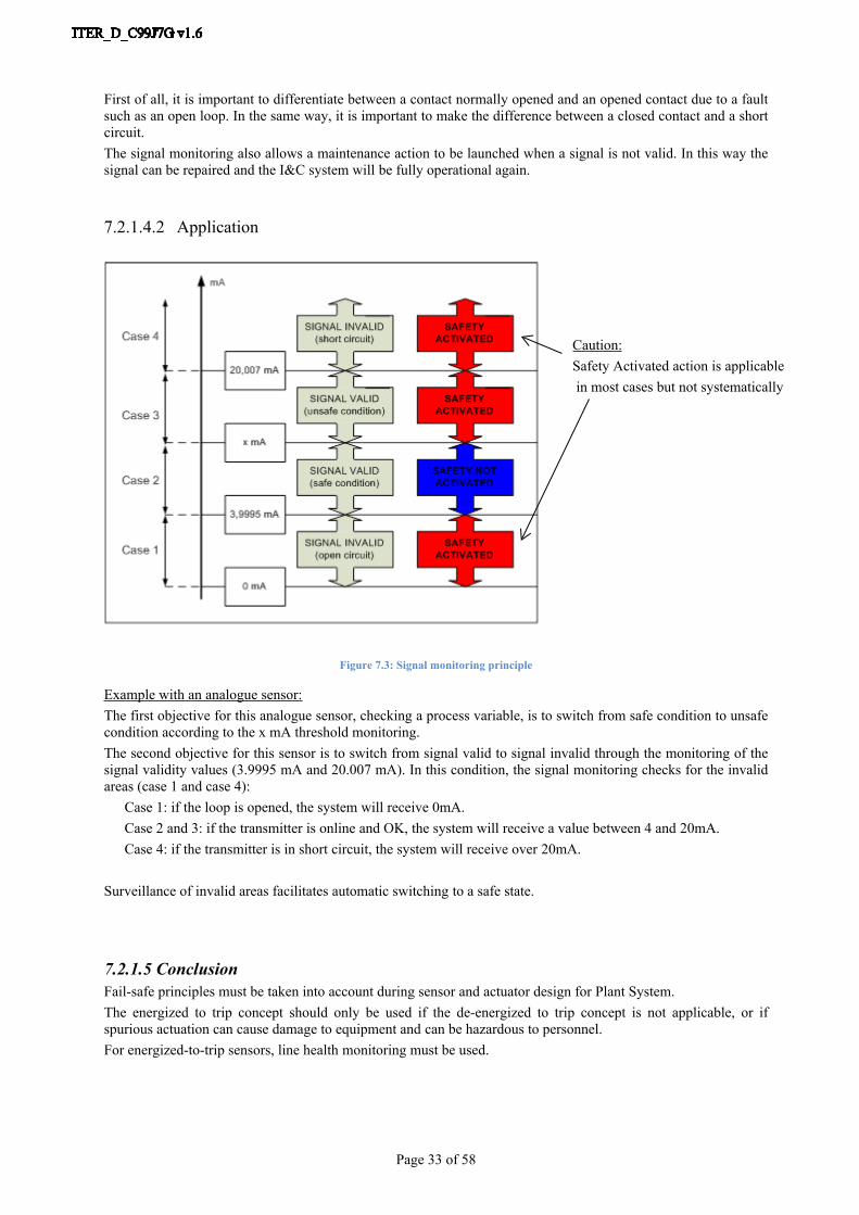
Caution:Safety Activated action is applicable in most cases but not systematically
Figure 7.3: Signal monitoring principle
Example with an analogue sensor:The first objective for this analogue sensor, checking a process variable, is to switch from safe condition to unsafe condition according to the x mA threshold monitoring.The second objective for this sensor is to switch from signal valid to signal invalid through the monitoring of the signal validity values (3.9995 mA and 20.007 mA). In this condition, the signal monitoring checks for the invalid areas (case 1 and case 4):
Case 1: if the loop is opened, the system will receive 0mA.Case 2 and 3: if the transmitter is online and OK, the system will receive a value between 4 and 20mA.Case 4: if the transmitter is in short circuit, the system will receive over 20mA.
Surveillance of invalid areas facilitates automatic switching to a safe state.
7.2.1.5 ConclusionFail-safe principles must be taken into account during sensor and actuator design for Plant System.The energized to trip concept should only be used if the de-energized to trip concept is not applicable, or if spurious actuation can cause damage to equipment and can be hazardous to personnel.For energized-to-trip sensors, line health monitoring must be used.

Page 34 of 58
7.2.2 Proven in use conceptTo compensate for the small number of SIL capable components available, Plant System designer can rely on Proven in Use concept. Sensor or actuators are declared Proven in use when a documented assessment has shown that there is appropriate evidence, based on the previous use of the component (in safety or non-safety applications), that the component is suitable for use.The documentary evidence shall demonstrate that the previous conditions of use of the component are the same as, or sufficiently close to, those which will be experienced by the newly considered operating environment. The failures should be documented and reported, equipment items must be clearly specified and the equipment item manufacturer should have appropriate quality management and configuration management procedures in place.
From IEC 61511 Part 2 Section 11.5.3.1:“There are very few field devices (sensors and valves) that are designed per IEC 61508-2 and IEC 61508-3. Users and designers will therefore have to depend more heavily on using field devices that have been “proven-in-use.”
From IEC 61511 Part 1 Section 11.5.3.1:“Appropriate evidence shall be available that the components and subsystems are suitable for use in the safety instrumented system”.
Refer to [AS2] - IEC 61511 standard parts 1 & 2 section 11.5.3 for all the details about Proven in use requirements.
7.2.3 Diversity conceptTo limit common mode of failure, whenever possible, the choice of redundant instruments should be diversified (use of different technologies or different manufacturers).
From IEC 61508 Part 7 Annex B1.4:“Different types of components are used for the diverse channels of a safety-related system. This reduces the probability of common cause failures (for example overvoltage, electromagnetic interference), and increases the probability of detecting such failures.”
Page 35 of 58
8 Networks and communications
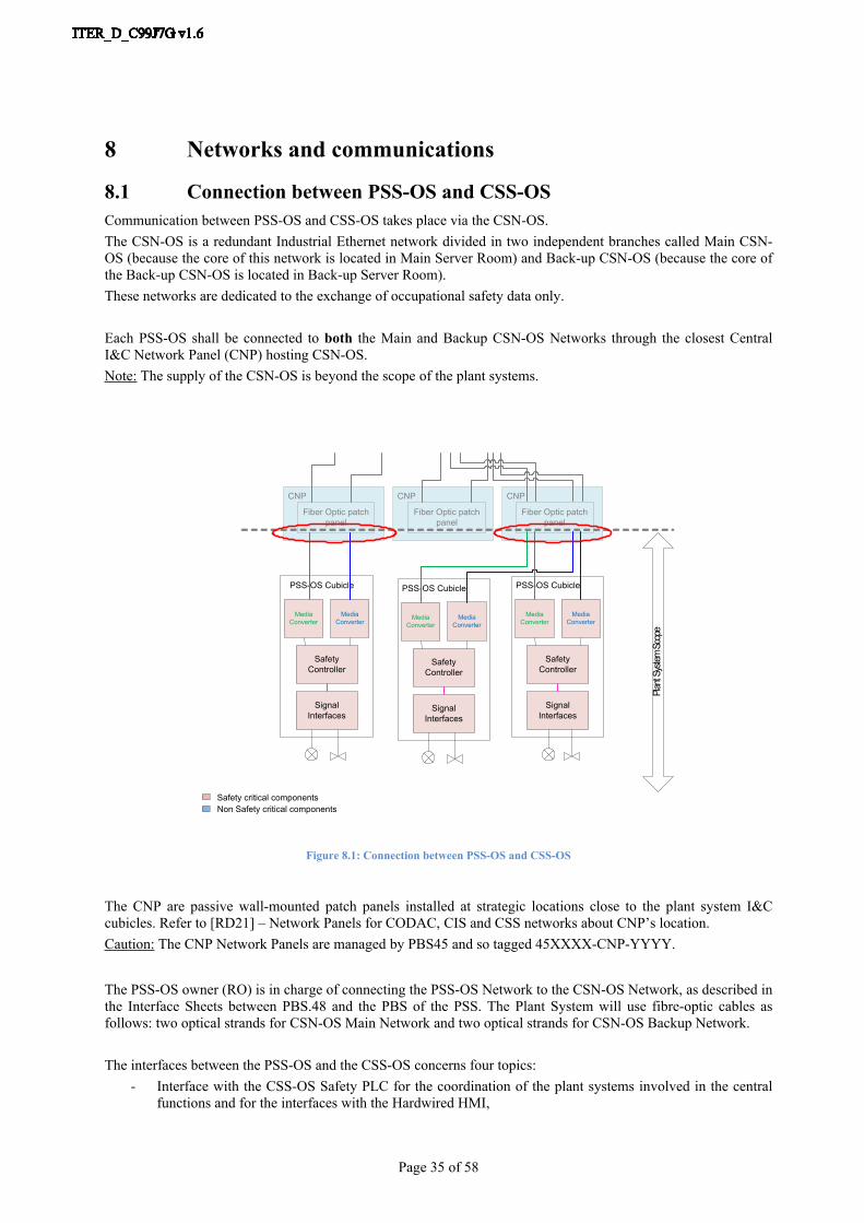
8.1 Connection between PSS-OS and CSS-OSCommunication between PSS-OS and CSS-OS takes place via the CSN-OS.The CSN-OS is a redundant Industrial Ethernet network divided in two independent branches called Main CSN-OS (because the core of this network is located in Main Server Room) and Back-up CSN-OS (because the core of the Back-up CSN-OS is located in Back-up Server Room).These networks are dedicated to the exchange of occupational safety data only.
Each PSS-OS shall be connected to both the Main and Backup CSN-OS Networks through the closest Central I&C Network Panel (CNP) hosting CSN-OS. Note: The supply of the CSN-OS is beyond the scope of the plant systems.
PSS-OS Cubicle
Signal Interfaces
CNP CNP
Fiber Optic patch panel
PSS-OS Cubicle
Signal Interfaces
Safety Controller
Safety Controller
Plant
Syste
m Sc
ope
Fiber Optic patch panel
Media Converter
Media Converter
Media Converter
Media Converter
PSS-OS Cubicle
Signal Interfaces
Safety Controller
Media Converter
Media Converter
CNP
Fiber Optic patch panel
Safety critical componentsNon Safety critical components
Figure 8.1: Connection between PSS-OS and CSS-OS
The CNP are passive wall-mounted patch panels installed at strategic locations close to the plant system I&C cubicles. Refer to [RD21] – Network Panels for CODAC, CIS and CSS networks about CNP’s location.Caution: The CNP Network Panels are managed by PBS45 and so tagged 45XXXX-CNP-YYYY.
The PSS-OS owner (RO) is in charge of connecting the PSS-OS Network to the CSN-OS Network, as described in the Interface Sheets between PBS.48 and the PBS of the PSS. The Plant System will use fibre-optic cables as follows: two optical strands for CSN-OS Main Network and two optical strands for CSN-OS Backup Network.
The interfaces between the PSS-OS and the CSS-OS concerns four topics:- Interface with the CSS-OS Safety PLC for the coordination of the plant systems involved in the central
functions and for the interfaces with the Hardwired HMI,
Page 36 of 58
- Interface with the CSS-OS SCADA servers for the supervisory control and data acquisition of the PSS-OS information,
- Interface with the CSS-OS Engineering Workstations for specific maintenance features like modification of PLC configuration,
- Interface with the CSS-OS NTP server for synchronization purpose.
Note 1: Refer to chapter 9 about OS network components requirements.
8.1.1 Interface with the CSS-OS Safety PLCThe scope of this interface is limited to occupational safety central I&C function implementation.The safety-related communication between the PSS-OS and the CSS-OS PLC is based on S7 fault-tolerant connections.Based on redundant communications system, the dedicated S7 fault-tolerant connections allow safety-related communication (CPU-CPU communication) between two S7 FH Systems or between one S7 FH System and one S7 F Systems.Refer to [RD31] – SIEMENS S7 Safety Engineering System Manual [SIEMENS_A5E00109529-06] for more details about S7 fault-tolerant connections.
8.1.2 Interface with the CSS-OS SCADA serversThe scope of this interface is data exchange between PSS-OS and CSS-OS in order to supervise all occupational safety I&C functions and also all SCS-OS system functions like PSS-OS hardware diagnostic. The CSS-OS SCADA is based on WinCC Open Architecture which is supervisory software for the control room or machine operation and includes a S7 driver for the connection to the periphery with Siemens S7 PLCs.Among TCP/IP drivers proposed by WinCC OA such as ModBus TCP and Ethernet/IP drivers, S7 driver allows communication between WinCC OA SCADA and S7 devices such as S7-300, S7-400 and S7-1200 controllers.
8.1.3 Interface with the CSS-OS Engineering WorkstationThe CSS-OS engineering workstation is connected to CSN-OS to manage PSS-OS PLC software (and also CSS-OS PLC software) through a SIEMENS proprietary protocol.
8.1.4 Interface with the CSS-OS NTP serverThe PSS-OS PLC has to be synchronized with a unique time reference to provide correct logging of the sequence of events for fault analysis.As S7 Siemens PLC accepts NTP synchronization, the CSS-OS provides one or two NTP servers connected to both branches of the CSN-OS.At PSS-OS level, the CP (or CPU according to architecture) sends time queries at regular intervals to CSS-OS NTP server for synchronization.
8.2 Connection between PSS-OS and the I/O modulesWhen ET200M racks are used (for remote I/O connections or for CPU 400H periphery), communication between the PSS-OS and its periphery takes place via the PSN-OS.Safety communication between the safety program in the F-CPU and the fail-safe I/O modules takes place via the standard ProfiBus DP or Profinet IO with superimposed ProfiSafe safety profile using the SIMATIC interface module IM 153-2 HF (Profibus DP) or IM 153-4 HF (Profinet IO).
Note: Preferred option for PBS48 point of view is ProfiBus DP for following reasons:

Page 37 of 58
Simplest option for Fault tolerant architecture between CPU and remote I/O, Segregation purpose between fieldbus and other networks such as Central Safety Networks, Security purpose (read only function for access of a field device), Large return of experience in many sectors (opposite to dedicated Profinet IO components which have
only few years of feedback), No IT requirements (hardware or software).
8.2.1 Profibus DP caseIn this case, the CPU is used as DP master and its Profibus DP interface supports the connection of distributes I/O.
PBS.X Cubicle
CPU CPa
CPb
PSS-OSRack 0
IM0a DIa DOa
DP
DP
MEDIA CONVERTER MEDIA CONVERTER
Sensor a
Actuator a
Actuator b
PSS-OS PeripheryRack 1
DIb
Sensor b
DOb
Bus 0 Profibus DP
Network 1 Industrial Ethernet
Network 0 Industrial Ethernet
RS485
CNPCSN-OS MAIN CSN-OS BACK UP
Figure 8.2: Connection between PSS-OS and an I/O
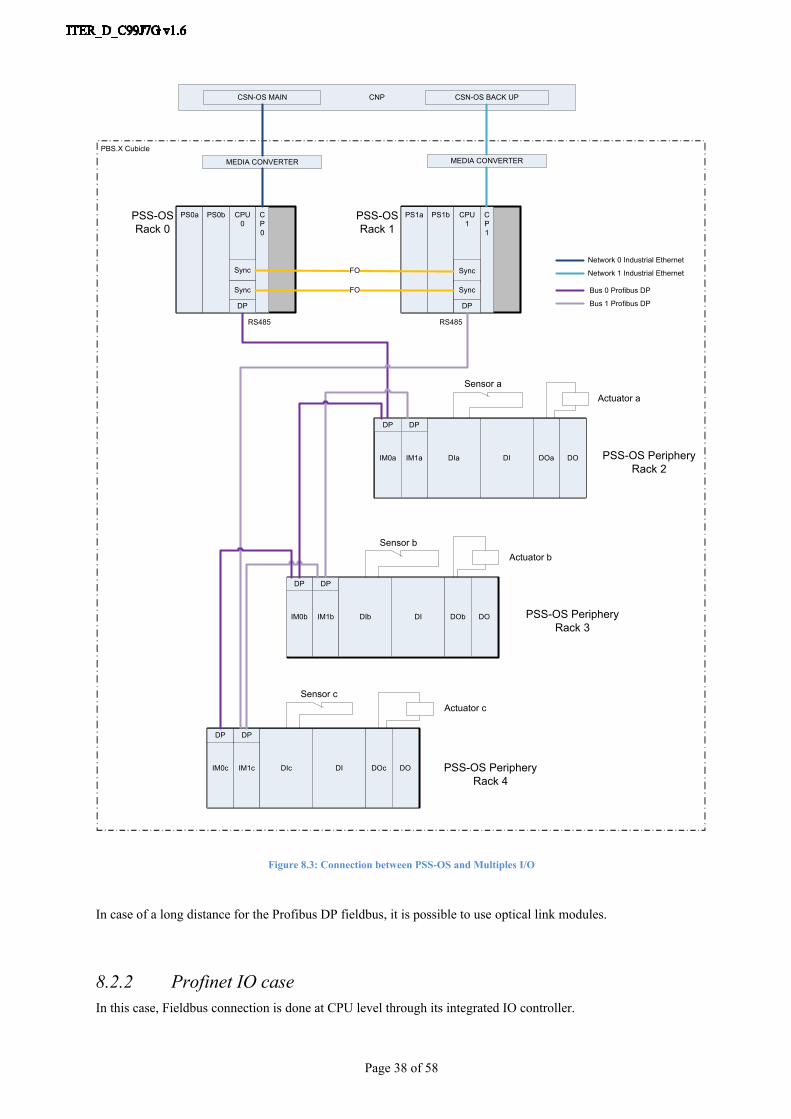
In the case of fault-tolerant PSS-OS architecture, the Profibus DP network shall be redundant: each redundant CPU is connected to all the peripheral racks using two interface modules (IM 153-2 HF) per rack as shown on the figure below:
Page 38 of 58
PS0a PS0b CPU0
CP0
Sync
Sync
PS1a PS1b CPU1
CP1
Sync
Sync
FO
FO
PSS-OSRack 0
PSS-OSRack 1
IM0a IM1a DIa DI DOa DO
IM0b DI DOb DOIM1b
DP DP
DP DP
DP DP
MEDIA CONVERTER MEDIA CONVERTERPBS.X Cubicle
Sensor a
DIb
Sensor b
Actuator a
Actuator b
IM0c DI DOc DOIM1c
DP DP
DIc
Sensor cActuator c
PSS-OS PeripheryRack 2
PSS-OS PeripheryRack 3
PSS-OS PeripheryRack 4
Bus 0 Profibus DP
Bus 1 Profibus DP
Network 1 Industrial Ethernet
Network 0 Industrial Ethernet
RS485 RS485
CNPCSN-OS MAIN CSN-OS BACK UP
Figure 8.3: Connection between PSS-OS and Multiples I/O
In case of a long distance for the Profibus DP fieldbus, it is possible to use optical link modules.
8.2.2 Profinet IO caseIn this case, Fieldbus connection is done at CPU level through its integrated IO controller.

Page 39 of 58
PBS.X Cubicle
CPU CPa
CPb
PSS-OSRack 0
IM0a DIa DOa
MEDIA CONVERTER MEDIA CONVERTER
Sensor a
Actuator a
Actuator b
PSS-OS PeripheryRack 1
DIb
Sensor b
DOb
Bus 0 Profinet IO
Network 1 Industrial Ethernet
Network 0 Industrial Ethernet
CNPCSN-OS MAIN CSN-OS BACK UP
IO
IO
Figure 8.4: Connection between PSS-OS and an I/O
Implementation of fault-tolerant architecture is complex through a star topology or additional IO Controller. The standard Profinet IO network for multiples remote I/O case has a ring topology: each redundant CPU is connected to all the peripheral racks using one interface modules per rack as shown on the figure below.Note: The synchronization links between CPU allow the closure of the ring topology.

Page 40 of 58
PS0a PS0b CPU0
CP0
Sync
Sync
PS1a PS1b CPU1
CP1
Sync
Sync
FO
FO
PSS-OSRack 0
PSS-OSRack 1
IM0a DIa DI DOa DO
IM0b DI DOb DO
MEDIA CONVERTER MEDIA CONVERTERPBS.X Cubicle
Sensor a
DIb
Sensor b
Actuator a
Actuator b
IM0c DI DOc DODIc
Sensor cActuator c
PSS-OS PeripheryRack 2
PSS-OS PeripheryRack 3
PSS-OS PeripheryRack 4
Bus 0 Profinet IO
Network 1 Industrial Ethernet
Network 0 Industrial Ethernet
CNPCSN-OS MAIN CSN-OS BACK UP
IO
IO
IO
IO IO
Figure 8.5: Connection between PSS-OS and Multiples I/O
Page 41 of 58
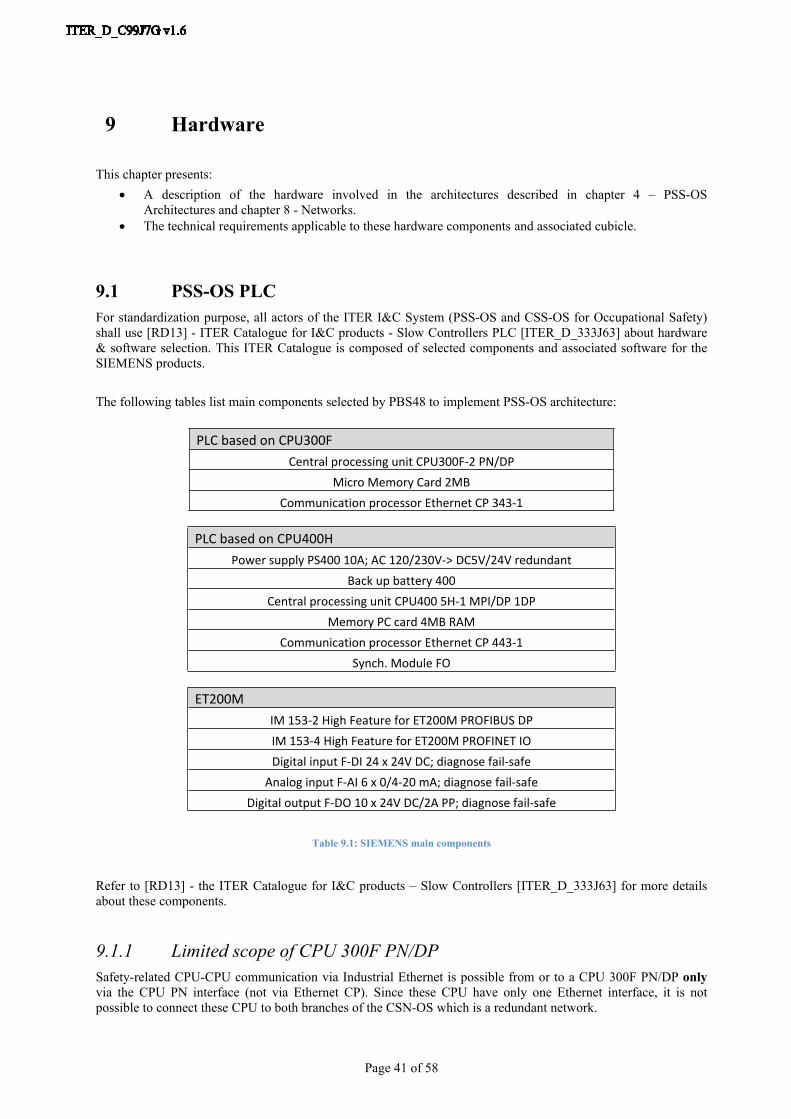
9 Hardware
This chapter presents: A description of the hardware involved in the architectures described in chapter 4 – PSS-OS
Architectures and chapter 8 - Networks. The technical requirements applicable to these hardware components and associated cubicle.
9.1 PSS-OS PLCFor standardization purpose, all actors of the ITER I&C System (PSS-OS and CSS-OS for Occupational Safety) shall use [RD13] - ITER Catalogue for I&C products - Slow Controllers PLC [ITER_D_333J63] about hardware & software selection. This ITER Catalogue is composed of selected components and associated software for the SIEMENS products.
The following tables list main components selected by PBS48 to implement PSS-OS architecture:
PLC based on CPU300FCentral processing unit CPU300F-2 PN/DP
Micro Memory Card 2MBCommunication processor Ethernet CP 343-1
PLC based on CPU400HPower supply PS400 10A; AC 120/230V-> DC5V/24V redundant
Back up battery 400Central processing unit CPU400 5H-1 MPI/DP 1DP
Memory PC card 4MB RAMCommunication processor Ethernet CP 443-1
Synch. Module FO
ET200MIM 153-2 High Feature for ET200M PROFIBUS DPIM 153-4 High Feature for ET200M PROFINET IODigital input F-DI 24 x 24V DC; diagnose fail-safe
Analog input F-AI 6 x 0/4-20 mA; diagnose fail-safeDigital output F-DO 10 x 24V DC/2A PP; diagnose fail-safe
Table 9.1: SIEMENS main components
Refer to [RD13] - the ITER Catalogue for I&C products – Slow Controllers [ITER_D_333J63] for more details about these components.
9.1.1 Limited scope of CPU 300F PN/DPSafety-related CPU-CPU communication via Industrial Ethernet is possible from or to a CPU 300F PN/DP only via the CPU PN interface (not via Ethernet CP). Since these CPU have only one Ethernet interface, it is not possible to connect these CPU to both branches of the CSN-OS which is a redundant network.

Page 42 of 58
Consequently, the CPU 300F PN/DP are allowed for PSS-OS architecture only if no safety-related communication is required between the PSS-OS and the CSS-OS PLC (case for which PSS-OS is not involved in any central function). So the interfaces between PSS-OS and CSS-OS PLC are safety-related communications between F/FH Systems only.
9.1.2 SIMATIC S7 Fail-safe Systems comparisonThe following tables list main criteria to take into account during hardware selection phase.
SIMATIC S7 Distributed Safety System
SIMATIC S7 F/FH System
Fault-tolerant feature No Yes
Power supply redundancy feature External management only Yes
Connection of fail-safe I/O Centrally or distributed Distributed only
Modification of safety program in the F-CPU in RUN mode
Possible in deactivated safety mode. Transition to safety mode is only possible by
switching the F-CPU to STOP mode.
Possible in deactivated safety mode or via Safety Data Write. Change of operating
mode of F-CPU is not required for transition to safety mode.
Fault reactions in the safety program
Passivation of channels or F-I/O + F-CPU in STOP mode
Passivation of channels of F-I/O + F-STOP instead of STOP of the F-CPU i.e. optional shutdown of all F-shutdown groups or only of the F-shutdown group in which fault was
detected.
Safety related communication via Industrial Ethernet
Only via the CPU PN interface Via CPU PN interface or via Ethernet CP
Number of S7 connections resources
315F-2PN/DP: 16 connections 414-5H PN/DP: 64 connections
Table 9.2: SIMATIC S7 Fail-safe systems comparison
9.2 PSS-OS cubiclesThe components belonging to the PSS-OS are hosted in dedicated PSS-OS cubicles which shall not be shared with conventional control, interlock or nuclear safety systems.For maintenance purposes, cubicles should be installed as far as possible from the sources of disturbances of Tokamak Building (building B11) and in areas which are accessible during plasma operation.
The main applicable rules are:
The PSS-OS cubicles (floor standing or wall mounted type) must be chosen from [RD12] - ITER catalogue for I&C products – Cubicles [ITER_D_35LXVZ].
The space reservation and allocation of the components inside of the PSS-OS cubicle must be compliant with [RD15] - I&C Cubicle Internal Configuration [ITER_D_4H5DW6]. All electrical components (power supplies, circuit breakers…) have to be fully accessible and easily removable in order to be replaced even if the cubicle is still powered (use of DIN rail is preferred).
The naming convention defined in [RD23] - ITER Numbering System for Components and Parts [ITER_D_28QDBS] is applicable for the occupational safety components. The static signage component must be compliant with [RD28] – ITER Site Signage & Graphics Standard [ITER_D_4AlJEU].
The handling and installation of the PSS-OS cubicles must be compliant with [RD15] - I&C Cubicle Internal Configuration [ITER_D_4H5DW6].
Page 43 of 58
The requirements for Earthing and electromagnetic compatibility and the cable entries (on top or on bottom) described in [RD16] - EDH Part 1: Introduction [ITER_D_2F7HD2], in [RD18] - EDH Part 4: Electromagnetic Compatibility (EMC) [ITER_D_4B523E] and in [RD22] – EDH Part 5: Earthing and Lightning Protection [ITER_D_4B7ZDG] are applicable to the PSS-OS cubicles.
The specific requirements for Siemens hardware installation (e.g. cable section for backplane connexion, etc.) defined in [RD24] – SIMATIC S7-300 CPU 31xC and 31x Installation, [RD25] – SIMATIC Automation system S7-400 Hardware and Installation, [RD26] – SIMATIC Distributed device ET200M and [RD27] – SIMATIC Distributed device Fail-safe signal modules should be taken into account and respected.
The recommendations of the suppliers (Sarel, Siemens…) for hardware installation shall be followed.
9.2.1 Environmental conditionsITER plant systems will contain a large quantity of electronic, electrical, and electromechanical (EEE) components. Some of them will be, by necessity, located in the radiation and magnetic fields in the TOKAMAK Complex (or near) and can be negatively affected by these environmental conditions.
This is the reason why ITER plant electronic, electrical and electro-mechanical systems, and among them the PSS-OS, must comply with the requirements for operating within or near the TOKAMAK Complex.
Refer to [RD2] - ITER Policy on EEE in the Tokamak Complex [ITER_D_6ZX6S3] and [RD3] - Guidance for EEE in Tokamak Complex [ITER_D_7NPFMA] for more details.
Note: Due to high magnetic fields and radiation levels, no safety I&C Logic control cubicles must be installed inside the Tokamak Building (B11).
9.2.2 Cubicle MonitoringAll I&C cubicles procured as components of a plant system I&C shall include a monitoring system.
For Occupational Safety systems, the functional requirements are similar to functional requirements for conventional cubicle monitoring described in [RD14] - I&C cubicle monitoring system – Functional specification [ITER_D_7A45LE] and in section 7 of [RD15] - I&C cubicle internal configuration [ITER_D_4H5DW6].
The PSS-OS Cubicle Monitoring System shall monitor or control the following parameters of a cubicle:
- Cubicle front door status (open/close),- Cubicle rear door status (open/close),- Cooling system status (run/stop),- Temperature value inside the cubicle in Celsius to control the operation of the cubicle cooling system
(through HH threshold).
Two options are proposed for the cubicle monitoring controller:- The main and recommended option is to use the PSS-OS PLC and spare channels of fail-safe signal
modules to implement the cubicle monitoring functions.- Another option similar to ‘conventional control’ solution is to use one SIMATIC CPU 1214C per
cubicle.
The second option is considered in order to propose a cost-reduced option in case of no I/O modules are available inside or near to a cubicle which shall be monitored.
The document [RD32] - Guidelines for the PSS-OS Configuration [ITER_D_Q6KVXS] provides recommendations about the PSS-OS software implementation of the Cubicle Monitoring system (first option). The document [RD33] – Occupational Safety Cubicle Monitoring based on S7-1200 [ITER_D_DZJ4ZT] provides

Page 44 of 58
information (implementation and integration purposes) about the Occupational Safety Cubicle Monitoring System solution based on SIMATIC S7-1200 models (second option).
The following table lists controller signals and main associated data, related to Cubicle Monitoring System.
Description Signal Name Signal Type & Range Engineering value Range
Front Door Close Status PPPPPP-CU-NNNN:ZC1-CCC DI [0-24V] 0: Not Closed ; 1: Closed
Rear Door Close Status PPPPPP-CU-NNNN:ZC2-CCC DI [0-24V] 0: Not Closed ; 1: Closed
Temperature Value PPPPPP-CU-NNNN:TT1-CCC AI [4-20mA] 0°C - 100°C
Cooling System (e.g. fan) Control PPPPPP-CU-NNNN:FAN-CCC DO [0-24V] 0: Off ; 1: On
Red Fault Light Control PPPPPP-CU-NNNN:FAULT-CCC DO [0-24V] 0: Light Off ; 1: Light On
Table 9.3: Cubicle Monitoring System – List of Controller Signals
9.3 PSS-OS SwitchAccording to number of clients (PLC or CPU) to connect to the Central Safety Networks, two options have to be considered for hardware implementation. In most cases, connection between Plant System and Central Safety System will be realize via media converters (because only one client to connect to each CSN-OS). However in case of several clients (Cubicle Monitoring PLC for example), a switch shall be used.Note: The Cubicle Monitoring System can be connected to any branch of the CSN-OS. This connection will be defined in IS48-PSS. PBS48 will lead the definition of the IP address in order to keep it unique in the CSN-OS network and provide the Subnet mask for the configuration of this controller. Like for the PSS-OS PLC, the cubicle integrator shall provide the connection up to the Central I&C Network Panel (CNP).
The characteristics required are at least:- COTS component,- DIN rail mounting,- Manageable from remote,- Compliant with environmental conditions like operating humidity and operating temperature,- power supply with redundancy management,- Interface ports:
o Single mode fibre-optic ports: SC socket,o Twisted pair ports: RJ45 socket.
- Security features:o SSH v2 and SSL encryption,o 802.1x with port security to authenticate the port and manage network access for all MAC
addresses,o Port security based on MAC address,o SNMP v3 authentication and 56-bit encryption,
- Network Management features:o VLAN (802.1Q) standard,o Class of service & Quality of service (802.1P) support,o CLI management interfaces,o Compliant with latest version of SNMP,o Remote management possibilities to enable/disable ports remotely (SNMP),o Embedded support for Web based management using standard web browser,
- Operating system features:o Simple plug & play operation-automatic learning, negotiation and cross over detection,o Port configuration, status, statistics, mirroring, local and remote security,o NTP time synchronization.
This switch shall be compliant with the infrastructure & components characteristics of the Central Safety Networks for Occupational Safety.
Page 45 of 58
9.4 PSS-OS signal cabling When signal redundancy is required, the redundant cables should be kept as separate as possible but they can be routed through the same cable tray.
It is recommended that signals are connected to the I/O modules through terminal blocks. It is advisable to install an external protective circuit in order to provide sufficient surge strength to an ET200M with fail-safe signal modules. It is recommended that the Marshaling Terminal Assembly referenced in [RD13] - Catalogue for I&C products – Slow controllers PLC [ITER_D_333J63] is used. It is possible to use equipments recommended in [RD15] – I&C Cubicle Internal Configuration [ITER_D_4H5DW6] if these equipment are approved up to SIL3 according to [AS1] - IEC 61508 and enable the reliability requirements to be fulfilled.
The Cubicle Monitoring system shall have dedicated terminal blocks.
The cables must be chosen from the [RD16] - IO Cable Catalogue [ITER_D_355QX2].The PSS-OS signal cabling must be compliant with:
[RD1] - Plant Control Design Handbook [ITER_D_27LH2V], [RD15] - I&C Cubicle Internal Configuration [ITER_D_4H5DW6], [RD19] - IO Cabling rules [ITER_D_335VF9], [RD23] - ITER Numbering System for Components and Parts [ITER_D_28QDBS], [RD26] – SIMATIC Distributed I/O device ET200M, [RD27] – SIMATIC Distributed I/O device Fail-safe signals modules, [RD28] – ITER Site Signage & Graphics Standard [ITER_D_4ALJEU].
9.5 PSS-OS powering
9.5.1 Conceptual principlesThe powering of PSS-OS cubicles must be compliant with the Electrical Design Handbook, in particular [RD20] - EDH Guide A: Electrical Installations for SSEN Client Systems [ITER_D_2EB9VT].
The following rules apply:- All PSS-OS cubicles and components must be redundantly powered,- The redundant powering cables must be kept as separate as possible minimizing the use of the same cable
tray,- Circuit breakers must at least allow the independent power on/off of each train, each architecture and its
periphery independently.- The power supplies must be monitored so that a failure of one power supply can be reported and repaired
in order to restore the redundant configuration in the minimum period of time.
The PSS-OS cubicles are powered by two independent sources: Class II-IP power supply: an uninterruptible with backup by battery set of 1 hour autonomy and by a
diesel generator available for 24 hours, Class IV-OL power supply: an alternative power supply in the event of class II-IP inverter failure or
fault in the class II-IP power feeder.
For powering all the recommended components, it is required to have the following voltages in the cubicles:• Class II-IP – 230VAC,• Class IV-OL – 230VAC,• Class II-IP – 24Vdc,• Class IV-OL – 24Vdc.
In most cases, the 24Vdc is generated locally by power supply modules powered by 230 Vac sources.

Page 46 of 58
9.5.2 CPU racks of PSS-OS architectures based on S7 Distributed SafetyFor the PSS-OS architectures based on S7 Distributed Safety fail-safe systems, it is not possible to integrate redundant power supplies directly in CPU rack. Two options are proposed in order to fulfil redundancy requirements:First option is to use two external non-redundant power supplies and one add-on module. The add-on module based on diodes disconnects the two parallel basic power devices. Failure of a single power supply no longer compromises the safe and uninterrupted supply of 24Vdc.
CPU300F
~
=
~
=
+ +
+ -
DB P
S II-P
230V
ac
DB P
S IV
OL 2
30Va
c
Redundant Power supply 24Vcc
Single Power supply 24Vcc from Class IV OL
Single Power supply 24Vcc from Class II IP
Power supply Class II-IP
Power supply Class IV OL
Figure 9.1: Option 1 for powering CPU rack for PSS-OS based on S7 Distributed Safety
The power supply equipment must be chosen from the [RD13] - ITER Catalogue for I&C products – Slow Controllers PLC [ITER_D_333J63].
Second option is to use two external redundant power supplies (equipped with internal power diodes for parallel operation). One advantage of this type of power system is reduction of components quantitative through the integration of diodes.

Page 47 of 58
CPU300F
~
=
~
=
Redundant Power supply 24Vcc
Single Power supply 24Vcc from Class IV OL
Single Power supply 24Vcc from Class II IP
Power supply Class II-IP
Power supply Class IV OL
DB P
S II-P
230V
ac
DB P
S IV
OL 2
30Va
c
Figure 9.2: Option 2 for powering CPU rack for PSS-OS based on Distributed Safety
Selected redundant power supply must be compliant with SIEMENS requirements. Refer to [RD24] – SIMATIC S7-300 CPU 31xC and CPU 31x Installation (section 4.10) for more details.
9.5.3 CPU racks of PSS-OS architecture based on S7 F/FH SystemEach S7-400 CPU rack shall be powered by two redundant power supply modules (PS 407 AC 120/230V DC 5V / 10A for redundant use). The first power supply module shall be powered by a class II-IP power supply and the second one by a class IV-OL power supply. Each power supply module shall have two backup batteries in its battery compartment (Battery Lithium AA 3.6 V / 2.3 Ah).
Figure 9.3: Powering CPU rack for PSS-OS based on S7 F/FH System
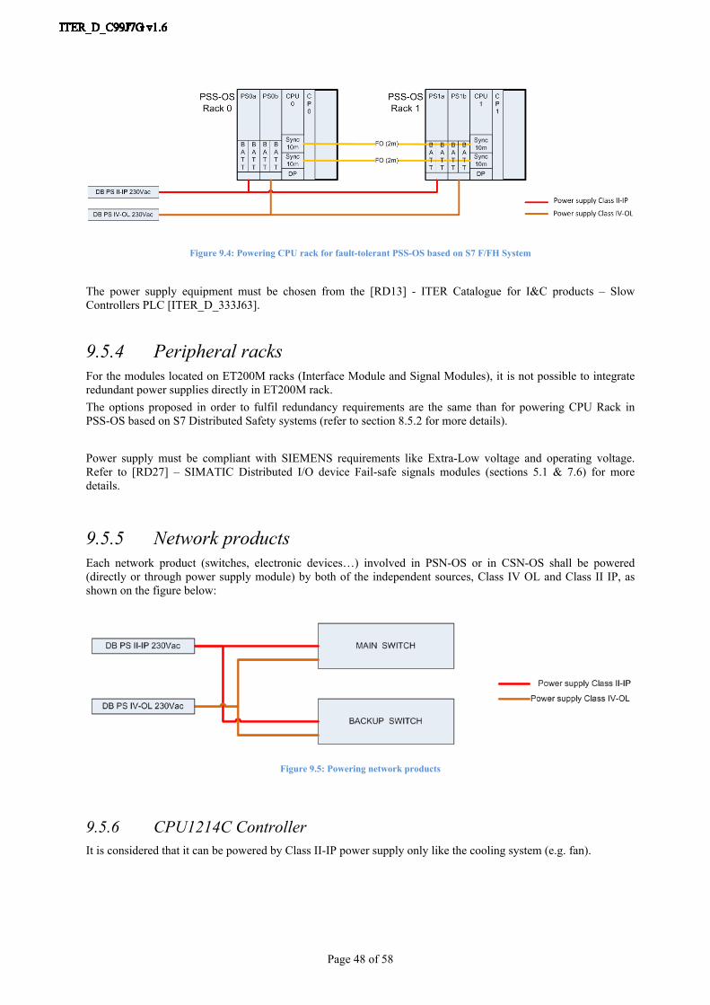
Page 48 of 58
Figure 9.4: Powering CPU rack for fault-tolerant PSS-OS based on S7 F/FH System
The power supply equipment must be chosen from the [RD13] - ITER Catalogue for I&C products – Slow Controllers PLC [ITER_D_333J63].
9.5.4 Peripheral racksFor the modules located on ET200M racks (Interface Module and Signal Modules), it is not possible to integrate redundant power supplies directly in ET200M rack. The options proposed in order to fulfil redundancy requirements are the same than for powering CPU Rack in PSS-OS based on S7 Distributed Safety systems (refer to section 8.5.2 for more details).
Power supply must be compliant with SIEMENS requirements like Extra-Low voltage and operating voltage. Refer to [RD27] – SIMATIC Distributed I/O device Fail-safe signals modules (sections 5.1 & 7.6) for more details.
9.5.5 Network productsEach network product (switches, electronic devices…) involved in PSN-OS or in CSN-OS shall be powered (directly or through power supply module) by both of the independent sources, Class IV OL and Class II IP, as shown on the figure below:
Figure 9.5: Powering network products
9.5.6 CPU1214C ControllerIt is considered that it can be powered by Class II-IP power supply only like the cooling system (e.g. fan).
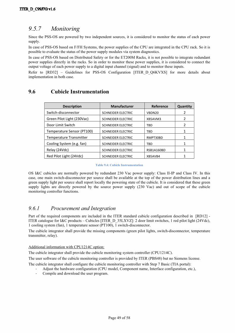
Page 49 of 58
9.5.7 MonitoringSince the PSS-OS are powered by two independent sources, it is considered to monitor the status of each power supply.In case of PSS-OS based on F/FH Systems, the power supplies of the CPU are integrated in the CPU rack. So it is possible to evaluate the status of the power supply modules via system diagnostics.In case of PSS-OS based on Distributed Safety or for the ET200M Racks, it is not possible to integrate redundant power supplies directly in the racks. So in order to monitor these power supplies, it is considered to connect the output voltage of each power supply to a digital input channel (signal) and to monitor these inputs.Refer to [RD32] – Guidelines for PSS-OS Configuration [ITER_D_Q6KVXS] for more details about implementation in both case.
9.6 Cubicle Instrumentation
Description Manufacturer Reference QuantitySwitch-disconnector SCHNEIDER ELECTRIC VBDN20 2Green Pilot Light (230Vac) SCHNEIDER ELECTRIC XB5AVM3 2Door Limit Switch SCHNEIDER ELECTRIC TBD 2Temperature Sensor (PT100) SCHNEIDER ELECTRIC TBD 1Temperature Transmitter SCHNEIDER ELECTRIC RMPT30BD 1Cooling System (e.g. fan) SCHNEIDER ELECTRIC TBD 1Relay (24Vdc) SCHNEIDER ELECTRIC RSB1A160BD 1Red Pilot Light (24Vdc) SCHNEIDER ELECTRIC XB5AVB4 1
Table 9.4: Cubicle Instrumentation
OS I&C cubicles are normally powered by redundant 230 Vac power supply: Class II-IP and Class IV. In this case, one main switch-disconnector per source shall be available at the top of the power distribution lines and a green supply light per source shall report locally the powering state of the cubicle. It is considered that these green supply lights are directly powered by the source power supply (230 Vac) and out of scope of the cubicle monitoring controller functions.
9.6.1 Procurement and IntegrationPart of the required components are included in the ITER standard cubicle configuration described in [RD12] - ITER catalogue for I&C products – Cubicles [ITER_D_35LXVZ]: 2 door limit switches, 1 red pilot light (24Vdc), 1 cooling system (fan), 1 temperature sensor (PT100), 1 switch-disconnector.The cubicle integrator shall provide the missing components (green pilot lights, switch-disconnector, temperature transmitter, relay).
Additional information with CPU1214C option:The cubicle integrator shall provide the cubicle monitoring system controller (CPU1214C).The user software of the cubicle monitoring controller is provided by ITER (PBS48) but no Siemens license.The cubicle integrator shall configure the cubicle monitoring controller with Step 7 Basic (TIA portal):
- Adjust the hardware configuration (CPU model, Component name, Interface configuration, etc.),- Compile and download the user program.
Page 50 of 58
10 Software tools
As described in chapter 4 – PSS-OS architectures, several architectures are proposed for the design of the PSS-OS. These architectures are based on two ranges of Siemens S7 Fail-safe systems able to reach SIL3 in accordance with IEC 61508: Distributed Safety and F/FH Systems.
To configure and program S7 F/FH systems, it is necessary to use:- Step 7 which is the basic software for configuring and programming Siemens PLCs,- Continuous Function Chart which is an optional software/language for programming the Siemens S7-400
family of PLCs and which is based on graphical connection of function blocks in a data flow arrangement,
- S7 F Systems which is an optional package for configuring and programming Siemens S7 F/FH Systems and providing an F-Library containing F-Blocks that are used to generate the safety program.
To configure and program S7 Distributed Safety systems, it is necessary to use:- Step 7 which is the basic software for configuring and programming Siemens PLCs,- S7 Distributed Safety which is an optional package for configuring and programming Siemens S7
Distributed Safety systems and providing an F-Library containing F-Blocks that are used to generate the safety program. The programming languages for the safety program are F-LAD or F-FBD which are similar to standard LAD and FBD programming languages.
The document [RD13] - ITER catalogue for I&C products – Slow controllers PLC [ITER_D_333J63] provides more details about software packages, Operating System compatibility and versions compatibility.
The document [RD32] - Guidelines for PSS-OS Configuration [ITER_D_Q6KVXS] provides more information about the programming environment.
Page 51 of 58
11 Software Interfaces with the CSS-OS
As explained in chapter 8 -Networks, the interfaces between the PSS-OS and the CSS-OS take place via the CSN-OS and concern the following functions:
- Interface with the CSS-OS Safety PLC for the coordination of the plant systems involved in the implementation of central occupational safety functions
- Interfaces with the CSS-OS SCADA servers for the supervisory control and data acquisition of the PSS-OS information
- Interfaces with the CSS-OS NTP servers for the Occupational Safety systems time synchronization- Interfaces with the CSS-OS Engineering workstation for specific maintenance features like modification
of PSS-OS PLC configuration.
11.1 Interface with the CSS-OS safety PLC
11.1.1Functional concepts
The variables to be exchanged are the variables directly participating in the implementation of the central occupational safety functions (event and action transmission as defined in section 2.3.2 Central Automatic function and in section 2.3.3 Central Manual function).
11.1.2Method
Safety-related communication between CPU is based on standard protocol but implements an additional safety shell on top.Safety-related communication is based on S7 connections. Considering the redundancy of the CSN-OS (refer to chapter 8 - Networks) and the range of CPU proposed for the PSS-OS involved in the implementation of central occupational safety functions (refer to section 9.1 – PSS-OS PLC), it is considered that the safety-related communication between the PSS-OS PLC and the CSS-OS PLC is based on S7 fault-tolerant connections.For sending and/or receiving data in a fail-safe manner via S7 (fault-tolerant) connections, some fail-safe blocks are available in the S7 F systems Library (F-User Blocks\COM_FUNC):
- F_SENDBO (FB370) for sending 20 data elements of data type F_BOOL in a fail-safe manner to another F-CPU
- F_RCVBO (FB371) for receiving 20 data elements of data type F_BOOL in a fail-safe manner from another F-CPU
- F_SENDR (FB372) for sending 20 data elements of data type F_REAL in a fail-safe manner to another F-CPU
- F_RCVR (FB373) for receiving 20 data elements of data type F_REAL in a fail-safe manner from another F-CPU
- F_SDS_BO (FB352) for sending 32 data elements of data type F_BOOL in a fail-safe manner to another F-CPU
- F_RDS_BO (FB353) for receiving 32 data elements of data type F_BOOL in a fail-safe manner from another F-CPU
Theses blocks shall be called by users in the relevant safety program of the CPU: the F-Block for sending data elements is positioned in the safety program of the sending CPU and the associated F-Block for receiving data elements is positioned in the safety program of the receiving CPU.The document [RD32] - Guidelines for the PSS-OS Configuration [ITER_D_Q6KVXS] provides recommendations about the implementation of this interface.
Page 52 of 58
11.2 Interface with the CSS-OS SCADA servers
11.2.1Functional concepts
The data to be exchanged are all the data required to be displayed or operated from the CSS-OS Operator terminals or to be logged and a few data to manage the interface between the CSS-OS SCADA servers and the Occupational Safety PLC.A few data are considered to be exchanged from the CSS-OS SCADA servers to the Occupational Safety PLC:
- The main type of operator commands operated from the CSS-OS Operator terminals are the “reset”. Indeed, the safety system shall be designed in such a way that once it has placed the process in a safe state, it shall remain in the safe state until a reset has been initiated. The reset shall be ignored as long as the hazard (represented by a set of conditions and events) has not been eliminated.
- Another type of operator commands operated from the CSS-OS Operator terminals is considered: the “overrides”. Safety functions are put in place to protect ITER from safety hazards, so overrides should be avoided as much as possible. However, it may be required to be able to disable inputs from a safety-related system or functions for maintenance activities, to avoid trip actions caused by spurious signals or logic tests. The document [RD32] - Guidelines for the PSS-OS Configuration [ITER_D_Q6KVXS] provides more detailed information about this topic.
- It is also considered to exchange a few data for the interface management and system diagnostics (e.g. Alive Counter, TSPP Active Connection, etc.).
The largest part of the data to be exchanged between the CSS-OS SCADA servers and the Occupational Safety PLC are in the other direction: from the Occupational Safety PLC to CSS-OS SCADA servers:
- It is considered that the following information will be part of the operator interface (screen display, alarm and/or logging):
o Status of Input / Output signalso Safety physical parameter threshold exceededo Safety function activationo Overrides statuso Results of Sensor/Function/Actuator diagnosticso Results of System Diagnosticso Cubicle Monitoring information
- It is also considered to exchange a few data for the interface management and system diagnostics calculated by the CSS-OS SCADA servers (e.g. Alive Counter, PLC Date/Time, etc.).
The document [RD32] - Guidelines for the PSS-OS Configuration of the PSS-OS [ITER_D_Q6KVXS] provides general recommendations about this functional interface.
11.2.2Method
For general monitoring, it is considered to implement a sending/polling method with the CSS-OS SCADA Server driver master in the communication as usual for a SCADA system.For critical archiving, it is considered to implement a time-stamped pushed method with the Occupational Safety PLC generating the time-stamps, managing a local buffer (in order to be able to retrieve events detected by the Occupational Safety PLC during a short loss of communication between the CSS-OS SCADA Servers and the Occupational Safety PLC) and sending its records to the CSS-OS SCADA servers.It is considered that the CSS-OS provides two SCADA servers both connected to both branches of the CSN-OS, so each method use four S7 connections resources.The document [RD32] - Guidelines for the PSS-OS Configuration of the PSS-OS [ITER_D_Q6KVXS] provides recommendations about the definition of information to push with original time-stamps, the implementation of the original time-stamping with the local buffer and about the implementation of the interface.
Page 53 of 58
11.3 Interface with the CSS-OS NTP servers
The Occupational Safety systems shall be synchronized with a time reference managed by the CSS-OS. It is considered that the CSS-OS provides one or two NTP servers both connected to both branches of the CSN-OS.The Communication Processors (CP) manage the interfaces with the CSN-OS and the NTP synchronization and forward the time of day to the CPU.Refer to [RD32] - Guidelines for the PSS-OS Configuration of the PSS-OS [ITER_D_Q6KVXS] for recommendations about the configuration of the NTP synchronization in the PSS-OS PLC.
11.4 Interface with the CSS-OS Engineering Workstation
The CSS-OS provides an Engineering workstation in order to allow maintenance features requiring the proprietary controller software (e.g. detailed system diagnostics, configuration of the PLC, etc.) on Occupational Safety controllers from the Control Building (Building 71). It is considered that the CSS-OS Engineering Workstation is connected to both branches of the CSN-OS.The Occupational Safety systems shall allow these connections i.e. reserve PG communication connection and authorize access to the station.Refer to [RD32] - Guidelines for the PSS-OS Configuration of the PSS-OS [ITER_D_Q6KVXS] for recommendations about the configuration of the Access Protection.

Page 54 of 58
12 Testing and Acceptance tests
The testing and acceptance tests are important tasks and they are an integral part of the ITER model of integration. These tests are intended to check the conformity of the deliverables with the requirements specified by ITER.In the process defined by the ITER model of integration, two major acceptance tests are defined: FAT (Factory Acceptance Tests) carried out at the supplier’s premises during the manufacturing phase and the SAT (Site Acceptance Tests) covering the all plant systems installed on the site during the integration phase.
Pre-FAT FAT
Manufacturing Phase
Site Reception
Integration Phase
SAT
PCDH Scope
IEC 61511 Scope
Operation Phase
OperationIntegrated commissioning
Figure 12.1: Integration Milestones
Note: The Site Acceptance Tests represent limit of scope of PCDH.
12.1 FATThe Plant System I&C Factory Acceptance Test (FAT) are intended to check the conformity of the procured plant system to the approved design. All I&C components in the procurement shall be powered and tested during FAT.The unit for PS I&C FAT is the PSS-OS cubicle with its embedded hardware and software.
Before starting the FAT the supplier must carry out a pre-FAT to detect and solve the manufacturing issues.
Pre-requisite:Manufacturing documents have been approved.FAT procedure has been validated.
The scope of the FAT should be adjusted according to the procurement configuration and will cover the following areas:
Mechanical and electrical configuration of the PSS-OS cubicleso Visual inspection for compliance control according to manufacturer’s specification (mechanical
conformity, configuration, wiring, segregation, naming convention, warning signs…)o Electrical conformity with all components powered (Earthing, connections, voltage measures…)o Ventilation test
PLC’s hardware and softwareo Visual inspection for compliance control according to manufacturer’s specification
(configuration, tagging…)o Software version controlo Software downloading procedure controlo PLC security control through authentication and authorization procedure
Page 55 of 58
Plant system configurationo Failure test (power supply redundancy, CPU redundancy, fieldbus connection loss…) and
associated Hardware diagnostic testo Loop checking to control I/O allocation (physical and software) and electrical to engineering
value conversion through input simulation and output monitoring Plant system I&C functions and associated interfaces
o Functional test for compliance control according to I&C function specifications (including threshold and central command like reset and override)
o Alarm managemento Performance test (response time, CPU cycle time, memory load…)
Documentation
During the FAT, the interfaces to the plant (instrumentation and actuators) are disconnected and simulated by test equipment. Interfaces to the PBS48 OS Central Plant System are also simulated by appropriate tools. The environmental conditions are those of the supplier’s factory.
12.2 SATThe Site Acceptance Tests (SAT) is intended to check conformity with IO requirements of the plant system procurement first as a stand-alone. All I&C components in the procurement shall be powered and tested during SAT.The unit for PS I&C SAT is the PSS-OS cubicle with its embedded hardware and software.Plant System I&C SAT is first a repeat of FAT for each procurement involved in. In addition, the SAT will include a performance test of the whole plant system where possible.
The SAT will also be performed on what was not covered for any reason by the FAT.
Pre-requisite:SAT procedures have been validated.Issue sheets from FAT (anomaly or modification request) have been solved.The PSS-OS cubicles are installed at final place, fixed and connected to ITER Power supply with power off.The PSS-OS cubicles are inter-connected (fieldbus for example).The PSS-OS cubicles are connected to Plant System process with marshalling connectors open.The PSS-OS cubicles are not connected to Central I&C infrastructure.
The scope of the SAT should be adjusted according to the procurement configuration and will cover the following areas:
Mechanical and electrical configuration of the PSS-OS cubicleso Visual inspection o Partial electrical conformity with all components powered (voltage measures…)
PLC’s hardware and softwareo Visual inspection o Software version controlo Software downloadingo PLC security control through authentication and authorization procedure
Plant system configurationo Partial failure test (power supply redundancy, CPU redundancy, fieldbus connection loss…) and
associated Hardware diagnostic testo Complete loop checking
Interface tests (after central I&C infrastructure connection)o Interface test between PSS-OS PLC and CSS-OS SCADA (data exchange, life bit protocol)o Interface test between PSS-OS PLC and CSS-OS PLC (data exchange, life bit protocol) if
central I&C function implementationo Interface test with NTP server
Plant system I&C functions and associated interfaceso Functional test for compliance control according to I&C function specifications (including
central command like reset and override)o Alarm management

Page 56 of 58
o Performance test (response time, CPU cycle time, memory load…) Documentation

Page 57 of 58
13 Standards compliance and SIL assessment
This paragraph highlights requirements for assessment of each safety instrumented system, based on IEC 61511 standard (and complementary on IEC 61508 standard).
The plant system suppliers have to deliver a SIL certified system that meets the safety requirements as described in the IEC 61511. Among activities associated to the 3 permanent phases of IEC 61511 standard lifecycle, the functional safety assessment (part of phase 10) manages necessary activities to demonstrate that the functional safety objectives are met.
Functional safety assessment in the context of IEC 61508 and IEC 61511 implies performing independent reviews and audits at predefined stages of the safety lifecycle. “Independent” implies that personnel not involved in the design should perform the Functional Safety Assessment. Moreover, it is important to involve highly competent personnel with diverse competence in the assessment, in order to reveal possible weaknesses, systematic failures and omissions.In accordance with [RD7] - Usage of IEC 61511 [ITER_D_DMF2CW], refer to IEC 61508 Part 1 section 8.2 about the minimum level of independence of people who carrying out a functional safety assessment.
From IEC 61511 IEC standard Part 1 Section 5.2.6:“A procedure shall be defined and executed for a functional safety assessment in such a way that a judgment can be made as to the functional safety and safety integrity achieved by the safety instrumented system. The procedure shall require that an assessment team is appointed which includes the technical, application and operations expertise needed for the particular installation.”
“At least one functional safety assessment shall be undertaken. This functional safety assessment shall be carried out to make sure the hazards arising from a process and its associated equipment are properly controlled. As a minimum, one assessment shall be carried out prior to the identified hazards being present (i.e. stage 3).”

Page 58 of 58
Figure 13.1: IEC 61511 standard life-cycle
The main associated evaluations to be made are: Project documentation assessment, Development and product design assessment, Analysis and studies of operational Safety assessment
o Assessment of failure modes, effects and diagnostic analysis,o Assessment of probability of dangerous failure calculations,
Assessment of verification and validation activities.