g:to be issuedci660-ci-001 p2 layout1 (1) · geostudio 2007 software package produced by...
TRANSCRIPT

Tetra Tech 3031 West Ina Road, Tucson, AZ 85741
Tel 520.297.7723 Fax 520.297.7724 www.tetratech.com
Technical Memorandum
To: Craig Hunt, P.E., M3 Engineering and Technology
Cc: Jamie Joggerst (Tetra Tech)
From: Mike Thornbrue and David Krizek, P.E.
Doc #: 074/09-320841-5.3
Subject: Rosemont Copper BADCT Analysis for the Settling Basin Date: May 4, 2009 This technical memorandum supersedes any previous liner leakage estimates or facility descriptions for the Settling Basin (previously named the Primary Settling Basin) presented in the Aquifer Protection Permit (APP) application prepared for Rosemont Copper Company (Tetra Tech, 2009a).
This technical memorandum has been prepared to demonstrate the Best Available Demonstrated Control Technology (BADCT) that will be employed for the Settling Basin at the proposed Rosemont Copper Project (Project). This surface impoundment is a categorical APP facility pursuant to A.R.S. §49-241(B)(1).
Prescriptive BADCT has not been established for the type of facility such as the Settling Basin. The Settling Basin is designed for short-term storage of non-filtered tailings (i.e., traditional slurry tailings) resulting from potential upset conditions associated with the Tailings Filter Plant. This technical memorandum provides an evaluation of the proposed BADCT design and temporary storage conditions of the basin.
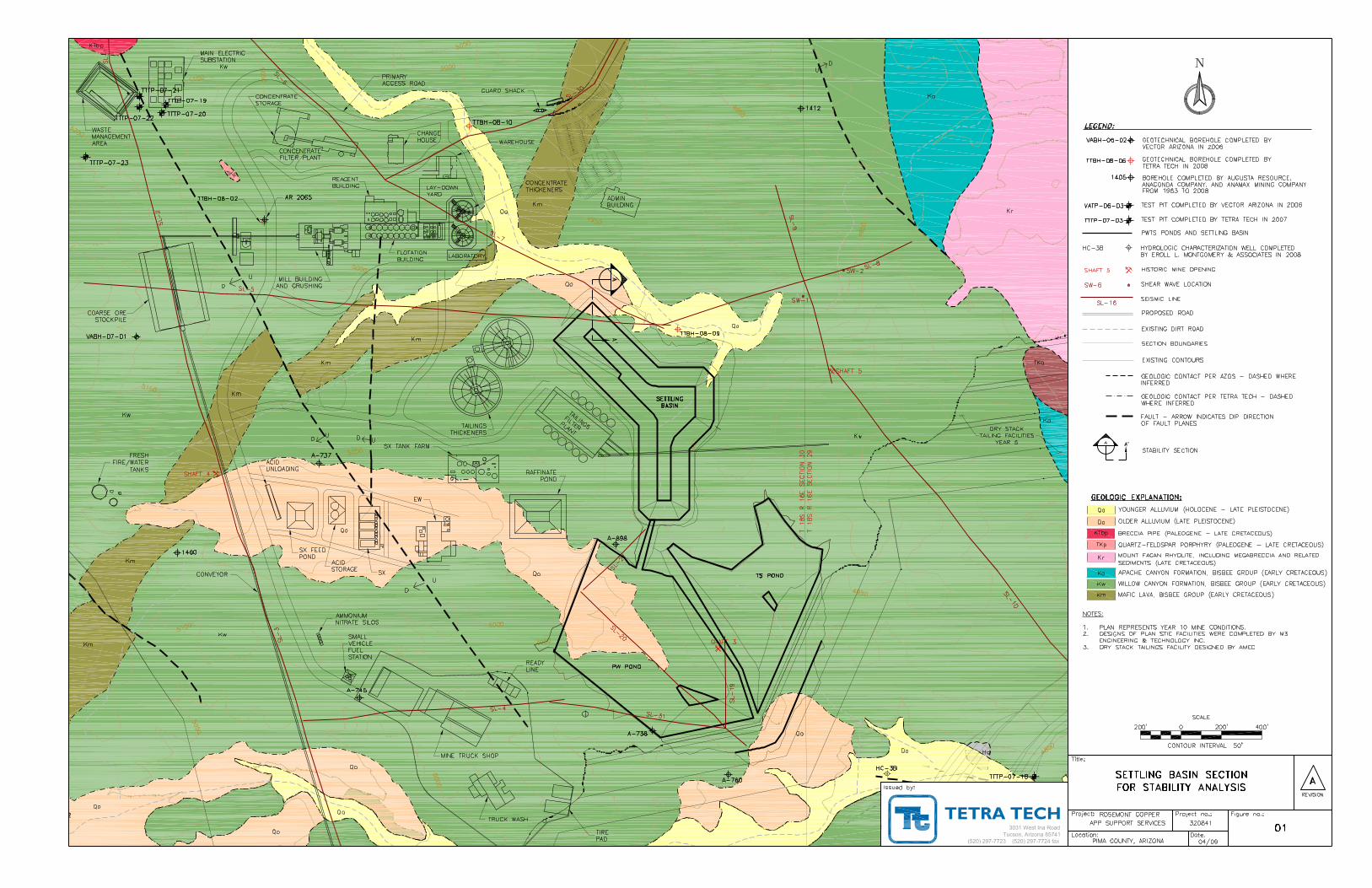
The Settling Basin will be located southeast of the Plant Site as shown on Figure 01 and will receive process upset materials comprised of non-filtered tailings. Tailings could be stored in the Settling Basin for a period not to exceed 90 days. Tailings decant water will be held in the Settling Basin until the conclusion of the upset condition or may overflow to the PW Pond portion of the PWTS Ponds Facility. Once proper operation is restored, the tailings solids in the Settling Basin will be re-slurried and pumped to the Tailings Thickener. It is anticipated that some tailings will remain in the basin following cleanout.
The Settling Basin is considered a settling/storage surface impoundment for the evaluation of BADCT. The Settling Basin will be lined with a Geosynthetic Clay Liner (GCL) with a protective gravel surface cover to facilitate the removal of tailings material.

2
1.0 Liner System The Settling Basin liner system will consist of the following (from bottom to top):
A minimum six (6) inch thick layer of properly compacted bedding soil (prepared subgrade);
A sodium bentonite GCL; and
A minimum 18 inch thick layer of 1.5 inch minus protective rock.
A cross section of the liner system for the Settling Basin is presented in Illustration 1.01.
Illustration 1.01 Primary Storage Basin Liner System
A leak detection and removal system (LCRS) is not proposed for the Settling Basin. A LCRS is not necessary because the engineering control achieved by the proposed design is adequate based on BADCT for a settling/storage surface impoundment containing non-filtered tailings. Additionally, the Settling Basin is designed for temporary storage which will minimize the opportunity for seepage.
3
2.0 Stability Analysis A stability analysis for the Settling Basin was performed using the Slope/W component of the GeoStudio 2007 software package produced by Geo–Slope International, Ltd. The analyzed section is based on the maximum height of the embankment which occurs in the northwest corner of the Settling Basin as shown on Figure 01, Section A. Sections 2.1 through 2.5 present the design criteria, methods and results of analyses performed.
2.1 Construction of Model Cross Section Both the upstream and downstream embankment slopes of the Settling Basin are proposed to be 2.5H:1V. The embankment is proposed to consist of locally excavated weathered bedrock from the Willow Canyon Formation. The inside face will also have a GCL overlain by minus 1.5 inch protective rock. As shown on Figure 01, the Settling Basin Embankment is mostly underlain by the Willow Canyon Formation. However, a small deposit of younger and older alluvium is present along the northeastern edge of the facility. The critical section of the Settling Basin embankment (i.e., the northwest corner) however, does encounter alluvium. Therefore, an alluvium layer was included in the model.
Local groundwater elevations have been recorded in well HC-3B, located approximately 1,700 feet from the Settling Basin. Groundwater level measurements in this well ranged from approximately 4,785 to 4,815 feet amsl (Errol L. Montgomery & Associates, 2009). The groundwater elevation is below the modeling boundaries such that the stability of the facility is not affected. Therefore, groundwater was not included in the model cross section.
2.2 Stability Requirements Design of the Settling Basin is governed by the requirements of the Arizona Department of Environmental Quality (ADEQ) as detailed in the Arizona Mining BADCT Guidance Manual and the Arizona Department of Water Resources (ADWR) as detailed in the Arizona Administrative Code (A.A.C.) Title 12, Chapter 15. Based on these requirements, the minimum stability criteria adopted for the Settling Basin embankment are presented in Table 2.01. Per BADCT requirements (ADEQ, 2004), site specific testing of material shear strength was performed. Additionally, a quality control testing program will be conducted during construction to determine grain size, plasticity index, moisture, density, etc., of the materials used to construct the Settling Basin embankment.
Table 2.01 Minimum Stability Requirements (with testing)
Analysis Condition Required Minimum Factor of Safety
Static 1.30 Pseudostatic 1.00
As documented in the Geologic Hazards Assessment (Tetra Tech, 2007a), the site seismicity was analyzed for two (2) levels of ground motion: the Maximum Probable Earthquake (MPE) and the Maximum Credible Earthquake (MCE). These values are 0.045g for the MPE and
4
0.326g for the MCE. In order to determine the appropriate design earthquake, all the applicable rules pertaining to the Settling Basin embankment were reviewed.
Based on A.A.C. Title 12, Chapter 15 Section 1206(A) Table 2, the Settling Basin was defined as an intermediate size dam since the embankment has a maximum height of 65 feet and a total storage capacity of 180 acre-feet.
A.A.C. R12-15-1206(B)(2)(a) defines a Very Low Hazard Dam Potential as:
“Failure or improper operation of a dam would be unlikely to result in loss of human life and would produce no lifeline losses and very low economic and intangible losses. Losses would be limited to the 100 year floodplain or property owned or controlled by the dam owner under long-term lease. The Department (ADWR) considers loss of life unlikely because there are no residences or overnight camp sites.”
In the unlikely event of a failure of the Settling Basin embankment, non-filtered tailings could flow into the Dry Stack Tailings Facilities or the PWTS Ponds. Therefore, any damage caused by the failure of the Settling Basin embankment would be limited to the Project site (i.e., property owned or controlled by the dam owner) and is unlikely to result in loss of human life. As per ADWR dam safety regulations, the Settling Basin embankment qualifies as an intermediate size, very low hazard dam.
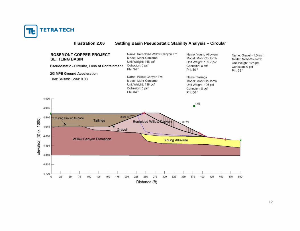
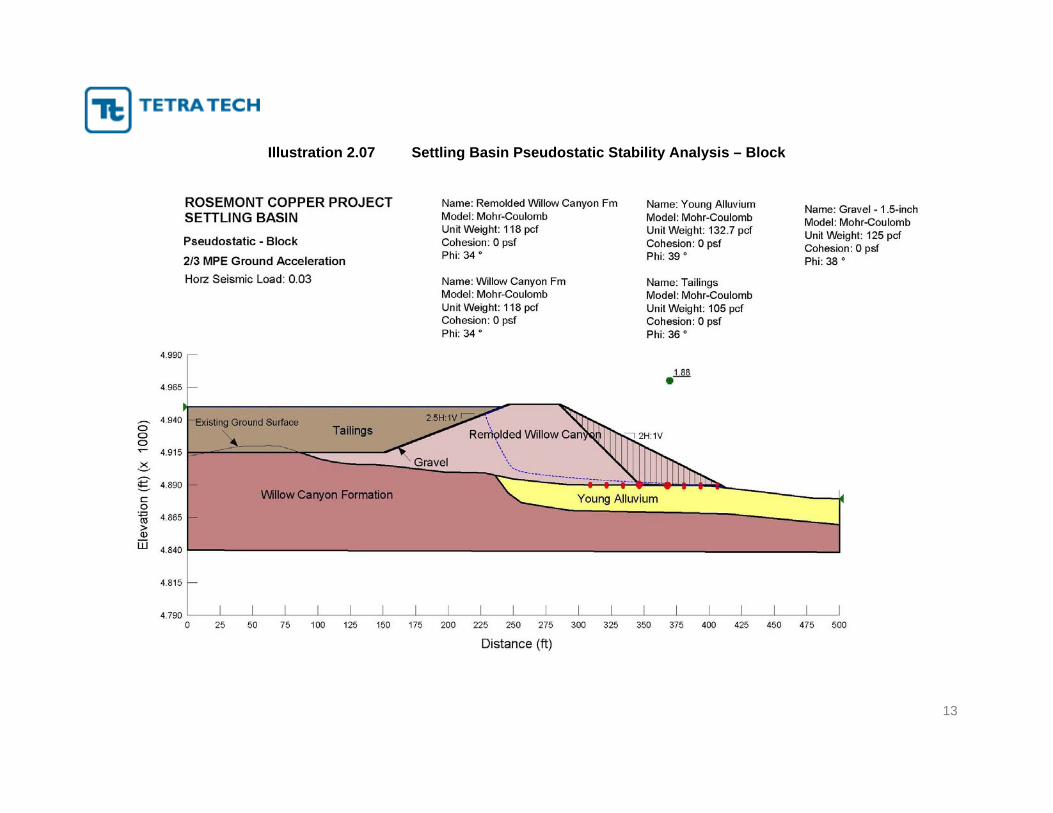
Since the Settling Basin embankment qualifies as an intermediate size, very low hazard dam, the MPE was utilized for pseudostatic analyses. To allow for damping and attenuation of the bedrock acceleration within the embankment, and to account for the rigid body pseudostatic model, the pseudo-static coefficient used in the model was a conservative estimate of horizontal ground motion equivalent to 2/3 of the MPE, or 0.03g.
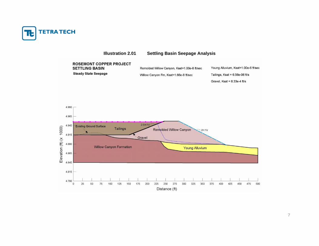
2.3 Modeling Methods As previously mentioned, the stability analysis was performed using the Slope/W component of GeoStudio 2007 software package. Since a GCL will be placed on the upstream side of the embankment, and the basin is designed for temporary storage of traditional non-filtered tailings, a steady-state seepage condition is not expected to develop in the embankment. However, for a conservative approach, a Seep/W model was performed, excluding the GCL. This modeling was performed for the purpose of inputting pore water pressures in the stability model. Hydraulic conductivity function curves used in the Seep/W analysis were adapted to site-specific conditions, including in-situ field permeability testing of subsurface materials. The Settling Basin was modeled using two (2) feet of freeboard below the embankment crest (water elevation 4,950 feet above mean sea level [amsl]).
Slope/W was used to conduct limiting equilibrium analyses using the general limit equilibrium (GLE) method, which satisfies both force and moment equilibrium. This program incorporates search routines to determine the critical, lowest factor of safety failure surface. Slope/W was used to conduct analyses of slope stability considering global (rotational) stability of the embankment and full-height failure (block) surfaces affecting the crest of the embankment on the downstream side of the embankment.
5
To evaluate the performance of the embankment under seismic loading, pseudostatic stability analyses were performed. The pseudostatic analyses subject the two-dimensional sliding mass to a horizontal acceleration equal to an earthquake coefficient multiplied by the acceleration of gravity.
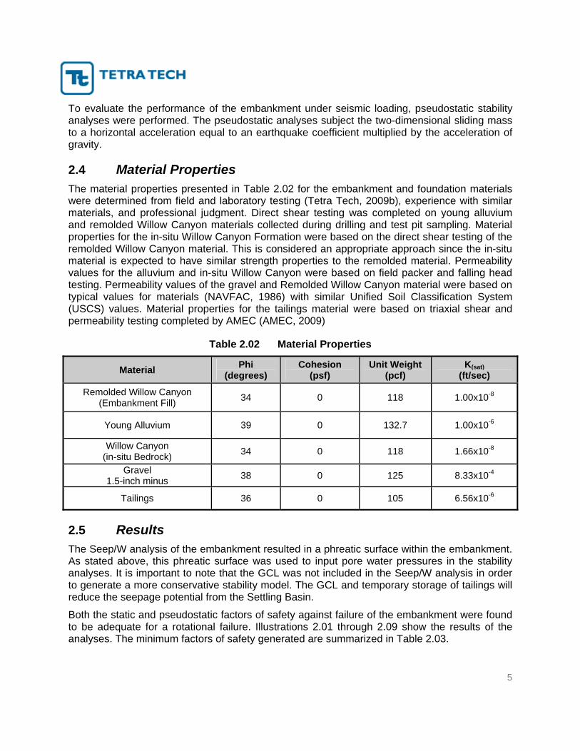
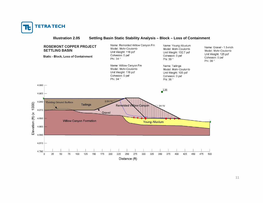
2.4 Material Properties The material properties presented in Table 2.02 for the embankment and foundation materials were determined from field and laboratory testing (Tetra Tech, 2009b), experience with similar materials, and professional judgment. Direct shear testing was completed on young alluvium and remolded Willow Canyon materials collected during drilling and test pit sampling. Material properties for the in-situ Willow Canyon Formation were based on the direct shear testing of the remolded Willow Canyon material. This is considered an appropriate approach since the in-situ material is expected to have similar strength properties to the remolded material. Permeability values for the alluvium and in-situ Willow Canyon were based on field packer and falling head testing. Permeability values of the gravel and Remolded Willow Canyon material were based on typical values for materials (NAVFAC, 1986) with similar Unified Soil Classification System (USCS) values. Material properties for the tailings material were based on triaxial shear and permeability testing completed by AMEC (AMEC, 2009)
Table 2.02 Material Properties
Material Phi (degrees)
Cohesion (psf)
Unit Weight (pcf)
K(sat) (ft/sec)
Remolded Willow Canyon (Embankment Fill) 34 0 118 1.00x10⁻⁸
Young Alluvium 39 0 132.7 1.00x10⁻⁶
Willow Canyon (in-situ Bedrock) 34 0 118 1.66x10⁻⁸
Gravel 1.5-inch minus 38 0 125 8.33x10⁻⁴
Tailings 36 0 105 6.56x10⁻⁶
2.5 Results The Seep/W analysis of the embankment resulted in a phreatic surface within the embankment. As stated above, this phreatic surface was used to input pore water pressures in the stability analyses. It is important to note that the GCL was not included in the Seep/W analysis in order to generate a more conservative stability model. The GCL and temporary storage of tailings will reduce the seepage potential from the Settling Basin.
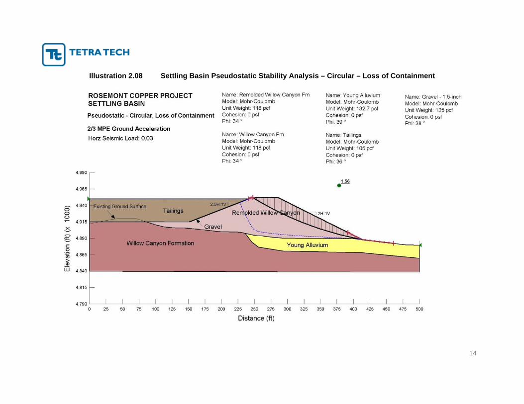
Both the static and pseudostatic factors of safety against failure of the embankment were found to be adequate for a rotational failure. Illustrations 2.01 through 2.09 show the results of the analyses. The minimum factors of safety generated are summarized in Table 2.03.

6
Table 2.03 Results of Slope Stability Analyses for the Settling Basin
Safety Factor Scenario Static Pseudostatic (MPE)
Global Failure, Circular 1.39 1.29 Global Failure, Block 2.00 1.88
Loss of Containment, Circular 1.69 1.56 Loss of Containment, Block 2.35 2.19
Based on these results, the static and pseudo-static factors of safety against failure of the Settling Basin embankment are adequate under normal operating conditions.
7
Illustration 2.01 Settling Basin Seepage Analysis

8
Illustration 2.02 Settling Basin Static Stability Analysis - Circular

9
Illustration 2.03 Settling Basin Static Stability Analysis - Block

10
Illustration 2.04 Settling Basin Static Stability Analysis – Circular – Loss of Containment
11
Illustration 2.05 Settling Basin Static Stability Analysis – Block – Loss of Containment
12
Illustration 2.06 Settling Basin Pseudostatic Stability Analysis – Circular
13
Illustration 2.07 Settling Basin Pseudostatic Stability Analysis – Block
14
Illustration 2.08 Settling Basin Pseudostatic Stability Analysis – Circular – Loss of Containment

15
Illustration 2.09 Settling Basin Pseudostatic Stability Analysis – Block – Loss of Containment

16
3.0 Evaluation of BADCT Alternatives Three (3) alternative lining systems were evaluated to determine the appropriate BADCT for the Settling Basin. All three (3) alternatives assumed a prepared subgrade compacted to 95% of maximum dry density (ASTM 698). The lining systems included:
A 12 inch thick concrete liner;
A GCL with 18 inches of protective rock; and
A GCL/HDPE liner system with 18 inches of protective rock.
A lining system is assumed for this facility to provide a degree of engineering control to prevent seepage of the tailings decant water into groundwater. Additionally, tailings will be cleaned out of the basin with 90 days following an upset condition.
Cost Analysis Comparative costs for installing the three (3) lining systems are provided in Table 3.01. These costs are not intended to be all inclusive and should not be used for budgeting or bidding purposes. Costs considered equal for all three (3) scenarios were not included. Estimated costs include delivery and installation and were based on the basin’s lined surface area (LSA) of 390,433 square feet (sf). In order to accurately estimate the amount of lining material needed, a waste factor of 10% was applied to the GCL and HDPE liner quantities. The waste factor was included to account for variables such as seam overlaps, material placed in anchor trenchers, etc.
Table 3.01 Settling Basin BADCT Cost Evaluation
Item Units Quantity Unit Cost Unit Price Concrete Liner
Concrete (12” thick) CY 14,461 $200.00 $ 2,892,096Total Estimated Cost $ 2,829,096
GCL Liner GCL sf 429,476 $ 0.70 $ 300,633Protective Rock (18” thick, 1.5” minus) CY 23,860 $ 12.40 $ 295,861Total Estimated Cost $ 596,494
GCL/HDPE Composite Liner GCL sf 429,476 $ 0.70 $ 300,633HDPE (60 mil Smooth) sf 429,476 $ 0.72 $ 309,223Protective Rock (18” thick, 1.5” minus) CY 23,860 $ 12.40 $ 295,861Total Estimated Cost $ 905,717
As indicated in Table 3.01, a GCL liner with protective rock is the most economical BADCT alternative and was selected for this application. The cost comparison was based on the Rosemont Copper Heap Leach Facility Cost Estimate – Final (Tetra Tech, 2008).
17
The GCL layer will provide a significant degree of engineering control against seepage. It is anticipated that the first time the settling basin is utilized, most likely early in the mine life during commissioning of the Tailings Filter Plant, tailings will settle into the protective rock on top of the GCL. As stated previously and in Section 7.2 of the APP application (Tetra Tech, 2009a), the tailings are anticipated to have a permeability of 10-6 cm/s, making them comparable with low permeability soil. Thus, once the tailings have settled into the protective rock, they will dry to form an additional low permeability layer, providing an additional degree of engineering control.
18
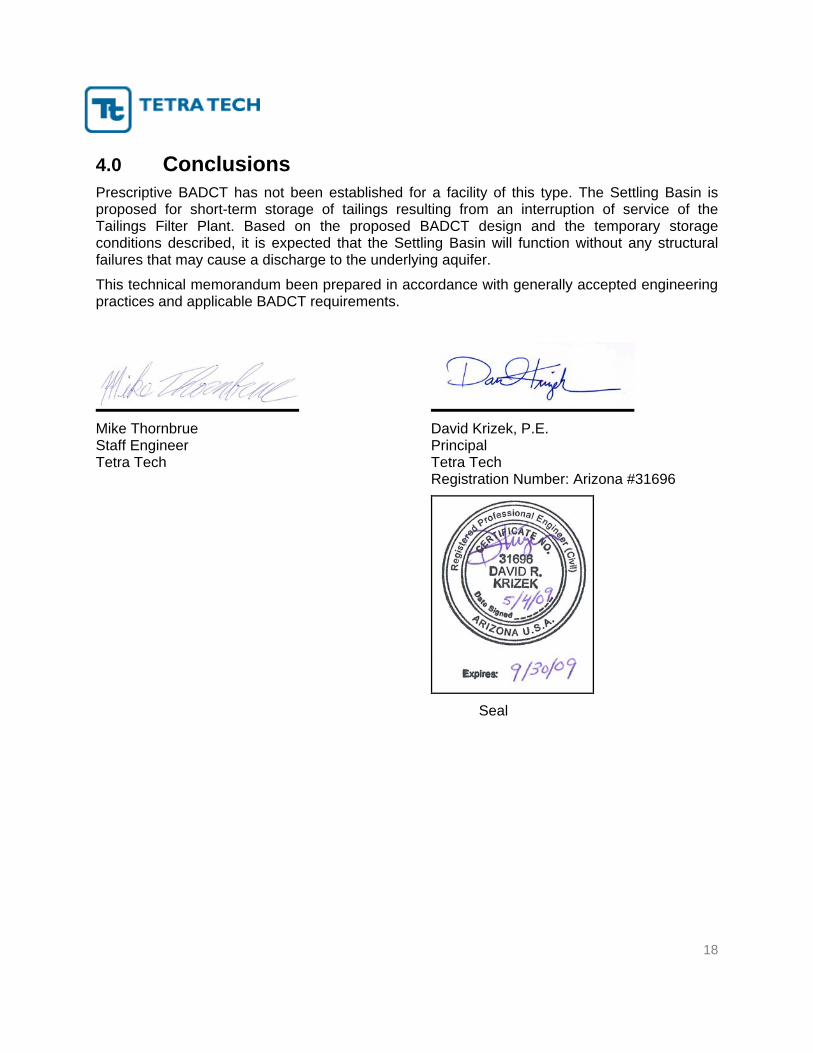
4.0 Conclusions Prescriptive BADCT has not been established for a facility of this type. The Settling Basin is proposed for short-term storage of tailings resulting from an interruption of service of the Tailings Filter Plant. Based on the proposed BADCT design and the temporary storage conditions described, it is expected that the Settling Basin will function without any structural failures that may cause a discharge to the underlying aquifer.
This technical memorandum been prepared in accordance with generally accepted engineering practices and applicable BADCT requirements.
Mike Thornbrue David Krizek, P.E. Staff Engineer Principal Tetra Tech Tetra Tech Registration Number: Arizona #31696
Seal

19
5.0 References ADEQ (2004), Arizona Mining BADCT Guidance Manual, Aquifer Protection Program,
Publication TB-04-01.
AMEC (2009) Dry Stack Tailings Storage Facility Final Design Report. Prepared for Rosemont Copper Company. Report Dated April 15, 2009.
Cetco Lining Technologies (2009). Claymax, Benomat, Properties, Panel and Roll Specifications: http://www.cetco.com/LT/GCL.aspx, Visited January 13, 2009.
Tetra Tech (2007) Geologic Hazards Assessment. Prepared for Rosemont Copper. Report Dated June 2007.
Tetra Tech, Carrasco, J. (2008) Rosemont Copper Heap Leach Facility Cost Estimate – Final. Memorandum to David Moll – M3. December 23, 2008.
Tetra Tech (2009a) Aquifer Protection Permit Application. Prepared for Rosemont Copper Company. Report Dated February 2009.
Tetra Tech (2009b) Geotechnical Addendum. Prepared for Rosemont Copper Company. Report Dated February 2009.

FIGURE