graphics gems from cryengine 3 (siggraph 2013)
DESCRIPTION
This lecture covers rendering topics related to Crytek’s latest engine iteration, the technology which powers titles such as Ryse, Warface, and Crysis 3. Among covered topics, Sousa presented SMAA 1TX: an update featuring a robust and simple temporal antialising component; performant and physically-plausible camera related post-processing techniques such as motion blur and depth of field were also covered.TRANSCRIPT

Tiago Sousa, R&D Principal Graphics Engineer
GRAPHICS GEMS

Advances in Real-Time Rendering course, Siggraph 2013 2
AGENDA
Anti-aliasing Practical Deferred MSAA
Temporal Antialiasing: SMAA 1TX
Camera Post-Processing Depth of Field
Motion Blur
Sharing results from ongoing research Results not used in a shipped game yet

Advances in Real-Time Rendering course, Siggraph 2013 3
ANTIALIASING\DEFERRED MSAA REVIEW
The problem: Multiple passes + r/w from Multisampled RTs DX 10.1 introduced SV_SampleIndex / SV_Coverage system value semantics.
Allows to solve via multipass for pixel/sample frequency passes [Thibieroz11]
SV_SampleIndex Forces pixel shader execution for each sub-sample and provides index of the sub-sample currently executed
Index can be used to fetch sub-sample from a Multisampled RT. E.g. FooMS.Load( UnnormScreenCoord, nSampleIndex)
SV_Coverage Indicates to pixel shader which sub-samples covered during raster stage.
Can modify also sub-sample coverage for custom coverage mask
DX 11.0 Compute Tiled based deferred shading/lighting MSAA is simpler Loop through MSAA tagged sub-samples
Advances in Real-Time Rendering course, Siggraph 2013 4
DEFERRED MSAA\HEADS UP !
Simple theory, troublesome practice At least with complex deferred renderers
Non-MSAA friendly code accumulates fast. Breaks regularly, as new techniques added without MSAA consideration
Even if still works.. Very often you’ll need to pinpoint and fix non-msaa friendly techniques, as these introduce visual
artifacts.
E.g. white/dark outlines, or no AA at all
Do it upfront. Retrofitting a renderer to support Deferred MSAA is some work
And it is very finiky

Advances in Real-Time Rendering course, Siggraph 2013 5
DEFERRED MSAA\CUSTOM RESOLVE & PER-SAMPLE MASK
Post G-Buffer, perform a custom msaa resolve Pre-resolves sample 0, for pixel frequency passes such as lighting/other MSAA dependent passes
In same pass create sub-sample mask (compare samples similarity, mark if mismatching)
Avoid default SV_COVERAGE, since it results in redundant processing on regions not requiring MSAA
SV_Coverage Custom Per-Sample Mask

Advances in Real-Time Rendering course, Siggraph 2013 6
DEFERRED MSAA\STENCIL BATCHING [SOUSA13]
Batching per-sample stencil mask with regular stencil buffer usage Reserve 1 bit from stencil buffer
Update with sub-sample mask
Tag entire pixel-quad instead of just single pixel -> improves stencil culling efficiency
Make usage of stencil read/write bitmask to avoid per-sample bit override
StencilWriteMask = 0x7F
Restore whenever a stencil clear occurs
Not possible due to extreme stencil usage? Use clip/discard
Extra overhead also from additional texture read for per-sample mask

Advances in Real-Time Rendering course, Siggraph 2013 7
DEFERRED MSAA\PIXEL AND SAMPLE FREQUENCY PASSES
Pixel Frequency Passes Set stencil read mask to reserved bits for per-pixel regions (~0x80)
Bind pre-resolved (non-multisampled) targets SRVs
Render pass as usual
Sample Frequency Passes Set stencil read mask to reserved bit for per-sample regions (0x80)
Bind multisampled targets SRVs
Index current sub-sample via SV_SAMPLEINDEX
Render pass as usual

Advances in Real-Time Rendering course, Siggraph 2013 8
DEFERRED MSAA\ALPHA TEST SSAA
Alpha testing requires ad hoc solution Default SV_Coverage only applies to triangle edges
Create your own sub-sample coverage mask E.g. check if current sub-sample uses AT or not and set bit
static const float2 vMSAAOffsets[2] = {float2(0.25, 0.25),float2(-0.25,-0.25)};
const float2 vDDX = ddx(vTexCoord.xy);
const float2 vDDY = ddy(vTexCoord.xy);
[unroll] for(int s = 0; s < nSampleCount; ++s)
{
float2 vTexOffset = vMSAAOffsets[s].x * vDDX + (vMSAAOffsets[s].y * vDDY);
float fAlpha = tex2D(DiffuseSmp, vTexCoord + vTexOffset).w;
uCoverageMask |= ((fAlpha-fAlphaRef) >= 0)? (uint(0x1)<<i) : 0;
}
Alpha Test SSAA Disabled
Alpha Test SSAA Enabled
Advances in Real-Time Rendering course, Siggraph 2013 9
DEFERRED MSAA\PERFORMANCE SHORTCUTS
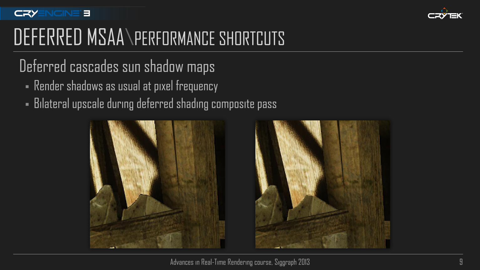
Deferred cascades sun shadow maps Render shadows as usual at pixel frequency
Bilateral upscale during deferred shading composite pass

Advances in Real-Time Rendering course, Siggraph 2013 10
DEFERRED MSAA\PERFORMANCE SHORTCUTS (2)
Non-opaque techniques accessing depth (e.g. Soft-Particles)
Recommendation to tackle via per-sample frequency is fairly slow on real world scenarios
Using Max Depth works ok for most cases and N-times faster

Advances in Real-Time Rendering course, Siggraph 2013 11
MSAA\PERFORMANCE SHORTCUTS (3)
Many games, also doing:
Skipping Alpha Test Super Sampling
Use alpha to coverage instead, or even no alpha test AA (let morphological AA tackle that)
Render only opaque with MSAA
Then render transparents withouth MSAA
Assuming HDR rendering: note that tone mapping is implicitly done post-resolve resulting is loss of detail on high
contrast regions

Advances in Real-Time Rendering course, Siggraph 2013 12
DEFERRED MSAA\MSAA FRIENDLINESS
Look out for these: No MSAA noticeably working, or noticeable bright/dark silhouettes.
Incorrect Incorrect

Advances in Real-Time Rendering course, Siggraph 2013 13
DEFERRED MSAA\MSAA FRIENDLINESS
Look out for these: No MSAA noticeably working, or noticeable bright/dark silhouettes.
Fixed Fixed

Advances in Real-Time Rendering course, Siggraph 2013 14
DEFERRED MSAA\RECAP
Accessing and/or rendering to Multisampled RTs? Then you need to care about accessing and outputting correct sub-sample
In general always strive to minimize BW Avoid vanilla deferred lighting
Prefer fully deferred, hybrids, or just skip deferred altogether.
If deferred, prefer thin g-buffers
Each additional target on g-buffer incurs in export rate overhead [Thibieroz11]
NV/AMD (GCN): Export Cost = Cost(RT0)+Cost(RT1)..., AMD (older hw): Export Cost = (Num RTs) * (Slowest RT)
Fat formats are half rate sampling cost for bilinear filtering modes on GCN [Thibieroz13]
For lighting/some hdr post processes: 32 bit R11G11B10F fmt suffices for most cases
Advances in Real-Time Rendering course, Siggraph 2013 15
ANTIALIASING + 4K RESOLUTIONS\WILL WE NEED MSAA AT ALL?
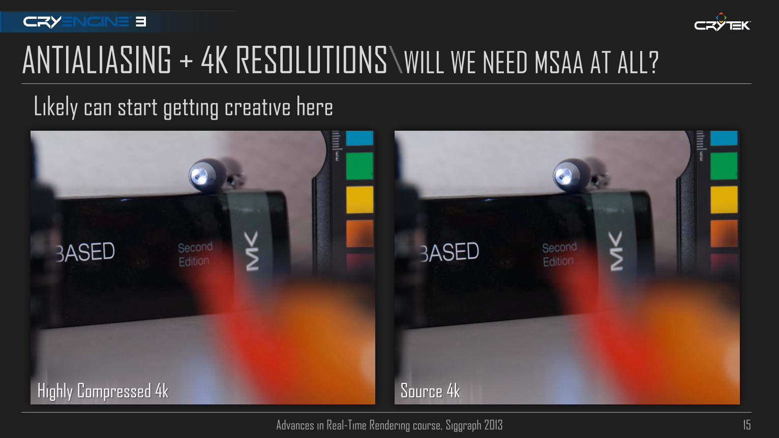
Likely can start getting creative here
Source 4k Highly Compressed 4k
Advances in Real-Time Rendering course, Siggraph 2013 16
ANTIALIASING \THE QUEST FOR BETTER (AND FAST) AA
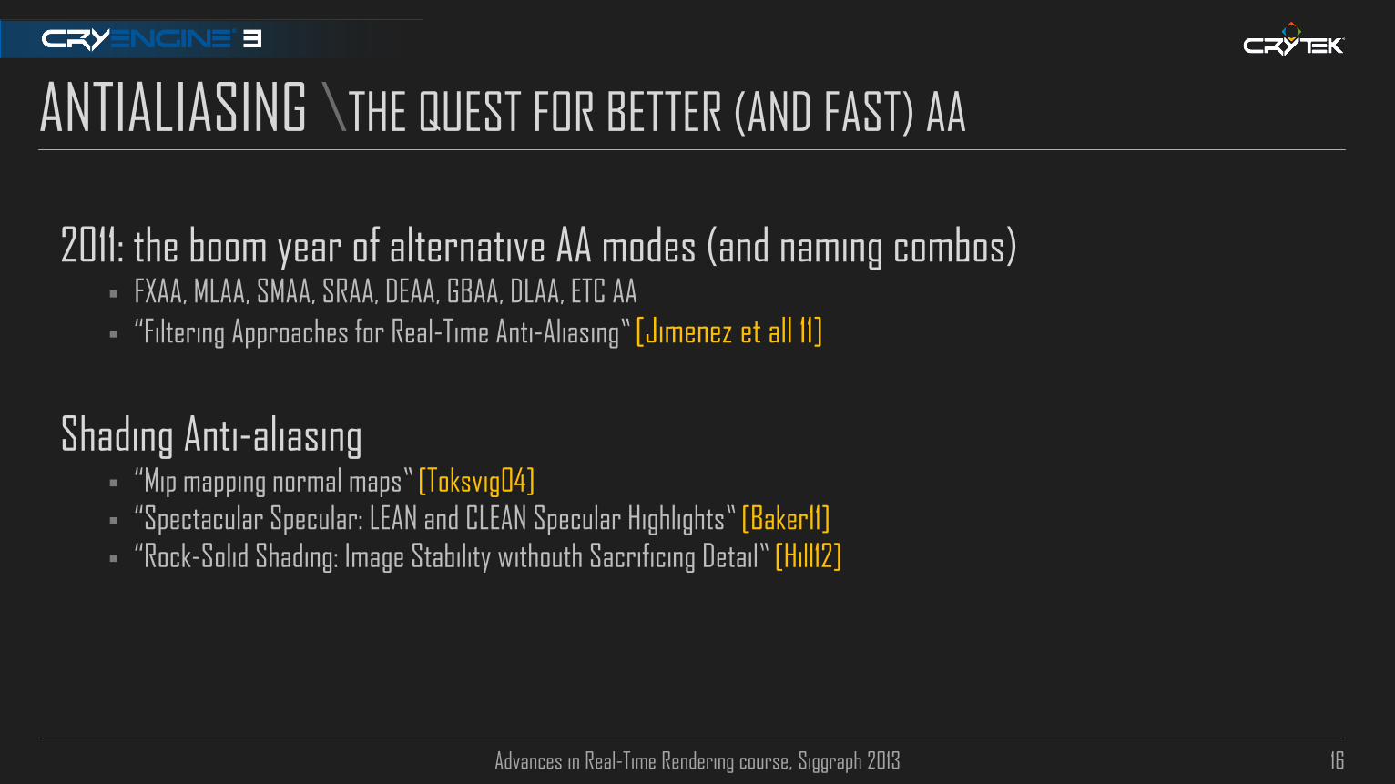
2011: the boom year of alternative AA modes (and naming combos) FXAA, MLAA, SMAA, SRAA, DEAA, GBAA, DLAA, ETC AA
“Filtering Approaches for Real-Time Anti-Aliasing” [Jimenez et all 11]
Shading Anti-aliasing “Mip mapping normal maps” [Toksvig04]
“Spectacular Specular: LEAN and CLEAN Specular Highlights” [Baker11]
“Rock-Solid Shading: Image Stability withouth Sacrificing Detail” [Hill12]

Advances in Real-Time Rendering course, Siggraph 2013 17
TEMPORAL SSAA\SMAA 2TX/4X REVIEW [JIMENEZ11][SOUSA11]
Morphological AA + MSAA + Temporal SSAA combo Balanced cost/quality tradeoff, techniques complement each other.
Temporal component uses 2 sub-pixel buffers.
Each frame adds a sub-pixel jitter for 2x SSAA.
Reproject previous frame and blend between current and
previous frames, via velocity length weighting.
Preserves image sharpness + reasonable temporal stability
Naive Blending Reprojection |V| weighting
Advances in Real-Time Rendering course, Siggraph 2013 18
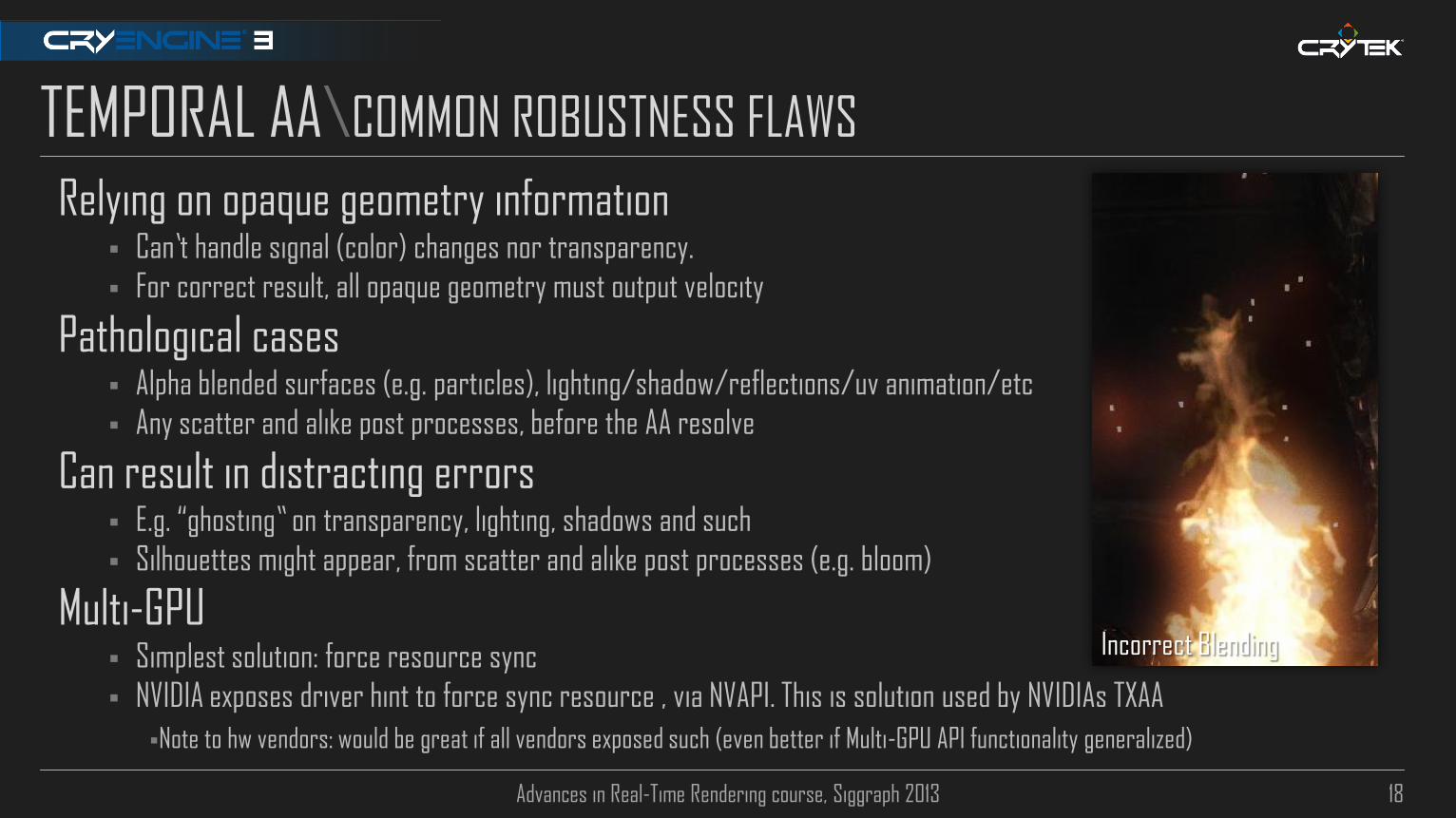
TEMPORAL AA\COMMON ROBUSTNESS FLAWS
Relying on opaque geometry information Can’t handle signal (color) changes nor transparency.
For correct result, all opaque geometry must output velocity
Pathological cases Alpha blended surfaces (e.g. particles), lighting/shadow/reflections/uv animation/etc
Any scatter and alike post processes, before the AA resolve
Can result in distracting errors E.g. “ghosting” on transparency, lighting, shadows and such
Silhouettes might appear, from scatter and alike post processes (e.g. bloom)
Multi-GPU Simplest solution: force resource sync
NVIDIA exposes driver hint to force sync resource , via NVAPI. This is solution used by NVIDIAs TXAA
Note to hw vendors: would be great if all vendors exposed such (even better if Multi-GPU API functionality generalized)
Incorrect Blending

Advances in Real-Time Rendering course, Siggraph 2013 19
SMAA 1TX\A MORE ROBUST TEMPORAL AA
Concept: Only track signal changes, don’t rely on geometry information For higher temporal stability: accumulate multiple frames in an accumulation buffer, alike TXAA [Lottes12]
Re-project accumulation buffer
Weighting: Map acc. buffer colors into the range of curr. frame neighborhood color extents [Malan2012]; different weight
for hi/low frequency regions (for sharpness preservation).
Current Frame (t0)
M
Accumulation Buffer (tN)
TL TR
BL BR M
Advances in Real-Time Rendering course, Siggraph 2013 20
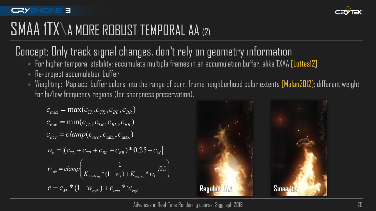
SMAA 1TX\A MORE ROBUST TEMPORAL AA (2)
Concept: Only track signal changes, don’t rely on geometry information For higher temporal stability: accumulate multiple frames in an accumulation buffer, alike TXAA [Lottes12]
Re-project accumulation buffer
Weighting: Map acc. buffer colors into the range of curr. frame neighborhood color extents [Malan2012]; different weight
for hi/low frequency regions (for sharpness preservation).
Smaa 1tx Regular TAA

Advances in Real-Time Rendering course, Siggraph 2013 21
SMAA 1TX\A MORE ROBUST TEMPORAL AA (3)
Sample code
float3 cM = tex2D(tex0, tc.xy);
float3 cAcc = tex2D(tex0, reproj_tc.xy);
float3 cTL = tex2D(tex0, tc0.xy);
float3 cTR = tex2D(tex0, tc0.zw);
float3 cBL = tex2D(tex0, tc1.xy);
float3 cBR = tex2D(tex0, tc1.zw);
float3 cMax = max(cTL, max(cTR, max(cBL, cBR)));
float3 cMin = min(cTL, min(cTR, min(cBL, cBR)));
float3 wk = abs((cTL+cTR+cBL+cBR)*0.25-cM);
return lerp(cM, clamp(cAcc, cMin, cMax), saturate(rcp(lerp(kl, kh, wk)));

Advances in Real-Time Rendering course, Siggraph 2013 22
DEPTH OF FIELD

Advances in Real-Time Rendering course, Siggraph 2013 23
DEPTH OF FIELD\PLAUSIBLE DOF: PARAMETERIZATION
Artist friendly parameters is one reason why games DOF tends to look wrong Typical controls such as “focus range” + “blur amount” and others have not much physical meaning
CoC depends mainly on f-stops, focal length and focal distance. These last 2 directly affect FOV.
If you want more Bokeh, you need to max your focal length + widen aperture. This means also getting closer or further
from subject for proper framing.
Not the typical way a game artist/programmer thinks about DOF.
Wider fov, less bokeh Shallow fov, more bokeh

Advances in Real-Time Rendering course, Siggraph 2013 24
50 mm
DEPTH OF FIELD\FOCAL LENGTH
200 mm

Advances in Real-Time Rendering course, Siggraph 2013 25
DEPTH OF FIELD\F-STOPS
2 f-stops 22 f-stops 8 f-stops

Advances in Real-Time Rendering course, Siggraph 2013 26
DEPTH OF FIELD\F-STOPS (2)
2 f-stops 2.8 f-stops 4 f-stops 5.6 f-stops
Advances in Real-Time Rendering course, Siggraph 2013 27
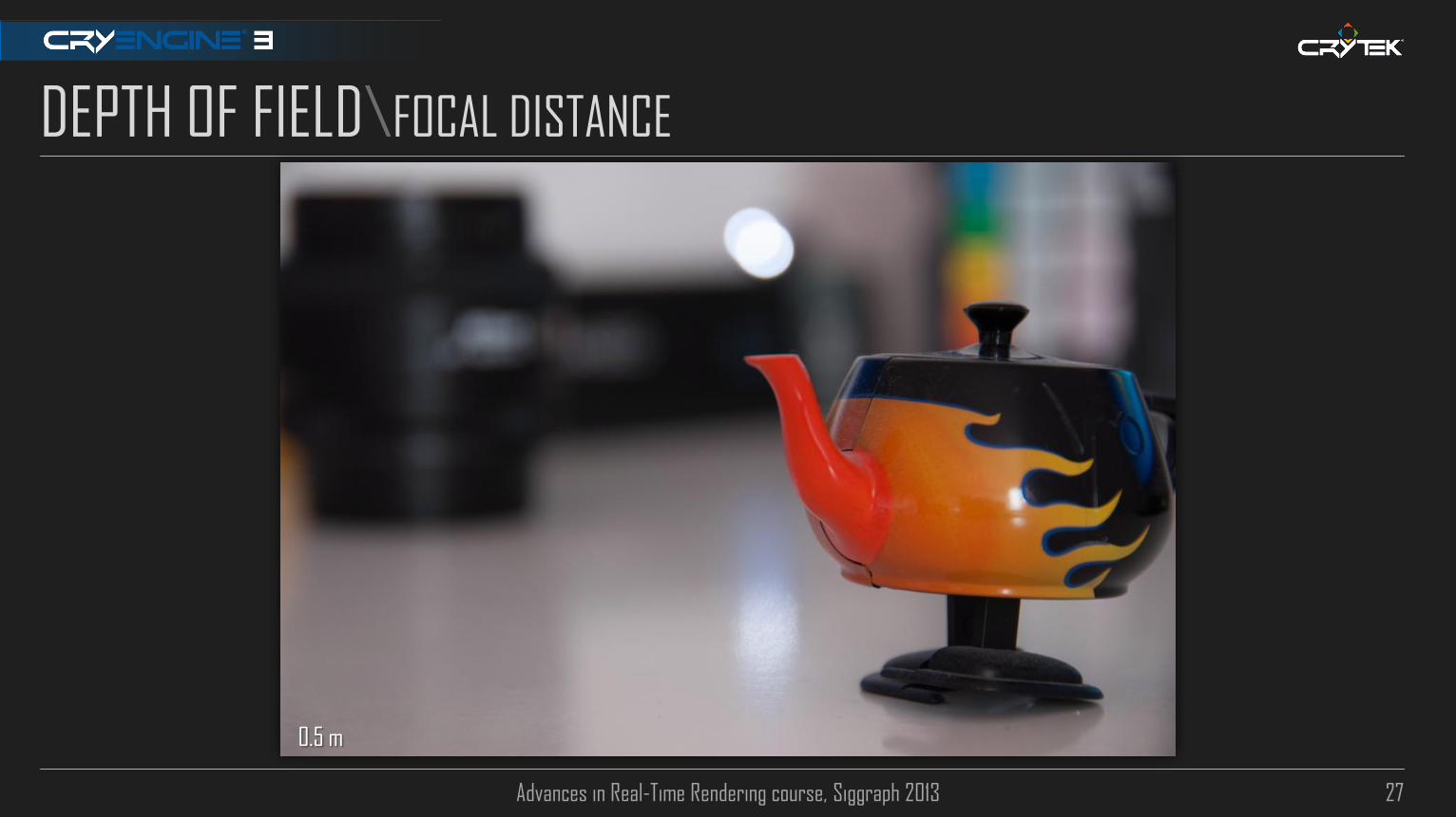
DEPTH OF FIELD\FOCAL DISTANCE
0.5 m

Advances in Real-Time Rendering course, Siggraph 2013 28
DEPTH OF FIELD\FOCAL DISTANCE
0.75 m

Advances in Real-Time Rendering course, Siggraph 2013 29
DEPTH OF FIELD\FOCAL DISTANCE
1.0 m

Advances in Real-Time Rendering course, Siggraph 2013 30
DEPTH OF FIELD\PLAUSIBLE DOF: BOKEH
Out of focus region is commonly referred in photography as “Bokeh” (J apanese word for blur)
Bokeh shape has direct relation to camera aperture size (aka f-stops) and diaphragm blades count Bigger aperture = more “circular” bokeh, smaller aperture = more polygonal bokeh
Polygonal bokeh look depends on diaphragm blades count
Blades count varies on lens characteristics
Bigger aperture = more light enters, smaller aperture = less light
On night shots, you might notice often more circular bokeh and more motion blur
Bokeh kernel is flat Almost same amount of light enters camera iris from all directions
Edges might be in shadow, this is commonly known as Vignetting
Poor lenses manufacturing may introduce a vast array of optical aberrations [Wiki01]
This is main reason why gaussian blur, diffusion dof, and derivative techniques look wrong/visually unpleasant

Advances in Real-Time Rendering course, Siggraph 2013 31
DEPTH OF FIELD\STATE OF THE ART OVERVIEW
Scatter based techniques [Cyril05][Sawada07][3DMark11][Mittring11][Sousa11]
Render 1 quad or tri per-pixel, scale based on CoC
Simple implementation and nice results. Downside: performance, particularly on shallow DOF Variable/inconsistent fillrate hit, depending on near/far layers resolution and aperture size might reach >5 ms
Quad generation phase has fixed cost attached.

Advances in Real-Time Rendering course, Siggraph 2013 32
DEPTH OF FIELD\STATE OF THE ART OVERVIEW (2)
Gather based: separable (inflexible kernel) vs. kernel flexibility
[Macintosh12]
[Gotanda09]
[White11] [Andreev 12]
[Kawase09]

Advances in Real-Time Rendering course, Siggraph 2013 33
DEPTH OF FIELD\A PLAUSIBLE AND EFFICIENT DOF RECONSTRUCTION FILTER
Separable flexible filter: low bandwidth requirement + different bokeh shape possible 1st pass N^2 taps (e.g: 7x7).
2nd pass N^2 taps (e.g: 3x3) for flood filling shape
R11G11B10F: downscaled HDR scene; R8G8: CoC
Done at half resolution
Far/Near fields processed in same pass
Limit offset range to minimize undersampling
Higher specs hw can have higher tap count
Diaphragm and optical aberrations sim
Physically based CoC

Advances in Real-Time Rendering course, Siggraph 2013 34
DEPTH OF FIELD\LENS REVIEW
Pinhole “Lens” A camera withouth lens
Light has to pass through single small aperture before hitting image plane
Tipical realtime rendering
Thin lens Camera lenses have finite dimension
Light refracts through lens until hitting image plane.
F = Focal lenght
P = Plane in focus
I = Image distance
Circle of
Confusion
Image Plane
P I
F

Advances in Real-Time Rendering course, Siggraph 2013 35
DEPTH OF FIELD\LENS REVIEW (2)
The thin lens equation gives relation between: F = Focal length (where light starts getting in focus)
P = Plane in focus (camera focal distance)
I = Image distance (where image is projected in focus)
Circle of Confusion [Potmesil81]
f = f-stops (aka as the f-number or focal ratio)
D = Object distance
A = Aperture diameter
Simplifies to: Note: f and F are known variables from camera setup
Folds down into a single mad in shader
Camera FOV: Typical film formats (or sensor), 35mm/70mm
Can alternatively derive focal length from FOV

Advances in Real-Time Rendering course, Siggraph 2013 36
DEPTH OF FIELD\SAMPLING
Concentric Mapping [Shirley97] used for uniform sample distribution Maps unit square to unit circle
Square mapped to (a,b) [-1,1]2 and divided into 4 regions by lines a=b, a=-b
First region given by:
Diaphragm simulation by morphing samples to n-gons
Via a modified equation for the regular polygon.

Advances in Real-Time Rendering course, Siggraph 2013 37
DEPTH OF FIELD\SAMPLING: 2ND ITERATION
To floodfill final shape, composite via boolean union, similarly to [McIntosh12]
+
U
+...=
U...=
Advances in Real-Time Rendering course, Siggraph 2013 38
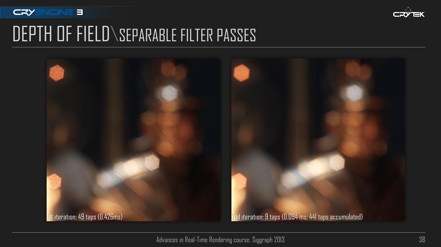
DEPTH OF FIELD\SEPARABLE FILTER PASSES
1st iteration: 49 taps (0.426ms) 2nd iteration: 9 taps (0.094 ms; 441 taps accumulated)

Advances in Real-Time Rendering course, Siggraph 2013 39
DEPTH OF FIELD\REFERENCE VS SEPARABLE FILTER
144 taps (1.31ms) 58 taps (0.52ms)

Advances in Real-Time Rendering course, Siggraph 2013 40
DEPTH OF FIELD\DIAPHRAGM SIMULATION IN ACTION
4f-stops 2f-stops

Advances in Real-Time Rendering course, Siggraph 2013 41
Tile Min/Max CoC Downscale CoC target k times (k = tile count)
Take min fragment for far field, max fragment for near field
R8G8 storage
Used to process near/far fields in same pass Dynamic branching using Tile Min/Max CoC for both fields
Balances cost between far/near
Also used for scatter as gather approximation for near field
Can fold cost with other post-processes Initial downscale cost folded with HDR scene downscale for bloom,
also pack near/far fields HDR input into R11G11B10F - all in 1 pass
DEPTH OF FIELD\TILE MIN/MAX COC
Tile min-CoC (far field)
Tile max-CoC (near field)

Advances in Real-Time Rendering course, Siggraph 2013 42
DEPTH OF FIELD\FAR + NEAR FIELD PROCESSING
Both fields use half resolution input Careful: downscale is source of error due to bilinear filtering
Use custom bilinear (bilateral) filter for downscaling
Far Field Scale kernel size and weight samples with far CoC [Scheumerman05]
Pre-multiply layer with far CoC [Gotanda09]
Prevents bleeding artifacts from bilinear/separable filter
No weighting CoC weighting CoC weighting +
CoC pre-multiply

Advances in Real-Time Rendering course, Siggraph 2013 43
DEPTH OF FIELD\FAR + NEAR FIELD PROCESSING
Both fields use half resolution input Careful: downscale is source of error due to bilinear filtering
Use custom bilinear (bilateral) filter for downscaling
Far Field Scale kernel size and weight samples with far CoC [Scheumerman05]
Pre-multiply layer with far CoC [Gotanda09]
Prevents bleeding artifacts from bilinear/separable filter
Near Field Scatter as gather aproximation
Scale kernel size + weight fragments with Tile Max CoC against
near CoC
Pre-multiply with near CoC
Only want to blur near field fragments (cheap partial occlusion approximation)
Far Field Near Field

Advances in Real-Time Rendering course, Siggraph 2013 44
DEPTH OF FIELD\FINAL COMPOSITE
Far field: upscale via bilateral filter Take 4 taps from half res CoC, compare against full res CoC
Weighted using bicubic filtering for quality [Sigg05]
Far field CoC used for blending
Near field: upscale carelessly Half resolution near field CoC used for blending
Can bleed as much as possible
Also using bicubic filtering
Carefull with blending Linear blending doesn’t look good (signal frequency soup)
Can be seen in many games, including all Crysis series (puts hat of shame)
Simple to address: use non-linear blend factor instead.
Linear blend
Non-linear blend (better)

Advances in Real-Time Rendering course, Siggraph 2013 45
MOTION BLUR

Advances in Real-Time Rendering course, Siggraph 2013 46
MOTION BLUR\SHUTTER SPEED AND F-STOPS REVIEW
Amount of motion blur is relative to camera shutter speed and f-stops usage The longer the exposure (slower shutter), the more light received (and the bigger amount of motion blur), and vice-versa
The lower f-stops the faster the exposure can be (and have less motion blur), and vice versa
2 f-stops, shutter 1/20 sec 4 f-stops, shutter 1/6 sec

Advances in Real-Time Rendering course, Siggraph 2013 47
MOTION BLUR\STATE OF THE ART OVERVIEW
Scatter via geometry expansion [Green03][Sawada07]
Require additional geometry pass + gs shader usage *

Advances in Real-Time Rendering course, Siggraph 2013 48
MOTION BLUR\STATE OF THE ART OVERVIEW (2)
Scatter as gather [Sousa08][Gotanda09][Sousa11][Maguire12]
E.g.velocity dilation, velocity blur, tile max velocity; single vs. multiple pass composite; depth/v/obj ID masking; single pass DOF+MB

Advances in Real-Time Rendering course, Siggraph 2013 49
MOTION BLUR\RECONSTRUCTION FILTER FOR PLAUSIBLE MB [MCGUIRE12]
Tile Max Velocity and Tile Neighbor Max Velocity Downscale Velocity buffer by k times (k is tile count)
Take max length velocity at each step
Motion Blur Pass Tile Neighbor Max for early out
Tile Max Velocity as center velocity tap
At each iteration step weight against full
resolution ||V|| and Depth
Advances in Real-Time Rendering course, Siggraph 2013 50
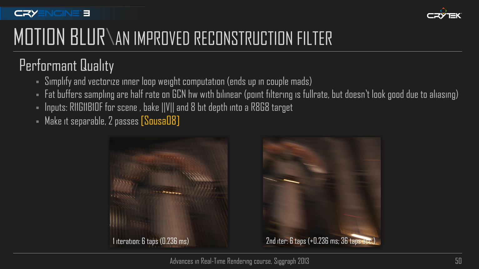
MOTION BLUR\AN IMPROVED RECONSTRUCTION FILTER
Performant Quality Simplify and vectorize inner loop weight computation (ends up in couple mads)
Fat buffers sampling are half rate on GCN hw with bilinear (point filtering is fullrate, but doesn’t look good due to aliasing)
Inputs: R11G11B10F for scene , bake ||V|| and 8 bit depth into a R8G8 target
Make it separable, 2 passes [Sousa08]
1 iteration: 6 taps (0.236 ms) 2nd iter: 6 taps (+0.236 ms; 36 taps acc.)

Advances in Real-Time Rendering course, Siggraph 2013 51
MOTION BLUR\AN IMPROVED RECONSTRUCTION FILTER (2)
Inner loop sample
const float2 tc = min_tc + blur_step * s;
const float lensq_xy = abs(min_len_xy + len_xy_step * s);
const float2 vy = tex2Dlod(tex1, float4(tc.xy, 0, 0)); // x =||v||, y=depth
const float2 cmp_z = DepthCmp(float2(vx.y, vy.y), float2(vy.y, vx.y), 1);
const float4 cmp_v = VelCmp(lensq_xy, float2(vy.x, lensq_vx));
const float w = (dot(cmp_z.xy, cmp_v.xy) + (cmp_v.z * cmp_v.w) * 2);
acc.rgb += tex2Dlod(tex0, float4(tc.xy, 0, 0)) * w;
wacc += w;
float2 DepthCmp(float2 z0, float2 z1, float2 fSoftZ) {
return saturate( (1.0f + z0* fSoftZ) - z1* fSoftZ );
}
float4 VelCmp(float lensq_xy, float2 vxy) {
return saturate((1.0f - lensq_xy.xxxx *rcp(vxy.xyxy)) + float4(0.0f, 0.0f, 0.95f, 0.95f));
}

Advances in Real-Time Rendering course, Siggraph 2013 52
Output object velocity in G-Buffer (only when required)
Avoids separate geometry passes.
Rigid geometry: object distance < distance threshold
Deformable geometry: if amount of movement > movement threshold
Moving geometry rendered last
R8G8 fmt
Composite with camera velocity Velocity encoded in gamma 2.0 space
Precision still insufficient, but not much noticeable in practice
MOTION BLUR\AN IMPROVED RECONSTRUCTION FILTER (3)
Encode
Decode
Object velocity
Composite with camera velocity

Advances in Real-Time Rendering course, Siggraph 2013 53
MOTION BLUR\MB OR DOF FIRST?
In real world MB/DOF occur simultaneously A dream implementation: big N^2 kernel + batched DOF/MB
Or sprite based with MB quad stretching
Full resolution! 1 Billion taps! FP16! Multiple layers!
But... performance still matters (consoles): DOF before MB introduces less error when MB happening on focus
This is due MB is a scatter as gather op relying on geometry data.
Any other similar op after will introduce error. And vice-versa.
Error from MB after DOF is less noticeable.
Order swap makes DOF harder to fold with other posts
Additional overhead
MB before DOF MB after DOF

Advances in Real-Time Rendering course, Siggraph 2013 54
FINAL REMARKS Practical MSAA details
Do’s and Dont’s
SMAA 1TX: A More Robust Temporal AA For just 4 extra texture ops and couple alu
A Plausible and Performant DOF Reconstruction Filter Separable flexible filter, any bokeh kernel shape doable
1st pass: 0.426ms, 2nd pass: 0.094ms. Sum: 0.52ms for reconstruction filter *
An Improved Reconstruction Filter for Plausible Motion Blur Separable, 1st pass: 0.236 ms, 2nd pass: 0.236ms. Sum: 0.472ms for reconstruction filter *
* 1080p + AMD 7970

Advances in Real-Time Rendering course, Siggraph 2013 55
SPECIAL THANKS Natalya Tartachuck
Michael Kopietz, Nicolas Schulz, Christopher Evans, Carsten Wenzel, Christopher Raine,
Nick Kasyan, Magnus Larbrant, Pierre Donzallaz

Advances in Real-Time Rendering course, Siggraph 2013 56
WE ARE HIRING !
Advances in Real-Time Rendering course, Siggraph 2013 57
QUESTIONS ?
[email protected] / Twitter: Crytek_Tiago
Advances in Real-Time Rendering course, Siggraph 2013 58
REFERENCES Potmesil M., Chakravarty I. “Synthetic Image Generation with a Lens and Aperture Camera Model”, 1981
Shirley P., Chiu K., “A Low Distortion Map Between Disk and Square”, 1997
Green S. “Stupid OpenGL Tricks”, 2003
Toksvig M., “Mip Mapping Normal Maps”, 2004
Scheuermann T., Tatarchuk N. “Improved Depth of Field Rendering”, Shader X3, 2005
Sigg C., Hadwiger M., “Fast Third-Order Texture Filtgering”, 2005
Cyril, P et al. “Photographic Depth of Field Rendering”, 2005
Gritz L., Eon E. “The Importance of Being Linear”, 2007
Sawada Y., Talk at Game Developers Conference, http://www.beyond3d.com/content/news/499 , 2007
Sousa T. “Crysis Next Gen Effects”, 2008
Gotanda Y. ”Star Ocean 4: Flexible Shader Management and Post Processing”, 2009
Yang L. et al, “Amortized SuperSampling”, 2009
Kawase M., “Anti-Downsized Buffer Artifacts”, 2011
Sousa T., “CryENGINE 3 Rendering Techniques”, 2011
Binks D., “Dynamic Resolution Rendering”, 2011
Sousa T., Schulz N. , Kasyan N., “Secrets of CryENGINE 3 Graphics Technology”, 2011
Sousa T., “Anti-Aliasing Methods in CryENGINE 3”, 2011
Jimenez J. et.al, “Filtering Approaches for Real-Time Anti-Aliasing”, 2011
Thibieroz N., “Deferred Shading Optimizations”, 2011

Advances in Real-Time Rendering course, Siggraph 2013 59
REFERENCES Cloward B., Otstott A., “Cinematic Character Lighting in Star Wars: The Old Republic”, 2011
Mittring M., Dudash B., “The Technology Behind the DirectX11 Unreal Engine “Samaritan” Demo“, 2011
Futuremark, 3DMark11 “White Paper”, 2011
Baker D., “Spectacular Specular: LEAN and CLEAN Specular Highlights”, 2011
White J., Brisebois C., “More Performance! Five Rendering Ideas from Batlefield 3 and Need for Speed: The Run”, 2011
Lottes T., “Nvidia TXAA”, http://www.nvidia.in/object/txaa-anti-aliasing-technology-in.html#gameContent=1 , 2012
McGuire M. et al, “A Reconstruction Filter for Plausible Motion Blur”, 2012
McIntosh L. Et al, “Efficiently Simulating Bokeh”, 2012
Malan H., “Real-Time Global Illumination and Reflections in Dust 514”, 2012
Hill S., Baker D., “Rock-Solid Shading: Image Stability withouth Sacrificing Detail”, 2012
Sousa T., Wenzel C., Raine C., “Rendering Technologies of Crysis 3”, 2013
Thibieroz N., Gruen H., “DirectX11 Performance Reloaded”, 2013
Andreev D., “Rendering Tricks in Dead Space 3”, 2013
http://en.wikipedia.org/wiki/Lens_%28optics%29
http://en.wikipedia.org/wiki/Pinhole_camera
http://en.wikipedia.org/wiki/F-number
http://en.wikipedia.org/wiki/Angle_of_view