gliding and gliders ii - scale soaring uk und... · wing construction ... rigid assembly to which...
TRANSCRIPT

[Back Cover]

[Front Cover]


Aircraft Construction and Aviation Commissioned by
The German Aviation Societies E.V.
Chapter 12
Gliding and Gliders by
F. Stamer and A. Lippisch Head of the Flying School
of the Research Institute of
the Rhön-Rossitten-Society e.V.
Head of the Technical Flight
Division of the Research Institute of
the Rhön-Rossitten-Society e.V.
Part II
Building Instructions and Drawings
with 8 illustrations and 5 plan sheets
Published by C. J. E. Volckmann and Sons, LLC
Berlin-Charlottenburg 2
Copyright 1927/28
Translated by James K. Hoffer

Table of Contents
Page
Aircraft Description . . . . . . . . . . . . . . . . . 5
Workplace and Materials . . . . . . . . . . . . . . 6
Building Instructions
1. Wing construction . . . . . . . . . . . . 7
2. Fuselage construction . . . . . . . . . . . 11
3. Construction of the empennage and
the control system . . . . . . . . . . . . 12
Final Assembly . . . . . . . . . . . . . . . . . . . 15
Parts Lists
1. Wing surfaces . . . . . . . . . . . . . . 17
2. Fuselage and tail boom . . . . . . . . . 18
3. Empennage . . . . . . . . . . . . . . . 19
Translator’s Postscript . . . . . . . . . . . . . . . 21
Construction Drawings Sheet
1. Assembly . . . . . . . . . . . . . . . . . 1
2. Wing with spars and hardware . . . . . . 2
3. Wing ribs . . . . . . . . . . . . . . . . . 3
3A. Rib verticals, diagonals, and gussets . . 3A
4. Fuselage with hardware . . . . . . . . . . 4
5. Horizontal and vertical tail sections . . . . 5


5
Aircraft Description
The “Sitzgleiter” [primary glider; literally “seat glider”]
depicted in the drawings is a braced monoplane consisting of the
following main parts:
right wing,
left wing,
support tower (cabane),
fuselage tail boom section,
tail surfaces (horizontal and vertical stabilizers),
rudder,
elevator,
control system.
It is shown in three principal views in the assembly drawing
[Sheet 1] and has the following dimensions:
length 5.3 m
height 2.0 m
wingspan 10 m
wing surface area ~15 m2
empty weight 65-70 kg
The aircraft is a training and practice glider designed in all
aspects for use by beginners.
The fuselage of the aircraft is built from sturdy wooden beams
reinforced on both sides with plywood sheeting.
The main controls and the hardware for the attachment and
bracing of the main wings are screwed onto the fuselage. In addition
to the controls, the pilot seat is located in the forward part of the
fuselage.
Four steel tubes that form two overlapping triangles having a
common base support the tailpieces of the aircraft.
The horizontal stabilizer forms the base that joins the tubing
triangles together. The vertical and horizontal stabilizers form a
rigid assembly to which the rudder and elevator are attached with
hinged bolts.

6
The wing uses the usual twin main spars and is internally braced
with guy-wires out to the flying wire brackets, while wooden
diagonal spars torsionally stiffen the unsupported outer sections.
The ribs are built up from capstrip spars and cross members, a
latticework supported by plywood gussets. Simple upright boards are
Figure 1.
Spar repair. (Gluing a doubly tapered board over the fracture on one
side accomplishes the repair.)
used for the main spars, mainly to provide the greatest possible
gluing surface for the eventual frequently needed repairs, Figure 1.
Workplace and Materials
Before beginning on such an aircraft, you must consider both
the workplace and the materials.
For the workplace, you should have an area of at least 6 m by
3.5 m with a height of 2.5 m.
Preferably, there is an exit leading directly to an outside open
area where you can assemble the aircraft. In any case, you should
verify that the door can accommodate assembled parts, such as the
fuselage assembly requiring a door height of 2.05 m.
The workplace should be equipped with a full complement of
cabinet-maker’s tools, such as a workbench, saws, a table saw,
planes, screw clamps, etc.
Now on to the materials.
One should realize that there are circumstances where one’s life
may depend on the quality of materials. Especially where aircraft
are concerned, the ‘best’ is just barely good enough. Due to the

7
necessity of saving weight, the materials are never thicker than
absolutely necessary and are highly stressed. Therefore
imperfections in materials can have dire consequences and much
care should be given to the selection process. Never let yourself
think, “This one will be good enough.”
For the wooden parts we use well-cured fir, with dead-straight
grain and no flaws. Southern German mountain fir is quite
acceptable.
Polish spruce also may be used for the main spars and the main
fuselage posts. With Polish spruce, it is easier to obtain the long
required lengths of blemish-free quality material.
The plywood indicated on the plan sheets is designated “birch
aircraft plywood,” available in the trade in all common thicknesses.
The various screws and bolts must be made from “SM-Stahl”
[stainless steel?]. Only metric threads are used. These screws and
bolts are found in the trade under “special aircraft screws.”
So-called “piano wire” is used for bracing, while braided steel
cable is used for the control connections.
The reader is referred to the advertisement sections [of this
booklet] for reference sources of the materials. All materials and
measurements are included in the parts lists.
Building Instructions
1. Wing Construction
Now we will begin the building phase, starting with the
construction of the wing.
After cutting out the wooden parts, build a jig for constructing
the ribs. Draw the full-scale rib profile on a flat board, along with
the positions of the upright and diagonal braces. Hammer in strong
nails such that the capstrips precisely follow the profile when laid
between the nails. Cut out the plywood gussets shown on the plans
as well as the upright and diagonal braces for all the ribs.
Now we can build the ribs, one after another, by spreading glue
on the plywood gussets, laying them down on the capstrips and
braces and securing them with flat-headed nails.

8
In this manner you assemble and glue each rib completely from
one side, then remove it from the jig and attach the plywood gussets
to the other side. Careful and accurate work is the order of the day.
It is simpler to assemble the type of ribs where the plywood
gussets lie between a double set of capstrips, because in this case the
work can be completed in the jig from just one side.
Figure 2.
Aileron diagonal braces and control horn installation.
There are four different kinds of ribs to be fabricated:
1. The ‘normal’ rib, wing part No. 2, made from a double set of
5 mm x 5 mm fir strips with 1.0 mm thick plywood gussets glued in-
between.
2. The normal aileron rib, wing part No. 2a, made in the same
way from 5 mm x 5 mm strips and 1 mm plywood, but having a slot
for the aileron spar. See Figure 2. The portion of the rib from the
rear spar slot forward is exactly the same as the normal rib 2. For
these ribs [2 and 2a] we use ~150 strips 5 mm x 5 mm x 1.6 m long.
3. The extra-thick rib, wing part No. 3, fabricated from 15 mm
x 5 mm strips with 1 mm plywood gussets on both sides. Because no

9
bracing diagonals or wires pass through these ribs, they have no
additional slots between the main spar slots. The layout is otherwise
the same as part 2. We will need eight of these ribs.
4. The extra-thick aileron rib, wing part No.3a, modified for the
aileron spar in the same way as 2a (two each).
For the thick ribs we need ~30 strips 5 mm x 15 mm x 1.6 m
long.
The main spars are then cut out exactly as shown in the drawing.
Figure 3a.
Forming the wire-eyes.
(Don’t forget to attach the spiral ferrule before bending the wire.)
Mark the position of each rib exactly on the spars and at this
time drill all the holes needed for attaching the hardware because this
will not be possible once the wing is assembled.
Lay both spars of one wing on a pair of sawhorses and slide on
the ribs in sequence, gluing them to the indicated positions. Then the
hardware can be attached. Square up the wing and install the guy-
wires for the internal bracing. Pay special attention to the form of
the wire-eyes. The formation of such a wire-eye is shown in figure
3a above. Don’t forget the ferrule for the wire-eye!
Be careful installing the wooden diagonals, parts 7 and 8, in the
outer wing section.
These diagonals run through the ribs, are anchored to them with
linen strips, and are attached to the spars with stout plywood gussets.
Counter-running strips of intersecting diagonals are given additional

10
anchoring at the middle. The inter-connection is accomplished with
plywood gussets glued in-between the strips because it is advisable
to use such a plywood connection wherever the wooden parts have
only a small gluing area. See Figure 4.
Slide the aileron spar into the ribs and glue the joints. 10 mm x
5 mm strips are added to the spar between each rib so that the height
of the spar matches the ribs. Install diagonal braces running from the
trailing edge, part No. 6, to both upper and lower sides of the aileron
spar. This scheme of triangular anti-torsion reinforcement is shown
Figure 3b.
Wire-eyes. (Bend with round-nose pliers, not with flat jaws.)
in figure 2. All the other control surfaces are built in this same
manner. The diagonal strips are anchored to the ribs where they
intersect with linen strips. Finally, the trailing edge strip, complete
with the plywood-reinforcing slat, is glued to the rear of the ribs [and
to the diagonals]. See Figure 2.
Before adding the plywood nose sheeting, it is necessary to add
filler strips to both top and bottom of the front spar because
otherwise the plywood will not lie flat along the spar between the
ribs. Use leftover 5 mm x 10 mm rib cap strip material laid
accurately between the ribs. Do the same to the rear spar only where
it is adjacent to the aileron spar. We have already equipped the
aileron spar with filler strips.
If we were to add filler strips to the inboard portion of the rear
main spar, kinks would occur in the covering due to the natural
tendency of the covering material to sag slightly between ribs.

11
Once everything is installed and the hardware has been
attached, the plywood nose sheeting and the planking at the first and
last rib are added. The plywood forces are carried by the extra-thick
ribs. Prior to gluing the plywood sheeting, dampen the outside of the
plywood with water to make it easier to bend. Dry plywood buckles
easily when bent.
Figure 4.
Diagonals in the outer wing panel and the aileron connection.
2. Fuselage Construction
Building the fuselage structure is simple. It is built right on the
workshop floor. Draw the exact outline of the structure and then nail
down a border of wooden blocks. Cut the main pieces to fit
accurately in this makeshift jig. As always, it is important to
accurately maintain the dimensions of the pieces. Wooden corner
blocks and plywood gussets are used to reinforce the corner joints.
The plywood on both sides of the fuselage assembly is 2.5 mm thick.

12
3. Construction of the Empennage and
the Control System
Building the tail surfaces requires 50 to 80 meters of 10 mm x
5 mm strip material for the ribs and diagonals. The eight ribs for the
horizontal stabilizer and the end pieces for the elevator halves are
built in a jig.
Figure 5a.
Control horn. (The spar fits through a notch in the control horn and
is anchored with a corner block on one side.)
Pay careful attention to the details in the drawing and follow
them precisely when preparing the double middle ribs.
The spars for the horizontal tail are again simple upright boards
(60 mm x 10 mm).
The rudder spar is a one-sided “ ”- spar, consisting of two
strips 9 mm x 10 mm and a 1 mm-thick plywood web.
Blocks and posts are glued in at the appropriate points to
reinforce the ribs and the control horns. Tips are made from 30 mm
x 40 mm strips, joined to the ends of the spars with plywood gussets.
Additional 20 mm wide blocks are glued in at these corners to
strengthen the ends of the spars where the bracing hardware is
screwed in.
The fin is built directly on the horizontal stabilizer. The fin spar
sits on top of the horizontal stabilizer spar and is connected to the
horizontal stabilizer at the front side with a block running through it
(50 mm x 10 mm x 200 mm) and at the rear with 1 mm plywood.
The leading edge is joined to the front spar of the horizontal
stabilizer by plywood angle gussets glued on the sides. A solid
wooden block connects the leading edge of the fin with the fin spar.

13
In the same manner as in the ailerons, triangular diagonal braces
reinforce the elevator and the rudder. The control surfaces are
hinged with the so-called ‘fork and eye’ bolts or small sheet-metal
hardware (see Chapter 11 of this series).
Figure 5b.
Control horn construction in the aileron.
The flying wires shown in the drawing reinforce the horizontal
stabilizer, primarily against landing jolts.
The fin is extended rearwards 30 mm by two plywood side
webs into which blocks are glued at the positions where the hinges
are attached. This extension allows the nearby rudder spar to swing
freely to either side.
The rudder horn fits around the spar and tight-fitting triangular
blocks add extra reinforcement to the connection. Refer to figures 5a
and 5b.
The empennage is suspended from the fuselage by four tubular
steel posts (30 mm O.D. x 0.8 mm wall thickness). The tubes are
flattened at the attachment points, the mating edges welded together,
and holes drilled for the attachment bolts. The upper supports are cut

14
off square at the rear ends and the lower supports lie with their
flattened ends under the upper ones. Drill several vertical holes
Figure 6. Mounting the wing
1 cm apart through the rear end of the upper supports to allow for
adjustment of the tail structure. The two sets of brackets built into
the horizontal stabilizer cradle the upper tubes from the sides and
connect to them with vertical bolts.

15
The steering structure is built up from steel tubing 30 mm x
1 mm wall. The control stick brackets and the aileron rocker-arm are
hard-soldered onto the roll tube. It is preferable to have these parts
prepared by an experienced welder.
The steering control cable pulleys and associated hardware are
available in the trade. The pulley blocks must be of high precision,
with rollers running freely, yet fitting tightly enough that the cable
cannot fall off.
Final Assembly
It is best to first assemble the aircraft before the covering is
applied, using the following steps.
Figure 7. Hardware bracket
Stand the cabane upright and attach the wings at the connecting
brackets (Figure 6a).
Add the four upper spar landing wires and tighten just enough
to give the wing a slight upward V-form (Figure 6b).
The ten turnbuckles, each having one forked end, are attached
directly to the spar hardware.
Now attach the lower flying wires and tighten until the wing
again lies flat (Figure 6c).
The rear lower spar bracket holds two wires attached as shown
in figure 7.
With the stabilizers already attached, hang the tail posts on the
fuselage and tension the structure with some 1.5 mm wire running
from the horizontal stabilizer rear spar brackets to the wing rear spar
brackets. There is nothing especially difficult about running the
aileron control cables (see the sketch in figure 8).

16
The aileron cables running from the rocker arms soldered onto
the torque tube to the double roller on the cabane are arranged so that
the cable coming from the right arm goes to the lower arm of the left
aileron control horn and vise-versa. The cable that joins the upper
arms of the aileron horns runs through a hole in the cabane. A
turnbuckle is spliced into the cable just off center in the right wing,
completing the loop and allowing for the proper centering of the
ailerons, both of which should lie exactly in the profile.
Figure 8. Aileron control cable scheme.
(See the fuselage assembly drawing for the elevator scheme).
Each steering cable under tension contains a turnbuckle for
adjustment. The sizes of all required turnbuckles appear in the parts
lists.
The application of the covering, etc., will not be discussed here.
You will need 45-50 m of material. Shirt linen, broadcloth, or
Cretonne (cotton drapery). Muslin is not suitable. The length given
above refers to the normal material width of 0.80 m.
If you desire to fire proof the covering material with waterglass
[sodium silicate], then you must use Cretonne because the other
materials will not shrink tight when waterglass is used.
Balance the aircraft accurately before the first flight (see the
section on aerodynamic calculations in Chapter 11).
For the first flight attempt, go to a flat area where you can carry
out hops of 100 to 150 m at low altitudes. Before flying, check the
flying wires and the action of the steering, especially whether the
direction of the control stick results in the correct motion of the
ailerons. It is easy to get the aileron controls reversed!

17
No. Name # Material Length Remark
1 Main spar 4 Spruce/Fir 90 x 12 4960
2 Normal rib 14 Fir 5 x 5 1500 1 mm plywood
2a " " (mod) 8 Fir 5 x 5 1500 1 mm "
3 Thick rib 8 Fir 15 x 5 1500 1 mm "
3a " " (mod) 2 Fir 15 x 5 1500 1 mm "
4 Wingtip 2 Fir 20 x 20 972
5 Aileron spar 2 Spruce/Fir 84 x 10 1913
6 Trailing edge 2 Fir 10 x 10 4600 1 mm plywood
7 Diagonal brace 2 Fir 10 x 10 1290 1 mm "
7a " " 2 Fir 10 x 10 1290 1 mm "
8 " " 2 Fir 10 x 10 1290 1 mm "
8a " " 2 Fir 10 x 10 1290 1 mm "
9 Ailieron horn 2 Fir 85 x 10 230 2 mm "
Aileron diagonal 4 Fir 10 x 10 793 to fit
" " 2 Fir 10 x 10 588.5 to fit
Leading edge sheeting 1 mm plywood
10 Tension wire bracket 8 Steel plate 15 x 1.5 85 5.2 mm hole
11 " " " 6 Steel plate 15 x 1.5 45 5.2 mm "
12 Wing bracing bracket assembly, 4 ea.
12a 8 Steel plate 1 mm thick
12b 4 Steel plate 1.5 mm thick
12c 4 Steel plate 2 mm thick
12d 4 Steel plate 2 mm thick
13 Wing-fuselage attachment assembly, 4 ea.
13e Spar bracket 8 Steel plate 2 mm thick
13f Fuselage bracket 4 Steel plate 2 mm thick
14a Pulley bracket 4 Steel plate 1 x 20 300 add 5.2 mm hole
14b Pulley 4 Aluminum 10 x 50 ∅ with bearing
Control cable Steel 7 x .25 ∅ 40 meter
Turnbuckle (wing bracing) 12 5 mm ∅ 70 Commercially available
Turnbuckle (cabling) 1 5 mm ∅ 71 Commercially available
Aileron hinges 6 Fork & Eye, See Part I
Cotter pin bolt 20 St. Steel 5 mm ∅ 15 with hole
Hex head bolt 8 St. Steel 8 mm ∅ 30 Metric thread
" " " 50 St. Steel 5 mm ∅ 30 Metric thread
Flying-wire (external) Music wire 2.5 mm ∅ Add ferrules
Guy-wire (internal) Music wire 1.5 mm ∅ Add ferrules
Cross Section
Parts List for
SitzgleiterWing

18
No. Name # Material Length Remark
1 Fuselage frame (heavy) 1 Spruce/Fir 70 x 35 8500 Gussets: 2.5 mm ply
Fuselage frame (light) " 35 x 35 7000 Sheeted w/ 2.5 mm ply
2 Tail boom assembly 1 Steel tubing 30 x 0.8 11800
2a Upper tubes 2 " 30 x 0.8 3300
2b Lower tubes 2 " 30 x 0.8 2600
3 Steering column 1 30 x 1
roll tube 1 " 30 x 1 1050
aileron tube 1 " 15 x 1 250
yoke 1 Steel plate 280 x 90 2
3a Rudder pedal bar 1 Oak 25 x 50 500
4 Tow hook 1 Steel plate 60 x 140 3
5a Pulley block 1 "
5b Double pulley block 1 "
6 Pulley shackle 2 "
7 Double pulley block 1 " 80 x 1.5 80
8a Lower flying wire bracket 2 " 40 x 1.5 210 5.2 mm hole
8b " " " " 2 " 40 x 1.5 210 5.2 mm "
9 Upper flying wire bracket 1 " 70 x 1.5 90
10 Wing coupling 4 "
11 Steering column straps 2 " 20 x 1.5 360
Control cable pulley 7 Aluminum 10 x 50 ∅ with bearing
Hex head bolt 30 St. Steel 5.2 mm ∅ 50 Metric thread
Turnbuckle (flying wires) 10 5 mm ∅ 70 Commercially available
Turnbuckle (empennage) 2 5 mm ∅ 70 Commercially available
Turnbuckle (cabling) 8 5 mm ∅ 71 Commercially available
Cross Section
Parts List for
SitzgleiterFuselage and tail booms

19
No. Name # Material Length Remark
1 Hor. stab. front spar 1 Spruce/Fir 60 x 10 1960
2 Hor. stab. rear spar 1 " 60 x 10 2500
3 Elevator spar 2 " 9 x 10 2500 1 mm plywood
4 Hor. stab. trailing edge 2 Fir 10 x 10 950 " " "
4 Rudder trailing edge 1 " 10 x 10 1250 " " "
5 Hor. stab. rib 8 " 10 x 5 620 " " "
6 Diagonal 2 " 10 x 10 1090 " " "
7 Hor. stab. tip rib 2 " 30 x 15 750
8 Elevator rib 6 " 10 x 5 380 1 mm plywood
9 Elevator corner support 4 " 10 x 10 490 " " "
10 Elevator diagonal 2 " 10 x 10 690 " " "
11 Elevator tip rib 2 " 30 x 10 400
12 Elevator horn 2 " 2 mm plywood
Hinged coupling 4 St. Steel Commerically available
13 Large bracket 4 Steel plate 20 x 1.5 140 5.2 ∅ hole
14 Small bracket 4 " 20 x 1.5 100 5.2 ∅ "
15 Leading edge 1 Fir 15 x 15 950 & 850
16 Fin spar 1 " 50 x 10 1200 Spdruce
17 Fin rib 4 " 10 x 5 1 mm plywood
18 Rudder spar 1 " 50 x 10 1500 Spruce
19 Rudder rib 6 " 10 x 5 480 1 mm plywood
20 Rudder corner suport 2 " 10 x 10 540 " " "
21 Rudder diagonal 2 " 10 x 60 680 " " "
22 Rudder horn 1 " 2 " "
Hinged coupling 3 St. Steel Commerically available
23 Tension wire bracket 2 Steel plate 20 x 1.5 100 5.2 ∅ hole
Turnbuckle 4 5 mm ∅ 50 Commercially available
Hex-head bolt 12 St. Steel 5 mm ∅ 60 Metric threads
Hex-head bolt 4 5 mm ∅ 15 " "
Cotter-pin bolt 4 " 5 mm ∅ 15 With hole
Guy-wire ( V. to H. stab) 4 Piano wire 1.5 mm ∅ 5000 Add spiral ferrules
Guy-wire (to wing) 2 Piano wire 1.5 mm ∅ 6250 Add spiral ferrules
Cross Section
Parts List for
SitzgleiterEmpennage

20

21
Translator’s Postscript
The photographs from this booklet did not photo-copy well from the
original. Making things worse, my JPEG copies are the result of a
second scan using my home printer. Therefore, the originals have
been replaced with digital photos of my 40%-scale replica of the
“Sitzgleiter.” Figure 2 is the clearest of the original photos, and
surprisingly, it shows some differences between the drawing sheets.
Because my model faithfully follows the Sitzgleiter drawing sheets,
it therefore shows the same differences. I have identified at least 5:
Figure 2 (original).
1). The support gusset surrounding the aileron horn is not a
triangle, as it is in Sheet No. 2.
2). The inboard diagonal brace in the aileron runs from the
inboard aileron end rib at the trailing edge to the next rib at the
aileron spar. But Sheet No. 2 shows the diagonal running the other
way, i.e., from the inner end rib at the spar to the next rib at the
trailing edge. Most of the photographs I have seen of the Stamer-

22
Lippisch ‘Zögling’ of 1926 (with an open, wooden fuselage) show
the first aileron diagonal running in this fashion.
3). The diagonal braces within the ribs themselves run opposite
to that shown in the plans on Sheet No.3. This includes the rib
diagonals in the aileron portion of the ribs.
4). As will be more apparent in the following figures, the extra
thick ribs have more uprights and hence shorter diagonals than
shown in Sheet No. 3.
5). The diagonal spars in the outer wing panel have slotted
webs, unlike that shown on Sheet No. 2.
― are there more?
Until I had finally finished the scale model wings and taken the
photographs to match the original points of view, only the first of
these five variances was obvious to me. My guess is that the wing
originally photographed was one from a 1926 Zögling that was
handy in the shop, but it was not the wing intended for this aircraft.
The original Figure 4, shown here, was difficult to decipher:
Figure 4 (original).

23
Of course, a great deal of this ambiguity is due to the fact that my
photo-copy of the original document was not of sufficiently high
resolution. But then, the original was not that clear either. This
photo does clearly show how the extra-thick ribs differ in having
more frequent uprights and shorter, more upright diagonals.
The original Figure 5b was much simpler, as seen here:
Figure 5b (original).
The five-sided shape of the plywood gusset around the aileron horn
is quite apparent. Another difference that can be detected here are
the gussets that support the aileron rib-to-spar junctions. They
appear to be more tapered than shown in Sheet No. 2.
In the German Virtual Aviation Museum you will find a side-view of
the “Stamer-Lippisch Zögling:” Compared to Sheet No. 1, there is
no obvious difference. However, Stamer and Lippisch themselves
never refer to the ‘Sitzgleiter’ as a “Zögling.” That name was
reserved for the earlier aircraft with a wooden, open-frame fuselage.

24
In his speech* delivered to the British Royal Aeronautical Society in
1931 entitled “The Development, Design, and Construction of
Gliders and Sailplanes”, Lippisch notes the following: “From
experience with the “Pegasus”, the “Zögling” (Beginner) was
developed, and as a further continuation of this series, the Stamer-
Lippisch glider, known in England as the “R. F. D. Dagling.” Martin
Simon reports† that he, along with many of his countrymen, learned
to fly in a “Dagling.”
http://www.luftfahrtmuseum.com/htmd/dtf/slzgl.htm
The 1929 manuscript How to Build…and…Fly Gliders‡ has several
photographs of a Sitzgleiter, including two of the wing ribs hung on
a fence. This shows that the Stamer-Lippisch pamphlets also made
their way to the States where a copy of the Sitzgleiter was built.
Following a visit to Holland by Lippisch in 1929, an aircraft nearly
identical to the Sitzgleiter was built in 1930 by Pander and Son. In
fact, it was the first aircraft built in Holland in 1930 and, using the
newly introduced international registration number system, it was
given the unique number: “PH-1”. A replica hangs in the
Aviodrome, the Dutch National Aviation Theme Park near Lelystad
Airport, the Netherlands. The museum note on this aircraft identifies
it as a Stamer-Lippisch Zögling Z-12, but I have not been able to
confirm this classification. Simons also noted that the Sitzgleiter
* Journal of the Aeronautical Society, p. 546, 1931(?). † Martin Simons, Sailplanes, 1920-1945, EQUP, p. 47, 2001 (ISBN 3-
9806773-4-6. ‡ Popular Book Corporation, 96-98 Park Place, New York, New York,
1929, see p. 13 for pictures of both types of ribs and p. 39 for a photograph
of the tail of a ‘Sitzgleiter” with a truncated rudder.

25
was produced in Switzerland by the Karpf Co. and sold as the “Karpf
Zögling.” It appears to be the same as the Sitzgleiter but with an
enclosed fuselage.
Although Simons credits§ Wolf Hirth with the development of
Zögling-like plans incorporating steel tubes for the rear fuselage, this
is clearly not warranted. In fact, the usage of four steel tubes
(forming two overlapping triangles whose common base is the main
spar of the horizontal stabilizer) pre-dates the present Sitzgleiter. In
1923-24, Lippisch, with the aid of the Steinmann Co., a
manufacturer of engine chains, built a school-glider called the
“Baby”. It became known as the Steinmann-Flugzeugbau ‘Baby’.
As can be seen from the following 3-view sketch from the memoirs
of Lippisch**, it also has the tubular-triangular rear-fuselage
arrangement.
Lippisch “Baby” (Steinmann-Flugzeugbau, 1924) ††.
If we credit the original design of this type of rear fuselage to any
specific person, it should be Lippisch. However, during the annual
§ Ibid, p. 44. ** A. M. Lippisch, Erinnerungen, Steinebach: A. Zuerl, 1980, pp. 78-83. †† The numbers are very difficult to read, but this aircraft appears to have a
wingspan of ~9 meters.
26
glider competitions at the Wasserkuppe that began in 1920, many
aircraft were entered that had steel tubing in the fuselage structure.
Perhaps this arrangement had been developed prior to 1923.
The original first-edition pamphlet was obtained from the U. S. Air
Force Academy Cadet Library‡‡, again with the superb help of the
Interlibrary Loan Department of the Los Alamos Public Library.
The value of this pamphlet to modelers such as myself is
immeasurably enhanced by the inclusion of detailed scaled
construction drawings. I had not expected this chapter to contain any
drawings at all because the lists found in previous chapters of
Flugzeugbau und Luftfarht [see the outside back cover, found at the
front of this translation] referred not to drawings, but to ‘Taflen’
[tables]. But, lo and behold, still attached to the rear of the booklet
were the five construction drawings sheets. They were brittle but
otherwise in perfect condition with absolutely no additional
markings. My impression was that they had never been opened!!
They were too large and fragile to copy in the library, so with the
permission of the Los Alamos Library I took them to a print shop in
Santa Fe where there was a flat-bed scanner large enough to
accommodate the sheets. They were not separated from the
pamphlet, but were unfolded and then protected by a large, clear
plastic cover sheet to avoid any damage while scanning. The
scanned TIFF files were ‘cleaned up’ using Adobe PhotoShop and
then used to make scalable AutoCad 2004 drawings. Later, I made
JPEG versions to include them here. In the JPEG’s, I have erased the
original German text and replaced it with English. The errors that I
have found in the drawings and in the parts lists are noted by a red X,
with my corrections adjacent.
‡‡ The USAF Cadet Library reference numbers for this volume are:
TLC 112, S78, v.2. A bar code was also added: 3 9333 00960001 6.
Unfortunately, the USAF Cadet Library has not allowed me any further
inter-library loans of the rare German booklets in their collection.

6
James K. Hoffer
Los Alamos, New Mexico
April, 2010


(not to scale)

(not to scale)

(not to scale)
1032
98
1146
930
1002
91.094.4
189.6
53.3
53.3
199.7
152.0179.9
156.6
93.8105.9
85.094.4
53.3
91.094.4
150.0154.7180.3179.3156.6
105.993.8
232.5 334.6322.3
170.8
199.7
310.8
310.6220.6
189.6
1007
1002
992
1490
1500
R25
680
675
651
646
382
377
353
348
1176
977
972
960668
370196
73
68
56
1468
1432
1171955
66351
365191
30
2222
2222
2222
20
20 12
2222
20
20
42
42
42
42
42
42
42
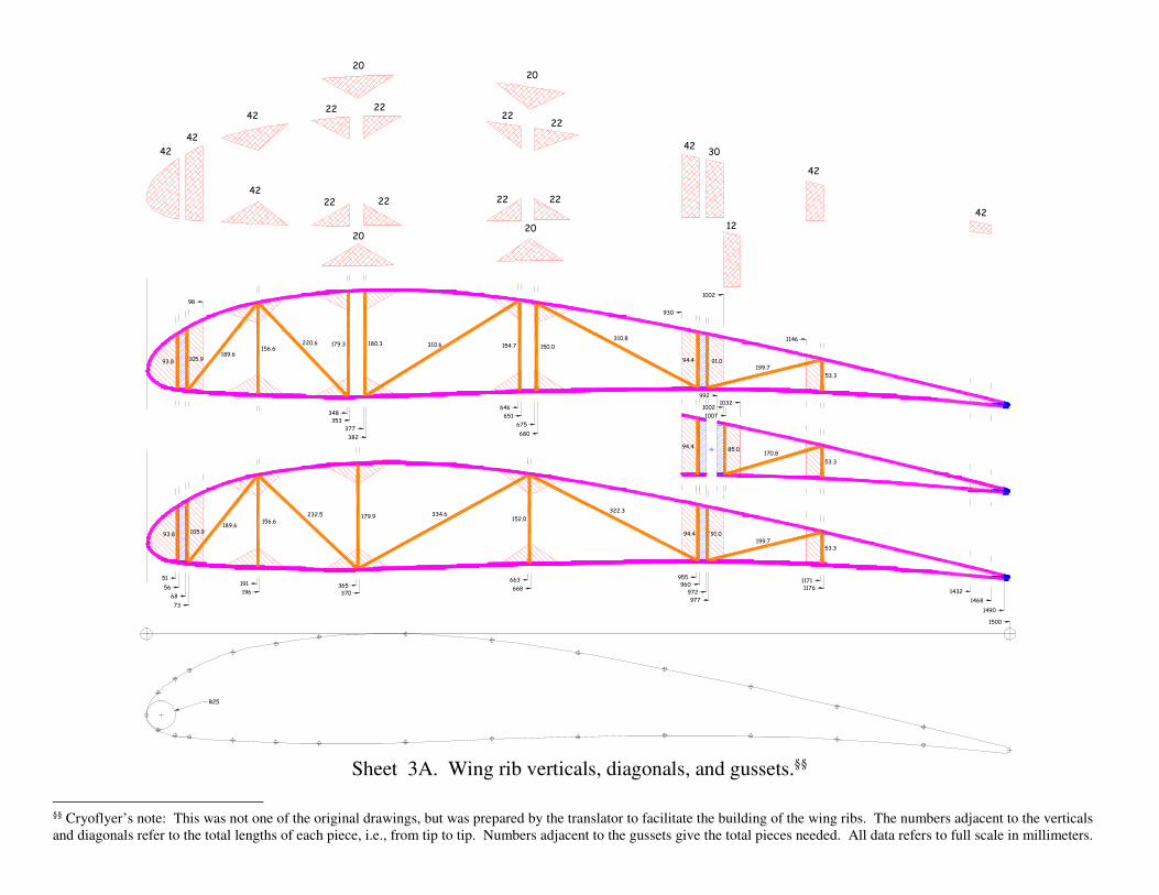
Sheet 3A. Wing rib verticals, diagonals, and gussets.§§
§§ Cryoflyer’s note: This was not one of the original drawings, but was prepared by the translator to facilitate the building of the wing ribs. The numbers adjacent to the verticals
and diagonals refer to the total lengths of each piece, i.e., from tip to tip. Numbers adjacent to the gussets give the total pieces needed. All data refers to full scale in millimeters.

(not to scale)

(not to scale)