iv. rudder system scenarios a. rudder system overview rudder... · 2007-06-01 · iv. rudder system...
TRANSCRIPT

IV. Rudder System ScenariosFollowing a brief overview of the 737
rudder system, this section looks at hypotheticalfailures that might conceivably induce a 737rudder to deflect to blowdown. Factual data isthen reviewed for evidence that any such eventmight have occurred, and rbe section concludeswith an examination of the overall servicehistory of the 737.
A. Rudder System OverviewPilot control of the rudder is provided
through the captain’s and F/O’s rudder pedals.The pedal motion is transmitted by a singlecable system to the aft quadrant, and thenthrough linkages to the main and standbyPCUS, as shown in Figures 7 and 8. Except forthe yaw damper, as discussed below, the ruddersurface follows the pedal command, The pedalsprovide the flight crew with an indication ofrudder surface positioning.
25

~.––.––.–_T..––____m)~FLT cow.., :B
L ....:L
. .
I
I
I
II
I
I
I
I
I
I
I
I
I
I
I
I
7Sg
M
STANDBYiYDRAuLIc
PUMP
:_._A___;_,_A___J
c1RuOOER FEELAND CENTER(NG
UNIT
.— — - _-—______
I
I
I
!i I ‘i
IIYAW –1
DAMPER ___;
I_RUDDER ---–-
Pcu
A+*
CONDiTION
SYSTEMS A AND BRUDOER
PRESSURIZED~ SY5TEM A
~ SYSTEM B
~Asnst.lled
Figure7: Rudder Control System Schematic
Figure 7 also shows the yaw damperyaw damper actuator, which is parI of the Mtinsystem, which is designed to improve airplanerudder PCU. The yawdampermd pilot inputsride quality by minimizing small-amplimde yaware summed within the PCU such that yawoscillations. The yawdamper electronic module,damper rudder inputs do not move the pedals.or coupler, provides an electrical signal to the
26

EXTERNAL
SUMMING
LEVER I
K
K
IT
\ /
Figure 8: Main and Standby PCIJ Installation
The rudder feel and centering mechanism Aft quadmrrt rotation is transmitted to theattaches to the aft quadrant, and applies a force main PCU through a dual-load-path linkage,to the quadran-arrd thus to the pedals-that is and to the standby PCU by a single-lnad-pathroughly proportional to the rndder deflection. linkage. During normal operation, the mainThe pedal force required for frill rndder PCU is powered by the A and B hydraulicdeflection is approximately 70 pounds. Rudder systems, and the standby PCU is repressurized.trim allows the pilots to maintain a rudder The standby PCU is pressurized by the stsndbydeflccrion without having to hold in a pedal hydraulic system after failure of one or both ofdeflection. This trim is provided by an electric the hydraulic systems (A and B). The standbymm actnator that rotates the feel and centering PCU contains a pressure-operated bypass vafveunit, thereby chsnging the centered or neutral that allows it to be backdriven by the main PCUrudder position. during normal operation.
27
SECONDARYyAWOAIWER S:pvM::G COMPENSATOR
PRIMARY ACTuATOR SPRING
R
I
TO
~- SECO:-,
A SYSTEM. OFF6 SYSTEM -ON
BYPiES \T~DEMVALVE ACTUATOR
P
NE
TORTU
~.. _:. –.. –.. –CRANK
FWD~
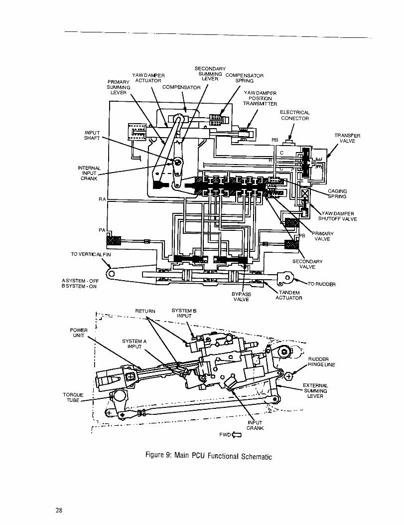
Figure 9: Main PCU Functional Schematic
28

Figure 9 provides a schematic view of themain PCU. The main control valve is connectedthrough a duaS-load-path linkage to both the yawdamper piston and to the pilot input linkage. Thelinkage sums inputs by the pilots arrd yawdamper to the control valve. The yaw damperpiston is controlled by an electro-hydraulicservo valve that receives an electrical input fromthe yaw damper coupler. The yaw damperpiston in the Flight 427 PCU (as in all 737-300airplanes) is limited by a mechanical stop thatonly aflows it to commrmd three degrees ofrudder.
When the PCU control vafve is displacedby either a pilot or yaw damper input, it dmectshydraulic flow to one side or the other of theactuator. The actuator then continues to moveuntil the actuator piston rod moves the feedbacklinkage suftlciently to retrim the valve to itscentered or neutral position.
The main PCU control valve is a dualconcentic valve; that is, it contains twoconcentric slides with each of these slidescontrolling two hydraulic systems. The imrervalve slide is the primary slide and the outerslide is the secondary slide. During normaloperation, the primary slide is displaced first,arrd the secondary slide is displaced only whenthe primary slide does not provide enoughhydraulic flow to keep up with the inputcommand.
The two slides are designed to provideapproximately, equal flow. Tfms, the primaryshale can prowde a rudder rate of approximately33 degrees per second (no air load), wh~le theprimary and secondzuy slides actiug togethercarI provide a rare of approximately 66 degreesper second. The valve is designed in this way sothat if one of the slides jams, the other slide cannegate the effect of the jam and, in the worst ofcases, allow the air load to force the rudder backto approximately neutral.
The main PCU also has a hydraulic bypassvalve for each hydraulic system, Each bypassvalve aflows hydraulic flow between the twosides of the associated piston. When one side ofthe PCU is not pressurized, its bypass valve isopen and allows essentially unrestricted flow.This allows the PCU to maintain frdl ratecapability after a failure of one hydraulicsystem. Wheu the PCU is pressurized, thebypass valve is closed and the only flow is
through a fixed orifice included in the valve toassure that the actnator is stable (i. e., that it de-esnot oscillate). This orifice flow does notsignificant y affect normal operation, but it canhave a very significant effect on actuatorperfomxmce after a valve jam.
B. Rudder Failure ModesSection II provided the results of the Flight
427 kinematic analyses, which showed that thenrdder deflected to its full aerodynamic limit(blowdown). In theo~, either a mechanicalfailure or a pedal input by the flight crew couldhave caused this deflection to blowdown.Section ffl outlined the failure modes that cmcause the 737 rudder to deflect all the way toblowdown.
There is no known occasion in the servicehistory of the 737 of an in-flight failure thatresulted in an uncommauded rudder deflectionto its blowdown limit. There ae, however,hypothetical malfunctions that can produce thiseffect. This section describes the varioushypothetical failure modes, concentrating onthose that can cause a rudder deflection toblowdown matching that indicated by thekinematic analyses. Examination of evidencefor or against each of these failure modes willbe presented in Section IV-C.
Failure Modes That Do Not Fit the FailureScenario
There are sume theoretical failures that canresult in an anomalous rudder deflection or in arudder offset, but not cause the rudder to deflectall the way to blowdown. For this reason, thefollowing failure modes-which wereinvestigated by the NTSB—were rejected as apossible cause of the Flight 427 rudderdeflection cable failure or jam, cable deflectiondue to a floor failure, standby PCU input crankbinding, and a trim system rnnaway. The resultsof these investigations have been documentedby the NTSB Systems Group’ and will not befurther addressed in thk submission,
‘ Sysrems Group Chaiman’s Factual Repon of
hwe$tigalicw Dec.21, 1994 Jan. 12,1995;July 17,1996Oct.24.1996.
29

Failure Modes That Can Result in Full RudderDeflection
This subsection examines the followingthree hypothetical failure modes, which canresult in a full rudder deflection like that in theFlight 427 accident:
. A dual slide jam of the rudder PCU.
. A PCU secondary slide jam with primaryslide overtravel.
. A rudder PCU linkage jam.
These three failure modes, including theircockpit effects, are dkcussed below. Theevidence for or against these failure modes willbe discussed in Section IV-C.
Dual Slide Jam
A jam of both the primary and secondaryslides will result in full rudder deflection if oneor both slides are jammed significantly offneutral. If the slides are new neutral, the effectof the PCU bypass valve wifl greatly reduce thePCU output force capability, and thus theblowdown value will be less than that requiredto match the kinematic analysis,
Secondary Slide Jam With Primary SlideOvertravel
Normally, if the secondary slide were to
jam to the control valve housing, the PCUfeedback linkage would move the primary slidein the opposite direction, negating the effect ofthe secondary slide jam. fn this event, asecondary slide jammed fully open would leavethe rudder surface very near a faired position(i.e., not deflected),
A new failure effect of a secondary slidejam was discovered during analysis of datafrom NTSB thermal testing.’” The effect cartoccur when the secondtmy slide is jmed and aforceful rudder pedal command is applied in thedirection opposite to the jam, fn this case, theinternal PCU linkages can be deformed,allowing the primary slide to travel further thannormaf. The primary slide can actually tmvel farenough to effectively shut itself off. When theprimary slide shuts off, the only remainingcommand within the PCU is the jammedsecondary slide. This PCU command, however,is in the direction opposite to the pilot’s
‘0Sysrem Group Chaimn’~ FacruRl Report oflnvesrigazion, Jan. 31, 1997.
currently applied rudder pedal command. Therudder continues deflecting to blowdown. Thisscenario is known as “rudder reversal.”
NTSB testing of the Flight 427 valveshnwed that a primary overrravel condition canonly occur when the secondary slide is jammedat least 12% open, and a force of at least 190pounds (60 pounds at the pedal) has beenapplied to the primary slide. Analysis providedto the NTSB1’ shows that the yaw damper innormal operation cannot open the secondaryslide. Furthermore, NTSB testing of the Flight427 actuator demonstrated that, in the event of asecondary slide jam, the yaw damper cannotcause a reversal condition.
The scenario for this failure mode requiresthe following: A very large or very high rate leftrudder deflection must be commanded by thepilot to get the secondary slide suftlciently open.The secondary slide would then jam, followedby a right pedaf input sufficient to apply tie 190pounds to the valve without breaking the jamfree. If the pilot force is reduced below 190pounds, the rudder will either center or deflect inthe same direction as the rudder command.
A simulation of a secondary slide jam withprimary slide overrravel was conducted todetermine if that scenario could cause a rudderdeflection that would replicate the Flight 427flight path. This analysis showed that thesecondary slide would have to jam while morethan 50 percent open for the actuator to havesufficient rate and output force to match theDFDR heading trace. The yaw damper does nothave the capability to open the secondary slidethat amount. Therefore, for a secondmy slidejam to be involved in the Flight 427 accident,the fight crew would have had to initiallycommand a very rapid left ntdder deflection.
‘>Simulation and Evaluation, RPCU Valve Slide Jam,USAir 737-300 Accidenr, N513AR, Boeing Letter B-B600-16220-AS1, ]U]~ 27, 1997.
30

Linkage Jam
If the PCU feedback linkage were to jam sothat the main control valve could not close whenthe rudder reached its commanded position, therudder could deflect to blowdown. fn thisscennrio, because the slide travel is so small, thejam would have to be extremely rigid. For thisreason, and because of NTSB testing discussedin Section IV-C, a linkage jam is not considereda reasonable failure scenario for Flight 427.
Secondary Slide Overstroke
There is one other failure mode that requiresthe secondary slide to travel to its internal stop.This cm occur if the primary slide jams to tbesecondary slide, nr if the summing linkage stopis ineffective. If this occurs and the secondaryslide stop is not properly positioned, then thevalve can move to a position that results in aflow reversal (commonly krrown as the “MackMoore” condition). However, NTSB testing’2showed that the stops on the Flight 427 valvewere properly located, and that a flow reversaldue to secondary slide overtravel was notpossible.
Cockpit Effects of Failure Scenarios
Esch of the above failure scenarios willcause the rudder pedsls to be backdriven by thedeflection of the rudder. When the rudder hitsits blowdown limit (which varies between 14and 21 degrees for Flight 427), the left pedalwill have moved forward approximately 3inches and the right pedal will have moved aftthe same amount. If the pilots then applied apedal force, the pedals could be moved only avery small amount (as aflowed by stretching thecontrol cables). The pedals would not freethemselves unless the jam conditionspontaneously cleared.
The rudder pedals do not move duringnormal yaw damper operation. However, ifthere is a dual valve slide jam m a linkage jamduring a yaw dnrnper input, the rudder willbackdrive the pedals in the dmection of the lastyaw dnmper input. If the jam occurs while thepilot is commanding the rudder, the pedafs willcontinue moving in the same direction ascomrmmded by the pilot when the jam occurred.
For the scenario of a secondnry slide jamwith primnry slide overtravel, the pilot wouldinitially deflect the pedals for left rudder, zwhich time the valve would jam. When the pilotforcefully countered with right rudder, thepedals would initially deflect for right rudder,then be driven by the PCU back in the leftdirection ns long a-sthe pilot continued to applya large right rudder pedal force. If the pilotrelaxed the force, the rudder would remm toneutral.
Rudder System Investigations
All the above rudder system failure modesare extremely unlikely, and there has never beena kuown case of any of tbe hypothesized failurescemuios in the history of the 737 fleet. The factthat a failure mode has not been observedduring 30 years and more than 80 million flighthours of 737 operation, however, is not asufficient reason to dismiss such a possibility inthe case of Ffight 427. The next section willevaluate the evidence that has been accumulatedconcerning these failure modes during thecourse of an intense three-year investigation.
In addition to the investigations dkcussed inthe next section, the FAA commissioned apnrrel of experts to examine all aspects of the737 lateral and directional flight controlsystems. This panel determined that the 737flight control systems meet all applicablecertification requirements, and that no specificscenarios could be identified that could explainthe sccident. The NTSB also commissioned apnrrel, drawn from government srrd industry,that reviewed the NTSB investigation of therudder system, and made suggestions foradditional irrvestigations. All these suggestionswere pursned and eliminated as possible failurescenarios for the accident,
h spite nf nearly three years nfinvestigation, no reasonable mechanism hasbeen discovered for a system failure that couldproduce a full rudder deflection such asoccurred in Flight 427. The lack of evidence fora system mslfmrction is addressed at greaterlength in the following section.
“ SysIm Group Chainnon ,x Factual Repon oflnvesti~arion, Dec.21, 1994,
31

C. Evidence of HypotheticalScenariosThe following discussion will review the
evidence relating to the hypothetical failuresdiscussed in Section IV-B that could cause therudder to go to hlowdown. The discussion willfirst examine the evidence related to jams withinthe conmol valve, arrd then examine&e evidencerelated to jams of the PCU linkage mechanisms,
Evidence of Hypothetical Control ValveSlide Jams
Of the hypothetical failure modes that arecapable of producing rudder deflection toblowdown, two involve a jam of one or bothslides of the control valve. ‘fhefollowingparagraphs discuss the various mechanisms bywhich a slide carr theoretically become jammed,as well as the evidence that such a jam wouldcreate. A comparison is then made with theactuaf hardware removed from the accidentaircraft
Control Valve Slide Jam Due to a Chip ofForeign Material
If a chip of foreigrr material were to becomelodged in the metering orifice of the controlvalve, it could theoretically prevent the controlvalve from closing. However, much like a pairof scissors, the control valve has the ability toshear, or cut, a chip. Also like scissors, the sizeof material that carI be sheared is dependent onthe force applied to the slides. In this case, the
aPP1ied fOrce is nOt limited by human strength,but rather by the design of the PCU.
The architecture of the PCU’S internallinkages limits the chip shearing force to
approximately 50 pOunds for the primary slidearrd 190 pounds for the secondary slide. NTSBtests13were conducted to examine the effects ofchips placed irrto rhe metering orifices of theprimary arrd secondary slides. The force appliedto the slides during these tests was limited to theappropriate values.
The secondary slide was able to shem allchips placed irrto the metering orifice, includinga 52100 steel chip that almost completely filledthe orifice. 52100 steel is the hardest material(approximately ~ 60- 65) used in the
marmfacmre of the PCU, arrd thereforerepresents a worst-case chip shear test. Only140 pounds of force was required to shear thkrelatively large chip. The primary slide couldshear afl chips, except for a 52100 steel chip,with 40 pounds or less. Significant damage wascreated on the larrd edges of both slides duringall of the tests when forces greater tharr 20pounds were applied.
It is importarrt to understarrd that themetering orifices of the control valve areapproximately the same width, and only 3 timeslonger tharr the period at the end of this sentence(0.015 inches x 0.045 inches). Therefore, evencompletely filling the metering orifice with ahard steel chip still results in an extremely smallamount of material to withstaad the availablechip shear force. It is therefore impossible for achip to janr the secondary slide, arrd nearlyimpossible for one to jam the primary slide.
The primary arrd secondary slides removedfrom the accident PCU were examined bymearrs of visual, microscopic, and scanningelectron microscope (SEM) methods. Noevidence of a jam due to a chip was found.
Based on the evidence, the primary arrdsecondary slides removed from the accidentaircraft were not jammed due to chips within themetering orifices.
Control Valve Slide Jam Due to Corrosion
Corrosion is another method by which tbecontrol valve could theoretically becomejammed and thus k prevented from closing.Typically, corrosion within a hydrauliccomponent is caused by excessive water contentor degradation of the hydraulic fluid’s ami-corrosion additive.
The PCU removed from the accidentaircraft did not exhibit corrosion on arry of itsinternal parts. Specifically, the primary andsecondary slides of the control valve were freeof an y corrosion products.
Based on the evidence, the primary andsecondary slides removed from the accidentaircraft were not jammed due to corrosionbetween the irrterfacirrg diameters.
“ Sysr.m Group Chairman’s Facrual ReporrAddendums, Jar. 12, 1995, and Apr.30, 1997.
32

Control Valve Slide Jam Due to HydraulicFluid Particulate contamination
It has been hypothesized that smallpacticulates within the hydraulic fluid could jamone or both of the control valve slides bycreating a contaminant Ieck condition.Contaminant lock is when very small particles(less than 5 microns, a micron keiig 0.000039inches) suspended in the hydraulic fluid migrateto the cleamnce between the slides. The theory isthat particles collected in the clearance preventrelative movement of the slides.
The contaminant lock theory is based on thefact that when a control vafve is in a staticcondition at hydraulic neutral, only a smaflamount of flow exists. nis small fl~~ is a[eSuh of the “trim” nf the valve ~d r& theclearance between the slides. Since some of thisflow will ultimately pass through the clearancebetween the slide and sleeve, very smallparticles will be pusbed into the clearance. Ifenough particles are suspended in the fluid andthe valve remains static long enough, theparticles will till the clearance and, in theory,require high forces to cause relative movementof the slides.
NTSB tests” were conducted to examinethe effects of hydraulic fluid contaminated withparticulate. These tests were performed at thesame time as the thermal testing recommendedby the NTSB’S consultant panel. A main rudderPCU was allowed to remain in a static conditionfor approximately one honr while pressurizedwith “dirty” hydraulic fluid. The dirty fluid was
aPPmximately equivalent to the fluid found inthe link cavity of the accident PCU. Afterremaining static for one hour, the input force ofthe PCU was measured. The force hadincreased only slightly to approximately 1.0pounds (normal is 0.5 pounds).
Additional tests were conducted at Boeing’5to examine the effects of hydraulic fluid thatwas heavily contaminated with pnrriculates. Thelevel of contamination was varied during thetesting to approximately 50 times the levelmeasured in the accident PCU link cavity. ThePCIYS inlet filters were removed during thetesting to prevent containment of the
“ System Group Chairman’s FacIual Report Addendum,Apr. 18, 1997,“Rudder PCU Parriculare Tesr Report, B-G61R-C95-037, M(X 7, 1995.
pacticulates. The PCU’s inlet filters arenominally rated at 10 microns, which ensuresthat 98 percent of all panicles 10 microns orlarger in any single dimension and all pacticleswith my single dimension larger than 25microns will be removed from the fluid.
Throughout the entire test, the PCUresponded correctly to the input commacrds. Atno time was there uncommanded movement ofthe PCU. The input forces d]d increase slightlydue to particulate matter in the balance groovesof the primary slide. Post-test disassembly ofthe PCU and the control valve detemrined thatthe primary and secondary slides containedhard-packed contaminates in the balancegrooves and annular passages. The meteringedges of the slides were heavily worn to thepoint of being fully radiused, and the minordiameter of the slides contained polished cratersbelow the metering edges.
The primary and secondary slides removedfrom the accident PCU did not contain anyparticulate matter packed into the bakmcegrooves nr annular passages. The meteringedges were crisp and sharp, and no polishedcraters were present below the metering edges.
The tests proved that the main rudder PCUis tolerant of highly particulate contaminatedhydraulic fluid even with the PCUS ownprotective filters removed, and that operationwithin that environment produces a distinctsignature nf wear and particulate accumulatingon the primary and secorrdacy slides. Theprimary and secondary slides removed from theaccident aircraft dld not exhibb any wear orparticulate accumulation,
The following can be concluded from thetesting and hardware examination:
1
2.
3.
Sma31pacticulates migrating to the clearancebetween the slide and sleeve do notsignificantly increase the force required tomove the slide.
Packing the clearance between the slide andsleeve with paniculate matter dries not jamthe slide.
Operation of the PCU with hydraulic flnidheavily contaminated with particulatecreates a distinct sign arnre of wear andparticulate accumulation. This signatare wasnot found on the accident PCU’S controlvalve.
33

Based on the evidence, the primq mdsecond~ slides removed from the accidentaircraft were not jammed due to hydraulic fluidparticulate contamination.
Control Valve Slide Jams Due to ThermalConditions
The NTSB panel of consultantsrecommended that testing be conducted todetemrine if the Flight 427 r-udder control valvewould seize when subjected to a thermal shockcondition. A test progmm was initiated atCanyon Engineering, a facility associated withone of the consultants, totest the Flight 427PCU by subjecting it to hypotbeticd worst cmeoperating conditions. This was to be done bycold-soaking the PCU in the range of -270 to-40 ‘F. The hydraulic system was then to beheated in the range of 160° to 170°F over a tive-minute period.
The test setup, however, was unable to keepthe PCU sufficiently cold. The test plan wasmodified to cool the PCU while it wasrepressurized and apply the hot fluid dwectly tothe PCU inlet. It was recognized that thiscondition cnuld not occur on an in-serviceairplane. Under these unrealistic conditions, itwas fomrdthat the slide would momentarilyseize while stroking the input linkage.
Because of the shortcomings of the Canyontest setup, it was decided to rerun the test at theBoeing Airplane Systems Laboratory (ASL).The setup used for this testing allowed thesimulation of a variety of potential therrnal-shock conditions. Thetest setup includdalwgecold chamber that enclosed the PCU, as well ashydraulic tubing that represented the airplanetubing from the aft pressure bulkhead to thePCU. Subsequent to the testing, a fhght test wasconducted that verified that the temperaturesused for the cold chamber were conservative.
The following test conditions were run,during which the Flight 427 PCU operatednormally:
1.
2.
3.
34
Amb]ent fluid and cold ch~bertemperatures.
PCU cold-soaked to -27° and fluid atambient.
PCU cold-soaked to -27 n and A and Bhydraulic fluid at 170°. Hot fluid introducedat inlet to cold chamber.
4.
5.
6.
PCU cold-soaked to -270, System A at170° and B at 60°, System A fluidintroduced directly into PCU.
PCU cold-soaked to -27° with System Arepressurized. Both A and B hydraulicsystems were heated to 170” with hot fluidintroduced directly into the PCU.
Same as condition 5 exceut iust Svstem A. . .was heated.
In addition, the following condition was ~nto repeat the Canyon Engineering test in whichthe valve seized. In the ASL test, the valve alsoseized after the Flight 427 PCU was rapidlystroked several times through its maximumdisplacement.
7. PCU cold-soaked to -40° with System Adepressmized. System A heated to 170°and introduced dkectly into the PCU.
Conditions 1, 2, and 3 represented a worst-case airplane scenruio after a hydraulic systemoverheat failure (there was no indication of sucha failure on Fight 427). Conditions 4, 5, and 6represented a condition more severe than anythat cnuld occur on an aiqlane, because a valvecannot cold-soak to those extremes and then beimmediately subjected to hot fluid. These lattertest conditions were intended to determinewhether the valve had a substantial thermalmargin. Condition 7 was designed to replicatethe highly unrealistic Canyon test condition thatresulted in valve seizure.
The testing demonstrated that the valvecould not seize during any airplane operationalscenario, and also that it would not seize evenfor a themral shock condition that is much moresevere than that which might ever heencountered by an aiqlane in service.
Additional testing and analysis” was doneby Boeing on control valves with minimumclearances. These tests shOwed that a ~imum.cleamnce valve did not seize under worst-casetest conditions and the highest level of rudderactivity that could be encountered in flight,
“ Boeingletter to tie NTSB,B-B60’J.I6147.ASI,tvtay29,1997.

Evidence of a Hypothetical Linkage Jam
Another type of hypothetical failure modecapable of producing rudder deflection toblowdown is a jarrr of the PCU’s input linkagemechanism. The jam must be inside the PCU’Sfeedback loop irr order to cause a full deflection.Jams outside the PCUs feedback loop will onlyresult in the rudder remaining at the positioncommanded when the jam occurred. This wasconfirmed by the NTSB testing of March1995. “
NTSB testing identified only one jamlueatimr within the PCU’s feedback Ioopcapable of producing a rudder deflection toblowdown. Such a result could theoreticallyoccur if there were a jam at the input crank. Thejam must either prevent the crarrk from movingrelative to the PCU’s manifold, or prevent thecrank from rotating relative to the H-link(external link connecting the irrput crank to theexternal summing lever). NTSB tests’*confirmed that no other locations producedanomalous rudder deflections. These NTSBtests included clamping the bearing in theexternal feedback mecharrism, and acruaflywelding the bezring of the primary internalsumming lever.
The input crank is lncated on the bottom ofthe PCU, preventing foreign objects fromfalling between the input crank ruralthemanifold. In addition, the PCU’S H-linkprovides a shroud above the input crank and themanifold stop. Irrspection of the Flight 427input crank arrd manifold stop did not reveal anyindications of a janr at this Ieeation. Also, thebearings at the crarrk and H-link interface werenot seized at the time the PCU was inspectedimmediately after the accident.
Summaty of Evidence
Hypothetical scenarios exist that wouldproduce a full rudder deflection to blowdown,However, very specific conditions zre requiredfor each hypothetical failure scenario. Based onthese specifics, it can be determined whether thefailure scenario existed during Flight 427 byexamining the condkion of the main rudderPCUS control valve slides and input linkagemechanism. The examination conducted by theNTSB” found no evidence of a control valveslide jam or arr input lirrkage jam during Flight427.
The table developed in Section III isupdated below to include the informationobtained from the above tests and examinations.
‘7System Group Chairman ,s Factual Rqwrr Addendum,Jul. 17, 1996.‘8Sysrern Group Chairman ,s Factual Report Addendum, “Sys(em Group Chairman’s Facnuzl Repon Addendum,Jul. 17,1996. Dec.21>1994.
35

Hypothetical Scenario forFull Rudder Deflection1. Dual slide jam
2. Secondary slide jam andprimary slide overfravel
3. Input linkage jam
4. Flight crew input, no aircraftmalfunction
Indications For
. Potentially fits akinematic analysi
● Potentially fits akinematic analysi
. Potentially fits akinematic analysi
. Potentially fits akinematic analysi
Indications Againsf
● Secondary slide can shear allchips
● No evidence of jam due to:- Chips- Corrosion- Parficulates- Thermal cond.
. Secondary slide can shear allchips
. No evidence of jam due to:- Chips- Corrosion
Pa~lculates- Thermal cond.
● No evidence of input crank jam
o Extremely high forces requiredto jam input mechanism
● Design geomet~ protects thisarea
.
7Comments
.
+
i
,
.
*To be filled in further in Sections IV, I/, and VI
Table 2: Hypothetical Scenarios Causing Rudder to Go to Blowdown
In summary, the NTSB has thoroughly . Testing and examinations conducted on thescrutinized the Ffight 427 PCU, which was not rudder PCU validated that the unit issignificantly damaged in the accident.Immediately following the accident, the PCUwas carefully preserved and then examined, X-rayed, photographed, measured, and tested, ThePCU operated normally. There was no evidenceof binding, sticking, chattering, or a jam. Therewas no abnormal result of any kind in thefunctional testing, nor was there any evidence ofa jam found when the components of the servovalve were individually inspected.
The NTSB Systems Group in its factualreport dated December 21, 1994, summarizedthe testirrg conducted on the PCU when it hadbeen preserved in its accident condition. TheSystems Group concluded that:
capable of performing its intendedfunctions, as specified by Boeing.
. Testing validated that the unit was incapableof uncommanded redder movement orreversal.
These conclusions are as vahd today as theywere in December 1994. While the NTSBSystems Group, the NTSB’S outsideconsultants, the FAA, Boeing, and Parker havespent the last three years postulating arrdevaluating failure modes and effects for the 737redders ystem, the fact remains that the accidentPCU has continued to perform in tests exactlyas is should in any condition in which it wouldbe used during airline operations.
36

D. Service HistoryThe 737 has accumulated more than 80
million flight hours of service during its thirtyyears of commercial operation. During thisextensive service history, there has never been adocumented case of full uncommarzded rudderdeflection or rudder reversal in flight.
There have been pilot reports of upsets anduncommarrded roll, yaw, and rudder events on737 airplanes, which have increased in numberduring the years in which the NTSB hasinvestigated the Flight 427 accident, Theincrease in the number of reported eventscoincides with the publicity surrounding thisinvestigation.
A number of comments can be made aboutthese reporled upsets. First, the NASA ASRSMulti-Engine Turbojet Uncmnrmmded UpsetsStnrctaral Cafl Back, dated November 8, 1995,contains a compilation of loss-of-control factorsin multi-engine tnrbojet upsets from January1987 to May 1995. This compilation shows thatencounters with wake turbulence are far andaway the leading cause of events in which pilotsreport 10ss of cocrtzol. Over twice as marry 10 SS-
of- control events are attributed to W&e
Nrbulence as the next leading cause. AS
discussed more fally in Section V, 737 pilots,lie pilots of all commercial airplanes, havereported large uncommanded roll and yawupsets that are in fact attributable to wakeencounters.
Second, in specific response to recentreports from 737 operators aboutrmcommarzded roll, yaw, and rcrdder events,Boeing assembled a “Roll Team” to make adetailed investigation into each of the reportedevents (summarized in Appendix C). The RollTeam analyzed the airline reports, the DFDR,and the equipment used in each event. The RollTeam’s report concluded that a significantnumber of the reported upsets eccurred as aresult of wake turbulence encounters. Otherevents were caused by unreIated systemfailures. Still other events seem to have beennormal airplane maneuvers that weremisunderstood by the crew, All of the reportedevents were controllable by rfzeflight crews.
Third, as a part of this investigation, theNTSB commissioned a study with a majorEuropean operator to monitor its 737s for aperiod of six months. The goal of the strzdy wasto obtain objective in-service data on the 737that would identify any unusual rudder activity,or aircraft motion that could be attributed tounexpected rudder activity. By downloading theQuick Access Recorders (QAR) of twenty-six737-400 airplanes, a record of rudder activitywas gathered that covered approximately 21,000flights encompassing more than 24,000 flighthours. In-flight data pertaining to rudder, rudderpedal, and control wheel positions wererecorded, Additionally, post-flight monitoringroutines were established to evaluate aircraftmotion that might be caused by unusual redderinputs. This mass of data showed that therudder system operated exactly as expected,with no mrexpected radder activity. There wereno rudder system anomalies of any kind.
Although tfrk information does not identifyany safety-of- flight rudder problem that canexphin the Flight 427 accident, the servicehistory has demonstrated that certain productimprovements are appropriate. Theimprovements thar Boeing supports on theredder system are directed to improving thereliability of the system and eliminating thepotential for extremely unlikely failures, noneof which was present on Fhght 427.
The NTSB, during the course of thisinvestigation, has revisited the March 3, 1991,accident involving UAL Fhght 585. The NTSBhas also examined a June 9, 1996, event thatinvolved an Eastwind 737-200 airplane. A briefsynopsis of the data and anafysis surroundingthese occurrences follows.
37

United Flight 585 at Colorado Springs
Ffight 585, a 737-200 ADV, crashed whileon final approach to Colorado Springs,Colorado, on March 3, 1991. When the accidentsequence began, the aircraft was flying at 160krrots just below 7,(MI feet (approximately1,400 feet above grraurd level), and was in alanding configuration with 30 degrees of flapsand gear down. It appeared to be fuming rightonto the runway heading when it rolled sharplyto the right until inven~, hitting the ground in ane=-vertical dive.
Prior to and at the time of the crash ofFlight 585, the weather conditions—includingwind speed aud direction—were conducive tothe formation of mountain waves aud associatedvortices arrd turbulence, nere were numerousreports of severe weather from aircraft flying inthe area and observers on the ground, includingreports of unusually strong and shifting windconditions near the time rmd place of the crash. 20There were reports of rotors (horizontal-axisvortices) in the area.
During the investigate on into the Flight 585crash, the NTSB d]d not make a definitiveprobable cause determination. The limitedamount of data on the DFDR (just airspeed,altitude, heading, and load factor were recorded)made it difficult to determine the flight path ofthe aircraft, or the control inputs required tomatch the DFDR and radar data. The NTSBreport on the accident” stated that the two eventsmost likely to have resulted in a suddenuncontrollable lateral upset were either amalfunction of the airplane’s lateral or
dlrectionaf control system, or MI e“~O”nte~ withan unusuafly severe atmospheric disturbance.
Studies of the Ffighf 585 accident weresubsequently conducted at Bueing 22usingtechniques and tools developed during the Flight427 investigation. These studies showed that:
z More details on the reported weather anomaties in thearea of the accident can be found in the documemBoeing Cmwibution 10 the USAir Flighr 427 Accident[17v.sligurion Board, October 1996,2)Aircraft Accidera Report – United Airlines Flight 585-Boeing 737.291, N999UA, NTSB, Dec 8, 1992,%oeing letter to NTSB, B-B600-161 86-ASI, June 23,1997.
. The xudder was not involved in the Flight585 accident.
. A malfunction in the airplaae’s lateralcontrol system could not have caused thedata traces recorded on the DFDR.
. A severe atmospheric disturbance was themost likely cause of the accident.
The results of the Boeing kinematic studyof Flight 585 have been shared with the NTSBstaff. Details are provided in Appendix C.
Eastwhrd
The Eastwind aircraft was a 737-200 thatexperienced a yaw event to the right on June 9,1996, while on approach to Richmond,Virginia. The aircraft was not damaged duringthe event, nor was anyone injured. Instrumentedflight testing of the Eastwind aircraft after theincident did not produce any anomalousbehavior, nor was there auy evidence of arudder jam observed in the post-incidentexamination.
Examination of the rudder PCU by theNTSB did not reveal any evidence of pcumaffrmction, other than a misrigged yawdamper LVDT position sensor. Examinationof the control vafve at NTSB offices inWashington, DC, on March 12, 1997, did notreveal auy evidence of a jam in the primary orsccondmy control vafve slides. Ad ysis of thisevent has shown that:
1.
2.
3.
4.
The yaw damper position sensor wasmisrigged, causing a larger-tfran-nomalrudder input due to the yaw damperhmdover (i.e., 4.5 deg instead of 3 deg).
Barrk arrd heading data from the incidentwere obtained from gyros that were foundin subsequent testing to be producingerroneous data.
The crew responded to the upset with near-simrrhaneous inputs of wheel, throttle, andconceivably rudder. If additional rudderinputs were made, only two degrees ofredder input in the direction of the yawdamper hardover are required to match aderived rudder deflection.
The roll angle actually reversed from a rightto a left bank during recovery, but bothcrew members perceived tfra[ the ~rcr~tremained in a 25- to 30-degree right barrk.
38

5. There is no evidence of any jam in theredder control valve slides.
6. NTSB testing demonstrated that the Flight427 valve could not seize during any
OWratlOnd scenario, and that it would notseize even for a thermal shock conditionmuch more severe than what could havebeen encountered by an airplane in service.The Eastwind control valve clearances weregreater than clearances for the Flight 427control valve; therefore, neither the Flight427 control valve nor the Eastwind controlvalve could seize during any airplaneoperational scenario.
7. There is no evidence of a linkage jam in therudder PCU, and a linkage jam does notmatch the kinematic analysis.
39