geotechnical engineering report...geotechnical engineering report sh-63 bridge over buzzard creek le...
TRANSCRIPT

Geotechnical Engineering Report SH-63 Bridge Over Buzzard Creek
Le Flore County, Oklahoma Job Piece No. 24213(04)
March 28, 2013 Terracon Project No. 04115203
Prepared for:
Guy Engineering Services, Inc. Tulsa, Oklahoma
Prepared by:
Terracon Consultants, Inc. Tulsa, Oklahoma

March 28, 2013
Guy Engineering Services, Inc. 10759 East Admiral Place Tulsa, Oklahoma 74116
Attn: Mr. John Worman, P.E.
Re: Geotechnical Engineering Report SH-63 Bridge Over Buzzard Creek Le Flore County, Oklahoma Job Piece No. 24213(04) Terracon Project Number: 04115203
Dear Mr. Worman:
llerracan
Terracon Consultants, Inc. (Terracon) has completed the geotechnical engineering services for the above referenced project. This study was performed in general accordance with our proposal number P04110058. This report presents the findings of the subsurface exploration and provides geotechnical recommendations for the design and construction of bridge foundations as related to the subsurface conditions encountered at the borings.
We appreciate the opportunity to be of service to you on this project. If you have any questions concerning this report, or if we may be of further service, please contact us.
Sincerely, Terracon Consultants, Inc. Cert. of Auth . #CA-4531 exp. 6/30/13
Oklahoma No. 25692
VR:GWF:lo Enclosures Addressee (3 via US Mail and 1 via email)
~dl/1-<JJ~ Gerald W. Finn, P.E. Senior Consultant
Terracon Consultants, Inc. 9522 East 47th Place, Unit D Tulsa , Oklahoma 74145 P [918] 250 0461 F [918] 250 4570 terracon.com
Geotechnical • Environmental • Construction Materials • Facilities

TABLE OF CONTENTS
1.0 INTRODUCTION ............................................................................................................. 1 2.0 PROJECT INFORMATION ............................................................................................. 1
2.1 Project Description ............................................................................................... 1 2.2 Site Location and Description .............................................................................. 1
3.0 SUBSURFACE CONDITIONS ........................................................................................ 2 3.1 Geology ............................................................................................................... 2 3.2 Soil and Rock Conditions ..................................................................................... 2 3.3 Groundwater ........................................................................................................ 2
4.0 BRIDGE FOUNDATION CONSIDERATIONS ................................................................. 3 4.1 Driven Piles .......................................................................................................... 3 4.2 Drilled Piers ......................................................................................................... 4
5.0 GENERAL COMMENTS ................................................................................................. 4
APPENDIX A- FIELD EXPLORATION Exhibit A-1 Exhibit A-2 Exhibit A-3 Exhibit A-4 to A-8 Exhibit A-9
Site Location Map Boring Location Plan Field Exploration Description Boring Logs Subsurface Profile
APPENDIX B - SUPPORTING INFORMATION Exhibit B-1 Laboratory Testing
APPENDIX C - SUPPORTING DOCUMENTS Exhibit C-1 Exhibit C-2 Exhibit C-3
General Notes Unified Soil Classification System General Notes - Description of Rock Properties
Responsive • Resourceful • Reliable

......,
GEOTECHNICAL ENGINEERING REPORT SH-63 BRIDGE OVER BUZZARD CREEK
LE FLORE COUNTY, OKLAHOMA JOB PIECE NO. 24213(04)
1.0 INTRODUCTION
Terracon Project No. 04115203 March 28, 2013
This geotechnical engineering report has been completed for the proposed SH-63 Bridge in Le Flore County, Oklahoma. Five borings were extended to depths of approximately 40 to 60 feet below existing ground surface. The boring logs and boring location plan showing the approximate boring locations are found in Appendix A.
The purpose of these services is to provide information and geotechnical engineering recommendations relative to:
• subsurface soil and rock conditions • bridge foundations • groundwater conditions
2.0 PROJECT INFORMATION
2.1 Project Description
Item
Site layout
Proposed Construction
Description
See Appendix A, Figure A-2 Boring Location Plan
Widen the existing three-span bridge. The interior bent locations will be supported on drilled piers; the abutments will be supported on driven piles.
2.2 Site Location and Description
Item Description
Location SH-63 at Buzzard Creek crossing in Le Flore County, Oklahoma
Responsive • Resourceful • Reliable
1

Geotechnical Engineering Report SH-63 Over Buzzard Creek • Le Flore County, Oklahoma March 28 , 2013 • Terracon Project No. 04115203
3.0 SUBSURFACE CONDITIONS
3.1 Geology
lrerracan
Based on the results of our borings and information published in the Oklahoma Department of Transportation manual, "Engineering Classification of Geologic Materials: Division 2", the site is mapped in the Stanley Unit. The Stanley Unit consists predominantly of shale, but sandstone makes up about 25 percent of the total thickness, while siltstone occurs in subordinate amounts.
3.2 Soil and Rock Conditions
The subsurface conditions encountered in the borings are shown on the boring logs and are briefly described below. The stratification lines shown on the boring logs represent the approximate boundary between soil and rock types; in-situ, the transition between materials may be gradual and indistinct. Classification of bedrock materials was made from disturbed samples and rock cores. Petrographic analysis may reveal other rock types.
- -Approximate Depth
Description to Bottom of Material Encountered Consistency/Density Stratum -
Stratum 1 8.5 to 13.5 feet at Fill: Clayey sand , sandy lean clay,
N/A Borings B-1 and B-4 silty limestone and shale gravel
Sandy lean clay, shaley lean clay, Clay: Soft to very stiff
Stratum 2 5.5 to 28.5 feet clayey sand Sand: Very loose to
medium dense
Boring termination
Stratum 3 depths of 40.1 to Shale Soft to Hard
60.1 feet
Laboratory tests were conducted on selected soil and rock core samples. The test results are presented on the boring logs in Appendix A.
3.3 Groundwater
Below depths of about 10 to 13.5 feet, we advanced the borings using wet rotary drilling techniques. After completion of the borings, water was bailed from the boreholes. We observed groundwater at the following depths and times:
Responsive • Resourceful • Reliable 2

Geotechnical Engineering Report SH-63 Over Buzzard Creek • Le Flore County, Oklahoma March 28, 2013 • Terracon Project No. 04115203
Boring Water Level (feet) - -
lrerracan
While Drilling After Drilling 24 to 48 Hours After Drilling
Depth (ft) Elevation Depth (ft) Elevation Depth (ft) Elevation
B-1 None to 10 - 12 651.5 - -
B-2 3 646 - - - -
B-3 9 641 5 645 3 647
B-3A 9 641 5 645 3 647
B-4 None to 10 - 15 649 - -
Long-term monitoring with observation wells, sealed from the influence of surface water, would be required to accurately define the potential range of groundwater conditions. Fluctuations in the groundwater level should be expected due to seasonal variations in the amount of rainfall, runoff, water level in the creek and other factors not apparent at the time the borings were drilled. The possibility of groundwater level fluctuations and the presence of perched water should be considered when designing and developing the construction plans for the project.
4.0 BRIDGE FOUNDATION CONSIDERATIONS
Driven pile foundations can be used to support the bridge abutments and drilled piers can be used to support the interior bents.
The bedrock bearing materials were encountered at the following depths/elevations:
Top of Bedrock Bearing Material (feet) I
Boring '
Depth Elevation
B-1 18.5 645
B-2 5.5 643.5
B-3 13.5 636.5
B-3A 13.5 636.5
B-4 28.5 635.5
4.1 Driven Piles
Driven steel HP piles driven to practical refusal in the shale bedrock can be used to support the abutments. According to AASHTO's LRFD Bridge Design Specifications, the nominal resistance of piles driven to bear on hard rock where pile penetration into the rock formation is minimal is controlled by the structural limit state of the pile. Pile capacity will depend on the
Responsive • Resourceful • Reliable 3

Geotechnical Engineering Report SH-63 Over Buzzard Creek • Le Flore County, Oklahoma March 28, 2013 • Terracon Project No. 04115203
lrerracan
cross-section and the steel grade. The piles could be designed using a maximum working stress in the pile of 25 percent of the steel's yield strength.
Pile driving through the native overburden soils is not expected to be difficult based on the results of the borings. However, variations can occur in the density and strength of the soil and the depth and quality of the bedrock. Because of the high driving resistance anticipated in the bedrock materials, we recommend that the piles be equipped with driving tips that can endure high driving stresses.
Piles should be installed in accordance with Section 514 of ODOT's Standard Specifications for Highway Construction. All piles should be driven until satisfactory driving resistance is developed for the design load bearing capacity using an appropriate pile driving formula approved by ODOT. In the event sufficient driving resistance is encountered before reaching the anticipated tip elevations, pile driving could be terminated provided it appears the pile has penetrated approximately 1 foot into the bedrock.
Driven pile foundations designed and constructed as recommended above are expected to experience total settlements. less than 1 inch.
4.2 Drilled Piers
We recommend drilled piers bear in the shale bedrock. We understand a bridge engineer will design drilled piers based on the Texas Cone Penetrometer values provided on the attached boring logs.
A heavy-duty drill rig equipped with a rock auger will be required to penetrate the bedrock.
Drilled shafts should be installed in accordance with Section 516 of ODOT's Standard Specifications for Highway Construction. Based on the results of the borings, casing will be required to maintain open pier excavations and control water inflow. To facilitate pier construction, concrete should be on-site and ready for placement as pier excavations are completed. A sufficient head of concrete should be maintained in the casing as it is being pulled to prevent an influx of soft soil or water into the excavations. Also, concrete having a slump of at least 5 inches should be used to prevent the concrete from arching in the casing.
5.0 GENERAL COMMENTS
Terracon should be retained to review the final design plans and specifications so comments can be made regarding interpretation and implementation of our geotechnical recommendations in the design and specifications. Terracon also should be retained to provide observation and
Responsive • Resourceful • Reliable 4

r-~,
Geotechnical Engineering Report SH-63 Over Buzzard Creek • Le Flore County, Oklahoma March 28, 2013 • Terracon Project No. 04115203
lrerracan
testing services during grading, excavation, foundation construction and other earth-related construction phases of the project.
The analysis and recommendations presented in this report are based upon the data obtained from the borings performed at the indicated locations and from other information discussed in this report. This report does not reflect variations that may occur between borings, across the site, or due to the modifying effects of construction or weather. The nature and extent of such variations may not become evident until during or after construction. If variations appear, we should be immediately notified so that further evaluation and supplemental recommendations can be provided.
The scope of services for this project does not include either specifically or by implication any environmental assessment of the site or identification or prevention of pollutants, hazardous materials or conditions. If the owner is concerned about the potential for such contamination or pollution, other studies should be undertaken.
This report has been prepared for the exclusive use of our client for specific application to the project discussed and has been prepared in accordance with generally accepted geotechnical engineering practices. No warranties, either express or implied, are intended or made. Site safety, excavation support, and dewatering requirements are the responsibility of others. In the event that changes in the nature, design, or location of the project as outlined in this report are planned, the conclusions and recommendations contained in this report shall not be considered valid unless Terracon reviews the changes and either verifies or modifies the conclusions of this report in writing.
Responsive • Resourceful • Reliable 5

APPENDIX A

APPENDIX A FIELD EXPLORATION

p ··· '1•-------Gt l-Ao-----CQRd&t$70
~ l~ i • §
•
APPROXIMATE SITE LOCATION
"----- Co Rd 236 --- Co Rd E 1ff0 -----,CoRd23e
© 2013 GOOGLE
ProjeclMngr: VER ProjectNo. 04115203
1600 1600 800 --APPROXIMATE SCALE IN FEET
• •
• '
SITE LOCATION MAP Drawn By: Scale: GEOTECHNICAL EXPLORATION DC SEE BAR SCALE
•
-
llerracon Checked By: File No. Consulting Engineers and Scientists SH-63 BRIDGE OVER BUZZARD CREEK
VER 04115203 Approved By: Dale: 9522 EAST 47TH PLACE, UNIT D TULSA, OKLAHOMA 74146 LEFLORE COUNTY, OKLAHOMA
MHH MARCH 2013 PH. (918) 250-0461 FAX. (918) 250-4570
•
A-1

s:: < < I m o m I ;:a () ;:a
~ () .....
~ iii' ~
-~ ~ ... c .§. ~ z ::;
~ cu D
_, c [n ;:; 0 ID p 5: ~ ~ :1 ~
~
en :I:
I O'> w OJ :::0 G> OJ
r:;:; 0 23 0 "Tl G) -i :::0 ~ m P:: z m QI G)
8<~ I 0 c m )> ()
~ :::0 ~ )>
0 OJ>< -i
"'C~ 0 ~NO z 6~~ -u ~ :::0 :::! ~ o~ z () :::0 m m A
m
)> x I a;
I =1
N z 9 ~
BM 19 800 NAIL SE smw 30" POST OAK, 95' RT. STA. 131+05.5 ELEV. 664.00
~ 0 ~
~I APPROXIMATE SCALE IN FEET
BORING STATION B-1 137+13
B-2 137+51
B-3 138+38
B-3A 138+38
B-4 138+81
**OFFSETS BASED ON SH-63 Ci.
OFFSET** ELEV. (FT) 7' LT 663.9
24'RT 649.1 22'LT 650.0 20' LT 650.0
7' RT 663.8

Geotechnical Engineering Report SH-63 Over Buzzard Creek • Le Flore County, Oklahoma March 28, 2013 • Terracon Project No. 04115203
Field Exploration Description
lrerracan
The borings were performed at the approximate locations shown on the Boring Location Plan in this Appendix. Terracon's drill crew laid out the borings by measuring horizontal distances with a tape. Surface elevations at the boring locations were obtained by the drill crew using a surveyor's level and rod and were referenced to Benchmark #19 shown on the Plan and Profile sheets provided by Guy Engineering. An elevation of 664.00 feet was used for the benchmark. The locations and elevations of the borings should be considered accurate only to the degree implied by the means and methods used to define them.
The borings were advanced with an all-terrain rotary drill rig using wash boring techniques. Temporary casing was used to support the side walls of the upper portion of the bore holes. Representative samples were obtained by the split-barrel sampling procedure in which a standard 2-inch, O.D. split-barrel sampling spoon that is driven into the bottom of the boring with a 140-pound drive hammer falling 30 inches. The number of blows required to advance the sampling spoon the last 12 inches, or less, of an 18-inch sampling interval or portion thereof, is recorded as the standard penetration resistance value, N. The N value is used to estimate the in-situ relative density of granular soils and, to a lesser degree of accuracy, the consistency of cohesive soils and the hardness of weathered bedrock. The sampling depths, penetration distances, and N values are reported on the boring logs. The samples were tagged for identification, sealed to reduce moisture loss and returned to the laboratory for further examination, testing and classification.
Two borings (B-3 and B-3A) were performed at the B-3 location. The bedrock at Boring B-3 was sampled by rock coring. The bedrock at Boring B-3A was tested with the Texas Cone Penetrometer.
The bedrock in the borings was tested using the Texas Highway Department (THO) cone penetrometer test. The THO cone penetrometer test is a standard test developed by the Texas Highway Department to determine the strength and hardness of foundation materials in bridge foundation exploration work. The test is performed by attaching a 3-inch diameter penetrometer cone to the drill stem and lowering it to the bottom of the borehole. The cone is seated, and then driven 12 inches with a 140-pound drive hammer falling 30 inches. The number of blows required for each 6-inch increment is recorded. If more than 100 blows are required for 12 inches of penetration, the penetration per 50 blows are recorded to the nearest 1/16 inch. The results of this test are shown on the boring logs.
An automatic drive hammer was used to advance the split-barrel. A greater efficiency is achieved with the automatic drive hammer compared to the conventional safety drive hammer operated with a cathead and rope.
The drilling operation was supervised by a field engineer, who prepared field logs. The boring logs include visual classifications of the materials encountered during drilling and the engineer's
Responsive• Resourceful • Reliable Exhibit A-3

Geotechnical Engineering Report SH-63 Over Buzzard Creek •.Le Flore County, Oklahoma March 28, 2013 • Terracon Project No. 04115203
lli!rracan
interpretation of subsurface conditions between samples. Based on the material's texture, the soil samples were described according to the attached General Notes and classified in accordance with the Unified Soil Classification System. A brief description of the Unified System is included in Appendix C. Rock descriptions are in general accordance with the General Notes for Sedimentary Rock. Core samples and petrographic analysis may reveal other rock types.
As required by the Oklahoma Water Resources Board, any borings deeper than 20 feet, or borings which encounter groundwater or contaminated materials must be grouted or plugged in accordance with Oklahoma State statutes. One boring log must also be submitted to the Oklahoma Water Resources Board for each 10 acres of project site area. Terracon backfilled the borings to comply with the Oklahoma Water Resources Board requirements.
Responsive • Resourceful • Reliable Exhibit A-3

BORING LOG NO. B-1 PROJECT: SH-63 Bridge Over Buzzard
Creek CLIENT: Guy Engineering, Inc.
SITE: LeFlore County, Oklahoma
c.9 LOCATION See Exhibit A-2 0 ...J ~ I a.. <x: 0:: (.'.) Station: 137+13
DEPTH
Offset: 7' LT Surface Elev.: 663.69 (Ft.)
ELEVATION IFU 2" Asphalt
1 ·0 1 O" Concrete
' ~~ ; ~ ~ A~~/ ID V '/
C'"l ~ 18.5 0
~
v 0
:::J w ~ ~ 0 z 0 s ~ I-Q'. <x: ~ ::'? (/)
0 w 0~
...-: O'. ~ 0
~ <i! z ('.) a' ~ 0 ::'? 0 a:: ~ 0
FILL - CLAYEY SAND , with shale fragments , trace limestone fragments, olive (5Y 4/4) and dark gray (2 .5Y 4/1)
FILL - SANDY LEAN CLAY , with shale fragments , very dark gray (5Y 3/1)
SHALEY LEAN CLAY CCU, trace sand and roots, mottled brownish-yellow (1 OYR 6/6) and very dark gray (10YR 3/1 ), very stiff
WEATHERED SHALE+, very dark gray (1 OYR 3/1 ), hard
662.5 ;---
655
650
645
...JC/) wZ
~ >0 w t=
I ...J<x: o::> I-a.. wo::
w 1-w 0 <l'.CI)
~Ill 0
-
-
-
-
5--
-
-
-
10--
- _SlZ_
-
-
15--
-
-
-
20--
-
-
-
25--
-
-
-
30--
-
w g a.. ~ >-w O'.
w _J > a.. 0 :E u <x: w Cf) O'.
~ 14
~ 14
~ 18
~ 18
ti)~ ~5 OCI) ...Jw !:!:!a:: LL
2-2-3 N=5
3-3-3 N=6
1-2-3 N=5
15-16-20 N=36
50/5/16" 50/1/8"
50/1/4" 50/1/8"
50/3/16" 50/1/16"
Page 1 of 2
o~~ ATTERBERG
LIMITS (/)
"iF- w ~cni o::;=- z
u::: ~~t9 Wz I-1-w oo::z ~~
z (..)C..W LL-PL-Pl w z~c:: u ::>QI-
0 O'. (..) w UC!) [l_
14
10 22-12-10 45
27 29-14-15 69
21 30-13-17 90
~1----...._~S-tr-at~if~ic-at~io-n~l~in-es--ar_e_a_p-pr-o~xi~m-a-te-. ~ln--s~it-u-, t~h-e-tr-a-ns~it~io_n_m_a_y~b-e_g_r-ad~u-a~l.~~~~--------.._~.._ ....... ~H-am.._m_e_r=Ty_p_e_: ~A-u~to_m_a-.ti-c~~~--------------...... ---1
O'. +Classification estimated from disturbed samples. Core ct samoles and oetroaraohic analvsis mav reveal other rock tvoes. w1----------~~~----------------------------"T"'""------------------------------T-....... --. ........ --... ......................................... .._ __ ..._ ................................................. '"-t en Advancement Method: See Exhibit A-3 for description of field Notes: ~ Power Auger to 10 feet procedures. ::::; Wash Bore below 10 feet See Appendix B for description of laboratory ~ procedures and additional data (if any). 1- 1--~~~~~~~~~~~~~~~~~~~~---1
o Abandonment Method: See Appendix C for explanation of symbols and ~ Backfilled with cuttings above 4'; grouted 4' to 14'; abbreviations.
0 backfilled with cuttings from 14' to termination depth.
g WATER LEVEL OBSERVATIONS
01--~~~~~~~~~~~~~~~~~~~~---1
~1--~~n_o_n_e~to~10~fe_e_t_w_h_H_e_d_r_m_m_g~~~~~~~~~ as _SlZ_ 12 feet after boring cn1--~~~~~~~~--'~~~~~~~~~~~---1
lrerracan Boring Started: 2/15/2013
Drill Rig : ATV
Boring Completed: 2/15/2013
Driller: DB
I Project No.: 04115203 Exhibit: A-4 1-.._~~~~~~~~~~~~~~~~~~~~~ ...... ~~~~~~~~~~~~~~~--~~~~~~~~~~ ..... ~~~~~~~~~ .......

~ 0
-' -' w 5: 0 z 0 0 -' lo::: <( ~ Cf)
0 w (,')
~ 0::: 0 a_ w 0::: -' <( z C3 Ci'. 0 ~ 0 0::: u... 0 w ~ 0:::
15: w Cf)
!::!:::
§ ~ lo z ~ (,')
g (,') z Ci'. 0 C!l (fJ
i' I-
BORING LOG NO. B-1 Page 2 of 2
PROJECT: SH-63 Bridge Over Buzzard CLIENT: Guy Engineering, Inc. Creek
SITE: LeFlore County, Oklahoma
LOCATION See ExhibitA-2 _J (/) o~~ ATTERBERG
('.) w g LIMITS Cf) 0 wZ a.. I- 'cf- w _J ~ >0 ~ Cl)(/) ~ii)i 0:: ;:::-
z Wi= >- WI- u::: u _J <( 0::: I- _J ~~0 Wz I I ffi~
w w 0:::) 1-w I-a.. I- _J > u:l~ oo::z ~~
z a.. a.. 0 ua..w LL-PL-Pl w <( w 1-w (.) 0:: Station: 137+13 Offset: 7' LT Surface Elev.: 663.69 (Ft.) 0 <( (/) ~ (.) u::O:: z::::?o:: 0 0::: ('.) s: Ill <( w :::)01- u w Cf) 0::: Ucn a_ DEPTH ELEVATION (Ft.)
0
WEATHERED SHALE+, very dark gray (1 OYR 3/1 ), hard (continued) -
-35.0 628.5 35-SHALE+, very dark gray (1 OYR 3/1 ), hard ~ 50/5/16"
- l>< 2 50/1/8" 10 ·~~ N=50/2" -
-
-
40- ..... 50/5/16" - 50/1 /16"
-
-
-
45- ...._ 50/9/16"
- 50/3/16"
-
-
-~ 5017 /16"
50.3 613.5 50- >< 2 50/1/8" 26 Boring Terminated at 50.3 Feet N=50/2"
Stratification lines are approximate. In-situ, the transition may be gradual. Hammer Type: Automatic +Classification estimated from disturbed samples. Core samnles and netroaraohic analvsis mav reveal other rock tvoes .
Advancement Method : See Exhibit A-3 for description of field Notes: Power Auger to 10 feet procedures. Wash Bore below 10 feet
See Appendix B for description of laboratory procedures and additional data (if any).
Abandonment Method : See Appendix C for explanation of symbols and Backfilled with cuttings above 4' ; grouted 4' to 14'; abbreviations. backfilled with cuttings from 14' to termination depth.
WATER LEVEL OBSERVATIONS
lrerracon Boring Started : 2/15/2013 Boring Completed: 2/15/2013
none to 10 feet while drilling _SJZ_ 12 feet after boring
Drill Rig : ATV Driller: DB
Project No.: 04115203 Exhibit: A-4

--, (l_ (?
ci Q'.'. <( N N ::J CD ("') 0 N U"l
~ 0
_J _J w ~ 0 z 0 0 _J
IQ'.'. <( :;; CJ)
0 w (?
..._: Q'.'. 0 (l_ w Q'.'. _J <( z (9 Ci'. 0 :;; 0 Q'.'. u.. 0 w ~ Q'.'. <( (l_ w CJ)
!:!::: 0 :::; <(
> lo z ~ (?
s (? z Ci'. 0 CD CJ)
:C I-
BORING LOG NO. B-2 Paqe 1 of 2
PROJECT: SH-63 Bridge Over Buzzard CLIENT: Guy Engineering, Inc. Creek
SITE: LeFlore County, Oklahoma
LOCATION See Exhibit A-2 _JC/) o~~ ATIERBERG
c.9 w g ~ LIMITS CJ) 0 ~ wZ a.. I-
~cni w
_.J f. >0 ~ (/)(/) a:::;:::- z wt= >- wt- u:: S:2 I _.J <( w Q'.'. I- _.J ~filt9 Wz
I-I I- a:::> _.J w o:J oa:::z 1-w z 0.. wa::: > uJ fil ~~ 0.. a.. 0 (.)O..W LL-PL-Pl w <( w 1-w :iE () z~a::: () a::: Station: 137+51 Offset: 24' RT Surface Elev.: 649.1 (Ft.) 0 <( (/)
<( w u:::a::: :J 0 I-
0 Q'.'. c.9 ~Ill (.) w CJ) Q'.'. (.)(/) (l_
DEPTH ELEVATION IFU 0
~ SANDY LEAN CLAY lCLl , dark yellowish-brown (1 OYR [X 1-2-1 18 3/4 ), soft - 18 N=3
w ~ 2.0 647 -
~ CLAYEY SAND lSCl, trace shale fragments and roots, dark
_ 52_ [X 18 1-1-2
21 18-10-8 42 yellowish-brown (10YR 3/4) , very loose N=3
~ -
5.5 643.5 5-[X 12-19-43
SHALE+, very dark gray (1 OYR 3/1 ), soft to hard - 18 N=62 10 I-
-
-
- rx 8 22-50/3" 14 I=== N=50/3"
10- ..... 50/1" - 50/5/16"
'
-I===
-I===
-
15- ~ 501518" - 50/3/16" I
I=== -
-
-
20- ......_ 50/3/8"
- 50/1/8"
-
-
-
25- ......_ 50/3/4"
- 50/5/16"
-
-
-
30-I===
..... 50/3/4" - 50/1/8"
-
Stratification lines are approximate. In-situ, the transition may be gradual. Hammer Type: Automatic +Classification estimated from disturbed samples . Core samnles and netronranhic analvsis mav reveal other rock tvnes.
Advancement Method: See Exhibit A-3 for description of field Notes: Power Auger to 10 feet procedures. Wash Bore below 10 feet
See Appendix B for description of laboratory procedures and additional data (if any).
Abandonment Method: See Appendix C for explanation of symbols and Backfilled with cuttings above 4'; grouted 4' to 14'; abbreviations. backfilled with cuttings from 14' to termination depth.
WATER LEVEL OBSERVATIONS
lrerracon Boring Started: 2/15/2013 Boring Completed: 2/15/2013 52_ 3 feet while drilling
Drill Rig: ATV Driller: DB
Project No.: 04115203 Exhibit: A-5

~ _J _J
w $: 0 z 0 g lo:'. <( ::2: Cl)
0 w ('.)
.....: o:'. 0 0... w o:'. _J
<( z (5 ii 0 ::2: 0 o:'. u.. 0
BORING LOG NO. B-2 PROJECT: SH-63 Bridge Over Buzzard
Creek CLIENT: Guy Engineering, Inc.
SITE: LeFlore County, Oklahoma
0 LOCATION See ExhibitA-2 0 _J
~ I a.. <( a:: 0 Station: 137+51 Offset: 24' RT
DEPTH
Surface Elev.: 649.1 (Ft.)
ELEVATION <FU
~---
SHALE+, very dark gray (1 OYR 3/1 ), soft to hard (continued)
_J (/) w g wZ a.. ~ >Q ~ Wt- fl'. I _J~ w a::> w I- _J > a.. wa:: a.. 0 w 1-w ~ () Cl ~(/)
~ w ~Ill
0 Cf) o:'.
35-
1===
~40.1
Boring Terminated at 40. 1 Feet 609 4 r-1-....... ~-.+---j
~~ ~5 Cl(/) _Jw !!!a:: u.
50/1/2" 50/1/8"
501318" 50/1/8"
Paqe 2 of 2
Cl~~ ATIERBERG
~ LIMITS Cl) w
~(fji a::;:::- z u:::
~ill0 Wz I-!;i:w oa::z z
(.)C...W ~~ LL-PL-Pl w z:::?a:: ()
::)01- 0 o:'. (.) w (.)(/) a..
wL-..... ..J.. ...................................................................................................................................................... .i...... .......... i.... ..... .i......--i. ..... ...1. .............................. ---1 .................... .i...... ..... ...._ .................... .i...... ..... -1 ~ Stratification lines are approximate. In-situ, the transition may be gradual. Hammer Type: Automatic o:: +Classification estimated from disturbed samples . Core ~L-.............................................................................................................. .,.... ........................................................................... .....,_..;s~a~m•1n~le~s~a-n~d.i:;.;:;;ne~tr~oa.r~a~nh~i~c ~a-na~l~vs_is;;..;.;.m~a""'""'v re~v~e~a~lo_t_he~r~r~oc~k~t"""""voe_s_. -1 Cl) Advancement Method: See Exhibit A-3 for description of field Notes: ~ Power Auger to 10 feet procedures. ::::; Wash Bore below 10 feet See Appendix B for description of laboratory
~ ._A_b_a_n_d_o-nm- en_t_M_e_t-ho_d_: _______ _______ ____, ~~::;:~d~~~ ~:~:i::~:~=n (:fas~~-bols am
z Backfilled with cuttings above 4'; grouted 4' to 14'; abbreviations. ; backfilled with cuttings from 14' to termination depth.
g WATER LEVEL OBSERVATIONS ('.)1---------------------------< ~ 52_ 3 feet while drilling ~ J-------------=-------------------4 £ll
~ 1---------------------------1
llerracon Boring Started: 2/15/2013
Drill Rig: ATV
Boring Completed: 2/15/2013
Driller: DB
~L.... ....................................................................................................................................................... ..;... ......................................... _P_ro~je_c_t_N_o_.: _0_4_11_5_2_0_3 ______ .....,_E_xh_i_bi_t: ____ A_-5 __________ ....J

--, CL CJ ci 0:: <( N N ::J CD
8 N l{)
~ 0
::::J w s: 0 z 0 g ~ <( ~ Cl)
0 w CJ
~ 0 CL w 0:: -' <( z (5 a:: 0 ~ 0 0:: u._
0 w ~ 0:: <( CL w Cl)
~ 0 :::; :; lo z ~ CJ g CJ z a:: 0 CD Cl)
I I-
BORING LOG NO. B-3 Paqe 1of2
PROJECT: SH-63 Bridge Over Buzzard CLIENT: Guy Engineering, Inc. Creek
SITE: LeFlore County, Oklahoma
LOCATION See Exhibit A-2 _J (/) o~~ ATTERBERG
c.9 w ~
LIMITS Cl) 0 wZ a.. §_ I-
~en~ 'if- w _J
~ >Q ~ (/)(/) o::;::- z Wt- >- w I- u:: 0 _J <( 0:: I- _J ~illb Wz I: I a::> w w o=> 1-w I-
a.. I- wa:: ..J > uJ ill oa::z <(I- z a.. a.. 0 oa..w ~z LL-PL-Pl w <( w 1-w () 0::: Station: 138+38 Offset: 22' LT Surface Elev.: 650.0 (Ft.) 0 <( (/) ~ () u::O:: z~a:: 0 0:: c.9 ~cc <( w ::i01- 0 w (/) 0:: 0(/) DEPTH ELEVATION <Ft.\
0 CL
~ 1" Topsoil CLAYEY SAND lSC) , dark yellowish-brown (10YR 4/4), - [>( 10
0-1-2 22
~ very loose to loose N=3
-
[>( _ _y_ 12 2-3-2
18 N=5
~ -
5- _SlZ_
[>( 1-1-2
~ - 14
N=3 23 22-11-11 39 -
-
~ -
- 5Z [>( 0-1-2 0 N=3
~ 10--
~ -
~. 13.5 636.5 -SHALE++, fractured , with thin limestone and highly - ~ 4 N-5014" 11 weathered shale seams, very dark gray (1 OYR 3/1 )
15-- REC=40% 1280
- RQD=7% I=
-
-
I= 20--- REC=67%
1170 - RQD=7%
-
-
25-- REC=42% 1090
- RQD=8%
-
-
30--REC=87% 1010
-RQD=27%
I=== -
Stratification li nes are approximate . In-situ, the transition may be gradual. Hammer Type: Automatic **Classification estimated from disturbed or core samples. Petrographic analysis may reveal +Classification estimated from disturbed samples. Core other rock tvnes. samoles and oetroaraohic analvsis mav reveal other rock tvoes .
Advancement Method: See Exhibit A-3 for description of field Notes: Power Auger to 10 feet procedures. Wash Bore below 10 feet
See Appendix B for description of laboratory procedures and additional data (if any).
Abandonment Method: See Appendix C for explanation of symbols and Backfilled with cuttings above 4'; grouted 4' to 14'; abbreviations. backfilled with cuttings from 14' to tennination depth.
WATER LEVEL OBSERVATIONS
lrerracon Boring Started: 2/13/2013 Boring Completed: 2/13/2013 5Z_ 9 feet while drilling _SlZ_ 5 feet after boring
Drill Rig : ATV Dri ller: DB
_y_ 3 feet 24hrs after boring Project No.: 04115203 Exhibit: A-6

BORING LOG NO. B-3 Page 2 of 2
PROJECT: SH-63 Bridge Over Buzzard Creek
CLIENT: Guy Engineering, Inc.
:;;: 0
--' --' w s: 0 z 0 0 --' lo:: <t: ::;! (/)
0 w ('.)
r-.: o:: 0 Cl.. w o:: --' <t: z (5 iY 0 ::;! 0 o:: LL
0
SITE:
('.)
0 _J
g I Cl. <!. 0::: ('.)
=
LeFlore County, Oklahoma
LOCATION See Exhibit A-2
Station : 138+38
DEPTH
Offset: 22' LT Surface Elev. : 650.0 (Ft. )
ELEVATION IFU
44.0
SHALE++, fractured , with thin limestone and highly weathered shale seams, very dark gray (1 OYR 3/1) (continued)
Boring Terminated at 44 Feet 606
~ I I-Cl. w Cl
-
-
35--
-
-
-
40--
-
-
_J (/) w wZ 0.. g >0 ~ Wi= >-_J <!. w o:: ffi~
w _J > 0.. 0 1-w ~ (.) <!.Cl) <!. w
~Ill o:: 0 Cf)
I-Cl)(/) WI-I- _J
Cl:'.)
uj f:3 u::o:::
REC=70% RQD=O%
REC=70% RQD=43%
Cl~~ ATTERBERG
~ LIMITS (/) w
~cni 0::: ;::- z u:::
~f:3~ Wz I-1-w
oo:::z ~~ z
UCl..W LL-PL-Pl w z~o::: (.)
:'.)01- 0 o:: u w U(f) Cl..
1260
Wt--~---~~~~~~~~~~~~~~~~~~~~~~~~~~~~~~---~~--~..._ ....... ~___.~~~~~~--'~~~~---~...._~~~~---~-1 ~ Stratification lines are approximate. In-situ, the transition may be gradual. ~ **Classification estimated from disturbed or core samples. Petrographic analysis may reveal fu other rock tvoes.
~ Advancement Method : See Exhibit A-3 for description of field
0 Power Auger to 10 feet procedures.
:::::; Wash Bore below 10 feet See Appendix B for description of laboratory ~,...._ _____________________ _____, procedures and additional data (if any).
o Abandonment Method: See Appendix C for explanation of symbols and ~ Backfilled with cuttings above 4'; grouted 4' to 14'; abbreviations.
0 backfilled with cuttings from 14' to termination depth.
g WATER LEVEL OBSERVATIONS ('.) 1--------- ------------------<
~ 52_ 9 feet while drilling
215 __SJZ_ 5 feet after boring (/)1---------------------------<
lrerracon
Hammer Type: Automatic +Classification estimated from disturbed samples. Core samoles and oetroaraohic analvsis mav reveal other rock tvoes.
Notes:
Boring Started: 2/13/2013 Boring Completed: 2/13/2013
Drill Rig : ATV Driller: DB
J: I 3 feet 24hrs after boring Project No. : 04115203 Exhibit: A-6 !---~~~~~~~~~~~ ...... ~~~~~~~~~~--~~~~~~~~~~~~~~~--~~~~~~~~~~~--~~~~~~~~~~ ...

BORING LOG NO. B-3A PROJECT: SH-63 Bridge Over Buzzard
Creek CLIENT: Guy Engineering, Inc.
SITE:
(.'.) 0 ....J ~ I 0... <!'. 0:: (.'.)
=
0: (? =
ci c::: <{
l::j =i = [])
"' o = ~ ::;: 0
--' --' = w ~ 0 z 0 = g 1- = c::: <{ :;E (/)
0 = w (?
= ..._: C::: = 0 CL
~ = --' <{ z (5 er: = 0 :;E = 0 ff: 0
LeFlore County, Oklahoma
LOCATION See Exhibit A-2
Station: 138+38 Offset: 20' LT Surface Elev. : 650.0 (Ft.)
DEPTH ELEVATION IF!.\
Not sample seee log of boring B-3
13.5 636.5 SHALE++, fractured , with thin limestone and highly weathered shale seams, very dark gray ( 1 OYR 3/1)
_JU) wZ
~ >Q w I-
I ....J <{ o::> I- wo:: a..
w t-W 0 <{ (j) s: Ill
0
-
-_ _y__
-
5 - _SlZ_
-
--
_ 52_
10--
-
-
-
15--
-
-
20-
25-
30-
w a..
~~ ~ ~5 w ....J OU) a.. ....Jw ~ !!!o:: <{ u. (f)
~ 501518" 50/1/8"
..... 50/1-1/8" 50/7/16"
..... 50/1" 501518"
50/1/2" 50/3/16"
PaQe 1of2
o~~ ATTERBERG
~ LIMITS (/)
~(fji w
0:: ;:::-z
~~b u:: Wz I-1-w
oo::z ~~ z
Ua..W LL-PL-Pl w z~o:: ()
0 c::: :::iOt- (.) w (.) (j) c..
Wt-~--'-~~~~~~~~~....,...~--,.~~~~~~~---,,...-~~..,....-~~~~~~_.,~~_._~_._.,..,....._~=-~....,...~--'---,~~--'~~..._~~~-'-~---t
~ Stratification lines are approximate. In-situ, the transition may be gradual. Hammer Type: Automatic ~ +Classification estimated from disturbed samples. Core o... samoles and oetroaraohic analvsis mav reveal other rock !voes. wt-~~~~~~~~~~~~~~~~~~~~~.....-~~~~~~~~~~~~~~~...-~""""'"""'""""'"'~~""""'"'"'""~;.;..;;;.;."""""'~"""'"'~~"'"""'""""".=.."'"""'~'"-t
CIJ Advancement Method: See Exhibit A-3 for description of field Notes: !::: Power Auger to 13.5 feet procedures. § Wash Bore below 13.5 feet See Appendix B for description of laboratory ;;: procedures and additional data (if any). 1-I--~~~~~~~~~~~~~~~~~~~~~~
o Abandonment Method: See Appendix C for explanation of symbols and ~ Backfilled with cuttings above 4'; grouted 4' to 14'; abbreviations.
0 backfilled with cuttings from 14' to tennination depth.
g WATER LEVEL OBSERVATIONS
(?t--~~~~~~~~~~~~~~~~~~~~--t
~ 5Z_ 9 feet while drilling
g _SlZ_ 5 feet after boring C/)1----~~~~~~~~~~~~~~~~~~~~--t
lrerracon Boring Started: 2/13/2013 Boring Completed : 2/13/2013
Drill Rig: ATV Driller: DB
~ I 3 feet 24hrs after boring Project No.: 04115203 Exhibit: A-7

~ 0
-' -' w !=.: 0 z c.9 s IQ'. <( ::;;? (/)
0 w ('.)
t-= Q:'.
0 CL w Q:'.
-' <( z 13 a' 0 ::;;? 0 a: LL
0
BORING LOG NO. B-3A PROJECT: SH-63 Bridge Over Buzzard
Creek CLIENT: Guy Engineering, Inc.
SITE:
C> 0 -' 0 I a.. <( a: C>
I===
I===
LeFlore County, Oklahoma
LOCATION See Exhibit A-2
Station: 138+38 Offset: 20' LT Surface Elev.: 650.0 (Ft.)
DEPTH ELEVATION IFt.l
44.1
SHALE++, fractured , with thin limestone and highly weathered shale seams, very dark gray (1 OYR 3/1) (continued)
Boring Terminated at 44. 1 Feet 606
....Jen ~ wZ
>Q ~ wt-I
....J <( c::> t-
a.. we:: w t-W 0 <(en
3: al 0
35-
40-
w a.. ~ w ....J a.. ~ <( Cf)
ti)~ ~5 Oen ....Jw !:!:!c:: u.
50/1" 50/5/16"
50/7/16" 50/1/8"
50/1/4" 50/1 /16"
Page 2 of 2
o~~ ATTERBERG
~ LIMITS (/) w w-.S
~~~ c:: ;:::- z u::: Wz ZWC) t-w I-
oc::z z ()O..W ~~ LL-PL-Pl w z~c:: ()
:J ot- 0 a: () w o en a..
w1--~....._...,,..........,.,,....-..,.......,,....~~~~.....,...~--,..---,~..,....~--,...,..-~---,~~..,..-..,..-~~~~~~---'-~~....._~....._.....,.....__~.....,...~...,...~--'~~~--'~~...._~~~--'-~--1
~ Stratification lines are approximate. In-situ, the transition may be gradual. Hammer Type: Automatic ~ +Classification estimated from disturbed samples. Core ~1--~~~~~~~~~~~~~~~~~~~~~-r-~~~~~~~~~~~~~~~..--sa_m_10~l-es~a-n~d~o~e~tr_oa~r-a~oh-ic""""'an~a-l v~s~is_m_a~1v~r~e-ve~a_1_ot~h-er_r_o_ck_t"""""'voe~s-.-t ~ Advancement Method: See Exhibit A-3 for description of field Notes:
0 Power Auger to 13.5 feet procedures.
:::; Wash Bore below 13.5 feet See Appendix B for description of laboratory
~ t-A- b_a_nd_o_n_m_e_n_t _M_e-th-o-d :-----------------1 ~:::dpu;:~d~~~ ~~~:;:1n:~=n (:f 8s~~bols and
~ Backfilled with cuttings above 4' ; grouted 4' to 14' ; abbreviations.
0 backfilled with cuttings from 14' to termination depth.
s WATER LEVEL OBSERVATIONS ('.)1------------------------1
~ :52_ 9 feet while drilling
16 _SlZ_ 5 feet affer boring (/) l-----------=--------------1
llerracan Boring Started: 2/13/2013 Boring Completed : 2/13/2013
Drill Rig : ATV Driller: DB
I: I 3 feet 24hrs affer boring Project No. : 04115203 Exhibit: A-7 1-.._~~~~~.....,........,........,........,........,... ........... .....,........,........,........,........,........,........,........,........,... ..... .....,........,........,........,........,........,........,........,........,........,........,........,........,........,........,... ...... .....,........,........,........,........,........,........,........,........,........,... ...... .....,........,........,........,........,........,........,........,........,...__,

BORING LOG NO. B-4 PROJECT: SH-63 Bridge Over Buzzard
Creek CLIENT: Guy Engineering, Inc.
SITE:
(.'.) 0 _J
LeFlore County, Oklahoma
LOCATION See Exhibit A-2
0 I ll. <!'. 0:: (.'.) Station: 138+81
DEPTH
Offset: 7' RT Surface Elev.: 663.8 (Ft.)
ELEVATION <Ft.\
1-1;2'' Asphalt 1
·0 1 O" Concrete
)( )< "> x;'. ~ ~ FILL - SILTY LIMESTONE AND SHALE GRAVEL , olive x xx (5Y 5/4) and light brownish-gray (2 .5Y 6/2) ~>< )( )< "> >~x;: ~ > ><x x
~ ;>x< xx"> > xx
)< x )<
~ /< '\ xxx>'x xx"> >X?X
>X.)'- X 8.5
(dark yellowish-brown (10YR 4/6) and mottled brownish-yellow (10YR 6/8) and olive (5Y 5/4) below 5 feet)
CLAYEY SAND (SC), olive (5Y 4/3) and dark olive-brown (2.5Y 3/3), very loose to loose
655.5
~ I Ill. w 0
5-
10-
~ ir w 6 (.) w c:::
x 12
x 14
3-5-8 N=13
2-4-6 N=10
4-3-6 N=9
Paqe 1 of 2
ATTERBERG ~ ,___L_IM_IT_S _ _,
a::;:: I:! dj ~~
0 0
10
13
12
LL-PL-Pl
NP
(/) w z u:: 1-z w (.) c::: w 0..
17
- x 18 2-3-2 16 18-9-9 36 15- _S!Z_ r~-r--+-~-N-=_5~-;-~~-1-~1--~~1----1
<i! z C3 Ci'. 0 ~ 0 8: 0
CLAYEY SAND <SC) , trace sandstone fragments, mottled brownish-yellow (1 OYR 6/8) and gray (2.5Y 5/1 ), medium dense
SHALE+, very dark gray (1 OYR 3/1 ), soft to moderately hard
20-
640.5
25-
635.5
30-
x 18
0-1-2 N=3
3-4-6 N=10
501718" 50/1/4"
18
16 20-11-9 39
Wt--~---~~.,..-~-:":""~~~~-:-"""'."""""'.""---,"""'.""~"""'.""--:""""'.""~---,~~.,..-.,..-~~~~__.,~~...._~_._~..._.,..,......_~,,,,_~_,....~__.~~~--'~~.._~~~~~--4
~ Stratification lines are approximate. In-situ, the transition may be gradual. Hammer Type: Automatic o:: +Classification estimated from disturbed samples . Core ~t--~~~~~~~~~~~~~~~~~~~~~"T"'"~~~~~~~~~~~~~~~~-sa_m~10_11_es_a_n_d_o_,e_tr_oa~r-a~olh-ic __ an_a~lv~:s-is_m_a.1v_r_ev~e~a_1_ot-he_r_r_oc_k_t""""ype~s-·-1 ~ Advancement Method: See Exhibit A-3 for description of field Notes:
0 Power Auger to 10 feet procedures.
::::; Wash Bore below 10 feet See Appendix B for description of laboratory :; procedures and additional data (if any). 1-1--------------------- ---1 o Abandonment Method: See Appendix C for explanation of symbols and ~ Backfilled with cuttings above 4'; grouted 4' to 14'; abbreviations.
0 backfilled with cuttings from 14' to termination depth.
gt--~~~~---A~T~E~R-L-E~V.......,E-L~O~B~S~E~R~V---A~T-IO~N~S~~~~-t-~,~-r.~~~~~~~~~~~--+-Bo-n-· n_g_S-ta-rte_d_: -2/-1-5/-20_1_3~~-r-B-on-. n-g_C_o_m_p_le-ted_:_2_/1_5_/2-0-13~-1
~~ =='\T7====n=o=n=e=t=o=1=0=fi=ee=t=w=h=i=le=d=r=ill=in=g================ . ..· a. rraco· n· ~ 15 feet after boring ... · Drill Rig : ATV Driller: DB (/)1------------------------1
I' Project No.: 04115203 Exhibit: A-8 I-._~~~~~~~~~~~~~~~~~~~~~ ..... ~~~~~~~~~~~~~~~--~~~~~~~~~~--~~~~~~~~~--'

--, 0... ('.)
ci 0:: <(
~ :J CD (")
0 N l{')
_J _J
w ~ 0 z 0 g ~ <( :::;:; Cl)
0 w ('.)
....,: 0:: 0 0... w 0:: _J
<( z (9 a: 0 :::;:; 0 0:: LL
0 w ~ 0:: <( 0... w (/)
!:::: 0 ::::; <(
> to z ~ ('.)
g ('.) z a: 0 CD Cl)
'I I-
BORING LOG NO. B-4 PaQe 2 of 2
PROJECT: SH-63 Bridge Over Buzzard CLIENT: Guy Engineering, Inc. Creek
SITE: LeFlore County, Oklahoma
LOCATION ....JU) o~~ ATIERBERG
(.'.) See Exhibit A-2 w ~
LIMITS Cl)
0 ~ wZ a.. :§. ti)~ ~cni '<ft. w ....J ~ >Q ~ Q'. j:' z ~
Wt- >- ~5 ~[3~ u:::
I ....J <( w 0:: Wz
I-I Q'.> w 1-w 0... I- wQ'.
_J > 0 U) OQ'.Z ~~ z
0... a.. 0 ....Jw ~~~ LL-PL-Pl w <( w 1-w !:!:!Q'. () Q'. ~ () Station: 138+81 Offset: 7' RT Surface Elev.: 663.8 (Ft.) 0 <( U)
<( w LL ::::>01-0 0::
(.'.) :S: ca 0:: (..) w ELEVATION !Ft.)
0 (/) (..) U) 0... DEPTH
SHALE+, very dark gray (1 OYR 3/1 ), soft to moderately ~ hard (continued) -
-
35- ..... 50/3/8" ~ - 50/1/8"
-~ -
-~
40- ..... 50/7/16" ~
50/1/8" -
-~
-
-
~ 45- ..... 50/3/8" - 50/3/16" I
~ -
-~ -
I=== 50- ..... 50/3/8" - II 50/1 /16"
I=== -
-I=== -I=== 55- ..... 50/1/4"
- 50/1/16" I=== -
-I===
-I===
60.1 603.5 ~ 50/1/2" 6 Boring Terminated at 60. 1 Feet 50/3/16"
Stratification lines are approximate. In-situ, the transition may be gradual. Hammer Type: Automatic +Classification estimated from disturbed samples. Core samoles and oetroaraohic analvsis mav reveal other rock tvoes.
Advancement Method: See Exhibit A-3 for description of field Notes: Power Auger to 10 feet procedures. Wash Bore below 10 feet See Appendix B for description of laboratory
procedures and additional data (if any).
Abandonment Method: See Appendix C for explanation of symbols and Backfilled with cuttings above 4'; grouted 4' to 14' ; abbreviations. backfilled with cuttings from 14' to termination depth.
WATER LEVEL OBSERVATIONS
llerracon Boring Started: 2/15/2013 Boring Completed : 2/15/2013 none to 10 feet while drilling
__S1Z__ 15 feet after boring Drill Rig: ATV Driller: DB
Project No.: 04115203 Exhibit: A-8

l.
l .,
Boring No. B-1 Surface Elev. (rt.): 663.69
0 663.7 10• Concrete
SPT-2;N=5 ;SOIL REC=14 (ln.)--
SPT-3;N=6 5 ;SOIL REC=l4 (ln.)-
Ll= 22; PL= 12; Pl=10
SPT-4;N=5 ;SOIL REC=IB (ln.)--
Ll= 29; PL= 14; Pl=15 10
SPT-5;N=36 ;SOIL REC=IB {ln.)--
Ll= 30; PL= 13; Pl=17 15
TCP 50/5/16·~ 50/1/8·;-
SPT-11 ;SOIL REC=2 (In.)
TCP 50/7/16•--50/1/8•;-*
SPT-15;SOIL REC=2 {In.)
2• Asphatt
Elli - CLAYEY SANO , with shale fragments, trace nmestone fragments, olive (SY 4/4) and darlc gray (2.5Y 4/1)
EILL - SANDY LEAN CW , with shale fragments, very darlc gray (5Y 3/1)
SHALEY LEAN CW (CL}, trace sand and roots, mottted brownish-yellow (I OYR 6 /6) and very darlc gray (10YR 3/1), very stiff
WEATHERED SH~+, very darlc gray lOYR 3/1), hard
~. very dark gray (10YR 3/1), hard
Boring No. B-2 Surface Elev. (rt.): 649.1
SPT-1;N=3 O ;SOIL REC=18 (ln.)-
SPT-2;N=3 ;SOIL REC=18 (ln.)
Ll= 18; PL= 1 O; Pl=8 SPT-3;N=62 __ s_
;SOIL REC=18 {In.)
SPT-4;N=50/3• ;SOIL REC=8 {ln.)--
TCP 50/19~ 50/5/16.
SANDY LEAN CW (CL), darlc yellowish-brown (IOYR 3/4), soft CLAYEY SAND (SCl, trace shale fragments and roots, darlc yellowish-brown (IDYR 3/ 4), very loose
~. very darlc gray (10YR 3/1), soft to hard
Boring No. B-3 Water Level Check: 3 Ft.
(2/14/2013) Surface Elev. (rt.): 650.0
0 SPT-1;N=3
;SOIL REC=10 {ln.)-SPT-2;N=5 ..-¥
;SOIL REC=12 (In.)
SPT-3;N=3 5 ;SOIL REC=14 (ln.)-
Ll= 22; PL= 11; Pl=11
SPT-4;H=3 ;SOIL REC=O (ln.)--1-0
SPT-5;SOIL REC=4 (ln.)--15
DB-6-REC=40" RQD=7"
20
DB-7-REC=67" RQ0=7X
25
DB-8-REC=4~
RQD=8"
30
DB-9-REC=87" ROD=27X
35
DB-10-REC=70X RQO=O"
40
DB-11-REC=70" RQD=43"
C1.AYEY SANO (~), darlc 650.0 yellowish-brown 1oYR 4/4),
very loose to loose
1• Topsoil
.sHAI.£±±, fractured, wtth thin limestone and highly weathered shale seams, very dartc gray (10YR 3/1)
Groundwater levels were obtained during the drilling operations, and may fluctuate throughout the year.
LEGEND Project Manager: VER Project No. : 04115203 llerracon Water level +24 hours after drilling
DB Diamond Drllllng Bit SPT = Split Spoon Sampler N = Number of Blows for 12 Inches TCP = Texas ~ne Penetrometer REC = Recovery ROD = Rock Qual Desi nation
MC = Moisture ~ntent L1 = Uquld Umtt PL = Plastic Umtt Pl = Plastlctty Index P200 = Passing f 200 Sieve Size UCS = Unconfined ~m resslve Stren
Approved by: MHH Consulting Engineers and Scientists
Checked by: VER Date: MARCH 2013 9522 EAST 47TH PLACE, UNIT D TULSA, OKLAHOMA 74146
PH. (918) 250-0!61 FAX. (918) 250-4570
Boring No. B-3A Water Level Check: 3 Ft.
(2/14/2013) Surf ace Elev. (rt.): 650.0
0
10
TCP 50/5/8•--50/1/8• 15
TCP 50/1-y,8·--50/7 15• 20
TCP 50/1•--50/5/8• 25
TCP 50%y,2·--50 3 15• 30
TCP 50/1•--50/5/168 35
TCP 50/7/16•--50/1/8• 40
TCP 50/y,4·--50/1 168
650.0
Not sample seee log of boring B-3
.sHAI.£±±, fractured, wtth thin limestone and highly weathered shale seams, very darlc gray (10YR 3/1)
SUBSURFACE PROFILE
SH-63 BRIDGE OVER BUZZARD CREEK
LEFLORE COUNTY, OKLAHOMA
EXHIBIT
A-9
SHEET 1 OF 2

[
I r:
Boring No. B-4 Surface Elev. (Ft.): 663.8
0 663.8 109 Concrete
SPT-2;N=13 ;SOIL REC=12 (ln.)-
LL= NP; PL= NP; Pl=NP
SPT-3·N=10 5 ;SOIL REC=14 (In.)--
SPT-4;N=9 ;SOIL REC=6 (ln.)--10-
SPT-5;N=5 ;SOIL REC=18 (ln.)--
LL= 18; PL= 9; Pl=9 15
SPT-6·N=3 ;SOIL REC=8
1
(1n.)-----;-
SPT-7;N=10 ;SOIL REC=18 (ln.)--
LL= 20; PL= 11; Pl=9 25
1-~· Asphalt
f1LL - SILTY LIMESTONE ANP ~HALI G~VEL , ollve5Y 5/4and nght brownish-gray (2.5Y 6/2) (darlc yellowlsh-brown {10YR 4/6) and mottled brownlsh-pllow)10YR 6/8) and ollvt (SY 5 4) below 5 feet)
~LAY~ ~p (SC). ollve SY 4 3 and darlc
olive-brown (2.5Y 3/3), very loose to loose
Cl.AID SAND (SC). trace sandstone fragments, mottled brownish-yellow (10YR 6/8) and gray (2.SY 5/1), medium dense
l!W.£±, very darlc gray (10YR 3/1), soft to moderately hard
LEGEND Groundwater levels were obtained during the drilling operations, and may fluctuate throughout the year.
DB Diamond Drtlllng Bit MC = Moisture Content LL = Uquld Umlt
Water level +24 hours after drilling
SPT = Spilt Spoon Sampler N = Number of Blows for 12 Inches TCP = Texas Cone Penetrometer REC = Recovery RQD = Rock Qual Desl nation
PL = Plastlc Umlt Pl = Plastlclty Index P200 = Passing f 200 Sieve Size UCS = Unconfined Com resslve Stren
Project Manager: VER Project No.: 0-4115203 llerracon SUBSURFACE PROFlLE EXHIBIT
Approved by: MHH SH-63 BRIDGE OVER BUZZARD CREEK Consulting Engineers and Scientists
Checked by: VER Date: MARCH 2013 9522 EAST 47TH PLACE, UNITD TULSA, OKLAHOMA 74146 A-9 PH. (91 B) 250-0461 FAX. (918) 250-4570 LEFLORE COUNTY, OKLAHO~A
SHEET 2 or 2

APPENDIXB

APPENDIX B SUPPORTING INFORMATION

Geotechnical Engineering Report SH-63 Over Buzzard Creek • Le Flore County, Oklahoma March 28, 2013 • Terracon Project No. 04115203
Laboratory Testing
lrerracan
Samples retrieved during the field exploration were taken to the laboratory for further observation by the project geotechnical engineer and were classified in accordance with the Unified Soil Classification System (USCS) described in Appendix A. After the testing was completed, the field descriptions were confirmed or modified as necessary.
Selected soil and bedrock samples obtained from the site were tested for the following engineering properties:
• Water content • Atterberg limits • Sieve analysis • Unconfined compressive strength of rock cores
Responsive • Resourceful • Reliable Exhibit B-1

APPENDIXC

APPENDIX C SUPPORTING DOCUMENTS
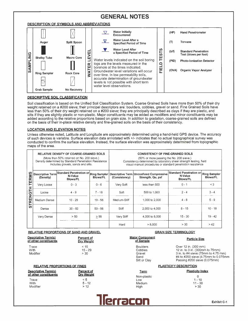
GENERAL NOTES DESCRIPTION OF SYMBOLS AND ABBREVIATIONS
[I] ~ .5L Water Initially (HP) Hand Penetrometer Encountered
Auger Split Spoon ~ Water Level After a (T) Torvane Specified Period of Time
I [I] ...J _y__ Water Level After CJ) (b/f) Standard Penetration
(!) w a Specified Period of Time I-> CJ) Test (blows per foot) z Shelby Tube Macro Core w w
:::i ...J Water levels indicated on the soil boring I- (PIO) Photo-Ionization Detector CL. D [] e::: logs are the levels measured in the c ::! w borehole at the times indicated. ...J <( I- w CJ) <( Groundwater level variations will occur u::: (OVA) Organic Vapor Analyzer
Ring Sampler Rock Core 3: over time. In low permeability soils,
~ 0 accurate determination of groundwater levels is not possible with short term water level observations.
Grab Sample No Recovery
QESCRIPTIVE SOIL CLASSIFICATION
Soil classification is based on the Unified Soil Classification System. Coarse Grained Soils have more than 50% of their dry weight retained on a #200 sieve; their principal descriptors are: boulders, cobbles, gravel or sand . Fine Grained Soils have less than 50% of their dry weight retained on a #200 sieve; they are principally described as clays if they are plastic, and silts if they are slightly plastic or non-plastic. Major constituents may be added as modifiers and minor constituents may be added according to the relative proportions based on grain size. In addition to gradation, coarse-grained soils are defined on the basis of their in-place relative density and fine-grained soils on the basis of their consistency.
LOCATION AND ELEVATION NOTES
Unless otherwise noted, Latitude and Longitude are approximately determined using a hand-held GPS device. The accuracy of such devices is variable. Surface elevation data annotated with +/- indicates that no actual topographical survey was conducted to confirm the surface elevation. Instead, the surface elevation was approximately determined from topographic maps of the area.
RELATIVE DENSITY OF COARSE-GRAINED SOILS (More than 50% retained on No. 200 sieve.)
Density determined by Standard Penetration Resistance Includes gravels, sands and silts.
CJ) Descriptive Term Standard Penetration or Ring Sampler ::! N-Value e::: (Density)
Blows/Ft. Blows/Ft.
w I- Very Loose 0-3 0-6 :I: I- Loose 4 - 9 7 - 18 (!) z w Medium Dense 10 - 29 19 - 58 e::: I-CJ)
Dense 30 - 50 59- 98
Very Dense > 50 .'.".. 99
RELATIVE PROPORTIONS OF SAND AND GRAVEL
Descriptive Term(s) of other constituents
Trace With Modifier
Percent of Orv Weight
< 15 15 - 29 > 30
RELATIVE PROPORTIONS OF FINES
Oescrjptjve Term<s> of other constjtuents
Trace With Modifier
percent of orvWejght
<5 5 - 12 > 12
CONSISTENCY OF FINE-GRAINED SOILS (50% or more passing the No. 200 sieve.)
Consistency determined by laboratory shear strength testing, field visual-manual procedures or standard penetration resistance
Descriptive Term Unconfined Compressive Standard Penetration or Ring Sampler (Consistency) Strength, Qu, psf N-Value Blows/Ft.
Blows/Ft.
Very Soft less than 500 0 - 1 <3
Soft 500 to 1,000 2-4 3 -4
Medium-Stiff 1,000 to 2,000 4-8 5-9
Stiff 2,000 to 4,000 8-15 10-18
Very Stiff 4,000 to 8,000 15 - 30 19-42
Hard > 8,000 > 30 > 42
GRAIN SIZE TERMINOLOGY
Major Component of Sample
Particle Size
Boulders Cobbles Gravel Sand Silt or Clay
Term
Non-plastic Low Medium High
Over 12 in. (300 mm) 12 in. to 3 in . (300mm to 75mm) 3 in . to #4 sieve (75mm to 4.75 mm) #4 to #200 sieve (4 .75mm to 0.075mm Passing #200 sieve (0.075mm)
PLASTICITY DESCRIPTION
Plastjcjtv Index
0 1 - 10
11 - 30 > 30
llerracon Exhibit C-1

UNIFIED SOIL CLASSIFICATION SYSTEM
Well-graded gravel More than 50% of Cu < 4 and/pr 1 > Cc> 3 E GP Poorly graded gravel F
coarse Gravels with Fines: Fines classify as ML or MH GM Silty gravel F,G, H
fraction retained on Coarse Grained Soils: More than 12% fines c Fines classify as CL or CH GC Clayey gravel F,G,H
More than 50% retained No. 4 sieve
on No. 200 sieve Sands: Clean Sands: Cu ~ 6 and 1 ~ Cc ~ 3 E SW Well-graded sand 1
50% or more of coarse Less than 5% fines 0 Cu < 6 and/or 1 > Cc> 3 E SP Poorly graded sand 1
fraction passes Sands with Fines: Fines classify as ML or MH SM Silty sand G,H,i
No. 4 sieve More than 12% fines 0 Fines Classify as CL or CH SC Clayey sand G,H,i
Pl > 7 and plots on or above "A" line J CL Lean clay K,L,M
Silts and Clays: Inorganic:
Pl < 4 or plots below "A" line J ML SiltK,L,M
Liquid limit less than 50 Organic:
Liquid limit - oven dried <0.75 OL
Organic clay K,L,M,N Fine-Grained Soils: Liquid limit - not dried Organic silt K,L,M,o 50% or more passes the
Pl plots on or above "A" line CH Fat clay K,L,M No. 200 sieve Inorganic:
Silts and Clays: Pl plots below "A" line MH Elastic Silt K,L,M
Liquid limit 50 or more Organic:
Liquid limit - oven dried <0.75 OH
Organic clay K,L,M,P
Liquid limit - not dried Organic silt K,L,M,a
Highly organic soils: Primarily organic matter, dark in color, and organic odor PT Peat
A Based on the material passing the 3-in. (75-mm) sieve 8 If field sample contained cobbles or boulders, or both, add "with cobbles
or boulders, or both" to group name. c Gravels with 5 to 12% fines require dual symbols: GW-GM well-graded
gravel with silt, GW-GC well-graded gravel with clay, GP-GM poorly graded gravel with silt, GP-GC poorly graded gravel with clay.
0 Sands with 5 to 12% fines require dual symbols: SW-SM well-graded sand with silt, SW-SC well-graded sand with clay, SP-SM poorly graded sand with silt, SP-SC poorly graded sand with clay
(030 )2 E Cu = D50/D10 Cc = ----
010 x 0 60
F If soil contains~ 15% sand, add "with sand" to group name. G If fines classify as CL-ML, use dual symbol GC-GM, or SC-SM.
-~
60 For classmcatlon of fine-grained soils and fine-grained fraction
50 of coarse-grained soils
(j) 40
Equation of •A" - line Horizontal at Pl=4 to Ll=25.5.
then Pl=0.73 (LL-20)
c ~ ~ 30
C3 ~ 20 1-----+----------
CL.
H If fines are organic, add "with organic fines" to group name. 1 If soil contains~ 15% gravel, add "with gravel" to group name. J If Atterberg limits plot in shaded area, soil is a CL-ML, silty clay. K If soil contains 15 to 29% plus No. 200, add "with sand" or "with
gravel," whichever is predominant. L If soil contains ~ 30% plus No. 200 predominantly sand, add "sandy"
to group name. M If soil contains ~ 30% plus No. 200, predominantly gravel, add
"gravelly" to group name. N Pl ~ 4 and plots on or above "A" line. 0 Pl < 4 or plots below "A" line. P Pl plots on or above "A" line. 0 Pl plots below "A" line.
MH or OH
10~--4c._--..r::----l--,,,£.--+---+---I----+~--+----+---+---~
~ -~·••"1 o~-_..J. _ _.___.__ __ _J_ __ ....J_ __ ~ __ ,__ _ _..J. __ -L. __ ___,_ __ ....J_ __ ~
0 10 16 20 30 40 50 60 70 80 90 100 110
LIQUID LIMIT (LL)
Exhibit C-2

GENERAL NOTES Sedimentary Rock Classification
DESCRIPTIVE ROCK CLASSIFICATION:
LIMESTONE
DOLOMITE
CHERT
SHALE
SANDSTONE
CONGLOMERATE
Sedimentary rocks are composed of cemented clay, silt and sand sized particles. The most common minerals are clay, quartz and calcite. Rock composed primarily of calcite is called limestone; rock of sand size grains is called sandstone, and rock of clay and silt size grains is called mudstone or claystone, siltstone, or shale. Modifiers such as shaly, sandy, dolomitic, calcareous, carbonaceous, etc. are used to describe various constituents. Examples: sandy shale; calcareous sandstone.
Light to dark colored, crystalline to fine-grained texture, composed of CaCo3, reacts readily with HCI.
Light to dark colored, crystalline to fine-grained texture, composed of CaMg(CQ3)2, harder than limestone, reacts with HCI when powdered.
Light to dark co.lored, very fine-grained texture, composed of micro-crystalline quartz (Si02), brittle, breaks into angular fragments, will scratch glass.
Very fine-grained texture, composed of consolidated silt or clay, bedded in thin layers. The unlaminated equivalent is frequently referred to as siltstone, claystone or mudstone.
Usually light colored, coarse to fine texture, composed of cemented sand size grains of quartz, feldspar, etc. Cement usually is silica but may be such minerals as calcite, iron-oxide, or some other carbonate.
Rounded rock fragments of variable mineralogy varying in size from near sand to boulder size but usually pebble to cobble size (1/2 inch to 6 inches). Cemented together with various cementing agents. Breccia is similar but composed of angular, fractured rock particles cemented together.
PHYSICAL PROPERTIES:
DEGREE OF WEATHERING
Slight
Moderate
High
Slight decomposition of parent material on joints. May be color change.
Some decomposition and color change throughout.
Rock highly decomposed, may be extremely broken.
HARDNESS AND DEGREE OF CEMENTATION
Limestone and Dolomite:
Hard Difficult to scratch with knife.
Moderately Hard
Soft
Can be scratched easily with knife, cannot be scratched with fingernail.
Can be scratched with fingernail.
Shale, Siltstone and Claystone
Hard
Moderately Hard
Soft
Can be scratched easily with knife, cannot be scratched with fingernail.
Can be scratched with fingernail.
Can be easily dented but not molded with fingers.
Sandstone and Conglomerate Well Capable of scratching a knife blade. Cemented
Cemented Can be scratched with knife.
Poorly Cemented
Form 110-6·85
Can be broken apart easily with fingers.
BEDDING AND JOINT CHARACTERISTICS
Bed Thickness Very Thick
Thick Medium
Ttiin Very Thin Laminated
Joint Spacing Very Wide
Wide Moderately Close
Close Very Close
Dimensions >10'
3' - 10' 1' - 3' 2" - 1'
.4" - 2"
.1" - .4"
Bedding Plane A plane dividing sedimentary rocks of the same or different lithology.
Joint
Seam
Fracture in rock, generally more or less vertical or transverse to bedding, along which no appreciable movement has occurred.
Generally applies to bedding plane with an unspecified degree of weathering.
SOLUTION AND VOID CONDITIONS
Solid
Vuggy (Pitted)
Porous
Cavernous
Contains no voids.
Rock having small solution pits or cavities tJP to 1/2 inch diameter, frequently with a mineral lining.
Containing numerous voids, pores, or other openings, which may or may not interconnect.
Containing cavities or caverns, sometimes quite large.