geotechnical engineering report terracon project no. 03175303 geotechnical...geotechnical...
TRANSCRIPT
REPORT C OVER PAGE
Geotechnical Engineering Report Main Building Cooling Tower Replacement
Oklahoma City, Oklahoma
December 8, 2017
Terracon Project No. 03175303
Prepared for:
Oklahoma City Community College
Oklahoma City, Oklahoma
Prepared by:
Terracon Consultants, Inc.
Oklahoma City, Oklahoma

Responsive ■ Resourceful ■ Reliable
REPORT TOPICS
REPORT TOPICS
INTRODUCTION ............................................................................................................. 1 SITE CONDITIONS ......................................................................................................... 1
PROJECT DESCRIPTION .............................................................................................. 2 GEOTECHNICAL CHARACTERIZATION ...................................................................... 2 GEOTECHNICAL OVERVIEW ....................................................................................... 3 EARTHWORK ................................................................................................................ 4 DEEP FOUNDATION ...................................................................................................... 6
SEISMIC CONSIDERATIONS ........................................................................................ 7 GENERAL COMMENTS ................................................................................................. 7
Note: This report was originally delivered in a web-based format. Orange Bold text in the report indicates a referenced
section heading. The PDF version also includes hyperlinks which direct the reader to that section and clicking on the
logo will bring you back to this page. For more interactive features, please view your project online at
client.terracon.com.
ATTACHMENTS
EXPLORATION AND TESTING PROCEDURES
SITE LOCATION AND EXPLORATION PLANS
EXPLORATION RESULTS (Boring Logs and Laboratory Data)
SUPPORTING INFORMATION (General Notes and Unified Soil Classification System
and Description of Rock Properties)
Responsive ■ Resourceful ■ Reliable 1
INTRODUCTION
Geotechnical Engineering Report
Main Building Cooling Tower Replacement
7777 South May Avenue
Oklahoma City, Oklahoma Terracon Project No. 03175303
December 8, 2017
INTRODUCTION
This report presents the results of our subsurface exploration and geotechnical engineering
services performed for the proposed Main Building Cooling Tower Replacement to be located at
Oklahoma City Community College at 7777 South May Avenue in Oklahoma City, Oklahoma. The
purpose of these services is to provide information and geotechnical engineering
recommendations relative to:
■ Subsurface soil and rock conditions ■ Foundation design and construction
■ Groundwater conditions ■ Seismic site classification per IBC
■ Site preparation and earthwork
The geotechnical engineering scope of services for this project included the advancement of one
test boring to a depth of approximately 25 feet below existing site grades.
Maps showing the site and boring locations are shown in the Site Location and Exploration
Plan sections, respectively. The results of the laboratory testing performed on soil samples
obtained from the site during the field exploration are included on the boring log in the Exploration
Results section of this report.
SITE CONDITIONS
The following description of site conditions is derived from our site visit in association with the
field exploration and our review of publicly available geologic and topographic maps.
Item Description
Parcel Information
The project is located at the Oklahoma City Community College at 7777
South May Avenue in Oklahoma City, Oklahoma.
See Site Location
Existing
Improvements Existing cooling tower
Geotechnical Engineering Report
Main Building Cooling Tower Replacement ■ Oklahoma City, Oklahoma
December 8, 2017 ■ Terracon Project No. 03175303
Responsive ■ Resourceful ■ Reliable 2
Item Description
Current Ground
Cover Vegetation and existing cooling tower
Existing Topography Relatively flat.
PROJECT DESCRIPTION
Our initial understanding of the project was provided in our proposal and was discussed in the
project planning stage. Our final understanding of the project conditions is as follows:
Item Description
Proposed Structure This project will include replacement of the existing cooling tower with a new 1500 ton cooling tower.
Maximum Loads (provided by Cyntergy)
50,000 lbs.
Grading/Slopes Less than 2 feet of cut and fill will be required to develop final grade.
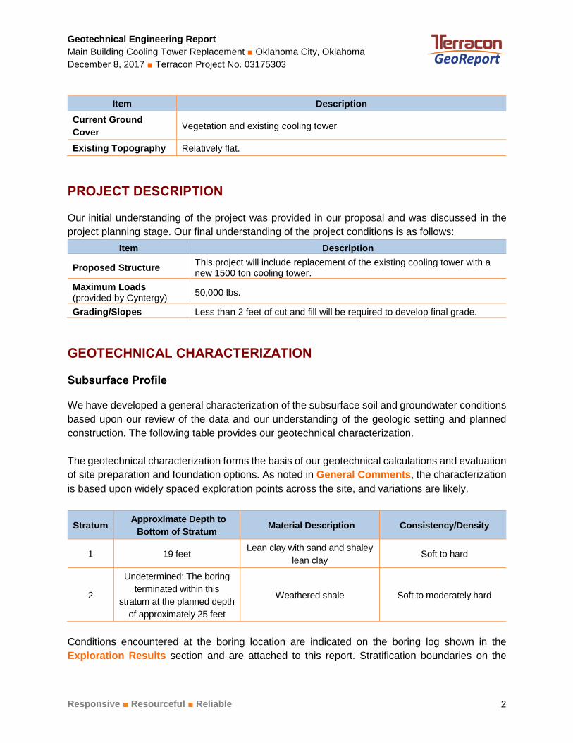
GEOTECHNICAL CHARACTERIZATION
Subsurface Profile
We have developed a general characterization of the subsurface soil and groundwater conditions
based upon our review of the data and our understanding of the geologic setting and planned
construction. The following table provides our geotechnical characterization.
The geotechnical characterization forms the basis of our geotechnical calculations and evaluation
of site preparation and foundation options. As noted in General Comments, the characterization
is based upon widely spaced exploration points across the site, and variations are likely.
Stratum Approximate Depth to
Bottom of Stratum Material Description Consistency/Density
1 19 feet Lean clay with sand and shaley
lean clay Soft to hard
2
Undetermined: The boring
terminated within this
stratum at the planned depth
of approximately 25 feet
Weathered shale Soft to moderately hard
Conditions encountered at the boring location are indicated on the boring log shown in the
Exploration Results section and are attached to this report. Stratification boundaries on the
Geotechnical Engineering Report
Main Building Cooling Tower Replacement ■ Oklahoma City, Oklahoma
December 8, 2017 ■ Terracon Project No. 03175303
Responsive ■ Resourceful ■ Reliable 3
boring log represent the approximate location of changes in native soil types; in situ, the transition
between materials may be gradual.
Groundwater Conditions
The borehole was observed while drilling and after completion for the presence and level of
groundwater. The water levels observed in the borehole can be found on the boring log in
Exploration Results, and are summarized below.
Groundwater was observed in the boring at depths of approximately 7 to 8.5 feet while drilling and
immediately after drilling. However, this does not necessarily mean the water level is a stable
groundwater level. Due to the low permeability of the soils encountered in the boring, a relatively
long period may be necessary for a groundwater level to develop and stabilize in a borehole. Long
term observations in piezometers or observation wells sealed from the influence of surface water are
often required to define groundwater levels in materials of this type.
Groundwater level fluctuations occur due to seasonal variations in the amount of rainfall, runoff
and other factors not evident at the time the borings were performed. Therefore, groundwater
levels during construction or at other times in the life of the structure may be higher or lower than
the levels indicated on the boring logs. The possibility of groundwater level fluctuations should be
considered when developing the design and construction plans for the project.
GEOTECHNICAL OVERVIEW
The boring generally encountered lean clays and shaley lean clays extending to a depth of
approximately 19 feet. Soft, wet clay was encountered in the boring at a depth of about 6 feet.
The overburden soils were underlain by weathered shale to the boring termination depth at
approximately 25 feet.
Site preparation recommendations including subgrade improvement and fill placement are
provided in the Earthwork section.
Based on the subsurface conditions encountered, we recommend a drilled pier foundation system
bearing in the weathered shale be used to support the proposed cooling tower. The Deep
Foundation section address the support of the cooling tower.
The General Comments section provides an understanding of the report limitations.
Geotechnical Engineering Report
Main Building Cooling Tower Replacement ■ Oklahoma City, Oklahoma
December 8, 2017 ■ Terracon Project No. 03175303
Responsive ■ Resourceful ■ Reliable 4
EARTHWORK
The following sections provide recommendations for use in the preparation of specifications for
the work. Recommendations include critical quality criteria as necessary to render the site in the
state considered in our geotechnical engineering evaluation for foundations.
Site Preparation
Site preparation should include removing the vegetation, topsoil, remaining foundations, and any
other unsuitable surface materials from the areas of new construction. The depressions or
excavations created during demolition of the existing cooling tower should be cleaned of loose
material and backfilled as outlined in the following paragraphs. Actual removal depths should be
determined at the time of construction by a representative of the geotechnical engineer.
After site stripping, but before placing any fill, we recommend the exposed soils be proofrolled
with a loaded, tandem-axle dump truck weighing at least 25 tons (under the observation of
Terracon personnel) to locate any soft or unstable zones. The proofrolling should involve
overlapping passes in mutually perpendicular directions. Where rutting or pumping is observed
during proofrolling, the unstable soils should be overexcavated and replaced with an approved
low volume change soil as described in the following sections if it cannot be effectively compacted
in-place.
After a successful proofroll, we recommend scarifying the exposed subgrade soils to a minimum
depth of 8 inches. The scarified soil should be adjusted to a workable moisture content that is at
or above its optimum value, as determined by test method ASTM D-698 (standard Proctor), prior
to being compacted to at least 95 percent of its maximum dry density.
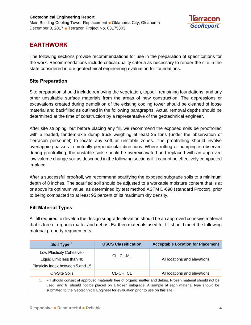
Fill Material Types
All fill required to develop the design subgrade elevation should be an approved cohesive material
that is free of organic matter and debris. Earthen materials used for fill should meet the following
material property requirements:
Soil Type 1 USCS Classification Acceptable Location for Placement
Low Plasticity Cohesive -
Liquid Limit less than 40
Plasticity index between 5 and 15
CL, CL-ML
All locations and elevations
On-Site Soils CL-CH, CL All locations and elevations
1. Fill should consist of approved materials free of organic matter and debris. Frozen material should not be
used, and fill should not be placed on a frozen subgrade. A sample of each material type should be
submitted to the Geotechnical Engineer for evaluation prior to use on this site.
Geotechnical Engineering Report
Main Building Cooling Tower Replacement ■ Oklahoma City, Oklahoma
December 8, 2017 ■ Terracon Project No. 03175303
Responsive ■ Resourceful ■ Reliable 5
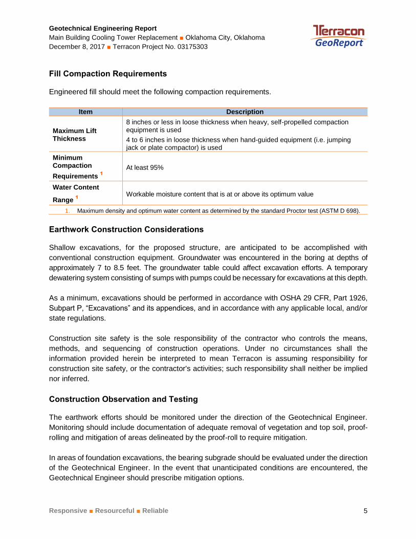
Fill Compaction Requirements
Engineered fill should meet the following compaction requirements.
Item Description
Maximum Lift Thickness
8 inches or less in loose thickness when heavy, self-propelled compaction equipment is used
4 to 6 inches in loose thickness when hand-guided equipment (i.e. jumping jack or plate compactor) is used
Minimum Compaction
Requirements 1
At least 95%
Water Content
Range 1
Workable moisture content that is at or above its optimum value
1. Maximum density and optimum water content as determined by the standard Proctor test (ASTM D 698).
Earthwork Construction Considerations
Shallow excavations, for the proposed structure, are anticipated to be accomplished with
conventional construction equipment. Groundwater was encountered in the boring at depths of
approximately 7 to 8.5 feet. The groundwater table could affect excavation efforts. A temporary
dewatering system consisting of sumps with pumps could be necessary for excavations at this depth.
As a minimum, excavations should be performed in accordance with OSHA 29 CFR, Part 1926,
Subpart P, “Excavations” and its appendices, and in accordance with any applicable local, and/or
state regulations.
Construction site safety is the sole responsibility of the contractor who controls the means,
methods, and sequencing of construction operations. Under no circumstances shall the
information provided herein be interpreted to mean Terracon is assuming responsibility for
construction site safety, or the contractor's activities; such responsibility shall neither be implied
nor inferred.
Construction Observation and Testing
The earthwork efforts should be monitored under the direction of the Geotechnical Engineer.
Monitoring should include documentation of adequate removal of vegetation and top soil, proof-
rolling and mitigation of areas delineated by the proof-roll to require mitigation.
In areas of foundation excavations, the bearing subgrade should be evaluated under the direction
of the Geotechnical Engineer. In the event that unanticipated conditions are encountered, the
Geotechnical Engineer should prescribe mitigation options.
Geotechnical Engineering Report
Main Building Cooling Tower Replacement ■ Oklahoma City, Oklahoma
December 8, 2017 ■ Terracon Project No. 03175303
Responsive ■ Resourceful ■ Reliable 6
In addition to the documentation of the essential parameters necessary for construction, the
continuation of the Geotechnical Engineer into the construction phase of the project provides the
continuity to maintain the Geotechnical Engineer’s evaluation of subsurface conditions, including
assessing variations and associated design changes.
DEEP FOUNDATION
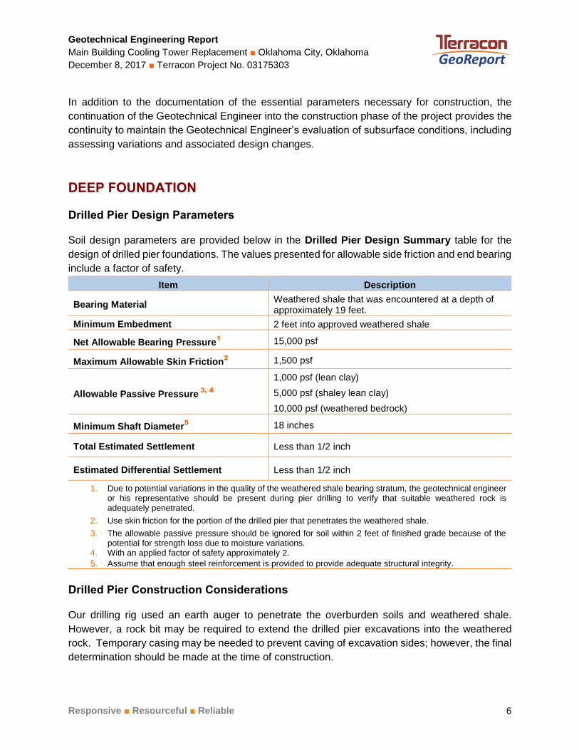
Drilled Pier Design Parameters
Soil design parameters are provided below in the Drilled Pier Design Summary table for the
design of drilled pier foundations. The values presented for allowable side friction and end bearing
include a factor of safety.
Item Description
Bearing Material Weathered shale that was encountered at a depth of approximately 19 feet.
Minimum Embedment 2 feet into approved weathered shale
Net Allowable Bearing Pressure1 15,000 psf
Maximum Allowable Skin Friction2 1,500 psf
Allowable Passive Pressure 3, 4
1,000 psf (lean clay)
5,000 psf (shaley lean clay)
10,000 psf (weathered bedrock)
Minimum Shaft Diameter5 18 inches
Total Estimated Settlement Less than 1/2 inch
Estimated Differential Settlement Less than 1/2 inch
1. Due to potential variations in the quality of the weathered shale bearing stratum, the geotechnical engineeror his representative should be present during pier drilling to verify that suitable weathered rock isadequately penetrated.
2. Use skin friction for the portion of the drilled pier that penetrates the weathered shale.
3. The allowable passive pressure should be ignored for soil within 2 feet of finished grade because of thepotential for strength loss due to moisture variations.
4. With an applied factor of safety approximately 2.
5. Assume that enough steel reinforcement is provided to provide adequate structural integrity.
Drilled Pier Construction Considerations
Our drilling rig used an earth auger to penetrate the overburden soils and weathered shale.
However, a rock bit may be required to extend the drilled pier excavations into the weathered
rock. Temporary casing may be needed to prevent caving of excavation sides; however, the final
determination should be made at the time of construction.
Geotechnical Engineering Report
Main Building Cooling Tower Replacement ■ Oklahoma City, Oklahoma
December 8, 2017 ■ Terracon Project No. 03175303
Responsive ■ Resourceful ■ Reliable 7
Groundwater was encountered in the boring during the field exploration at depths of about 7 to
8.5 feet. Therefore, we anticipate dewatering will be needed for this project. However, the need
for dewatering will depend on the actual groundwater conditions at the time of construction. The
bottom of the pier excavation should be cleaned of debris, loose or disturbed soil, and water if
any prior to placing reinforcing steel and concrete. If water is encountered and cannot be
removed, the concrete should be placed using a tremie pipe and placed from the bottom of the
pier excavation to the top, displacing the water to the surface. Concrete should be placed as
soon as possible after the foundation excavation is completed to reduce the potential for
disturbance of the bearing surface. To facilitate pier construction, concrete should be on-site and
ready for placement as pier excavations are completed. In no event should the pier excavation
be allowed to remain open overnight.
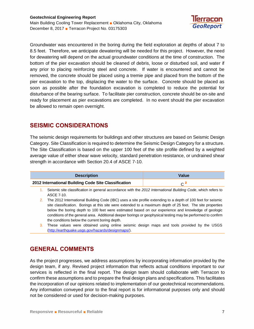
SEISMIC CONSIDERATIONS
The seismic design requirements for buildings and other structures are based on Seismic Design
Category. Site Classification is required to determine the Seismic Design Category for a structure.
The Site Classification is based on the upper 100 feet of the site profile defined by a weighted
average value of either shear wave velocity, standard penetration resistance, or undrained shear
strength in accordance with Section 20.4 of ASCE 7-10.
Description Value
2012 International Building Code Site Classification
(IBC) 1
C 2
1. Seismic site classification in general accordance with the 2012 International Building Code, which refers to
ASCE 7-10.
2. The 2012 International Building Code (IBC) uses a site profile extending to a depth of 100 feet for seismic
site classification. Borings at this site were extended to a maximum depth of 25 feet. The site properties
below the boring depth to 100 feet were estimated based on our experience and knowledge of geologic
conditions of the general area. Additional deeper borings or geophysical testing may be performed to confirm
the conditions below the current boring depth. 3. These values were obtained using online seismic design maps and tools provided by the USGS
(http://earthquake.usgs.gov/hazards/designmaps/).
GENERAL COMMENTS
As the project progresses, we address assumptions by incorporating information provided by the
design team, if any. Revised project information that reflects actual conditions important to our
services is reflected in the final report. The design team should collaborate with Terracon to
confirm these assumptions and to prepare the final design plans and specifications. This facilitates
the incorporation of our opinions related to implementation of our geotechnical recommendations.
Any information conveyed prior to the final report is for informational purposes only and should
not be considered or used for decision-making purposes.
Geotechnical Engineering Report
Main Building Cooling Tower Replacement ■ Oklahoma City, Oklahoma
December 8, 2017 ■ Terracon Project No. 03175303
Responsive ■ Resourceful ■ Reliable 8
Our analysis and opinions are based upon our understanding of the project, the geotechnical
conditions in the area, and the data obtained from our site exploration. Natural variations will occur
between exploration point locations or due to the modifying effects of construction or weather.
The nature and extent of such variations may not become evident until during or after construction.
Terracon should be retained as the Geotechnical Engineer, where noted in the final report, to
provide observation and testing services during pertinent construction phases. If variations
appear, we can provide further evaluation and supplemental recommendations. If variations are
noted in the absence of our observation and testing services on-site, we should be immediately
notified so that we can provide evaluation and supplemental recommendations.
Our scope of services does not include either specifically or by implication any environmental or
biological (e.g., mold, fungi, bacteria) assessment of the site or identification or prevention of
pollutants, hazardous materials or conditions. If the owner is concerned about the potential for
such contamination or pollution, other studies should be undertaken.
Our services and any correspondence or collaboration through this system are intended for the
sole benefit and exclusive use of our client for specific application to the project discussed and
are accomplished in accordance with generally accepted geotechnical engineering practices with
no third party beneficiaries intended. Any third party access to services or correspondence is
solely for information purposes to support the services provided by Terracon to our client. Reliance
upon the services and any work product is limited to our client, and is not intended for third parties.
Any use or reliance of the provided information by third parties is done solely at their own risk. No
warranties, either express or implied, are intended or made.
Site characteristics as provided are for design purposes and not to estimate excavation cost. Any
use of our report in that regard is done at the sole risk of the excavating cost estimator as there
may be variations on the site that are not apparent in the data that could significantly impact
excavation cost. Any parties charged with estimating excavation costs should seek their own site
characterization for specific purposes to obtain the specific level of detail necessary for costing.
Site safety, and cost estimating including, excavation support, and dewatering
requirements/design are the responsibility of others. If changes in the nature, design, or location
of the project are planned, our conclusions and recommendations shall not be considered valid
unless we review the changes and either verify or modify our conclusions in writing.

ATTACHM ENTS
ATTACHMENTS
Geotechnical Engineering Report
Main Building Cooling Tower Replacement ■ Oklahoma City, Oklahoma
December 8, 2017 ■ Terracon Project No. 03175303
Responsive ■ Resourceful ■ Reliable
EXPLORATION AND TESTING PROCEDURES
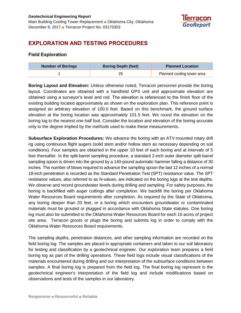
Field Exploration
Number of Borings Boring Depth (feet) Planned Location
1 25 Planned cooling tower area
Boring Layout and Elevation: Unless otherwise noted, Terracon personnel provide the boring
layout. Coordinates are obtained with a handheld GPS unit and approximate elevation are
obtained using a surveyor’s level and rod. The elevation is referenced to the finish floor of the
existing building located approximately as shown on the exploration plan. This reference point is
assigned an arbitrary elevation of 100.0 feet. Based on this benchmark, the ground surface
elevation at the boring location was approximately 101.5 feet. We round the elevation on the
boring log to the nearest one-half foot. Consider the location and elevation of the boring accurate
only to the degree implied by the methods used to make these measurements.
Subsurface Exploration Procedures: We advance the boring with an ATV-mounted rotary drill
rig using continuous flight augers (solid stem and/or hollow stem as necessary depending on soil
conditions). Four samples are obtained in the upper 10 feet of each boring and at intervals of 5
feet thereafter. In the split-barrel sampling procedure, a standard 2-inch outer diameter split-barrel
sampling spoon is driven into the ground by a 140-pound automatic hammer falling a distance of 30
inches. The number of blows required to advance the sampling spoon the last 12 inches of a normal
18-inch penetration is recorded as the Standard Penetration Test (SPT) resistance value. The SPT
resistance values, also referred to as N-values, are indicated on the boring logs at the test depths.
We observe and record groundwater levels during drilling and sampling. For safety purposes, the
boring is backfilled with auger cuttings after completion. We backfill the boring per Oklahoma
Water Resources Board requirements after completion. As required by the State of Oklahoma,
any boring deeper than 20 feet, or a boring which encounters groundwater or contaminated
materials must be grouted or plugged in accordance with Oklahoma State statutes. One boring
log must also be submitted to the Oklahoma Water Resources Board for each 10 acres of project
site area. Terracon grouts or plugs the boring and submits log in order to comply with the
Oklahoma Water Resources Board requirements.
The sampling depths, penetration distances, and other sampling information are recorded on the
field boring log. The samples are placed in appropriate containers and taken to our soil laboratory
for testing and classification by a geotechnical engineer. Our exploration team prepares a field
boring log as part of the drilling operations. These field logs include visual classifications of the
materials encountered during drilling and our interpretation of the subsurface conditions between
samples. A final boring log is prepared from the field log. The final boring log represent is the
geotechnical engineer's interpretation of the field log and include modifications based on
observations and tests of the samples in our laboratory.
Geotechnical Engineering Report
Main Building Cooling Tower Replacement ■ Oklahoma City, Oklahoma
December 8, 2017 ■ Terracon Project No. 03175303
Responsive ■ Resourceful ■ Reliable
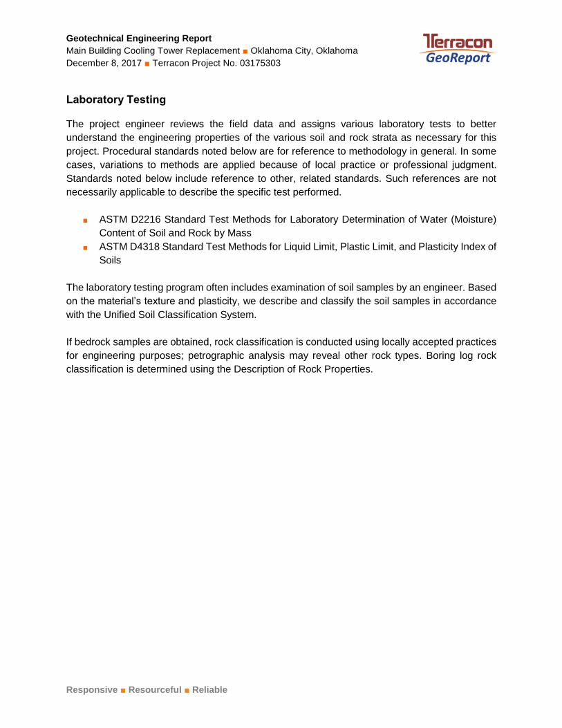
Laboratory Testing
The project engineer reviews the field data and assigns various laboratory tests to better
understand the engineering properties of the various soil and rock strata as necessary for this
project. Procedural standards noted below are for reference to methodology in general. In some
cases, variations to methods are applied because of local practice or professional judgment.
Standards noted below include reference to other, related standards. Such references are not
necessarily applicable to describe the specific test performed.
■ ASTM D2216 Standard Test Methods for Laboratory Determination of Water (Moisture)
Content of Soil and Rock by Mass
■ ASTM D4318 Standard Test Methods for Liquid Limit, Plastic Limit, and Plasticity Index of
Soils
The laboratory testing program often includes examination of soil samples by an engineer. Based
on the material’s texture and plasticity, we describe and classify the soil samples in accordance
with the Unified Soil Classification System.
If bedrock samples are obtained, rock classification is conducted using locally accepted practices
for engineering purposes; petrographic analysis may reveal other rock types. Boring log rock
classification is determined using the Description of Rock Properties.
SITE LOC ATION AND EXPLOR ATION PLAN S
SITE LOCATION AND EXPLORATION PLANS
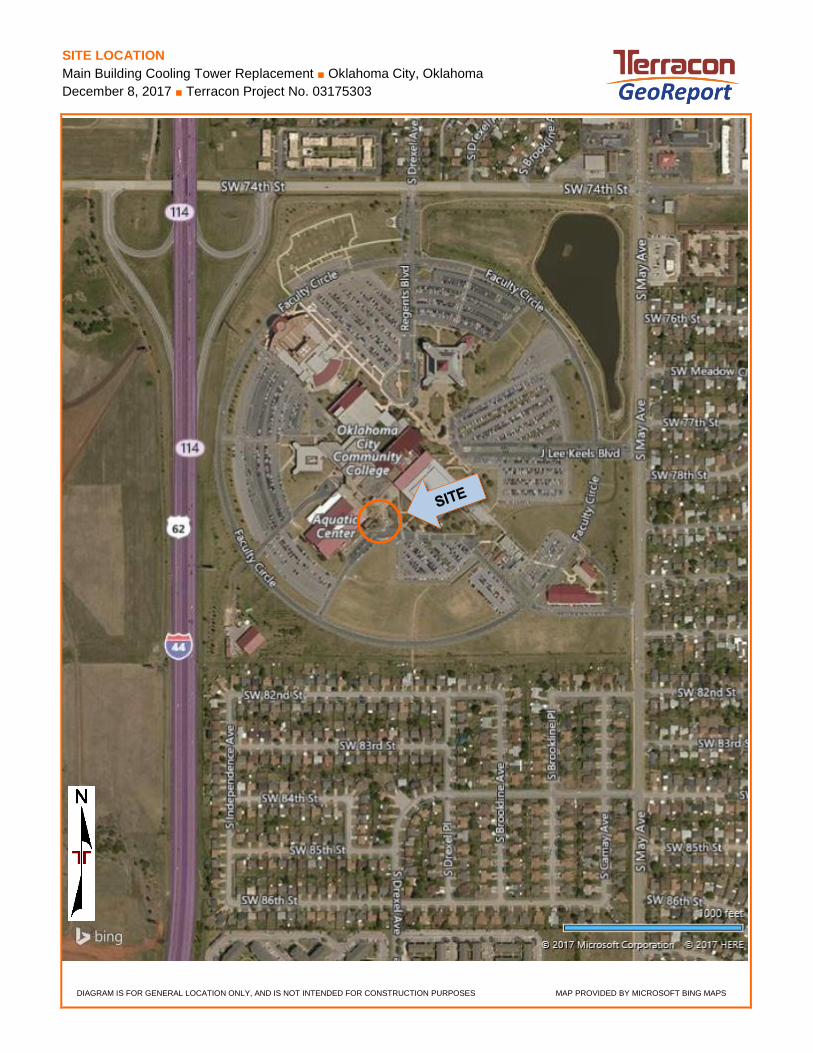
SITE LOCATION
Main Building Cooling Tower Replacement ■ Oklahoma City, Oklahoma
December 8, 2017 ■ Terracon Project No. 03175303
SITE LOC ATION PLAN
DIAGRAM IS FOR GENERAL LOCATION ONLY, AND IS NOT INTENDED FOR CONSTRUCTION PURPOSES MAP PROVIDED BY MICROSOFT BING MAPS
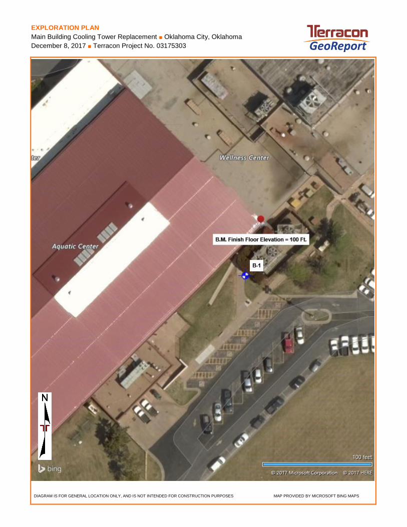
EXPLORATION PLAN
Main Building Cooling Tower Replacement ■ Oklahoma City, Oklahoma
December 8, 2017 ■ Terracon Project No. 03175303
EXPLOR ATION PLAN
DIAGRAM IS FOR GENERAL LOCATION ONLY, AND IS NOT INTENDED FOR CONSTRUCTION PURPOSES MAP PROVIDED BY MICROSOFT BING MAPS
EXPLOR ATION RESULTS
EXPLORATION RESULTS
Vegetation at Surface
21
18
19
15
17
15
24
42-15-27
88.5+/-
82.5+/-
76.5+/-
3-4-7N=11
6-6-8N=14
1-1-1N=2
3-4-4N=8
24-24-30N=54
35-50/3"
15-30-50/6"
14
17
12
17
17
9
16
13.0
19.0
25.0
LEAN CLAY WITH SAND (CL), dark brown, stiff
-brown below 3.5'
-trace gravel, soft below 6'
-reddish-brown, stiff below 8.5'
SHALEY LEAN CLAY (CL), reddish-brown, hard
+WEATHERED SHALE, reddish-brown, moderatelyhard
-soft below 23.5'
Boring Terminated at 25 Feet
Hammer Type: AutomaticStratification lines are approximate. In-situ, the transition may be gradual.+Classification estimated from disturbed samples. Core samples and petrographic analysis mayreveal other rock types.
GR
AP
HIC
LO
G
TH
IS B
OR
ING
LO
G IS
NO
T V
ALI
D IF
SE
PA
RA
TE
D F
RO
M O
RIG
INA
L R
EP
OR
T.
GE
O S
MA
RT
LO
G-N
O W
ELL
_OLD
031
753
03 M
AIN
BU
ILD
ING
CO
O.G
PJ
TE
RR
AC
ON
_DA
TA
TE
MP
LAT
E.G
DT
12/
8/1
7
Page 1 of 1
Advancement Method:Power Auger
Abandonment Method:Boring backfilled with cuttings above 4’; grouted 4’ to 14’;backfilled with cuttings from 14’ to termination depth.
4701 N Stiles AveOklahoma City, OK
Notes:
Project No.: 03175303
Drill Rig: 880
Boring Started: 11-24-2017
BORING LOG NO. B-1Oklahoma City Community CollegeCLIENT:Oklahoma City, Oklahoma
Driller: R. Smalley
Boring Completed: 11-24-2017
PROJECT: Main Building Cooling Tower Replacement
See Exploration and Testing Procedures for adescription of field and laboratory procedures usedand additional data (If any).
See Supporting Information for explanation ofsymbols and abbreviations.
7777 South May Avenue Oklahoma City, OklahomaSITE:
WATER LEVEL OBSERVATIONS
7 ft After boring
8.5 ft While drilling
LAB
OR
AT
OR
YT
OR
VA
NE
/HP
(ps
f)
UN
CO
NF
INE
DC
OM
PR
ES
SIV
ES
TR
EN
GT
H (
psf)
PE
RC
EN
T F
INE
S
WA
TE
RC
ON
TE
NT
(%
)
DR
Y U
NIT
WE
IGH
T (
pcf)
ATTERBERGLIMITS
LL-PL-PI
ELEVATION (Ft.)
Approximate Surface Elev: 101.5 (Ft.) +/-
SA
MP
LE T
YP
E
WA
TE
R L
EV
EL
OB
SE
RV
AT
ION
S
DE
PT
H (
Ft.)
5
10
15
20
25
FIE
LD T
ES
TR
ES
ULT
S
RE
CO
VE
RY
(In
.)
DEPTH
See Exploration PlanLOCATION
Latitude: 35.3864° Longitude: -97.5708°

SUPPORTING INFORM ATION
SUPPORTING INFORMATION
Main Building Cooling Tower Replacement Oklahoma City, Oklahoma
12/8/2017 Terracon Project No. 03175303
500 to 1,000
> 8,000
4,000 to 8,000
2,000 to 4,000
1,000 to 2,000
less than 500
Unconfined Compressive StrengthQu, (psf)
StandardPenetrationTest
Trace
PLASTICITY DESCRIPTION
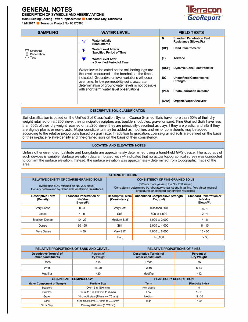
Water levels indicated on the soil boring logs arethe levels measured in the borehole at the timesindicated. Groundwater level variations will occurover time. In low permeability soils, accuratedetermination of groundwater levels is not possiblewith short term water level observations.
DESCRIPTION OF SYMBOLS AND ABBREVIATIONSGENERAL NOTES
> 30
11 - 30
1 - 10Low
Non-plastic
Plasticity Index
#4 to #200 sieve (4.75mm to 0.075mm
Boulders
12 in. to 3 in. (300mm to 75mm)Cobbles
3 in. to #4 sieve (75mm to 4.75 mm)Gravel
Sand
Passing #200 sieve (0.075mm)Silt or Clay
Particle Size
Water Level Aftera Specified Period of Time
Water Level After aSpecified Period of Time
Water InitiallyEncountered
Soil classification is based on the Unified Soil Classification System. Coarse Grained Soils have more than 50% of their dryweight retained on a #200 sieve; their principal descriptors are: boulders, cobbles, gravel or sand. Fine Grained Soils have lessthan 50% of their dry weight retained on a #200 sieve; they are principally described as clays if they are plastic, and silts if theyare slightly plastic or non-plastic. Major constituents may be added as modifiers and minor constituents may be addedaccording to the relative proportions based on grain size. In addition to gradation, coarse-grained soils are defined on the basisof their in-place relative density and fine-grained soils on the basis of their consistency.
GRAIN SIZE TERMINOLOGY
RELATIVE PROPORTIONS OF FINESRELATIVE PROPORTIONS OF SAND AND GRAVEL
DESCRIPTIVE SOIL CLASSIFICATION
LOCATION AND ELEVATION NOTES
SAMPLING WATER LEVEL FIELD TESTSN
(HP)
(T)
(DCP)
UC
(PID)
(OVA)
Standard Penetration TestResistance (Blows/Ft.)
Hand Penetrometer
Torvane
Dynamic Cone Penetrometer
Unconfined CompressiveStrength
Photo-Ionization Detector
Organic Vapor Analyzer
Medium
0Over 12 in. (300 mm)
>12
5-12
<5
Percent ofDry Weight
TermMajor Component of Sample
Modifier
With
Trace
Descriptive Term(s) ofother constituents
>30Modifier
<15
Percent ofDry Weight
Descriptive Term(s) ofother constituents
With 15-29
High
Unless otherwise noted, Latitude and Longitude are approximately determined using a hand-held GPS device. The accuracy ofsuch devices is variable. Surface elevation data annotated with +/- indicates that no actual topographical survey was conductedto confirm the surface elevation. Instead, the surface elevation was approximately determined from topographic maps of thearea.
Standard Penetration orN-Value
Blows/Ft.
Descriptive Term(Density)
CONSISTENCY OF FINE-GRAINED SOILS
Hard
15 - 30Very Stiff> 50Very Dense
8 - 15Stiff30 - 50Dense
4 - 8Medium Stiff10 - 29Medium Dense
2 - 4Soft4 - 9Loose
0 - 1Very Soft0 - 3Very Loose
(50% or more passing the No. 200 sieve.)Consistency determined by laboratory shear strength testing, field visual-manual
procedures or standard penetration resistance
STRENGTH TERMS
> 30
Descriptive Term(Consistency)
Standard Penetration orN-Value
Blows/Ft.
RELATIVE DENSITY OF COARSE-GRAINED SOILS
(More than 50% retained on No. 200 sieve.)Density determined by Standard Penetration Resistance
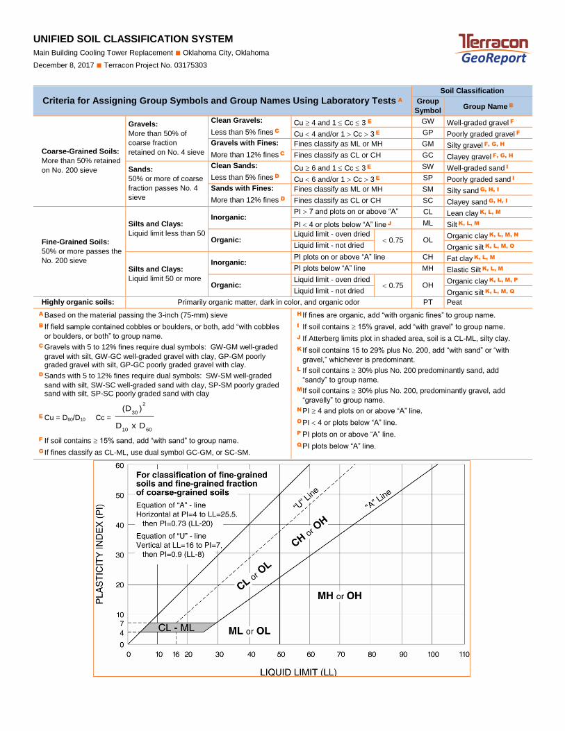
UNIFIED SOIL CLASSIFICATION SYSTEM
Main Building Cooling Tower Replacement ■ Oklahoma City, Oklahoma
December 8, 2017 ■ Terracon Project No. 03175303
UNIFIED SOIL C LASSIFIC AT ION SYSTEM
Criteria for Assigning Group Symbols and Group Names Using Laboratory Tests A Soil Classification
Group
Symbol Group Name B
Coarse-Grained Soils:
More than 50% retained
on No. 200 sieve
Gravels:
More than 50% of
coarse fraction
retained on No. 4 sieve
Clean Gravels:
Less than 5% fines C
Cu 4 and 1 Cc 3 E GW Well-graded gravel F
Cu 4 and/or 1 Cc 3 E GP Poorly graded gravel F
Gravels with Fines:
More than 12% fines C
Fines classify as ML or MH GM Silty gravel F, G, H
Fines classify as CL or CH GC Clayey gravel F, G, H
Sands:
50% or more of coarse
fraction passes No. 4
sieve
Clean Sands:
Less than 5% fines D
Cu 6 and 1 Cc 3 E SW Well-graded sand I
Cu 6 and/or 1 Cc 3 E SP Poorly graded sand I
Sands with Fines:
More than 12% fines D
Fines classify as ML or MH SM Silty sand G, H, I
Fines classify as CL or CH SC Clayey sand G, H, I
Fine-Grained Soils:
50% or more passes the
No. 200 sieve
Silts and Clays:
Liquid limit less than 50
Inorganic: PI 7 and plots on or above “A”
line J
CL Lean clay K, L, M
PI 4 or plots below “A” line J ML Silt K, L, M
Organic: Liquid limit - oven dried
0.75 OL Organic clay K, L, M, N
Liquid limit - not dried Organic silt K, L, M, O
Silts and Clays:
Liquid limit 50 or more
Inorganic: PI plots on or above “A” line CH Fat clay K, L, M
PI plots below “A” line MH Elastic Silt K, L, M
Organic: Liquid limit - oven dried
0.75 OH Organic clay K, L, M, P
Liquid limit - not dried Organic silt K, L, M, Q
Highly organic soils: Primarily organic matter, dark in color, and organic odor PT Peat
A Based on the material passing the 3-inch (75-mm) sieve
B If field sample contained cobbles or boulders, or both, add “with cobbles
or boulders, or both” to group name.
C Gravels with 5 to 12% fines require dual symbols: GW-GM well-graded
gravel with silt, GW-GC well-graded gravel with clay, GP-GM poorly graded gravel with silt, GP-GC poorly graded gravel with clay.
D Sands with 5 to 12% fines require dual symbols: SW-SM well-graded
sand with silt, SW-SC well-graded sand with clay, SP-SM poorly graded sand with silt, SP-SC poorly graded sand with clay
E Cu = D60/D10 Cc =
6010
2
30
DxD
)(D
F If soil contains 15% sand, add “with sand” to group name.
G If fines classify as CL-ML, use dual symbol GC-GM, or SC-SM.
H If fines are organic, add “with organic fines” to group name.
I If soil contains 15% gravel, add “with gravel” to group name.
J If Atterberg limits plot in shaded area, soil is a CL-ML, silty clay.
K If soil contains 15 to 29% plus No. 200, add “with sand” or “with
gravel,” whichever is predominant.
L If soil contains 30% plus No. 200 predominantly sand, add
“sandy” to group name.
M If soil contains 30% plus No. 200, predominantly gravel, add
“gravelly” to group name.
N PI 4 and plots on or above “A” line.
O PI 4 or plots below “A” line.
P PI plots on or above “A” line.
Q PI plots below “A” line.
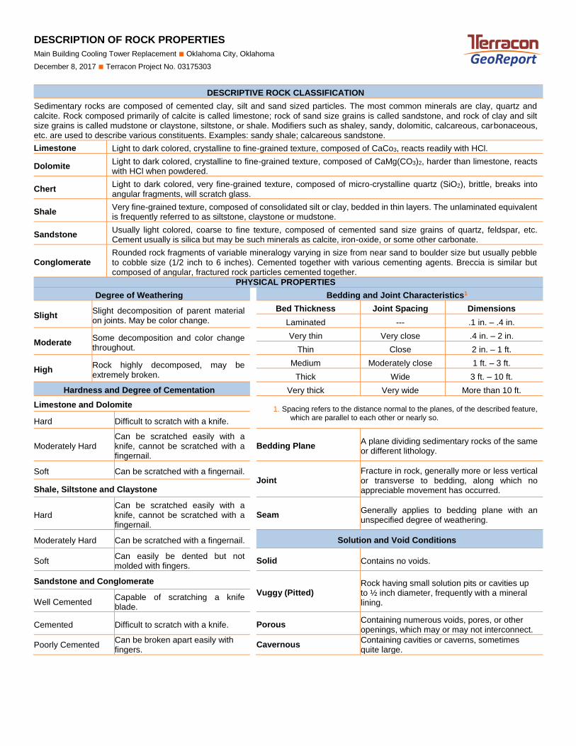
DESCRIPTION OF ROCK PROPERTIES
Main Building Cooling Tower Replacement ■ Oklahoma City, Oklahoma
December 8, 2017 ■ Terracon Project No. 03175303
ROCK VER SION 2
DESCRIPTIVE ROCK CLASSIFICATION
Sedimentary rocks are composed of cemented clay, silt and sand sized particles. The most common minerals are clay, quartz and calcite. Rock composed primarily of calcite is called limestone; rock of sand size grains is called sandstone, and rock of clay and silt size grains is called mudstone or claystone, siltstone, or shale. Modifiers such as shaley, sandy, dolomitic, calcareous, carbonaceous, etc. are used to describe various constituents. Examples: sandy shale; calcareous sandstone.
Limestone Light to dark colored, crystalline to fine-grained texture, composed of CaCo3, reacts readily with HCl.
Dolomite Light to dark colored, crystalline to fine-grained texture, composed of CaMg(CO3)2, harder than limestone, reacts with HCl when powdered.
Chert Light to dark colored, very fine-grained texture, composed of micro-crystalline quartz (SiO2), brittle, breaks into angular fragments, will scratch glass.
Shale Very fine-grained texture, composed of consolidated silt or clay, bedded in thin layers. The unlaminated equivalent is frequently referred to as siltstone, claystone or mudstone.
Sandstone Usually light colored, coarse to fine texture, composed of cemented sand size grains of quartz, feldspar, etc. Cement usually is silica but may be such minerals as calcite, iron-oxide, or some other carbonate.
Conglomerate Rounded rock fragments of variable mineralogy varying in size from near sand to boulder size but usually pebble to cobble size (1/2 inch to 6 inches). Cemented together with various cementing agents. Breccia is similar but composed of angular, fractured rock particles cemented together.
PHYSICAL PROPERTIES
Degree of Weathering Bedding and Joint Characteristics1
Slight Slight decomposition of parent material on joints. May be color change.
Bed Thickness Joint Spacing Dimensions
Laminated --- .1 in. – .4 in.
Moderate Some decomposition and color change throughout.
Very thin Very close .4 in. – 2 in.
Thin Close 2 in. – 1 ft.
High Rock highly decomposed, may be extremely broken.
Medium Moderately close 1 ft. – 3 ft.
Thick Wide 3 ft. – 10 ft.
Hardness and Degree of Cementation
Very thick Very wide More than 10 ft.
Limestone and Dolomite 1. Spacing refers to the distance normal to the planes, of the described feature,
which are parallel to each other or nearly so. Hard Difficult to scratch with a knife.
Moderately Hard Can be scratched easily with a knife, cannot be scratched with a fingernail.
Bedding Plane A plane dividing sedimentary rocks of the same or different lithology.
Soft Can be scratched with a fingernail. Joint
Fracture in rock, generally more or less vertical or transverse to bedding, along which no appreciable movement has occurred. Shale, Siltstone and Claystone
Hard Can be scratched easily with a knife, cannot be scratched with a fingernail.
Seam Generally applies to bedding plane with an unspecified degree of weathering.
Moderately Hard Can be scratched with a fingernail. Solution and Void Conditions
Soft Can easily be dented but not molded with fingers.
Solid Contains no voids.
Sandstone and Conglomerate
Vuggy (Pitted) Rock having small solution pits or cavities up to ½ inch diameter, frequently with a mineral lining. Well Cemented
Capable of scratching a knife blade.
Cemented Difficult to scratch with a knife. Porous Containing numerous voids, pores, or other openings, which may or may not interconnect.
Poorly Cemented Can be broken apart easily with fingers.
Cavernous Containing cavities or caverns, sometimes quite large.