geosynthetics as a component of sustainability in pavement
TRANSCRIPT
Geosynthetics as a Component of Sustainability in Pavement Structure Design for Arterial Roadways
Brian Morrison, P.Eng. ISL Engineering and Land Services
Paper prepared for presentation at the
Pavements, Innovative Developments in Sustainable Pavements Session
of the 2011 Annual Conference of the Transportation Association of Canada
Edmonton, Alberta

Table of Contents
Abstract 1
1.0 Introduction 2
1.1 Description 2
1.2 Background 3
2.0 Materials and Pavement Design 4
2.1 Traffic Loading Analysis 4
2.2 Geotechnical Data 5
2.3 Design Structures 5
3.0 Life Cycle Cost Analysis 8
4.0 Environmental Considerations 9
5.0 Conclusion 10
6.0 References 11

1
Abstract
Geotextiles and Geogrids are two specific families of Geosynthetics and are discussed in the context of pavement structure design in this paper. Geotextiles materials perform five major functions: separation, reinforcement, filtration, drainage and containment.
1 Geogrids function almost exclusively as
reinforcement materials. In pavement structures, geogrids are generally cost competitive against the granular material they replace, either through lower initial cost or through extended service life of the pavement structure. This paper examines a means to compare traditional pavement structure designs, absent of geosynthetics, to pavement structure designs incorporating geosynthetics. Firstly, a specific road structure design is presented with corresponding traditional road structure components recommended. The road structure is then re-examined incorporating newly developed, re-engineered geogrid. Benefits of incorporating geotextile fabrics into the pavement structure as a material separator and drainage medium are examined. Secondly, costs associated with this particular design are outlined, analyzed and compared. In this case, cost savings achieved by using geogrid are substantial. These savings are realized by the reduction of several thousand cubic meters (m3) of granular base course and decreased excavation costs.
Finally, keeping in mind the context of the 2011 TAC Conference theme, “Transportation Successes: Let’s Build on Them”, this paper highlights how the engineering industry is addressing sustainability issues in the field of pavement structure design. Materials associated with geosynthetics are largely environmentally sustainable and reduce the need for non-renewable resources. The benefits of geogrid use in terms of sustainability and the potential reduction of the engineering industry’s carbon footprint are investigated.

2
1.0 Introduction
The destruction of the earth’s natural resources and the resulting climate change and damage to ecosystems continues to gain worldwide attention. Municipal, provincial and federal governments are challenged to establish policies that lead to sustainable development and to policies that lower green house gas (GHG) emissions. Governments and private sector clients increasingly request engineering services that incorporate sustainable development principles. Governments are also challenged to provide good roads to keep people moving and to allow for economic development and prosperity. With continued demand for roadway infrastructure and dwindling revenues for roadway projects, there is a growing need for owners, engineers and contractors to employ innovative practices for the design and construction of their projects. Projects from conception to final product are under constant scrutiny to deliver the highest quality end product for the least amount of money. More specifically, life cycle costs. This paper examines one method of road building which results in a more environmentally friendly and budget conscious road: A road incorporating geosynthetics for the purpose of reinforcing the aggregate base course. Geosynthetics have been available for over 30 years and have delivered tremendous value through both initial and life cycle cost savings.
2 Cost savings for the project highlighted in this report are
realized through the following benefits:
1. Lower initial capital expenditure - a cost savings in the pavement structure is realized by utilizing geogrid to reduce the granular base gravel requirements and dirt excavation quantities.
2. Improved or extended service life – pavement service life is extended through the material
separation and drainage functions that geotextiles provide.
1.1 Description
In making the comparison between traditional road structure design and road structure design using geosynthetics, this report focuses on one project in particular: The 116 Street Upgrading project in the City of Grande Prairie. 116 Street is defined as a major north-south arterial route adjacent to the west City boundary. To the south, it connects to an existing rural paved roadway that continues and intersects with Highway 668 (Correction Line Road). North of 97 Avenue, the roadway is paved to Bauman Road in the County of Grande Prairie. Just south of Bauman Road, Highway 43X intersects with 116 Street. An interim Highway 43 routing (alternate truck route) along 116 Street allows for an alternative way to navigate the city from north to south without having to use the current inner city bypass.
BEAR RIVER
CRYSTAL LAKE
IVY LAKE RESERVOIR
BEARRIVER
RIVER BEAR
RIVER BEAR
BEAR
RIVER BEAR
RIVER BEAR RIVER
BEAR RIVER BEAR RIVER BEAR RIVER
BEAR RIVER BEAR RIVER BEAR RIVER
SLOUGH
RIVERBEAR
BEAR RIVER
BEAR RIVER BEAR RIVER BEAR RIVER
BEAR RIVER BEAR RIVER BEAR RIVER BEAR RIVER
POND
SLOUGH
FLYINGSHOT LAKE POND
BEAR RIVER
BEAR RIVER
BEAR RIVER BEAR RIVER
BEAR RIVER
BEAR RIVER HERMIT LAKE
LAKE No.2
LAKE No.1
BEARRIVER
Dimsdale
FLYINGSHOTLAKE
SETTLEMENT
40
43 2
668
670
Cr
Spring
Bear
Bear Lake
Lake
Canon Smith
HermitL
Hughes
LakeWood
FlyingshotL
Lake
Dimsdale
LRichmondHill

3
The project was to be designed and constructed as two separate projects and the following phases were established by the City: Phase 1 (84 Avenue to 97 Avenue): The existing two-lane road is to be upgraded from a two-lane urban cross section to a four-lane divided urban cross section. This cross section is identified in the 116 Street Functional Planning Study, realizing traffic volumes anticipated at the 59,000 population horizon. Phase 2 (68 Avenue to 84 Avenue): The existing two-lane gravel road cross section is to be upgraded to a two-lane rural paved cross section which accommodates turning movements. This cross section is also identified in the 116 Street Functional Planning Study. Construction of Phase 1, originally scheduled to occur in 2010 was delayed pending the outcome of property negotiations. The City opted to combine Phases 1 and 2 and tender the project in February 2011. The construction tender was awarded in March 2011 and construction commenced in May 2011.
1.2 Background
On February 25, 2010, a technical seminar was hosted by Nilex Civil Environmental Group. Presenters at the seminar introduced the latest road building, erosion control and armouring technologies and focused on the technical, economical and environmental benefits of the applications. In the session presented by John Kerr, M.Eng., P.Eng. of Tensar International Corporation (Tensar), his message was twofold: lower road building costs while improving structural integrity. He introduced TriAx
TM geogrid, used to build
economical, long lasting roads. Geogrids and geotextiles have been incorporated into City of Grande Prairie projects for approximately ten (10) years. Woven geotextiles have been used more extensively than geogrids. Typically, the geotextiles have been installed to function as a separator between the subgrade and aggregate base course. Geogrid products have been used but at a very low frequency. On occasion, geotextiles and geogrids have been employed at the subgrade level to provide separation between the subgrade and granular base and to reinforce the granular structure. This work was done during the construction phase of projects to compensate for poor subgrade soils. In 2002, geotextile and geogrid were installed at the subgrade level at the intersection of 68 Avenue and 98 Street and in areas along 68 Avenue where the subgrade was poor. In 2010, the paved area at the Eco Centre lot and 68 Avenue between Resources Road and Poplar Drive were constructed with geogrid and geotextile at the subgrade level.
2002 - 98 Avenue looking south towards 68 Avenue 2002 - 68 Avenue looking west from 98 Avenue

4
2010 – 68 Avenue Between Resources Road and Poplar Drive
In our proposal for consulting services for the 116 Avenue Upgrading project, ISL Engineering and Land Services gave serious thought to the City’s Environmental Considerations section in their Request for Proposal. It reads: “Proposers are advised that The City of Grande Prairie will consider offers on products containing reclaimed materials and that preference will be given to those products containing the highest percent content of recycled post consumer waste, when price, quality and delivery are equal. In proposing your products manufactured with recycled material, please indicate the percentage of post consumer waste contained in the product offered. In addition, we are encouraging suppliers to provide environmentally friendly products to the City of Grande Prairie and invite you to bid as requested in the specifications and alternately on products which will meet our needs and assist in reducing damage to the environment.”
3
Pavement Structure Design was a key issue raised by the City. They specified a longer design life for the roadway and the roadway designers were challenged to ensure that sustainability was addressed in their design. Our design solution for the new roadway structure was based on recommendations from JR Paine and Associates Ltd. and from Tensar International Corporation. JR Paine would provide the geotechnical and unreinforced pavement structure design for the project and Tensar International Corporation would provide recommendations for a reinforced pavement structure. As a team, we investigated road structure design in terms of life cycle costs and sustainability.
2.0 Materials and Pavement Design
2.1 Traffic Loading Analysis
Traffic Loading Analysis – Phase 1: the traffic loading, in terms of the Equivalent Single Axle Loadings (ESALs), was estimated based on an Average Annual Daily Traffic (AADT) of 12,290, with 7% trucks. Based on a growth rate of 5% and a 25-year design period and on an 80% - 20% lane spit for the outside lane, the 25-year design ESALs were 6.0 million. Traffic Loading Analysis – Phase 2: Using an AADT of 9,560 (other values the same as phase 1) the 25-year design ESALs were 4.7 million. The City established the analysis period or service life for the roadway at 25 years; 5 more years than what has generally been established for City Projects. A growth factor of 5% was stipulated; a 2% increase over what has generally been established.
5
2.2 Geotechnical Data
The geotechnical report as prepared by JR Paine & Associated4 revealed the following information:
The native, inorganic soils characteristic to Phase 1 and Phase 2 north of 76 Avenue originate with an upper unit of clay. The upper clay is visually classified as high plastic clay with moisture contents varying from the low 20% to mid 30% range. South of 76 Avenue, the soil was classified as silty clay with moisture content values ranging from the low 20% to mid 30% range. The highly plastic clays are moderately to highly susceptible to volume changes with changes in moisture content. These should be moisture treated to produce moisture contents at or slightly above optimum moisture content for roadway grading operations and subgrade construction. Resilient modulus values are used to characterize subgrade strength values for use in design. According to Asphalt Institute
5, the resilient modulus may be approximated from the CBR test values according to
the relationship: Mr (MPa) = 10.3*CBR Soil Type = Clay (CH) Estimated CBR value (soaked) =3.0 therefore Mr = 10.3*CBR = 10.3*3.0 = 31 MPa
The subgrade strength (Mr) is established, in JR Paine’s geotechnical report, at 31 MPa.
2.3 Design Structures
A pavement design structure was completed on the 116 Avenue Upgrading project for both the unreinforced case and the reinforced case for Phases 1 and 2 of the project. The parameters required by the AASHTO method of design for the new construction of flexible pavement design are provided in Table 1 and Table 2. The parameters are based on the 1997 Alberta Transportation and Utilities Pavement Design Manual.
6
Table 1 – Layer Coefficients and Drainage Coefficients
Layer Description Layer Coefficient Drainage Coefficient Asphalt Concrete (ACP) 0.40 - Granular Base Course (GBC) 0.14 1.0 Granular Sub base Course (GSBC) 0.10 1.0
Table 2 – Design Inputs
Design Input Value Design Reliability (%) (Phase 1 / Phase 2) 90 / 85 Standard Normal Deviate (Phase 1 / Phase 2) -1.282 / -1.037 Overall Standard Deviation 0.45 Change in Serviceability 1.7 Initial Serviceability 4.2 Final Serviceability 2.5
An analysis of the pavement structure using the above parameters and SpectraPave4-Pro
TM software
was completed by Tensar International Corporation.7
SpectraPave4-Pro
TM was released by Tensar International Corporation in 2010 and enables the user to
analyze flexible pavement applications considering enhanced aggregate layer stiffness coefficients. The calculations employed in the software are in full accordance with AASHTO’s (1993) Flexible Pavement Design Guide.
8 The reinforced pavement sections and the geogrid–reinforced pavement sections are
shown in Figure 1.

6
Figure 1 – Unreinforced and Reinforced Pavement Structures for Phase 1 and Phase 2
Phase 1 – Unreinforced Pavement Structure Phase 1 – Reinforced Pavement Structure
Phase 2 – Unreinforced Pavement Structure Phase 2 - Reinforced Pavement Structure
For Phase 1 of the project, the required aggregate thicknesses for the unreinforced and the reinforced designs were 790mm and 465mm, respectively. The reinforced aggregate base thickness based on the inclusion of the geogrid reinforcement was 465mm; this is 59% of the traditional or unreinforced base structure. By definition, the Base Course Reduction Factor (BCR) is the percentage of the base or sub-base thickness in a reinforced pavement, as compared to the base or sub-base thickness in an unreinforced pavement with the same material components, such that equal life cycles for a defined failure state result between the two.
9
The BCR for Phase 2 was calculated at 58%.
7
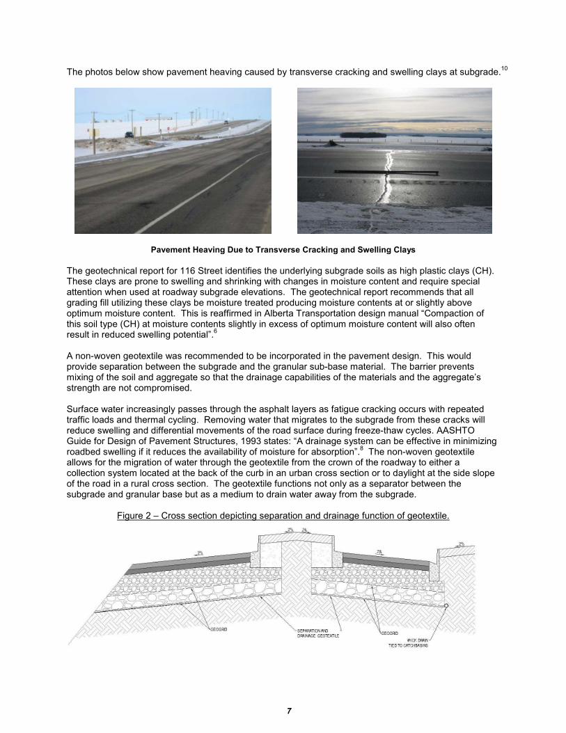
The photos below show pavement heaving caused by transverse cracking and swelling clays at subgrade.10
Pavement Heaving Due to Transverse Cracking and Swelling Clays
The geotechnical report for 116 Street identifies the underlying subgrade soils as high plastic clays (CH). These clays are prone to swelling and shrinking with changes in moisture content and require special attention when used at roadway subgrade elevations. The geotechnical report recommends that all grading fill utilizing these clays be moisture treated producing moisture contents at or slightly above optimum moisture content. This is reaffirmed in Alberta Transportation design manual “Compaction of this soil type (CH) at moisture contents slightly in excess of optimum moisture content will also often result in reduced swelling potential”.
6
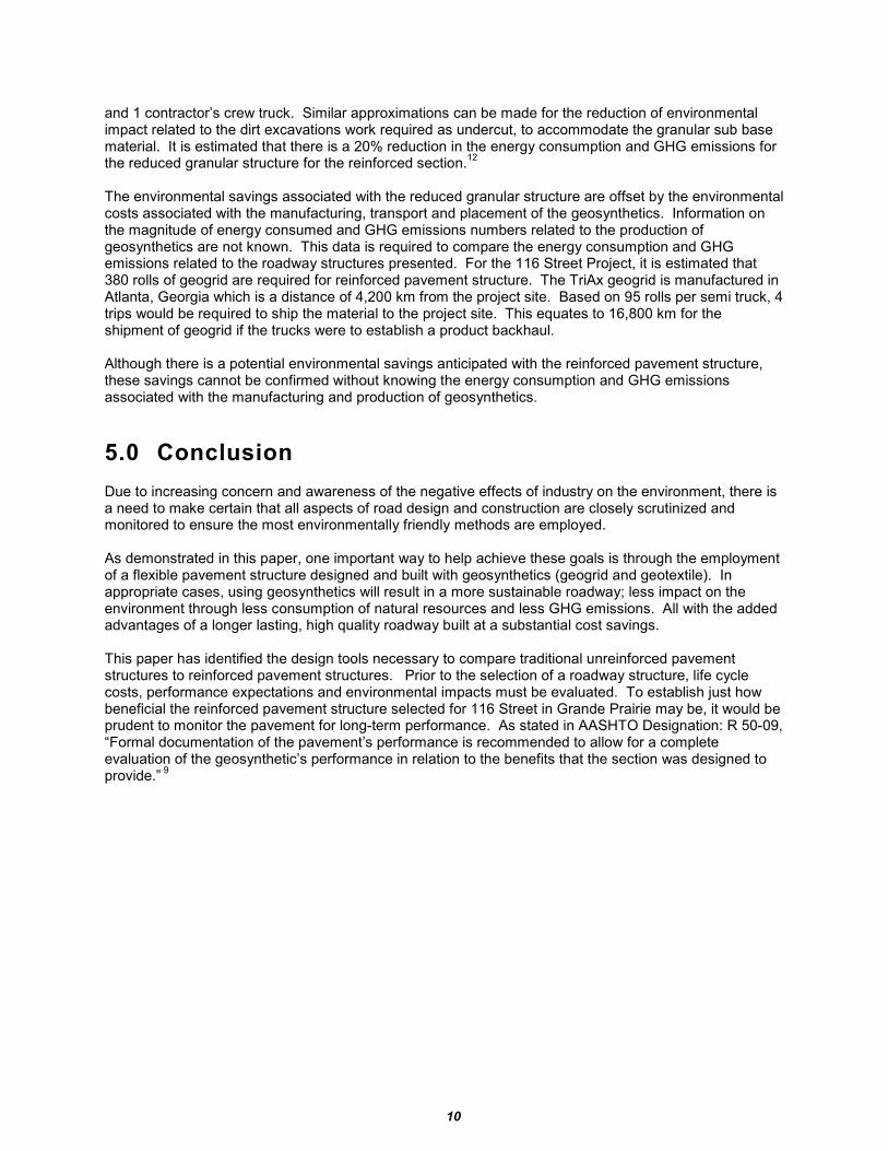
A non-woven geotextile was recommended to be incorporated in the pavement design. This would provide separation between the subgrade and the granular sub-base material. The barrier prevents mixing of the soil and aggregate so that the drainage capabilities of the materials and the aggregate’s strength are not compromised. Surface water increasingly passes through the asphalt layers as fatigue cracking occurs with repeated traffic loads and thermal cycling. Removing water that migrates to the subgrade from these cracks will reduce swelling and differential movements of the road surface during freeze-thaw cycles. AASHTO Guide for Design of Pavement Structures, 1993 states: “A drainage system can be effective in minimizing roadbed swelling if it reduces the availability of moisture for absorption”.
8 The non-woven geotextile
allows for the migration of water through the geotextile from the crown of the roadway to either a collection system located at the back of the curb in an urban cross section or to daylight at the side slope of the road in a rural cross section. The geotextile functions not only as a separator between the subgrade and granular base but as a medium to drain water away from the subgrade.
Figure 2 – Cross section depicting separation and drainage function of geotextile.

8
3.0 Life Cycle Cost Analysis
A life cycle cost analysis was performed for the project. Initial construction costs for both the unreinforced and the reinforced options were established by using unit rates from previously completed City projects that were of similar size and scope. The initial construction costs for the pavement structures were computed for both phases of the project. These costs are shown as pre-tender probable costs and are compared in Table 3. The pre-tender probable cost for the unreinforced design was computed at $1,879,275. The pre-tender cost for the reinforced design with 2 layers of geogrid and a layer of geotextile was computed at $1,685,840. The reinforced option indicated an initial construction cost savings of $193,435 as shown in Table 4 on the following page.
Table 3 – Construction Costs for Alternate Pavement Structure
Phase 1 (84 Avenue to 97 Avenue)
Option 1 – Unreinforced Pavement Structure; No Geotextile
Bid Item Quantity Units Pre-tender Probable Costs Tendered Costs 300mm GBC
A 29,500 m
2 12.00 354,000 13.78 406,510
490mm GSBCB
29,500 m2 19.65 579,675 23.04 679,680
Waste ExcavationD 14,500 m
3 8.00 116,000 17.35 251,575
Construction Costs $39.65 / m2 $1,049,675 $54.17 / m
2 $1,337,765
Option 2 – 2 layers of Geogrid Reinforcement Pavement Structure; 1 Layer Geotextile
Bid Item Quantity Units Pre-tender Probable Costs Tendered Costs 300mm GBC
A 29,500 m
2 12.00 354,000 13.78 406,510
Geogrid 29,500 m2 5.25 154,875 4.31 127,145
165mm GSBCB 29,500 m
2 6.62 195,290 7.76 228,920
Geogrid 29,500 m2 5.25 154,875 4.31 127,145
Non-woven Geotextile 29,500 m2 1.50 44,250 1.43 42,185
Waste ExcavationD
5,000 m3 8.00 40,000 17.35 86,750
Construction Costs $38.62 / m2 $943,290 $48.94 / m
2 $1,018,655
Phase 2 (68 Avenue to 84 Avenue)
Option 1 – Unreinforced Pavement Structure; No Geotextile
Bid Item Quantity Units Pre-tender Probable Costs Tendered Costs 300mm GBC
A 25,500 m
2 12.00 306,000 15.13 385,815
395mm GSBCB
27,500 m2 15.84 435,600 18.59 511,225
Waste ExcavationD 11,000 m
3 8.00 88,000 17.35 190,850
Construction Costs $35.84 / m2 $829,600 $51.07 / m
2 $1,087,890
Option 2 – 2 layers of Geogrid Reinforcement Pavement Structure; 1 Layer Geotextile
Bid Item Quantity Units Pre-tender Probable Costs Tendered Costs 225mm GBC
A 25,500 m
2 9.00 229,500 11.35 289,425
Geogrid 27,500 m2 5.25 144,375 4.31 118,525
150mm GSBCB 27,500 m
2 6.02 165,550 7.06 194,150
Geogrid 27,500 m2 5.25 144,375 4.31 118,525
Non-woven Geotextile 28,500 m2 1.50 42,750 1.43 40,755
Waste ExcavationD
2,000 m3 8.00 16,000 17.35 34,700
Construction Costs $35.02 / m2 $742,550 $45.81 / m
2 $796,080
A Alberta Transportation Designation 2 Class 20 B Alberta Transportation Designation 2 Class 40 C Bid item not tendered; cost determined at 7.76*(490/165) D Waste excavation based on depth of sub-base granular base course

9
Table 4 - Construction Cost Savings for Reinforced Pavement Structure
Pre-tender Probable Costs Tendered Costs Phase 1 $1.03 / m
2 $106,385 $5.23 / m
2 $319,110
Phase 2 $0.82 / m2 $87,050 $5.26 / m
2 $291,810
Combined – Phase 1 and Phase 2 $193,435 $610,920 The life cycles costs for both options are based on the same design life cycle period of 25 years. The subgrade properties, material properties, traffic values, environmental factors and other variables are assumed to be equivalent for each design option. In other words, future costs associated with maintenance (i.e., chip seal, crack filling, pothole repair) and rehabilitation (asphalt overlay) will occur at the same time intervals as the roadway ages for each design option. Similar to the life cycle costs, the salvage value is assumed to be the same for both design options at year 25. An initial cost savings of more than $600,000 is a substantial benefit for the 116 Street Upgrading Project. There are, however, many other benefits that are difficult to quantify in terms of dollar amounts for the reinforced pavement structure. These hidden benefits include improved ability to meet compaction requirements over soft subgrades, increased site mobility and improved ease of construction. Environmental benefits include the conservation of aggregate and reduced energy consumption and green house gas (GHG) emissions based on a reduced duration of construction. As previously identified, geotextile installed at the subgrade level provides the hidden benefits of separation and drainage. “Relative agreement exists that substantial benefits can be achieved from the inclusion of geogrids within pavement systems; however, the quantity of the improvement is in relative disagreement.”
11
4.0 Environmental Considerations
The reinforced pavement design reduces the volume of granular base course required for the roadway significantly. The estimated total reduction of granular base course is shown in Table 5 at approximately 18,000 m
3.
Table 5 – Estimated Granular Base Course Reduction
Phase 1 (84 Avenue to 97 Avenue) Pavement Structure Area (m
2) Depth (m) Volume(m
3)
Granular Sub Base Course Not reinforced 29,500 0.490 14,455 Granular Sub Base Course Reinforced 29,500 0.165 4,868 Reduced granular base course 9,587 Phase 2 (68 Avenue to 84 Avenue) Granular Base Course Not reinforced 25,500 0.300 7,650 Granular Base Course Reinforced 25,500 0.225 5,738 Reduced granular base course 1,912 Granular Sub Base Course Not reinforced 27,500 0.395 10,863 Granular Sub Base Course Reinforced 27,500 0.150 4,125 Reduced granular base course 6,738 Estimated Total Reduction of Granular Base Course 18,237 Each cubic meter of crushed aggregate must be hauled in diesel trucks and then placed and compacted on site using graders, packers and water trucks. This equipment burns diesel fuel releasing tons of emissions into the atmosphere. The total number of trips required to haul 18,000 m
3 of crushed
aggregate to site is estimated at 1,200 trips using tri-axial truck and tri-axial trailer. This equates to 60,000 km for a 25 km distance established from aggregate source to project site. To place and compact the 18,000 m
3 of crushed gravel material, six construction days are estimated. Equipment used during
those days would include: 1 loader, 2 steel packers, 1 rubber tire roller, 1 water truck, 1 foreman’s truck
10
and 1 contractor’s crew truck. Similar approximations can be made for the reduction of environmental impact related to the dirt excavations work required as undercut, to accommodate the granular sub base material. It is estimated that there is a 20% reduction in the energy consumption and GHG emissions for the reduced granular structure for the reinforced section.
12
The environmental savings associated with the reduced granular structure are offset by the environmental costs associated with the manufacturing, transport and placement of the geosynthetics. Information on the magnitude of energy consumed and GHG emissions numbers related to the production of geosynthetics are not known. This data is required to compare the energy consumption and GHG emissions related to the roadway structures presented. For the 116 Street Project, it is estimated that 380 rolls of geogrid are required for reinforced pavement structure. The TriAx geogrid is manufactured in Atlanta, Georgia which is a distance of 4,200 km from the project site. Based on 95 rolls per semi truck, 4 trips would be required to ship the material to the project site. This equates to 16,800 km for the shipment of geogrid if the trucks were to establish a product backhaul. Although there is a potential environmental savings anticipated with the reinforced pavement structure, these savings cannot be confirmed without knowing the energy consumption and GHG emissions associated with the manufacturing and production of geosynthetics.
5.0 Conclusion
Due to increasing concern and awareness of the negative effects of industry on the environment, there is a need to make certain that all aspects of road design and construction are closely scrutinized and monitored to ensure the most environmentally friendly methods are employed. As demonstrated in this paper, one important way to help achieve these goals is through the employment of a flexible pavement structure designed and built with geosynthetics (geogrid and geotextile). In appropriate cases, using geosynthetics will result in a more sustainable roadway; less impact on the environment through less consumption of natural resources and less GHG emissions. All with the added advantages of a longer lasting, high quality roadway built at a substantial cost savings. This paper has identified the design tools necessary to compare traditional unreinforced pavement structures to reinforced pavement structures. Prior to the selection of a roadway structure, life cycle costs, performance expectations and environmental impacts must be evaluated. To establish just how beneficial the reinforced pavement structure selected for 116 Street in Grande Prairie may be, it would be prudent to monitor the pavement for long-term performance. As stated in AASHTO Designation: R 50-09, “Formal documentation of the pavement’s performance is recommended to allow for a complete evaluation of the geosynthetic’s performance in relation to the benefits that the section was designed to provide.”
9

11
6.0 References
1Robert M. Koerner, Designing with Geosynthetics; 4
th Edition. 1999.
2Tensar International Corporation, Performance-Based Specifications for Roadways, 2010 3City of Grande Prairie, Request for Proposal 08-500-10, 2010, 116 Avenue Upgrading; 68 Avenue to 97 Avenue. 2010. 4JR Paine & Associates Ltd., Pavement Design 116 Street; 97 Avenue to 68 Avenue, Grande Prairie, Alberta. June 2010. 5Asphalt Institute, Asphalt Pavements for Highways & Streets Manual Series No. 1 (MS-1); Thickness Design. 1981. 6Alberta Transportation and Utilities Pavement Design Manual; Edition 1. June 1997. 7Tensar International Corporation, Pavement Design Report; 116 Street – Grande Prairie; TIC Project #W10821. September 2010. 8AASHTO Guide for Design of Pavement Structures; American Association of State Highway and Transportation Officials. 1993. 9AASHTO, 2009. Standard Practice for Geosynthetic Reinforcement of the Aggregate Base Course of Flexible Pavement Structures. AASHTO Designation R50-09. American Association of State Highway and Transportation Officials. 10EBA, A Tetra Tech Company, The Effects of Low Temperature Transverse Cracking and a Swelling Clay Subgrade on Pavement Heaving on Highway 43, 14
th Annual Transportation Conference, March
14-15, 2011. 11Department of the Army, U.S. Army Corps of Engineers, 2003. Use of Geogrids in Pavement Construction, Engineering Technical Letter 1110-1-189. 12COLASCANADA (Sintra Inc.), The environmental road of the future: Analysis of energy consumption and greenhouse gas emissions, a paper prepared for 2008 Annual Conference of the Transportation Association of Canada, Toronto, Ontario.