gas springs technical information - betz s.r.o ... · 4 1. gas springs, properties and operation...
TRANSCRIPT

Gas Spr ing s
Techn i c a l I nformat ion
. . . t e c h n o l o g y g i v e s c o m f o r t

2
Preface
In the early sixties, STABILUS became the first company in the worldto develop the Gas spring for mass production. Since then, over 1.5billion Stabilus gas springs have been produced. The first high volumeapplications were automobile doors and swivel chairs, whose comfortand reliability were enhanced by the properties of the gas springs.In the meantime, the gas spring has found its way into numerous tech-nical applications in all branches of industry as an indispensabledesign element.
This brochure is mainly intended as an informative reference documentfor engineers and salesmen, as well as for technical college anduniversity graduates, without actually claiming to be an instructionmanual. The basic physical properties of the gas spring are high-lighted, as they are of considerable interest to the design engineer.The subsequent description of the gas spring variants is subdividedaccording to their function and application. Hence the LIFT-O-MAT®
gas springs are discussed first, followed by a description ofthe infinitely-variable BLOC-O-LIFT® locking gas springs; theSTAB-O-MAT® / STAB-O-BLOC®.
The final portion of the information booklet describes theHYDRO-BLOC® locking elements, as well as a procedure for selectingthe proper gas spring.Due to the inherent flexibility of gas springs, the representation of alltypes and application options is beyond the scope of this brochure.Therefore, we will be focusing primarily on the most common gasspring variations.
STABILUS has set the standard for gas spring technology through ourlong-standing experience in development, production and industryconsultation. The contents of this brochure is a reflection of ourcompetence as the world market leader. We hope this brochure willprove useful to both old and new friends of our company.
Koblenz, January 2007 STABILUS GmbH
© STABILUS GmbHAll rights reserved. No part of this publication may be reprinted orbe reproduced without our prior permission.

1. Gas Springs, Properties and Operation 41.1 Physical Properties of the Ideal Gas Spring 4
1.1.1 Spring Force and Characteristic Curve of the IdealGas Spring 4
1.1.2 Force Ratio of the Ideal Gas Spring 51.1.3 Work of the Ideal Gas Spring 6
1.2 Technical Gas Spring Real 61.2.1 Spring Force and Spring Characteristic of the
Technical Gas Spring 61.2.2 Temperature Behavior of the Technical Gas Spring 71.2.3 Lifetime of the Technical Gas Spring 8
2. Gas Springs for Force Supply 92.1 STABILUS Gas Spring LIFT-O-MAT® 9
2.1.1 LIFT-O-MAT® Piston Package 92.1.2 LIFT-O-MAT® Seal and Guide Element 102.1.3 LIFT-O-MAT® End Fittings 112.1.4 LIFT-O-MAT® Gas Spring with Hydraulic and
Dynamic Motion 122.1.5 LIFT-O-MAT® with a Decreasing or Progressive
Spring Characteristic Curve 122.1.6 LIFT-O-MAT® with End Position Locking 132.1.7 LIFT-O-MAT® FR 14
2.2 STABILUS Gas Spring HYDRO-LIFT® 152.3 STABILUS Gas Spring HYDRO-LIFT-T 152.4 STABILUS Gas Spring KOMBI-LIFT 162.5 STABILUS Gas Spring INTER-STOP 162.6 STABILUS Gas Spring ELEKTRO-LIFT 172.7 Lightweight Design: Gas Springs with Aluminum
Pressure Tube 172.8 Gas Springs with Shrink Tube 172.9 Tips on Installation and Use 18
3. Gas Springs for Force Supply and Variable Position Lock 193.1 STABILUS Gas Spring BLOC-O-LIFT® 193.2 Valve Actuation Range and Damping 193.3 BLOC-O-LIFT® Standard Actuation 203.4 Locking Characteristics of BLOC-O-LIFT® Gas Springs 20
3.4.1 BLOC-O-LIFT®, Spring-Locking 203.4.2 BLOC-O-LIFT®, Rigid-Locking 203.4.3 BLOC-O-LIFT®, Position-Independent,
Rigid-Locking 203.4.4 BLOC-O-LIFT®, Position-Dependent,
Rigid-Locking 21
3. 5 Tips on Installation and Use 223.6 Stabilus Gas Springs STAB-O-MAT® and STAB-O-BLOC® 22
3.6.1 STAB-O-MAT® and STAB-O-BLOC® Valve Systems 233.6.2 STAB-O-MAT® and STAB-O-BLOC® Columns 233.6.3 STABILUS Outer Tube with Bottom Spring 243.6.4 STABILUS Telescope Outer Tube 243.6.5 Multi-Function Column 243.6.6 Non-Twisting Column 253.6.7 Column with Additional Stop Function 253.6.8 Tips on Installation and Use 25
3.7 STABILUS Actuation Systems for Locking Gas Springs 25
4. STABILUS Locking Elements without Extension Force:HYDRO-BLOC® 26
5. Gas Spring Range and Mounting Situation 275.1 Estimation of Extension Force F1 275.2 Calculation of the Manual Force Characteristic,
Simulation Calculation 27
6. Appendix 306.1 Used Symbols and Units 306.2 Worksheet 10014184 31
3
Contents

4
1. Gas Springs, Properties and Operation
Gas springs are primarily used to provide a counterbalance or force assistance, but can also be used to provide damping or an end-stop.In any case, gas springs are implemented to achieve a comfortable andreliable adjustment function, in addition to a leaving a clear mark ofquality on the end product.
The gas spring’s function is based on the potential energy of com-pressed gas, and compared to mechanical springs, offer the followingadvantages:
- a flat spring rate which means a relative constant force,even for high forces and over long strokes,
- compact construction- straightforward and quick assembly- a selectable linear, digressive or progressive characteristic,
given a similar outer shape.- damped motion control, definable over specific positions
or over the full stroke.- infinitely lockable - rigid or elastic in locked position - end stop function
Further gas spring functions can be realized using combinations of theabove properties. Devices with dampened adjustment motion arefrequently used in combination with end-position locking. A furthervariant is the design of devices with dampened motion and progressivespring characteristic etc. According to the function and application,STABILUS gas springs are subdivided into three types:
The LIFT-O-MAT® gas spring is primarily intended as an force elementfor position adjustment. Typical application examples in the auto-motive industry are gas springs which allow easy opening of Tailgates,Trunklids and Hoods.
The BLOC-O-LIFT® locking gas spring fulfils the same tasks as theLIFT-O-MAT®; however, the BLOC-O-LIFT® additionally allows infinitely-variable locking. Applications for the BLOC-O-LIFT® are the backadjustment in swivel chairs and the recline adjustment in hospitalbedsSTAB-O-MAT® and STAB-O-BLOC® locking gas springs are used toadjust the height of swivel chairs.The supporting columns with these gassprings can withstand transverse forces and bending moments whileproviding infinitely-variable height adjustment and comfortablecushioning.
1.1 Physical Properties of the Ideal Gas Spring
In order to explain the basic function and physical properties of the gasspring on an understandable mathematical basis, an ideal model willbe applied. Therefore, the influences of friction, flow and temperaturewill not be considered in this section. This ideal model can be appliedto all varieties of the gas spring, regardless of the construction.
The gas spring is a closed system consisting of a pressure tube and piston rod with piston, as well as compressed Nitrogen (N2) as an energysource and a lubrication oil. Figure 1.1. shows a block diagram of thegas spring
1.1.1 Spring Force and Characteristic Curve of the Ideal GasSpring
The piston rod with cross section AK is axially guided within the pressure tube as shown in figure 1.1. The cross section of the pressuretube is designated with AR (see figure 1.1.) A seal between the pistonrod and pressure tube seals off pressurized gas p from the ambientpressure pU. A nozzle in the piston ensures that the pressure is the same on both sides of the piston.Balancing the forces on the piston in any position yields:
F+p·(AR-AK)-p·AR = 0F = p·AK (1)
Figure 1.1: Diagram of the gas spring
5
1. Gas Springs, Properties and Operation
The spring force F is thus the product of the inside pressure and the piston rod cross sectional area. In the extended position, the pressureof the gas spring (s=s 1 ) is p1. The resultant spring force in the extended position is:
F1 = p1·AK
As the piston rod is pushed into the pressure tube, the gas volume isreduced by the volume of the inserted piston rod, resulting in an increase in pressure. Therefore, the gas spring in the compressed condition (s=s2 ) at pressure = p2 will yield a spring force of:
F2 = p2·AK
Both forces have been plotted on the diagram in figure 1.1 which illustrates a linear relationship. In the ideal gas spring, this characteristic curve applies to the compression and extension force of the gas spring.
The correlation between the change in pressure and volume isdescribed by the following polytropic equation:
p·Vn = Constant = p1·V
1n
The shape of the characteristic curve can be calculated using equation
F = p1·AK(V1 / V)n (2)
with V = V1-AK
and V1 = AR·(s2-s1)
where V1 is the compressible gas volume in extended condition, i.e.at the start of the stroke s1 of the gas spring. AK·s is the volume of the inserted piston rod.Equation [2] indicates the parameters which influence the characteristiccurve of the gas spring. They are as follows:
- the pressure of the filled gas p1 ,- the cross-section of the piston rod AK ,the available gas volume V1
or respectively the cross-section of pressure-tube AR.
By varying the above factors in equation [2] we obtain the curve shownin figure 1.2. which illustrates the isothermal change of condition(n=1). This simplification is applicable if the gas spring is not actuated continuously, as the temperature of the gas during the compression of the piston rod is nearly constant.
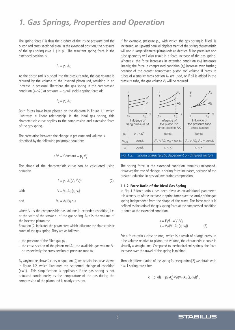
If for example, pressure p1, with which the gas spring is filled, is increased, an upward parallel displacement of the spring characteristicwill occur. Larger diameter piston rods at identical filling pressures andtube geometry will also result in a force increase of the gas spring.Whereas the force increases in extended condition (s1) increases linearly, the force in compressed condition (s2) increase even further,because of the greater compressed piston rod volume. If pressure tubes of a smaller cross-section AR are used, or if oil is added in thepressure tube, the gas volume V1 will be reduced.
The spring force in the extended condition remains unchanged.However, the rate of change in spring force increases, because of thegreater reduction in gas volume during compression.
1.1.2. Force Ratio of the Ideal Gas SpringIn Fig. 1.2 force ratio x has been given as an additional parameter.It is a measure of the increase in spring force over the stroke of the gasspring independent from the shape of the curve. The force ratio x is defined as the ratio of the gas spring force at the compressed conditionto force at the extended condition.
x = F2/F1 = V1/V2
x = V1/(V1-AK·(s2-s1)) (3)
For a force ratio x close to one, which is a result of a large pressuretube volume relative to piston rod volume, the characteristic curve isvirtually a straight line. Compared to mechanical coil springs, the forceincrease over the travel of the spring is minimal.
Through differentiation of the spring force equation [2] we obtain withn = 1 spring rate c for:
c = dF/ds = p1·A ·V1/(V1-AK )2 .K2
Fig. 1.2: Spring characteristic dependent on different factors
·(s2-s1)
·(s2-s1)
6
1. Gas Springs, Properties and Operation
Given a linear spring characteristic curve, the spring rigidity can be calculated in a straightforward manner using the difference quotientsof the spring characteristic:
c = ΔF/Δs = F1·(x-1)/(s2 -s1) (4)
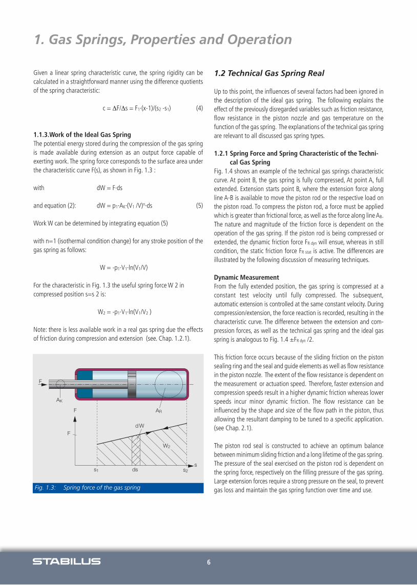
1.1.3.Work of the Ideal Gas SpringThe potential energy stored during the compression of the gas springis made available during extension as an output force capable of exerting work. The spring force corresponds to the surface area underthe characteristic curve F(s), as shown in Fig. 1.3 :
with dW = F·ds
and equation (2): dW = p1·AK·(V1 /V)n·ds (5)
Work W can be determined by integrating equation (5)
with n=1 (isothermal condition change) for any stroke position of thegas spring as follows:
W = -p1·V1·ln(V1/V)
For the characteristic in Fig. 1.3 the useful spring force W 2 incompressed position s=s 2 is:
W2 = -p1·V1·ln(V1/V2 )
Note: there is less available work in a real gas spring due the effectsof friction during compression and extension (see. Chap. 1.2.1).
1.2 Technical Gas Spring Real
Up to this point, the influences of several factors had been ignored inthe description of the ideal gas spring. The following explains the effect of the previously disregarded variables such as friction resistance,flow resistance in the piston nozzle and gas temperature on the function of the gas spring. The explanations of the technical gas springare relevant to all discussed gas spring types.
1.2.1 Spring Force and Spring Characteristic of the Techni-cal Gas Spring
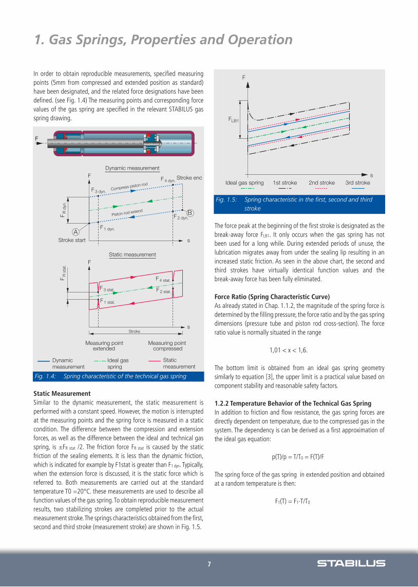
Fig. 1.4 shows an example of the technical gas springs characteristiccurve. At point B, the gas spring is fully compressed, At point A, full extended. Extension starts point B, where the extension force along line A-B is available to move the piston rod or the respective load onthe piston road. To compress the piston rod, a force must be appliedwhich is greater than frictional force, as well as the force along line AB.The nature and magnitude of the friction force is dependent on theoperation of the gas spring. If the piston rod is being compressed orextended, the dynamic friction force FR dyn will ensue, whereas in stillcondition, the static friction force FR stat is active. The differences are illustrated by the following discussion of measuring techniques.
Dynamic MeasurementFrom the fully extended position, the gas spring is compressed at a constant test velocity until fully compressed. The subsequent,automatic extension is controlled at the same constant velocity. Duringcompression/extension, the force reaction is recorded, resulting in thecharacteristic curve. The difference between the extension and com-pression forces, as well as the technical gas spring and the ideal gasspring is analogous to Fig. 1.4 ±FR dyn /2.
This friction force occurs because of the sliding friction on the pistonsealing ring and the seal and guide elements as well as flow resistancein the piston nozzle. The extent of the flow resistance is dependent onthe measurement or actuation speed. Therefore, faster extension andcompression speeds result in a higher dynamic friction whereas lowerspeeds incur minor dynamic friction. The flow resistance can be influenced by the shape and size of the flow path in the piston, thusallowing the resultant damping to be tuned to a specific application.(see Chap. 2.1).
The piston rod seal is constructed to achieve an optimum balance between minimum sliding friction and a long lifetime of the gas spring.The pressure of the seal exercised on the piston rod is dependent onthe spring force, respectively on the filling pressure of the gas spring.Large extension forces require a strong pressure on the seal, to preventgas loss and maintain the gas spring function over time and use.Fig. 1.3: Spring force of the gas spring
7
1. Gas Springs, Properties and Operation
In order to obtain reproducible measurements, specified measuringpoints (5mm from compressed and extended position as standard) have been designated, and the related force designations have beendefined. (see Fig. 1.4) The measuring points and corresponding forcevalues of the gas spring are specified in the relevant STABILUS gasspring drawing.
Static MeasurementSimilar to the dynamic measurement, the static measurement is performed with a constant speed. However, the motion is interruptedat the measuring points and the spring force is measured in a staticcondition. The difference between the compression and extension forces, as well as the difference between the ideal and technical gasspring, is ±FR stat /2. The friction force FR stat is caused by the static friction of the sealing elements. It is less than the dynamic friction,which is indicated for example by F1stat is greater than F1 dyn. Typically,when the extension force is discussed, it is the static force which is referred to. Both measurements are carried out at the standard temperature T0 =20°C. these measurements are used to describe allfunction values of the gas spring.To obtain reproducible measurementresults, two stabilizing strokes are completed prior to the actual measurement stroke.The springs characteristics obtained from the first,second and third stroke (measurement stroke) are shown in Fig. 1.5.
The force peak at the beginning of the first stroke is designated as thebreak-away force FLB1. It only occurs when the gas spring has not been used for a long while. During extended periods of unuse, the lubrication migrates away from under the sealing lip resulting in an increased static friction. As seen in the above chart, the second andthird strokes have virtually identical function values and the break-away force has been fully eliminated.
Force Ratio (Spring Characteristic Curve)As already stated in Chap. 1.1.2, the magnitude of the spring force isdetermined by the filling pressure, the force ratio and by the gas springdimensions (pressure tube and piston rod cross-section). The force ratio value is normally situated in the range
1,01 < x < 1,6.
The bottom limit is obtained from an ideal gas spring geometry similarly to equation [3], the upper limit is a practical value based oncomponent stability and reasonable safety factors.
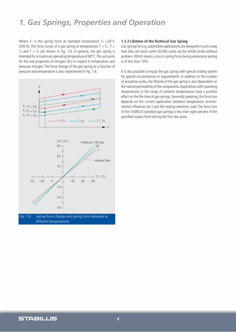
1.2.2 Temperature Behavior of the Technical Gas SpringIn addition to friction and flow resistance, the gas spring forces are directly dependent on temperature, due to the compressed gas in thesystem. The dependency is can be derived as a first approximation ofthe ideal gas equation:
p(T)/p = T/T0 = F(T)/F
The spring force of the gas spring in extended position and obtainedat a random temperature is then:
F1(T) = F1·T/T0
Fig. 1.4: Spring characteristic of the technical gas spring
Fig. 1.5: Spring characteristic in the first, second and thirdstroke
8
Where F1 is the spring force at standard temperature T0 =20°C (293 K). The force curves of a gas spring at temperatures T = T0 , T >T0 and T < T0 are shown in Fig. 1.6. In general, the gas spring is intended for a maximum operating temperature of 80°C.This accountsfor the real properties of nitrogen (N2) in respect to temperature andpressure changes. The force change of the gas spring as a function ofpressure and temperature is also represented in Fig. 1.6.
1.2.3 Lifetime of the Technical Gas SpringGas springs for e.g. automobile applications are designed in such a waythat they can reach some 50,000 cycles via the whole stroke withoutproblem.Which means a loss in spring force during endurance testingis of less than 10%.
It is also possible to equip the gas spring with special sealing systemfor special circumstances or requirements. In addition to the numberof actuation cycles, the lifetime of the gas spring is also dependent onthe natural permeability of the components.Applications with operatingtemperatures in the range of ambient temperatures have a positive effect on the life-time of gas springs. Generally speaking, the force lossdepends on the current application (ambient temperature, environ-mental influences etc.) and the sealing elements used. The force lossof the STABILUS standard gas springs is less than eight percent of thespecified output force during the first two years.
s
F
F1 (T = T0)F1 (T > T0)
F1 (T < T0)
T > T0 T < T0T0T=
10
20
30
-30
-20
-10
0-20-40 806040T [ C ]
Fülldruck 100 bar50
1
ideales Gas
Fig. 1.6: Spring force change and spring force behavior atdifferent temperatures
1. Gas Springs, Properties and Operation
9
2. Gas Springs for Force Supply
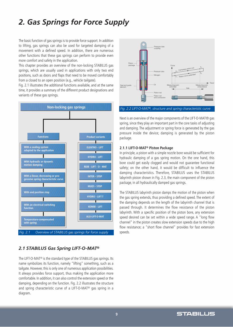
The basic function of gas springs is to provide force support. In additionto lifting, gas springs can also be used for targeted damping of a movement with a defined speed. In addition, there are numerousother functions that these gas springs can perform to provide even more comfort and safety in the application.This chapter provides an overview of the non-locking STABILUS gassprings, which are usually used in applications with only two end positions, such as doors and flaps that need to be moved comfortablyfrom a closed to an open position (e.g., vehicle tailgate).Fig. 2.1 illustrates the additional functions available, and at the sametime, it provides a summary of the different product designations andvariants of these gas springs.
2.1 STABILUS Gas Spring LIFT-O-MAT®
The LIFT-O-MAT® is the standard type of the STABILUS gas springs. Itsname symbolizes its function, namely "lifting" something, such as atailgate. However, this is only one of numerous application possibilities.It always provides force support, thus making the application morecomfortable. In addition, it can also control the extension speed or thedamping, depending on the function. Fig. 2.2 illustrates the structureand spring characteristic curve of a LIFT-O-MAT® gas spring in a diagram.
Next is an overview of the major components of the LIFT-O-MAT® gasspring, since they play an important part in the core tasks of adjustingand damping. The adjustment or spring force is generated by the gaspressure inside the device; damping is generated by the piston package.
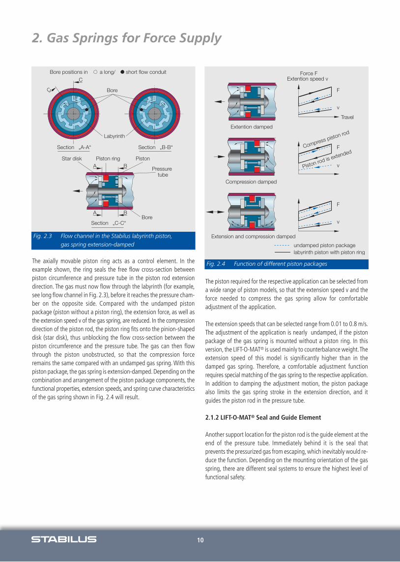
2.1.1 LIFT-O-MAT® Piston PackageIn principle, a piston with a simple nozzle bore would be sufficient forhydraulic damping of a gas spring motion. On the one hand, this bore could get easily clogged and would not guarantee functional safety; on the other hand, it would be difficult to influence the damping characteristics. Therefore, STABILUS uses the STABILUS labyrinth piston shown in Fig. 2.3, the main component of the pistonpackage, in all hydraulically damped gas springs.
The STABILUS labyrinth piston damps the motion of the piston whenthe gas spring extends, thus providing a defined speed. The extent ofthe damping depends on the length of the labyrinth channel that ispassed through. It determines the flow resistance of the piston labyrinth. With a specific position of the piston bore, any extensionspeed desired can be set within a wide speed range. A "long flow channel" in the piston creates slow extension speeds due to the highflow resistance; a "short flow channel" provides for fast extensionspeeds.Fig. 2.1 Overview of STABILUS gas springs for force supply
Fig. 2.2 LIFT-O-MAT®, structure and spring characteristic curve
10
2. Gas Springs for Force Supply
The axially movable piston ring acts as a control element. In the example shown, the ring seals the free flow cross-section between piston circumference and pressure tube in the piston rod extension direction. The gas must now flow through the labyrinth (for example,see long flow channel in Fig. 2.3), before it reaches the pressure cham-ber on the opposite side. Compared with the undamped piston package (piston without a piston ring), the extension force, as well asthe extension speed v of the gas spring, are reduced. In the compressiondirection of the piston rod, the piston ring fits onto the pinion-shapeddisk (star disk), thus unblocking the flow cross-section between the piston circumference and the pressure tube. The gas can then flowthrough the piston unobstructed, so that the compression force remains the same compared with an undamped gas spring. With thispiston package, the gas spring is extension-damped. Depending on thecombination and arrangement of the piston package components, thefunctional properties, extension speeds, and spring curve characteristicsof the gas spring shown in Fig. 2.4 will result.
The piston required for the respective application can be selected froma wide range of piston models, so that the extension speed v and theforce needed to compress the gas spring allow for comfortable adjustment of the application.
The extension speeds that can be selected range from 0.01 to 0.8 m/s.The adjustment of the application is nearly undamped, if the pistonpackage of the gas spring is mounted without a piston ring. In this version, the LIFT-O-MAT® is used mainly to counterbalance weight.Theextension speed of this model is significantly higher than in the damped gas spring. Therefore, a comfortable adjustment function requires special matching of the gas spring to the respective application.In addition to damping the adjustment motion, the piston package also limits the gas spring stroke in the extension direction, and it guides the piston rod in the pressure tube.
2.1.2 LIFT-O-MAT® Seal and Guide Element
Another support location for the piston rod is the guide element at theend of the pressure tube. Immediately behind it is the seal that prevents the pressurized gas from escaping, which inevitably would re-duce the function. Depending on the mounting orientation of the gasspring, there are different seal systems to ensure the highest level offunctional safety.
Fig. 2.3 Flow channel in the Stabilus labyrinth piston, gas spring extension-damped
Fig. 2.4 Function of different piston packages

11
2. Gas Springs for Force Supply
Fig. 2.5 shows three gas spring variants, which only differ in the structure of their seal and guide elements. Variant I with the standardseal should preferably be in-stalled with the piston rod pointing downto ensure continuous lubrication of the seal with the lubricant accu-mulating in the seal. Variant II, however, has the STABILUS double seal system, which allows for mounting in any orientation. Even if thegas spring is mounted with the piston rod pointing upward, the oil enclosed between the seals ensures the lubrication of both seals. Thesecond seal extends the life of the gas spring; therefore, this model isused in applications that require a high number of duty cycles.
Variant III has the STABILUS oil chamber. This variant is suitable forapplications where the gas spring swivels when the application is adjusted, thus changing its position. If the gas spring is mounted withthe piston rod pointing down, it fills up the oil reservoir, in which theoil flows along the free ring slot on the oil chamber jacket. If the gasspring then swivels, for example when the application is opened, andthe piston rod points upward, there will still be enough oil in the reservoir to lubricate the seal.
All seal systems can be augmented by a "felt chamber" upon request.In that case, a felt ring impregnated with special grease provides additional lubrication of the piston rod across the entire stroke. This reduces the friction and breakaway force further, thus ensuring the optimum function of the gas spring even in sensitive applications.
Dust and contaminant deposits on the piston rod can have a negativeimpact on the life of gas springs. In environmental conditions that areless than optimal, a protective tube offers protection against contaminants, dust, moisture, or possible mechanical impact on the piston rod. In that case, a mounting orientation should be selected thatprevents the protective tube from getting filled with contaminants ormoisture.
In order to improve the functional safety and corrosion resistance evenfurther, additional protective caps made of plastic protect the crimpingand beading area of the gas spring against moisture, dust, and contaminants.
2.1.3 LIFT-O-MAT® End FittingsA large variety of end fittings allows for fast and easy installation ofthe gas spring in the application. Fig. 2.6 shows a selection of Stabilus LIFT-O-MAT® gas spring end fittings, for mounting on the piston rod side or on the pressure tube side.
Fig. 2.5 LIFT-O-MAT® seal and guide element
Fig. 2.6 Selection of LIFT-O-MAT® standard fittings
12
2. Gas Springs for Force Supply
2.1.4 LIFT-O-MAT® Gas Spring with Hydraulic and DynamicMotion Damping
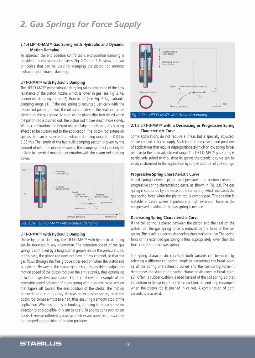
To approach the end position comfortably, end position damping isprovided in most application cases. Fig. 2.7a and 2.7b show the twoprinciples that can be used for damping the piston rod motion:hydraulic and dynamic damping.
LIFT-O-MAT® with Hydraulic Damping The LIFT-O-MAT® with hydraulic damping takes advantage of the flowresistance of the piston nozzle, which is lower in gas (see Fig. 2.7a,pneumatic damping range s2) than in oil (see Fig. 2.7a, hydraulic damping range s1). If the gas spring is mounted vertically with the piston rod pointing down, the oil accumulates at the seal and guideelement of the gas spring.As soon as the piston dips into the oil whenthe piston rod is pushed out, the piston rod moves much more slowly.With a combination of different oils and labyrinth pistons, this brakingeffect can be customized to the application. The piston rod extensionspeeds that can be selected for hydraulic damping range from 0.01 to0.35 m/s. The length of the hydraulic damping section is given by theamount of oil in the device. However, this damping effect can only beutilized in a vertical mounting orientation with the piston rod pointingdown.
LIFT-O-MAT® with Hydraulic DampingUnlike hydraulic damping, the LIFT-O-MAT® with hydraulic dampingcan be mounted in any orientation. The extension speed of the gasspring is controlled by a longitudinal groove inside the pressure tube.In this case, the piston rod does not have a flow channel, so that thegas flows through the free groove cross-section when the piston rodis adjusted. By varying the groove geometry, it is possible to adjust themotion speed of the piston rod over the entire stroke, thus optimizingit to the respective application. Fig. 2.7b shows an example of the extension speed behavior of a gas spring with a groove cross-sectionthat tapers off toward the end position of the stroke. The motion proceeds at a continuously decreasing extension speed, until the piston rod comes almost to a halt, thus ensuring a smooth stop of theapplication. When using this technology, damping in the compressiondirection is also possible; this can be useful in applications such as carhoods. Likewise, different groove geometries are possible, for examplefor damped approaching of interim positions.
2.1.5 LIFT-O-MAT® with a Decreasing or Progressive SpringCharacteristic Curve
Some applications do not require a linear, but a specially adjusted,stroke-controlled force supply. Such is often the case in end positionsof applications that require disproportionately high or low spring forcesrelative to the main adjustment range. The LIFT-O-MAT® gas spring isparticularly suited to this, since its spring characteristic curve can beeasily customized to the application by simple addition of coil springs.
Progressive Spring Characteristic CurveA coil spring between piston and pressure tube bottom creates a progressive spring characteristic curve, as shown in Fig. 2.8. The gasspring is supported by the force of the coil spring, which increases thegas spring force when the piston rod is compressed. This solution is suitable in cases where a particularly high extension force in the compressed position of the gas spring is needed.
Decreasing Spring Characteristic CurveIf the coil spring is placed between the piston and the seal on the piston rod, the gas spring force is reduced by the force of the coilspring.The result is a decreasing spring characteristic curve.The springforce of the extended gas spring is thus appropriately lower than theforce of the standard gas spring.
The spring characteristic curves of both variants can be varied by selecting a different coil spring length (it determines the break points3 of the spring characteristic curve) and the coil spring force (it determines the slope of the spring characteristic curve in break points3). Often, a rubber cushion is used instead of the coil spring, so thatin addition to the spring effect of the cushion, the end stop is dampedwhen the piston rod is pushed in or out. A combination of both variants is also used.
Fig. 2.7b LIFT-O-MAT® with dynamic damping
Fig. 2.7a LIFT-O-MAT® with hydraulic damping
13
2. Gas Springs for Force Supply
2.1.6 LIFT-O-MAT® with End Position LockingIf legal requirements demand safety precautions against unintentionaladjustment, or if the gas spring is subjected to application forces thatexceed its extension force, additional stop devices are the ideal solution.
With integrated, mechanical stop elements (see Fig. 2.9), the LIFT-O-MAT® can lock the application. A typical application exampleare mobile sales stands, in which the LIFT-O-MAT® can be used to openflaps, as well as a locking element against unintentional closing (e.g., under a heavy wind or snow load). If more than one gas springis used in an application, it is usually sufficient to equip just one of thegas springs with the mechanical stop element.
The advantages of a mechanical end position lock in LIFT-O-MAT®
gas springs can be put in a nutshell:- Locking and unlocking directly in the adjustment element - Additional protection against unintentional closing - Absorption of external forces, such as wind and snow loads
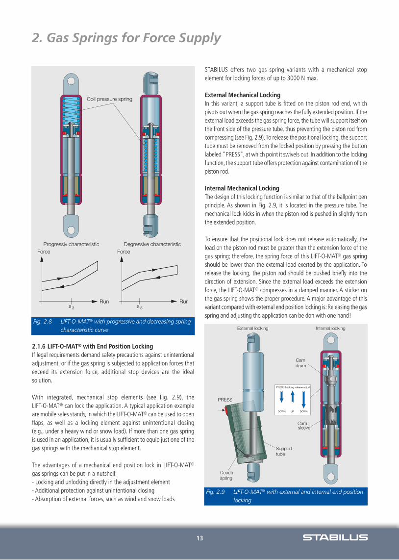
STABILUS offers two gas spring variants with a mechanical stop element for locking forces of up to 3000 N max.
External Mechanical Locking In this variant, a support tube is fitted on the piston rod end, which pivots out when the gas spring reaches the fully extended position. If theexternal load exceeds the gas spring force, the tube will support itself onthe front side of the pressure tube, thus preventing the piston rod fromcompressing (see Fig. 2.9).To release the positional locking, the supporttube must be removed from the locked position by pressing the buttonlabeled "PRESS", at which point it swivels out. In addition to the lockingfunction, the support tube offers protection against contamination of thepiston rod.
Internal Mechanical Locking The design of this locking function is similar to that of the ballpoint penprinciple. As shown in Fig. 2.9, it is located in the pressure tube. The mechanical lock kicks in when the piston rod is pushed in slightly fromthe extended position.
To ensure that the positional lock does not release automatically, the load on the piston rod must be greater than the extension force of thegas spring; therefore, the spring force of this LIFT-O-MAT® gas springshould be lower than the external load exerted by the application. To release the locking, the piston rod should be pushed briefly into the direction of extension. Since the external load exceeds the extension force, the LIFT-O-MAT® compresses in a damped manner. A sticker onthe gas spring shows the proper procedure. A major advantage of thisvariant compared with external end position locking is:Releasing the gasspring and adjusting the application can be don with one hand!
Fig. 2.8 LIFT-O-MAT® with progressive and decreasing springcharacteristic curve
Fig. 2.9 LIFT-O-MAT® with external and internal end positionlocking
14
2. Gas Springs for Force Supply
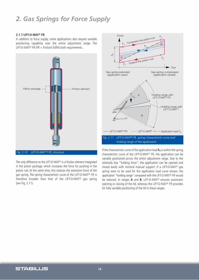
2.1.7 LIFT-O-MAT® FRIn addition to force supply, some applications also require variable positioning capability over the entire adjustment range. The LIFT-O-MAT® FR (FR = friction) fulfills both requirements.
The only difference to the LIFT-O-MAT® is a friction element integratedin the piston package, which increases the force for pushing in the piston rod. At the same time, this reduces the extension force of thegas spring. The spring characteristic curve of the LIFT-O-MAT® FR istherefore broader than that of the LIFT-O-MAT® gas spring (see Fig. 2.11).
If the characteristic curve of the application load FA is within the springcharacteristic curve of the LIFT-O-MAT® FR, the application can bevariably positioned across the entire adjustment range. Due to therelatively low "holding force", the application can be opened andclosed easily with minimal manual support. If a LIFT-O-MAT® gasspring were to be used for the application load curve shown, theapplication "holding range" compared with the LIFT-O-MAT® FR wouldbe reduced. In ranges A and B, LIFT-O-MAT® ensures automatic opening or closing of the lid, whereas the LIFT-O-MAT® FR providesfor fully variable positioning of the lid in these ranges.
Fig. 2.10 LIFT-O-MAT ® FR, structure
Fig. 2.11 LIFT-O-MAT® FR, spring characteristic curve andholding range of the application

15
2. Gas Springs for Force Supply
2.2 STABILUS Gas Spring HYDRO-LIFT®
Just like the LIFT-O-MAT® FR, the HYDRO-LIFT® provides force supplyand fully variable positioning in the application. However, the pistonof the HYDRO-LIFT® features a pressure valve on the back of the pis-ton.The valve prevents the gas exchange or the compression of thepiston rod until the spring-preloaded seal releases the piston bore.Because of the spring-loading of the seal, the force needed to push inthe piston rod is greater than the force of the regular LIFT-O-MAT® gasspring (see Fig. 2.12).
The compression force of the gas spring and/or the band width of thespring characteristics can be customized to the respective applicationby the right choice of valve coil spring.
The extension force of the HYDRO-LIFT® is selected so that the pistonrod in the application can only be extended with additional force (e.g.,manual force required to open a lid). If the external load of the appli-cation is smaller than the compression force of the HYDRO-LIFT®, thelid remains in its position within the "holding range" (see Fig. 2.11).
Depending on the design of the HYDRO-LIFT®, the holding functioncan be active across the entire adjustment range (as in the LIFT-O-MAT® FR) or in one or more partial ranges of the application. In addi-tion to the "holding range," Fig. 2.12 shows two other function ran-ges of the application. The "sink range" is achieved with one or moregrooves in the pressure tube, which serve as piston bypasses, thus neu-tralizing the function of the pressure valve. The "fall range" is createdby expanding the pressure cylinder cross section. If the piston reaches
the "sink range" when the piston rod is pushed in, it reduces the gasspring force or the manual force needed to close the lid. In the "fallrange", the lid then closes automatically.
2.3 STABILUS Gas Spring HYDRO-LIFT®-T
The opening and closing forces of a flap with gas springs are affectedby the ambient temperature, due to laws of physics. At lower temperatures, the filling medium nitrogen contracts and the spring force decreases.
At higher temperatures, the filling medium expands and the springforce increases.The HYDRO-LIFT®-T was developed to keep the temperatu-re influence as low as possible on the functional forces of a flap. This device is equipped with an additional, bimetal-controlled piston valve.At temperatures above +10°C, the valve is open. At temperatures below +10°C, the valve closes and increases the holding force.While achieving a safe holding force at temperatures as low as -30°C,this function allows for a lower extension force.
The overall lower force level relieves the coupling points of the gasspring, which makes closing with less effort much more comfortable.
Fig. 2.13 Structure of HYDRO-LIFT®-T
Application load
Droprange
Sinking
rangeHolding range
Piston boreSealValve coil spring
Run
Force
HYDRO-LIFT® LIFT-O-MAT®
Fig. 2.12 HYDRO-LIFT® with "hold, sink, and fall range”

16
2. Gas Springs for Force Supply
2.4 STABILUS Gas Spring KOMBI-LIFT
What makes the KOMBI-LIFT special are its two pre-settable positionsof the extended length, which can be a helpful feature in applicationssuch as tailgates of tall vehicles (vans), to prevent them from bumpinginto the garage roof or door. Short persons can limit the opening angleof the tailgate, making closing it easier.
To achieve this function, the KOMBI-LIFT has a switch on the pistonrod, which opens or closes the valve in the piston. (see Fig. 2.14). Thepressure tube has a groove that acts as a bypass in a certain range.Due to this combination, the KOMBI-LIFT is partly a locking and partly a non-locking gas spring – as the product name indicates.
If the valve remains open (switch position 1), the piston rod extendsfully. However, if the valve is closed (switch position 2), the piston rodextends only partially, namely in the groove area. To extend it further,all that is needed is a change in switch position, which opens the valve. Due to the special design of the piston, the piston rod can becompressed without locking, regardless of the preset switch position.
2.5 STABILUS Gas Spring INTER-STOP
The INTER-STOP makes it possible to limit the opening angles of flaps,which is useful for tailgates in garages with low ceilings, or for hoodswith a normal opening position and a service position. For this purpo-se, the function of a LIFT-O-MAT® with hydraulic damping is combinedwith the holding function of a HYDRO-LIFT. Unlike in the HYDRO-LIFT,the holding force of the INTERSTOP acts in the extension direction. De-pending on the application, two different systems can be used:
INTER-STOP without Holding Range In the first part of the stroke (range I), the INTER-STOP works like a gasspring with dynamic damping. The device stops smoothly at the holding point. With manual support in the opening direction, the valve in the piston opens, gas is exchanged between the functionareas, and the holding point is overcome. The holding force must bechosen as to ensure the stop function at a temperature of 80°C. In thesecond part of the stroke (range III), the device acts like a normal gasspring and approaches the end stop in a damped motion.
The closing of a flap with INTER-STOP is the same as with a LIFT-O-MAT.
INTER-STOP with Holding RangeIn the first part of the stroke, the device acts as described before. In theholding range, which is the latter part of the stroke, the piston valve isopened with additional manual effort, thus enabling continuos positioning of the flap until the end stop.
Fig. 2.15 Different opening functions of the INTER-STOP
1
2
2
1
turn
turn
Position switchLocking in extension
directionNon-locking
Groove
Fig. 2.14 Structure and application sample KOMBI-LIFT
17
2. Gas Springs for Force Supply
2.6 STABILUS Gas Spring ELEKTRO-LIFT
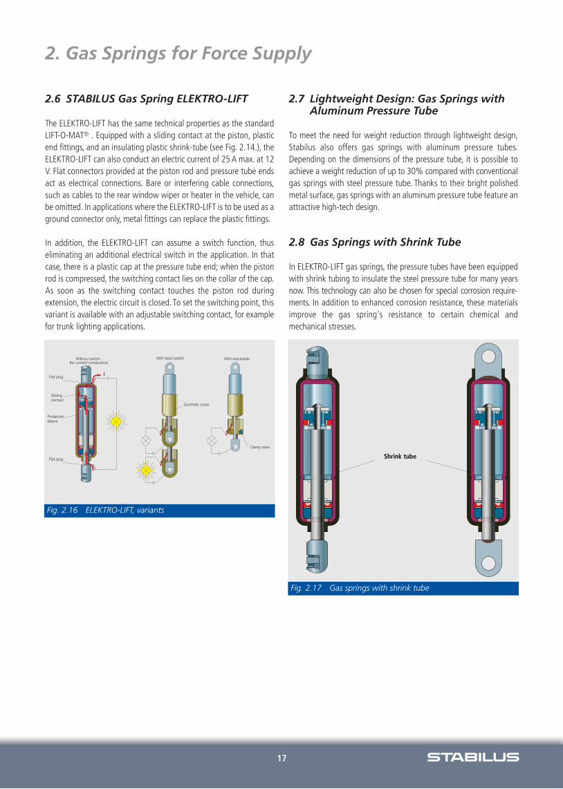
The ELEKTRO-LIFT has the same technical properties as the standardLIFT-O-MAT® . Equipped with a sliding contact at the piston, plasticend fittings, and an insulating plastic shrink-tube (see Fig. 2.14.), theELEKTRO-LIFT can also conduct an electric current of 25 A max. at 12V. Flat connectors provided at the piston rod and pressure tube endsact as electrical connections. Bare or interfering cable connections,such as cables to the rear window wiper or heater in the vehicle, canbe omitted. In applications where the ELEKTRO-LIFT is to be used as aground connector only, metal fittings can replace the plastic fittings.
In addition, the ELEKTRO-LIFT can assume a switch function, thus eliminating an additional electrical switch in the application. In that case, there is a plastic cap at the pressure tube end; when the pistonrod is compressed, the switching contact lies on the collar of the cap.As soon as the switching contact touches the piston rod during extension, the electric circuit is closed. To set the switching point, thisvariant is available with an adjustable switching contact, for examplefor trunk lighting applications.
2.7 Lightweight Design: Gas Springs with Aluminum Pressure Tube
To meet the need for weight reduction through lightweight design,Stabilus also offers gas springs with aluminum pressure tubes.Depending on the dimensions of the pressure tube, it is possible toachieve a weight reduction of up to 30% compared with conventionalgas springs with steel pressure tube. Thanks to their bright polishedmetal surface, gas springs with an aluminum pressure tube feature anattractive high-tech design.
2.8 Gas Springs with Shrink Tube
In ELEKTRO-LIFT gas springs, the pressure tubes have been equippedwith shrink tubing to insulate the steel pressure tube for many yearsnow. This technology can also be chosen for special corrosion require-ments. In addition to enhanced corrosion resistance, these materialsimprove the gas spring's resistance to certain chemical and mechanical stresses.
Fig. 2.16 ELEKTRO-LIFT, variants
Fig. 2.17 Gas springs with shrink tube

18
2. Gas Springs for Force Supply
2.9 Tips on Installation and Use
As described in Fig. 2.5, the gas spring should be installed preferablywith the piston rod pointing down, to ensure continuous lubricationof the seal with the lubricant accumulating in the seal.
If the gas spring is installed at a slope, the maximum slope dependson the oil fill amount. In that case, please notify us of the mountingorientation of the gas spring in your application. If the gas spring pivots around the horizontal during adjustment, the mounting orientation of the gas spring depends on the most frequent application end position.
In this application case, the gas spring should be equipped with an oilchamber system. If the piston rod points permanently upward in theapplication, a STABILUS gas spring with a double seal system shall beused.
Transverse forces may result in the premature wear of the gas spring.The mounting and actuation of the gas spring should therefore be freeof transverse forces. If the gas spring needs to move in a 3-dimensional plane, ball joints (see Fig. 2.6) can be used as connecting elements to prevent jamming.
The design of the standard gas spring is chosen so it can be used inambient temperatures of -30°C to +80°C. A brief exposure to 110°(max. 1 hour) is permissible. The gas spring is maintenance-free.
When mounting and operating the gas spring, please make sure thatthe piston rod in particular is protected from contaminants, paint, anddamage. We have prepared a directive for the disposal of gas springs,which you can order. Please also follow our tips and hints on the correct installation of gas springs, which can be found in our Comprehensive Gas Spring Catalog, as well as on the Internet at www.stabilus.de

19
3. Gas Springs for Force Supply andVariable Position Lock
In addition to the above mentioned functional characteristics of theLIFT-O-MAT® gas spring, such as adjustment and damping, locking gassprings have the added property of infinitely variable position locks.
This property is achieved with a small-sized, integrated valve systemto maintain the compact design of the gas spring. There are two basictypes of locking gas springs. Fig. 3.1 provides an overview and showsthe major areas of application.
3.1 STABILUS Gas Spring BLOC-O-LIFT®
The theoretical principle of the BLOC-O-LIFT® gas spring was explained in Chapter 1. The structure and specialty of the BLOC-O-LIFT® gas spring is shown in Fig. 3.2. In the piston, a valvecan be used to separate the two pressure chambers to the left and theright of the piston in a gas leak-proof manner. If the valve is openedby tappet actuation, the BLOC-O-LIFT® acts like a LIFT-O-MAT® gasspring and provides force supply:
The piston rod extends, damped by the gas spring force, or it can becompressed against the force of the gas spring. As soon as the valvetappet is released from the outside, the valve pin closes automaticallydue to the gas pressure acting on it. The gas exchange between pressure chamber 1 and 2 is interrupted and the piston or piston rodof the BLOC-O-LIFT® gas spring is locked.This way, BLOC-O-LIFT® canbe locked in any stroke position.
Further criteria for locking gas springs, which need to be customizedfor the respective application, are, in addition to the extension force - Actuation force - Actuation range- Damping- Locking characteristics (spring-locking or rigid)
3.2 Valve Actuation Range and DampingIn addition to the BLOC-O-LIFT® spring characteristic curve shown inFig. 3.2, there is also a valve force characteristic curve. The valve actuation force depends on the diameters of the piston rod, the valvepin, as well as the filling pressure of the gas spring. Since the diameter of the valve pin is the same, different piston rod diametersresult in different actuation forces. For devices with a 10-mm pistonrod diameter, they are approximately 20%; for devices with an 8-mmpiston rod diameter, they are approx. 30% of the extension force ofthe gas spring. The actuation range depends on the design of the valve system and ranges from 1 to 2.5 mm (see Chapter 3.3).
The extension speed of the piston rod and the damping can be specifiedin the BLOC-O-LIFT® with different diameters of the nozzle bore in thepiston. The BLOC-O-LIFT® shown in Fig. 3.2 should be installed withthe piston rod pointing down, to allow the lubricant in the device tocollect in the seal. If a gas spring is equipped with a double seal system similar to Fig. 3.4, it can be used in any mounting position.
Fig. 3.1 Overview of locking gas springs from STABILUS
Fig. 3.2 BLOC-O-LIFT®, structure, valve function, and springcharacteristic curve

20
3. Gas Springs for Force Supply andVariable Position Lock
3.3 BLOC-O-LIFT® Standard Actuation Basically, there are two different valve designs: the sliding valve andthe seat valve. Both types are shown in Fig. 3.3.
Sliding Valve The sliding valve is used in devices with standard actuation. The actuation range for opening the valve is a maximum of 2.5 mm. Thisdesign is resistant to pressure and tension; that is, the valve remainsclosed even when subjected to external pressure and tensile forcesfrom the application.
Seat Valve The advantage of this type lies in the very short actuation range (max. 1 mm) for opening the valve, which responds immediately whenactuated and releases or locks the gas spring. Like the seat valve, thesliding valve is pressure-resistant. When subjected to high tensile forces, it opens, because due to the shape of the valve pin, the pressuredarea at the valve seat increases relative to the valve shaft area.
3.4 Locking Characteristics of BLOC-O-LIFT® Gas Springs Depending on the application, rigid or spring-locking can be used.These characteristics can be achieved with the right structure of BLOC-O-LIFT® gas springs. When rigid-locking is chosen, the lockingdirection can be chosen as well. Furthermore, one differentiates between position-dependent and position-independent types.
3.4.1 BLOC-O-LIFT®, Spring-LockingIn certain applications, for example in the backrest adjustment of swivel chairs, springy, flexible locking is desirable. Fig. 3.4 shows aspring-locking BLOC-O-LIFT® gas spring. Because the filling gas canbe compressed, a spring effect results even when the valve is closed.
First, the piston rod can be pushed in easily, but after a few minutes,it becomes harder to compress it against the increasing gas pressure.This physical effect can be compared to the function of an air pumpwith the air pump valve closed. Because of the filling pressure of thegas spring, the stroke of the gas spring with a closed valve is muchsmaller than the air pump stroke. The relative deflection of the spring
under external load depends on the extension force of the gas spring,the piston rod diameter, and the respective position of the locked piston in the pressure tube. If the piston is near the pressure tube closed end, there will be a small deflection in the compressed direction and a comparatively large deflection in the extension direction. If the piston is locked in the medium range of the stroke, thespring compression and extension deflection will be the same.
3.4.2 BLOC-O-LIFT®, Rigid-LockingIn numerous applications, for example in steering column adjustmentor backrest adjustment in cars, rigid-locking is absolutely necessary. Inprinciple, rigid-locking could be achieved by filling the pressure tubewith oil that cannot be compressed. However, since the volume of thepiston rod to be pushed in has to be displaced, the gas spring cannotbe filled completely with oil; a certain gas volume must remain.
If the BLOC-O-LIFT® gas spring is installed with the piston rod pointing down, oil will collect above the piston because of gravity.However, if the piston rod cannot be mounted pointing down, a separating piston will ensure functional positioning of the oil. The resulting two types are explained hereafter:
3.4.3 BLOC-O-LIFT®, Position-Independent, Rigid-LockingIf the application is to remain rigidly locked when subjected to high external loads, rigid-locking BLOC-O-LIFT® gas springs are used. In thiscase, BLOC-O-LIFT® is equipped with a separating piston that separates the gas and oil chambers.
Whereas the gas chamber compensates the compressed piston rod volume and the oil expansion caused by the heat, the oil enables rigidlocking. The separating piston can be placed as shown in Fig. 3.5,either on the piston rod or between piston and pressure tube end.In both cases, the working chamber of the piston is filled completelywith oil. Since oil cannot be compressed, variant I is rigid in compressiondirection, variant II is rigid in extension direction when the valve is closed (see Fig. 3.5).
The maximum permissible oil locking force depends on the extensionforce of the gas spring and the device strength, taking into consideration all required safety factors.
Fig. 3.3 BLOC-O-LIFT® standard and short actuation Fig. 3.4 BLOC-O-LIFT®, spring-locking with double seal

21
3. Gas Springs for Force Supply andVariable Position Lock
If the piston is charged in the direction of the gas chamber while the valve is closed (variant I in extension direction, variant II in compressiondirection), then the BLOC-O-LIFT® is rigidly locked in this adjustment direction up to the respective gas locking force.Higher external forces willresult in piston rod deflection, because the separating piston is displaceddue to the external load and the gas volume is compressed. The gaslocking force varies with extension force F1 and the charging pressure ofthe gas spring.The gas locking force/extension force ratio corresponds tothe ratio of the separating piston/ piston rod cross-section; for design type I, it is approximately 4.5, for design type II, approximately 5.5. Bothgas spring types can be used in any mounting orientation.While variantII does not require additional design elements for this purpose, variant Iis equipped with the STABILUS double seal system,also shown in Fig.3.5.
3.4.4 BLOC-O-LIFT®, Position-Dependent, Rigid-LockingIt is possible to achieve the function of the variant described in Fig. 3.5less expensively, if the BLOC-O-LIFT® can be mounted in the application as shown in Fig. 3.6. Here, additional construction elements (e.g., separating piston) can be omitted.
If the gas spring is mounted with the piston rod pointing down, the oilin the device collects under the piston. This gas spring can then belocked rigidly in extension direction, as long as the piston is coveredwith oil. If the piston rod is pointed up, the gas spring can be lockedrigidly in compression direction.
If the opposite load is applied to the BLOC-O-LIFT®, the piston rod willdeflect when the external load exceeds the gas locking force. The oiland gas locking forces of these variants correspond to those deviceswith position-independent mounting orientation. Both variants can al-so be mounted at an incline. However, in this case, the adjustment ran-ge where the piston is covered with oil is smaller than when the gasspring is installed vertically. Thus, BLOC-O-LIFT® can only be locked ri-gidly in this limited stroke range. In addition, gas spring is equippedwith a double seal system for lubrication of the piston rod seal.
Fig. 3.5 BLOC-O-LIFT®, position-independent, rigid-locking inextension or compression direction
Fig. 3.6 BLOC-O-LIFT®, position-specific, rigid-locking inextension or compression direction

22
3. Gas Springs for Force Supply andVariable Position Lock
3.5 Tips on Installation and UseThe notes in chapter 2.4 on the LIFT-O-MAT® also apply to the BLOC-O-LIFT® gas spring.The device description contains instructionson the installation position due to the different locking functions.
If oil-locking gas springs (see Chapter 3.4.2) are used in changing ambient temperatures, care should be taken that the gas spring canmove freely on one end according to the thermal expansion of the oil,even when the gas spring is locked. A load on the gas spring beyondthe locking force can result in destruction or malfunction of the spring.BLOC-O-LIFT® is locked safely when there is little play between the outer actuation system and the valve tappet while the valve is locked.To unlock the device, the valve tappet should be pushed in by the amount indicated on the gas spring drawing. The maximum valve stroke depends on the device design and is indicated in the gas springdrawing.
3.6 Stabilus Gas Springs STAB-O-MAT® and STAB-O-BLOC®
STAB-O-MAT® and STAB-O-BLOC® are spring-locking gas springsused in swivel chairs for suspension, variable locking, and dampedheight adjustment, even under eccentric loads. For this purpose, thepressure tube or the support tube of these devices are dimensioned toaccommodate the transfer of bending moments. For both gas springs,the locking valve is located on the pressure tube end, as shown in Fig.3.7. For this reason, a guide tube is necessary, which forms an annu-lar gap between its outer diameter and the pressure tube inner diameter. The guide tube is located between the valve body and theseal and guide element. This pressure and guide tube combination ofa gas spring is also called a double tube system. The piston of the STAB-O-MAT® or STAB-O-BLOC® is closed.
When the valve is open and the piston rod pushed in, the gas frompressure chamber 2 can flow through the annular gap into pressurechamber 1.With the valve closed, the spring deflection and the springcharacteristics during extension and compression of the piston rod correspond to those of the spring-locked BLOC-O-LIFT® (s. Chap. 3.1.1).The extension force of the STAB-O-MAT® and STAB-O-BLOC® in theswivel chair application is usually between 300 N and 400 N.The dam-ping effect during compression and extension is determined by thechoice of the nozzle bore diameter.
The difference between these two locking gas springs lies in their structure.The STAB-O-MAT® absorbs the loads resulting from the weighton the seat and bending moments (caused by uneven weight distribu-tion on the seat) with the properly designed pressure tube; in the STAB-O-BLOC®, the functions of "suspension, damping, and adjusting"are performed by the internal pressure tube and the "transmission of bending moment" by the outer support tube.
Because of these properties, the STAB-O-MAT® is considered "self-supporting" and the STAB-O-BLOC® is "non-self-supporting." Thecombination of STAB-O-BLOC® with support tube is called "STAB-O-BLOC® Telescope." The STAB-O-BLOC® can be fastened in thesupport tube with a screw cap. This way, it can easily be replaced withother extension force variations, without having to change the supporttube, which is fastened to the seat carrier.The strength of the taper at theend of the pressure or support tube, which is clamped into the seat carrier of the swivel chair, determines the bending moment that can betransmitted.STABILUS tapers are designed for reversed bending momentsof up to 240 Nm (acc. to DIN 4550 and 4551). The permissible reversedbending stress for the respective taper dimensions can be found in theSTABILUS gas spring product line catalog.
STAB-O-MAT® and STAB-O-BLOC® Telescope are available with the same forces and dimensions, so that they are interchangeable. The extended length of gas springs in standard devices is between 320 mmand 700 mm, with strokes ranging from 90 mm to 265 mm.
Fig. 3.7 STAB-O-MAT® and STAB-O-BLOC® structures

23
3. Gas Springs for Force Supply andVariable Position Lock
The connection geometry at the piston rod end is designed for the devices to be fastened to an outer tube, together with an axial ball bearing (see Fig. 3.8).
3.6.1 STAB-O-MAT® and STAB-O-BLOC® Valve AssembliesThe valve body of the STAB-O-MAT® and STAB-O-BLOC® can be equipped with a sliding or seat valve (compare BLOC-O-LIFT® Fig. 3.6).This will result in different valve strokes or actuation ranges and forces for releasing the gas spring. The following table 3.1 shows allactuation variations.
The standard tappet height (see Fig. 3.7) is 6.0 mm for the STAB-O-BLOC®, 6.5 mm for the STAB-O-MAT® gas springs.To limit theplay between the release mechanism in the seat carrier and the actuator pin of the gas spring, all actuator variants are available with anadjustable tappet (can be set with a screw).
3.6.2 STAB-O-MAT® and STAB-O-BLOC® Columns STAB-O-MAT® and STAB-O-BLOC® Telescope and an outer tube arecombined into a swivel chair column. Fig. 3.8 shows a gas spring column with a standard outer tube, with the gas spring shown in thecompressed and extended position.
A taper at the outer tube end ensures easy mounting and safe attachment of the gas spring columns to the star base of the swivelchair.The STAB-O-MAT® and STAB-O-BLOC® Telescope are secured tothe outer tube with a safety clamp at the piston rod end. The pressureor support tube end is then pointed up, for fastening to the respectiveopposite taper of the seat carrier. The valve tappet is easily accessiblefor the release systems on the seat carrier. In the compression directionof the gas spring, the external load is supported by the axial ball bearing secured to the end of the piston rod, which simultaneously ensures a slight rotation of the seat carrier. In the one-piece version,the bearing is a captive unit, thus contributing to easy installation orremoval of the gas spring.The rubber cushion positioned between thepressure tube end and the axial bearing is a soft stop in the lowest seatposition, when the gas spring is compressed and cannot deflect anyfurther. For optimized guidance when adjusting and swiveling the gasspring or the seat carrier, the outer tube has a fitted guide bushing.Thelength of this bushing is designed to transmit the bending momentsthat are led into the pressure or support tube safely to the outer tube.The stroke and extended length of the gas spring, as well as the lengthof the outer tube, must therefore be matched.The piston rod of the gasspring is then free from transverse forces and bending moments. Therequired guided length of the gas spring when extended (see Fig. 3.8)depends on the gas spring stroke. The effective length should be atleast 70 mm.
Additional column versions are available to increase the ease of gasspring adjustment and bounce properties of the swivel chair; they aredescribed in the following sections.
Table 3.1 Valve and Actuation Variations
Fig. 3.8 STAB-O-MAT® and STAB-O-BLOC® columns,structures with standard outer tube

24
3. Gas Springs for Force Supply andVariable Position Lock
3.6.3 STABILUS Outer Tube with Bottom Spring Special seating comfort can be achieved if, in addition to a rubber cushion, a coil compression spring (shown in Fig. 3.9) is integrated inthe outer tube. This spring is connected to the piston rod of the gasspring via flexible coupling.
If the piston rod is compressed and the gas spring cannot deflect further, a coil compression spring provides an additional bottom springfunction. In all other stroke positions of the gas spring, the gas springand the coil compression spring act together, which ensures pleasantresilience when the gas spring is locked. As an alternative to the coilspring, special end position buffers can be used, which also offer more comfort in the lowest seat position.
3.6.4 STABILUS Telescope Outer TubeThe height adjustment of STAB-O-MAT® and STAB-O-BLOC® gassprings is usually limited by the required guided length in the outer tube. An increased adjustment range automatically results in a longerouter tube, thus causing the lowest seat position to be higher.
The STABILUS Telescope Outer Tube solves this problem. For this purpose,a telescoping tube is integrated in the outer tube.While the gas springis guided in the telescope tube, the telescope tube is guided in the outer tube (see Fig. 3.10). It extends as soon as the pin on the gasspring reaches the guide bushing during adjustment of the gas spring.
3.6.5 Multi-Function ColumnIt is not always desirable that swivel chairs remain at the set height,but return to a certain position upon removal of the load. The MULTI-FUNCTION COLUMN not only returns to the highest seat position, but also swivels back to the starting position.This ensures anappearance of "neatness" at all times. Naturally, all other functions ofvariable seat adjustment are still available in the MULTI-FUNCTIONCOLUMN. The MULTI-FUNCTION COLUMN is especially suited for conference room chairs and special chair applications, for example intheGerman Parliament in Berlin or the European Parliament in Strasbourg.
Fig. 3.10 STABILUS swivel chair column with standard andtelescope outer tube, structure
Fig. 3.11 Multi-function column NEW
Fig. 3.9 STABILUS swivel chair column with bottom spring

25
3. Gas Springs for Force Supply andVariable Position Lock
3.6.6 Non-Twisting ColumnIn certain applications, swivel chairs should not turn, either due to thesituations or facilities they are used in. This can be ensured with non-twisting columns. At the same time, all advantages and the fullcomfort of the variable locking height adjustment functions of theSTAB-O-MAT® and STAB-O-BLOC® columns are available.
3.6.7 Column with Additional Stop FunctionThe telescope column with stroke-controlled stop function protectsstools and task chairs for standing/seated workstations in a specificrange against accidental rolling away.Above a defined actuation pointwithin the stroke range, a rubber stopper rebounds out of the columnwhen a load is applied by the user of the chair, thus preventing thechair from rolling away. Below this actuation point, the stopper remains in and the chair can be used and adjusted like a normal swivel chair.
3.6.8 Tips on Installation and UseThe mounting orientation of the STAB-O-MAT® and STAB-O-BLOC®
Telescope is determined by the respective end fittings.The taper at thepressure or support tube end is attached to the opposite taper of theseat carrier. The outer tube taper is installed in the respective opposite taper of the star base.The piston rod of the gas spring shouldalways point down. Please follow the strength classes and taper dimensions given in the STABILUS Gas Spring Catalog, as well as therespective standards (e.g., DIN 4551 for office swivel chairs in Germany).To protect the piston rod from transverse force and bending momentloads or jamming, the pressure tube of the gas spring shall be properlyguided in the guide bushing of the outer tube. The piston rod end isattached to the outer tube bottom, allowing for some radial play.Whenusing STABILUS gas spring columns, both are automatically guaranteed.
When mounting the multi-part axial bearings, the assembly sequenceaccording to the drawing shall be followed. The swivel chair can thenbe swiveled noiselessly and comfortably. For further application hintssee Chap. 2.9.
3.7 STABILUS Actuation Systems for Locking Gas SpringsThe actuation system consists of an actuation element, for example onthe seat carrier, the release head on the gas spring, and – for "remote control" – a Bowden cable as the transmission element between actuation element and release head. The choice of actuationelement is usually determined by the free installation space and thecustomer's wishes regarding form and function.
The various types of STABILUS release heads are shown in Fig. 3.13.Also shown is a universal actuation element for BLOC-O-LIFT® gassprings.
The release head or valve tappet of the BLOC-O-LIFT® gas spring canbe operated by release lever or Bowden cable. Both release head types are screwed onto the piston rod and secured with a nut. They also contain the piston rod-side connection to the application, whichallows for a compact design and easy installation of the gas spring.The Bowden cable is installed by placing the sleeve on the jib of theactuation head.
The design of the release head of the STAB-O-BLOC® / STAB-O-MAT®
gas spring is designed to include the release head in the pressure tube taper. It can be removed any time by releasing the fasteningclamps.The lever and Bowden cable lengths depend on the respectiveapplication. Dimensions, strengths, and installation tips for the actuation systems are included in the STABILUS specifications.Depending on the installation situation, radial guidance of the Bowden cable might be more favorable. There is a special configuration available for this as well.
Fig. 3.13 Stabilus release heads and actuation element
Fig. 3.12. Column with additional stop function NEW
26
4. STABILUS Locking Elements without ExtensionForce: HYDRO-BLOC®
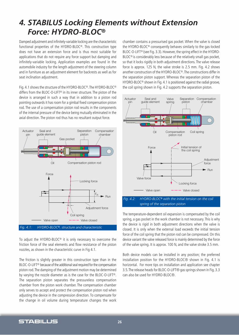
Damped adjustment and infinitely-variable locking are the characteristicfunctional properties of the HYDRO-BLOC®. This construction typedoes not have an extension force and is thus most suitable for applications that do not require any force support but damping andinfinitely-variable locking. Application examples are found in the automobile industry for the length adjustment of the steering columnand in furniture as an adjustment element for backrests as well as forseat inclination adjustment.
Fig. 4.1 shows the structure of the HYDRO-BLOC®.The HYDRO-BLOC®
differs from the BLOC-O-LIFT® in its inner structure. The piston of thedevice is arranged in such a way that in addition to a piston rod pointing outwards it has room for a gimbal fixed compensation pistonrod. The use of a compensation piston rod results in the componentsof the internal pressure of the device being mutually eliminated in theaxial direction. The piston rod thus has no resultant output force.
To adjust the HYDRO-BLOC® it is only necessary to overcome the friction force of the seal elements and flow resistance of the piston nozzles, as shown in the characteristic curve in Fig 4.1.
The friction is slightly greater in this construction type than in theBLOC-O-LIFT® because of the additional seal required for the compensationpiston rod.The damping of the adjustment motion may be determinedby varying the nozzle diameter as is the case for the BLOC-O-LIFT®.The separation piston separates the pressureless compensation chamber from the piston work chamber. The compensation chamberonly serves to accept and protect the compensation piston rod whenadjusting the device in the compression direction. To compensate forthe change in oil volume during temperature changes the work
chamber contains a pressurised gas pocket. When the valve is closedthe HYDRO-BLOC® consequently behaves similarly to the gas-lockedBLOC-O-LIFT® (see Fig. 3.3). However, the spring effect in the HYDRO-BLOC® is considerably less because of the relatively small gas pocket,so that it locks rigidly in both adjustment directions. The valve releaseforce is approx. 125 N, the valve stroke is 2.5 mm. Fig. 4.2 shows another construction of the HYDRO-BLOC®.The constructions differ inthe separation piston support. Whereas the separation piston of theHYDRO-BLOC® shown in Fig. 4.1 is positioned against the radial groove,the coil spring shown in Fig. 4.2 supports the separation piston.
The temperature-dependent oil expansion is compensated by the coilspring, a gas pocket in the work chamber is not necessary. This is whythe device is rigid in both adjustment directions when the valve is closed. It is only when the external load exceeds the initial tension force of the coil spring that the piston rod can be compressed. On thisdevice variant the valve released force is mainly determined by the forceof the valve spring. It is approx. 100 N, and the valve stroke 3.5 mm.
Both device models can be installed in any position; the preferred installation position for the HYDRO-BLOC® shown in Fig. 4.1 is horizontal. For more tips on installation and application see chapter3.5.The release heads for BLOC-O-LIFT® gas springs shown in Fig. 3.3can also be used for HYDRO-BLOC®.
Fig. 4.1: HYDRO-BLOC®, structure and characteristic
Fig. 4.2: HYDRO-BLOC® with the initial tension on the coilspring of the separation piston

27
5. Gas Spring Range and Mounting Situation
You can select your gas springs from the STABILUS gas spring type programmes. They include numerous variants related to stroke A,extended length B, thrust force F1 and connection techniques of theSTABILUS gas springs.
The determination of dimensions A and B required for the applicati-on as well as the necessary thrust force F1 of the gas spring occurs inmost cases by straightforward estimating techniques. A particularly comfortable opening and closing behaviour of the application is obtained when the required gas spring and its connection points areobtained by simulation calculation using the STABILUS mounting proposal programme.
5.1 Estimation of Extension Force F1
Fig. 5.1 gives a schematic representation of a random flap (e.g. a machine hood, cupboard door, loader ramp etc.) in opened and closedposition. All the dimensions and forces required for estimating techniques are listed.
The extended length B can be chosen in such a way that the gas springserves as a stop when opening the flap. The required minimum thrustA of the gas spring is then the result of the difference between the extended and compressed length E.
The stroke or the extended and compressed length can be graphicallyrepresented by measuring a correct scale drawing or using trigonometric functions. The gas spring stroke should also take into account the length tolerance of the application and gas spring.
Extension force F1 of the gas spring can be calculated on the basis ofthe moment balance on the application pivot bearing.The extension force is measured in such a way that the flap remainsopen. Moreover, force reserve factor R is included in the calculationequation in Fig. 5.1.
For R=1 the force balance is obtained from the weight force of application FG (in the centre of gravity) and of the thrust force of gasspring F1 . The flap is then suspended. The greater the selected forcereserve factor, the greater will be the "manual force" required to close the application.
As a general rule the force reserve factor is of between 1.2 and 1.3.For ambient temperatures of more than 30°C R may be smaller, for ambient temperatures of less than 10°C R should be greater (seeChap. 1.2.2).The rigidity and weight of the application determine num-ber n of the required gas springs. Large, flexible flaps usually requiretwo gas springs to prevent the tilting or sagging of the application.
5.2 Calculation of the Manual Force Characteristic,Simulation, Calculation
To assess or optimize the adjustment function of an application the extent of the necessary manual forces is considered over the full adjustment range of the application. The manual force characteristicfor opening and closing the application can be determined through simulation in the STABILUS mounting proposal programme.
The goal of the simulation calculation is to obtain the optimal arrangement of the gas spring or extension force and spring characteristic in combination with the optimal connection points in theapplication. The optimum depends on the relevant function. For instance gas springs in vehicle tailgates are measured to ensure thatthe application requires no further manual force once the applicationhas opened slightly and that during closing the tailgate automaticallysnaps in the lock.
Other applications require the immediate opening or extension of thegas spring (e.g. swivel chair-backrest), other applications must bemaintained in a specific position (e.g. top part of a sun bed etc.). Allthese different requirements can be represented in the manual forcebehaviour. The drafting of a mounting proposal is done by STABILUSor STABILUS agents.
Fig. 5.1: Stroke and extension force of a gas spring to open aflap

28
5. Gas Spring Range and Mounting Situation
The necessary indications for processing the mounting proposal of anapplication with a rotating joint are given in drawing SK 0902FP in annex 6.2. If the application is activated with a four-bar hinge, theplans are also required in addition to the geometrical description ofthe fourbar hinge.
Fig. 5.2 shows the result of the simulation calculation based on the example of an application drawing from Fig. 5.1. The left side of thepicture shows the kinematic representation of the application. The elements and forces used are numbered.
Rod 2 is used as a replacement representation of the tailgate and isconnected to the pivot bearing.The tailgate is represented in open andclosed condition, the suspension angle on the bearing is of 90°. Thegas spring as shown as element 3 in which the position of the gasspring connections are marked by circles on the piston rod and pressure tube. In addition to the components of the application, theoperating forces such as the weight force of tailgate FG (4) and ma-nual force FH (5) for opening and closing the flap are shown accordingto their position and direction.
The paths in which these forces act over the full range of the applicationare represented as arcs.The manual forces for opening and closing theapplication can be calculated at different positions along the arc. Themanual force characteristics of the application are shown on the rightside of the picture in Fig. 5.2. The characteristics are identified by characters and the legend is located in the top picture corner.
At the origin of the abscissa (0°-opening angle) the flap is closed, thegas spring is compressed. Positive manual forces mean that the application requires that manual force be applied to achieve adjustment.For negative manual forces the moment of the gas spring is sufficiently large such that the application can adjust automatically.
In the example (see Fig. 5.2) manual force characteristic E indicatesthe opening behaviour of the flap at nominal F1 and at an ambient temperature of the gas spring.To open the flap from a closed positionthe manual force is initially of approx. 45 N. During the further opening process the manual force decreases gradually, because of theincreasing lever action of the gas spring, until the intersection pointwith the abscissa (approx. 20° opening angle) is reached.As from thispoint the manual force becomes negative.
The flap now opens now automatically up to the stop (90° openingangle). Manual characteristic B describes the closing process from anopen position of the application (90° opening angle). Hence some 33Nmanual force are required to start the closing process of the flap.After the intersection of the characteristic with the abscissa the manual force becomes negative, so that the flap automatically falls inthe lock.The intersection of the characteristic with the abscissa is main-ly dependent on the connection points of the gas spring, thrust forceF1 and spring characteristic x as well as on the ambient temperatureof the application.
The example in Fig. 5.2 shows the characteristics at 80°C and -30°Cin addition to the manual force characteristic at ambient temperature.These characteristics also take into account the tolerance of extensionforce F1 of the gas spring, so that he minimum and maximum manualforces of the application can be illustrated off. The manual force at thestart of characteristic C (90° opening angle) is also called the "holdingforce" of the application, because it represents the force reserve forholding the flap open at the lowest ambient temperature (here: -30°C)and bottom extension force tolerance. The force reserve should be atleast 45 N. The values on which this example is based are listed in thedata sheet of the mounting proposal (see Fig. 5.3).
Fig. 5.2: Result of the simulation calculation, kinematic andmanual force characteristics

29
5. Gas Spring Range and Mounting Situation
The performance characteristics of the STABILUS mountingproposal programme are briefly summarised below:- Variation of the connection positions of the gas springs,- Variation in the extension force and hysteresis,- Variation of the spring characteristic,- Random characteristic (linear, degressive, progressive),- Calculation of random constructions of single and four-bar hinge
systems,- Compliance with building length tolerances,- Compliance with force tolerances,- Compliance with the operating temperature range.
For requests concerning the drafting of a mounting proposal pleaserefer to drawing 10014184 in annex 6.2.
Fig. 5.3: Data sheet of the STABILUS mounting proposalprogramme
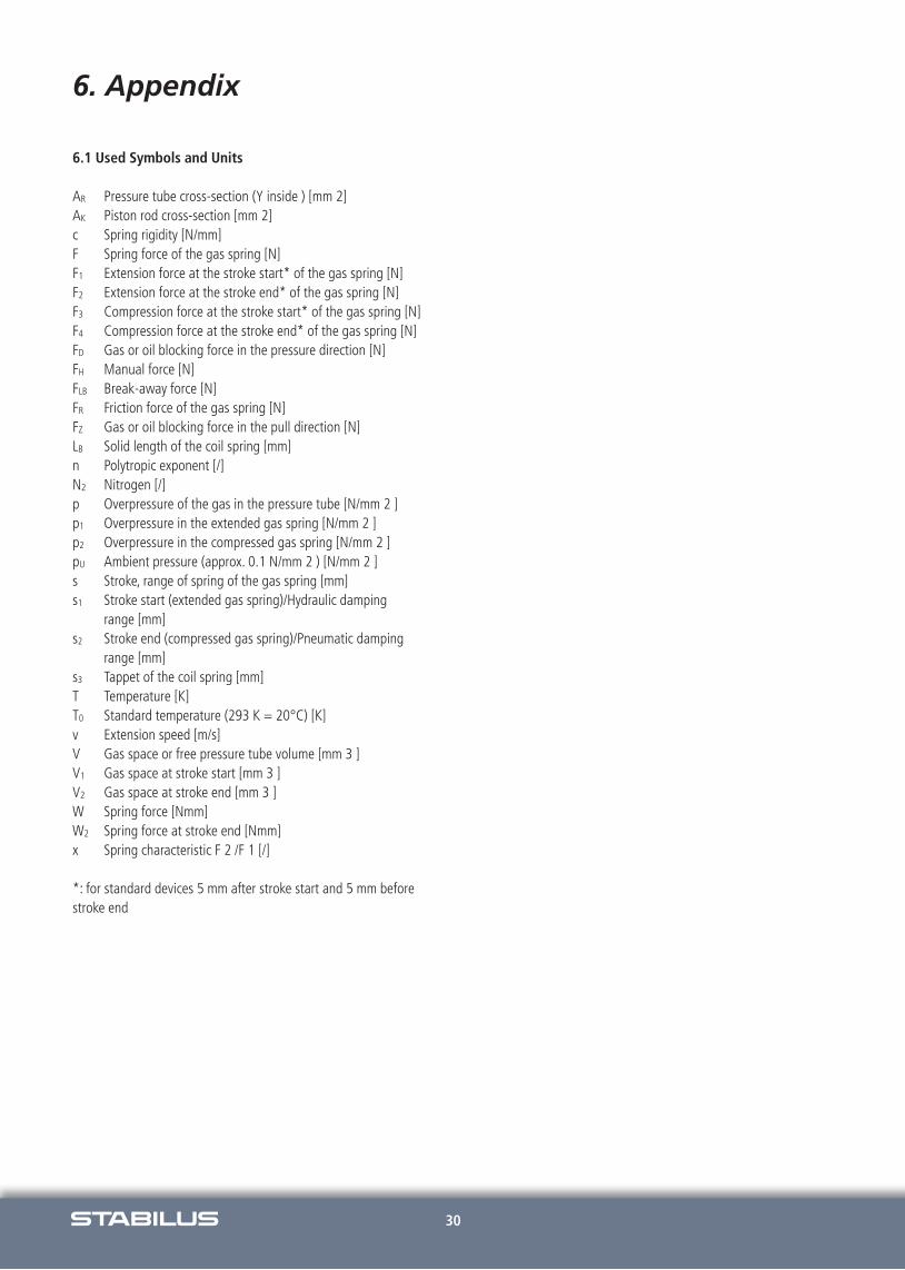
30
6. Appendix
6.1 Used Symbols and Units
AR Pressure tube cross-section (Y inside ) [mm 2]AK Piston rod cross-section [mm 2]c Spring rigidity [N/mm]F Spring force of the gas spring [N]F1 Extension force at the stroke start* of the gas spring [N]F2 Extension force at the stroke end* of the gas spring [N]F3 Compression force at the stroke start* of the gas spring [N]F4 Compression force at the stroke end* of the gas spring [N]FD Gas or oil blocking force in the pressure direction [N]FH Manual force [N]FLB Break-away force [N]FR Friction force of the gas spring [N]FZ Gas or oil blocking force in the pull direction [N]LB Solid length of the coil spring [mm]n Polytropic exponent [/]N2 Nitrogen [/]p Overpressure of the gas in the pressure tube [N/mm 2 ]p1 Overpressure in the extended gas spring [N/mm 2 ]p2 Overpressure in the compressed gas spring [N/mm 2 ]pU Ambient pressure (approx. 0.1 N/mm 2 ) [N/mm 2 ]s Stroke, range of spring of the gas spring [mm]s1 Stroke start (extended gas spring)/Hydraulic damping
range [mm]s2 Stroke end (compressed gas spring)/Pneumatic damping
range [mm]s3 Tappet of the coil spring [mm]T Temperature [K]T0 Standard temperature (293 K = 20°C) [K]v Extension speed [m/s]V Gas space or free pressure tube volume [mm 3 ]V1 Gas space at stroke start [mm 3 ]V2 Gas space at stroke end [mm 3 ]W Spring force [Nmm]W2 Spring force at stroke end [Nmm]x Spring characteristic F 2 /F 1 [/]
*: for standard devices 5 mm after stroke start and 5 mm beforestroke end
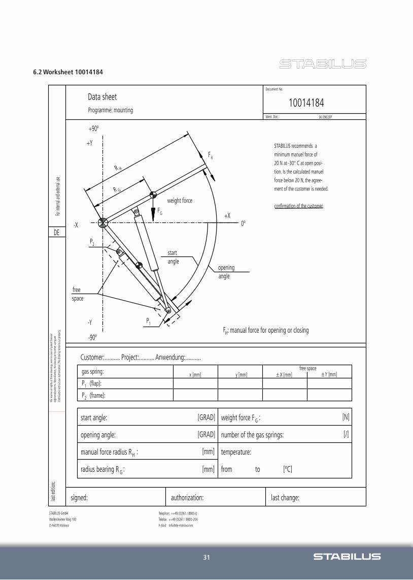
31
6.2 Worksheet 10014184

w w w. S TA B I L U S . c o mw w w. s t a b i l u s . c o m
A u s t r a l i a
S t a b i l u s P t y . L t d .
6 5 R e d w o o d D r i v e
D i n g l e y , V I C 3 17 2
A u s t r a l i a
+ 6 1 3 9 5 5 2 -14 0 0
+ 6 1 3 9 5 5 2 -14 9 9
i n f o @ a u . s t a b i l u s . c o m
B r a s i l
S t a b i l u s L t d a .
A v . P r e s . Ta n c r e d o
d e A l m e i d a N e v e s , k m 1 , 2
C E P 3 7. 5 0 4 - 0 6 6 I t a j u b á ( M G )
B r a s i l
+ 5 5 3 5 3 6 2 9 - 5 0 0 0
+ 5 5 3 5 3 6 2 9 - 5 0 0
i n f o @ s t a b i l u s . c o m . b r
C h i n a
S t a b i l u s S a l e s O f f i c e S h a n g h a i
8 8 , K e Y u a n R o a d
U n i t N o 7 2 5
Z h a n g J i a n g H i - Te c h P a r k
P u d o n g , S h a n g h a i
P R C h i n a
+ 8 6 2 1 2 8 9 8 - 6 5 0 0
+ 8 6 2 1 2 8 9 8 - 6 510
i n f o @ c n . s t a b i l u s . c o m
C h i n a
S t a b i l u s J i a n g s u L t d .
L o n g X i a n g R o a d N o . 8
W u j i n H i - Te c h I n d u s t r i a l Z o n e ,
C h a n g z h o u C i t y ,
J i a n g s u P r o v i n c e , 2 13 16 4
P R C h i n a
i n f o @ c n . s t a b i l u s . c o m
D e u t s c h l a n d
S t a b i l u s G m b H
W a l l e r s h e i m e r W e g 10 0
5 6 0 7 0 K o b l e n z
G e r m a n y
+ 4 9 2 6 1 8 9 0 0 - 0
+ 4 9 2 6 1 8 9 0 0 - 2 0 4
i n f o @ d e . s t a b i l u s . c o m
E s p a ñ a
S t a b i l u s E s p a ñ a S . L .
B a r r i o A r e t x a l d e , 12 8
4 8 19 6 L e z a m a ( V i z c a y a )
E s p a ñ a
+ 3 4 9 4 4 5 5 - 4 17 0
+ 3 4 9 4 4 5 5 - 4 18 3 4
i n f o @ e s . s t a b i l u s . c o m
F r a n c e
S a l e s O f f i c e S a r l
L e Te c h n o p a r c , L ´ E s p a c e M é d i a
3 , r u e G u s t a v e E i f f e l
7 8 3 0 0 P o i s s y
F r a n c e
+ 3 3 13 9 2 2 6 4 9 4
+ 3 3 13 9 2 2 6 4 9 6
i n f o @ f r . s t a b i l u s . c o m
I t a l i a
S t a b i l u s S . r . l .
V i a N a z i o n a l e , 2 0 9
10 0 6 9 V i l l a r P e r o s a ( To )
I t a l y
+ 3 9 0 12 1 3 16 -7 11
+ 3 9 0 12 1 3 15 - 6 3 7
i n f o @ i t . s t a b i l u s . c o m
J a p a n
S t a b i l u s J a p a n C o r p o r a t i o n
Toshin 24 Shinyokohama, Bldg B-8F
2- 3 - 8 S h i n -Yo ko h a m a , Ko h o k u - k u
2 2 2 - 0 0 3 3 Yo k o h a m a
J a p a n
+ 8 1 4 5 4 7 1 - 2 9 7 0
+ 8 1 4 5 4 7 1 - 2 9 8 9
i n f o @ j p . s t a b i l u s . c o m
K o r e a
S t a b i l u s C o . L t d . S a l e s O f f i c e
S e o u l
3 F, W o o g a n g B l d g . , 4 0 2 - 3
Y u l j e o n - d o n g , C h a n g a n - g u
S u w o n - s i , G y e o n g g i - d o
K o r e a / Z i p C o d e 4 4 0 - 8 2 7
+ 8 2 3 1 2 9 8 -174 3
+ 8 2 3 1 2 9 8 - 0 74 2
i n f o @ k r . s t a b i l u s . c o m
M é x i c o
S t a b i l u s , S . A . d e C .V .
I n d u s t r i a M e t a l ú r g i c a N o . 10 10
P a r q u e I n d u s t r i a l R a m o s A r i z p e
C .P. 259 0 0 Ramos Ar izpe, Coahui la
M é x i c o
+ 5 2 8 4 4 4 11 - 0 7 0 7
+ 5 2 8 4 4 4 11 - 0 7 0 6
i n f o @ m x . s t a b i l u s . c o m
N e w Z e a l a n d
S t a b i l u s L i m i t e d
7 5 E l l i c e R d . G l e n f i e l d
P O B o x 10 10 2 3 N S M C
A u c k l a n d
N e w Z e a l a n d
+ 6 4 9 4 4 4 - 5 3 8 8
+ 6 4 9 4 4 4 - 5 3 8 6
i n f o @ s t a b i l u s . c o . n z
R o m a n i a
S T A B I L U S S . R . L . R o m a n i a
k m 5 + 9 0 0
( s o s e a u a B r a s o v - H a r m a n )
R O - 5 0 7 19 0 S a n p e t r u ,
B r a s o v R o m a n i a
+ 4 0 2 6 8 3 0 8 9 0 0
+ 4 0 7 2 9 5 0 0 4 3 6
+ 4 0 2 6 8 3 0 8 9 10
i n f o @ r o . s t a b i l u s . c o m
S i n g a p o r e
S t a b i l u s S i n g a p o r e S a l e s O f f i c e
c / o Z F S o u t h e a s t A s i a P t e . L t d .
11 Tu a s D r i v e 1
S i n g a p o r e 6 3 8 6 7 8
+ 6 5 6 4 2 4 8 7 2 6
+ 6 5 6 4 2 4 8 7 8 8
i n f o @ s g . s t a b i l u s . c o m
U n i t e d K i n g d o m
S t a b i l u s S a l e s O f f i c e
U n i t 4 , C a n a d a C l o s e
B a n b u r y , O x o n . O X 16 2 R T
E n g l a n d
+ 4 4 12 9 5 7 0 0 -10 0
+ 4 4 12 9 5 7 0 0 -10 6
i n f o @ u k . s t a b i l u s . c o m
U S A
S t a b i l u s I n c .
12 0 1 Tu l i p D r i v e
G a s t o n i a N C 2 8 0 5 2 - 18 9 8
U S A
+ + 1 7 0 4 8 6 5 -74 4 4
+ + 1 7 0 4 8 6 5 -7 7 8 1
i n f o @ u s . s t a b i l u s . c o m
U S A
S a l e s O f f i c e A u t o m o t i v e
3 6 2 2 5 M o u n d R o a d
St e r l i n g H e i g h t s , M I 4 8 310 - 47 3 9
U S A
+ + 1 5 8 6 9 7 7 - 2 9 5 0
+ + 1 5 8 6 4 4 6 - 3 9 2 0
i n f o @ u s . s t a b i l u s . c o m
U S A
S a l e s O f f i c e I n d u s t r i a l
9 19 N . P l u m G r o v e R o a d , S u i t e G
I L 6 0 17 3 S c h a u m b u r g , I l l i n o i s
U S A
+ + 1 8 4 7 517 - 2 9 8 0
+ + 1 8 4 7 517 - 2 9 8 7
i n f o @ u s . s t a b i l u s . c o m
P r o d u k t i o n
Ve r t r i e b s b ü r o
p r o d u c t i o n f a c i l i t i e s
r e p r e s e n t a t i v e s
Wor ldwide
30
00
/10
20
07
dp
art
ne
r.co
m N
ot
resp
on
sib
le f
or
typ
og
rap
hic
al
err
ors
.