liftline gas springs - suspa · liftline 3 contents design, functionality and features 4-5 suspa...
TRANSCRIPT

Liftline Gas SpringsStandard program, individual gas springs and special functions
www.suspa.com

2
Headquarters
Subsidiary
Agency
SUSPA - Your strong industrial partnerFor more than 50 years, SUSPA products have been present in your daily life - at home in furniture, refrigerators and washing machines, in means of transport like buses, trains and planes, in modern office furniture, in leisure and fitness equipment, but also in hospital beds and operating tables in hospitals and rehab centers.
Although you may not be able to see our products, we are always there – increasing the comfort and safety level for all of you.
Major players in the automobile, office furniture, industrial, transportation, appliance, health care, leisure, and gaming industries depend on SUSPA as a developmental and systems solution partner. Our engineers and technical sales team will work seamlessly with your staff on a wide variety of projects, committed to providing the most effective solution for your organization.
SUSPA’s worldwide sales and distribution network allows us to always be in touch with our customers — no matter where they are in the world! SUSPA has production facilities in Germany, the United States, China, India and the Czech Republic. This worldwide manufacturing capability gives SUSPA a competitive edge over other gas spring manufacturers.
Reliability as highest standardRequirements on quality are increasing in the automotive industry as well as in other industry sectors. SUSPA certifications according to TS16949 have therefore been an integral part for quite some time.
Effective quality management from purchasing to production and sales and on to final application secures the worldwide great reputation and reliability of SUSPA gas springs.
We test gas springs 100% according to our internal quality standard. Without any maintenance required, SUSPA gas springs normally achieve a service life of over 50,000 load cycles.

Liftline 33
Contents
Design, functionality and features 4-5
SUSPA ordering system 6
Standard program gas springs (Liftline)Gas springs dampened on extension of the 16-series
7-15
16-12 Ø tube 12 mm Ø piston rod 4 mm max. stroke 150 mm extension force 40-180 N 716-1 Ø tube 15 mm Ø piston rod 6 mm max. stroke 150 mm extension force 50-420 N 8-916-2 Ø tube 18.5 mm Ø piston rod 8 mm max. stroke 250 mm extension force 80-750 N 10-1116-4 Ø tube 22 mm Ø piston rod 10 mm max. stroke 495 mm extension force 100-1,200 N 12-1316-6 Ø tube 28 mm Ø piston rod 14 mm max. stroke 500 mm extension force 200-2,000 N 14-15
End fittingsClevis, fork heads, ball joints, angle plates
16-19
Assembly instructions 19
Special functionsTipUp® - opening system for storage beds, Soft-Stop, Positioning gas spring, Space-mat, TouchLift
20-22
Technical adviceStorage, handling, utilization and assembly
23
www.suspa.com/uk/products/gas-springs

4
Design and functionality of gas springs
Gas springs are hydropneumatic adjustment elements. They consist of a pressure tube plus piston rod with piston unit. Connecting elements on the pressure tube and the piston rod allow appropriate connection to your application.
At the core of the SUSPA gas spring is the special seal and guide system. This ensures hermetic sealing of the cavity with low friction, even under extreme environmental conditions.
The gas spring is filled with non-toxic nitrogen at high pressures. This produces a charging pressure that in turn exerts an effect on the cross section of the piston rod, generating the extension force.
If the extension force of the gas spring is greater than the force of the counterbalance, the piston rod extends; if the extension force is smaller, it retracts. The speed of the extension is determined by the flow cross section in the damping system.
In addition to nitrogen, the cavity contains a defined quantity of oil for lubrication and end position cushioning.
The cushioning effect of a gas spring can be determined depending on the requirements and the task involved.
Clevis
Sealing and guidance package
Piston assembly
Pneumatic medium
Clevis
Hydraulic medium
Pressure tube
Piston rod
How force and effective cushioning are produced
Piston assembly
Sealing and guidance package
Liftline 55
Features of gas springs
Liftline is an excellent gas spring progam offered by SUSPA. Successfully proven in the market for decades and always state-of-the art through constant innovation. The SUSPA Liftline program includes five basic types: the types 16-12, 16-1, 16-2, 16-4 and 16-6.
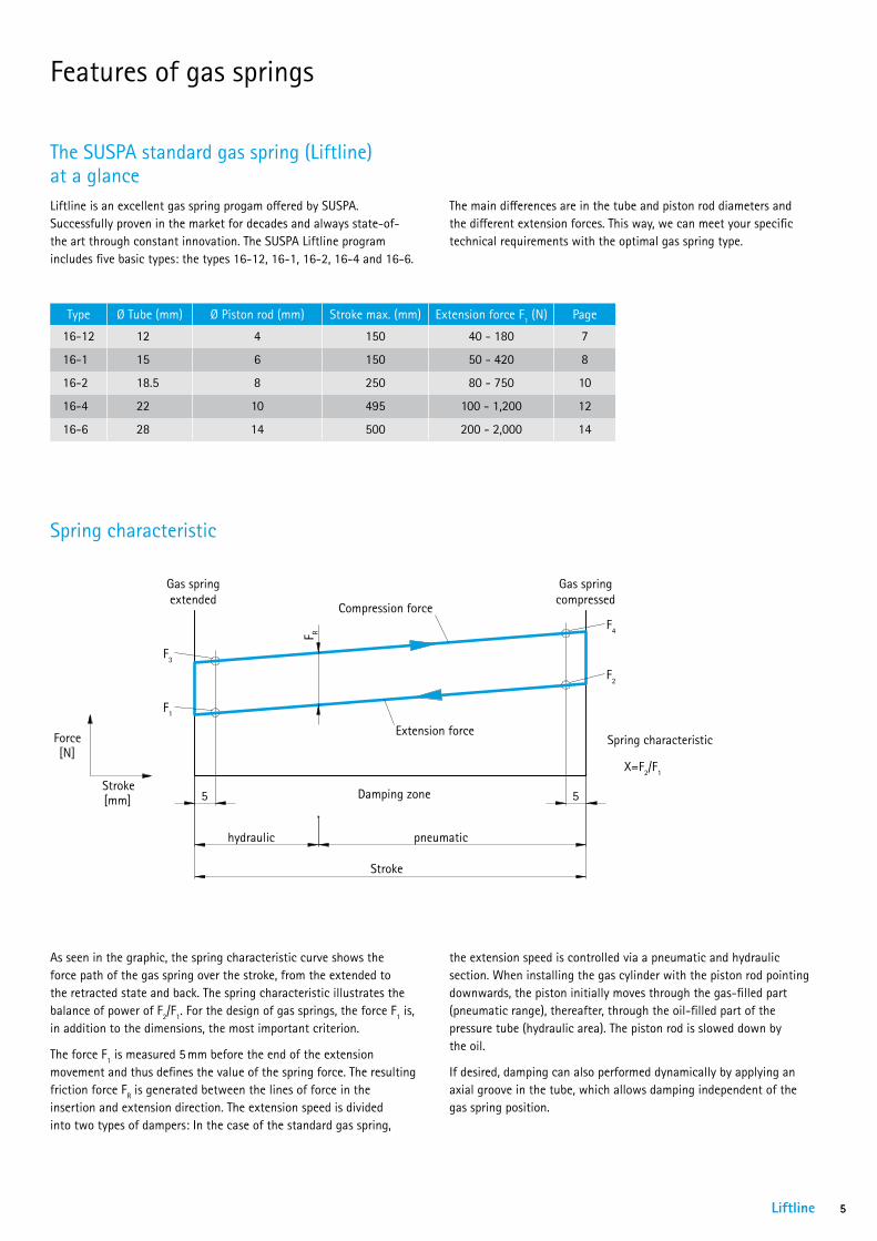
As seen in the graphic, the spring characteristic curve shows the force path of the gas spring over the stroke, from the extended to the retracted state and back. The spring characteristic illustrates the balance of power of F2/F1. For the design of gas springs, the force F1 is, in addition to the dimensions, the most important criterion.
The force F1 is measured 5 mm before the end of the extension movement and thus defines the value of the spring force. The resulting friction force FR is generated between the lines of force in the insertion and extension direction. The extension speed is divided into two types of dampers: In the case of the standard gas spring,
Spring characteristic
Type Ø Tube (mm) Ø Piston rod (mm) Stroke max. (mm) Extension force F1 (N) Page
16-12 12 4 150 40 - 180 7
16-1 15 6 150 50 - 420 8
16-2 18.5 8 250 80 - 750 10
16-4 22 10 495 100 - 1,200 12
16-6 28 14 500 200 - 2,000 14
The SUSPA standard gas spring (Liftline) at a glance
5 5
hydraulic pneumatic
Stroke
F1
F2
Force[N]
Stroke[mm]
Gas springextended
Gas springcompressed
Spring characteristic
X=F2/F1
Compression force
Extension force
Damping zone
F R
F3
F4
the extension speed is controlled via a pneumatic and hydraulic section. When installing the gas cylinder with the piston rod pointing downwards, the piston initially moves through the gas-filled part (pneumatic range), thereafter, through the oil-filled part of the pressure tube (hydraulic area). The piston rod is slowed down by the oil.
If desired, damping can also performed dynamically by applying an axial groove in the tube, which allows damping independent of the gas spring position.
The main differences are in the tube and piston rod diameters and the different extension forces. This way, we can meet your specific technical requirements with the optimal gas spring type.

Thread-thread gas springs When ordering thread-thread gas springs please specify the required end fit-tings (see pages 16 - 18):
Order example: 16-12-89-63-A457-B457-120N
Extension force If necessary, the extension force F1 may be added to the end of the order number in Newton:
Order example: 16-12-49-23-AM4-BM4-120N
6
SUSPA ordering system – simple and transparent
The SUSPA part number consists of the technical details of the gas spring describing type, tube length, piston rod length and end-fittings.
You will find our gas spring configurator online at www.suspa.com/uk/configurator
Type Tube (A-Measure)
Tube (Fitting A)
Piston rod (B-Measure)
Piston rod (Fitting B)
Length (mm) Fittings
Extension force F1 (in Newton)
120N
A457 B457
Tube (End fitting A)
Piston rod (End fitting B)
Technical Data

Liftline 7
Type 16-12 Thread/ThreadØ tube 12 mm, Ø piston rod 4 mm, max. stroke 150 mm, extension force 40-180 N, fitting AM4-BM4
5,50
M4
Ø 3
,80
5,50
M4
Ø 1
2
StrokeL ± 2
Fitting B Fitting A
B A
Please select your fittings on pages 16-18!
* The maximum F1 extension force depends on the customer´s application.
All dimensions in mm. The standard color of the tube is black or white aluminium, and the piston rod is black.
Gas springs configuratorConstruct your own individual gas spring with our gas spring configurator on our website www.suspa.com/uk/configurator
1. Select length and stroke
3. Gas springs without extension force: damperType 16-12 can be used without extension force as a damper, for example in automobiles, furniture, household appliances or in industrial applications. The damping behavior can be chosen according to your needs. The characteristic curve shows the damping force depending on the extension speed.
Length L (mm) ±2 Stroke (mm) Technical data72 20 16-12 - 49 - 23 - AM4 - BM492 30 16-12 - 59 - 33 - AM4 - BM4
112 40 16-12 - 69 - 43 - AM4 - BM4132 50 16-12 - 79 - 53 - AM4 - BM4152 60 16-12 - 89 - 63 - AM4 - BM4192 80 16-12 - 109 - 83 - AM4 - BM4232 100 16-12 - 129 - 103 - AM4 - BM4272 * 120 16-12 - 149 - 123 - AM4 - BM4332 * 150 16-12 - 179 - 153 - AM4 - BM4
2. Select the desired extension force F1 and fittingsThe extension force F1 can be at least 40N and maximum 180N, the gradation of forces can be selected individually.
When ordering please indicate the extension force and the desired fittings (see pages 16-18) as follows: Order example: 16-12-49-23-AM4-BM4-120N
Please do not hesitate to contact us for individual layouts as for example a different damping behavior of the gas spring!
Standard program Liftline gas springs type 16-12
Damping behaviour
Extension speed [mm/s]
Dam
ping
forc
e in
tens
ion
[N]
0
50
100
150
200
250
300
350
400
450
0 20 40 60 80 100
piston Q1
piston Q2

8
gem./acc. to VA 04 03
= Kontrollmaß / inspection dimension
( ) = Hilfsmaß / reference dimension [ ] = Vorbearbeitungsmaß / pre-work dim.
13 13
R6,50
Hub
L ±2
R6,5
0
3
6,10 0+0,30
6
15
6,10 0+0,30
3
DIN
ISO 1
3715
, Auß
enka
nten
/out
side
edge
s
, In
nenk
ante
n/ins
ide
edge
s
gepu
tzt/c
leane
dDI
N ISO
1302
Wer
kstü
ckka
nten
, wen
n nic
ht a
nder
s ang
egeb
en/e
dge
of w
orkp
iece
unle
ss ot
herw
ise in
dida
ted
uv Rz
100
Rz 2
5
wx Rz
6,3
Rz 1
y
-0,2
+0,2
01.01.2012
Änderungen nur in/revisions with CAD - 3D only
Werkstoff2
Check
Drawn ABC
Date
ISO 128-30Wenn nicht anders angegeben/unless otherwise specified
1:1Maßstab/scale
A3
Maßangabe in Millimeter/dimensions shown in millimetersAllgemeintoleranz/general tolerancesDIN ISO 2768-m
Format/paper-size
Bezeichnung2
neue Zeichnung
16-1_Augen_geschw
16-1 Auge/Auge geschweißt
Werkstoff
Ausgabe, Datum, Verteiler/edition, date, copies for
Zeichnungsnummer/drawing number
Bezeichnung/nameName
Material
Ersatz für/replacement for
Ersetzt durch/replaced by
Index DateÄnderungs Nr./ECN
alte Zeichnung
Onl
y th
ose
stand
ards
and
thei
r rev
ision
sw
hich
whe
re v
alid
bef
ore
the
time
ofdr
awin
g re
leas
e ap
ply.
Es g
ilt je
wei
ls d
er S
tand
der
ang
egeb
enen
Nor
m z
umZe
itpun
kt d
er Z
eich
nung
sers
tellu
ng
All ri
ghts
are
rese
rved
in a
ccor
danc
e w
ith IS
O 1
6016
.Co
pying
and
use
of t
his d
ocum
ent o
nly w
ith a
utho
rizat
ion.
Non-
com
plia
nce
will
resu
lt in
Susp
a se
eking
dam
ages
to c
over
losse
s.
Alle
Rec
hte
vorb
ehal
ten
gem
äß D
IN IS
O 1
6016
.Ve
rwen
dung
und
Ver
vielfä
ltigun
g nu
r bei
schr
iftlic
her Z
ustim
mun
g.Zu
wid
erha
ndlu
ngen
ver
pflic
hten
zum
Sch
aden
sersa
tz.
Blatt/sheet
1/1
Standard program Liftline gas springs type 16-1
Type 16-1 Clevis/Clevis, weldedØ tube 15 mm, Ø piston rod 6 mm, max. stroke 150 mm, extension force 50-420 N, fitting A17-B17
Type 16-1 Ball joint/Ball jointØ tube 15 mm, Ø piston rod 6 mm, max. stroke 150 mm, extension force 50-420 N, fitting A246-B246
Length L (mm) ±2
Stroke (mm)
Technical data Ordering number
106 20 16-1 - 57 - 26 - A17 - B17 01625007146 40 16-1 - 78 - 45 - A17 - B17 01625008
160 45 16-1 - 86 - 51 - A17 - B17 01625075179 55 16-1 - 96 - 60 - A17 - B17 01625076186 60 16-1 - 96 - 67 - A17 - B17 01625009224 80 16-1 - 111 - 90 - A17 - B17 01625010264 100 16-1 - 131 - 110 - A17 - B17 01625011306 110 16-1 - 168 - 115 - A17 - B17 01625077305.5 120 16-1 - 157.5 - 125 - A17 - B17 01625012366 150 16-1 - 189 - 154 - A17 - B17 01625013
All dimensions in mm. The standard color of the gas spring and the piston rod is black.
Fitting B
Fitting B
Fitting A
Fitting A
Length L (mm) ±2
Stroke (mm)
Technical data Ordering number
115.5 20 16-1 - 53.5 - 24 - A246 - B246 01625000145 35 16-1 - 67 - 40 - A246 - B246 01625070155.5 40 16-1 - 72.5 - 45 - A246 - B246 01625001194.5 60 16-1 - 91 - 65.5 - A246 - B246 01625002235 80 16-1 - 113 - 84 - A246 - B246 01625003245 85 16-1 - 117 - 90 - A246 - B246 01625071273 100 16-1 - 131 - 104 - A246 - B246 01625004316 120 16-1 - 154 - 124 - A246 - B246 01625005323 120 16-1 - 161 - 124 - A246 - B246 01625072354 135 16-1 - 168 - 148 - A246 - B246 01625073375.5 150 16-1 - 183.5 - 154 - A246 - B246 01625006
gem./acc. to VA 04 03 = Kontrollmaß / inspection dimension( ) = Hilfsmaß / reference dimension [ ] = Vorbearbeitungsmaß / pre-work dim.
Hub
L 2
15
6
16,5
0
10
25
M8
SW13
1213
DIN
ISO 13
715,
Auße
nkan
ten/
outsid
e edg
es
,
Inne
nkan
ten/
inside
edge
s
gepu
tzt/c
leane
dDIN
ISO
1302
Werk
stück
kante
n, we
nn ni
cht a
nders
ang
egeb
en/e
dge o
f wor
kpiec
e unle
ss ot
herw
ise in
didat
ed
uv Rz
100
Rz 2
5
wx Rz
6,3
Rz 1
y
-0,2
+0,2
01.01.2012
Änderungen nur in/revisions with CAD - 3D only
Werkstoff2
Check
Drawn ABC
Date
ISO 128-30Wenn nicht anders angegeben/unless otherwise specified
1:1Maßstab/scale
A3
Maßangabe in Millimeter/dimensions shown in millimetersAllgemeintoleranz/general tolerancesDIN ISO 2768-m
Format/paper-size
Bezeichnung2
neue Zeichnung
16-1_Kugelgelenk
16-1 Kugelgelenk
Werkstoff
Ausgabe, Datum, Verteiler/edition, date, copies for
Zeichnungsnummer/drawing number
Bezeichnung/nameName
Material
Ersatz für/replacement for
Ersetzt durch/replaced by
Index DateÄnderungs Nr./ECN
alte Zeichnung
Only
thos
e sta
ndar
ds a
nd th
eir re
vision
swh
ich w
here
valid
bef
ore
the
time
ofdr
awing
relea
se a
pply.
Es g
ilt je
wei
ls de
r Sta
nd d
eran
gege
bene
n No
rm zu
mZe
itpun
kt d
er Ze
ichn
ungs
erste
llung
All rig
hts a
re re
serve
d in
acco
rdan
ce w
ith IS
O 16
016.
Copy
ing a
nd us
e of th
is doc
umen
t only
with
aut
horiza
tion.
Non-
comp
lianc
e will r
esult
in Su
spa
seek
ing d
amag
es to
cove
r losse
s.
Alle
Rech
te vo
rbeh
alte
n ge
mäß
DIN
ISO
1601
6.Ve
rwen
dung
und
Ver
vielfä
ltigun
g nu
r bei
schr
iftlich
er Zu
stim
mun
g.Zu
wide
rhan
dlun
gen
verp
flicht
en zu
m Sc
hade
nser
satz.
Blatt/sheet
1/1gem./acc. to VA 04 03 = Kontrollmaß / inspection dimension( ) = Hilfsmaß / reference dimension [ ] = Vorbearbeitungsmaß / pre-work dim.
Hub
L 2
15
6
16,5
0
10
25
M8
SW13
1213
DIN
ISO 13
715,
Auße
nkan
ten/
outsid
e edg
es
,
Inne
nkan
ten/
inside
edge
s
gepu
tzt/c
leane
dDIN
ISO
1302
Werk
stück
kante
n, we
nn ni
cht a
nders
ang
egeb
en/e
dge o
f wor
kpiec
e unle
ss ot
herw
ise in
didat
ed
uv Rz
100
Rz 2
5
wx Rz
6,3
Rz 1
y
-0,2
+0,2
01.01.2012
Änderungen nur in/revisions with CAD - 3D only
Werkstoff2
Check
Drawn ABC
Date
ISO 128-30Wenn nicht anders angegeben/unless otherwise specified
1:1Maßstab/scale
A3
Maßangabe in Millimeter/dimensions shown in millimetersAllgemeintoleranz/general tolerancesDIN ISO 2768-m
Format/paper-size
Bezeichnung2
neue Zeichnung
16-1_Kugelgelenk
16-1 Kugelgelenk
Werkstoff
Ausgabe, Datum, Verteiler/edition, date, copies for
Zeichnungsnummer/drawing number
Bezeichnung/nameName
Material
Ersatz für/replacement for
Ersetzt durch/replaced by
Index DateÄnderungs Nr./ECN
alte Zeichnung
Only
thos
e sta
ndar
ds a
nd th
eir re
vision
swh
ich w
here
valid
bef
ore
the
time
ofdr
awing
relea
se a
pply.
Es g
ilt je
wei
ls de
r Sta
nd d
eran
gege
bene
n No
rm zu
mZe
itpun
kt d
er Ze
ichn
ungs
erste
llung
All rig
hts a
re re
serve
d in
acco
rdan
ce w
ith IS
O 16
016.
Copy
ing a
nd us
e of th
is doc
umen
t only
with
aut
horiza
tion.
Non-
comp
lianc
e will r
esult
in Su
spa
seek
ing d
amag
es to
cove
r losse
s.
Alle
Rech
te vo
rbeh
alte
n ge
mäß
DIN
ISO
1601
6.Ve
rwen
dung
und
Ver
vielfä
ltigun
g nu
r bei
schr
iftlich
er Zu
stim
mun
g.Zu
wide
rhan
dlun
gen
verp
flicht
en zu
m Sc
hade
nser
satz.
Blatt/sheet
1/1
gem./acc. to VA 04 03 = Kontrollmaß / inspection dimension( ) = Hilfsmaß / reference dimension [ ] = Vorbearbeitungsmaß / pre-work dim.
Hub
L 2
15
6
16,5
0
10
25
M8
SW13
1213
DIN
ISO 13
715,
Auße
nkan
ten/
outsid
e edg
es
,
Inne
nkan
ten/
inside
edge
s
gepu
tzt/c
leane
dDIN
ISO
1302
Werk
stück
kante
n, we
nn ni
cht a
nders
ang
egeb
en/e
dge o
f wor
kpiec
e unle
ss ot
herw
ise in
didat
ed
uv Rz
100
Rz 2
5
wx Rz
6,3
Rz 1
y
-0,2
+0,2
01.01.2012
Änderungen nur in/revisions with CAD - 3D only
Werkstoff2
Check
Drawn ABC
Date
ISO 128-30Wenn nicht anders angegeben/unless otherwise specified
1:1Maßstab/scale
A3
Maßangabe in Millimeter/dimensions shown in millimetersAllgemeintoleranz/general tolerancesDIN ISO 2768-m
Format/paper-size
Bezeichnung2
neue Zeichnung
16-1_Kugelgelenk
16-1 Kugelgelenk
Werkstoff
Ausgabe, Datum, Verteiler/edition, date, copies for
Zeichnungsnummer/drawing number
Bezeichnung/nameName
Material
Ersatz für/replacement for
Ersetzt durch/replaced by
Index DateÄnderungs Nr./ECN
alte Zeichnung
Only
thos
e sta
ndar
ds a
nd th
eir re
vision
swh
ich w
here
valid
bef
ore
the
time
ofdr
awing
relea
se a
pply.
Es g
ilt je
wei
ls de
r Sta
nd d
eran
gege
bene
n No
rm zu
mZe
itpun
kt d
er Ze
ichn
ungs
erste
llung
All rig
hts a
re re
serve
d in
acco
rdan
ce w
ith IS
O 16
016.
Copy
ing a
nd us
e of th
is doc
umen
t only
with
aut
horiza
tion.
Non-
comp
lianc
e will r
esult
in Su
spa
seek
ing d
amag
es to
cove
r losse
s.
Alle
Rech
te vo
rbeh
alte
n ge
mäß
DIN
ISO
1601
6.Ve
rwen
dung
und
Ver
vielfä
ltigun
g nu
r bei
schr
iftlich
er Zu
stim
mun
g.Zu
wide
rhan
dlun
gen
verp
flicht
en zu
m Sc
hade
nser
satz.
Blatt/sheet
1/1
gem./acc. to VA 04 03
= Kontrollmaß / inspection dimension
( ) = Hilfsmaß / reference dimension [ ] = Vorbearbeitungsmaß / pre-work dim.
13 13
R6,50
Hub
L ±2
R6,5
0
3
6,10 0+0,30
6
15
6,10 0+0,30
3
DIN
ISO 1
3715
, Auß
enka
nten
/out
side
edge
s
, In
nenk
ante
n/ins
ide
edge
s
gepu
tzt/c
leane
dDI
N ISO
1302
Wer
kstü
ckka
nten
, wen
n nic
ht a
nder
s ang
egeb
en/e
dge
of w
orkp
iece
unle
ss ot
herw
ise in
dida
ted
uv Rz
100
Rz 2
5
wx Rz
6,3
Rz 1
y
-0,2
+0,2
01.01.2012
Änderungen nur in/revisions with CAD - 3D only
Werkstoff2
Check
Drawn ABC
Date
ISO 128-30Wenn nicht anders angegeben/unless otherwise specified
1:1Maßstab/scale
A3
Maßangabe in Millimeter/dimensions shown in millimetersAllgemeintoleranz/general tolerancesDIN ISO 2768-m
Format/paper-size
Bezeichnung2
neue Zeichnung
16-1_Augen_geschw
16-1 Auge/Auge geschweißt
Werkstoff
Ausgabe, Datum, Verteiler/edition, date, copies for
Zeichnungsnummer/drawing number
Bezeichnung/nameName
Material
Ersatz für/replacement for
Ersetzt durch/replaced by
Index DateÄnderungs Nr./ECN
alte Zeichnung
Onl
y th
ose
stand
ards
and
thei
r rev
ision
sw
hich
whe
re v
alid
bef
ore
the
time
ofdr
awin
g re
leas
e ap
ply.
Es g
ilt je
wei
ls d
er S
tand
der
ang
egeb
enen
Nor
m z
umZe
itpun
kt d
er Z
eich
nung
sers
tellu
ng
All ri
ghts
are
rese
rved
in a
ccor
danc
e w
ith IS
O 1
6016
.Co
pying
and
use
of t
his d
ocum
ent o
nly w
ith a
utho
rizat
ion.
Non-
com
plia
nce
will
resu
lt in
Susp
a se
eking
dam
ages
to c
over
losse
s.
Alle
Rec
hte
vorb
ehal
ten
gem
äß D
IN IS
O 1
6016
.Ve
rwen
dung
und
Ver
vielfä
ltigun
g nu
r bei
schr
iftlic
her Z
ustim
mun
g.Zu
wid
erha
ndlu
ngen
ver
pflic
hten
zum
Sch
aden
sersa
tz.
Blatt/sheet
1/1
Fitting B Fitting A
StrokeB A
gem./acc. to VA 04 03 = Kontrollmaß / inspection dimension( ) = Hilfsmaß / reference dimension [ ] = Vorbearbeitungsmaß / pre-work dim.
Hub
L 2
15
6
16,5
0
10
25
M8
SW13
1213
DIN
ISO 13
715,
Auße
nkan
ten/
outsid
e edg
es
,
Inne
nkan
ten/
inside
edge
s
gepu
tzt/c
leane
dDIN
ISO
1302
Werk
stück
kante
n, we
nn ni
cht a
nders
ang
egeb
en/e
dge o
f wor
kpiec
e unle
ss ot
herw
ise in
didat
ed
uv Rz
100
Rz 2
5
wx Rz
6,3
Rz 1
y
-0,2
+0,2
01.01.2012
Änderungen nur in/revisions with CAD - 3D only
Werkstoff2
Check
Drawn ABC
Date
ISO 128-30Wenn nicht anders angegeben/unless otherwise specified
1:1Maßstab/scale
A3
Maßangabe in Millimeter/dimensions shown in millimetersAllgemeintoleranz/general tolerancesDIN ISO 2768-m
Format/paper-size
Bezeichnung2
neue Zeichnung
16-1_Kugelgelenk
16-1 Kugelgelenk
Werkstoff
Ausgabe, Datum, Verteiler/edition, date, copies for
Zeichnungsnummer/drawing number
Bezeichnung/nameName
Material
Ersatz für/replacement for
Ersetzt durch/replaced by
Index DateÄnderungs Nr./ECN
alte Zeichnung
Only
thos
e sta
ndar
ds a
nd th
eir re
vision
swh
ich w
here
valid
bef
ore
the
time
ofdr
awing
relea
se a
pply.
Es g
ilt je
wei
ls de
r Sta
nd d
eran
gege
bene
n No
rm zu
mZe
itpun
kt d
er Ze
ichn
ungs
erste
llung
All rig
hts a
re re
serve
d in
acco
rdan
ce w
ith IS
O 16
016.
Copy
ing a
nd us
e of th
is doc
umen
t only
with
aut
horiza
tion.
Non-
comp
lianc
e will r
esult
in Su
spa
seek
ing d
amag
es to
cove
r losse
s.
Alle
Rech
te vo
rbeh
alte
n ge
mäß
DIN
ISO
1601
6.Ve
rwen
dung
und
Ver
vielfä
ltigun
g nu
r bei
schr
iftlich
er Zu
stim
mun
g.Zu
wide
rhan
dlun
gen
verp
flicht
en zu
m Sc
hade
nser
satz.
Blatt/sheet
1/1
Stroke
Fitting B Fitting A
B A
Liftline 9
gem./acc. to VA 04 03 = Kontrollmaß / inspection dimension( ) = Hilfsmaß / reference dimension [ ] = Vorbearbeitungsmaß / pre-work dim.
L ±2
Hub
6
8,50 8,50
15
M6
M6
DIN
ISO 13
715,
Auße
nkan
ten/
outsid
e edg
es
,
Inne
nkan
ten/
inside
edge
s
gepu
tzt/c
leane
dDIN
ISO
1302
Werk
stück
kante
n, we
nn ni
cht a
nders
ang
egeb
en/e
dge o
f wor
kpiec
e unle
ss ot
herw
ise in
didat
ed
uv Rz
100
Rz 2
5
wx Rz
6,3
Rz 1
y
-0,2
+0,2
01.01.2012
Änderungen nur in/revisions with CAD - 3D only
Werkstoff2
Check
Drawn ABC
Date
ISO 128-30Wenn nicht anders angegeben/unless otherwise specified
1:1Maßstab/scale
A3
Maßangabe in Millimeter/dimensions shown in millimetersAllgemeintoleranz/general tolerancesDIN ISO 2768-m
Format/paper-size
Bezeichnung2
neue Zeichnung
16-1_M6_Var2
16-1_M6
Werkstoff
Ausgabe, Datum, Verteiler/edition, date, copies for
Zeichnungsnummer/drawing number
Bezeichnung/nameName
Material
Ersatz für/replacement for
Ersetzt durch/replaced by
Index DateÄnderungs Nr./ECN
alte Zeichnung
Only
thos
e sta
ndar
ds a
nd th
eir re
vision
swh
ich w
here
valid
bef
ore
the
time
ofdr
awing
relea
se a
pply.
Es g
ilt je
wei
ls de
r Sta
nd d
eran
gege
bene
n No
rm zu
mZe
itpun
kt d
er Ze
ichn
ungs
erste
llung
All rig
hts a
re re
serve
d in
acco
rdan
ce w
ith IS
O 16
016.
Copy
ing a
nd us
e of th
is doc
umen
t only
with
aut
horiza
tion.
Non-
comp
lianc
e will r
esult
in Su
spa
seek
ing d
amag
es to
cove
r losse
s.
Alle
Rech
te vo
rbeh
alte
n ge
mäß
DIN
ISO
1601
6.Ve
rwen
dung
und
Ver
vielfä
ltigun
g nu
r bei
schr
iftlich
er Zu
stim
mun
g.Zu
wide
rhan
dlun
gen
verp
flicht
en zu
m Sc
hade
nser
satz.
Blatt/sheet
1/1
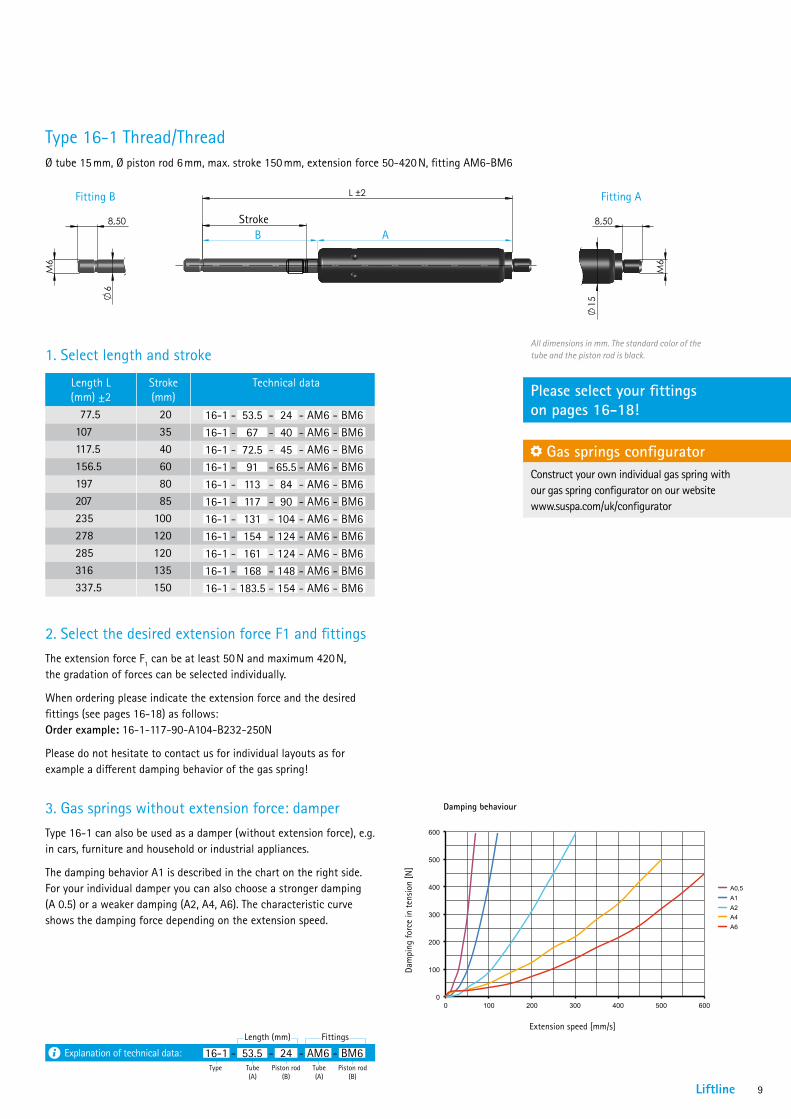
Type 16-1 Thread/ThreadØ tube 15 mm, Ø piston rod 6 mm, max. stroke 150 mm, extension force 50-420 N, fitting AM6-BM6
1. Select length and stroke
Length L (mm) ±2
Stroke (mm)
Technical data
77.5 20 16-1 - 53.5 - 24 - AM6 - BM6107 35 16-1 - 67 - 40 - AM6 - BM6117.5 40 16-1 - 72.5 - 45 - AM6 - BM6156.5 60 16-1 - 91 - 65.5 - AM6 - BM6197 80 16-1 - 113 - 84 - AM6 - BM6207 85 16-1 - 117 - 90 - AM6 - BM6235 100 16-1 - 131 - 104 - AM6 - BM6278 120 16-1 - 154 - 124 - AM6 - BM6285 120 16-1 - 161 - 124 - AM6 - BM6316 135 16-1 - 168 - 148 - AM6 - BM6337.5 150 16-1 - 183.5 - 154 - AM6 - BM6
2. Select the desired extension force F1 and fittingsThe extension force F1 can be at least 50 N and maximum 420 N, the gradation of forces can be selected individually.
When ordering please indicate the extension force and the desired fittings (see pages 16-18) as follows: Order example: 16-1-117-90-A104-B232-250N
Please do not hesitate to contact us for individual layouts as for example a different damping behavior of the gas spring!
Please select your fittings on pages 16-18!
All dimensions in mm. The standard color of the tube and the piston rod is black.
Fitting B Fitting A
Gas springs configuratorConstruct your own individual gas spring with our gas spring configurator on our website www.suspa.com/uk/configurator
Explanation of technical data:Type Tube
(A)Tube (A)
Piston rod (B)
Piston rod (B)
16-1 - 53.5 - 24 - AM6 - BM6Length (mm) Fittings
gem./acc. to VA 04 03 = Kontrollmaß / inspection dimension( ) = Hilfsmaß / reference dimension [ ] = Vorbearbeitungsmaß / pre-work dim.
L ±2
Hub
6
8,50 8,50
15
M6
M6
DIN
ISO 13
715,
Auße
nkan
ten/
outsid
e edg
es
,
Inne
nkan
ten/
inside
edge
s
gepu
tzt/c
leane
dDIN
ISO
1302
Werk
stück
kante
n, we
nn ni
cht a
nders
ang
egeb
en/e
dge o
f wor
kpiec
e unle
ss ot
herw
ise in
didat
ed
uv Rz
100
Rz 2
5
wx Rz
6,3
Rz 1
y
-0,2
+0,2
01.01.2012
Änderungen nur in/revisions with CAD - 3D only
Werkstoff2
Check
Drawn ABC
Date
ISO 128-30Wenn nicht anders angegeben/unless otherwise specified
1:1Maßstab/scale
A3
Maßangabe in Millimeter/dimensions shown in millimetersAllgemeintoleranz/general tolerancesDIN ISO 2768-m
Format/paper-size
Bezeichnung2
neue Zeichnung
16-1_M6_Var2
16-1_M6
Werkstoff
Ausgabe, Datum, Verteiler/edition, date, copies for
Zeichnungsnummer/drawing number
Bezeichnung/nameName
Material
Ersatz für/replacement for
Ersetzt durch/replaced by
Index DateÄnderungs Nr./ECN
alte Zeichnung
Only
thos
e sta
ndar
ds a
nd th
eir re
vision
swh
ich w
here
valid
bef
ore
the
time
ofdr
awing
relea
se a
pply.
Es g
ilt je
wei
ls de
r Sta
nd d
eran
gege
bene
n No
rm zu
mZe
itpun
kt d
er Ze
ichn
ungs
erste
llung
All rig
hts a
re re
serve
d in
acco
rdan
ce w
ith IS
O 16
016.
Copy
ing a
nd us
e of th
is doc
umen
t only
with
aut
horiza
tion.
Non-
comp
lianc
e will r
esult
in Su
spa
seek
ing d
amag
es to
cove
r losse
s.
Alle
Rech
te vo
rbeh
alte
n ge
mäß
DIN
ISO
1601
6.Ve
rwen
dung
und
Ver
vielfä
ltigun
g nu
r bei
schr
iftlich
er Zu
stim
mun
g.Zu
wide
rhan
dlun
gen
verp
flicht
en zu
m Sc
hade
nser
satz.
Blatt/sheet
1/1
StrokeB A
3. Gas springs without extension force: damper Type 16-1 can also be used as a damper (without extension force), e.g. in cars, furniture and household or industrial appliances.
The damping behavior A1 is described in the chart on the right side. For your individual damper you can also choose a stronger damping (A 0.5) or a weaker damping (A2, A4, A6). The characteristic curve shows the damping force depending on the extension speed.
Damping behaviour
Extension speed [mm/s]
Dam
ping
forc
e in
tens
ion
[N]
0
100
200
300
400
500
600
0 100 200 300 400 500 600
A0,5 A1 A2A4 A6

10
gem./acc. to VA 04 03 = Kontrollmaß / inspection dimension( ) = Hilfsmaß / reference dimension [ ] = Vorbearbeitungsmaß / pre-work dim.
15
R7,50
Hub
L 2
15
R7,50
18,5
0
8
8,10 0+0,30
5
8,10 + 0,300
5
DIN
ISO 13
715,
Auße
nkan
ten/
outsid
e edg
es
,
Inne
nkan
ten/
inside
edge
s
gepu
tzt/c
leane
dDIN
ISO
1302
Werk
stück
kante
n, we
nn ni
cht a
nders
ang
egeb
en/e
dge o
f wor
kpiec
e unle
ss ot
herw
ise in
didat
ed
uv Rz
100
Rz 2
5
wx Rz
6,3
Rz 1
y
-0,2
+0,2
01.01.2012
Änderungen nur in/revisions with CAD - 3D only
Werkstoff2
Check
Drawn ABC
Date
ISO 128-30Wenn nicht anders angegeben/unless otherwise specified
1:1Maßstab/scale
A3
Maßangabe in Millimeter/dimensions shown in millimetersAllgemeintoleranz/general tolerancesDIN ISO 2768-m
Format/paper-size
Bezeichnung2
neue Zeichnung
16-2_Augen_geschw
16-2 Auge/Auge geschweißt
Werkstoff
Ausgabe, Datum, Verteiler/edition, date, copies for
Zeichnungsnummer/drawing number
Bezeichnung/nameName
Material
Ersatz für/replacement for
Ersetzt durch/replaced by
Index DateÄnderungs Nr./ECN
alte Zeichnung
Only
thos
e sta
ndar
ds a
nd th
eir re
vision
swh
ich w
here
valid
bef
ore
the
time
ofdr
awing
relea
se a
pply.
Es g
ilt je
wei
ls de
r Sta
nd d
eran
gege
bene
n No
rm zu
mZe
itpun
kt d
er Ze
ichn
ungs
erste
llung
All rig
hts a
re re
serve
d in
acco
rdan
ce w
ith IS
O 16
016.
Copy
ing a
nd us
e of th
is doc
umen
t only
with
aut
horiza
tion.
Non-
comp
lianc
e will r
esult
in Su
spa
seek
ing d
amag
es to
cove
r losse
s.
Alle
Rech
te vo
rbeh
alte
n ge
mäß
DIN
ISO
1601
6.Ve
rwen
dung
und
Ver
vielfä
ltigun
g nu
r bei
schr
iftlich
er Zu
stim
mun
g.Zu
wide
rhan
dlun
gen
verp
flicht
en zu
m Sc
hade
nser
satz.
Blatt/sheet
1/1
Standard program Liftline gas springs type 16-2
Type 16-2 Clevis/Clevis, weldedØ tube 18,5 mm, Ø piston rod 8 mm, max. stroke 250 mm, extension force 80-750 N, fitting A107-B23
Type 16-2 Ball joint/Ball jointØ tube 18,5 mm, Ø piston rod 8 mm, max. stroke 250 mm, extension force 80-750 N, fitting A246-B246
Length L (mm) ±2
Stroke (mm)
Technical data Ordering number
206.5 60 16-2 - 108 - 65 - A107 - B23 01625024246.5 80 16-2 - 128 - 85 - A107 - B23 01625025
256.5 90 16-2 - 128 - 95 - A107 - B23 01625082286.5 100 16-2 - 143 - 110 - A107 - B23 01625026316.5 120 16-2 - 158 - 125 - A107 - B23 01625083326.5 120 16-2 - 168 - 125 - A107 - B23 01625027354.5 133 16-2 - 183 - 138 - A107 - B23 01625084364.5 140 16-2 - 186 - 145 - A107 - B23 01625028407.5 160 16-2 - 201 - 173 - A107 - B23 01625029444.0 178 16-2 - 229.5 - 181 - A107 - B23 01625030485.5 200 16-2 - 240 - 212 - A107 - B23 01625031525.5 220 16-2 - 267 - 225 - A107 - B23 01625032586.5 250 16-2 - 291 - 262 - A107 - B23 01625033
All dimensions in mm. The standard color of the tube and the piston rod is black.
Fitting B
Fitting B
Fitting A
Fitting A
Length L (mm) ±2
Stroke (mm)
Technical data Ordering number
166 40 16-2 - 78 - 50 - A246 - B246 01625078206 57 16-2 - 109 - 59 - A246 - B246 01625014244 80 16-2 - 121 - 85 - A246 - B246 01625015256 85 16-2 - 128 - 90 - A246 - B246 01625079286 100 16-2 - 138 - 110 - A246 - B246 01625016306 105 16-2 - 158 - 110 - A246 - B246 01625080326 120 16-2 - 163 - 125 - A246 - B246 01625017366 140 16-2 - 178 - 150 - A246 - B246 01625018405 160 16-2 - 203 - 164 - A246 - B246 01625019446 180 16-2 - 223 - 185 - A246 - B246 01625020491 195 16-2 - 253 - 200 - A246 - B246 01625081485.5 200 16-2 - 240 - 207.5 - A246 - B246 01625021527 220 16-2 - 264 - 225 - A246 - B246 01625022585.5 250 16-2 - 294 - 253.5 - A246 - B246 01625023
gem./acc. to VA 04 03 = Kontrollmaß / inspection dimension( ) = Hilfsmaß / reference dimension [ ] = Vorbearbeitungsmaß / pre-work dim.
Hub
L 2
16,5
0
8
18
10
25
1312
SW13
M8
DIN
ISO 13
715,
Auße
nkan
ten/
outsid
e edg
es
,
Inne
nkan
ten/
inside
edge
s
gepu
tzt/c
leane
dDIN
ISO
1302
Werk
stück
kante
n, we
nn ni
cht a
nders
ang
egeb
en/e
dge o
f wor
kpiec
e unle
ss ot
herw
ise in
didat
ed
uv Rz
100
Rz 2
5
wx Rz
6,3
Rz 1
y
-0,2
+0,2
27.03.2013
Änderungen nur in/revisions with CAD - 3D only Check
Drawn RMA
Date
ISO 128-30Wenn nicht anders angegeben/unless otherwise specified
1:1Maßstab/scale
A3
Maßangabe in Millimeter/dimensions shown in millimetersAllgemeintoleranz/general tolerancesDIN ISO 2768-m
Format/paper-size 16-2_Kugelgelenk
16-2 KugelgelenkAusgabe, Datum, Verteiler/edition, date, copies for
Zeichnungsnummer/drawing number
Bezeichnung/nameName
Material
Ersatz für/replacement for
Ersetzt durch/replaced by
Index DateÄnderungs Nr./ECN
Only
thos
e sta
ndar
ds a
nd th
eir re
vision
swh
ich w
here
valid
bef
ore
the
time
ofdr
awing
relea
se a
pply.
Es g
ilt je
wei
ls de
r Sta
nd d
eran
gege
bene
n No
rm zu
mZe
itpun
kt d
er Ze
ichn
ungs
erste
llung
All rig
hts a
re re
serve
d in
acco
rdan
ce w
ith IS
O 16
016.
Copy
ing a
nd us
e of th
is doc
umen
t only
with
aut
horiza
tion.
Non-
comp
lianc
e will r
esult
in Su
spa
seek
ing d
amag
es to
cove
r losse
s.
Alle
Rech
te vo
rbeh
alte
n ge
mäß
DIN
ISO
1601
6.Ve
rwen
dung
und
Ver
vielfä
ltigun
g nu
r bei
schr
iftlich
er Zu
stim
mun
g.Zu
wide
rhan
dlun
gen
verp
flicht
en zu
m Sc
hade
nser
satz.
Blatt/sheet
1/1
Stroke
Stroke
Fitting B Fitting A
B A
Fitting B Fitting A
B A
Liftline 11
gem./acc. to VA 04 03 = Kontrollmaß / inspection dimension( ) = Hilfsmaß / reference dimension [ ] = Vorbearbeitungsmaß / pre-work dim.
L 2
Hub
8
18,5
0
M6
8,50 8,50
M6
DIN
ISO 13
715,
Auße
nkan
ten/
outsid
e edg
es
,
Inne
nkan
ten/
inside
edge
s
gepu
tzt/c
leane
dDIN
ISO
1302
Werk
stück
kante
n, we
nn ni
cht a
nders
ang
egeb
en/e
dge o
f wor
kpiec
e unle
ss ot
herw
ise in
didat
ed
uv Rz
100
Rz 2
5
wx Rz
6,3
Rz 1
y
-0,2
+0,2
01.01.2012
Änderungen nur in/revisions with CAD - 3D only
Werkstoff2
Check
Drawn ABC
Date
ISO 128-30Wenn nicht anders angegeben/unless otherwise specified
1:1Maßstab/scale
A3
Maßangabe in Millimeter/dimensions shown in millimetersAllgemeintoleranz/general tolerancesDIN ISO 2768-m
Format/paper-size
Bezeichnung2
neue Zeichnung
16-2_M6
16-2_M6
Werkstoff
Ausgabe, Datum, Verteiler/edition, date, copies for
Zeichnungsnummer/drawing number
Bezeichnung/nameName
Material
Ersatz für/replacement for
Ersetzt durch/replaced by
Index DateÄnderungs Nr./ECN
alte Zeichnung
Only
thos
e sta
ndar
ds a
nd th
eir re
vision
swh
ich w
here
valid
bef
ore
the
time
ofdr
awing
relea
se a
pply.
Es g
ilt je
wei
ls de
r Sta
nd d
eran
gege
bene
n No
rm zu
mZe
itpun
kt d
er Ze
ichn
ungs
erste
llung
All rig
hts a
re re
serve
d in
acco
rdan
ce w
ith IS
O 16
016.
Copy
ing a
nd us
e of th
is doc
umen
t only
with
aut
horiza
tion.
Non-
comp
lianc
e will r
esult
in Su
spa
seek
ing d
amag
es to
cove
r losse
s.
Alle
Rech
te vo
rbeh
alte
n ge
mäß
DIN
ISO
1601
6.Ve
rwen
dung
und
Ver
vielfä
ltigun
g nu
r bei
schr
iftlich
er Zu
stim
mun
g.Zu
wide
rhan
dlun
gen
verp
flicht
en zu
m Sc
hade
nser
satz.
Blatt/sheet
1/1
1. Select length and stroke
Length L (mm) ±2
Stroke (mm)
Technical data
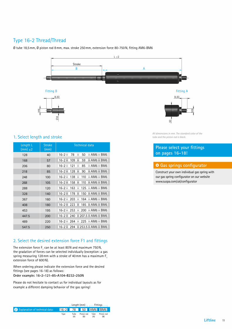
128 40 16-2 - 78 - 50 - AM6 - BM6
168 57 16-2 - 109 - 59 - AM6 - BM6
206 80 16-2 - 121 - 85 - AM6 - BM6
218 85 16-2 - 128 - 90 - AM6 - BM6
248 100 16-2 - 138 - 110 - AM6 - BM6
268 105 16-2 - 158 - 110 - AM6 - BM6
288 120 16-2 - 163 - 125 - AM6 - BM6
328 140 16-2 - 178 - 150 - AM6 - BM6
367 160 16-2 - 203 - 164 - AM6 - BM6
408 180 16-2 - 223 - 185 - AM6 - BM6
453 195 16-2 - 253 - 200 - AM6 - BM6
447.5 200 16-2 - 240 - 207.5 - AM6 - BM6
489 220 16-2 - 264 - 225 - AM6 - BM6
547.5 250 16-2 - 294 - 253.5 - AM6 - BM6
2. Select the desired extension force F1 and fittingsThe extension force F1 can be at least 80 N and maximum 750 N, the gradation of forces can be selected individually (exception: a gas spring measuring 128 mm with a stroke of 40 mm has a maximum F1 extension force of 600 N).
When ordering please indicate the extension force and the desired fittings (see pages 16-18) as follows: Order example: 16-2-121-85-A104-B232-250N
Please do not hesitate to contact us for individual layouts as for example a different damping behavior of the gas spring!
Please select your fittings on pages 16-18!
All dimensions in mm. The standard color of the tube and the piston rod is black.
Fitting B Fitting A
Gas springs configuratorConstruct your own individual gas spring with our gas spring configurator on our website www.suspa.com/uk/configurator
Stroke
Type 16-2 Thread/ThreadØ tube 18,5 mm, Ø piston rod 8 mm, max. stroke 250 mm, extension force 80-750 N, fitting AM6-BM6
gem./acc. to VA 04 03 = Kontrollmaß / inspection dimension( ) = Hilfsmaß / reference dimension [ ] = Vorbearbeitungsmaß / pre-work dim.
L 2
Hub 8
18,5
0
M6
8,50 8,50
M6
DIN
ISO 13
715,
Auße
nkan
ten/
outsid
e edg
es
,
Inne
nkan
ten/
inside
edge
s
gepu
tzt/c
leane
dDIN
ISO
1302
Werk
stück
kante
n, we
nn ni
cht a
nders
ang
egeb
en/e
dge o
f wor
kpiec
e unle
ss ot
herw
ise in
didat
ed
uv Rz
100
Rz 2
5
wx Rz
6,3
Rz 1
y
-0,2
+0,2
01.01.2012
Änderungen nur in/revisions with CAD - 3D only
Werkstoff2
Check
Drawn ABC
Date
ISO 128-30Wenn nicht anders angegeben/unless otherwise specified
1:1Maßstab/scale
A3
Maßangabe in Millimeter/dimensions shown in millimetersAllgemeintoleranz/general tolerancesDIN ISO 2768-m
Format/paper-size
Bezeichnung2
neue Zeichnung
16-2_M6
16-2_M6
Werkstoff
Ausgabe, Datum, Verteiler/edition, date, copies for
Zeichnungsnummer/drawing number
Bezeichnung/nameName
Material
Ersatz für/replacement for
Ersetzt durch/replaced by
Index DateÄnderungs Nr./ECN
alte Zeichnung
Only
thos
e sta
ndar
ds a
nd th
eir re
vision
swh
ich w
here
valid
bef
ore
the
time
ofdr
awing
relea
se a
pply.
Es g
ilt je
wei
ls de
r Sta
nd d
eran
gege
bene
n No
rm zu
mZe
itpun
kt d
er Ze
ichn
ungs
erste
llung
All rig
hts a
re re
serve
d in
acco
rdan
ce w
ith IS
O 16
016.
Copy
ing a
nd us
e of th
is doc
umen
t only
with
aut
horiza
tion.
Non-
comp
lianc
e will r
esult
in Su
spa
seek
ing d
amag
es to
cove
r losse
s.
Alle
Rech
te vo
rbeh
alte
n ge
mäß
DIN
ISO
1601
6.Ve
rwen
dung
und
Ver
vielfä
ltigun
g nu
r bei
schr
iftlich
er Zu
stim
mun
g.Zu
wide
rhan
dlun
gen
verp
flicht
en zu
m Sc
hade
nser
satz.
Blatt/sheet
1/1
B A
Explanation of technical data:Type Tube
(A)Tube (A)
Piston rod (B)
Piston rod (B)
16-2 - 78 - 50 - AM6 - BM6Length (mm) Fittings

12
gem./acc. to VA 04 03 = Kontrollmaß / inspection dimension( ) = Hilfsmaß / reference dimension [ ] = Vorbearbeitungsmaß / pre-work dim.
Hub
L 2
2210
15
10
1213
25
M8
SW13
DIN
ISO 13
715,
Auße
nkan
ten/
outsid
e edg
es
,
Inne
nkan
ten/
inside
edge
s
gepu
tzt/c
leane
dDIN
ISO
1302
Werk
stück
kante
n, we
nn ni
cht a
nders
ang
egeb
en/e
dge o
f wor
kpiec
e unle
ss ot
herw
ise in
didat
ed
uv Rz
100
Rz 2
5
wx Rz
6,3
Rz 1
y
-0,2
+0,2
27.03.2013
Änderungen nur in/revisions with CAD - 3D only Check
Drawn RMA
Date
ISO 128-30Wenn nicht anders angegeben/unless otherwise specified
1:1Maßstab/scale
A3
Maßangabe in Millimeter/dimensions shown in millimetersAllgemeintoleranz/general tolerancesDIN ISO 2768-m
Format/paper-size 16-4_Kugelgelenk
16-4_KugelgelenkAusgabe, Datum, Verteiler/edition, date, copies for
Zeichnungsnummer/drawing number
Bezeichnung/nameName
Material
Ersatz für/replacement for
Ersetzt durch/replaced by
Index DateÄnderungs Nr./ECN
Only
thos
e sta
ndar
ds a
nd th
eir re
vision
swh
ich w
here
valid
bef
ore
the
time
ofdr
awing
relea
se a
pply.
Es g
ilt je
wei
ls de
r Sta
nd d
eran
gege
bene
n No
rm zu
mZe
itpun
kt d
er Ze
ichn
ungs
erste
llung
All rig
hts a
re re
serve
d in
acco
rdan
ce w
ith IS
O 16
016.
Copy
ing a
nd us
e of th
is doc
umen
t only
with
aut
horiza
tion.
Non-
comp
lianc
e will r
esult
in Su
spa
seek
ing d
amag
es to
cove
r losse
s.
Alle
Rech
te vo
rbeh
alte
n ge
mäß
DIN
ISO
1601
6.Ve
rwen
dung
und
Ver
vielfä
ltigun
g nu
r bei
schr
iftlich
er Zu
stim
mun
g.Zu
wide
rhan
dlun
gen
verp
flicht
en zu
m Sc
hade
nser
satz.
Blatt/sheet
1/1
Type 16-4 Clevis/Clevis, weldedØ tube 22 mm, Ø piston rod 10 mm, max. stroke 495 mm, extension force 100-1,200 N, fitting A23-B23
Type 16-4 Ball joint/Ball jointØ tube 22 mm, Ø piston rod 10 mm, max. stroke 495 mm, extension force 100-1,200 N, fitting A207-B207
gem./acc. to VA 04 03 = Kontrollmaß / inspection dimension( ) = Hilfsmaß / reference dimension [ ] = Vorbearbeitungsmaß / pre-work dim.
15
R7,50
Hub
L 2
15
R7,50
10
22
8,10 0+0,30
5
8,10 0+0,30
5
DIN
ISO 13
715,
Auße
nkan
ten/
outsid
e edg
es
,
Inne
nkan
ten/
inside
edge
s
gepu
tzt/c
leane
dDIN
ISO
1302
Werk
stück
kante
n, we
nn ni
cht a
nders
ang
egeb
en/e
dge o
f wor
kpiec
e unle
ss ot
herw
ise in
didat
ed
uv Rz
100
Rz 2
5
wx Rz
6,3
Rz 1
y
-0,2
+0,2
12.02.2013
Änderungen nur in/revisions with CAD - 3D only Check
Drawn RMA
Date
ISO 128-30Wenn nicht anders angegeben/unless otherwise specified
1:1Maßstab/scale
A3
Maßangabe in Millimeter/dimensions shown in millimetersAllgemeintoleranz/general tolerancesDIN ISO 2768-m
Format/paper-size 16-4_Augen_geschw
16-4 Augen geschweißtAusgabe, Datum, Verteiler/edition, date, copies for
Zeichnungsnummer/drawing number
Bezeichnung/nameName
Material
Ersatz für/replacement for
Ersetzt durch/replaced by
Index DateÄnderungs Nr./ECN
Only
thos
e sta
ndar
ds a
nd th
eir re
vision
swh
ich w
here
valid
bef
ore
the
time
ofdr
awing
relea
se a
pply.
Es g
ilt je
wei
ls de
r Sta
nd d
eran
gege
bene
n No
rm zu
mZe
itpun
kt d
er Ze
ichn
ungs
erste
llung
All rig
hts a
re re
serve
d in
acco
rdan
ce w
ith IS
O 16
016.
Copy
ing a
nd us
e of th
is doc
umen
t only
with
aut
horiza
tion.
Non-
comp
lianc
e will r
esult
in Su
spa
seek
ing d
amag
es to
cove
r losse
s.
Alle
Rech
te vo
rbeh
alte
n ge
mäß
DIN
ISO
1601
6.Ve
rwen
dung
und
Ver
vielfä
ltigun
g nu
r bei
schr
iftlich
er Zu
stim
mun
g.Zu
wide
rhan
dlun
gen
verp
flicht
en zu
m Sc
hade
nser
satz.
Blatt/sheet
1/1 gem./acc. to VA 04 03 = Kontrollmaß / inspection dimension( ) = Hilfsmaß / reference dimension [ ] = Vorbearbeitungsmaß / pre-work dim.
15
R7,50
Hub
L 2
15
R7,50
10
22
8,10 0+0,30
5
8,10 0+0,30
5
DIN
ISO 13
715,
Auße
nkan
ten/
outsid
e edg
es
,
Inne
nkan
ten/
inside
edge
s
gepu
tzt/c
leane
dDIN
ISO
1302
Werk
stück
kante
n, we
nn ni
cht a
nders
ang
egeb
en/e
dge o
f wor
kpiec
e unle
ss ot
herw
ise in
didat
ed
uv Rz
100
Rz 2
5
wx Rz
6,3
Rz 1
y
-0,2
+0,2
12.02.2013
Änderungen nur in/revisions with CAD - 3D only Check
Drawn RMA
Date
ISO 128-30Wenn nicht anders angegeben/unless otherwise specified
1:1Maßstab/scale
A3
Maßangabe in Millimeter/dimensions shown in millimetersAllgemeintoleranz/general tolerancesDIN ISO 2768-m
Format/paper-size 16-4_Augen_geschw
16-4 Augen geschweißtAusgabe, Datum, Verteiler/edition, date, copies for
Zeichnungsnummer/drawing number
Bezeichnung/nameName
Material
Ersatz für/replacement for
Ersetzt durch/replaced by
Index DateÄnderungs Nr./ECN
Only
thos
e sta
ndar
ds a
nd th
eir re
vision
swh
ich w
here
valid
bef
ore
the
time
ofdr
awing
relea
se a
pply.
Es g
ilt je
wei
ls de
r Sta
nd d
eran
gege
bene
n No
rm zu
mZe
itpun
kt d
er Ze
ichn
ungs
erste
llung
All rig
hts a
re re
serve
d in
acco
rdan
ce w
ith IS
O 16
016.
Copy
ing a
nd us
e of th
is doc
umen
t only
with
aut
horiza
tion.
Non-
comp
lianc
e will r
esult
in Su
spa
seek
ing d
amag
es to
cove
r losse
s.
Alle
Rech
te vo
rbeh
alte
n ge
mäß
DIN
ISO
1601
6.Ve
rwen
dung
und
Ver
vielfä
ltigun
g nu
r bei
schr
iftlich
er Zu
stim
mun
g.Zu
wide
rhan
dlun
gen
verp
flicht
en zu
m Sc
hade
nser
satz.
Blatt/sheet
1/1
gem./acc. to VA 04 03 = Kontrollmaß / inspection dimension( ) = Hilfsmaß / reference dimension [ ] = Vorbearbeitungsmaß / pre-work dim.
15
R7,50
Hub
L 2
15
R7,50
10
22
8,10 0+0,30
5
8,10 0+0,30
5
DIN
ISO 13
715,
Auße
nkan
ten/
outsid
e edg
es
,
Inne
nkan
ten/
inside
edge
s
gepu
tzt/c
leane
dDIN
ISO
1302
Werk
stück
kante
n, we
nn ni
cht a
nders
ang
egeb
en/e
dge o
f wor
kpiec
e unle
ss ot
herw
ise in
didat
ed
uv Rz
100
Rz 2
5
wx Rz
6,3
Rz 1
y
-0,2
+0,2
12.02.2013
Änderungen nur in/revisions with CAD - 3D only Check
Drawn RMA
Date
ISO 128-30Wenn nicht anders angegeben/unless otherwise specified
1:1Maßstab/scale
A3
Maßangabe in Millimeter/dimensions shown in millimetersAllgemeintoleranz/general tolerancesDIN ISO 2768-m
Format/paper-size 16-4_Augen_geschw
16-4 Augen geschweißtAusgabe, Datum, Verteiler/edition, date, copies for
Zeichnungsnummer/drawing number
Bezeichnung/nameName
Material
Ersatz für/replacement for
Ersetzt durch/replaced by
Index DateÄnderungs Nr./ECN
Only
thos
e sta
ndar
ds a
nd th
eir re
vision
swh
ich w
here
valid
bef
ore
the
time
ofdr
awing
relea
se a
pply.
Es g
ilt je
wei
ls de
r Sta
nd d
eran
gege
bene
n No
rm zu
mZe
itpun
kt d
er Ze
ichn
ungs
erste
llung
All rig
hts a
re re
serve
d in
acco
rdan
ce w
ith IS
O 16
016.
Copy
ing a
nd us
e of th
is doc
umen
t only
with
aut
horiza
tion.
Non-
comp
lianc
e will r
esult
in Su
spa
seek
ing d
amag
es to
cove
r losse
s.
Alle
Rech
te vo
rbeh
alte
n ge
mäß
DIN
ISO
1601
6.Ve
rwen
dung
und
Ver
vielfä
ltigun
g nu
r bei
schr
iftlich
er Zu
stim
mun
g.Zu
wide
rhan
dlun
gen
verp
flicht
en zu
m Sc
hade
nser
satz.
Blatt/sheet
1/1
Stroke
gem./acc. to VA 04 03 = Kontrollmaß / inspection dimension( ) = Hilfsmaß / reference dimension [ ] = Vorbearbeitungsmaß / pre-work dim.
Hub
L 2
2210
15
10
1213
25
M8
SW13
DIN
ISO 13
715,
Auße
nkan
ten/
outsid
e edg
es
,
Inne
nkan
ten/
inside
edge
s
gepu
tzt/c
leane
dDIN
ISO
1302
Werk
stück
kante
n, we
nn ni
cht a
nders
ang
egeb
en/e
dge o
f wor
kpiec
e unle
ss ot
herw
ise in
didat
ed
uv Rz
100
Rz 2
5
wx Rz
6,3
Rz 1
y
-0,2
+0,2
27.03.2013
Änderungen nur in/revisions with CAD - 3D only Check
Drawn RMA
Date
ISO 128-30Wenn nicht anders angegeben/unless otherwise specified
1:1Maßstab/scale
A3
Maßangabe in Millimeter/dimensions shown in millimetersAllgemeintoleranz/general tolerancesDIN ISO 2768-m
Format/paper-size 16-4_Kugelgelenk
16-4_KugelgelenkAusgabe, Datum, Verteiler/edition, date, copies for
Zeichnungsnummer/drawing number
Bezeichnung/nameName
Material
Ersatz für/replacement for
Ersetzt durch/replaced by
Index DateÄnderungs Nr./ECN
Only
thos
e sta
ndar
ds a
nd th
eir re
vision
swh
ich w
here
valid
bef
ore
the
time
ofdr
awing
relea
se a
pply.
Es g
ilt je
wei
ls de
r Sta
nd d
eran
gege
bene
n No
rm zu
mZe
itpun
kt d
er Ze
ichn
ungs
erste
llung
All rig
hts a
re re
serve
d in
acco
rdan
ce w
ith IS
O 16
016.
Copy
ing a
nd us
e of th
is doc
umen
t only
with
aut
horiza
tion.
Non-
comp
lianc
e will r
esult
in Su
spa
seek
ing d
amag
es to
cove
r losse
s.
Alle
Rech
te vo
rbeh
alte
n ge
mäß
DIN
ISO
1601
6.Ve
rwen
dung
und
Ver
vielfä
ltigun
g nu
r bei
schr
iftlich
er Zu
stim
mun
g.Zu
wide
rhan
dlun
gen
verp
flicht
en zu
m Sc
hade
nser
satz.
Blatt/sheet
1/1
gem./acc. to VA 04 03 = Kontrollmaß / inspection dimension( ) = Hilfsmaß / reference dimension [ ] = Vorbearbeitungsmaß / pre-work dim.
Hub
L 2
2210
15
1012
13
25
M8
SW13
DIN
ISO 13
715,
Auße
nkan
ten/
outsid
e edg
es
,
Inne
nkan
ten/
inside
edge
s
gepu
tzt/c
leane
dDIN
ISO
1302
Werk
stück
kante
n, we
nn ni
cht a
nders
ang
egeb
en/e
dge o
f wor
kpiec
e unle
ss ot
herw
ise in
didat
ed
uv Rz
100
Rz 2
5
wx Rz
6,3
Rz 1
y
-0,2
+0,2
27.03.2013
Änderungen nur in/revisions with CAD - 3D only Check
Drawn RMA
Date
ISO 128-30Wenn nicht anders angegeben/unless otherwise specified
1:1Maßstab/scale
A3
Maßangabe in Millimeter/dimensions shown in millimetersAllgemeintoleranz/general tolerancesDIN ISO 2768-m
Format/paper-size 16-4_Kugelgelenk
16-4_KugelgelenkAusgabe, Datum, Verteiler/edition, date, copies for
Zeichnungsnummer/drawing number
Bezeichnung/nameName
Material
Ersatz für/replacement for
Ersetzt durch/replaced by
Index DateÄnderungs Nr./ECN
Only
thos
e sta
ndar
ds a
nd th
eir re
vision
swh
ich w
here
valid
bef
ore
the
time
ofdr
awing
relea
se a
pply.
Es g
ilt je
wei
ls de
r Sta
nd d
eran
gege
bene
n No
rm zu
mZe
itpun
kt d
er Ze
ichn
ungs
erste
llung
All rig
hts a
re re
serve
d in
acco
rdan
ce w
ith IS
O 16
016.
Copy
ing a
nd us
e of th
is doc
umen
t only
with
aut
horiza
tion.
Non-
comp
lianc
e will r
esult
in Su
spa
seek
ing d
amag
es to
cove
r losse
s.
Alle
Rech
te vo
rbeh
alte
n ge
mäß
DIN
ISO
1601
6.Ve
rwen
dung
und
Ver
vielfä
ltigun
g nu
r bei
schr
iftlich
er Zu
stim
mun
g.Zu
wide
rhan
dlun
gen
verp
flicht
en zu
m Sc
hade
nser
satz.
Blatt/sheet
1/1
gem./acc. to VA 04 03 = Kontrollmaß / inspection dimension( ) = Hilfsmaß / reference dimension [ ] = Vorbearbeitungsmaß / pre-work dim.
Hub
L 2
2210
15
10
1213
25
M8
SW13
DIN
ISO 13
715,
Auße
nkan
ten/
outsid
e edg
es
,
Inne
nkan
ten/
inside
edge
s
gepu
tzt/c
leane
dDIN
ISO
1302
Werk
stück
kante
n, we
nn ni
cht a
nders
ang
egeb
en/e
dge o
f wor
kpiec
e unle
ss ot
herw
ise in
didat
ed
uv Rz
100
Rz 2
5
wx Rz
6,3
Rz 1
y
-0,2
+0,2
27.03.2013
Änderungen nur in/revisions with CAD - 3D only Check
Drawn RMA
Date
ISO 128-30Wenn nicht anders angegeben/unless otherwise specified
1:1Maßstab/scale
A3
Maßangabe in Millimeter/dimensions shown in millimetersAllgemeintoleranz/general tolerancesDIN ISO 2768-m
Format/paper-size 16-4_Kugelgelenk
16-4_KugelgelenkAusgabe, Datum, Verteiler/edition, date, copies for
Zeichnungsnummer/drawing number
Bezeichnung/nameName
Material
Ersatz für/replacement for
Ersetzt durch/replaced by
Index DateÄnderungs Nr./ECN
Only
thos
e sta
ndar
ds a
nd th
eir re
vision
swh
ich w
here
valid
bef
ore
the
time
ofdr
awing
relea
se a
pply.
Es g
ilt je
wei
ls de
r Sta
nd d
eran
gege
bene
n No
rm zu
mZe
itpun
kt d
er Ze
ichn
ungs
erste
llung
All rig
hts a
re re
serve
d in
acco
rdan
ce w
ith IS
O 16
016.
Copy
ing a
nd us
e of th
is doc
umen
t only
with
aut
horiza
tion.
Non-
comp
lianc
e will r
esult
in Su
spa
seek
ing d
amag
es to
cove
r losse
s.
Alle
Rech
te vo
rbeh
alte
n ge
mäß
DIN
ISO
1601
6.Ve
rwen
dung
und
Ver
vielfä
ltigun
g nu
r bei
schr
iftlich
er Zu
stim
mun
g.Zu
wide
rhan
dlun
gen
verp
flicht
en zu
m Sc
hade
nser
satz.
Blatt/sheet
1/1
Stroke
Standard program Liftline gas springs type 16-4
All dimensions in mm. The standard color of the tube and the piston rod is black.
Length L (mm) ±2
Stroke (mm)
Technical data Ordering number
283 95 16-4 - 153 - 100 - A23 - B23 01625043383 145 16-4 - 203 - 150 - A23 - B23 01625044
483 195 16-4 - 253 - 200 - A23 - B23 01625045586 245 16-4 - 294 - 262 - A23 - B23 01625046683 295 16-4 - 353 - 300 - A23 - B23 01625047783 345 16-4 - 403 - 350 - A23 - B23 01625048883 395 16-4 - 453 - 400 - A23 - B23 01625049983 445 16-4 - 503 - 450 - A23 - B23 01625050
1083 495 16-4 - 553 - 500 - A23 - B23 01625051
Length L (mm) ±2
Stroke (mm)
Technical data Ordering number
286 98 16-4 - 148 - 100 - A207 - B207 01625034326 120 16-4 - 163 - 125 - A207 - B207 01625085386 148 16-4 - 198 - 150 - A207 - B207 01625035405 150 16-4 - 198 - 170 - A207 - B207 01625086444 168 16-4 - 236 - 170 - A207 - B207 01625087486 198 16-4 - 248 - 200 - A207 - B207 01625036586 248 16-4 - 298 - 250 - A207 - B207 01625037686 295 16-4 - 348 - 300 - A207 - B207 01625038786 345 16-4 - 398 - 350 - A207 - B207 01625039806 345 16-4 - 418 - 350 - A207 - B207 01625088886 395 16-4 - 448 - 400 - A207 - B207 01625040986 445 16-4 - 498 - 450 - A207 - B207 01625041
1,086 495 16-4 - 548 - 500 - A207 - B207 01625042
Fitting B
Fitting B
Fitting A
Fitting A
Fitting B Fitting A
Fitting B Fitting A
B A
B A

Liftline 13
Type 16-4 Thread/ThreadØ tube 22 mm, Ø piston rod 10 mm, max. stroke 495 mm, extension force 100-1,200 N, fitting AM8-BM8
gem./acc. to VA 04 03
= Kontrollmaß / inspection dimension
( ) = Hilfsmaß / reference dimension [ ] = Vorbearbeitungsmaß / pre-work dim.
L 2
Hub
22
10
9,50 9,50
M8
M8
DIN
ISO 1
3715
, Auß
enka
nten
/out
side
edge
s
, In
nenk
ante
n/ins
ide
edge
s
gepu
tzt/c
leane
dDI
N ISO
1302
Wer
kstü
ckka
nten
, wen
n nic
ht a
nder
s ang
egeb
en/e
dge
of w
orkp
iece
unle
ss ot
herw
ise in
dida
ted
uv Rz
100
Rz 2
5
wx Rz
6,3
Rz 1
y
-0,2
+0,2
12.02.2013
Änderungen nur in/revisions with CAD - 3D only Check
Drawn RMA
Date
ISO 128-30Wenn nicht anders angegeben/unless otherwise specified
1:1Maßstab/scale
A3
Maßangabe in Millimeter/dimensions shown in millimetersAllgemeintoleranz/general tolerancesDIN ISO 2768-m
Format/paper-size 16-4_M8
16-4_M8
Ausgabe, Datum, Verteiler/edition, date, copies for
Zeichnungsnummer/drawing number
Bezeichnung/nameName
Material
Ersatz für/replacement for
Ersetzt durch/replaced by
Index DateÄnderungs Nr./ECN
Onl
y th
ose
stand
ards
and
thei
r rev
ision
sw
hich
whe
re v
alid
bef
ore
the
time
ofdr
awin
g re
leas
e ap
ply.
Es g
ilt je
wei
ls d
er S
tand
der
ang
egeb
enen
Nor
m z
umZe
itpun
kt d
er Z
eich
nung
sers
tellu
ng
All ri
ghts
are
rese
rved
in a
ccor
danc
e w
ith IS
O 1
6016
.Co
pying
and
use
of t
his d
ocum
ent o
nly w
ith a
utho
rizat
ion.
Non-
com
plia
nce
will
resu
lt in
Susp
a se
eking
dam
ages
to c
over
losse
s.
Alle
Rec
hte
vorb
ehal
ten
gem
äß D
IN IS
O 1
6016
.Ve
rwen
dung
und
Ver
vielfä
ltigun
g nu
r bei
schr
iftlic
her Z
ustim
mun
g.Zu
wid
erha
ndlu
ngen
ver
pflic
hten
zum
Sch
aden
sersa
tz.
Blatt/sheet
1/1
Stroke
Fitting B Fitting A
1. Select length and stroke
Length L (mm) ±2
Stroke (mm)
Technical data
248 98 16-4 - 148 - 100 - AM8 - BM8
288 120 16-4 - 163 - 125 - AM8 - BM8
348 148 16-4 - 198 - 150 - AM8 - BM8
367 150 16-4 - 198 - 170 - AM8 - BM8
406 168 16-4 - 236 - 170 - AM8 - BM8
448 198 16-4 - 248 - 200 - AM8 - BM8
548 248 16-4 - 298 - 250 - AM8 - BM8
648 295 16-4 - 348 - 300 - AM8 - BM8
748 345 16-4 - 398 - 350 - AM8 - BM8
768 345 16-4 - 418 - 350 - AM8 - BM8
848 395 16-4 - 448 - 400 - AM8 - BM8
948 445 16-4 - 498 - 450 - AM8 - BM8
1,048 495 16-4 - 548 - 500 - AM8 - BM8
2. Select the desired extension force F1 and fittingsThe extension force F1 can be at least 100 N and maximum 1,200 N, the gradation of forces can be selected individually.
When ordering please indicate the extension force and the desired fittings (see pages 16-18) as follows: Order example: 16-4-163-125-A31-B21-500N
Please do not hesitate to contact us for individual layouts as for example a different damping behavior of the gas spring!
Please select your fittings on pages 16-18!
All dimensions in mm. The standard color of the tube and the piston rod is black.
Gas springs configuratorConstruct your own individual gas spring with our gas spring configurator on our website www.suspa.com/uk/configurator
B A
Explanation of technical data:Type Tube
(A)Tube (A)
Piston rod (B)
Piston rod (B)
16-4 - 148 - 100 - AM8 - BM8Length (mm) Fittings
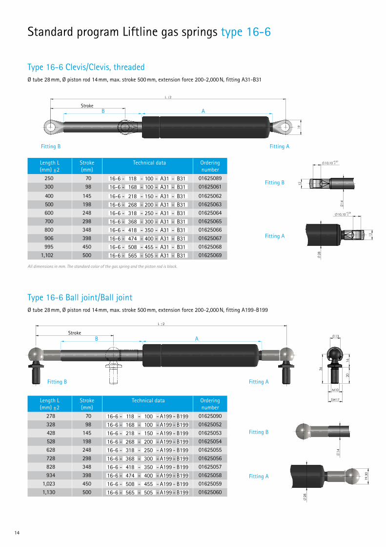
14
Type 16-6 Ball joint/Ball jointØ tube 28 mm, Ø piston rod 14 mm, max. stroke 500 mm, extension force 200-2,000 N, fitting A199-B199
gem./acc. to VA 04 03 = Kontrollmaß / inspection dimension( ) = Hilfsmaß / reference dimension [ ] = Vorbearbeitungsmaß / pre-work dim.
Hub
L 2
14 28
19,3
0
13
36
1620
M10
SW17
DIN
ISO 13
715,
Auße
nkan
ten/
outsid
e edg
es
,
Inne
nkan
ten/
inside
edge
s
gepu
tzt/c
leane
dDIN
ISO
1302
Werk
stück
kante
n, we
nn ni
cht a
nders
ang
egeb
en/e
dge o
f wor
kpiec
e unle
ss ot
herw
ise in
didat
ed
uv Rz
100
Rz 2
5
wx Rz
6,3
Rz 1
y
-0,2
+0,2
27.03.2013
Änderungen nur in/revisions with CAD - 3D only Check
Drawn RMA
Date
ISO 128-30Wenn nicht anders angegeben/unless otherwise specified
1:1Maßstab/scale
A3
Maßangabe in Millimeter/dimensions shown in millimetersAllgemeintoleranz/general tolerancesDIN ISO 2768-m
Format/paper-size 16-6_Kugelgelenk
16-6 KugelgelenkAusgabe, Datum, Verteiler/edition, date, copies for
Zeichnungsnummer/drawing number
Bezeichnung/nameName
Material
Ersatz für/replacement for
Ersetzt durch/replaced by
Index DateÄnderungs Nr./ECN
Only
thos
e sta
ndar
ds a
nd th
eir re
vision
swh
ich w
here
valid
bef
ore
the
time
ofdr
awing
relea
se a
pply.
Es g
ilt je
wei
ls de
r Sta
nd d
eran
gege
bene
n No
rm zu
mZe
itpun
kt d
er Ze
ichn
ungs
erste
llung
All rig
hts a
re re
serve
d in
acco
rdan
ce w
ith IS
O 16
016.
Copy
ing a
nd us
e of th
is doc
umen
t only
with
aut
horiza
tion.
Non-
comp
lianc
e will r
esult
in Su
spa
seek
ing d
amag
es to
cove
r losse
s.
Alle
Rech
te vo
rbeh
alte
n ge
mäß
DIN
ISO
1601
6.Ve
rwen
dung
und
Ver
vielfä
ltigun
g nu
r bei
schr
iftlich
er Zu
stim
mun
g.Zu
wide
rhan
dlun
gen
verp
flicht
en zu
m Sc
hade
nser
satz.
Blatt/sheet
1/1
gem./acc. to VA 04 03 = Kontrollmaß / inspection dimension( ) = Hilfsmaß / reference dimension [ ] = Vorbearbeitungsmaß / pre-work dim.
Hub
L 214 28
19,3
0
13
36
1620
M10
SW17
DIN
ISO 13
715,
Auße
nkan
ten/
outsid
e edg
es
,
Inne
nkan
ten/
inside
edge
s
gepu
tzt/c
leane
dDIN
ISO
1302
Werk
stück
kante
n, we
nn ni
cht a
nders
ang
egeb
en/e
dge o
f wor
kpiec
e unle
ss ot
herw
ise in
didat
ed
uv Rz
100
Rz 2
5
wx Rz
6,3
Rz 1
y
-0,2
+0,2
27.03.2013
Änderungen nur in/revisions with CAD - 3D only Check
Drawn RMA
Date
ISO 128-30Wenn nicht anders angegeben/unless otherwise specified
1:1Maßstab/scale
A3
Maßangabe in Millimeter/dimensions shown in millimetersAllgemeintoleranz/general tolerancesDIN ISO 2768-m
Format/paper-size 16-6_Kugelgelenk
16-6 KugelgelenkAusgabe, Datum, Verteiler/edition, date, copies for
Zeichnungsnummer/drawing number
Bezeichnung/nameName
Material
Ersatz für/replacement for
Ersetzt durch/replaced by
Index DateÄnderungs Nr./ECN
Only
thos
e sta
ndar
ds a
nd th
eir re
vision
swh
ich w
here
valid
bef
ore
the
time
ofdr
awing
relea
se a
pply.
Es g
ilt je
wei
ls de
r Sta
nd d
eran
gege
bene
n No
rm zu
mZe
itpun
kt d
er Ze
ichn
ungs
erste
llung
All rig
hts a
re re
serve
d in
acco
rdan
ce w
ith IS
O 16
016.
Copy
ing a
nd us
e of th
is doc
umen
t only
with
aut
horiza
tion.
Non-
comp
lianc
e will r
esult
in Su
spa
seek
ing d
amag
es to
cove
r losse
s.
Alle
Rech
te vo
rbeh
alte
n ge
mäß
DIN
ISO
1601
6.Ve
rwen
dung
und
Ver
vielfä
ltigun
g nu
r bei
schr
iftlich
er Zu
stim
mun
g.Zu
wide
rhan
dlun
gen
verp
flicht
en zu
m Sc
hade
nser
satz.
Blatt/sheet
1/1
gem./acc. to VA 04 03 = Kontrollmaß / inspection dimension( ) = Hilfsmaß / reference dimension [ ] = Vorbearbeitungsmaß / pre-work dim.
Hub
L 2
14 28
19,3
0
13
36
1620
M10
SW17
DIN
ISO 13
715,
Auße
nkan
ten/
outsid
e edg
es
,
Inne
nkan
ten/
inside
edge
s
gepu
tzt/c
leane
dDIN
ISO
1302
Werk
stück
kante
n, we
nn ni
cht a
nders
ang
egeb
en/e
dge o
f wor
kpiec
e unle
ss ot
herw
ise in
didat
ed
uv Rz
100
Rz 2
5
wx Rz
6,3
Rz 1
y
-0,2
+0,2
27.03.2013
Änderungen nur in/revisions with CAD - 3D only Check
Drawn RMA
Date
ISO 128-30Wenn nicht anders angegeben/unless otherwise specified
1:1Maßstab/scale
A3
Maßangabe in Millimeter/dimensions shown in millimetersAllgemeintoleranz/general tolerancesDIN ISO 2768-m
Format/paper-size 16-6_Kugelgelenk
16-6 KugelgelenkAusgabe, Datum, Verteiler/edition, date, copies for
Zeichnungsnummer/drawing number
Bezeichnung/nameName
Material
Ersatz für/replacement for
Ersetzt durch/replaced by
Index DateÄnderungs Nr./ECN
Only
thos
e sta
ndar
ds a
nd th
eir re
vision
swh
ich w
here
valid
bef
ore
the
time
ofdr
awing
relea
se a
pply.
Es g
ilt je
wei
ls de
r Sta
nd d
eran
gege
bene
n No
rm zu
mZe
itpun
kt d
er Ze
ichn
ungs
erste
llung
All rig
hts a
re re
serve
d in
acco
rdan
ce w
ith IS
O 16
016.
Copy
ing a
nd us
e of th
is doc
umen
t only
with
aut
horiza
tion.
Non-
comp
lianc
e will r
esult
in Su
spa
seek
ing d
amag
es to
cove
r losse
s.
Alle
Rech
te vo
rbeh
alte
n ge
mäß
DIN
ISO
1601
6.Ve
rwen
dung
und
Ver
vielfä
ltigun
g nu
r bei
schr
iftlich
er Zu
stim
mun
g.Zu
wide
rhan
dlun
gen
verp
flicht
en zu
m Sc
hade
nser
satz.
Blatt/sheet
1/1
Stroke
Type 16-6 Clevis/Clevis, threadedØ tube 28 mm, Ø piston rod 14 mm, max. stroke 500 mm, extension force 200-2,000 N, fitting A31-B31
gem./acc. to VA 04 03 = Kontrollmaß / inspection dimension( ) = Hilfsmaß / reference dimension [ ] = Vorbearbeitungsmaß / pre-work dim.
Hub
L 2
19
14 28
12
10,10 0+0,20
12
10,10 0+0,20
DIN
ISO 13
715,
Auße
nkan
ten/
outsid
e edg
es
,
Inne
nkan
ten/
inside
edge
s
gepu
tzt/c
leane
dDIN
ISO
1302
Werk
stück
kante
n, we
nn ni
cht a
nders
ang
egeb
en/e
dge o
f wor
kpiec
e unle
ss ot
herw
ise in
didat
ed
uv Rz
100
Rz 2
5
wx Rz
6,3
Rz 1
y
-0,2
+0,2
27.03.2013
Änderungen nur in/revisions with CAD - 3D only Check
Drawn RMA
Date
ISO 128-30Wenn nicht anders angegeben/unless otherwise specified
1:1Maßstab/scale
A3
Maßangabe in Millimeter/dimensions shown in millimetersAllgemeintoleranz/general tolerancesDIN ISO 2768-m
Format/paper-size 16-6_Auge
16-6_AugeAusgabe, Datum, Verteiler/edition, date, copies for
Zeichnungsnummer/drawing number
Bezeichnung/nameName
Material
Ersatz für/replacement for
Ersetzt durch/replaced by
Index DateÄnderungs Nr./ECN
Only
thos
e sta
ndar
ds a
nd th
eir re
vision
swh
ich w
here
valid
bef
ore
the
time
ofdr
awing
relea
se a
pply.
Es g
ilt je
wei
ls de
r Sta
nd d
eran
gege
bene
n No
rm zu
mZe
itpun
kt d
er Ze
ichn
ungs
erste
llung
All rig
hts a
re re
serve
d in
acco
rdan
ce w
ith IS
O 16
016.
Copy
ing a
nd us
e of th
is doc
umen
t only
with
aut
horiza
tion.
Non-
comp
lianc
e will r
esult
in Su
spa
seek
ing d
amag
es to
cove
r losse
s.
Alle
Rech
te vo
rbeh
alte
n ge
mäß
DIN
ISO
1601
6.Ve
rwen
dung
und
Ver
vielfä
ltigun
g nu
r bei
schr
iftlich
er Zu
stim
mun
g.Zu
wide
rhan
dlun
gen
verp
flicht
en zu
m Sc
hade
nser
satz.
Blatt/sheet
1/1
gem./acc. to VA 04 03 = Kontrollmaß / inspection dimension( ) = Hilfsmaß / reference dimension [ ] = Vorbearbeitungsmaß / pre-work dim.
Hub
L 2
19
14 28
12
10,10 0+0,20
12
10,10 0+0,20
DIN
ISO 13
715,
Auße
nkan
ten/
outsid
e edg
es
,
Inne
nkan
ten/
inside
edge
s
gepu
tzt/c
leane
dDIN
ISO
1302
Werk
stück
kante
n, we
nn ni
cht a
nders
ang
egeb
en/e
dge o
f wor
kpiec
e unle
ss ot
herw
ise in
didat
ed
uv Rz
100
Rz 2
5
wx Rz
6,3
Rz 1
y
-0,2
+0,2
27.03.2013
Änderungen nur in/revisions with CAD - 3D only Check
Drawn RMA
Date
ISO 128-30Wenn nicht anders angegeben/unless otherwise specified
1:1Maßstab/scale
A3
Maßangabe in Millimeter/dimensions shown in millimetersAllgemeintoleranz/general tolerancesDIN ISO 2768-m
Format/paper-size 16-6_Auge
16-6_AugeAusgabe, Datum, Verteiler/edition, date, copies for
Zeichnungsnummer/drawing number
Bezeichnung/nameName
Material
Ersatz für/replacement for
Ersetzt durch/replaced by
Index DateÄnderungs Nr./ECNO
nly th
ose
stand
ards
and
their
revis
ions
which
whe
re va
lid b
efor
e th
e tim
e of
draw
ing re
lease
app
ly.
Es g
ilt je
wei
ls de
r Sta
nd d
eran
gege
bene
n No
rm zu
mZe
itpun
kt d
er Ze
ichn
ungs
erste
llung
All rig
hts a
re re
serve
d in
acco
rdan
ce w
ith IS
O 16
016.
Copy
ing a
nd us
e of th
is doc
umen
t only
with
aut
horiza
tion.
Non-
comp
lianc
e will r
esult
in Su
spa
seek
ing d
amag
es to
cove
r losse
s.
Alle
Rech
te vo
rbeh
alte
n ge
mäß
DIN
ISO
1601
6.Ve
rwen
dung
und
Ver
vielfä
ltigun
g nu
r bei
schr
iftlich
er Zu
stim
mun
g.Zu
wide
rhan
dlun
gen
verp
flicht
en zu
m Sc
hade
nser
satz.
Blatt/sheet
1/1gem./acc. to VA 04 03 = Kontrollmaß / inspection dimension( ) = Hilfsmaß / reference dimension [ ] = Vorbearbeitungsmaß / pre-work dim.
Hub
L 2
19
14 28
12
10,10 0+0,20
12
10,10 0+0,20
DIN
ISO 13
715,
Auße
nkan
ten/
outsid
e edg
es
,
Inne
nkan
ten/
inside
edge
s
gepu
tzt/c
leane
dDIN
ISO
1302
Werk
stück
kante
n, we
nn ni
cht a
nders
ang
egeb
en/e
dge o
f wor
kpiec
e unle
ss ot
herw
ise in
didat
ed
uv Rz
100
Rz 2
5
wx Rz
6,3
Rz 1
y
-0,2
+0,2
27.03.2013
Änderungen nur in/revisions with CAD - 3D only Check
Drawn RMA
Date
ISO 128-30Wenn nicht anders angegeben/unless otherwise specified
1:1Maßstab/scale
A3
Maßangabe in Millimeter/dimensions shown in millimetersAllgemeintoleranz/general tolerancesDIN ISO 2768-m
Format/paper-size 16-6_Auge
16-6_AugeAusgabe, Datum, Verteiler/edition, date, copies for
Zeichnungsnummer/drawing number
Bezeichnung/nameName
Material
Ersatz für/replacement for
Ersetzt durch/replaced by
Index DateÄnderungs Nr./ECN
Only
thos
e sta
ndar
ds a
nd th
eir re
vision
swh
ich w
here
valid
bef
ore
the
time
ofdr
awing
relea
se a
pply.
Es g
ilt je
wei
ls de
r Sta
nd d
eran
gege
bene
n No
rm zu
mZe
itpun
kt d
er Ze
ichn
ungs
erste
llung
All rig
hts a
re re
serve
d in
acco
rdan
ce w
ith IS
O 16
016.
Copy
ing a
nd us
e of th
is doc
umen
t only
with
aut
horiza
tion.
Non-
comp
lianc
e will r
esult
in Su
spa
seek
ing d
amag
es to
cove
r losse
s.
Alle
Rech
te vo
rbeh
alte
n ge
mäß
DIN
ISO
1601
6.Ve
rwen
dung
und
Ver
vielfä
ltigun
g nu
r bei
schr
iftlich
er Zu
stim
mun
g.Zu
wide
rhan
dlun
gen
verp
flicht
en zu
m Sc
hade
nser
satz.
Blatt/sheet
1/1
Stroke
Standard program Liftline gas springs type 16-6
Length L (mm) ±2
Stroke (mm)
Technical data Ordering number
250 70 16-6 - 118 - 100 - A31 - B31 01625089300 98 16-6 - 168 - 100 - A31 - B31 01625061
400 145 16-6 - 218 - 150 - A31 - B31 01625062500 198 16-6 - 268 - 200 - A31 - B31 01625063600 248 16-6 - 318 - 250 - A31 - B31 01625064700 298 16-6 - 368 - 300 - A31 - B31 01625065800 348 16-6 - 418 - 350 - A31 - B31 01625066906 398 16-6 - 474 - 400 - A31 - B31 01625067995 450 16-6 - 508 - 455 - A31 - B31 01625068
1,102 500 16-6 - 565 - 505 - A31 - B31 01625069
Length L (mm) ±2
Stroke (mm)
Technical data Ordering number
278 70 16-6 - 118 - 100 - A199 - B199 01625090328 98 16-6 - 168 - 100 - A199 - B199 01625052428 145 16-6 - 218 - 150 - A199 - B199 01625053528 198 16-6 - 268 - 200 - A199 - B199 01625054628 248 16-6 - 318 - 250 - A199 - B199 01625055728 298 16-6 - 368 - 300 - A199 - B199 01625056828 348 16-6 - 418 - 350 - A199 - B199 01625057934 398 16-6 - 474 - 400 - A199 - B199 01625058
1,023 450 16-6 - 508 - 455 - A199 - B199 016250591,130 500 16-6 - 565 - 505 - A199 - B199 01625060
All dimensions in mm. The standard color of the gas spring and the piston rod is black.
Fitting B
Fitting A
Fitting B Fitting A
B A
B A
Fitting B
Fitting A
Fitting B Fitting A

Liftline 15
Type 16-6 Thread/ThreadØ tube 28 mm, Ø piston rod 14 mm, max. stroke 500 mm, extension force 200-2,000 N, fitting AM8-BM8
gem./acc. to VA 04 03
= Kontrollmaß / inspection dimension
( ) = Hilfsmaß / reference dimension [ ] = Vorbearbeitungsmaß / pre-work dim.
L 2
Hub
M8
9,50
14
M8
9,50
28
DIN
ISO 1
3715
, Auß
enka
nten
/out
side
edge
s
, In
nenk
ante
n/ins
ide
edge
s
gepu
tzt/c
leane
dDI
N ISO
1302
Wer
kstü
ckka
nten
, wen
n nic
ht a
nder
s ang
egeb
en/e
dge
of w
orkp
iece
unle
ss ot
herw
ise in
dida
ted
uv Rz
100
Rz 2
5
wx Rz
6,3
Rz 1
y
-0,2
+0,2
12.02.2013
Änderungen nur in/revisions with CAD - 3D only Check
Drawn RMA
Date
ISO 128-30Wenn nicht anders angegeben/unless otherwise specified
1:1Maßstab/scale
A3
Maßangabe in Millimeter/dimensions shown in millimetersAllgemeintoleranz/general tolerancesDIN ISO 2768-m
Format/paper-size 16-6_M8
16-6_M8
Ausgabe, Datum, Verteiler/edition, date, copies for
Zeichnungsnummer/drawing number
Bezeichnung/nameName
Material
Ersatz für/replacement for
Ersetzt durch/replaced by
Index DateÄnderungs Nr./ECN
Onl
y th
ose
stand
ards
and
thei
r rev
ision
sw
hich
whe
re v
alid
bef
ore
the
time
ofdr
awin
g re
leas
e ap
ply.
Es g
ilt je
wei
ls d
er S
tand
der
ang
egeb
enen
Nor
m z
umZe
itpun
kt d
er Z
eich
nung
sers
tellu
ng
All ri
ghts
are
rese
rved
in a
ccor
danc
e w
ith IS
O 1
6016
.Co
pying
and
use
of t
his d
ocum
ent o
nly w
ith a
utho
rizat
ion.
Non-
com
plia
nce
will
resu
lt in
Susp
a se
eking
dam
ages
to c
over
losse
s.
Alle
Rec
hte
vorb
ehal
ten
gem
äß D
IN IS
O 1
6016
.Ve
rwen
dung
und
Ver
vielfä
ltigun
g nu
r bei
schr
iftlic
her Z
ustim
mun
g.Zu
wid
erha
ndlu
ngen
ver
pflic
hten
zum
Sch
aden
sersa
tz.
Blatt/sheet
1/1
Stroke
1. Select length and stroke
Length L (mm) ±2
Stroke (mm)
Technical data
218 70 16-6 - 118 - 100 - AM8 - BM8268 98 16-6 - 168 - 100 - AM8 - BM8368 145 16-6 - 218 - 150 - AM8 - BM8468 198 16-6 - 268 - 200 - AM8 - BM8568 248 16-6 - 318 - 250 - AM8 - BM8668 298 16-6 - 368 - 300 - AM8 - BM8768 348 16-6 - 418 - 350 - AM8 - BM8874 398 16-6 - 474 - 400 - AM8 - BM8963 450 16-6 - 508 - 455 - AM8 - BM8
1,070 500 16-6 - 565 - 505 - AM8 - BM8
2. Select the desired extension force F1 and fittingsThe extension force F1 can be at least 200 N and maximum 2,000 N, the gradation of forces can be selected individually.
When ordering please indicate the extension force and the desired fittings (see pages 16-18) as follows: Order example: 16-6-168-100-A31-B21-500N
Please do not hesitate to contact us for individual layouts as for example a different damping behavior of the gas spring!
Please select your fittings on pages 16-18!
All dimensions in mm. The standard color of the tube and the piston rod is black.
Gas springs configuratorConstruct your own individual gas spring with our gas spring configurator on our website www.suspa.com/uk/configurator
Fitting B Fitting A
gem./acc. to VA 04 03
= Kontrollmaß / inspection dimension
( ) = Hilfsmaß / reference dimension [ ] = Vorbearbeitungsmaß / pre-work dim.
L 2
Hub
M8
9,50
14
M8
9,50
28
DIN
ISO 1
3715
, Auß
enka
nten
/out
side
edge
s
, In
nenk
ante
n/ins
ide
edge
s
gepu
tzt/c
leane
dDI
N ISO
1302
Wer
kstü
ckka
nten
, wen
n nic
ht a
nder
s ang
egeb
en/e
dge
of w
orkp
iece
unle
ss ot
herw
ise in
dida
ted
uv Rz
100
Rz 2
5
wx Rz
6,3
Rz 1
y
-0,2
+0,2
12.02.2013
Änderungen nur in/revisions with CAD - 3D only Check
Drawn RMA
Date
ISO 128-30Wenn nicht anders angegeben/unless otherwise specified
1:1Maßstab/scale
A3
Maßangabe in Millimeter/dimensions shown in millimetersAllgemeintoleranz/general tolerancesDIN ISO 2768-m
Format/paper-size 16-6_M8
16-6_M8
Ausgabe, Datum, Verteiler/edition, date, copies for
Zeichnungsnummer/drawing number
Bezeichnung/nameName
Material
Ersatz für/replacement for
Ersetzt durch/replaced by
Index DateÄnderungs Nr./ECN
Onl
y th
ose
stand
ards
and
thei
r rev
ision
sw
hich
whe
re v
alid
bef
ore
the
time
ofdr
awin
g re
leas
e ap
ply.
Es g
ilt je
wei
ls d
er S
tand
der
ang
egeb
enen
Nor
m z
umZe
itpun
kt d
er Z
eich
nung
sers
tellu
ng
All ri
ghts
are
rese
rved
in a
ccor
danc
e w
ith IS
O 1
6016
.Co
pying
and
use
of t
his d
ocum
ent o
nly w
ith a
utho
rizat
ion.
Non-
com
plia
nce
will
resu
lt in
Susp
a se
eking
dam
ages
to c
over
losse
s.
Alle
Rec
hte
vorb
ehal
ten
gem
äß D
IN IS
O 1
6016
.Ve
rwen
dung
und
Ver
vielfä
ltigun
g nu
r bei
schr
iftlic
her Z
ustim
mun
g.Zu
wid
erha
ndlu
ngen
ver
pflic
hten
zum
Sch
aden
sersa
tz.
Blatt/sheet
1/1
B A
Explanation of technical data:Type Tube
(A)Tube (A)
Piston rod (B)
Piston rod (B)
16-6 - 118 - 100 - AM8 - BM8Length (mm) Fittings

16
Ball joint / steel galvanized Attachment name
Part number C
suitable for16-12
A456-B456 1681007 M4 •
End fittings for type 16-1, 16-2, 16-4, 16-6
End fittings for type 16-12
The fittings in this overview are sorted by thread diameter. You can find further fittings on: www.suspa.com/uk/fittings
Clevis / zinc Attachment name
Part number ∅ C
suitable for16-1 16-2 16-4 16-6
A26-B26 06500029 12 M8 • •
A30-B30 06500155 8,1 M8 • •
A31-B31 06500145 10,1 M8 • •
A104-B104 06500078 12 M6 • •
A220-B220 06510005 6,1 M6 • •
A221-B221 06510006 8,1 M6 • •
A222-B222 06510007 10,1 M6 • •
C 12
16
R9,50
Anschluß-bezeichnung C Ø Teilenummer
A26-B26 M8 12+0,1 06500029
A30-B30 M8 8,1+0,2 06500155
A31-B31 M8 10,1+0,2 06500145
A104-B104 M6 12+0,1 06500078
A220-B220 M6 6,1+0,2 06510005
A221-B221 M6 8,1+0,2 06510006
A222-B222 M6 10,1+0,2 06510007
Auge / Zink
C 12
16
R9,50
Anschluß-bezeichnung C Ø Teilenummer
A26-B26 M8 12+0,1 06500029
A30-B30 M8 8,1+0,2 06500155
A31-B31 M8 10,1+0,2 06500145
A104-B104 M6 12+0,1 06500078
A220-B220 M6 6,1+0,2 06510005
A221-B221 M6 8,1+0,2 06510006
A222-B222 M6 10,1+0,2 06510007
Auge / ZinkC 12
16
R9,50
Anschluß-bezeichnung C Ø Teilenummer
A26-B26 M8 12+0,1 06500029
A30-B30 M8 8,1+0,2 06500155
A31-B31 M8 10,1+0,2 06500145
A104-B104 M6 12+0,1 06500078
A220-B220 M6 6,1+0,2 06510005
A221-B221 M6 8,1+0,2 06510006
A222-B222 M6 10,1+0,2 06510007
Auge / Zink
Clevis / zinc Attachment name
Part number ∅ C
suitable for16-1 16-2 16-4 16-6
A1-B1 06500094 6,1 M6 • •
A2-B2 06500070 8,1 M6 • •
A13-B13 06500071 8,1 M8 • •
10 min.
5±0
,2
C
12 max.
12
28 ±0,2
R8
Anschluß-bezeichnung C Ø Teilenummer
A1-B1 M6 6,1+0,2 06500094
A2-B2 M6 8,1+0,2 06500070
A13-B13 M8 8,1+0,2 06500071
A36-B36 M8 6,1+0,2 06500095
A132-B132 M6 10,1+0,2 06500076
Auge / Zink
10 min.
5±0
,2
C
12 max.
12
28 ±0,2
R8
Anschluß-bezeichnung C Ø Teilenummer
A1-B1 M6 6,1+0,2 06500094
A2-B2 M6 8,1+0,2 06500070
A13-B13 M8 8,1+0,2 06500071
A36-B36 M8 6,1+0,2 06500095
A132-B132 M6 10,1+0,2 06500076
Auge / Zink
10 min.
5±0
,2
C
12 max.
12
28 ±0,2
R8
Anschluß-bezeichnung C Ø Teilenummer
A1-B1 M6 6,1+0,2 06500094
A2-B2 M6 8,1+0,2 06500070
A13-B13 M8 8,1+0,2 06500071
A36-B36 M8 6,1+0,2 06500095
A132-B132 M6 10,1+0,2 06500076
Auge / Zink
Clevis / steel galvanized Attachment name
Part number ∅ C
suitable for16-12
A457-B457 06710559 4,1 M4 •
gem./acc. to VA 04 03 = Kontrollmaß / inspection dimension( ) = Hilfsmaß / reference dimension [ ] = Vorbearbeitungsmaß / pre-work dim.
4
5,50
C
M4
4
5,50
8
7 13
17
4,10
8
7 13
17
A 12345 31.12.2012
Ersetzt durch/replaced by
Ersatz für/replacement for
Material
Name Bezeichnung/name
Zeichnungsnummer/drawing number
Werk
stück
kante
n, we
nn ni
cht a
nders
ang
egeb
en/e
dge o
f wor
kpiec
e unle
ss ot
herw
ise in
didat
ed
1302
DIN IS
Oge
putzt
/clea
ned
DIN
ISO 13
715,
Auße
nkan
ten/
outsid
e edg
es
,
Innen
kant
en/in
side e
dges
u
Ausgabe, Datum, Verteiler/edition, date, copies for
Auge
06710559
v
Rz 10
0Rz
25
wx
Rz 6
,3Rz
1y
-0,2
AB 457
Format/paper-sizeMaßangabe in Millimeter/dimensions shown in millimetersAllgemeintoleranz/general tolerancesDIN ISO 2768-m A4
Maßstab/scale2:1
Wenn nicht anders angegeben/unless otherwise specifiedISO 128-30
Date
shDrawn
CheckÄnderungen nur in/revisions with CAD - 3D only
02.09.2015Änderungs Nr./ECN DateIndex
Alle
Rech
te vo
rbeh
alte
n ge
mäß
DIN
ISO
1601
6.Ve
rwen
dung
und
Ver
vielfä
ltigun
g nu
r bei
schr
iftlich
er Zu
stim
mun
g.Zu
wide
rhan
dlun
gen
verp
flicht
en zu
m Sc
hade
nser
satz.
All rig
hts a
re re
serve
d in
acco
rdan
ce w
ith IS
O 16
016.
Copy
ing a
nd us
e of th
is doc
umen
t only
with
aut
horiza
tion.
Non-
comp
lianc
e will r
esult
in Su
spa
seek
ing d
amag
es to
cove
r losse
s.
Blatt/sheet
1/1
+0,2
Only
thos
e sta
ndar
ds a
nd th
eir re
vision
swh
ich w
here
valid
bef
ore
the
time
ofdr
awing
relea
se a
pply.
Es g
ilt je
wei
ls de
r Sta
nd d
eran
gege
bene
n No
rm zu
mZe
itpun
kt d
er Ze
ichn
ungs
erste
llung
Fork head / steel galvanized Attachment name
Part number ∅ C
suitable for16-12
A446-B446 06710497 4 M4 •
gem./acc. to VA 04 03 = Kontrollmaß / inspection dimension( ) = Hilfsmaß / reference dimension [ ] = Vorbearbeitungsmaß / pre-work dim.
M4
16 8
4
4
H9
6
8
21
6
21
8
16
4
C
8
02.09.2015
Ersetzt durch/replaced by
Ersatz für/replacement for
Material
Name Bezeichnung/name
Zeichnungsnummer/drawing number
Werk
stück
kante
n, we
nn ni
cht a
nders
ang
egeb
en/e
dge o
f wor
kpiec
e unle
ss ot
herw
ise in
didat
ed
1302
DIN IS
Oge
putzt
/clea
ned
DIN
ISO 13
715,
Auße
nkan
ten/
outsid
e edg
es
,
Innen
kant
en/in
side e
dges
u
Ausgabe, Datum, Verteiler/edition, date, copies for
Gabelkopf
06710497
v
Rz 10
0Rz
25
wx
Rz 6
,3Rz
1y
-0,2
AB 446
Format/paper-sizeMaßangabe in Millimeter/dimensions shown in millimetersAllgemeintoleranz/general tolerancesDIN ISO 2768-m A4
Maßstab/scale2:1
Wenn nicht anders angegeben/unless otherwise specifiedISO 128-30
Date
shDrawn
CheckÄnderungen nur in/revisions with CAD - 3D only
02.09.2015Änderungs Nr./ECN DateIndex
Alle
Rech
te vo
rbeh
alte
n ge
mäß
DIN
ISO
1601
6.Ve
rwen
dung
und
Ver
vielfä
ltigun
g nu
r bei
schr
iftlich
er Zu
stim
mun
g.Zu
wide
rhan
dlun
gen
verp
flicht
en zu
m Sc
hade
nser
satz.
All rig
hts a
re re
serve
d in
acco
rdan
ce w
ith IS
O 16
016.
Copy
ing a
nd us
e of th
is doc
umen
t only
with
aut
horiza
tion.
Non-
comp
lianc
e will r
esult
in Su
spa
seek
ing d
amag
es to
cove
r losse
s.
Blatt/sheet
1/1
+0,2
Only
thos
e sta
ndar
ds a
nd th
eir re
vision
swh
ich w
here
valid
bef
ore
the
time
ofdr
awing
relea
se a
pply.
Es g
ilt je
wei
ls de
r Sta
nd d
eran
gege
bene
n No
rm zu
mZe
itpun
kt d
er Ze
ichn
ungs
erste
llung
gem./acc. to VA 04 03 = Kontrollmaß / inspection dimension( ) = Hilfsmaß / reference dimension [ ] = Vorbearbeitungsmaß / pre-work dim.
M4
C
SW5
16
7
21
17
Kugel6
8,5
0
M4
SW5
16
7
21
M4
6
8
10,60
16
02.09.2015
Ersetzt durch/replaced by
Ersatz für/replacement for
Material
Name Bezeichnung/name
Zeichnungsnummer/drawing number
Werk
stück
kante
n, we
nn ni
cht a
nders
ang
egeb
en/e
dge o
f wor
kpiec
e unle
ss ot
herw
ise in
didat
ed
1302
DIN IS
Oge
putzt
/clea
ned
DIN
ISO 13
715,
Auße
nkan
ten/
outsid
e edg
es
,
Innen
kant
en/in
side e
dges
u
Ausgabe, Datum, Verteiler/edition, date, copies for
Kugelgelenk
16810007
v
Rz 10
0Rz
25
wx
Rz 6
,3Rz
1y
-0,2
AB456
Format/paper-sizeMaßangabe in Millimeter/dimensions shown in millimetersAllgemeintoleranz/general tolerancesDIN ISO 2768-m A4
Maßstab/scale2:1
Wenn nicht anders angegeben/unless otherwise specifiedISO 128-30
Date
shDrawn
CheckÄnderungen nur in/revisions with CAD - 3D only
02.09.2015Änderungs Nr./ECN DateIndex
Alle
Rech
te vo
rbeh
alte
n ge
mäß
DIN
ISO
1601
6.Ve
rwen
dung
und
Ver
vielfä
ltigun
g nu
r bei
schr
iftlich
er Zu
stim
mun
g.Zu
wide
rhan
dlun
gen
verp
flicht
en zu
m Sc
hade
nser
satz.
All rig
hts a
re re
serve
d in
acco
rdan
ce w
ith IS
O 16
016.
Copy
ing a
nd us
e of th
is doc
umen
t only
with
aut
horiza
tion.
Non-
comp
lianc
e will r
esult
in Su
spa
seek
ing d
amag
es to
cove
r losse
s.
Blatt/sheet
1/1
+0,2
Only
thos
e sta
ndar
ds a
nd th
eir re
vision
swh
ich w
here
valid
bef
ore
the
time
ofdr
awing
relea
se a
pply.
Es g
ilt je
wei
ls de
r Sta
nd d
eran
gege
bene
n No
rm zu
mZe
itpun
kt d
er Ze
ichn
ungs
erste
llung
gem./acc. to VA 04 03 = Kontrollmaß / inspection dimension( ) = Hilfsmaß / reference dimension [ ] = Vorbearbeitungsmaß / pre-work dim.
M4
16 8
4
4
H9
6
8
21
6
21
8
16
4
C
8
02.09.2015
Ersetzt durch/replaced by
Ersatz für/replacement for
Material
Name Bezeichnung/name
Zeichnungsnummer/drawing number
Werk
stück
kante
n, we
nn ni
cht a
nders
ang
egeb
en/e
dge o
f wor
kpiec
e unle
ss ot
herw
ise in
didat
ed
1302
DIN IS
Oge
putzt
/clea
ned
DIN
ISO 13
715,
Auße
nkan
ten/
outsid
e edg
es
,
Innen
kant
en/in
side e
dges
u
Ausgabe, Datum, Verteiler/edition, date, copies for
Gabelkopf
06710497
v
Rz 10
0Rz
25
wx
Rz 6
,3Rz
1y
-0,2
AB 446
Format/paper-sizeMaßangabe in Millimeter/dimensions shown in millimetersAllgemeintoleranz/general tolerancesDIN ISO 2768-m A4
Maßstab/scale2:1
Wenn nicht anders angegeben/unless otherwise specifiedISO 128-30
Date
shDrawn
CheckÄnderungen nur in/revisions with CAD - 3D only
02.09.2015Änderungs Nr./ECN DateIndex
Alle
Rech
te vo
rbeh
alte
n ge
mäß
DIN
ISO
1601
6.Ve
rwen
dung
und
Ver
vielfä
ltigun
g nu
r bei
schr
iftlich
er Zu
stim
mun
g.Zu
wide
rhan
dlun
gen
verp
flicht
en zu
m Sc
hade
nser
satz.
All rig
hts a
re re
serve
d in
acco
rdan
ce w
ith IS
O 16
016.
Copy
ing a
nd us
e of th
is doc
umen
t only
with
aut
horiza
tion.
Non-
comp
lianc
e will r
esult
in Su
spa
seek
ing d
amag
es to
cove
r losse
s.
Blatt/sheet
1/1
+0,2
Only
thos
e sta
ndar
ds a
nd th
eir re
vision
swh
ich w
here
valid
bef
ore
the
time
ofdr
awing
relea
se a
pply.
Es g
ilt je
wei
ls de
r Sta
nd d
eran
gege
bene
n No
rm zu
mZe
itpun
kt d
er Ze
ichn
ungs
erste
llung
gem./acc. to VA 04 03 = Kontrollmaß / inspection dimension( ) = Hilfsmaß / reference dimension [ ] = Vorbearbeitungsmaß / pre-work dim.
M4
C
SW5
16
7
21
17
Kugel6
8,5
0
M4
SW5
16
7
21
M4
6
8
10,60
16
02.09.2015
Ersetzt durch/replaced by
Ersatz für/replacement for
Material
Name Bezeichnung/name
Zeichnungsnummer/drawing number
Werk
stück
kante
n, we
nn ni
cht a
nders
ang
egeb
en/e
dge o
f wor
kpiec
e unle
ss ot
herw
ise in
didat
ed
1302
DIN IS
Oge
putzt
/clea
ned
DIN
ISO 13
715,
Auße
nkan
ten/
outsid
e edg
es
,
Innen
kant
en/in
side e
dges
u
Ausgabe, Datum, Verteiler/edition, date, copies for
Kugelgelenk
16810007
v
Rz 10
0Rz
25
wx
Rz 6
,3Rz
1y
-0,2
AB456
Format/paper-sizeMaßangabe in Millimeter/dimensions shown in millimetersAllgemeintoleranz/general tolerancesDIN ISO 2768-m A4
Maßstab/scale2:1
Wenn nicht anders angegeben/unless otherwise specifiedISO 128-30
Date
shDrawn
CheckÄnderungen nur in/revisions with CAD - 3D only
02.09.2015Änderungs Nr./ECN DateIndex
Alle
Rech
te vo
rbeh
alte
n ge
mäß
DIN
ISO
1601
6.Ve
rwen
dung
und
Ver
vielfä
ltigun
g nu
r bei
schr
iftlich
er Zu
stim
mun
g.Zu
wide
rhan
dlun
gen
verp
flicht
en zu
m Sc
hade
nser
satz.
All rig
hts a
re re
serve
d in
acco
rdan
ce w
ith IS
O 16
016.
Copy
ing a
nd us
e of th
is doc
umen
t only
with
aut
horiza
tion.
Non-
comp
lianc
e will r
esult
in Su
spa
seek
ing d
amag
es to
cove
r losse
s.
Blatt/sheet
1/1
+0,2
Only
thos
e sta
ndar
ds a
nd th
eir re
vision
swh
ich w
here
valid
bef
ore
the
time
ofdr
awing
relea
se a
pply.
Es g
ilt je
wei
ls de
r Sta
nd d
eran
gege
bene
n No
rm zu
mZe
itpun
kt d
er Ze
ichn
ungs
erste
llung
Clevis / zinc Attachment name
Part number ∅ C
suitable for16-1 16-2 16-4 16-6
A10-B10 06500164 8,1 M6 • •
A223-B223 06510008 6,1 M6 • •
R7,5
13
10,5
C 10
Anschluß-bezeichnung C Ø Teilenummer
A10-B10 M6 8,1+0,2 06500164
A223-B223 M6 6,1+0,2 06510008
A228-B228 M6 6,75+0,1 06510010
Auge / Zink
R7,5
13
10,5
C 10
Anschluß-bezeichnung C Ø Teilenummer
A10-B10 M6 8,1+0,2 06500164
A223-B223 M6 6,1+0,2 06510008
A228-B228 M6 6,75+0,1 06510010
Auge / Zink
R7,5
13
10,5
C 10
Anschluß-bezeichnung C Ø Teilenummer
A10-B10 M6 8,1+0,2 06500164
A223-B223 M6 6,1+0,2 06510008
A228-B228 M6 6,75+0,1 06510010
Auge / Zink
End fittings and attachments
gem./acc. to VA 04 03 = Kontrollmaß / inspection dimension( ) = Hilfsmaß / reference dimension [ ] = Vorbearbeitungsmaß / pre-work dim.
4
5,50
C
M4
4
5,50
8
7 13
17
4,10
8
7 13
17
A 12345 31.12.2012
Ersetzt durch/replaced by
Ersatz für/replacement for
Material
Name Bezeichnung/name
Zeichnungsnummer/drawing number
Werk
stück
kante
n, we
nn ni
cht a
nders
ang
egeb
en/e
dge o
f wor
kpiec
e unle
ss ot
herw
ise in
didat
ed
1302
DIN IS
Oge
putzt
/clea
ned
DIN
ISO 13
715,
Auße
nkan
ten/
outsid
e edg
es
,
Innen
kant
en/in
side e
dges
u
Ausgabe, Datum, Verteiler/edition, date, copies for
Auge
06710559
v
Rz 10
0Rz
25
wx
Rz 6
,3Rz
1y
-0,2
AB 457
Format/paper-sizeMaßangabe in Millimeter/dimensions shown in millimetersAllgemeintoleranz/general tolerancesDIN ISO 2768-m A4
Maßstab/scale2:1
Wenn nicht anders angegeben/unless otherwise specifiedISO 128-30
Date
shDrawn
CheckÄnderungen nur in/revisions with CAD - 3D only
02.09.2015Änderungs Nr./ECN DateIndex
Alle
Rech
te vo
rbeh
alte
n ge
mäß
DIN
ISO
1601
6.Ve
rwen
dung
und
Ver
vielfä
ltigun
g nu
r bei
schr
iftlich
er Zu
stim
mun
g.Zu
wide
rhan
dlun
gen
verp
flicht
en zu
m Sc
hade
nser
satz.
All rig
hts a
re re
serve
d in
acco
rdan
ce w
ith IS
O 16
016.
Copy
ing a
nd us
e of th
is doc
umen
t only
with
aut
horiza
tion.
Non-
comp
lianc
e will r
esult
in Su
spa
seek
ing d
amag
es to
cove
r losse
s.
Blatt/sheet
1/1
+0,2
Only
thos
e sta
ndar
ds a
nd th
eir re
vision
swh
ich w
here
valid
bef
ore
the
time
ofdr
awing
relea
se a
pply.
Es g
ilt je
wei
ls de
r Sta
nd d
eran
gege
bene
n No
rm zu
mZe
itpun
kt d
er Ze
ichn
ungs
erste
llung

Liftline 17
C
M8
SW17
30 13Kugel
15
29,5
0
Anschluß Bezeichnung A Material/Farbe Teilenummer
A129 - B129
Kugelpfanne M8 Stahl/verzinkt 09700087
Kugelzapfen Stahl/schwarz 06700116
Sicherungs-bügel Niro 06800019
Kugelgelenk
Clevis / zinc Attachment name
Part number ∅ C
suitable for16-1 16-2 16-4 16-6
A20-B20 06500191 8,1 M8 • •
A111-B111 06500525 10,1 M8 • •
11 min.
B
C 18
22
15 18
Anschluß-bezeichnung A B Teilenummer/
partnumber
A20-B20 M8 8,1+0,2 06500191
A111-B111 M8 10,1+0,2 06500525
Auge / Zink
11 min.
B
C 18
22
15 18
Anschluß-bezeichnung A B Teilenummer/
partnumber
A20-B20 M8 8,1+0,2 06500191
A111-B111 M8 10,1+0,2 06500525
Auge / Zink
11 min.
B
C 18
22
15 18
Anschluß-bezeichnung A B Teilenummer/
partnumber
A20-B20 M8 8,1+0,2 06500191
A111-B111 M8 10,1+0,2 06500525
Auge / Zink
Clevis / steel black Attachment name
Part number ∅ C
suitable for16-1 16-2 16-4 16-6
A412 - B412 06760017 8,1 M8 • •
C 10
16
12
SR9
Anschluß-bezeichnung C Ø Material/
Farbe Teilenummer
A412 - B412 M8 8,1 Stahl/schwarz 06760017
Auge
C 10
16
12
SR9
Anschluß-bezeichnung C Ø Material/
Farbe Teilenummer
A412 - B412 M8 8,1 Stahl/schwarz 06760017
Auge
C 10
16
12
SR9
Anschluß-bezeichnung C Ø Material/
Farbe Teilenummer
A412 - B412 M8 8,1 Stahl/schwarz 06760017
Auge
Fork head / steel galvanized Attachment name
Part number ∅ C
suitable for16-1 16-2 16-4 16-6
A232-B232 06810029 6 M6 • •
C6
12
B
10
9
24
31
12
Anschluß Bezeichnung A B Material/Farbe Teilenummer
A232-B232 Gabelkopf M6 6H9 Stahl/
verzinkt 06810029
Gabelkopf / Stahl, verzinkt
C6
12
B
10
9
24
31
12
Anschluß Bezeichnung A B Material/Farbe Teilenummer
A232-B232 Gabelkopf M6 6H9 Stahl/
verzinkt 06810029
Gabelkopf / Stahl, verzinkt
C6
12
B
10
9
24
31
12
Anschluß Bezeichnung A B Material/Farbe Teilenummer
A232-B232 Gabelkopf M6 6H9 Stahl/
verzinkt 06810029
Gabelkopf / Stahl, verzinkt
Ball joint Attachment name
Name Part number
Material/ Color C
suitable for16-1 16-2 16-4 16-6
A129-B129 Ball socket 09700087 Steel/ galvanized
M8 • •
Ball stud 06700116 Steel/ black
Safety clip 06800019 Niro
C
M8
SW17
30 13Kugel
15
29,5
0
Anschluß Bezeichnung A Material/Farbe Teilenummer
A129 - B129
Kugelpfanne M8 Stahl/verzinkt 09700087
Kugelzapfen Stahl/schwarz 06700116
Sicherungs-bügel Niro 06800019
Kugelgelenk
A
M8
SW17
30 13Kugel
15
29,5
0
Anschluß Bezeichnung A Material/Farbe Teilenummer
A129 - B129
Kugelpfanne M8 Stahl/verzinkt 09700087
Kugelzapfen Stahl/schwarz 06700116
Sicherungs-bügel Niro 06800019
Kugelgelenk
C
M10
SW17
30 13Kugel
15
36
Anschluß Bezeichnung A Material/Farbe Teilenummer
A129 - B129
Kugelpfanne M8 Stahl/verzinkt 09700087
Kugelzapfen Stahl/schwarz 06700205
Sicherungs-bügel Niro 06800019
Kugelgelenk
Ball joint Attachment name
Name Part number
Material/ Color C
suitable for16-1 16-2 16-4 16-6
A199-B199 Ball socket 09700087 Steel/ galvanized
M8 • •
Ball stud 06700205 Steel/ black
Safety clip 06800019 Niro
C
M10
SW17
30 13Kugel
15
36
Anschluß Bezeichnung A Material/Farbe Teilenummer
A129 - B129
Kugelpfanne M8 Stahl/verzinkt 09700087
Kugelzapfen Stahl/schwarz 06700205
Sicherungs-bügel Niro 06800019
Kugelgelenk
A
M10
SW17
30 13Kugel
20
36
Anschluß Bezeichnung A Material/Farbe Teilenummer
A129 - B129
Kugelpfanne M8 Stahl/verzinkt 09700087
Kugelzapfen Stahl/schwarz 06700205
Sicherungs-bügel Niro 06800019
Kugelgelenk
Fork head / steel galvanized Attachment name
Part number ∅ C
suitable for16-1 16-2 16-4 16-6
A21-B21 06800124 8 M8 • •
C8
B
16
1416
12
32
42
Anschluß-bezeichnung A B Material/
Farbe Teilenummer
A21-B21 M8 8H8 Stahl/
verzinkt 06800124
Gabelkopf / Stahl, verzinkt
C8
B
16
1416
12
32
42
Anschluß-bezeichnung A B Material/
Farbe Teilenummer
A21-B21 M8 8H8 Stahl/
verzinkt 06800124
Gabelkopf / Stahl, verzinkt
C8
B
16
1416
12
32
42
Anschluß-bezeichnung A B Material/
Farbe Teilenummer
A21-B21 M8 8H8 Stahl/
verzinkt 06800124
Gabelkopf / Stahl, verzinkt
∅
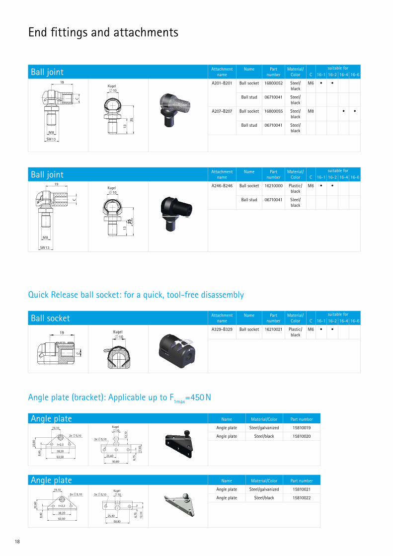
18
Angle plate (bracket): Applicable up to F1max=450 N
Quick Release ball socket: for a quick, tool-free disassembly
Ball socket Attachment name
Name Part number
Material/ Color C
suitable for16-1 16-2 16-4 16-6
A329-B329 Ball socket 16210021 Plastic/ black
M6 • •
10Kugel
19
C
Anschluß Bezeichnung C Material/Farbe Teilenummer
A329 - B329 Kugelpfanne M6 Kunststoff/schwarz 16210021
Kugelpfanne
10Kugel
19
C
Anschluß Bezeichnung C Material/Farbe Teilenummer
A329 - B329 Kugelpfanne M6 Kunststoff/schwarz 16210021
Kugelpfanne
10Kugel
19
C
Anschluß Bezeichnung C Material/Farbe Teilenummer
A329 - B329 Kugelpfanne M6 Kunststoff/schwarz 16210021
Kugelpfanne
Angle plate Name Material/Color Part number
Angle plate Steel/galvanized 15810019
Angle plate Steel/black 15810020
22,6
0
38,20
19,10
63,50
2x 5,10
8,40
t=2,3
10Kugel
25,40
50,80
6,75
17,6
5
3x 5,10 12,1
0
Bezeichnung Material/Farbe Teilenummer
Winkelblech Stahl/verzinkt 15810019
Winkelblech Stahl/schwarz 15810020
Winkelblech
22,6
0
38,20
19,10
63,50
2x 5,10
8,40
t=2,3
10Kugel
25,40
50,80
6,75
17,6
5
3x 5,10 12,1
0
Bezeichnung Material/Farbe Teilenummer
Winkelblech Stahl/verzinkt 15810019
Winkelblech Stahl/schwarz 15810020
Winkelblech
22,6
0
38,20
19,10
63,50
2x 5,10
8,40
t=2,3
10Kugel
25,40
50,80
6,75
17,6
5
3x 5,10 12,1
0
Bezeichnung Material/Farbe Teilenummer
Winkelblech Stahl/verzinkt 15810019
Winkelblech Stahl/schwarz 15810020
Winkelblech
Angle plate Name Material/Color Part number
Angle plate Steel/galvanized 15810021
Angle plate Steel/black 15810022
25,40
50,80
12,1
0
3x 5,10
6,75
10Kugel
2x 5,10
38,20
63,50
19,10
8,40
22,6
0
t=2,3
Bezeichnung Material/Farbe Teilenummer
Winkelblech Stahl/verzinkt 15810021
Winkelblech Stahl/schwarz 15810022
Winkelblech
25,40
50,80
12,1
0
3x 5,10
6,75
10Kugel
2x 5,10
38,20
63,50
19,10
8,40
22,6
0
t=2,3
Bezeichnung Material/Farbe Teilenummer
Winkelblech Stahl/verzinkt 15810021
Winkelblech Stahl/schwarz 15810022
Winkelblech
25,40
50,80
12,1
0
3x 5,10
6,75
10Kugel
2x 5,10
38,20
63,50
19,10
8,40
22,6
0
t=2,3
Bezeichnung Material/Farbe Teilenummer
Winkelblech Stahl/verzinkt 15810021
Winkelblech Stahl/schwarz 15810022
Winkelblech
End fittings and attachments
Ball joint Attachment name
Name Part number
Material/ Color C
suitable for16-1 16-2 16-4 16-6
A201-B201 Ball socket 16800052 Steel/ black
M6 • •
Ball stud 06710041 Steel/ black
A207-B207 Ball socket 16800055 Steel/ black
M8 • •
Ball stud 06710041 Steel/ black
19
SW13
M8
C
25
10Kugel
13
Anschluß Bezeichnung A Material/Farbe Teilenummer
A201 - B201 Kugelpfanne M6 Stahl/schwarz 16800052
A207 - B207 Kugelpfanne M8 Stahl/schwarz 16800055
Kugelzapfen Stahl/schwarz 06710041
Kugelgelenk
19
SW13
M8
C
25
10Kugel
13
Anschluß Bezeichnung A Material/Farbe Teilenummer
A201 - B201 Kugelpfanne M6 Stahl/schwarz 16800052
A207 - B207 Kugelpfanne M8 Stahl/schwarz 16800055
Kugelzapfen Stahl/schwarz 06710041
Kugelgelenk
19
SW13
M8
C
25
10Kugel
13
Anschluß Bezeichnung A Material/Farbe Teilenummer
A201 - B201 Kugelpfanne M6 Stahl/schwarz 16800052
A207 - B207 Kugelpfanne M8 Stahl/schwarz 16800055
Kugelzapfen Stahl/schwarz 06710041
Kugelgelenk
Ball joint Attachment name
Name Part number
Material/ Color C
suitable for16-1 16-2 16-4 16-6
A246-B246 Ball socket 16210000 Plastic/ black
M6 • •
Ball stud 06710041 Steel/ black
SW13
C
M8
19
24,9
0
10Kugel
13
Anschluß Bezeichnung A Material/Farbe Teilenummer
A246 - B246Kugelpfanne M6 Kunststoff/
schwarz 16210000
Kugelzapfen Stahl/schwarz 06710041
Kugelgelenk
SW13
C
M8
19
24,9
0
10Kugel
13
Anschluß Bezeichnung A Material/Farbe Teilenummer
A246 - B246Kugelpfanne M6 Kunststoff/
schwarz 16210000
Kugelzapfen Stahl/schwarz 06710041
Kugelgelenk
SW13
C
M8
19
24,9
0
10Kugel
13
Anschluß Bezeichnung A Material/Farbe Teilenummer
A246 - B246Kugelpfanne M6 Kunststoff/
schwarz 16210000
Kugelzapfen Stahl/schwarz 06710041
Kugelgelenk
25
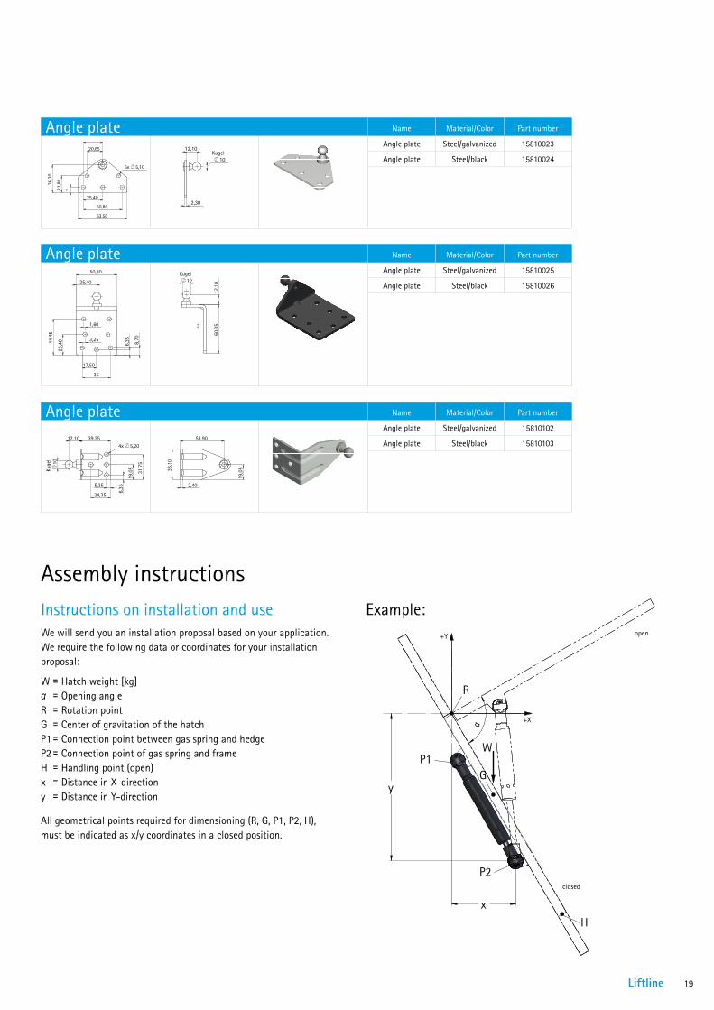
Liftline 19
y
x
R
P1W
P2
G
H
+Y
+X
open
closed
α
Angle plate Name Material/Color Part number
Angle plate Steel/galvanized 15810023
Angle plate Steel/black 15810024 20,65
25,40
50,80
25,40
63,50
721,8
0
36,2
0
5x 5,10
10Kugel
2,30
12,10
Bezeichnung Material/Farbe Teilenummer
Winkelblech Stahl/verzinkt 15810023
Winkelblech Stahl/schwarz 15810024
Winkelblech
20,65
25,40
50,80
25,40
63,50
721,8
0
36,2
0
5x 5,10
10Kugel
2,30
12,10
Bezeichnung Material/Farbe Teilenummer
Winkelblech Stahl/verzinkt 15810023
Winkelblech Stahl/schwarz 15810024
Winkelblech
20,65
25,40
50,80
25,40
63,50
721,8
0
36,2
0
5x 5,10
10Kugel
2,30
12,10
Bezeichnung Material/Farbe Teilenummer
Winkelblech Stahl/verzinkt 15810023
Winkelblech Stahl/schwarz 15810024
Winkelblech
Angle plate Name Material/Color Part number
Angle plate Steel/galvanized 15810025
Angle plate Steel/black 15810026
50,80
25,40
17,50
35
3,25
1,60
6,35 8,70
25,4
044,4
5 60,3
512
,1010
Kugel
3
Bezeichnung Material/Farbe Teilenummer
Winkelblech Stahl/verzinkt 15810025
Winkelblech Stahl/schwarz 15810026
Winkelblech
50,80
25,40
17,50
35
3,25
1,60
6,35 8,70
25,4
044,4
5 60,3
512
,1010
Kugel
3
Bezeichnung Material/Farbe Teilenummer
Winkelblech Stahl/verzinkt 15810025
Winkelblech Stahl/schwarz 15810026
Winkelblech
50,80
25,40
17,50
35
3,25
1,60
6,35 8,70
25,4
044,4
5 60,3
512
,1010
Kugel
3
Bezeichnung Material/Farbe Teilenummer
Winkelblech Stahl/verzinkt 15810025
Winkelblech Stahl/schwarz 15810026
Winkelblech
Angle plate Name Material/Color Part number
Angle plate Steel/galvanized 15810102
Angle plate Steel/black 15810103
10Ku
gel
39,2512,10
5,35
24,35
6,35
19,0
5
31,7
5
4x 5,20
38,1
0
53,90
19,0
5
2,40
Bezeichnung Material/Farbe Teilenummer
Winkelblech Stahl/verzinkt 15810102
Winkelblech Stahl/schwarz 15810103
Winkelblech
10Ku
gel
39,2512,10
5,35
24,35
6,35
19,0
5
31,7
5
4x 5,20
38,1
0
53,90
19,0
5
2,40
Bezeichnung Material/Farbe Teilenummer
Winkelblech Stahl/verzinkt 15810102
Winkelblech Stahl/schwarz 15810103
Winkelblech
10Ku
gel
39,2512,10
5,35
24,35
6,35
19,0
5
31,7
5
4x 5,20
38,1
0
53,90
19,0
5
2,40
Bezeichnung Material/Farbe Teilenummer
Winkelblech Stahl/verzinkt 15810102
Winkelblech Stahl/schwarz 15810103
Winkelblech
Example:
Assembly instructions
All geometrical points required for dimensioning (R, G, P1, P2, H), must be indicated as x/y coordinates in a closed position.
Instructions on installation and useWe will send you an installation proposal based on your application. We require the following data or coordinates for your installation proposal:
W = Hatch weight [kg] α =Opening angle R = Rotation point G = Center of gravitation of the hatch P1 = Connection point between gas spring and hedge P2 = Connection point of gas spring and frame H = Handling point (open) x = Distance in X-direction y = Distance in Y-direction
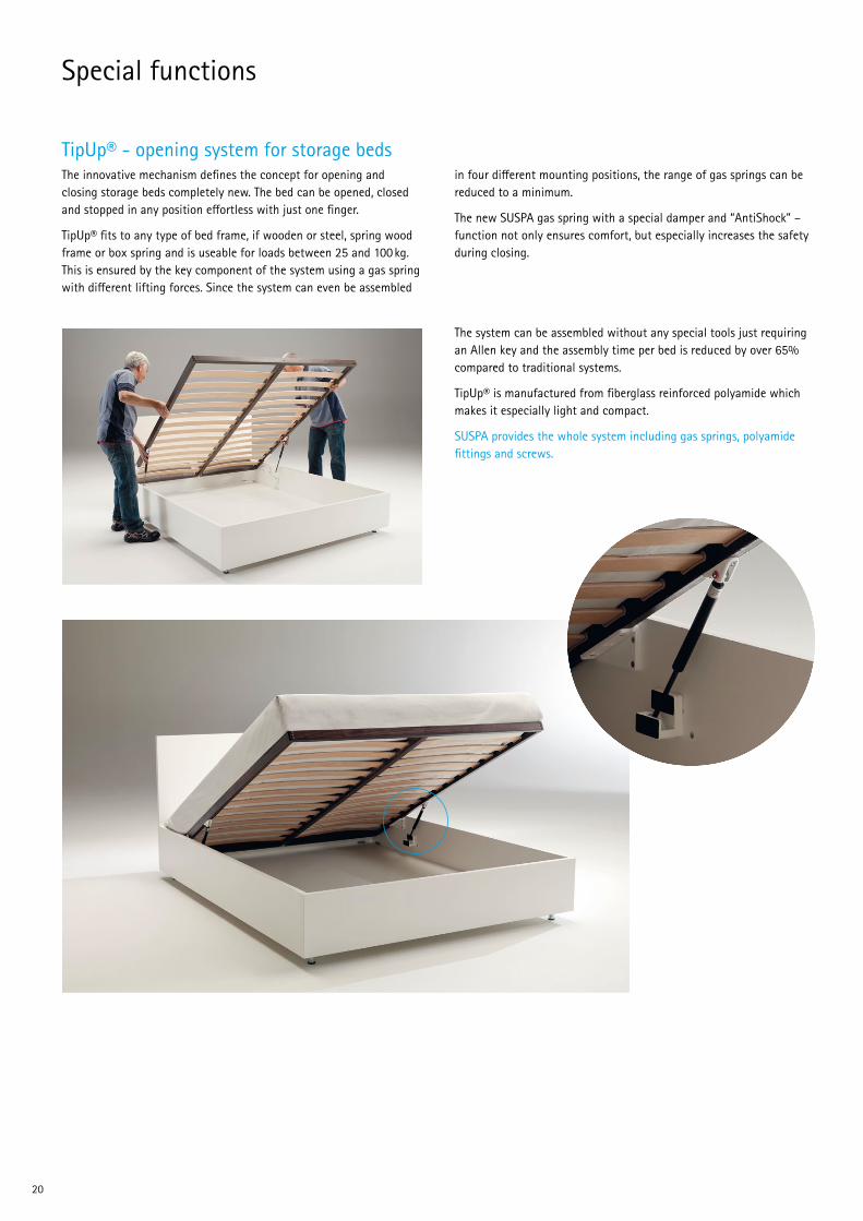
20
Special functions
TipUp® - opening system for storage bedsThe innovative mechanism defines the concept for opening and closing storage beds completely new. The bed can be opened, closed and stopped in any position effortless with just one finger.
TipUp® fits to any type of bed frame, if wooden or steel, spring wood frame or box spring and is useable for loads between 25 and 100 kg. This is ensured by the key component of the system using a gas spring with different lifting forces. Since the system can even be assembled
in four different mounting positions, the range of gas springs can be reduced to a minimum.
The new SUSPA gas spring with a special damper and “AntiShock” –function not only ensures comfort, but especially increases the safety during closing.
The system can be assembled without any special tools just requiring an Allen key and the assembly time per bed is reduced by over 65% compared to traditional systems.
TipUp® is manufactured from fiberglass reinforced polyamide which makes it especially light and compact.
SUSPA provides the whole system including gas springs, polyamide fittings and screws.
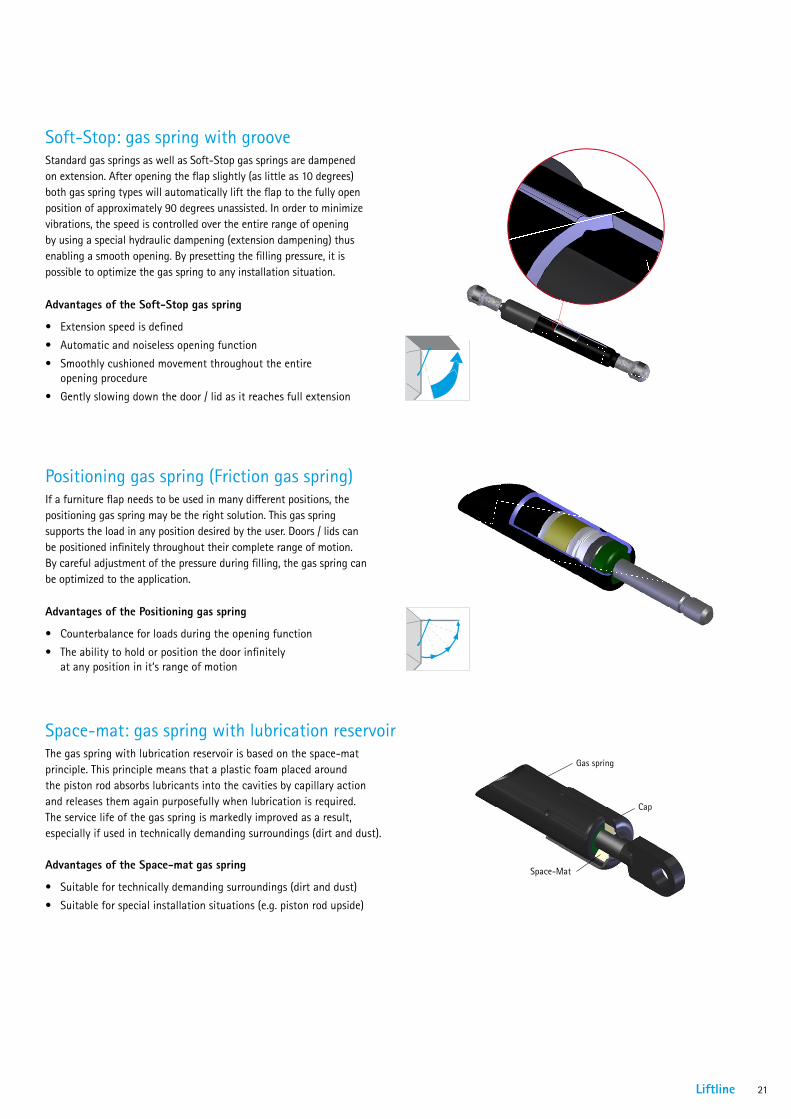
Liftline 21
Kappe
Space-Mat
Gasfeder
Bezeichnung
Bezeichnung
Bezeichnung
Soft-Stop: gas spring with groove
Positioning gas spring (Friction gas spring)
Space-mat: gas spring with lubrication reservoir
Standard gas springs as well as Soft-Stop gas springs are dampened on extension. After opening the flap slightly (as little as 10 degrees) both gas spring types will automatically lift the flap to the fully open position of approximately 90 degrees unassisted. In order to minimize vibrations, the speed is controlled over the entire range of opening by using a special hydraulic dampening (extension dampening) thus enabling a smooth opening. By presetting the filling pressure, it is possible to optimize the gas spring to any installation situation.
If a furniture flap needs to be used in many different positions, the positioning gas spring may be the right solution. This gas spring supports the load in any position desired by the user. Doors / lids can be positioned infinitely throughout their complete range of motion. By careful adjustment of the pressure during filling, the gas spring can be optimized to the application.
The gas spring with lubrication reservoir is based on the space-mat principle. This principle means that a plastic foam placed around the piston rod absorbs lubricants into the cavities by capillary action and releases them again purposefully when lubrication is required. The service life of the gas spring is markedly improved as a result, especially if used in technically demanding surroundings (dirt and dust).
Advantages of the Soft-Stop gas spring
• Extension speed is defined
• Automatic and noiseless opening function
• Smoothly cushioned movement throughout the entire opening procedure
• Gently slowing down the door / lid as it reaches full extension
Advantages of the Positioning gas spring
• Counterbalance for loads during the opening function
• The ability to hold or position the door infinitely at any position in it‘s range of motion
Advantages of the Space-mat gas spring
• Suitable for technically demanding surroundings (dirt and dust)
• Suitable for special installation situations (e.g. piston rod upside)
Gas spring
Cap

22
TouchLift: gas spring that locks in the retracted positionSUSPA TouchLift is a gas spring that locks when fully compressed. One possible application is to hold lid covers in place in the lowered position. The lock is released by gently pressing the cover.
The locking works similar to a ballpoint pen:
• Press once and the gas spring locks in place
• Press once more and the gas spring extends
Applications
By using the SUSPA TouchLift gas spring, furniture elements can be retracted so that their lid cover is flush with the respective surface. The objects can be raised and retracted simply by pressing the cover.
Application examples
• Retracting flat screens
• Retracting outlet strips
• A minibar to be retracted
• Lifting and lowering functions for head rests or arm rests of sofas
Advantages
The main advantages of the SUSPA TouchLift is the very low noise and and the 7mm travel of release.
The TouchLift gas spring works without electricity, therefore, no cables or batteries are required and no electricity costs are incurred. Its service life corresponds with that of a classic gas spring, i. e. approximately 50,000 cycles.
compressed locked
extended
Special functions
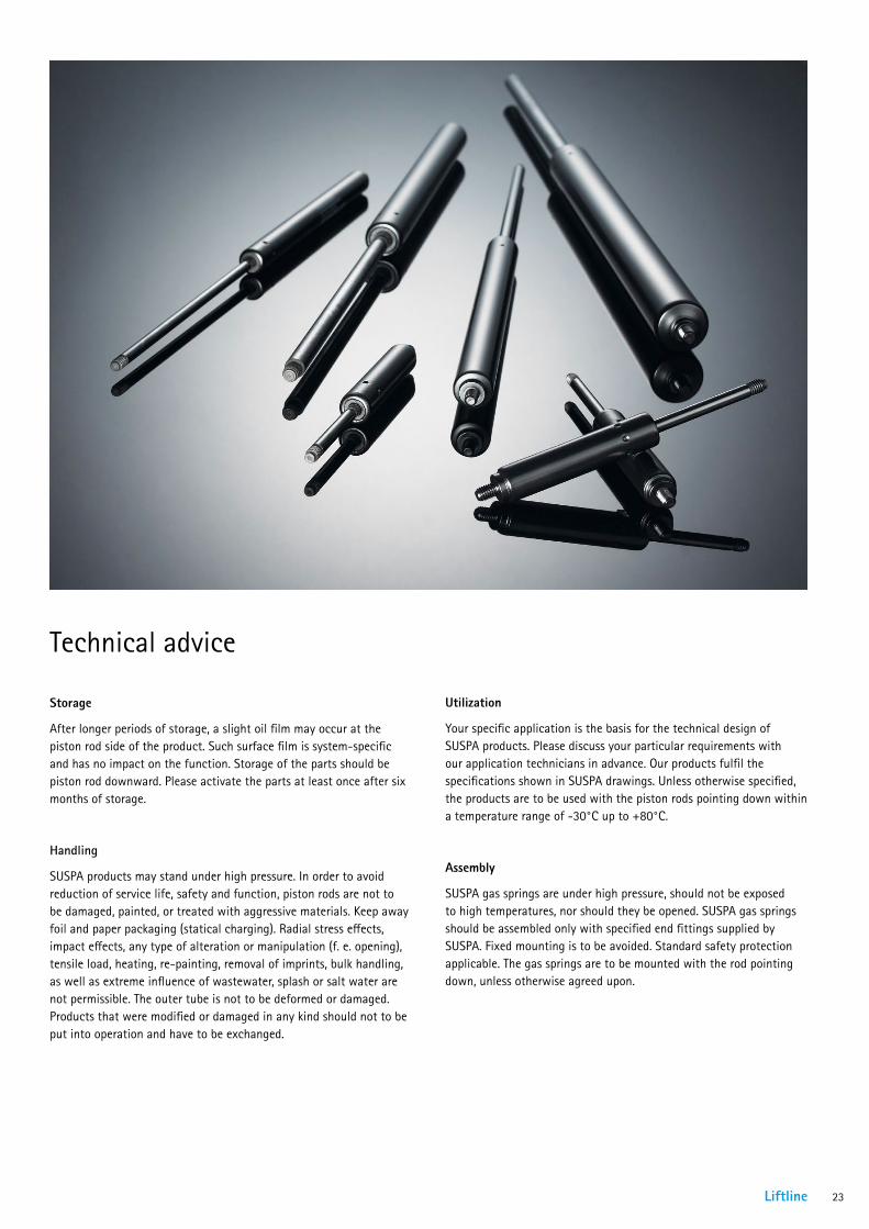
Liftline 23
Storage
After longer periods of storage, a slight oil film may occur at the piston rod side of the product. Such surface film is system-specific and has no impact on the function. Storage of the parts should be piston rod downward. Please activate the parts at least once after six months of storage.
Handling
SUSPA products may stand under high pressure. In order to avoid reduction of service life, safety and function, piston rods are not to be damaged, painted, or treated with aggressive materials. Keep away foil and paper packaging (statical charging). Radial stress effects, impact effects, any type of alteration or manipulation (f. e. opening), tensile load, heating, re-painting, removal of imprints, bulk handling, as well as extreme influence of wastewater, splash or salt water are not permissible. The outer tube is not to be deformed or damaged. Products that were modified or damaged in any kind should not to be put into operation and have to be exchanged.
Technical advice
Utilization
Your specific application is the basis for the technical design of SUSPA products. Please discuss your particular requirements with our application technicians in advance. Our products fulfil the specifications shown in SUSPA drawings. Unless otherwise specified, the products are to be used with the piston rods pointing down within a temperature range of -30°C up to +80°C.
Assembly
SUSPA gas springs are under high pressure, should not be exposed to high temperatures, nor should they be opened. SUSPA gas springs should be assembled only with specified end fittings supplied by SUSPA. Fixed mounting is to be avoided. Standard safety protection applicable. The gas springs are to be mounted with the rod pointing down, unless otherwise agreed upon.

SUSPA GmbHIndustriestr. 12-14 90518 Altdorf Germany
Telephone +49 9187 930 355 Fax +49 9187 930 311
E-mail [email protected] Internet www.suspa.com 09
/201
5
www.suspa.com