garrett gas train instruction manual - expotechusa
TRANSCRIPT

Garrett Gas Train ® Instruction Manual Part No. 552010001EA Rev. C


TABLE OF CONTENTS SECTION PAGE NO. 1 Introduction...........................................................................................................................1 2 Safety Considerations ..........................................................................................................3 3 Procedure for Gas Train Analysis (Sulfides - Water Based Fluids)....................................5 4 Procedure for Gas Train Analysis (Sulfides - Oil Based Fluids) .........................................9 5 Procedure for Gas Train Analysis (Carbonates) ...............................................................13 6 Cleaning and Maintenance.................................................................................................17 7 Equipment and Specifications ...........................................................................................19 8 Pressure Regulator Maintenance......................................................................................23 9 Parts List............................................................................................................................25 TABLE 1 Draeger Tube Identification, Sulfide .....................................................................................7 2 Draeger Tube Identification, Carbonates ...........................................................................15 FIGURE 1 Garrett Gas Train (Sulfides Analysis water based drilling fluids).........................................4 2 Garrett Gas Train (Sulfides Analysis oil based drilling fluids) ..............................................8 3 Garrett Gas Train (Carbonates Analysis) ..........................................................................11 4 Model 337 Pressure Regulator (Exploded View) ...............................................................22

SECTION 1
INTRODUCTION A number of gases are generally present in the drilling fluid during the drilling operation. Two of these gases may be identified and their concentration determined using the Garrett Gas Train. These are undesirable gases but their presence and concentration are important. These two gases are Hydrogen Sulfide (H2S) and Carbon Dioxide (CO2). The presence of Hydrogen Sulfide Gas is important because it is toxic and dangerous to human health. It is a health hazard in concentrations in air as low as 20 parts per million. Hydrogen Sulfide can be fatal in higher concentrations. The Garrett Gas Train analyses can warn of the risk of increasing concentrations of sulfides in drilling fluid and possible release of Hydrogen Sulfides into the atmosphere . The presence of Carbon Dioxide (CO2) in the drilling fluid is important because it can cause severe corrosion and damage to the drilling rig equipment. Measurement of the concentrations of carbonates permits calculation of treatment necessary for corrosion control. The Garrett Gas Train separates the gases from liquids, thereby preventing contamination of the H2S or CO2 detecting Draeger tubes by the liquid phase. A Draeger tube is the preferred H2S detector for quantitative sulfide analysis. A Draeger tube responds to H2S by progressively darkening along its length as the H2S reacts with the reagent. NOTE: A hydrogen sulfide test paper disk can be accommodated in the Garrett
Gas Train for routine tests until evidence of the presence of H2S is noted by discoloration of the hydrogen sulfide test paper, then a Draeger tube should be used for quantitative analysis.
Total soluble sulfides include the sulfide (S=) and bisulfide (HS) ions. Two types of Draeger tubes are used to adequately span the range of hydrogen sulfide concentrations that may be found in water based drilling fluid filtrates and in oil based drilling fluids. The low-range Draeger tube, H2S 100/a, is white until H2S turns it brownish-black. The high-range Draeger tube, H2S 0.2%/A, is pale blue until H2S turns it jet black. No known common drilling fluid component or contaminant causes this coloration of the Draeger tubes as does H2S. The Draeger tubes change color by reacting to a given quantity of H2S therefore the length of the darkened section of the tube depends not only on the concentration of the sample gas but also on the flow rate and the length of time the sample flows through the Draeger tube. To relate the divisions on the Draeger tube to the parameters of the Garrett Gas Train, a tube factor for each tube has been calculated. Refer to Table 1 for the tube factors to be used to calculate the hydrogen sulfide concentration and Table 2 for the tube factor for the carbonate concentration. For H2S in Oil-Based drilling fluids, the same two Draeger tubes are used as for water based drilling fluid. The technique of running the analysis is modified to analyze the oil drilling fluid instead of the filtrate in order to capture all the "active sulfides". Active sulfides are typically the neutralization products of H2S and lime plus any un-reacted H2S. Utilizing a weak acid in the Garrett Gas Train, the oil drilling fluid test liberates H2S gas from active sulfides but not from inert sulfides. Whole drilling fluid is used in this test rather than the filtrate.

The concentration of soluble carbonates in the water based drilling fluid filtrate can be determined by the following method. Total soluble carbonates include carbon dioxide (CO2), the carbonate (CO3) and bicarbonate (HCO3) ions. Drilling fluid filtrate is acidified in The Garrett Gas Train, converting all carbonates to CO2 which is then evolved by bubbling an inert gas through the sample. The gas stream is collected in a one liter bag and subsequently drawn through a Draeger tube at a fixed flow rate. The CO2 Draeger tube responds to the CO2 passing through it by progressively staining along its length as the CO2 reacts with a chemical which causes a crystal indicator to turn purple. The stain length is sensitive to the amount of CO2 present, but it also responds to the CO2 distribution, total volume, and flow rate of gas passed through the tube.

SECTION 2 SAFETY CONSIDERATIONS Safe operation of the Garrett Gas Train requires that the operator be familiar with the proper operation and potential hazards associated with pressurized equipment. Pressurizing the Garrett Gas Train Cell, even though it is to a low pressure, poses the potential hazards of the cell or associated pressurization equipment leaking and/or releasing sample gas or pressurizing gas which could cause serious injury. Several precautions that should be observed are listed below: ? Usually Carbon Dioxide is the choice of pressurizing gas when running Sulfides analysis. Nitrous Oxide
(N2O) or Nitrogen must be used for the Carbonates analysis. Never connect the Garrett Gas Train to any other gas. If Nitrogen is used it must be supplied from an approved Nitrogen gas cylinder. Nitrogen Cylinders must be secured and meet all safely standards. Refer to Section 9E (first four items) for the optional equipment required for Nitrogen connection. Carbon Dioxide and Nitrous Oxide are normally supplied in small cartridges which contain about 900 psi (6206 kPa) pressure. They are primarily used for pressurization. Do not allow these cartridges to be heated or exposed to fire. They can explode if overheated.
? Maintain pressure regulators in good condition. Never use oil on pressure regulators. Leaking
pressurization systems should be repaired or replaced. Gauges, fittings and hoses should be kept in good condition and leaks should be found and corrected. Refer to REGULATOR REPAIR, Section 8. Periodically test the safety relief valve attached to the regulator. Never plug or bypass this safety valve.
? When preparing to pressurize the Garrett Gas Train Cell always make sure the regulator is closed (Tee
screw backed all the way out, counterclockwise). ? Hydrogen Sulfide (H2S) smells like rotten eggs. Prolonged exposure to this gas will deaden a persons
sense of smell and the person will assume the danger is over when in fact the Hydrogen Sulfide concentrations may be higher and the person may be in very serious danger.
CAUTION
WHEN COLLECTING (H2S) SAMPLES FOR THE GARRETT GAS TRAIN, USE EXTREME CAUTION TO AVOID BREATHING ANY HYDROGEN SULFIDE. USE AN APPROVED BREATHING MASK OR BREATHING AIR BACK PACK.

Fig. 1 - GARRETT GAS TRAIN SULFIDES ANALYSIS WATER BASED DRILLING FLUIDS (Numbers refer to Sections 9A through 9D PARTS LIST)

SECTION 3 PROCEDURE FOR GAS TRAIN ANALYSIS (SULFIDES - WATER BASED DRILLING FLUIDS)
A. Set Up For Water Based Drilling Fluid Filtrate, Sulfides. (Refer to Fig. 1). If it is not known that CO2 gas was used in the last test, the regulator, tubing, and dispersion tube
should be purged with CO2 gas for two minutes. NOTE If is desired to run the sulfides test using a hydrogen sulfide test paper disk
instead of the Draeger tube, fit the test disc under the O-ring of Chamber 3 of the Garrett Gas Train. The hydrogen sulfide test paper, although not preferred for quantitative analysis, will show the presence or absence of sulfides in the sample, and under proper test conditions (flowing CO2 for fifteen (15) minutes can provide an estimate of the amount of sulfides when compared to a Hach color chart.
Install the 3 in. (7.6cm) tube in place of the Draeger tube in Chamber 3 and connect the tube to the flowmeter to it. Omit steps A-6, A-7, B-6, and B-7 below. 1. Be sure the gas train is clean, dry, and on a level surface, with the top [13] removed. 2. Add 20 ml deionized water to Chamber 1. (Refer to Fig. 1). 3. Add 5 drops W-300 octanol defamer to Chamber 1. 4. Assemble the top [13] onto the gas train body [12] using the four thumb screws [14]. Make sure
the "O" rings [27, 28] have properly sealed by noting flattened tops all the way around "O" ring circumference.
5. Adjust the dispersion tube [7] in Chamber 1 to approximately 0.5 cm above the bottom. 6. Select the proper Draeger tube for the expected concentration of sulfides. (Refer to Table 1, for
sample volumes, and selection of Draeger tube range). 7. Apply Lubriseal onto the 7 mm diameter of both ends of Draeger tube Beak the tips off both
ends of the Draeger tube by inserting the tips in the hole in bracket [44] near the bottom of chamber 1. With the arrow on the Draeger tube pointed upward, insert Draeger tube [33 or 34] into the loosened connector [15] on top of Chamber 3 until first line on scale is level with the top of the connector. Tighten tubing connector nut hand tight. Fit the Tygon tube [25] from the flowmeter inlet fitting [22] onto top of Draeger tube.
8. Make sure the Luer Cap [16] is secured on the sample inlet Luer Fitting [17]. 9. Back out the regulator tee screw [5] until it turns freely. 10. Install and puncture the CO2 cartridge [32], or open the supply pressure, if Nitrogen is being
used. 11. Adjust the regulator to 5 psi. (34 kPa) or gauge [21]. NOTE: Do not attempt to pressurize higher than 10 psi. (69 kPa). 12. Adjust needle valve [6] for a flow of 0.3 to 0.5 liters/minute read on flowmeter [29].

13. Flow CO2 carrier gas for 15-seconds to purge air from the system. Check the system for leaks as described below.
14. Close the discharge at the top of the flowmeter [29] by fitting a piece of Tygon Tubing [25] over
the barbed insert [24] and plugging or pinching the tubing to seal it closed. 15. Verify approximately 5 psi pressure on gauge [21], back out the Tee Screw on the regulator [5]
until it turns freely to shut of the carrier gas supply. 16. Allow the system to remain pressurized approximately 5 minutes and observe the gauge
reading. If less then 3 psi, use soap solution to determine source of leak. 17. If pressure test is passed, remove tubing plug and readjust regulator to about 5 psi. 18. Shut off the CO2 carrier gas at the needle valve [6]. B. Sample Analysis The estimated concentration of soluble sulfides will determine the volume of filtrate that will be required.
(Refer to Table 1). Care should be taken during drilling fluid sampling, filtration, and analysis to avoid extensive exposure of sample to the air because sulfides are rapidly lost by air oxidation.
1. Using an API Low Temperature / Low Pressure Filter Press, run a filtration test on a sample of
the water based drilling fluid to be analyzed and collect a sufficient volume of solids-free filtrate for analysis. (Refer to Table 1 for volume required).
2. Using a 10 ml hypodermic syringe [30], inject the required volume of solids-free filtrate sample
into Chamber 1 through the top injection port [8]. 3. Using a clean syringe, slowly inject 10 ml sulfuric acid solution into chamber 1 through the
injection port [8]. Gently shake the gas train to mix acid with sample in Chamber 1. CAUTION MOISTURE IN THE TRAIN CAN CAUSE THE BALL IN THE FLOWMETER
TO FLOAT ERRATICALLY AND MAY AFFECT THE ACCURACY OF THE DRAEGER TUBE READING.

4. Immediately restart the CO2 carrier gas flow by turning the needle valve [6] to a steady flow of about 0.3 liters/minute as read on the flowmeter for 4 minutes for paper disc Sulfide/ no Sulfide test. One cartridge is sufficient for either size Draeger tube and should provide 15 to 20 minutes of charge at 0.3 liters/minute flow rate. If the hydrogen sulfide test paper disks are used, three to four tests can be made with one cartridge, but the paper disc should not be used more than three or four times. For any quantitative test, the full 15 minutes must be run.
5. Observe changes in appearance of the Draeger tube. Before the front starts to smear, note and
record the maximum darkened length (in units marked on the tube). Although the front may attain a diffuse and "feathery" coloration, continue flowing for a total of 15 minutes. If sulfites are present in the sample, an orange color (caused by SO2) may appear in the high-range tube ahead of the black front. When recording darkened length, the orange SO2 region should be ignored.
6. When de-pressurizing, shut off the supply pressure by closing the two shut off valves [6] on the
CO2 manifold. If a Nitrogen system is being used, close the cylinder valve. Bleed the system of pressure, then, back out the regulator Tee screw.
7. Using the measured sample volume, the Draeger tube's maximum darkened length, and
Draeger Tube Factor from Table 1, calculate sulfides in the sample: 1 TABLE 1
Draeger Tube Identification-Sample Volume & Tube Factor for Various Sulfide Ranges
Sulfide Range (mg/L) Sample Volume (ml) Draeger Tube Identification (See
Tube Body)
Tube Factor (Used In Equation)
1.2 to 24 10.0
2.4 to 48 5.0 H2S 100/a 0.12*
4.8 to 96 2.5
60 to 1020 10.0
120 to 2040 5.0 H2S 0.2%/a 1500**
240 to 4080 2.5
* Tube Factor "0.12" applies to new style tubes, H2S 100/a (catalog no. CH-291-01), with calibration marks from 100 to 2000. Older style tubes with 1 to 20 scale use a Tube Factor of 12. ** Tube Factor "1500" applies to new style tubes, H2S 0.2%/a (catalog no. CH-281-01), with calibration marks 0.2 to 7.0. Older style tubes with 1 to 17 markings still use a Tube Factor of "600" times the ratio: "Batch Factor"/0.40. (A "Batch Factor" was stamped on boxes of old style tubes; there is not a "Batch Factor" for new style tubes.)

Fig. 2 - GARRETT GAS TRAIN SULFIDES ANALYSIS OIL BASED DRILLING FLUIDS (Numbers refer to Sections 9A through 9D PARTS LIST)

SECTION 4 PROCEDURE FOR GAS TRAIN ANALYSIS (SULFIDES - OIL BASED DRILLING FLUIDS) A. Set Up Of The Garrett Gas Train For Oil Based Drilling Fluid, H2S Analysis. (Refer to Fig. 2) . If it is not known that CO2 gas was used in the last test, the regulator, tubing, and dispersion tube should
be purged with CO2 gas for two minutes. 1. Be sure the gas train is clean, dry, with the top [13] removed. Set the body [12] of the Garrett
Gas Train on the magnetic stirrer [36], positioning the center of chamber 1 over the center of the stirrer. Place the stirring bar [37] in chamber 1. (Refer to Fig. 2).
2. Add 20 ml of citric acid/demulsifier/isopropyl alcohol solution to Chamber 1 (Refer to Fig. 2). 3. Add 10 drops W-300 octanol defamer to Chamber 1. (Refer to Fig. 2). 4. Assemble the top [13] onto the gas train body [12] using the four thumb screws [14]. Make sure
the "O" rings [27, 28] have properly sealed, by noting a flat portion in "O" ring profile all around the circumference of ring.
5. Adjust the dispersion tube [7] in Chamber 1 to be slightly above the liquid level in that chamber by
loosening and tightening connector [15]. 6. Select the proper Draeger tube [33 or 34] for the expected concentration of sulfides. (Refer to
Table 1, for sample volumes and selection of Draeger tube range.) 7. Apply Lubriseal onto the 7mm diameter of both ends of Draeger tube. Break the tips off both
ends of the Draeger tube by inserting the tips in the hole in bracket [44] near the bottom of chamber 1. With the arrow on the Draeger tube pointed upward, insert Draeger tube [33 or 34] into the loosened connector [15] on top of Chamber 3 until first line on scale is level with the top of the connector. Tighten tubing connector nut hand tight. Fit the Tygon tube [25] from the flowmeter inlet fitting [22] onto top of Draeger tube.
8. Make sure the Luer Cap [16] is secured on the sample inlet Luer Fitting [17]. 9. Back out the regulator tee screw [5] until it turns freely. 10. Install and puncture the CO2 cartridge [32], or open the supply pressure, if Nitrogen is being
used. 11. Adjust regulator to about 5 psi (35 kPa) on gauge [21]. Then adjust needle valve [6] for a flow of
0.3 to 0.5 liters/minute on flowmeter (29). 12. While keeping the dispersion tube [7] "frit" above the liquid level in chamber 1, flow CO2 carrier
gas for 15-seconds to purge air from the system and check for leaks. (Refer to section 3-A step 13 - 17), then shut off the CO2 carrier gas at the needle valve [6].

B. Sample Analysis The estimated concentration of soluble sulfides will determine the volume of oil base drilling fluid that will
be required. (Refer to Table 1, "Sample Volume ml). Care should be taken during sampling and analysis to avoid extensive exposure of sample to the air because sulfides are rapidly lost by air oxidation.
1. Load a 10 ml syringe without needle [30] with a sample of the oil based drilling fluid to be tested.
The size of this sample will be as determined from Table 1 plus 0.1 ml of excess sample. The excess sample (0.1 ml) compensates for the hold-up volume inside the injection fitting.
2. Wipe the outside of the syringe to clean off any oil base drilling fluid that is on it as a result of
filling the syringe. Especially clean the area on the tip where the syringe will connect to the injection fitting.
3. Remove the cap [16] from the sample inlet Luer Fitting [17] on the side of chamber 1. 4. Connect the loaded hypodermic syringe to the syringe Luer fitting by inserting and turning 1/4
turn to the right. (Refer to Fig. 2) 5. Turn on the magnetic stirrer [36]. Adjust its speed of the stirring bar [37] until a vortex in the fluid
is formed then carefully lower the gas dispersion tube [7] into the liquid to a point just above the rotating stirring bar [37]. Be careful not to let the dispersion tube hit the stirring bar.
6. Very slowly inject the sample from the syringe then lock the syringe closed with the syringe lock
clip [35]. Increase the stirring speed to improve dispersion and to prevent the oil drilling fluid from sticking to the walls of Chamber 1. Continue the stirring about one minute.
7. Restart the CO2 carrier gas flow by turning the needle valve [6] to a steady flow of about 0.3
liters/minute as read on flowmeter [29] for 15 minutes. A second cartridge may be required for the full 15 minutes.
8. Observe changes in appearance of the Draeger tube [33 or 34] which will begin at the inlet end
(lower end). Note and record the maximum darkened length (in units marked on the tube) before the front starts to "feather" and smear. Although the front may attain a diffuse and "feathery" coloration, continue flowing for a total of 15 minutes. If sulfites are present in the sample, an orange color (caused by SO2) may appear in the high-range tube ahead of the black front. When recording darkened length, the orange SO2 region should be ignored.
9. Using the measured sample volume (not including the 0.1 ml hold up volume), the Draeger tube
maximum darkened length, and Draeger Tube Factor (Table 1), calculate sulfides in the oil drilling fluid sample.
2

Fig. 3 GARRETT GAS TRAIN (CARBONATES ANALYSIS WATER BASED DRILLING FLUIDS (Numbers refer to Sections 9A through 9D PART LIST


SECTION 5 PROCEDURE FOR GAS TRAIN ANALYSIS (CARBONATES) If it is not known that N2O gas was used in the last test, the regulator, tubing, and dispersion tube should be purged with N2O gas for two minutes. A. Set Up Of The Garrett Gas Train For Water Based Drilling Fluid Filtrate, Carbonates Analysis. (Refer to
Fig. 3). 1. Be sure the gas train is clean, dry, and on a level surface, with the top [13] removed. 2. Add 20 ml deionized water to Chamber 1. 3. Add 5 drops W-300 octanol defamer to Chamber 1. 4. Assemble the top [13] onto the gas train body [12] using the four thumb screws [14]. Make sure
the "O" rings [27 and 28] have properly sealed by noting flattened tops all the way around "O" ring circumference.
5. Adjust the dispersion tube [7] in Chamber 1 to approximately 0.5 cm above the bottom. 6. Apply Lubriseal lubricant to and insert the 5/16" X 3" long plastic tube [43] into the tubing
connector [15] on top of Chamber 3. Tighten the connector nut hand tight. 7. Make sure the Luer Cap [16] is secured on the sample inlet Luer Fitting [17]. 8. With regulator Tee Handle [5] backed off, install and puncture an N2O cartridge [38]. 9. Adjust regulator to about 5 psi (35 kPa) on gauge [21]. Then adjust valve [6] for a flow of 0.3 to
0.5 liters/minute as read on flowmeter [29]. (For maintenance instructions for regulators, Refer to Section 8 and Fig. 4).
10. Flow N2O for a 10-second period to purge air from the system. Check for leaks. Refer to
Section 3-A, steps 13 - 17. Shut off the N2O carrier gas at the needle valve [6]. 11. Connect the gas bag [40] and stopcock [42] to the hand pump [41] using tubing [25]. Start with
the bag essentially empty. Fully depress and release the hand pump. When the bag is completely empty and free of leaks, the pump will remain depressed for several minutes. If leakage is detected, check the pump and all connections. To check the pump alone, insert a sealed Draeger tube [39] into the pump opening and depress bellows. It will remain depressed if the pump does not leak.
12. With the bag fully collapsed, close the stopcock and disconnect the pump. Install the flexible
tubing [25] from the stopcock and bag onto the top barbed tubing connector of the flowmeter [24].
13. Using an API low temperature filter press and standard filtration procedure, collect a sufficient
volume of solids-free filtrate for analysis. B. Sample Analysis 1. Using one 10 ml syringe and needle [30], inject a measured volume of solids-free filtrate sample
into Chamber 1 through the top injection port [8]. (Refer to Table 2, for using estimated concentration of CO2 to determine sample volume).
2. Using another 10 ml syringe and needle, slowly inject 10 ml sulfuric acid solution into Chamber 1

through the injection port [8]. Gently shake the gas train to mix acid with sample in Chamber 1. 3. Open the stopcock [42] on the gas bag [40]. Restart and adjust the gas flow by turning the
needle valve [6] to a steady flow of 0.1 liters per minute as read on flowmeter [29] for 10 minutes. This will fill the gas bag with 1 liter of gas. At the end of 10 minutes, shut off gas flow by closing valve [6] and close the stopcock [42]. Immediately proceed to next step.
4. Apply Lubriseal to 7mm diameter at both ends of the tube. Break off the tips of both ends of the
Draeger tube [39] by inserting the tip in the hole in the bracket [44] near the bottom of chamber 1. Remove the tubing [25] from flowmeter barbed tubing connector [24] and install it onto the upstream end of the Draeger tube. Observe that an arrow on the Draeger tube indicates gas flow direction. Attach the Draeger tube hand pump [41] to the downstream end of Draeger tube [39].
5. Open the stopcock [42] on the bag [40]. With steady hand pressure, fully depress hand pump
[41]. Release pump so that gas flows out of bag and through the Draeger tube. Operate the pump and count the strokes until the bag is empty. (10 strokes should empty the bag. The need for more than 10 strokes indicates leakage has occurred and test results will not be correct.
6. Using the measured Sample Volume, the Draeger Tube's Stain Length, and Tube Factor from
table 2, calculate total soluble carbonates (CO3 + HCO3) in the filtrate sample, using the equation below:
GGT Carbonates, mg / l =
(Stain Length) x (2.5)(Sample Volume, cm )3
3

TABLE 2
Draeger Tube Identification-Sample Volume & Tube Factor for Carbon Dioxide Ranges
Carbonate Range (mg/L)
Sample Volume (ml) Draeger Tube Identification (See Tube Body)
Tube Factor (Used In Equation)
25 to 750 10.0 CO2 100 a 2.5
50 to 1500 5.0
250 to 7500 1.0
Tube Factor "2.5" applies to new style tubes, CO2 100/a (catalog no. 1801811), with calibration marks IN PARTS PER MILLION BY VOLUME. Older style tubes (CH-308-01 are scaled to use a 25,000 Tube Factor.


SECTION 6 CLEANING and MAINTENANCE To clean the Gas Train, adjust the pressure regulator [5] counterclockwise until the pressure on the diaphragm is released. Remove the Draeger tube [33, 34 or 39], the plastic tube [43] from connector [15] on the top above chamber 3. Remove Gas Train Top [13] by loosening the four thumb screws [14], then remove dispersion tube [7] from the top above chamber 1. Using a soft brush, wash out all the chambers with warm water and mild detergent. Use a pipe cleaner to clean the passages between chambers. Wash, rinse, and then blow out the dispersion tube with a dry gas. Rinse the unit with deionized water and allow to drain dry. Inspect the "O" rings for cuts, hardening or flat spots. Make sure the "O" ring grooves are clean. Inspect the flowmeter [29] for contamination and/or sticking of the ball. If required the flowmeter may be dissembled from the gas train cover [13] by removing screw [2]. The plug in the top of the flowmeter can be removed to gain access to the ball and the tube bore. Using a soft brush, wash all graduates, syringes and other laboratory containers with warm water and mild detergent. Wash, rinse, and then blow out the dispersion tube [7] with a dry gas. For maintenance of the pressure regulator [5] refer to Section 8.


SECTION 7 EQUIPMENT AND SPECIFICATIONS The apparatus, laboratory supplies, and reagents listed are required to perform one or more of the three analyses utilizing the Garrett Gas Train. A. Equipment required for all tests.
1. Garret Gas Train apparatus, shown in Figs. 1, 2, and 3, consists of:
Transparent plastic gas train
Chamber 1 on regulator [5] and gauge [21] side of Gas Train.
Depth 3.54 in. (90mm) Diameter 1.52 in. (39mm)
Chambers 2 & 3 Depth 3.54 in. (90mm) Diameter 1.18 in. (30mm)
Passages between chambers 0.08 in. (2mm)
2. Pressure Regulator Assembly
Pressure Regulator High pressure - Low flow, Chrome plated
Pressure gauge 30 psi (207 Kpa), dial 1.5 in. (38 mm), chrome plated
Needle valve (bleed valve) 1/8 in NPT, Chrome plated
Relief valve Adjustable 5 - 25 psi (34.5 -172.5 Kpa)
Pressure Source CO2 or N2O cartridges
3. Flowmeter Floating-ball, Plastic body 0.06 - 0.5 LPM (60 - 500 cm3 per minute) air
4. Hypodermic syringe 10.0 ml glass or plastic (inert to oil based drilling fluids) Luer-lok.
5. Dispersion Tube PYREX glass
Stem length 7.1 in. (180 mm)
Stem diameter 0.315 in. (8.0 mm)
Frit Medium porosity
Frit Diameter Diameter 1.18 in (30 mm)
6. Graduated cylinder (not shown) 25 ml TC. Glass 0.2 ml divisions, +/- 0.2 ml

B. Equipment required for Sulfides in water base drilling fluid in addition to that listed in "A" above.
1. Inert carrier gas supply CO2 cartridges
2. Detector Draeger tubes [2] Hydrogen Sulfide Test Paper Disks
Draeger tube, low range Marked H2S 100/a (No. CH-291-01), 100 to 2000 PPM
Draeger tube, high range Marked H2S 0.2%/A (NO. CH-281-01), 0.2 % to 7.0%
3. Sulfuric acid 5N, reagent grade
4. W-300 Surflo Octanol defoamer Dropper bottle
C. Equipment required for Sulfides in oil base drilling fluid in addition to that listed in "A" above.
1. Magnetic Stirrer w/Stirrer Bar* 1/4 inch (0.63 cm) diameter x 1 inch (2.54 cm) long stirring bar, coated with glass or TEFLON.*
2. Inert carrier gas supply CO2 cartridges
3. Detector Draeger tubes [2]
Draeger tube, low range Marked H2S 100/a (No. CH-291-01), 100 to 2000 PPM
Draeger tube, high range Marked H2S 0.2%/A (NO. CH-281-01), 0.2 % to 7.0%
4. Demulsifer Citric acid/demulsifer/isopropyl alcohol solution
5. W-300 Surflo Octanol defoamer Dropper bottle
* (Optional equipment with this instrument) D. Equipment required for Carbonates in water base drilling fluid in addition to that listed in "A" above.
1. Draeger CO2-analysis tube Marked CO2 100/a (No. 1801811)
2. Draeger Alcotest gas bag. One-liter
3. Draeger Multigas Detector Hand-operated vacuum pump, Model 31
4. Stopcock (2-way bore), 8 mm glass
5. Sulfuric acid 5N, reagent grade
6. W-300 Surflo Octanol defoamer Dropper bottle
7. N2O gas cartridges Nitrous Oxide gas inert to Carbonates

NOTE Nitrogen (N2) bottle with a low-pressure regulator can be used for both sulfides
and carbonates. It can be connected to the Garrett Gas Train as follows: 1. Remove pipe plug [1]. (Refer to Figs. 1, 2 & 3) 2. Replace plug with (33513) 1/8 NPT x Eastman adapter. 3. Connect Regulator (34265) to a nitrogen cylinder such as (34005). 4. Connect (31700) 3 ft. hose from regulator to Eastman Adapter.

Fig. 4 - MODEL 337 PRESSURE REGULATOR (EXPLODED VIEW)

SECTION 8 PRESSURE REGULATOR MAINTENANCE A. Pressure Regulator Maintenance and Repair Most regulator troubles are caused by leaking fittings or faulty pins and seats. Rarely does a diaphragm
rupture. If regulator will not hold pressure, check the fittings which are screwed into it. This is done by applying pressure to the system and looking for escaping gas in the form of bubbles. There are two methods of doing this. One method is to apply soap suds to the fitting areas, the other is to carefully immerse all but the pressure gauge in a container of water. If leaks are apparent, disassemble and apply tape thread sealant to the threads.
CAUTION DO NOT USE OIL BASED THREAD DOPE OR OIL IN ASSEMBLING ANY REGULATOR. B. Replacing the seat and pin. If regulator connections do not leak, the seat and pin probably need replacement. Use the following
procedure. (Refer to items on Fig. 4). 1. Using a wrench on the hex of the spring case, unscrew the spring case. All parts down to and
including the diaphragm will remain in the spring case. 2. Remove the thrust plate. 3. Unscrew the retainer and remove the seat with the pin. 4. Clean and inspect the regulator for evidence of dirt or drilling fluid in the regulator body. An outlet
filter (33720) is available to prevent this problem. 5. Replace the pin and seat. 6. Re-assemble the regulator. C. Verify the relief valve will relieve at 12-14 psi (88-96 kPa) pressure. Periodically test the safety relief
valve which is pointed downward and attached to the regulator. (Refer to item 31 of Fig.1,2,and 3). Never plug or bypass this safety valve.

SECTION 9 PARTS LIST A. PARTS REQUIRED FOR ALL TESTS (Item numbers refer to Figs. 1,2 or 3) (N/S Refer to Items not shown)
ITEM NO. PART NO. QTY DESCRIPTION
1 14015 1 Plug, 1/8 Pipe 2 31515 1 Screw, 1/4 - 20 x 1/2, Flowmeter, Mount Bracket
3 33606 1 Cartridge Adapter Barrel
4 33620 1 Cartridge Adapter Head
5 33700 1 Pressure Regulator
6 35300 1 Regulating Valve
N/S 50700 1 Bara-Defoam, Octanol Defoamer 2 oz. Dropper Bottle
N/S 51334 1 5N Sulfuric Acid, 16 oz. Poly Bottle
N/S 55201 1 Instruction Manual
7 55204 1 Dispersion Tube (Fritted Disk)
8 55205 1 Injection Port
9 55209 1 Adapter, 3/8 - 24 X 1/8 NPT
10 55214 1 Flowmeter Bracket
11 55215 1 Injection Gasket (11 spare)
N/S 55223 1 Carrying Case
12 55231 1 Gas Train Body
13 55232 1 Gas Train Top
14 55202 4 Thumb Screw 1/4-20
15 55227 2 Connector, Draeger Tube & Fritted Disc.
16 55228 1 Cap, Sample Inlet Luer Fitting
17 55229 1 Sample Inlet Luer Fitting
18 A5059 2 Flowmeter Mounting Screw
20 L1770 1 Reducing Bushing
21 L3703 1 Pressure Gauge
22 L3903 1 Barbed Tubing Elbow Connector, 1/8 MNPT
23 L3906 1 Barbed Tubing Connector, 1/4 FNPT
24 L3907 1 Barbed Tubing Connector, 1/8 MNPT
25 L3979 2 Tubing, Tygon, 1/4 in (6.3 mm) ID X 1/6 in (1.6 mm) Wall
N/S l4026 1 Lubricant Grease, "Lubriseal"
26 L4506 1 "O" Ring (1 spare)
27 L4674 2 "O" Ring (1 spare)
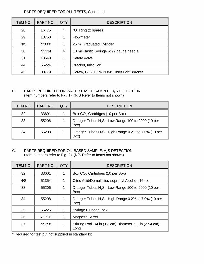
PARTS REQUIRED FOR ALL TESTS, Continued
ITEM NO. PART NO. QTY DESCRIPTION
28 L6475 4 "O" Ring (2 spares)
29 L8750 1 Flowmeter
N/S N3000 1 25 ml Graduated Cylinder
30 N3334 4 10 ml Plastic Syringe w/22 gauge needle
31 L3643 1 Safety Valve
44 55224 1 Bracket, Inlet Port
45 30779 1 Screw, 6-32 X 1/4 BHMS, Inlet Port Bracket
B. PARTS REQUIRED FOR WATER BASED SAMPLE, H2S DETECTION (Item numbers refer to Fig. 1) (N/S Refer to Items not shown)
ITEM NO. PART NO. QTY DESCRIPTION
32 33601 1 Box CO2 Cartridges (10 per Box)
33 55206 1 Draeger Tubes H2S - Low Range 100 to 2000 (10 per Box)
34 55208 1 Draeger Tubes H2S - High Range 0.2% to 7.0% (10 per Box)
C. PARTS REQUIRED FOR OIL BASED SAMPLE, H2S DETECTION (Item numbers refer to Fig. 2) (N/S Refer to Items not shown)
ITEM NO. PART NO. QTY DESCRIPTION
32 33601 1 Box CO2 Cartridges (10 per Box)
N/S 51354 1 Citric Acid/Demulsifier/Isopropyl Alcohol, 16 oz.
33 55206 1 Draeger Tubes H2S - Low Range 100 to 2000 (10 per Box)
34 55208 1 Draeger Tubes H2S - High Range 0.2% to 7.0% (10 per Box)
35 55225 1 Syringe Plunger Lock
36 N5251* 1 Magnetic Stirrer
37 N5258 1 Stirring Rod 1/4 in (.63 cm) Diameter X 1 in (2.54 cm) Long
* Required for test but not supplied in standard kit.

D. PARTS REQUIRED FOR WATER BASED SAMPLE, CO2 DETECTION (Item numbers refer to Fig. 3) (N/S Refer to Items not shown)
ITEM NO. PART NO. QTY DESCRIPTION
38 33602 1 Box N2O Cartridges (10 per Box)
39 55203 1 Draeger Tubes, CO2 Analysis (Scaled in PPM)
40 55211 3 Draeger Gas Bag, 1 liter (2 spares)
41 55212 1 Draeger Hand Vacuum Pump
42 55213 1 Straight Bore Stopcock
43 55216 1 Connector Tube, Plastic, 5/16 in (8mm) Diameter X 3 in (7.6 cm) Long
E. ACCESSORIES NOT SUPPLIED WITH GARRETT GAS TRAIN KIT
PART NO. DESCRIPTION
31700 Hose, 3 ft.
33513 1/8 NPT X Eastman Adapter
34005 Cylinder, N2 Size D
34265 Regulator Assembly for N2 Cylinder
64036 Hydrogen Sulfide Paper Disk (pkg. of 100)
N5251 Magnetic Stirrer
