g c 3.0 troubleshooting guide - lippert · pdf fileleveling jack (fig. 6) both have a ......
TRANSCRIPT

Rev: 01.30.2015 Page 1 Ground Control 3.0 Troubleshooting Guide
G����� C������ 3.0
TROUBLESHOOTING GUIDE
Rev: 01.30.2015 Page 2 Ground Control 3.0 Troubleshooting Guide
GROUND CONTROL 3.0 TROUBLESHOOTING GUIDE
TABLE OF CONTENTSIntroduction 3Components 3Operation 6Basic Jack Operation 6Auto Level 6Auto Level Sequence 7Hitch Recognition 7Homing Jacks 8Zero Point Calibration 8
Troubleshooting - Touch Pad 9Special Jack Error Codes 9Touch Pad Error Codes 94 - Point Wiring Diagram 116 - Point Wiring Diagram 12
Rev: 01.30.2015 Page 3 Ground Control 3.0 Troubleshooting Guide
GROUND CONTROL 3.0 TROUBLESHOOTING GUIDE
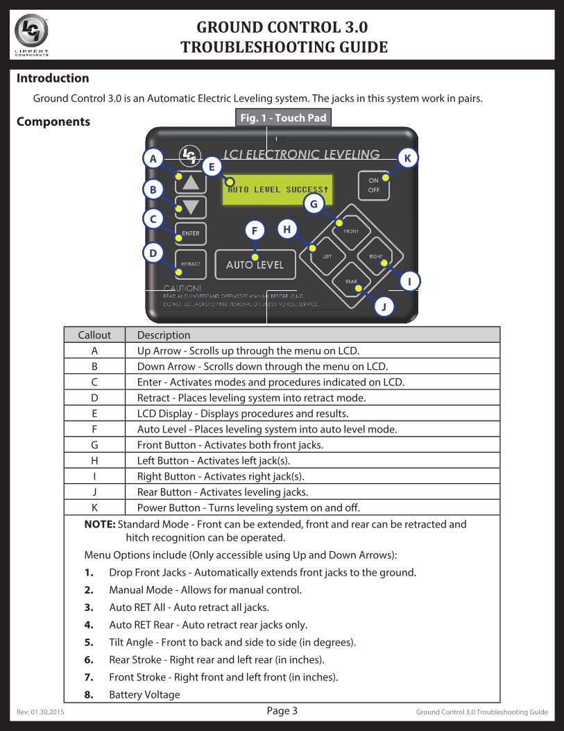
IntroductionGround Control 3.0 is an Automatic Electric Leveling system. The jacks in this system work in pairs.
Components
A
B
C
D
F
G
H
J
I
KE
Callout DescriptionA Up Arrow - Scrolls up through the menu on LCD.B Down Arrow - Scrolls down through the menu on LCD.C Enter - Activates modes and procedures indicated on LCD.D Retract - Places leveling system into retract mode.E LCD Display - Displays procedures and results.F Auto Level - Places leveling system into auto level mode.G Front Button - Activates both front jacks.H Left Button - Activates left jack(s).I Right Button - Activates right jack(s).J Rear Button - Activates leveling jacks.K Power Button - Turns leveling system on and off.
NOTE: Standard Mode - Front can be extended, front and rear can be retracted and hitch recognition can be operated.
Menu Options include (Only accessible using Up and Down Arrows):
1. Drop Front Jacks - Automatically extends front jacks to the ground.
2. Manual Mode - Allows for manual control.
3. Auto RET All - Auto retract all jacks.
4. Auto RET Rear - Auto retract rear jacks only.
5. Tilt Angle - Front to back and side to side (in degrees).
6. Rear Stroke - Right rear and left rear (in inches).
7. Front Stroke - Right front and left front (in inches).
8. Battery Voltage
Fig. 1 - Touch Pad
Rev: 01.30.2015 Page 4 Ground Control 3.0 Troubleshooting Guide
GROUND CONTROL 3.0 TROUBLESHOOTING GUIDE
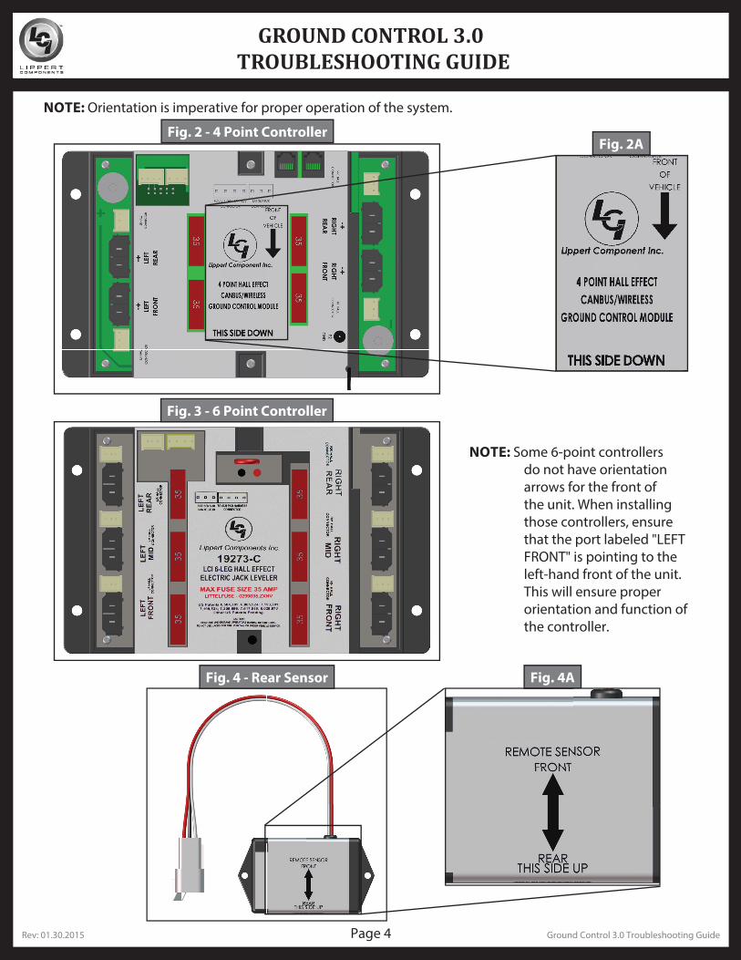
Fig. 2 - 4 Point ControllerFig. 2A
Fig. 4 - Rear Sensor Fig. 4A
NOTE: Orientation is imperative for proper operation of the system.
Fig. 3 - 6 Point Controller
NOTE: Some 6-point controllers do not have orientation arrows for the front of the unit. When installing those controllers, ensure that the port labeled "LEFT FRONT" is pointing to the left-hand front of the unit. This will ensure proper orientation and function of the controller.
Rev: 01.30.2015 Page 5 Ground Control 3.0 Troubleshooting Guide
GROUND CONTROL 3.0 TROUBLESHOOTING GUIDE
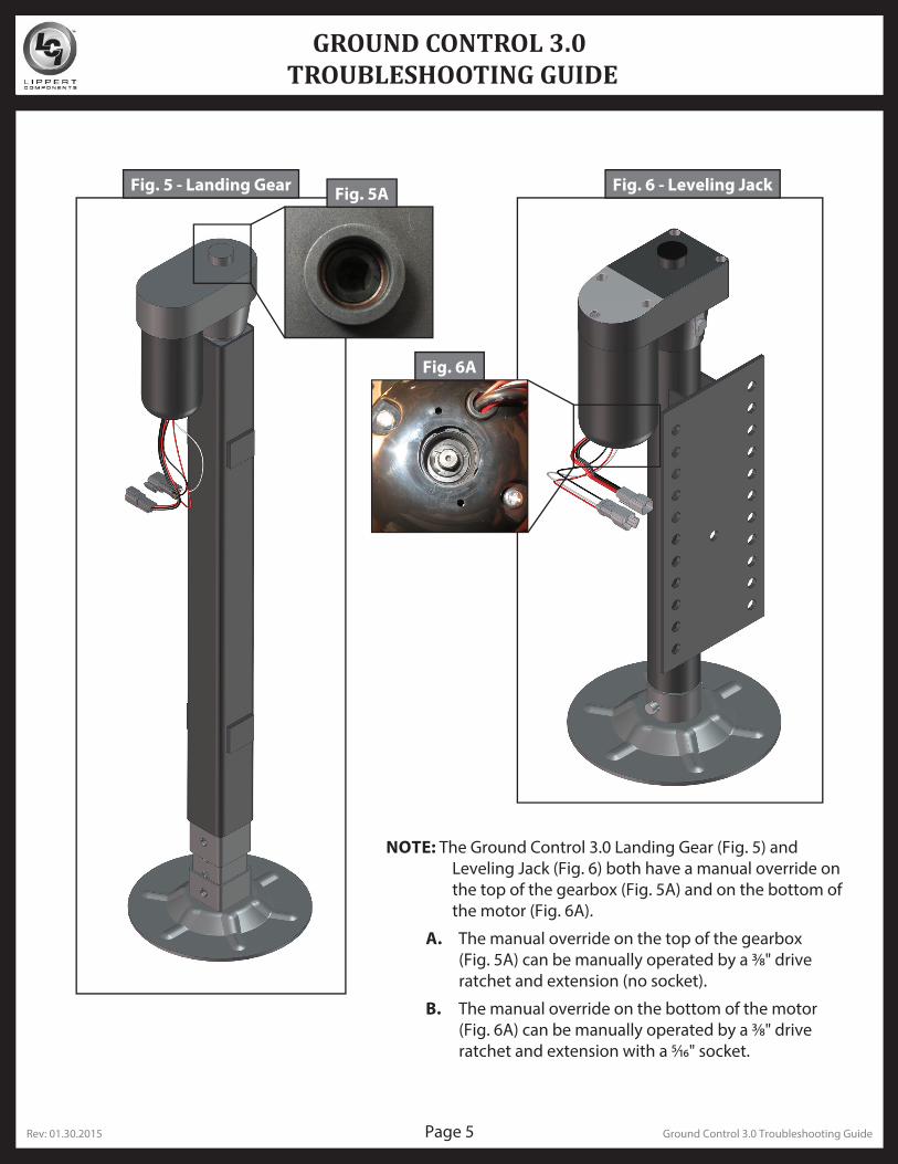
Fig. 5 - Landing Gear Fig. 6 - Leveling JackFig. 5A
Fig. 6A
NOTE: The Ground Control 3.0 Landing Gear (Fig. 5) and Leveling Jack (Fig. 6) both have a manual override on the top of the gearbox (Fig. 5A) and on the bottom of the motor (Fig. 6A).
A. The manual override on the top of the gearbox (Fig. 5A) can be manually operated by a 3⁄8" drive ratchet and extension (no socket).
B. The manual override on the bottom of the motor (Fig. 6A) can be manually operated by a 3⁄8" drive ratchet and extension with a 5⁄16" socket.
Rev: 01.30.2015 Page 6 Ground Control 3.0 Troubleshooting Guide
GROUND CONTROL 3.0 TROUBLESHOOTING GUIDE
OperationBasic Jack OperationLanding gear jacks can be operated any time the system is “ON”. By pushing the “FRONT” button (Fig. 1G), both front or landing gear jacks can be extended. By pushing either the "FRONT" and “LEFT” (Fig. 1H) or "FRONT" and “RIGHT” (Fig. 1I) buttons, the individual front jacks can be extended. If the touch pad is put in the retract mode, indicated by the orange illuminated LED next to the “RETRACT” button (Fig. 1D), the front jacks can be retracted together by pushing the “FRONT” button (Fig. 1G) or individually by pressing “LEFT” (Fig. 1H) or “RIGHT” (Fig. 1I) buttons, while simultaneously pressing the “FRONT” button (Fig. 1G).
NOTE: Middle jacks can only be operated in error mode. In order to engage middle jacks, press "LEFT" and "RIGHT" buttons simultaneously.
The rear jacks can only be extended when the touch pad is in the manual mode. Once system is in manual mode, pressing the “REAR” button (Fig. 1J) will extend both rear jacks at the same time. To extend individual rear jacks, press the “LEFT” (Fig. 1H) or “RIGHT” (Fig. 1I) buttons while simultaneously pressing the “REAR” button (Fig. 1J), depending on which jack needs to be operated. If the touch pad is put in the retract mode, indicated by the orange illuminated LED next to the “RETRACT” button (Fig. 1D), the rear jacks can be retracted together by pushing the “REAR” button (Fig. 1J) or individually by pressing either the “LEFT” (Fig. 1H) or “RIGHT” (Fig. 1I) buttons, while simultaneously pressing the “REAR” button (Fig. 1J).
NOTE: If the rear jacks will not operate individually using the method described above, but they operate properly when Auto Level is performed, the Twist Prevention Protection system has locked out the operation to prevent damage to the frame of the unit.
Auto Level
NOTE: Prior to unhitching from the tow vehicle, ensure unit is parked on a level surface and be sure to chock the tires of the unit.
1. After unhitching from tow vehicle, press Auto Level (Fig. 1F).
NOTE: Once the automatic leveling cycle has been started, it is important that there is no movement in the coach until the unit has completed the leveling process. Failure to remain still during the leveling cycle could have an effect on the performance of the leveling system.
NOTE: In order for hitch recognition feature to function, the auto level sequence MUST be started with the front of the unit above level.
Rev: 01.30.2015 Page 7 Ground Control 3.0 Troubleshooting Guide
GROUND CONTROL 3.0 TROUBLESHOOTING GUIDE
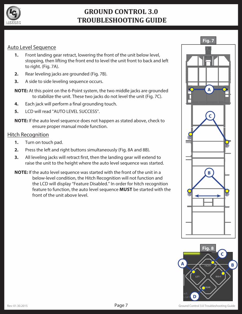
Auto Level Sequence1. Front landing gear retract, lowering the front of the unit below level,
stopping, then lifting the front end to level the unit front to back and left to right. (Fig. 7A).
2. Rear leveling jacks are grounded (Fig. 7B).
3. A side to side leveling sequence occurs.
NOTE: At this point on the 6-Point system, the two middle jacks are grounded to stabilize the unit. These two jacks do not level the unit (Fig. 7C).
4. Each jack will perform a final grounding touch.
5. LCD will read "AUTO LEVEL SUCCESS".
NOTE: If the auto level sequence does not happen as stated above, check to ensure proper manual mode function.
Hitch Recognition1. Turn on touch pad.
2. Press the left and right buttons simultaneously (Fig. 8A and 8B).
3. All leveling jacks will retract first, then the landing gear will extend to raise the unit to the height where the auto level sequence was started.
NOTE: If the auto level sequence was started with the front of the unit in a below-level condition, the Hitch Recognition will not function and the LCD will display “Feature Disabled.” In order for hitch recognition feature to function, the auto level sequence MUST be started with the front of the unit above level.
Fig. 7
Fig. 8
A B
A
B
C
D
C
Rev: 01.30.2015 Page 8 Ground Control 3.0 Troubleshooting Guide
GROUND CONTROL 3.0 TROUBLESHOOTING GUIDE
Homing Jacks1. Introduce an error - disconnect one of the hall effect sensor wires at the controller.
2. Attempt to operate the jack that is associated with the sensor wire that was disconnected. The touch pad screen will display an error for that jack.
3. Reconnect the hall effect sensor wire. Manually extend all jacks down a minimum of 6 inches.
4. Press and hold the retract button until all of the jacks begin to retract. The jacks will retract until they reach the hard current limit.
5. The jacks are now “homed.”
NOTE: If the jacks do not retract, an error should display on the touch pad screen. This is typically caused by wiring interruption.
NOTE: In order to "home" jacks, middle jacks must also be extended. Refer to Basic Jack Operation for middle jack operation.
Zero Point CalibrationThe “Zero Point” is the programmed point that the unit will return to each time the Auto Level feature is used. The “Zero Point” must be programmed prior to using the Auto Level feature to ensure the proper operation of the system.
NOTE: Prior to starting this procedure, double check all connections on the controller, jacks, and touch pad.
1. Manually run the jacks to level the unit. This is best achieved by placing a level in the center of the unit and leveling it both front to back and then side to side. (See “Basic Jack Operation” for instructions on how to manually operate the system).
2. Once the unit is level, turn off the touch pad.
3. With the touch pad off, press and release the “FRONT” button (Fig. 1G) five (5) times and then press and release the “REAR” button (Fig. 1J) five (5) times.
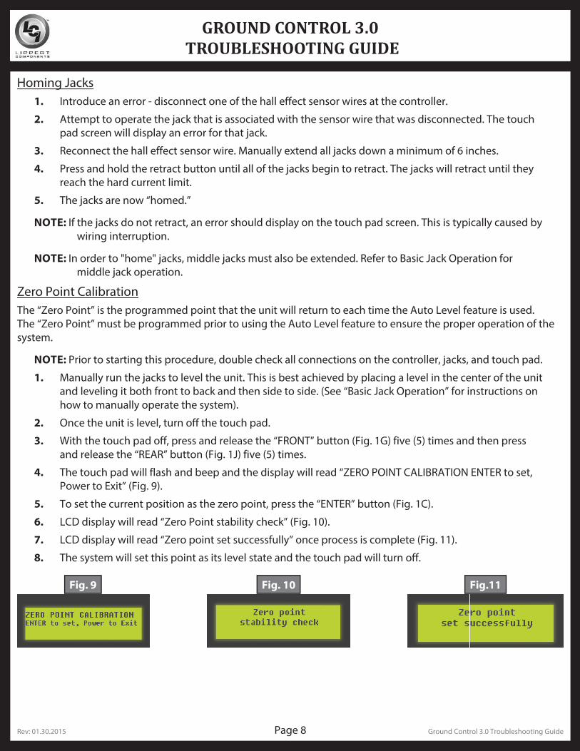
4. The touch pad will flash and beep and the display will read “ZERO POINT CALIBRATION ENTER to set, Power to Exit” (Fig. 9).
5. To set the current position as the zero point, press the “ENTER” button (Fig. 1C).
6. LCD display will read “Zero Point stability check” (Fig. 10).
7. LCD display will read “Zero point set successfully” once process is complete (Fig. 11).
8. The system will set this point as its level state and the touch pad will turn off.
Fig. 9 Fig. 10 Fig.11
Rev: 01.30.2015 Page 9 Ground Control 3.0 Troubleshooting Guide
GROUND CONTROL 3.0 TROUBLESHOOTING GUIDE
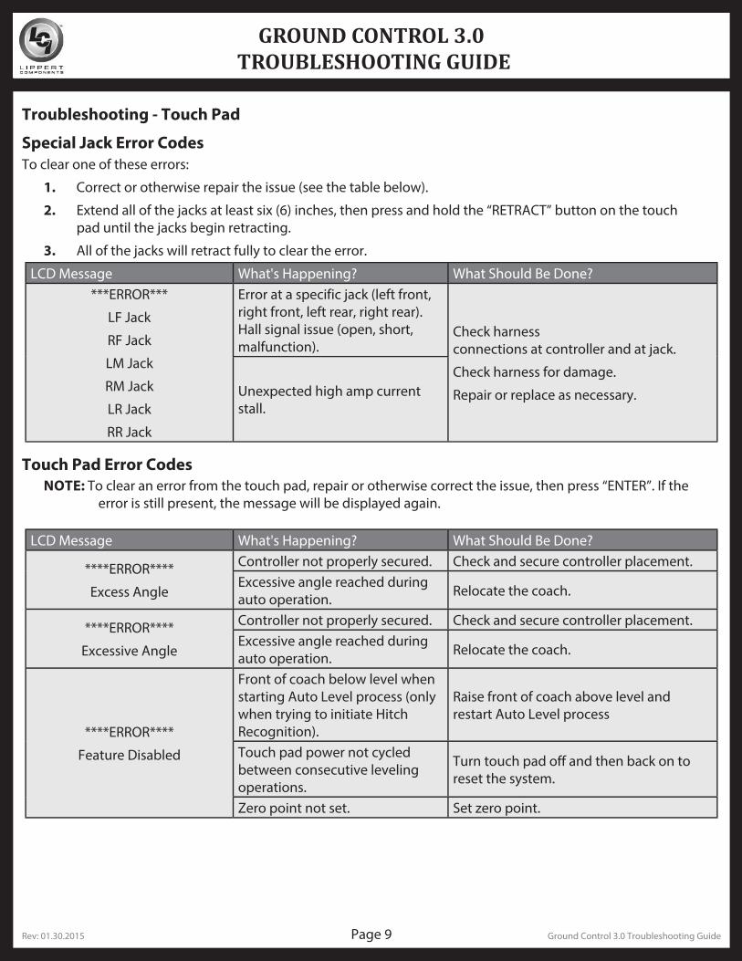
Troubleshooting - Touch Pad
Touch Pad Error CodesNOTE: To clear an error from the touch pad, repair or otherwise correct the issue, then press “ENTER”. If the
error is still present, the message will be displayed again.
Special Jack Error CodesTo clear one of these errors:
1. Correct or otherwise repair the issue (see the table below).
2. Extend all of the jacks at least six (6) inches, then press and hold the “RETRACT” button on the touch pad until the jacks begin retracting.
3. All of the jacks will retract fully to clear the error.
LCD Message What's Happening? What Should Be Done?***ERROR***
LF Jack
RF Jack
LM Jack
RM Jack
LR Jack
RR Jack
Error at a specific jack (left front, right front, left rear, right rear). Hall signal issue (open, short, malfunction).
Check harness connections at controller and at jack.
Check harness for damage.
Repair or replace as necessary.Unexpected high amp current stall.
LCD Message What's Happening? What Should Be Done?
****ERROR****
Excess Angle
Controller not properly secured. Check and secure controller placement.Excessive angle reached during auto operation. Relocate the coach.
****ERROR****
Excessive Angle
Controller not properly secured. Check and secure controller placement.Excessive angle reached during auto operation. Relocate the coach.
****ERROR****
Feature Disabled
Front of coach below level when starting Auto Level process (only when trying to initiate Hitch Recognition).
Raise front of coach above level and restart Auto Level process
Touch pad power not cycled between consecutive leveling operations.
Turn touch pad off and then back on to reset the system.
Zero point not set. Set zero point.
Rev: 01.30.2015 Page 10 Ground Control 3.0 Troubleshooting Guide
GROUND CONTROL 3.0 TROUBLESHOOTING GUIDE
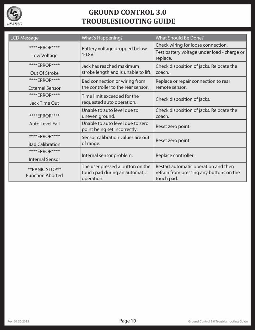
LCD Message What's Happening? What Should Be Done?
****ERROR****
Low VoltageBattery voltage dropped below 10.8V.
Check wiring for loose connection.Test battery voltage under load - charge or replace.
****ERROR****
Out Of StrokeJack has reached maximum stroke length and is unable to lift.
Check disposition of jacks. Relocate the coach.
****ERROR****
External SensorBad connection or wiring from the controller to the rear sensor.
Replace or repair connection to rear remote sensor.
****ERROR****
Jack Time OutTime limit exceeded for the requested auto operation. Check disposition of jacks.
****ERROR****
Auto Level Fail
Unable to auto level due to uneven ground.
Check disposition of jacks. Relocate the coach.
Unable to auto level due to zero point being set incorrectly. Reset zero point.
****ERROR****
Bad CalibrationSensor calibration values are out of range. Reset zero point.
****ERROR****
Internal SensorInternal sensor problem. Replace controller.
**PANIC STOP**Function Aborted
The user pressed a button on the touch pad during an automatic operation.
Restart automatic operation and then refrain from pressing any buttons on the touch pad.
Rev: 01.30.2015 Page 11 Ground Control 3.0 Troubleshooting Guide
GROUND CONTROL 3.0 TROUBLESHOOTING GUIDE
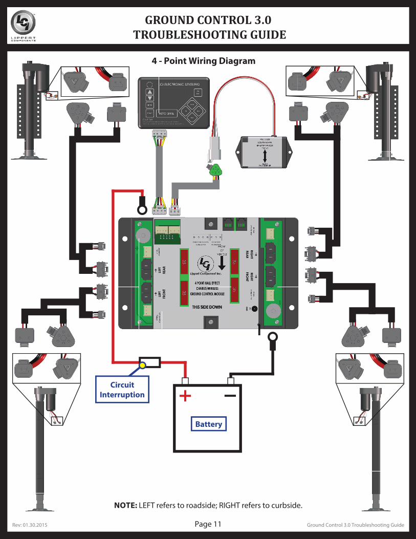
4 - Point Wiring Diagram
Circuit Interruption
Battery
NOTE: LEFT refers to roadside; RIGHT refers to curbside.
Rev: 01.30.2015 Page 12 Ground Control 3.0 Troubleshooting Guide
GROUND CONTROL 3.0 TROUBLESHOOTING GUIDE
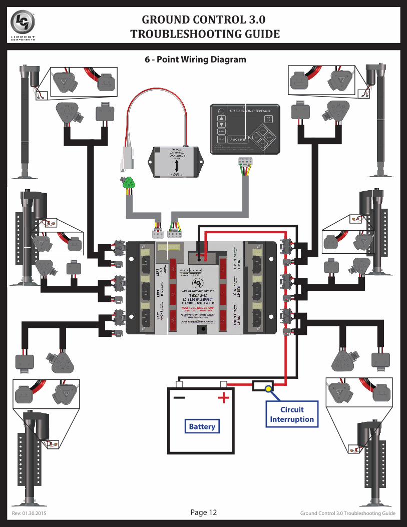
6 - Point Wiring Diagram
Battery
Circuit Interruption

Rev: 01.30.2015 Page 13 Ground Control 3.0 Troubleshooting Guide
All information contained within may be distributed as a full document only, unless otherwise permitted by explicit consent of Lippert Components Inc. to distribute individual parts.
All information contained within is subject to change without notice. New editions will be posted on www.lci1.com and can be downloaded for free. Information contained within is considered factual until made obsolete
by a *NEW* revision.
Please recycle all obsolete materials.
For all concerns or questions, please contact
Lippert Components, Inc.
Ph: (574) 537-8900 Web: www.lci1.com Email: [email protected]