d. leveling - u.s. geological survey publications · pdf fileleveling 119 for topographic...
TRANSCRIPT

D. LEVELING
Compiled by E. M. DOUGLAS
GENERAL FEATURES
RESPONSIBILITY
The following instructions are formulated to assist the levelman in obtaining accurate results. Before he undertakes any work for the Geological Survey he must familiarize himself with these instruc tions in every detail, for he will be held strictly accountable for any deviation from them and personally responsible for the proper execution of his work. In order to be sure that the instructions have been received and are understood, a postal-card acknowledgment is required from each levelman at the beginning of his season's field work. He must understand that elevations of bench marks are pub lished for the use of engineers outside of the Geological Survey and are sometimes used for large engineering projects. They must be reliable, or the Geological Survey may be subject to severe criticism. The proper contouring of topographic maps depends wholly on the character and the accuracy of the vertical control. The levelman must therefore realize the vital importance of his work and must give to it from the start such care and attention as will insure its thorough accuracy.
Levelmen working in the same area with topographers should so arrange their work as to satisfy in every way possible the requests and needs of the topographers in respect to priority and sequence of the work. The topographer in charge of mapping an area should be certain that a copy of these instructions is in the hands of every levelman in the area and that the instructions are understood by the levelmen. In the technical details of execution of his work, how ever, the levelman is directly responsible to the Washington office.
When a levelman is sent to any area for work he will be furnished with special instructions and all necessary data pertaining to that area. In "an area where his work has been preceded by transit traverse he must follow the traverse route if practicable, but in any area he must utilize all permanent traverse marks as bench marks, which must be turning points in the line, and he must tie his work to any permanent or substantial marks of other organizations that he may find along the line, making them turning points also.
117

118 TOPOGRAPHIC INSTRUCTIONS OP GEOLOGICAL SURVEY
TYING NEW WORK TO OLD
Every bench mark from which new work is to be started must be checked by leveling to an adjacent established bench mark before the work proceeds. If the closure error between those two bench marks is not within the limits allowed, the section should be releveled, and if the closure is still out of limits the line must be continued until two old bench marks are found between which the closure comes within the limits. The initial elevation of the new work must be derived from one of two bench marks that agree. For the end of the ' line a tie to one bench mark will be sufficient, provided the closure is within the limits; otherwise the line must be run to a second or third mark. \
A complete description must be given of all previously established bench marks to which new work is tied. Whether beginning or ending a new line, or touching older lines in any part of the new work, these junction bench marks must be so fully described that there can be no uncertainty as to which marks have been used. If the results of the older work have been published, give bulletin num ber and page. If the bench mark has been recently established give page references to the field book where it has previously been re corded or show from what source its data have been obtained. Give in parentheses the old elevation. Make a note describing the condi tion of the old mark and stating whether it shows signs of having been disturbed.
When a levelman finds a previously established permanent bench mark broken or in bad condition he must replace it or reset it. If a new tablet is used it should be stamped like the one replaced, except that if the elevation has been adjusted the new figure should be used, and a full report, including change in elevation, if any, should be sent promptly to the Washington office.
If the bench mark is also a transit-traverse mark and a horizontal change in its location is found necessary, the magnetic bearing must be taken and the distance from the original position accurately meas ured with steel tape. The descriptions of both the old and the new marks, their elevations, and a sketch showing their positions must be promptly transmitted to the Washington office. If the tablet previously set is incorrectly stamped the erroneous figures should be carefully cut out with a chisel and the correct figures stamped in their place and verified. This action, together with a description and a sketch of the bench mark, must be promptly reported.
DISTRIBUTION OF VERTICAL CONTROL
The act of Congress providing for the sundry civil expenses of the Government for the fiscal year 1896-97 contains the following para graph :

LEVELING 119
For topographic surveys in various portions of the United States * * * Provided, That hereafter in such surveys west of the ninety-fifth meridian elevations above a base-level located in each area under survey shall be deter mined and marked on the ground by iron or stone posts or permanent bench marks, at least two such posts or bench marks to be established in each town ship or equivalent area, except in the forest-clad and mountainous areas, where at least one shall be established, and these shall be placed, whenever practicable, near the township corners of the public-land surveys; and in the areas east of the ninety-fifth meridian at least one such post or bench mark shall be similarly established in each area equivalent to the area of a township of the public-land survey.
The most advantageous locations of level lines for a 15-minute quadrangle are near the borders of the quadrangle and from east to west through the center, the same arrangement as is required for transit-traverse lines. If additional leveling control is needed by the topographer the lines should be run by the levelman as a good grade of fourth-order levels, but without setting any per manent bench marks. Permanent bench marks should not be estab lished by means of any level lines of a grade less accurate than that described on page 130 as " third order."
PERMANENT BENCH MARKS
Distribution. Permanent bench marks should be placed along level lines at intervals of approximately 3 miles, unless the level man is otherwise instructed, and the distance between bench marks should nowhere exceed 4 miles. They should be established if practicable at township corners of the public-land surveys; near all large lakes and reservoirs; at crossings of the larger streams and divides; in the vicinity of active mines; and in every city, town, or large village traversed. In county seats and cities that have a popu lation of 10,000 or more two permanent bench marks, some distance apart, must be established. Along public highways and railroads bench marks should be located where practicable at road junctions and crossings.
Best locations. Permanent bench marks should be so located that they will not be liable to injury or disturbance, yet they should be so prominent as to be easily found. Along a railroad or high way they should be placed, if practicable, outside the right of way but close to it. If such a location is impracticable and they are lo cated within the right of way care should be taken for their preser vation in the event of future changes in road location. Bench-mark posts must not be set close to trees, telegraph poles, or fence posts, or in front of gateways. They should not be set in swampy soil.
Tablets must not be set in boulders within the right of way of any well-established highway, or in any part of a bridge structure.

120 TOPOGRAPHIC INSTRUCTIONS OF GEOLOGICAL SURVEY
Permission* of landowner. Before a bench mark is set on private property permission should be obtained from the owner or agent, but if this is impracticable Written notification, explaining the neces sity for the mark should immediately be sent to him.
Bench marks on Federal buildings. If the custodian of a Federal building objects to the placing of a bench-mark tablet in the build ing, the exhibition of the following copy of a letter from the Assist ant Secretary of the Treasury should induce him to give the neces sary permit.
TREASURY DEPARTMENT, Washington, December %2, 1920.
The honorable the SECRETARY OF THE INTERIOR.SIR: By direction of the Secretary, the receipt is acknowledged of a letter
from the First Assistant Secretary of the Interior, dated December 20, 1920, requesting that permission be granted to the officers of the United States Geological Survey of your department to place on the Federal buildings under the control of this department small inscribed metal tablets, which are to be used as bench marks in connection with the system of leveling, the custodians of the buildings to designate where the tablets are to be placed.
No objection will be interposed by this department to the placing of such tablets on the various Federal buildings as desired, and this letter or a copy thereof, upon its presentation to the custodian of a Federal building, is to be considered by him as his authority for permitting the placing of one of the tablets on the building in his custody.
(Signed) J. H. MOYLE,Assistant Secretary.
Form, materials, and construction. The tablets that form perma nent bench marks are fastened with cement in large boulders, in solid rock in place, in permanent masonary structures, or in the top of concrete posts. (See pi. 4.) The tablet should be counter sunk so that its lettered surface is flush with the surface of the rock or concrete in which it is set.
Portland cement in air-tight cans is supplied from the Washington office for use in setting tablets in rock or in masonary already in place. If good clean sand is available it can be mixed with the dry cement in equal parts. The drill hole for the tablet must be well cleaned and wet. The cement and sand, or cement alone if pure sand can not be conveniently procured, should then be thoroughly mixed with water to a thick paste, which should be packed into the drill hole. The stem of the tablet should then be pushed into the hole, when the excess cement will be forced out and the cement will fill completely the space under the tablet. In order that the cement may set well, it should be kept damp and protected from the sun for at least a day, and for 12 hours it should not be allowed to freeze. Damp earth or a piece of sacking will probably be sufficient pro tection. If a tablet is set in a vertical wall a prop may be neces sary to hold it in place until the cement sets.

LEVELING 121
Suitable concrete posts may be made by contract in a town where materials are available, or they may be made by the levelman at the place where they are needed. They should generally be long enough to extend below frost line, and may be square or round in section; their sides should taper, and the top should be at least 6 inches and the bottom about 12 inches across. The post should be reinforced by three or four pieces of heavy galvanized-iron wire. The top of the post should not project more than 6 inches above the natural surface of the ground. The concrete should consist of 1 part cement. 2 parts sand free from loam or clay, and 3 parts coarse gravel or broken stone. The upper 12 inches of the post should be made of a mixture of 2 parts sand to 1 part cement, without any gravel or stone, and the tablet should be put in position in the top of the post when the post is made. The mixture should be made up with just sufficient water to moisten it thoroughly, and it must be well tamped in the mold. An excess of water is harmful. The post, when completed, should be sheltered from the sun for several days and wetted frequently if practicable.
The point of elevation on all ^tablets, whether set vertically or horizontally, is the intersection of the cross lines inside of the triangle.
Reference marks. A reference mark, which shall be made a turn ing point in the line or be on a checked spur line, must be established near every permanent bench mark. Reference marks should conform to the instructions given for supplementary bench marks and should be described with equal care.
Establishing marks after line is i^un. If conditions make it neces sary to leave the setting of a permanent bench mark till after the line is run, two temporary bench marks (both of them turning points in the line) must be left near the point selected, one of which is to be a reference mark. The elevation of the permanent bench mark must be determined by readings on both of the temporary marks from two different set-ups. A single " side shot" is never sufficient in establishing the elevation of a bench mark.
Pavnted elevations. The letters " U. S. B. M.," together with the determined elevation to tenths of a foot, arranged when practicable thus:
U.S.[figures]
B. M.
must be neatly painted in letters and figures 4 inches high on some convenient object near every permanent bench mark in order to insure its being readily found by the topographer or traverseman. When no suitable object is found on which to paint, a mound of rock or
122 TOPOGRAPHIC INSTRUCTIONS OF GEOLOGICAL SURVEY
earth large enough to attract attention must be left. The painted elevations must be in no way objectionable or offensive to the owners of property or to travelers. Prominent trees along public highways must not be defaced by blazing except as a last resort.
Sta/mping. To facilitate the identification of permanent bench marks, an individual letter will be assigned by the chief of division to each levelman, which he must stamp on all tablets set by him. He will also stamp on each permanent bench mark a number, which will be serial for all tablets set by him in any one State during one sea son, and this number must be followed by figures showing the year in which the work was done. For example, " C-10-1920 " means that the line was run by levelman C and that it was the tenth perma nent bench mark set by him in that State in 1920. These letters and figures will be stamped beneath the space left for the figures showing the elevation and must be stamped before the bench mark is set; they should be in two lines, the figures for the year on the second line. If the mark is both a transit-traverse mark and a bench mark, the control man who first establishes the mark should stamp it with his letter and serial number. The second man should not add his own stamping to this but should use the first man's let ter and number to identify the mark.
Figures of elevation must not be stamped on metal bench marks until the level lines have been adjusted and the final elevations sup plied by the Washington office. Usually the elevations can not be stamped until the field season after the marks are set, and the stamp ing may be done by a different engineer from the one who set the marks.
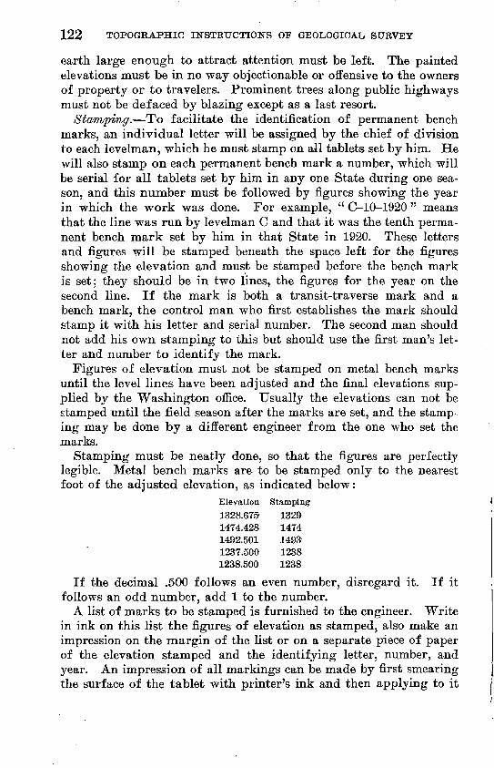
Stamping must be neatly done, so that the figures are perfectly legible. Metal bench marks are to be stamped only to the nearest foot of the adjusted elevation, as indicated below:
Elevation Stamping
1328.675 13291474.428 14741492.501 14931237.500 12381238.500 1238
If the decimal .500 follows an even number, disregard it. If it- follows an odd number, add 1 to the number.
A list of marks to be stamped is furnished to the engineer. Write in ink on this list the figures of elevation as stamped, also make an impression on the margin of the list or on a separate piece of paper of the elevation stamped and the identifying letter, number, and year. An impression of all markings can be made by first smearing the surface of the tablet with printer's ink and then applying to it

LEVELING 123
and rubbing down a piece of white paper, or by holding the paper firmly on the tablet and rubbing over it with a soft lead pencil.
If a tablet is wrongly stamped, as soon as the error is discovered cut out with the small cold chisel supplied the erroneous figures and restamp the correct ones. If the erroneous figures have been re ported to the Washington office the correction should also be reported.
The list should be returned to the Washington office as soon as the stamping is completed.
SUPPLEMENTARY BENCH MARKS
As descriptions of supplementary bench marks are published in level bulletins and their elevations are given on topographic maps, careful attention must be given to their character and location, in order that they may be made as permanent as possible and easily accessible. They should be placed where they are least likely to be disturbed and yet can readily be found from the descriptions.
Supplementary bench marks must always be turning points in the main line and should be set at intervals of half a mile to a mile on all lines. On railroads and highways they should be set at the principal crossings, crossroads, and road intersections. They may consist of well-defined chiseled marks, preferably forming a square, on solid rock in place or on permanent structures of concrete or stone, or bolt heads surrounded by painted rings on steel structures, or copper nails with lettered washers in exposed roots of suitable trees. No other form or material less substantial than those above specified should be used for supplementary bench marks.
The elevations of all supplementary bench marks as at first deter mined by the levelman must be painted to tenths of a foot on some convenient object near by, as explained on page 124.
USEFUL ELEVATIONS
The levelman should bear in mind that his work is not an end in itself but a preparation for the work of others and that the accuracy with which his circuits check, though of paramount importance, is not the only feature that determines its usefulness.
Besides the elevations of the permanent and supplementary bench marks a number of other elevations are required for the use of the topographer, and they should be distributed with a special view to their usefulness in topographic mapping. For instance, an eleva tion painted on a summit will be of great value to the topographer, whereas one painted below it, simply because a turning point can more easily be made there, is of far less value.
The points for which elevations are particularly useful are the tops of rails at railroad stations, junctions, sidings, and crossings;
58515° 28 9

124 TOPOGRAPHIC INSTRUCTIONS OF GEOLOGICAL SURVEY
the center of the road at crossroads, road forks, bends, and summits; points near schoolhouses and other public buildings, lone houses, active mines and quarries, and oil, gas, and artesian wells; the water surface of streams under bridges, at stream crossings, and above and below dams; and the water surface of lakes and reser voirs. The date and hour when the measurement of a water-surface elevation was made should be recorded.
The number of these elevations should differ according to the nature of the country and the contour interval used for the map. Thus, in rugged regions mapped with 50 or 100 foot contour inter vals relatively few elevations are required, but in areas of gently rolling surface they should be more numerous.
Elevations should be determined to the nearest tenth of a foot for such of these points as are of a definite nature for example, the top of a rail or a bridge floor.
Ground elevations (to the nearest foot only) should be neatly painted in conspicuous places along the sides of roads and on fences, telephone poles, trees, or rocks. If practicable, all such marks along a road should be placed on the same side of the road. On a bridge the elevation of the floor should be painted on the railing or truss immediately above it, not on the floor itself.
NOTES AND RECORDS
The fly leaf of every field book should be filled in before any other records are put in the book. Instrument and rod numbers must be given.
Notes should be kept as neatly as possible, and all figures should be clear and plain, so that there can be no possibility of misreading them. Ink or hard pencil may be used. Do not erase an incorrect figure or record, but draw a single line through it, and write the correct entry above it. Do not use separate loose sheets of paper for recording notes; all records must be set down directly in the books, so that there can be no possibility of losing a part of them.
The description of a bench mark should begin directly opposite the entry indicating elevation. Notes should not be crowded, and if two descriptions occur close together, the records for the second mark should be started enough farther down on the left-hand page to clear the description of the first mark.
There are a number of items that should be recorded in addition to the rod readings and elevations. Weather conditions and tempera ture, details of rod and instrument tests, brief statements of unusual incidents that may affect the results, page cross references at junction points, and other such details form a necessary and important part of the records and should be written on the right-hand page of the

LEVELING 125
notebook, commencing opposite the entry for the point in the line to which they apply. Every page heading should be filled in with the date and a brief description of the line.
In short, the levelman should remember that his notes are made for the purpose of transmitting information to the office and there fore should be in such shape as to be clearly understandable not only by himself but by others.
Forward the records to the Washington office by registered mail. Field books and bench-mark books should be sent in different pack ages on different days, so that if one package is lost the other may furnish the data for the line. It is very unlikely that both packages would go astray. A letter or card should also be sent, stating that the books have been mailed.
DESCRIPTIONS OF BENCH MARKS AND USEFUL ELEVATIONS
Complete descriptions of all bench marks and useful elevations must be entered in the field notebook and should be copied in the description book (9-916) at the end of each day's work. A com prehensive sketch should be made in both notebook and description book showmg the correct position of each bench mark in rela tion to near-by objects, such as streets, roads, and railroads, and indicating by arrows the direction of the line that is being run and the true north. Such a sketch must accompany the description of every permanent bench mark. Sample pages of the field notebook and bench-mark description book are given on pages 135 and 136.
Descriptions are of the greatest importance in all level records, and the levelman must therefore take particular care to make them comprehensive, concise, clear, neat, and legible and to arrange them in proper form for publication. The items of the descriptions should be written in the following order:
1. Name of the nearest post office, town, village, or other well- Imown locality, with direction and distance from it to the bench mark, in miles and tenths; or the township, range, and section in which the bench mark stands, with direction and distance from the nearest corner. When a new reference point is cited in the description give the distance to the former point as well as to the new one, thus affording data for total mileage.
2. Position with reference to buildings, bridges, mileposts, and streets or road corners; if along a road, state on which side. Give compass directions; do not use " right" or " left."
3. Description of object on which the bench mark is placed, such as boulder, tree, or concrete post.
Items 2 and 3 should be written in direct (uninverted) form. Items 1, 2, and 3 answer the question "Where?" and should be followed by item 4, which answers the question "What?"
126 TOPOGRAPHIC INSTRUCTIONS OF GEOLOGICAL SURVEY
4. Nature of the bench mark tablet, chisel mark on rock, copper nail with washer, iron pipe, etc. and how marked or stamped; the object on which the figures of elevation are painted should also be named.
Old bench marks to which the line is tied must be fully described and shown on a sketch, and the old elevation and source of informa tion must be given.
If a previously set transit-traverse mark is used for a bench mark, the description must be the same as the traverseman's unless that is found to be erroneous; in that event a correct description must be entered in the description book, and a copy sent to the Washington office.
The levelman who sets a permanent bench mark should make a pencil copy of his description on a loose sheet of paper to transmit to the traverseman if one follows. This should be done each day. so that the set is up to date when the line is finished.
Descriptions should be written in the order in which the bench marks occur along th© line. If standard bench marks are not estab lished when the line is first run, spaces should be reserved for them in their proper order in both the field notebook and the description book. A brief description of the line should be given as a page heading, and when the direction of the line is changed the distance and direction froln the reference point along the route of the line should be given, not the air-line distance and direction. For ex ample, if the line runs in a general easterly direction for 6 miles from the reference point and then changes to a northerly direction, a bench mark set 3 miles beyond the bend should not be described as " about 7 miles northeast of" the reference point but as " 6 miles east, thence 3 miles north from."
If any correction is made to the field-book elevations when they are copied into the description book, a full explanation should be written in the description book, including the data warranting the change.
A neat and legible diagram of all lines and circuits must be "made on a page near the back of the description book. Boundaries of quadrangles should be shown, and if the area is covered by public- land surveys the position of each line with reference to township and section lines should also be shown. The direction in which each line was run must be indicated by arrowheads placed on the line, and the number of the page on which the record was made must be placed at the beginning and end of each circuit and line; the location of all permanent bench marks must be indicated by crosses; and all towns and villages and the crossings of the larger streams must be shown. The records in the description* book are incomplete without this diagram.

LEVELING 127
CLOSURES AND BEBUNITING
Formulas are given for the limits of error and closures on the different types of lines hereinafter described. If a circuit fails to close within the specified limits, and if the levelman is in doubt what to do, he should immediately notify the Washington office, giving details of the line, descriptions of the initial and final bench marks, his rod numbers and tests, and any other information that may en able the office to verify data regarding older lines or to arrive in any way at an explanation of the excessive closure. Rod error is a common cause of failure of field results to close. Meanwhile, if additional lines that will intersect the line of error are conteniplated, they should be run by the levelman before he attempts any releveling over the erroneous line. These intersecting lines may show which part of the erroneous line is weak, and that part should then be investigated. If no explanation for the excessive closure can be found either in the office or in the field, the weak link or line should be rerun. This work should be done by a method as accurate as that by which the line was run at first, but in the opposite direction. If the line to be rerun is of the second order and has thus already been run twice, a single additional running, with the same care and re finements as in the original work, will suffice if it checks one of the two former lines. If the line is long it should preferably be rerun by a different levelman. Complete details of all rerunning should appear in the bench-mark description book.
When there is a large discrepancy between two runnings of any section of a line, a third running of the section is required in order to prove whether it is the first or the second running that is in error. If the third running agrees within the permissible limit with one of the other two their mean shall be used to carry forward the ele vation, the discordant one of the three being eliminated.
For example, suppose a circuit from A to B, with seven^jnter- rnediate bench marks, closed 1 foot out of limits. Begin at B and rerun back toward A to locate the error. Between bench marks B, 7, 6, and 5 the new line checks with the old, but between bench marks 5 and 4 a divergence between the two lines is found which is nearly equal to the closure error. Continue the line, however, to another bench mark (3) to verify this divergence. When it has been verified go back and rerun the line in either direction between bench marks 4 and 5, where the large divergence occurred. If a large discrepancy is found on rerunning a line between any two bench marks, that part of the line must be run a third time to dis cover which running was in error and to obtain two records that are in close agreement.

128 TOPOGRAPHIC INSTRUCTIONS OF GEOLOGICAL SURVEY
If as the rerunning progresses no error approaching the allowable closure limits is found between any two bench marks but the di vergence between the new and old lines continues, the error is shown to be cumulative, and in that case the rerunning must be continued to the end of the circuit or loop. If the closure is then satisfactory no third running of such a line is necessary. Before releveling any part of a large circuit on account of a large closure error, it is best to run a cross line if the additional bench marks will be useful or the probable amount of releveling thereby be reduced. This will localize the error in a smaller circuit.
Every effort should be made to have all lines closed satisfactorily before the leveling party leaves the locality, as faulty lines may prevent the adjustment and publication of the work. Lines may fail to close on account of error of two kinds gross errors and slight inaccuracies that accumulate through the line. Methods of minimiz ing the cumulative errors are discussed in the detailed instructions for the different kinds of work (pp. 131-133). Gross errors are usually due to carelessness, but occasionally even the most careful and pains taking man may make such an error. Failure to close a line may perhaps be due to no fault of the levelman. Sometimes the start ing or ending elevations may be incorrect, or there may be other understandable causes for the failure. In any case, if the levelman has been conscientious, painstaking, and careful, he need feel no embarrassment in occasionally failing to close a line and in record ing the circumstances fully in his books. Field notes should not be erased or altered, even to effect neatness in the books. Alteration to disguise or conceal an error or falsifying the records in any man ner is evidence of fraud and of course will not be tolerated. To avoid all question, therefore, it is best never to make an erasure of any sort in a field book, as any evidence of such a change will im mediately arouse suspicion when the notes reach the computer.
CARE OF INSTRUMENTS
Responsibility for damage. The effectiveness of instruments may be maintained by proper care in handling and transportation. This care is highly necessary} and everyone who is intrusted with instru ments is expected to see that they receive such care and protection that when returned to the custodian they will be in fit condition for further use. Damage or injury to leveling instruments is often the result of carelessness or negligence of the levelman or the rod- man. When evidence of such carelessness is discovered any expense incurred for repairs will be charged to the person who is fesponsible.
Level. When the level is not in use it should be kept in its wooden case, with the top fastened; that is the only way to insure it against being tampered with or knocked over.

U. S. GEOLOGICAL SURVEY BULLETIN 788 PLATE 7
INSTRUMENTS USED IN LEVELING
a. Wye level; &, New York level rod; c, prism level; dt yard rod

LEVELING 129
When the level is being transported to and from work in the field it should not be subjected to bumps or jars from riding unprotected on the floor of the conveyance. The safest way to carry it is in the lap, but if it is carried in its case the box should rest on a padded support. It should not be unnecessarily exposed to damp or rainy weather and must be kept in a dry place at night.
When the level is shipped by express it must be securely packed in its case with paper to protect it from jarring or its parts from shaking loose. Old newspaper makes excellent packing; excelsior or hay must not be used for this purpose. The wooden case con taining the level must be packed inside another box.
Rods. It is very important, particularly for areas where differ ences of elevation are considerable, that an accurate value for the length of the leveling rod be determined not only from tests by the Bureau of Standards but also from field tests by the levelman. At the beginning of each field season and at least every two weeks thereafter the levelman should make several measurements of each leveling rod he is using, with an invar test tape or a tested steel tape kept for that purpose, and record in proper order in his note book the mean of the result to thousandths of a foot for each gradu ation tested. State definitely the length of the rod interval tested, and give the rod number and test tape number. The tape should be held as nearly as possible at the tension for which it is tested, which should be 10 or 15 pounds. If an ordinary steel tape is used, special attention must be given to the reading and recording of the temperature. The comparisons should be made under the same conditions as those prevailing when the rod is in use. As invar strips are easily damaged by bending or by coiling too tightly, they must be handled carefully. Corrections for rod error need not be made in the field except in a rough way when needed to check circuit closures.
A levelman is responsible for the safety of the rod; he must see that the rodman takes proper care in handling and transporting it in the field. Particular care must be exercised not to expose the face of the rod to anything that may deface or mar it. The face of the rod must not be laid on the ground nor exposed unnecessarily to the weather. When not in use the rod must be kept in its canvas cover, and it must be stored in a dry place at night. When it is being transported to and from work it must be carried in its case and must be fully protected from rubbing or blows. When a ISTew York rod is shipped by express it should be either packed in a box or fastened to a board extending 2 inches beyond each end. The target should not be removed from the rod but should be fastened securely to a flat board and protected with hay or excelsior.
130 TOPOGRAPHIC INSTRUCTIONS OF GEOLOGICAL SURVEY
If the rod is not shipped in a box its face should be thoroughly protected and the entire rod should be wrapped in canvas or burlap. Precise rods must always be shipped in the boxes made especially for them.
Neither level nor rod should be left overnight in the care of a person not connected with the Geological Survey merely to avoid the inconvenience of taking them to headquarters.
A levelman who is careful with his instrument will be careful with his work.
Minor repairs. Each levelman should provide himself with a few simple tools and supplies, such as a small pair of pliers with side wire cutter, screw drivers of two sizes, small flat and round files, a spool of soft copper or brass wire, some assorted brass nails and screws, a bottle of oil, a bottle of liquid shellac, spider web, and plaster of Paris, all of which may be used for minor repairs to the instruments.
Field work should not be delayed by sending an instrument away for repair if the levelman can possibly repair it himself. Even crude repairs may often be made to serve until a new instrument can be procured. A piece of hardwood may be used temporarily to replace a screw that is accidentally broken.
In leveling or adjusting an instrument tighten screws to a snug bearing only, using but little force.
If it becomes necessary to separate the two lenses that make up the object glass, which should seldom be done, insert three pieces of paper about one-eighth inch in length, equally spaced, near the edge when putting the lenses together. If this is not done color rings will probably form and interfere with the vision.
GRADES OF WORK
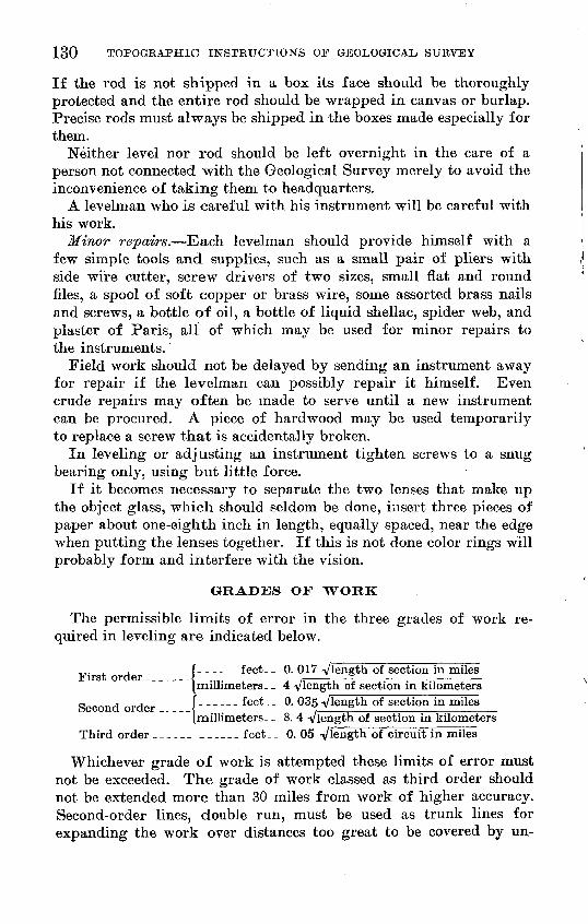
The permissible limits of error in the three grades of work re quired in leveling are indicated below.
. , f__-___ feet__ 0. 017 Vlength of section in miles"[millimeters-- 4 Vlength of section in kilometers
Second order f- ----- feet- _ 0. 035 Vlength of section in miles[millimeters-- 8. 4 -y/jength of section in kilometers
Third order ______ ______ feet-_ 0. 05 Vlength of circuit in miles
Whichever grade of work is attempted these limits of error must not be exceeded. The grade of work classed as third order should not be extended more than 30 miles from work of higher accuracy. Second-order lines, double run, must be used as trunk lines for expanding the work over distances too great to be covered by un-

LEVELING 131
supported lines of third-order accuracy. No standard bench marks should be established on lines less accurate than those of the third order.
THIRD-ORDER LEVELING WITH WYE LEVEL ANDTARGET ROD
PERSONNEL AND EQUIPMENT
The level party consists of a levelman; one or two rodmen, one of whom may act as chauffeur and be used to set permanent marks in advance of line; and in some areas a bubble tender. The equip ment issued (see pi. 7) is as follows:
One 20-inch wye level.One or two New York rods.One or two plumbing levels.Two steel turning pins.One set dies (figures and letters).One pocket compass.One 25-foot steel tape.One special invar strip testing tape.Thermometer.Bench-mark tablets.Copper nails and washers for intermediate bench marks.Cement in cans.Two paint cans.Level notebooks, 9-903 in black covers to be used by levelman; 9-903A
in yellow covers to be used by rodman. Bench-mark description book 9-916. Two book bags. Small cold chisel ( a/4 inch).
*
Other accessories, to be obtained in the field, are as follows:
One or two hatchets or Boy Scout axes.One drill hammer.One post-hole digger.Two stone drills, 1%-inch bit.
CHARACTER AND ACCURACY
Third-order leveling should be run as single lines forming cir cuits wherever practicable; otherwise the lines must be checked by rerunning, preferably in the opposite direction. No work is com plete until it is checked in some way. Lines should be connected with near-by bench marks of railroads, cities, highways, and other organizations either by making these marks turning points in the main line or on a spur line leveled twice.
The closure error, in feet, of a circuit should not exceed
0.05 Vlength of circuit in miles.

132 TOPOGRAPHIC INSTRUCTION'S OF GEOLOGICAL SURVEY
BEADING OF TARGET BOD
Both the levelman and the rodman must read each target setting independently and keep complete separate field notes.
When the target is set for the back-sight reading, the rodman must immediately read the rod and set down his reading in his notebook. He should then bring the rod forward to the levelman without chang ing the setting. The levelman then reads the rod, recording his re sult. They must not compare figures until their respective records for a given sight are completed. If the difference between the records exceeds 0.002 foot each must read the rod again before further com parison is made.
When the fore-sight target is set, the rodman must immediately read the target and record his reading. The setting should remain undisturbed till the levelman can come forward and make an inde pendent reading, and he should record the result in his book before making comparison with the rodman's reading.
When a New York rod is lengthened beyond 6.5 feet both the rod man and the levelman must examine the setting of the target as well as the reading of the rod vernier. When the rod is closed they should see that the rod vernier indicates 6.5 feet, not depending on the abutting ends to bring it back to place.
LENGTH OF SIGHT
The maximum length of sight permissible under the most favor able conditions is 300 feet, except across rivers or deep ravines. In such places reciprocal observations must be made as follows: Just before reaching the river or ravine the levelman should see that all excess in total distance by either fore sights or back sights is elimi nated. He should then establish a turning point (A) near the edge of the river or ravine, approximately opposite and level with a point (B) to be established on the opposite side. Next he should test the adjustment of the instrument. Then, with the instrument set up 20 to 50 feet from the point A, he should take a back sight on it and a fore sight on point B. He should then move across the river, set up the instrument 20 to 50 feet from the point B, and take a back sight on point A and a fore sight on point B. The mean of the two eleva tions determined for the point B will be accepted as correct. For very long sights at least four readings on the distant rod should be made and the average adopted. To minimize the refraction it is advisable to read the rod on the distant sights 3 feet or more above the ground.
EQUALIZATION OF FOBE-SIGHT AND BACK-SIGHT DISTANCES
In order to eliminate instrumental errors and errors caused by curvature and refraction the lengths of fore and back sights should

LEVELING 133
be equalized at each set-up, but if this is impracticable because of an abrupt change in grade, enough unequal sights to balance should be taken as soon as the grade is passed, before another permanent bench mark is reached and before any change in the instrument ad justment is made. The difference between sums of back-sight dis tances and fore-sight distances should not exceed 1,000 feet.
If the adjustment of the level is changed before balancing sums, any attempts to eliminate instrumental errors by taking unequal sights to balance former sights are useless.
The failure to balance sights may allow a large inclination of line of sight to affect results if not corrected by the determination and application of a slope factor (C). The levelman should make observations for this factor by the peg method (p. 141) at all places where it is found impracticable to balance the sights. The values of C should be recorded on the right-hand page of the notebook opposite the entry for the point at which they were determined, and reference should be given by page numbers to the computation and the section of the notes to which each factor is to be applied. The application of this factor need not be made in the field.
MEASUREMENT OF DISTANCES
Distances may be measured by stadia readings on the rod or by counting rails along a railroad. The distances in miles or feet of both fore sights and back sights must be recorded in the notebooks in the proper columns by both the rodman and the levelman. When stadia distances are used, the reading for distance on the back sights should be taken before and on the fore sights after the level readings are taken, in order to prevent disturbing the bubble.
BOD LENGTH AND CLAMPS
Rods must be tested for length as explained on page 129. The long rod clamps and the target clamp should be kept working smoothly so that close settings can be promptly made. The bottom of the rod must be kept clean and free from clinging dirt.
PLUMBING LEVELS
Plumbing levels must be used, tested at frequent intervals, and kept in adjustment.
TURNING POINTS
The regular steel turning-point pin should be used where no rock or other suitable point is available. When the line is being run along a railroad the higher edge of the rail or a spike may be

134 TOPOGRAPHIC INSTRUCTIONS OF GEOLOGICAL, SURVEY
used, and. the point occupied must always be distinctly cross marked with keel before the rod is held on it.
Care should be taken not to choose for a turning point a sloping surface, on which there is a possibility of the rod slipping to a lower position between sights. The turning point must be firm and free of dirt.
Do not depend on a single stake or pin driven the night before as a starting point in the morning.
RECORDING
All level notes must be recorded directly in books 9-903 and 9-903 A. The black-covered books are for the levelman's notes, and the yellow-covered ones are for the notes to be kept independently by the rodman. One set of notes must not be merely a copy of the other. Each set must be taken directly from the rod.
For a given point in the levelman's notes the rodman's notes must be at least two lines lower down the page than the levelman's, and the two men must not turn over a leaf at the same time. Eras ures of rod readings with rubber or knife are not permissible; a single line should be drawn through an erroneous record and the corrected figures written above it.
Both the levelman's and the rodman's books must be balanced daily. At the bottom of each page and at the end of each day's work the sums of columns of fore-sight and back-sight readings must be recorded and the difference determined. This difference should agree with the difference between the first and last elevations on the page, and the figures for this page check must not be omitted. The sums of the distance columns should be recorded for each page of notes, also the difference of sums of back-sight and fore-sight lengths and the accumulated excess.
The two sets of notes should be mailed to the Washington office in separate registered packages on different days.
Sample pages of the notebooks are given on pages 135-136.
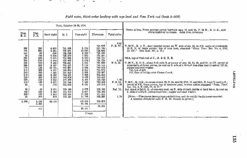
Field notes, third-order leveling with wye level and New York rod (book 9-903)
Date, October 18-20, 1924
Dist. B. S.
200195165
50205200200 20017021021021021020512050
70160200
55
3,285
Dist. F. S.
200200
80150200210200 20015020020020020015012065
55185190205
3,4503 OQC, ^oO
105
Back sight
°
4.6301.885.890
4.9347.6731.6425.203 8.457
10. 7244.3271.6910.1846.2352.8962.071.775
2.6713.3851.965.916
82. 154
H.I.
741. 508739. 594729. 698728. 370735. 004730.406729. 931 735. 457743. 867744. 605737. 363742. 451745. 098745. 306737. 794731. 073
725. 183723. 490722. 534712. 127
Fore sight
3.79910. 7866.2621.0396.2405.6782.931 2.3143. 5899.0333.9963.5882.6889. 5837. 4968.561
5.0782.921
11. 32311. 740
118. 645 82. 1,54
36.491
Elevation
736. 878737. 709728. 808723. 436727. 331728. 764724. 728727. 000 733. 143740. 278735. 572732. 267738. 863742. 410735. 723730. 298V22. 512
720. 105720. 569711. 211700.387
736. 878on 401oo. rtyj.
Check.
Total miles
0.00P. B. M.
0.45T. B. M.
1.00P. B. M.
1.05
Ref. M.
1.28
Name of line, From quarter corner between sees. 31 and 32, T. 38 N., R. 11 E., east along highway to Salem. John Doe, levelman
T. 38 N., E. 11 E., near quarter corner on W. side of sec. 32, in NE. angle of crossroads,10 ft. N. of fence corner; top of iron post, stamped "Prim. Trav. Sta. No. 4, 1919,111. 737." (See Bull. 567, p. 75.)
728.9, top of west rail of C., B. & Q. E. R.
T. 38 N., R. 11 E., about 0.13 mile S. of corner of sees. 22, 23, 26, and 27, in SE. corner of crossroads, at fence corner, in root on S. side of a 10-inch box elder tree (marked 727.0);copper nail and washer.
745, top of hill.715, floor of bridge over Canoe Creek.
T. 38 N.,R. HE., at corner of sees. 26, 27, 34, and 35; 22 ft. N. and 20ft. E. from T road to E.,inside of NE. fence corner, top of concrete post; bronze tablet stamped "Prim. Trav.Sta. No. 2, K 1924, 111. 61 D."
Ref. mark is 240 ft. E . of concrete post, on N. side of road, inside of field fence, in root onS. side of a 3^-ft. cottonwood tree; copper nail and washer.
[NOTE. The above descriptions are fictitious and do not fit the distance recorded.A location sketch for each P. B. M. should be given.]
00

£ Q
9
r2 £
s
0 S- -a
M
M
M
M
M
f-
S
to00
CO
C
O -*
[Ben
ch m
arks
sho
uld
appe
ar i
n th
is c
olum
n at
usu
al 1
-mile
or
0.5-
mile
in
terv
als
as r
equi
red
by i
nstr
ucti
ons.
]o>
o
b b
O>
O
S
I a
CD
C
O
CO
S
88
OS
<i
^t
' en
Cn r^
1 si
<=> 8 __I ^j £
O g.
® 1
?
?
?
§CD
W
O ~
O>
cC "* g)
yO
-2 j
rS
.cr_
,-<
)O
o c
f m
S V
J T
[Col
umns
om
itte
d he
re a
re u
sed
for
com
puta
tion
s, c
ompa
riso
ns,
and
corr
ecti
ons.
]
Closure
error -....---.----.--- ..... ' 1
.059
Closure
error.
Willow
Springs, 1.00
mile
east
of,
100
feet
east
of
1
side
of
road
at
fence
line,
in
root
on south
side
of
nail
and
washer
(marked
675.1).
Orlando, at
northeast
corner of
Main
and
First
Stn
table
at
southwest
corner of
Orlando
National
tablet
stamped "627
111. 1920."
(Note: See
Bu
Elevation
by
thisline---.-.---.. ... ..
Elevation
by
Bull.
672..
____ . __ . _
lid
t|
?Ǥ"
p®
0,P
CD
p g
885s
<=
4I
r»^
g^
j?&
SS
«
g
So
0010
g
-
So
-;
n °
-t
£l
O
Co
§1
§|
S n
* c
r
T.
38
N., R.
11
E., at
quarter corner betwee
n sees
and
30
feet
east
from
crossroads; 65
feet
west
of
concrete
post; bronze
table
t stamp
ed "Prim.
1
111.
60
D."
Reference
mark,
60
feet
west and
25
feet
north
fin
north
and
30
feet
west
from
crossroads, in
root
on box
elde
r tree
; coppe
r nail
and
washer.
Ref.llB.M
.x||
x
r
Willow
Springs, north
corner of
Wentworth
and
northwest end
of
stone
doorstep, 8
feet
southeast c
on southwest
side
of
Henry B.
Koller's
brick
tvertica
lly (U
. S.
Corps of
Engineers P.
B.
M. 12
616.
503616
. 444
"P
g^S
'
I3
S§J
3^ 5
&
c?§
' ffl
» co
^ " >
_.
&a
2?O
g5
° 8
<T
» "
?D'O
J
fill
If
?K
iS
f5'
P
{ «
|l
J.tj
r!'
i-l
ss.i
r^o.
29 2
. «.
8-
, to
B1
T.
38
N., R.
11
E., near quarter corner on west
si<
angle
of
crossroads, 10
feet
north
of
fence
corner; " Prim;
Trav.
Sta.
No.
4,
1919,
111.
775."
(Bull.
II
NHX
T
-q O
"^
"P 2
.c7
ib
^'P
. O 5
CO
p t
o Iff s§s^«- « s
S,s
j i
I
Description (to
be
written
in
publication foi B P Q<
d. 1 i (0 M
-^Q
'S'
CD
C3
^
sr £. p o 0.
p 1 t-1 (D g P <H O U S Line
from
quarter corner between
sees. 31
and
32,
via
Willow
Springs to
Orlando,
Qu p n9
g»
e,^
«? * d» n> CO
h~t
^M Ef
B
CB "! £ 1 E TO
i o-
o
o t to *-*
OS
rrvo
iooi
oao
,1098
1
IJEVELING 137
CAUSES OF ERROR
The use of an instrument that is slightly defective or out of adjustment will cause errors unless care is taken in balancing back sight and fore-sight distances, which reduces errors of this kind to a minimum. Other causes of error to guard against are unfavor able atmospheric conditions, the settling of turning-point pin or instrument, failure of rodman to hold on the pin, carelessness or roughness in setting rod on pin or in closing the rod, slipping of target or long-rod clamps before a reading of the rod is made, poor adjustment of rod bubbles, refraction when taking a sight too close to the ground, "boiling air," attempting to take sights of excessive length. A levelman must exercise continual vigilance to foresee and avoid conditions or incidents that may impair the accuracy of his line. Do not take a sight over 100 feet in length passing within 2 feet of intervening ground.
Work on third-order lines should not be carried on during high winds or when the air is "boiling" badly, because such conditions will affect the accuracy of the work.
CONDITION OF INSTRUMENTS
Although all instruments are adjusted and tested before they are shipped from Washington, complaints are sometimes made, even by experienced levelmen, that good results can not be obtained with the levels furnished. The levelman should, therefore, immediately on receipt of an instrument, look it over carefully and thoroughly, and if any parts are lacking or so defective as to preclude an adjust ment by him he should immediately telegraph for another level. The adjustment of the level must be tested at the beginning of each day's work and corrected if found materially in error. It niust be tested and the necessary adjustments made before taking long sights by reciprocal leveling across rivers or deep ravines. However, though it is desirable to keep the level in good adjustment in order to obtain the best results, unnecessary tampering with the adjustable parts of the instrument should, of course, be avoided.
When the line is being run the levelman should not take it for granted that the level bubble will stay centered while the level is being revolved for fore sight, but he should examine it, and if he finds it off, he should relevel it. An error of even a single division of the scale neglected in leveling up a sluggish bubble introduces an appreciable error in the rod reading on an ordinary sight. How ever, even though the level may be out of adjustment, satisfactory work can be done if all parts are screwed up snug but not too tight and fore and back sights are kept equalized.

138 TOPOGRAPHIC INSTRUCTIONS OF GEOLOGICAL SURVEY
DEFECTS OF INSTRUMENTS
Any of the following instrumental defects may produce bad re sults, especially if the sights are not equalized. The remedies are almost self-evident.
1. Glass level vial loose in its case or level-tube adjusting screws loose.
2. Glass level vial defective. Sometimes small crystals collect on the inside of the tube and make the movement of the air bubble sluggish or irregular. When this occurs insert a new vial and be sure to set it with the marked (curved) side uppermost.
3. Object glass loose in its cell or cell partly unscrewed.4. Cross-wire adjusting-screw threads worn out, or screws too
tight or too lose, or cross wires themselves too loose.5. Tripod points or tripod leg-clamp screws loose.6. Leveling screws too tight or too loose.Two other possible sources of error are not so easily found, but
fortunately they need seldom be considered:1. The two telescope rings, which rest on the wyes, may be of
different size or of irregular shape.2. The object-glass slide may be out of adjustment.If the instrument has either of the two defects last mentioned
another instrument should be ordered by telegraph and the defective one returned to the Washington office.
ADJUSTMENT OF INSTRUMENTS
The customary adjustment of the wye-level should be taken up in the following order: (1) Collimation, (2) motion of object-glass tube, (3) horizontality of thread, (4) eyepiece slide, (5) level-vial direction, (6) level-vial inclination, (7) wyes.
Collimation. Remove all parallax by focusing the eyepiece with the sky as a background until a distinct image of the cross wires is obtained. Loosen and raise the wye clips, focus, and set the inter section of the cross wires on a point, such as a nailhead, 300 feet or more away, revolve the telescope halfway around in the wyes, and note whether or not the intersection of the cross wires moves away from the point. Should the horizontal wire be found above or below the point, bring it halfway back by the capstan-headed screws per pendicular to it. Repeat the operation until it will reverse correctly. Proceed in the same manner with the other wire until the adjust ment is complete. Erecting telescopes require a movement of the reticule screws as if to increase apparent error.
Motion of object-glass tube. When the collimation adjustment is perfected for distances of 300 feet or more as described above,

LEVELING 139
proceed to test it for a distance of 20 or 30 feet, and if coincidence is not obtained after revolving the telescope on the near-by point it is evident that the object-glass slide is out of adjustment. To correct the error remove the bubble tube and the ring near the middle of the telescope and with a screw driver turn the screws, each pair in succession, until the cross-wire intersection will coincide with the near-by point while the telescope is revolved 180° in the wyes. When the collimation is perfect for both long and short sights, replace the telescope ring and the level-bubble tube. This adjustment is seldom required.
BorizontaHty of thread. Level the instrument carefully with wye clip pins in place, and select or set some point at the exact elevation of one extremity of the horizontal wire; clamp the spindle and with the tangent motion turn the instrument on its vertical axis until the opposite side of the field of view is reached; note whether or not the opposite extremity of the horizontal wire now coincides with the point selected. If it does not, it can be made to coincide by loosening one vertical and one horizontal capstan-headed screw and turning the reticule until perfect horizontality is obtained. A plumb line on the vertical edge of a building may be used to test the ver- ticality of the vertical wire. Always retest and correct any derange ment to the line of collimation which this movement of the reticule may have caused before proceeding further.
Eyepiece slide. The adjustment of the eyepiece tube so that the cross-wires will appear in the center of the field, is not essential to the accuracy of the work but may be effected by means of the screws underneath the ring just back of the cross-wire screws. Loosen one and tighten the opposite one of these screws with a screw driver until the wires appear centered.
Level-vial direction. When the bubble has been carefully cen tered, with the instrument clamped parallel to opposite leveling screws, loosen the clips and rotate the telescope around its horizontal axis in the wyes about 20° each way from the normal position, mak ing sure that the wyes are free from dirt; if the bubble moves away from the center toward opposite ends alternately, bring it all the way back by the side or azimuth adjusting screws by loosening one and tightening the other. In the ordinary wye level the two rings on the telescope tube that rests in the wyes are assumed to be cir cular and exactly equal by construction, but if they are not the bubble will run toward the same end when the level is rotated either way from the normal position. Under such conditions an inclina tion of the line of sight will exist after the usual adjustments are apparently satisfactory, and the only course left open is to treat the instrument like a Dumpy level and to adjust the level to the
58515° 28 10

140 TOPOGRAPHIC INSTRUCTIONS OF GEOLOGICAL, SURVEY
telescope by the peg method described on page 141. This is a more direct adjustment and gives a positive useful measure of the inclina tion of the line of sight.
Level-vial inclination. When the bubble has been carefully cen tered with telescope in normal position but with clips open, lift the telescope out of the wyes, reverse it end for end, and replace it in the wyes; if the level bubble has moved away from the center bring it halfway back by means of the capstan adjusting nuts at one end of the level tube and the rest of the way by the lower leveling screws. Repeat this operation until the adjustment is perfect, and close the clips.
Wyes. After each of the foregoing tests and adjustments have been made, the wyes can be adjusted. This is done by turning the telescope and level 180° on its vertical axis; if the bubble, which was at first in the center, moves away, bring it halfway back by changing the setting of the pair of large capstan nuts under one wye and the remainder of the way by the base screws. This wye adjustment is relatively unimportant and is made more as a matter of convenience than of necessity.
SPECIAL ADJUSTMENTS
All instrumental errors may be compensated in each set-up by the exact equalization of back-sight and fore-sight distances, but as this can not always be done it is important to know the amount of error introduced when a balance is not maintained. The level and colli- mation adjustments are the most important of the regular wye-level adjustments, but a large deviation of the line of sight from parallel ism with the level vial, due to unequally worn or deformed rings or unequal pressure of clips, may exist and will not be revealed by the usual adjustments. Information as to this deviation is desirable, however, and should be obtained, in order to show the condition of the instrument and to take it into account when sights have not been well balanced. The existence of this deviation is ascertained by means of the peg-method test for the determination of C.
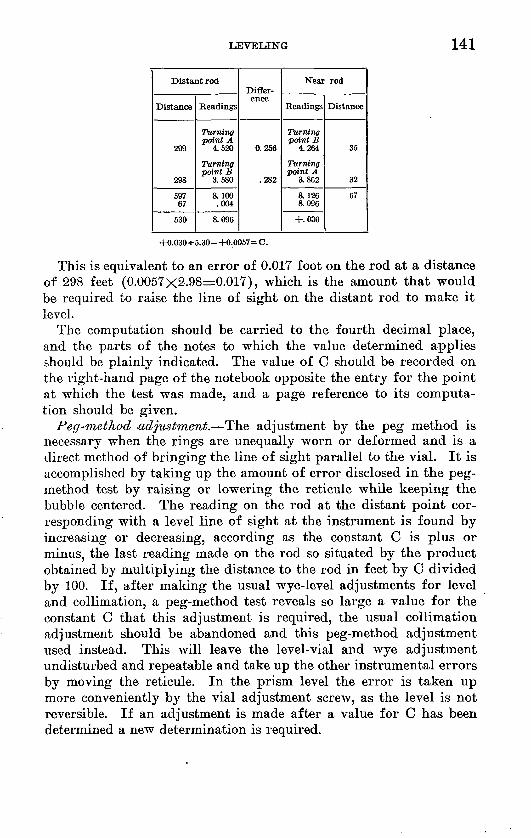
Peg-method test for determination of C. Use two turning points about 300 feet apart and at nearly the same elevation. Set up the level about 30 feet from one point, and with the bubble centered take readings on the rod for both points. Repeat the operation from a set-up 30 feet from the other point. From these readings and dis tances determine the inclination of the line of sight per 100 feet of distance, which is the constant C. The value of C is expressed by the following formula : C= (sum of near-rod readings minus sum of distant-rod readings less 0.004 feet for curvature and refraction )-^ (difference between sums of long and short sight distances-KLOO). Example:
LEVELING 141
Distant rod
Distance
299
298
597 67
530
Readings
Turning point A
4.520
Turning point £
3.580
a 100 .004
8.096
Differ ence
0.256
.282
Near rod
Readings
Turning point B
4.264
Turning point A
3.862
8.126 8.096
+.030
Distance
35
32
67
+0.030-«-5.30 = +0.0057= C.
This is equivalent to an error of 0.01T foot on the rod at a distance of 298 feet (0.0057x2.98=0.017), which is the amount that would be required to raise the line of sight on the distant rod to make it level.
The computation should be carried to the fourth decimal place, and the parts of the notes to which the value determined applies should be plainly indicated. The value of C should be recorded on the right-hand page of the notebook opposite the entry for the point at which the test was made, and a page reference to its computa tion should be given.
Peg-method adjustment. The adjustment by the peg method is necessary when the rings are unequally worn or deformed and is a direct method of bringing the line of sight parallel to the vial. It is accomplished by taking up the amount of error disclosed in the peg- method test by raising or lowering the reticule while keeping the bubble centered. The reading on the rod at the distant point cor responding with a level line of sight at the instrument is found by increasing or decreasing, according as the constant C is plus or minus, the last reading made on the rod so situated by the product obtained by multiplying the distance to the rod in feet by C divided by 100. If, after making the usual wye-level adjustments for level and collimation, a peg-method test reveals so large a value for the constant C that this adjustment is required, the usual collimation adjustment should be abandoned and this peg-method adjustment used instead. This will leave the level-vial and wye adjustment undisturbed and repeatable and take up the other instrumental errors by moving the reticule. In the prism level the error is taken up more conveniently by the vial adjustment screw, as the level is not reversible. If an adjustment is made after a value for C has been determined a new determination is required.

142
THIRD-ORDER LEVELING WITH PRISM LEVEL ANDYARD RODS
PERSONNEL AND EQUIPMENT
A prism-level party consists of one levelman, two rodmen, a re corder, and a general utility man. The instruments and outfit (see pi. 7) consist of the following:
One prism level.Two yard rods, each to have plumbing level and thermometer attached.One steel tape (25 feet).One special invar testing tape.Two steel turning-point pins.Two rawhide mallets.One pocket compass.One Locke level.One set of dies (figures).Bench-mark tablets or posts.Copper nails and washers for temporary bench marks.Cement, paint can, keel, and other accessories.Two book bags.Prism level notebook 9-940 or 9-940A.Bench-mark description book 9-916.
CHARACTER AND ACCURACY OF LINES
Third-order levels executed with a prism level ordinarily need be run in one direction only but must be checked by closing circuits or releveling or otherwise. Circuits must close with an error in feet not exceeding 0.05 V length of circuit in miles. Steps to be taken if the closure is in excess of this amount are explained in the first part of these instructions (p. 127).
GRADUATION OF ROD
The rods used are graduated to yards, tenths, and hundredths and are read by estimation to thousandths. Each yard has a different and distinctive color, which must be recorded for each reading. One edge of the rod has also graduation in tenths of feet, numbered, for use as a check on yard readings, and some rods have "double yard " graduations to be used as a check. These rods are of the " self- reading " type and have no targets.
METHODS OF OBSERVATION
Third-order lines of levels may be run in two ways with the prism level by reading all three horizontal cross wires on the rod, or by reading the middle one only. The three-wire method gives more accurate results and makes available a greater number of checks

LEVELING 143
against errors, but the keeping and computation of the field notes are somewhat more cumbersome. The one-wire method has a slight advantage in speed and simplicity.
THKEE-WIRE METHOD
In the three-wire method the program at each set-up is as fol lows : After the tripod is firmly set and the clamp screws tightened, level approximately by the circular level, which has been adjusted by comparison with the long level. Point the instrument toward the back rod and clamp; bring the level bubble to the center of the tube by means of the micrometer screw. Read on the rod and, first, call off the color initials for the lesser and greater extreme readings; second, call yards and tenths for each wire, taking the smallest read ing first; third, repeat and read yards, tenths, hundredths, and esti mated thousandths; fourth, for additional check on the yard number, read the middle wire on the tenths of feet scale on the back of the rod, estimating and recording to hundredths of a foot. When the recorder has checked the back sight he signals the rear rodman to come ahead. Meanwhile the levelman sights the front rod and takes the fore sight as soon as the recorder has checked the back sight but does not move his instrument until the recorder has also checked the fore sight. The front rodman remains at his turning point, guarding it carefully against disturbance. The levelman moves for ward to his next set-up, and the free rodman advances to a new turning point. Hodmen should never exchange rods.
Prism-level notebooks (9-940A) should be used when readings are to be made on all three cross wires. The horizontal lines in these books are in groups of four, and the bottom line of each group is red. Each group is intended to cover a single set-up of the in strument, the back sight on the left and the fore sight on the right. Sample pages of level notebooks are given opposite page 144.
The seven columns on the left-hand side of the book, from left to right, are used as follows: In the left part of column 1 are written the yard color initial of the first and last yard readings and the check reading in hundredths of a foot, the last figure being esti mated; in the right part of the same column are placed the three yard readings to thousandths of a yard. In column 2 are given the interwire intervals, found by subtracting the least yard reading from the middle and the middle from the largest. If the three cross wires are equally spaced these two interwire intervals should be within 0.002 or 0.003 yard of being the same, thus giving a check on the yard readings. The wires are so spaced that either one of these intervals, as read on a yard rod, will give a stadia distance to the rod in feet that is, the interval between the middle wire and

144 TOPOGRAPHIC INSTRUCTIONS OP GEOLOGICAL, SURVEY
either one of the others will subtend 0.1 yard on the rod for every 100 feet of distance to the rod. The continuous accumulating sum. of the interwire intervals between the least yard reading and the middle is carried along from set-up to set-up, starting with zero at each permanent bench mark. This sum of back-sight distances, which is written on the fourth line of each group, may then be com pared at any time with the sum of fore-sight distances to see how nearly fore-sight and back-sight distances agree. If the continuous sum of interwire intervals is not carried along in this manner the net excess of the page sums of interwire intervals for one column down to the bottom of each page should be placed at the top of the same column on the next succeeding page. Added together these amounts give the distance run from the last permanent bench mark. Column 3 is for the sum of the three yard readings, which is equiva lent to the mean of these three readings converted to feet, and it is checked by the readings in hundredths of a foot taken on the back of the rod. Column 4 is used for H. I. and elevation.
The space above the short black line is for the H. I., and that below the line for the elevation. Columns 5, 6, and 7 are for the fore sight, and are used in the same way as columns 3, 2, and 1, respectively. Thus in each fore sight or back sight there are three independent checks: The color initial checks the first figure of the yard readings, the inter-wire intervals check the difference of the yard readings, and the foot reading on the back checks the sum of the yard readings. These three checks must be made for the back sight before the back rodman moves his turning-point pin, and for the fore sight before the instrument is disturbed. When a bench mark is reached, the page sums of columns 3 and 5 should be com pleted, and the levelman should also make corresponding sums of the foot readings in columns 1 and 7 as a check. Also, either the recorder or the levelman should add the middle-wire yard readings in both columns 1 and 7, and multiply each sum by 3. This will check the sums for columns 3 and 5 if the algebraic sum of the discrepancies of the inter-wire intervals is considered. If column 4 is filled in, the usual page check should be made, the difference of the sums of columns 3 and 5 being used to check the difference of the first and last elevations on the page. Show all such computa tions in full.
If in the body of the page the record is reached of a point for which the elevation is to be computed, the H. I. and elevation must be entered throughout the page. Otherwise it is permissible to carry the elevation through the page by means of the totals of columns 3 and 5, using the total of column 3 as a back-sight reading to be added to the elevation brought forward from the preceding

Field notes by prism level and yard rod and three-wire method (book 9-940A}
Date: June 8, 1925. John Smith, recorder
Back sight
Thr. Rdg.
B 0. 365 1.34 0.447
B 0. 528
B 0. 363 1.35 0.448
B 0.533
B 0. 277 1. 07 0. 359
B 0.441
B 0. 563 1.91 0.636
B 0. 707
B 0.017 0. 75 0. 248
B 0. 478
' O 2. 394 8. 17 2. 727
Y 3. 058
Y 3. 184 10. 02 3. 339
Y 3.493
Y 3. 094 9. 67 3. 226
Y 3. 356
R 1.913 6. 57 2. 191
Q 2. 463
Thr. Int.
782
82 81
85 85
167 82 82
249 73 71
322 231 230
553
1,443
333 331
886 155 154
1,041 132 130
1,173 278 272
1,451
Sum T. R.
1.340
1.344
1.077
1.906
0.743
feet =
8.179
10. 016
9.676
6.567
Sums for page
13. 621 3
40.863 40. 848
H.I. (feet)
Elev. (feet)
327. 861
329. 201
318. 641
319. 985
310. 089
311. 166
301. 804
303. 710
297.246
297. 989
294. 257
0. 27 mile
302. 436
300. 953
310. 969
308. 574
318. 250
317. 201
323. 768
315.911
Elev. Elev. 11. 950
B CJ T? Ci
11. 950
Fore sight
Sum T. R.
Thr. Int. Thr. Rdg.
(Elevation brought forward from page ..-.)
10. 560
9.896
9.362
6.464
3.732
1.483
2.395
1.049
7.857
89 89
76 75
165 86 85
251 269 265
520 370 370
890
175 173
1, 065 115 113
1,180 186 185
1,366 263 263
1,629
3. 431 Y 3. 520 10. 56 3.609 Y
3.223 Y 3. 299 9. 89 3.374 Y
3. 035 Y 3. 121 9. 36 3.206 Y
1. 887 R 2. 156 6. 47 2. 421 G
0. 874 B 1. 244 3. 74 1. 614 R
0. 320 B 0. 495 1. 47 0. 668 B
0. 684 B 0.799 2.40 0. 912 B
0.164 B 0. 350 1. 06 0. 535 B
2. 356 Q 2. 619 7. 86 2. 882 O
Sums for page
52. 798
17. 603 3
52. 809
Line from Troutdale, via . _ , to Essex
Miles
24.45
24.72
Descriptions (including elevations)
Clear; strong wind; 65°.
Union City, 4 miles NW. of, at foot of long hill, 100 feet E. of road forks to N., on E. end of head wall of small concrete bridge; chiseled square.
Road turns to NE.
T. P. on south rail at R. R. crossing.
782 -178
604 excess B. S.
3,080 feot=0.58 mile; 25.03 total miles.
58515° 28. (Face p. 144.)
LEVELING 145
page and the total of column 5 as a fore-sight reading to be sub tracted from the result of this addition to obtain the elevation to carry forward to the next page.
If a bench-mark description falls in the middle of a page, it is advisable to skip one of the four-line spaces before continuing the notes, thus giving room for distance totals, etc. The bench-mark descriptions are to be written in book 9-916 in the same form as for wye-level results. (See p. 136.)
In using two rods on alternate turning points, give the number of each rod occasionally alongside the record of a fore sight on which it was used.
ONE-WIRE METHOD
In the one-wire method rods having the double yard graduation on the back should be used. The program at each set-up is the same as described for the three-wire method, except for the reading and recording. The stadia distance is first read while the instrument is being leveled. Then, by the middle wire only, are read, first, the yard color initial; second, the yard, tenth, hundredth, and estimated thousandth; and third, the "double yard" reading estimated to thousandths. These readings are recorded in field book 9-940. A sample of field notes is given on page 146. The horizontal lines are in groups of two, each group covering one set-up. The upper line of the two should be used for recording the back and fore sights and the H. I. for the set-up. The elevation of the forward turning point should appear by itself on the lower one of the two lines. In column 1 are entered the color initial of the middle wire reading and the distance to the rod in feet, obtained by reading stadia on the rod. Column 2 is for the check reading in " double yards," column 3 for the yard reading, column 4 for H. I. and elevation placed as noted above. Columns 5, 6, and 7 are for the fore sight and are used like columns 3, 2, and 1, respectively, for the back sight. The recorder should mentally multiply each double-yard reading by 2 and compare the result with the corresponding yard reading, thus obtaining a check of not more than 0.001 yard above or below, before the next sight is taken or the turning point or instrument dis turbed. The yard readings are used to compute the H. I. and eleva tion in column 4 through every page. These values are therefore in yards. Computations of bench-mark elevations in feet are to be placed on the right-hand page. The usual page check must be made for every page by comparing the difference of the sums of columns 3 and 5, multiplied by 3, with the difference between the beginning and ending elevations for the page, converted to feet, this computa tion to be shown in full. The sum of the distances in columns 1 and 7,
146 TOPOGRAPHIC INSTRUCTIONS OF GEOLOGICAL SURVEY
converted to miles, is entered to show the total miles from the last permanent bench mark. A two-line group should be skipped before continuing the record after establishing a bench mark. Bench-mark descriptions are written in book 9-916 in the same form as for wye- level lines. (See p. 136.)
LENGTH OP SIGHTS
The length of fore and back sights should be equalized with the prism level as with the wye level. The maximum length of sight with the prism level is 360 feet except at river crossings, where the mean result of reciprocal observations should be taken between one pair of pegs at nearly equal elevations on opposite banks.
Mount the instrument first near one peg and then near the other so that the center wire will fall near the middle of each rod; if the distance is too great to read the three wires, use improvised targets of cardboard held in place by rubber bands or some other simple device, and make several settings by raising and lowering them an equal number of times. Hodmen should be provided with field glasses if necessary to read signals. From bench marks on each bank the elevation of the adjacent water surface should be deter mined as an additional check.
MEASUREMENT AND USE OF BODS
Testing of the rods in the field for length is very important. On wooden yard rods small metal plugs are set into the faces at inter vals, each bearing a fine graduation; these are for use in testing the rods. These tests are made as explained on page 129.
The rods must be kept covered when not in use. The painted sides must not touch the ground. Should difficulty be found in holding a rod steady because of wind, two pieces of bamboo or other light poles, 8 feet long, may be held by the rodman against the rod, so as to make a triangular brace against the wind. Plumbing levels must frequently be tested and kept in adjustment.
ADJUSTMENT OF PRISM LEVEL
When the work is cotamenced, and at least once each day there after, the adjustment of the level must be tested by the "peg method," either by making two separate set-ups, apart from the line, as described for testing the wye level (p. 148), or by utilizing one of the sights of the line itself, thus saving one set-up. If the latter procedure is used care must be taken not to get the extra
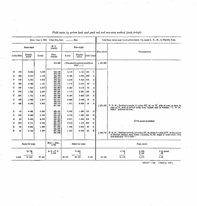
Field notes by prism level and yard rod and one-wire method (book 9-940}
Date: Jan. 9, 1925. John Doe, Lev. ___ . Rec.
Back sight
Color Dlst.
B 160
R 300
Y 270
R 200
Y 200
Y 200
Y 200
0 190
Q 100
B 40
B 100
B 90
B 200
R 40
R 30
Double yards
0.050
0.777
1.505
0.566
1.835
1.669
1.725
1.488
1.040
0.483
0.358
0.390
0.171
0.903
0.749
Yards
0.100
1.554
3.010
1.131
3.670
3.339
3.450
2.977
2.092
0.965
0.716
a 792
0.342
1.806
1.499
Sums for page
13. 7212
2, 320 27. 442 27. 443
H.I.(yards)
Elov. (yards)
395. 200
395. 320392. 150393. 704393. 514396. 524395. 596396. 727395. 612399. 282399. 046402. 385401. 210404. 660404. 480407. 457406. 653408. 745407. 534
408. 449405. 779406. 495403. 731404. 523401. 852 402. 194399. 844401. 650399. 900401. 399399. 926
Elev. Elev. 4.706
B.S.-F.S.4.706
Fore sight
Yards Double yards Dist. Color
(Elevation brought forward frompage ....)
3.170
0.190
0.928
1.115
0.236
1.175
0.180
0.804
1.211
2.720
2.764
2.671
2.350
1.750
1.473
1.585
0.095
0.464
0.557
0.118
0.587
0.090
0.402
0.606
1.360
1.382
1.336
1.175
0.875
0.736
300 Y
280 B
360 B
80 R
50 B
130 R
150 B
70 B
40 R
190 0
140 Q
150 G
160 G
20 R
30 R
Sums for page
11. 3682
22. 737 22. 736 2, 150
Line from point near Crownovcr ranch, via roads S., E., N., to Marble Falls
Elev. (feet)
1, 185. 660
1, 222. 602
1, 199. 778
Descriptions
T. B. M., Beakley's ranch 1.5 miles SE. of, on W. side of road at turn, in root on N. side of forked cedar tree; copper nail in washer; "T. B. M.1222.6" painted on tree.
[Give usual sketches]
P. B. M., Beakley's ranch, 1.8 miles SE. of, about 0.7 mile NW. of the corner of Burnet, Blanco, and Llano Counties, in SE. angle of cross roads; ironpost stamped " C-7-1925."
Page check
4. 706 2, 320 3. 51 miles3 2, 150 . 85
14.118 14.118 4,470 4.36
58515° 28. (Face p. 146.)

LEVELING 147
sights confused and introduced into the line, in place of or in addi tion to the regular sights. To do so would introduce a gross error.
Peg-method test and computation of C. At some convenient set-up, having a full-length fore sight, after the usual back-sight and fore-sight readings have been recorded, copy the fore-sight reading on the right-hand page for use as a long test sight. Set an extra turning point about 30 feet back of the instrument, and read the rod on it for a short test sight. Move the level forward to an extra set-up about 30 feet back of the regular fore-sight pin, and read the rod on it for the second short test sight. The rod is read also on the extra turning point, for the second long test sight. The test sights are now all obtained, and the extra turning-point may be moved, the instru ment carried forward, and the line continued as usual from the regular turning point. The two long test sights, recorded one under the other on the right-hand page, and the two short sights, similarly recorded, should be marked "Determination of C." Test sights should be taken in the same manner as the regular sights, three wires or one wire being used according to the way the line is being run.
The constant C, which is a factor of the adjustment correction, must then be determined. It is the sum of readings on near rods in feet minus that on far rods (corrected for curvature and refraction) in feet divided by the difference between the sum of the greater and that of the lesser distances in feet and multiplied by 100. It is the amount, in feet per 100 feet of distance, that the line of sight slopes when the bubble is centered. 1
When the sum of the readings on the near rods is the greater, the sign of C is plus and the line of sight is too low. Care should be taken to give the proper sign and proper position of decimal points. Curvature and refraction correction for the sum of the long sights in feet is obtained by the formula 0.00041 (mean length of long sights ~ 100) 2 . This correction is of such sign as to be always subtracted numerically from the long-sight readings. Examples of the com putation of C are given below. In the expression for C by the three- wire method the approximate sums and difference of sums of lengths of long and short sights in hundreds of feet are derived from the corresponding sums and difference of sums of lower or upper thread intervals in yards by moving the decimal point one place to the right.
1 C as used by the U. S. Coast and Geodetic Survey is the amount of slope, in meters, per meter of total rod intercept or interval between the stadia wires. This is not the same as the amount in meters per 100 meters or feet per 100 feet, because the stadia constant of the levels used by that bureau is 0.003. Therefore the numerical value of C as used under these instructions represents a slope 3.33 times the slope corresponding to the U. S. Coast and Geodetic Survey formula., The difference should be borne in mind when comparing the limits of instrumental error allowed without readjusting. The U. S. Geological Survey prism level stadia constant is 0.006,
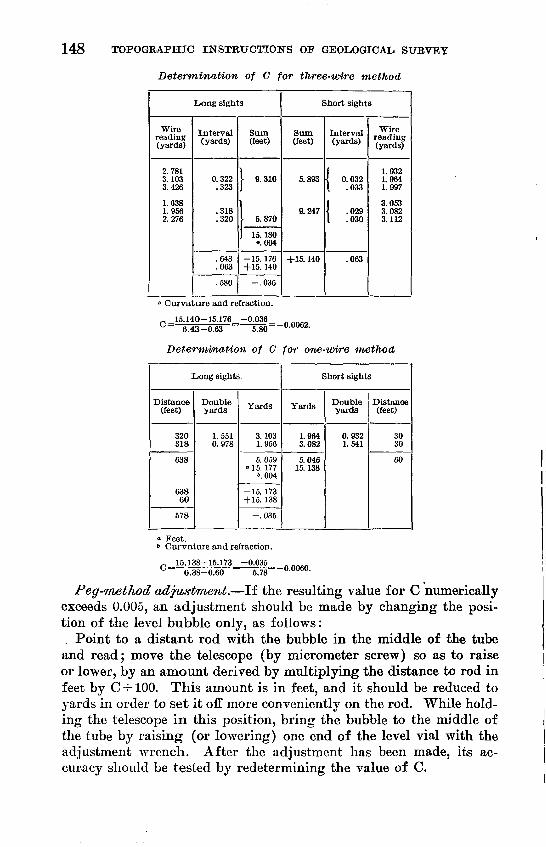
148 TOPOGRAPHIC INSTRUCTIONS OF GEOLOGICAL SURVEY
Determination of C for three-wire method
Long sights
Wire reading (yards)
2.781 3.103 3.426
1.638 1.956 2.276
Interval (yards)
0.322 .323
.318
.320
.643
.063
.580
Sum (feet)
I 9. 310
5. 870
15. 180 o.004
-15. 176 +15. 140
-.036
Short sights
Sum (feet)
5.893
9.247
+15. 140
Interval (yards)
{ 0.032 .033
\ .029 I .030
.063
Wire reading (yards)
1.932 1.964 1.997
3.053 3.082 3.112
0 Curvature and refraction.
15.140-15.176^-0.036 0 6.43-0.63 ~TSO= -0-0°62.
Determination of C for one-wire method
Long sights
Distance (feet)
320 318
638
638 60
578
Double yards
1.551 0.978
Yards
3. 103 1.956
5.059 ° 15. 177
\ 004
-15. 173 +15. 138
-.035
Short sights
Yards
1.964 3.082
5.046 15. 138
Double yards
0.932 1.541
Distance (feet)
30 30
60
Feet.Curvature and refraction.
15.138-15.173 -0.035 _ {-J "^ ^ oo n at\ ==3 Er TO=3 0.0060.
6.38-0.60 6.78
Peg-method adjustment. If the resulting value for C numerically exceeds 0.005, an adjustment should be made by changing the posi tion of the level bubble only, as follows:
. Point to a distant rod with the bubble in the middle of the tube and read; move the telescope (by micrometer screw) so as to raise or lower, by an amount derived by multiplying the distance to rod in feet by C-^-100. This amount is in feet, and it should be reduced to yards in order to set it off more conveniently on the rod. While hold ing the telescope in this position, bring the bubble to the middle of the tube by raising (or lowering) one end of the level vial with the adjustment wrench. After the adjustment has been made, its ac curacy should be tested by redetermining the value of C.

LEVELING 149
In case the cross wires break and the level-tube adjustment has not been disturbed, insert new spider threads and determine value of C, as above directed. Compare with the last determination of C, and adjust for the difference by changing the position of the cross- wire ring only not the level bubble.
When both level and cross wires have been disturbed the cross wires can be put in proper position by means of improvised wooden wyes in which the telescope is turned while watching a clearly de fined point through it, the operation being the same as for the colli- mation adjustment for a wye level. The length of the air bubble in the graduated level vial can be regulated by means of the air chamber in one end of the glass tube. There is a small passageway in the lowest part of the tube between the air chamber and the main level tube; when one end of the telescope is held considerably lower than the other, with the leveling screws uppermost, if the air cham ber end is then the lower, bubbles will be seen rising through the liquid; these added to the large bubble will make it still larger, but if no bubbles appear and the large bubble grows smaller, it indi cates that the air chamber is in the upper end. Note the effect at the first trial and act accordingly in future. When the level is being carried from station to station, if the tripod is held nearly vertical the bubble will not change in length.
When leveling up at the beginning of a day's work, set the tele scope parallel to two leveling screws and level; turn it 90° and again level. Turn the level 180° and then 90° and test in both po sitions. If the bubble moves away from the center, bring it half way back by means of the leveling screws and the remainder by the micrometer screw. When the leveling is perfect adjust the circular level to agree with the other level and note the reading of the mi crometer head. The reading should be maintained for the day as nearly as possible to that thus found. The instrument should be so carefully leveled with the leveling screws at each set-up that there will be no material difference between the readings of the microm eter head for fore and back sights; a failure to observe this precau tion may introduce uncompensating errors.
CARE OF INSTRUMENT
When the level is on the tripod, be sure that the central tripod clamp screw is tight. Keep the telescope off the micrometer-screw bearing while carrying it between stations. Leave the three tripod wing nuts loose when carrying; clamp tight when tripod is in place for work. The micrometer screw should be cleaned and oiled slightly every two or three days.
150 TOPOGEAPHIC INSTRUCTIONS OP GEOLOGICAL, SURVEY
If the level can not be shaded from direct sunlight by an um brella when in use, a piece of white cloth or frosted celluloid about 8 inches square may be fastened over the top of the instrument with rubber bands, so as to allow only diffused light to reach the bubble and prisms. While not being used and still on the tripod, the instru ment should be set in the shade or a cloth hood thrown over it.
In running lines by the one-wire method there is danger of error through reading the wrong horizontal wire, as all instruments have stadia wires. This possibility may be avoided by revolving the reticule a quarter turn so as to bring the single wire horizontal, and the instrument may be regularly used in this manner. If this is done the rod'may be held horizontal for the stadia reading.
TURNING POINTS
With the yard rod having a hemispherical foot serious errors may result if turning points are taken on the highest point of a rock or nail, as it is difficult to set the rounded shoe in its highest position on such a point. It is better to find a slight nick or de pression into which the rounded shoe can settle to a definite position. It is always best, however, to use the regular turning-point pins made for the purpose, wherever there is a chance to drive them into a firm position, even if other hard surfaces are available. A wooden or rawhide mallet should be used to drive the pins. Rods should be set upon the pins gently, so as not to cause them to move or settle.
Certain unfavorable conditions and other causes of error, men tioned on page 137 in connection with work when a wye level is used are also applicable to lines run with a prism level.
SECOND-ORDER LEVELING
PUBPOSE
Trunk lines of second-order leveling must be run as a framework upon which to base third-order leveling where first-order lines are too far apart to give effective control. These lines should follow as nearly as possible the trunk lines of transit traverse that is, in lines not over 50 miles apart, so that no point will be over 25 miles from a main control point of second or higher order.
The prime requisites of through trunk lines are accuracy and re liability, and if there is a choice of route, that route should be chosen which will assure the most accurate line rather than the one that may give more conveniently located control for the topographer. The topographer's needs may be satisfied by side loops of a lower

LEVELING 151
grade. Every effort, both in office planning and in field work, should be made to have these trunk lines run and subjected to a preliminary adjustment, before other work is based upon them. If the trunk line can not be completed in advance, that part of the local work that is run over the route of a planned trunk line should be run in the manner prescribed for the trunk line, thus making a completed link that may later be connected up as a full- weight part of the trunk line.
PERSONNEL AND EQUIPMENT
For second-order leveling the instrumental outfit and the num ber of men in the party are the same as for third-order leveling with prism level, except as hereinafter noted. Some refinements of field methods are necessary beyond those required for third-order leveling, in order to insure the required accuracy. The work should be done with the prism level, by the three-wire method.
CHARACTER, ACCURACY, AND PROCEDURE
Lines must be run independently in both the forward and the backward direction.
The back runnings may start from points on the forward-run line and may be run in such sequence as may be convenient, except that they should not be allowed to lag too far behind the forward run ning. When the allowable error, in feet, for sections between bench marks exceeds 0.035 \/distance between bench marks in miles the forward or backward measurement is to be repeated until a pair run in opposite directions is obtained between which the divergence falls within this limit. It is especially desirable to make the backward measurement in an afternoon if the forward measurement was made in the forenoon, and vice versa. The ob server should make the two measurements under atmospheric con ditions as different as possible without materially delaying the work for that purpose.
The last set-up of one running must not be copied nor used as the first set-up of a return running that is, the instrument must be moved so that an independent reading can be obtained.
Whenever a blunder, such as a misreading of 1 yard or one-tenth or an interchange of sights, is discovered and the necessary correc tion is applied, the running containing it may be retained, provided there are at least two other runnings over the same section which check it and are not subject to any uncertainty.
The field work must in general conform in the instructions for third-order leveling with the prism level by the three-wire

152 TOPOGRAPHIC INSTRUCTIONS OF GEOLOGICAL SURVEY
method. (See pp. 143-145.) In order to insure the increased accu racy required, such precautions as careful rod and instrument tests, equalization of fore and back sight distances, and care in selecting turning points must receive particular attention. Yard rods having graduations on an inlaid invar strip instead of on wood are to be pre ferred. An umbrella should be provided to shade the instrument when it is set up, and a cloth hood should protect it from the sun when moving from one set-up to the next. The instrument should be very carefully handled and must not be subjected to jars and jolts such as those resulting from riding uncushioned on the floor of an automobile.
RECORDING
Two sets of field books should be used, one for forward running, which should be kept as an unbroken continuous line, and the other for backward runnings, which should show each section complete and continuous in itself. The sections can not be shown in any particu lar order in the backward-running books, as their sequence will de pend upon the field program adopted in the rerunning. Bench marks need be described only in the forward-running books, but they should receive consecutive numbers and letters, which should appear in the backward-running books also, in order to identify the cor responding marks in the two books. The consecutive numbers should be the same numbers as the identifying numbers stamped on the bench marks. For a supplementary bench mark the same consecutive number should be used as for the next preceding permanent or stamped mark, and consecutive subordinate letters added until the next permanent mark is reached; thus the sequence might be, for example, C-23-1925, 23A, 23B , etc., C-24-1925, representing permanent mark 23, two supplementary marks following it, and permanent mark 24. In addition to the use of these numbers, careful and complete book and page cross references should be made between the two sets of books, in order that no confusion or doubt may arise in finding the proper pair of runnings for any given section.
SECTION CHECK
In the forward-running book the difference of elevation should be computed for each section of the line between bench marks, perma nent or supplementary, and should appear, with the complete compu tation, on the right-hand page near the end of the space allotted to the section. The full computation of the difference of elevation ob tained by the backward running should appear with the notes for that running, and the difference itself should be brought over into the forward-running book for comparison. These differences must
LEVELING. 153
be in agreement within the limits prescribed above, or it will be nec essary to make additional runnings, which should be recorded in the backward-running books, even though the runnings may be in the forward direction.
In running lines with the prism level and the three-wire method the elevation and H. I. need not be computed throughout the page. Differences of elevation should be computed by means of the page totals from bench mark to bench mark, and elevations carried for ward by means of these differences, great care being taken to apply them in the proper direction.
DESCRIPTION BOOK
Descriptions must be copied into the bench-mark book (9-916) in consecutive order, as in third-order leveling. Field-book elevations, however, are not to be copied into the bench-mark book, but instead the differences between bench marks are to be copied. These should appear in a column to the right of the elevation column, one under the other, beginning just below the line upon which the elevation of the first bench mark is shown. The mean of these two differences is then set down in the next column to the right, and this mean is applied to the first elevation to obtain that for the second bench mark. Thus in the bench-mark book the mean line elevation is car ried forward by means of the differences between bench marks. The mean line elevations should then be copied into the forward field book, on the right-hand page above the description of the bench mark to which they apply, and a circle drawn around them to dis tinguish them from the field-book elevations. If field-book eleva tions have been carried through in the forward-running book in the usual manner, rough comparison with the mean line elevations will serve to check the proper use of the sign in applying the differences between bench marks.

Record in description book (9-916)
Level No. 163. Rod Nos. T-32, T-42. Levelman, John Doe
Date (1925)
June 2
2 3
23
232
Interpol
22
445
Outoflii
55
(5
Level book
No.
3F3B
3F 3B
3F3B
3F3B3F
ited or
3F3B
3F3B3B
aits; t
3F3B3B
Page
2141
22 46
2344
254326
i first i
2742
284843
sethir
294242
Miles by route
0
0.30
1.2
2.0
2.7unning.
3.3
4.5
d running5.7
Instrum7.3
elevation(feet)
428.96
431. 286431. 278
520.716
529.811
627.1
483. 217
422. 987
in place oi402. 615
jnt tested;385. 017
Differences of
elevation(feet)-
2.3302.322
89. 451 89.425
9.0879.103
46. 61046. 578
60. 23860. 222
20. 384
20. 360second.
17. 62917. 567
C=-0.0
Meandiffer ences(feet)-
+2.326
+89. 438
+9. 095
-46. 594
-60. 230
-20. 372
-17. 598)21).
Bulletin elevation.
Check.Bulletin elevation.
Line from Troutdale via Highway 24 to Essex. Quadrangle, Newman
Description (in publication form)[Location sketches should also be given]
Troutdale, on south side of Corning Street, between High and River Streets, at east front corner of courthouse, on east end of sill of basement window; chiseled square. (Bull621, p. 18.)
Troutdale, in west corner of intersection of Corning and Mission Streets, on east end ofsecond granite step to the main entrance of the First National Bank Building; bronze tablet, stamped " C-32-1921 431." (Bull. 621, p. 18.)
Troutdale, at south city limits, on west side of Mission Street, 100 feet south of center of Lenox Street, on stone curb 17 feet south of fire hydrant; chiseled square.
Troutdale, 2.3 miles southeast of courthouse, opposite junction of road to west, in southroot of 24-inch maple tree, about 2 inches above the ground; copper nail. Tree painted"B.M."
South rail at crossing of Denver & Rio Grande Western Railroad.
Troutdale, 2.3 miles south and 1.3 miles east from, at south corner of small cemetery,just inside the angle of the stonewall, in top of concrete post about 3 inches above theground; bronze tablet stamped "D-17-1925. "
T. 5 N., R. 4 W., at quarter corner on south side of sec. 8, on north side of road, at T corner of stone wall, on south projecting corner of lowest corner stone; chiseled square;wall painted "B.M."
T. 5 N., R. 4 W., at east sixteenth corner on south side of sec. 9, 0.25 mile west of crossroads, on north side of road, on south corner of concrete base of lamp post; chiseled square.
Essex, at Denver & Rio Grande Western Railroad station at foot of Meadow Street,near east end of main building, at southeast corner of grass plot, in concrete curbing;bronze tablet, stamped ' ' N-20-1902 385. " (Bull . 621 , p . 28.)
Elevation by this line ___ .385. 017Elevation by bulletin ______ 385. 085
Closure ___________ .068
' These column headings are not printed in book 9-916 but may be added in the space provided for such computations.

LEVELING 155
FIRST-ORDER LEVELING
Leveling of the first order has heretofore been called " precise leveling." The net that more or less fully covers the United States, made up of lines run by the United States Coast and Geodetic Sur vey and other organizations, was last adjusted as a whole in 1912, thus forming a consistent datum for the area, known as the stand ard datum. In adjusting this net and in fitting subsequent lines to it. work of the first order has been found to require corrections,
> owing to the distribution of errors in closure, in general less than 0.2 millimeter per kilometer. Work of this type will not ordinarily be done by the United States Geological Survey, but if the necessity for it arises, the detailed instructions given in Special Publication 18 of the United States Coast and Geodetic Survey should be followed.
COMPUTATION AND ADJUSTMENT OF LEVEL CIRCUITS
GENERAL CORRECTIONS
©In the computation and adjustment of level circuits the notes are
first examined for errors in field computations or records. Correc tions are next made for rod errors, including those due to changes in temperature; these corrections are products for each difference of elevation by the rod correction per foot. Corrections are applied if
. required for collimation, curvature, and refraction for unbalancedsights.
ORTHOMETRIC CORRECTION
On long lines at high elevations a correction is required to take account of the fact that level surfaces at different altitudes are not parallel except at the Equator and at the poles. This correction, which depends on meridional distance, latitude, and altitude, may be found from the following formula: x
<ft s) sin659,000
in whichC = correction in feet.
/tm =mean height of line in feet.<£ 8 and<ft n =the latitudes of the south and north ends of section, respectively. (<£ n <£ 8) = difference of latitude in minutes of arc.
In applying the formula the lines must be divided into sections of not over 100 miles each, and a division should be toade where the general direction changes materially. The corrections thus found are applied to the several sections so as to lower the elevations at
1 Coast and Geodetic Survey Kept, for 1899, p. 875, 1900 ; Special Pub. 18, p. 49, 1912. 58515° 28 11
156 TOPOGRAPHIC INSTRUCTIONS OF GEOLOGICAL SURVEY
successive division points going northward. Although orthometric corrections may at times lead to apparently absurd results, such as giving a lower elevation for the north end than for the south end of a large lake having no outlet, yet in order to insure agreement between different lines and to obtain results of the greatest theoretical accuracy, they must be applied if appreciable.
After all the foregoing corrections are made to the original results, the remaining closure errors are those which are to be removed by adjustment.
ADJUSTMENTS OF FIRST-ORDER AND SECOND-ORDER LEVELING
The net of lines in the United States of the first and second orders of accuracy run prior to 1912 by various organizations was ad justed by the United States Coast and Geodetic Survey and is described in that organization's Special Publication 18, " Fourth general adjustment of the precise-level net in the United States and the resulting standard elevations." By that adjustment the previous general adjustment of 1907 was held fixed for points east of ai^ imaginary line joining Shreveport, La.; Little Bock, Ark.; St. Louis, Mo.; Savanna, 111.; and Marquette, Mich.; and the portion of the 1907 net west of that line was readjusted to include the ortho- metric correction and additional lines. The elevations thus derived are assumed to be standard elevations and are expected to be held fixed. The lines subsequently added to the net have been merely fitted in by prorating the closure error. New lines will be similarly treated except that if several connected new lines are considered jointly, a special computation for the new junction points will be made before the errors of each new link are distributed.
ADJUSTMENT OF THIRD-ORDER LEVELING
All adjustments of third-order are to be made in the Washing ton office in the bench-mark description book (9-916), in which ab stracts from the field books, which include the description and ele vation of each bench mark as determined by the levelman, are written by him in regular order for each line as run.
All the level lines associated with one another should be con sidered at one time, and in order to obtain a better comprehension of their arrangement they should first be plotted on the office progress maps as accurately as possible, and from these maps tracings should be made on paper, to be used in the adjustment and later filed with the description book as part of the record. The diagram should show the approximate relation of all the lines, including the first-order or previously adjusted lines forming the base of the system, and the
LEVELING 157
work of different grades or different men should be represented by different-colored inks or pencils or in some other manner, a suit able explanatory legend being attached. The names of a sufficient number of towns should be given to identify the location readily, and beside each line reference should be made to the page in the description book where the bench-mark elevations for that line are given. On each line a > is to be placed to show the direction in which it was run. For small areas the diagram of routes pre pared by the levelman in the description book will probably answer in place of the tracing.
The field notes should be examined to see whether the work was in accordance with the instructions; whether fore and back sights were equalized, rod readings properly summed, balances checked, and elevations properly copied from page to page. The entries in the description book should be systematically checked to see that all elevations, including those at starting, junction, and closing points, and all breaks and second runnings are properly copied. Where two runnings of equal weight are made over one course, the mean result should be accepted for adjustment and written with the ap propriate statement in a separate column, the divergence being given alongside.
Before proceeding further the rod and orthometric corrections, if considerable, should be applied as explained on page 155.
At each junction point on the diagram should be written the dif ference between the recorded elevation by some one of the lines and those recorded in the description book for each of the other lines for the same bench mark, with an arrow alongside and plus or minus signs added to indicate that the elevations as recorded by these lines are greater or less than the selected elevation. Also, as an additional aid in the adjustment, the closure error for each circuit should be written in the center of its position on the diagram, the sign being computed in counter-clockwise order. Next ascertain by inspection of the diagram which of the unknown junction points may be deter mined with the greatest apparent accuracy OP by the greatest num ber of independent lines. From three or more lines connecting this point with the points of known elevation obtain three or more pos sible corrections to the recorded elevation for one of the lines. Esti mate and record relative weights for these corrections, the weights to be based on the reciprocals of length, class of leveling, instru ment used, number of times leveled, and relative standing of ob servers if two or more are involved. Weights should not be influ enced greatly by closure errors. If corrections from different sources are computed partly through a common line the length of this part of each route should be doubled in fixing the weight of each correction.

158 TOPOGRAPHIC INSTRUCTIONS OF GEOLOGICAL, SURVEY
From the weights adopted compute the weighted mean correction to the selected elevation of the new point as follows: Multiply the correction computed for it through data for each route from known points in turn by the weight of the line; divide the algebraic sum of these products by the sum of the weights. The quotient is the correction to apply algebraically to the assumed elevation; it should be written in the diagram at the proper junction point in a small loop or rectangle with proper plus or minus signs. In complicated nets it may be necessary to assign a preliminary correction to a sub ordinate junction point in order to obtain a direct approximate cor rection from it for some other point; after fixing the correction for the second point from the various lines a final correction is deter mined and substituted for the preliminary value of the first point.
In this manner weighted values are found for each junction point in turn, and corrections are distributed between the points thus fixed
2'M. | ISM. J 4M.
FIGURE 3. Method of adjusting a level net
in proportion to the distance. A line once thus adjusted should not be readjusted for a slight change only.
Figure 3 illustrates the method of adjusting a level net. By in spection of the diagram, junction point E seems to be the most favor ably situated for adjustment first. The line run from A through B and E to D closed at D 0.060 foot low; from H through I to E 0.120 foot low. The correction to the recorded elevation for E on the line from A is 0.00 by that line itself, -fO.060 computed from D by re versing the closure, and 0.120 from H. The distances to be used in assigning weights are taken as A through B to E:^:-3*^+8=13 miles (A to B being a double-run line is given double weight by dividing the length of the line by 2); D to E, 5 miles; H through I to E, 10 miles. The weights to be assigned should be in inverse pro portions to the length of the lines, or nearly so. To determine the weights, take the reciprocals of the lengths or else divide a con-

LEVELING 159
venient number as 13 in this example by the computation dis tances 13, 5, and 10 each in turn, obtaining 1, 2.6, and 1.3 for the weights of the respective lines. These weights are each to be multi plied by the corresponding assumed corrections 0, +0.06, and 0.12, giving products of 0, +0.16, and 0.16. Divide the algebraic sum of these products by the sum of the weights (4.9) ; the quotient will be the weighted correction; this is 0 for the point in question, but as there is another line to this point which has not been considered this correction must be accepted as preliminary only. The foregoing data may, if desired, be assembled in tabular form, thus:
From point
A......D...___ H......
Miles
135
10
"Weight
1.02.6 1.3
4.9
Correc tion
0.000+.060 .120
Weight X cor
rection
0.00+ 16 -.16
.00
The preliminary correction for point B is now taken as 0, as found from three lines, two lines from A and one from E, and a preliminary correction of +0.02 foot for I can be obtained by taking a proportion ate part of the closure error at E (one-fifth). Junction point F de pends for its elevation on values from several lines. The corrections from E, B, and I are, respectively, 0.00, 0.32, and 0.26; the cor responding distances are 12, 10, and 26; the weights 2.2, 2.6, and 1.0; the resulting preliminary correction for F is 0.19. A final value for E may now be found from B, D, I, and F, to include the effect of F, and by the foregoing method it is found to be 0.03. G is found from lines from B through C, F, F through C, F through J, and I, with the computation distances 38, 7, 44, 28, and 38, respectively; in this case the distances C to G and J to G, which are common to two lines, should be doubled in order not to give them undue weight. The final corrections to the various selected elevations are now found in a similar manner, the computations for B, I, and F being repeated to obtain the effect of the additional lines, and are as follows: B, 0.00; C, -0.30; E, -0.03; F, -0.18; G, -0.3T; I, +0.02; and J, 0.19, two places of decimals only being used for junction points. Each of these corrections is placed in a rectangle on the diagram near the point to which it belongs.
After the corrections for the junction points are fixed, corrections proportioned to the distance are found for intermediate points along the several lines.
For high altitudes the orthometric corrections (see p. 155) should be applied before adjustment.
160 TOPOGRAPHIC INSTRUCTIONS OF GEOLOGICAL SURVEY
Lines on which the closure error is over the permissible limit should not be used in adjustment unless they are indispensable in making the best approximation from existing data. Such an adjust ment must be regarded as preliminary, pending releveling, and so used for map control. Elevations that are suspected to be grossly in error must not be published unless the data are urgently needed and a caution as to their probable error is expressed.
The computer should report to the division engineer in writing any failure on the part of the leverman to comply with instructions; he should also report all circuit-closure errors in excess of the allow able limit. A copy of these data should also be written on the last inside page of the bench-mark book.