future solutions training center -...
TRANSCRIPT

Future Solutions Training Center
1

Future Solutions Training Center
2
A competency based training conducted to:
Fundamentals of Mechanical Engineering
27 Nov – 01 Dec 2016
SAHARA Petrochemical Company.
Developed and Presented by: Eng. Hussain Ababneh
Experience the Difference
Coral Hotel / Al-Jubail, Saudi Arabia 8: 00 am. To 3: 00 pm.
Break Time
Mobile Silent Status
Attendance
Participation
Understanding Others
Ground Rules

Future Solutions Training Center
3
Proposed Daily Schedule
Session # 1 08:00 – …….
Break
Session # 2
Short Break
Session # 3
Prayer/Lunch Break
Session # 4
Participants’ Introduction
• Name
• Company / Dept. / Div.
• Job Title
• No. of Service Years
• How can you describe your self?

Future Solutions Training Center
4
It’s Your Course Please join in
Ask questions
Make comments
Share experiences
Second opinions and disagreements welcome
Why are you here?
What do you want to
learn, discuss, and teach?
…as well as this.
The best sessions have a lot of this...
Participants’ Expectations
What do you expect from
this course?

Future Solutions Training Center
5
CH. 1
MECHANICAL
ENGINEERING AND
TROUBLESHOOTING
Course Description
Engineering of mechanical plants is required to restore or improve on-line time and production capacity, achieve specifications of the product, by product and waste stream, reduce hazards, improve yield, reduce utilities consumption, catalysts and meet environmental standards.

Future Solutions Training Center
6
Course Objectives
Explain steps in Engineering techniques.
Demonstrate the use of Engineering tools to process problems.
Apply Engineering techniques
To perform systematic to solve engineering problems.
Cause and Effect Analysis: Using measured process variables and personal knowledge of how these variables affect each others
Course Outline
The course outline is designed to obtain a systematic approach to troubleshooting
Basics of Plant equipment/ functionality/operation
Batch and continuous Process
Problem Solving Techniques

Future Solutions Training Center
7
Course Outline
Troubleshooting models
Troubleshooting Methods
Troubleshooting Problems in Rotating machines (Pumps Fans, Blowers and Compressors)
Troubleshooting Problems in boilers and Heat exchangers
Troubleshooting
• Troubleshooting
-Introduction
-Elements of Analysis
-Limitations
-Personnel Bias
-Guidelines for developing a hypothesis for the cause of the problem.
- Historical Performance of the unit
-Checklists
-Measurements and appropriate tests
• Examples of Serious Plant accidents

Future Solutions Training Center
8
Course Outline
• Abnormal Noise and Vibrations
• Normal/Common problems associated
with process
• Problems associated with equipment
• Handling abnormal situations
• Root Cause Failure Analysis
• Case Studies and Open Discussion
INTRODUCTION • In continuous operation, all steps are ongoing continuously in time.
• During usual continuous operation, the feeding and product removal are ongoing streams of moving material, which together with the process itself, all take place simultaneously and continuously.
• Plants or units in continuous operation are usually in a steady state or approximate steady state. Steady state means that quantities related to the process do not change as time passes during operation. Such constant quantities include stream flow rates, heating or cooling rates, temperatures, pressures, and chemical compositions at every point (location).
• Continuous operation is more efficient in many large scale operations like petroleum refineries.

Future Solutions Training Center
9
• It is possible for some units to operate continuously
• and others be in batch operation in a chemical plant; for example, see Continuous distillation and Batch distillation.
• The amount of primary feedstock or product per unit of time which a plant or unit can process is referred to as the capacity of that plant or unit.
• For examples: the capacity of an oil refinery may be given in terms of barrels of crude oil refined per day; alternatively chemical plant capacity may be given in tons of product produced per day. In actual daily operation, a plant (or unit) will operate at a percentage of its full capacity.
Units and fluid systems
• Various kinds of unit operations are conducted in various kinds of units.
• Although some units may operate at ambient temperature or pressure, many units operate at higher or lower temperatures or pressures.
• Vessels in chemical plants are often cylindrical with rounded ends, a shape which can be suited to hold either high pressure or vacuum.

Future Solutions Training Center
10
• Chemical reactors may be packed beds and may have solid heterogeneous catalysts which stay in the reactors as fluids move through.
• Since the surface of solid heterogeneous catalysts may sometimes become poisoned from deposits such as coke, regeneration of catalysts may be necessary.
• Fluidized beds may also be used in some cases.
• There can also be units (or subunits) for mixing, separation, heating, cooling, or some combination of these.
• For example, chemical reactors often have stirring for mixing and heating or cooling going on in them.
• When designing plants on a large scale, heat produced or absorbed by chemical reactions should be considered.
• Heat exchangers are often used for heating or cooling, including boiling or condensation, often in conjunction with other units such as distillation towers.
• There may also be storage tanks for storing feedstock, intermediate or final products, or waste.
• Storage tanks commonly have level indicators to show how full they are. There may be structures holding or supporting sometimes massive units and their associated equipment.
• There are often stairs, ladders, or other steps for personnel to reach points in the units for sampling, inspection, or maintenance.
• An area of a plant or facility with numerous storage tanks is sometimes called a tank farm, especially at an oil depot.

Future Solutions Training Center
11
• Fluid systems for carrying liquids and gases include piping and tubing of various diameter sizes, various types of valves for controlling or stopping flow, pumps for moving or pressurizing liquid, and compressors for pressurizing or moving gases. Vessels, piping, tubing, and sometimes other equipment at high or very low temperature are commonly covered with insulation for personnel safety and to maintain temperature inside.
• Fluid systems and units commonly have instrumentation such as temperature and pressure sensors and flow measuring devices at select locations in a plant.
• Online analyzers for chemical or physical property analysis have become more common. Solvents can sometimes be used to dissolve reactants or materials such as solids for extraction or leaching, to provide a suitable medium for certain chemical reactions to run, or so they can otherwise be treated as fluids.
Plant Staff • As in any industrial setting, there are a variety of workers working
throughout a chemical plant facility, often organized into departments, sections, or other work groups.
• Such workers typically include engineers, plant operators, and maintenance technicians. Other personnel at the site could include chemists, management/administration and office workers.
• Types of engineers involved in operations or maintenance may include chemical process engineers, mechanical engineers for maintaining mechanical equipment, and electrical/computer engineers for electrical or computer equipment.

Future Solutions Training Center
12
Transport • Large quantities of fluid feedstock or product may enter or leave a
plant by pipeline, railroad tank car, or tanker truck.
• For example, petroleum commonly comes to a refinery by pipeline. Pipelines can also carry petrochemical feedstock from a refinery to a nearby petrochemical plant. Natural gas is a product which comes all the way from a natural gas processing plant to final consumers by pipeline or tubing.
• Large quantities of liquid feedstock are typically pumped into process units. Smaller quantities of feedstock or product may be shipped to or from a plant in drums.
• Use of drums about 55 gallons in capacity is common for packaging industrial quantities of chemicals. Smaller batches of feedstock may be added from drums or other containers to process units by workers.
Plant Maintenance • In addition to feeding and operating the plant, and packaging or
preparing the product for shipping, plant workers are needed for taking samples for routine and troubleshooting analysis and for performing routine and non-routine maintenance.
• Routine maintenance can include periodic inspections and replacement of worn catalyst, analyzer reagents, various sensors, or mechanical parts.
• Non-routine maintenance can include investigating problems and then fixing them, such as leaks, failure to meet feed or product specifications, mechanical failures of valves, pumps, compressors, sensors, etc.

Future Solutions Training Center
13
Troubleshooting
• Troubleshooting is problem detecting and solving, often applied to repair failed products or processes.
• It is a logical, systematic search for the source of a problem so that it can be solved, and so the product or process can be made operational again.
Troubleshooting
• Basically, when you have a problem, you start at one point and check down the list of what could possibly be wrong until you find what actually is wrong.
• A systematic approach to solving problems quickly and efficiently.
• Troubleshooting often involves a logical process of elimination to identify the true source of a problem.

Future Solutions Training Center
14
Troubleshooting
• Troubleshooting is a form of problem solving, often applied to repair failed products or processes.
• It is a logical, systematic search for the source of a problem so that it can be solved, and so the product or process can be made operational again.
• Troubleshooting is needed to develop and maintain complex systems where the symptoms of a problem can have many possible causes.
• Troubleshooting is used in many fields such as engineering, system administration, electronics, automotive repair, and diagnostic medicine.
• Troubleshooting requires identification of the malfunction(s) or symptoms within a system. Then, experience is commonly used to generate possible causes of the symptoms.

Future Solutions Training Center
15
• Determining which cause is most likely is often a process of elimination - eliminating potential causes of a problem.
• Finally, troubleshooting requires confirmation that the solution restores the product or process to its working state.
• In general, troubleshooting is the identification of, or diagnosis of "trouble" in the management flow of a corporation or a system caused by a failure of some kind.
• The problem is initially described as symptoms of malfunction, and troubleshooting is the process of determining and remedying to the causes of these symptoms.

Future Solutions Training Center
16
• The methods of forensic engineering are especially useful in tracing problems in products or processes, and a wide range of analytical techniques are available to determine the cause or causes of specific failures.
• Corrective action can then be taken to prevent further failures of a similar kind. Preventative action is possible using failure mode and effects analysis (FMEA) and fault tree analysis (FTA) before full scale production, and these methods can also be used for failure analysis.
PROBLEM SOLVING
METHODS
CH-02

Future Solutions Training Center
17
Engineers Solve Problems
Problem solving is a powerful human activity.
Computers are useful tools in problem solving, but it is the human who actually solves the problem.
It is impossible to teach specific facts that will always lead to a solution.
The ability to solve problem comes from doing it.
Many things must pull together to solve a problem.
Problem Solving
• Problem solving is a combination of experience, knowledge, process, and art
• Design process is a series of logical steps that when followed produce an optimal solution given time and resources as two constraints

Future Solutions Training Center
18
Problem Solving; cont’
• A problem is a situation, quantitative or otherwise, that confronts an individual or
group of individuals, that requires resolution, and for which the individual sees
no apparent path to the solution.
Problem Solving; cont’
• Problem solving is a process, an activity whereby a best value is determined for an
unknown, subject to a specific set of conditions. It is a means by which an individual uses previously acquired
knowledge, skills and understanding to satisfy the demands of an unfamiliar
situation.

Future Solutions Training Center
19
What skills must be used when solving a problem?
• Knowledge
• Motivation
• Experience
• Communication Skills
• Learning Skills
• Group Skills
Problem Analysis
• A distinguishing characteristic of a qualified engineer is the ability to solve technical problems; both art and science – Science; knowledge of mathematics, chemistry, physics, etc
– Art; proper judgment, experience, common sense, and know-how; to know when and how rigorously science should be applied and whether the resulting answer reasonably satisfies the original problem is an art

Future Solutions Training Center
20
Techniques for Error Free Problem Solving
• Always draw a picture of the physical situation, if possible.
• State any assumptions made.
• Indicate all given properties on the diagram with their units.
• Convert units to a given unit system. Label unknown quantities with a question mark.
Techniques for Error Free Problem Solving
• From the text, write the main equation which contains the unknown quantity.
Or
• derive the desire algebraic equation by solving integral or differential equations. Algebraically manipulate the equation to isolate the desired
quantity.

Future Solutions Training Center
21
Techniques for Error Free Problem Solving
• Write subordinate equations for the unknown quantities in the main equation. Indent to indicate
that the equation is subordinate. It may be necessary to go through several levels of subordinate equations
before all the quantities in the main equation are known.
• Once all algebraic manipulations and substitutions are made, insert numerical values with their units.
Techniques for Error Free Problem Solving
• Insure that all units cancel.
• Check one last time for sign error. Compute the answer.
• Clearly mark the final answer. Indicate units!
• Insure that the final answer makes physical sense!
• Insure that all questions have been answered.
Future Solutions Training Center
22
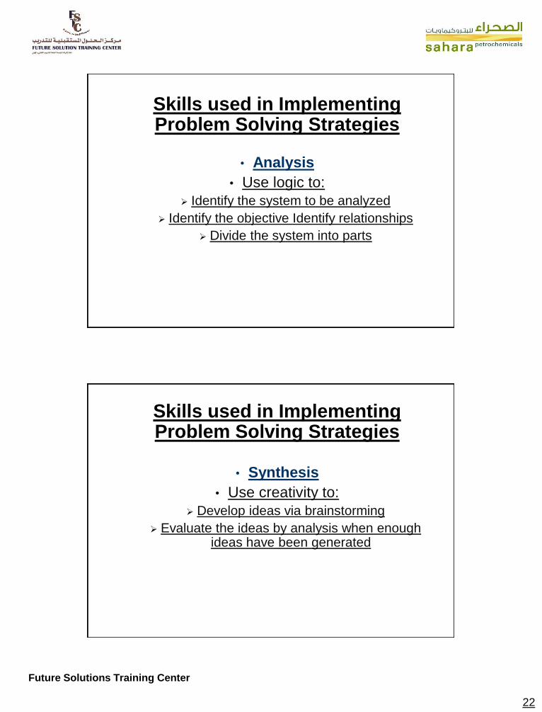
Skills used in Implementing Problem Solving Strategies
• Analysis
• Use logic to:
Identify the system to be analyzed
Identify the objective Identify relationships
Divide the system into parts
Skills used in Implementing Problem Solving Strategies
• Synthesis
• Use creativity to:
Develop ideas via brainstorming
Evaluate the ideas by analysis when enough ideas have been generated

Future Solutions Training Center
23
Skills used in Implementing Problem Solving Strategies
• Decision Making
• Use logic to
compare the various ideas and
select the ―best‖ one(s)
• Generalization - Going from the specific to the broad use abstraction to:
• Aid in analysis, synthesis, and decision making
Types of Problems
Research Problems
Knowledge Problems
Troubleshooting Problems
Mathematics Problems
Resource Problems
Social Problems
Design Problems

Future Solutions Training Center
24
Types of Problems; cont’
Research Problems
A hypothesis be proven or disproved
Example; CFC may destroy the earth‘s ozone layer is a hypothesis. Design an experiment
that either proves or disproves the hypothesis
Types of Problems; cont’ • Knowledge Problems
– When a person encounters a situation that he doesn’t understand
– Example;
– A chemical engineer noticed that the chemical plant produces more product when it rains
– Further study showed that heat exchanger cooled by rain increasing product

Future Solutions Training Center
25
Types of Problems; cont’ • Troubleshooting Problems
– When equipment or software behaves in unexpected or improper ways
– Example
– During vibration test of an aluminum beam, the amplitude of the response is higher at all exciting frequencies
– Troubleshooting shows that 60 cps of AC current was close to the natural frequency of the beam
Types of Problems; cont’
• Troubleshooting Problems; cont’
• e.g. an electronic amplifier has a loud “hum” when it is in a room with fluorescent lights.

Future Solutions Training Center
26
Types of Problems; cont’
• Mathematics Problems – Describe physical phenomena with mathematical
models
– Engineers can unleash the extraordinary power of mathematics, with the rigorously proven theorems and algorithms
– Example; Isaac Newton’s sine square law can be applied to hypersonic flow
– e.g. find x such that 4x + 5 = 0.
Types of Problems; cont’
Resource Problems
There is never enough time, money, or equipment to accomplish the task
Engineers who can get the job done in spite of resource limitations are highly prized and
awarded
e.g. how will we get the money to build our new factory?

Future Solutions Training Center
27
Types of Problems; cont’
Social Problems
For example, if a factory is relocated to where there is shortage of skilled worker, engineers should set up training program for employees
e.g. how can we improve education?
Types of Problems; cont’
Design Problems
Require creativity, teamwork, and broad knowledge
Example; design a new car
Economy car? SUV?
Design goal and parameters

Future Solutions Training Center
28
Difficulties in Problem Solving
Most common difficulty: failure to use known information.
To avoid this problem:
Write the problem in primitive form and sketch an accurate picture of
the setup (where applicable). Transform the primitive statements to simpler language.
Translate verbal problems to more abstract mathematical statement(s) and figures, diagrams, charts, etc.
General Problem Solving Method
Define and understand problem
1. Sketch the problem
2. Gather information
3. Generate and evaluate potential solutions Use applicable theories and assumptions
4. Refine and implement solution
5. Verify and test solution

Future Solutions Training Center
29
Define and Understand
Understand what is being asked
Describe input/output (I/O)
what are you given knowns
what are you trying to find unknowns
Sketch the problem
Gather Information
Collect necessary data
List relevant equations/theories
State all assumptions

Future Solutions Training Center
30
Generate Solution Methods
Apply theories and assumptions.
Typically, there is more than one approach to solving a problem
Work problem by hand using the potential solution methods
Break problem into parts; scale it down; etc. e.g., if the problem was to calculate the average of 1000 numbers, work the problem by hand using, say, 10 numbers, in order to establish a
method
Refine and Implement
Evaluate solution methods. accuracy
ease of implementation
etc.
Implement “best” solution.

Future Solutions Training Center
31
Verify and Test
Compare solution to the problem statement
Is this what you were looking for?
Does your answer make sense?
Clearly identify the solution
Sketch if appropriate
CHECK YOUR WORK!!
Don’t stop at getting an answer!! Think about whether the answer makes physical
sense. you are the instructor and you have to turn in final grades. In your haste, you calculate the average of Susie’s grades (100, 70, 90) to be 78
and give Susie a C...

Future Solutions Training Center
32
Getting It Right
• The problem solving process may be an iterative process.
• If at first you don’t succeed (i.e., the algorithm test fails), try again…
• The more thorough you are at each step of the problem solving process, the more likely you
are to get it right the first time!!
Creative Problem Solving
• Engineering is not dull or stifling; send people to moon, communication from battlefield, etc
• Creative artists spent many years perfecting their skills
• Engineers need patience, practice, and gaining problem-solving techniques by training

Future Solutions Training Center
33
Self-Questions for Problem Solving
• How important is the answer to a given problem?
• Would a rough, preliminary estimate be satisfactory or high degree accuracy demanded?
• How much time do you have and what resources are at your disposal?
– Data available or should be collected, equipments and personnel, etc
Self-Questions for Problem Solving
• What about the theory you intend to use? Can you use it now or must learn to use it? Is it state of the art?
• Can you make assumptions that simplify without sacrificing needed accuracy?
• Are other assumptions valid and applicable?
• Optimize time and resources vs reliability

Future Solutions Training Center
34
Engineering Method
1. Recognize and understand the problem (most difficult part)
2. Accumulate data and verify accuracy
3. Select the appropriate theory or principles
4. Make necessary assumptions
5. Solve the problem
6. Verify and check results
Engineering Method
• Perfect solutions to real problems do not exist. Simplify the problem to solve it; steady state, rigid body, adiabatic, isentropic, static etc
• To solve a problem, use mathematical model; direct methods, trial-and-error, graphic methods, etc.

Future Solutions Training Center
35
Problem Presentation
• Problem statement
• Diagram
• Theory
• Assumptions
• Solution steps
• Identify results and verify accuracy
Standards of Problem Presentation
• Engineers should have ability to present information with great clarity in a neat, careful manner
• Poor engineering documents can be legal problems in courts
• Follow standard forms such as shown in the textbooks

Future Solutions Training Center
36
Process Industries Challenges
• Maximize Production Output While Maintaining Product Quality
• Higher Operating Rates/Risks
• Increased Operator Scope of Responsibility
• Increased Safety Awareness
• Increased Usage of Sophisticated Plant Automation
Why Troubleshooting Matters to Operations Personnel
• Consequences of failure getting larger -->Cost, scale, EHS impact.
• Loss of experienced staff = loss of troubleshooting experts
• Well running plants provide for complacency, with few chances to keep troubleshooting skills sharpened

Future Solutions Training Center
37
What Have We Learned from Good Troubleshooters?
• Knowledge counts: Expertise in process leads to troubleshooting expertise
• Experienced troubleshooters keep getting called to help --> And so they maintain and improve their troubleshooting skills
• The best troubleshooters are systematic and “system thinkers.”
• Everybody wants them, but few have them
Successful Troubleshooting requires:
• An understanding of basic process parameters
• The ability to think in systems terms
• A systematic trouble-shooting methodology

Future Solutions Training Center
38
Formal Training Approaches
Most formal approaches to teaching troubleshooting skills fall into one of 2 categories:
Very generic
Equipment specific
These approaches have their limitations
Generic Approach to Troubleshooting
As taught in a leading plant safety seminar:
• Define the problem
• Gather relevant facts
• Identify the source of the problem
• Develop possible solutions
• Select the best solution

Future Solutions Training Center
39
Generic Approach
While this is certainly a respectable list of tasks, many people find it difficult to apply them across a broad range of problems.
Some examples specific to the trainee’s job would certainly help!
Often, though, the instructors for this type of training have little plant operations or maintenance experience.
Specific Troubleshooting Approach
• While this approach is on target for this particular problem, such as specific equipment operations, most people would have trouble generalizing the technique and applying it to other - particularly dissimilar - problems.

Future Solutions Training Center
40
“The Fundamentals of Process Troubleshooting”
Don Glaser, Simulation Solutions, and Paul Balmert, Balmert Consulting, have developed an effective approach to teaching troubleshooting skills for process operators.
Our approach embeds a sound generic troubleshooting model combined with immediate “hands on” practice.
This blend of knowledge and skills is unique to the industry.
The Fundamentals of Process Troubleshooting
Learning Objectives:
Describe the 5 Phases of effective trouble-shooting
Describe the specific Steps within each troubleshooting Phase
Successfully apply the Phases/ Steps to actual operations problems
Distinguish between “possible” and “probable causes”
Recognize the difference between “trial and error” & “designed testing”
Recognize the adverse effect of each of the following phenomena: ◦ Lock on/lock out
◦ Task interference
◦ Organization hierarchy
◦ Unintended consequences
Successfully counter the influence each of the above has on effective troubleshooting
Conduct the practice of trouble-shooting fully recognizing that safety -- process and personnel -- is always the first priority

Future Solutions Training Center
41
Troubleshooting
• Troubleshooting is something all technicians must do, but few truly master.
• In many cases, heat exchangers do not perform as expected and this can have a severe impact on plant operation.
• The troubleshooting process involves several phases of activity
Troubleshooting problems
• Troubleshooting problems with your heat exchangers is easy if you know what the signs and symptoms are telling you.
• Heat exchangers and heating or cooling coils are designed for the demands of corrosive chemical heating.
• A variety of standard configurations are available to suit specific process applications.
• In order to correctly diagnose problems, we must have a good understanding of the HEX and components that make up the overall system.

Future Solutions Training Center
42
Seven-step process • Use this seven-step process to be organized when
presented with a complex problem. • Seven-step process • Gathering (collecting) information • Understanding the malfunction • Identifying which parameters need to be evaluated • Identifying the source of the problem • Correcting/Repairing the component (s) • Verifying the repair • Performing root cause analysis
Site Investigations • Successful troubleshooting depends upon both the
quantity and quality of the information upon which the investigation is based.
• Good troubleshooter should attend the operating site in order to gather and verify the appropriate information.
• In addition to the collection of process data (temperatures, pressure etc.), more sophisticated techniques such as thermal imaging and radioisotope scanning can be applied.
Future Solutions Training Center
43
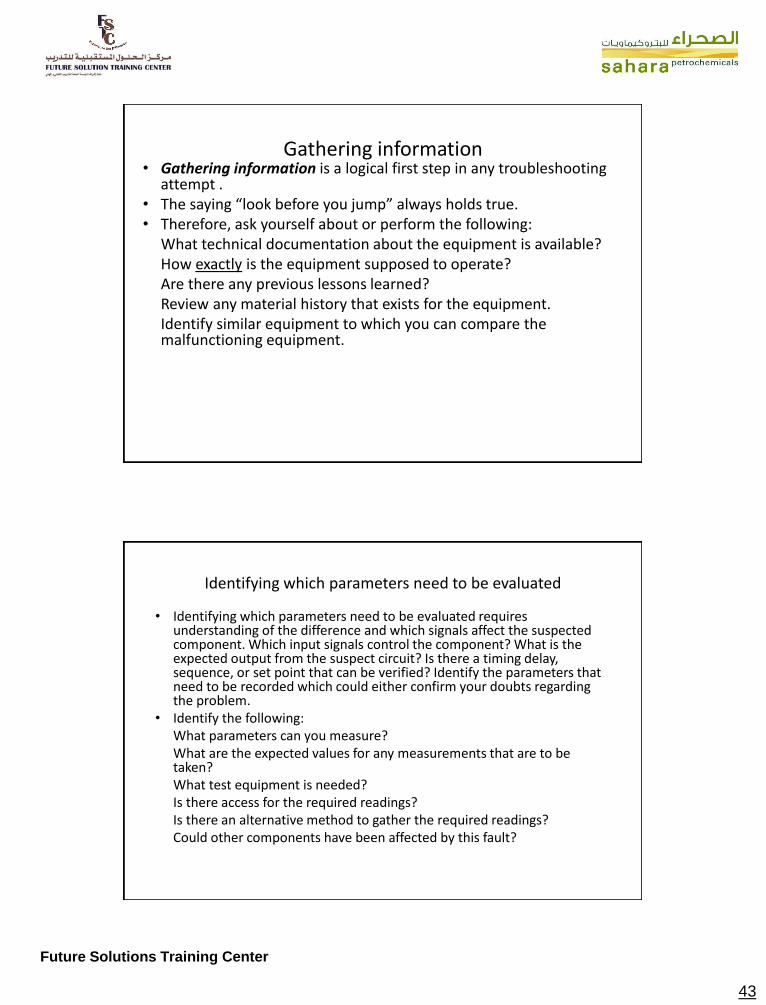
Gathering information • Gathering information is a logical first step in any troubleshooting
attempt . • The saying “look before you jump” always holds true. • Therefore, ask yourself about or perform the following: What technical documentation about the equipment is available? How exactly is the equipment supposed to operate? Are there any previous lessons learned? Review any material history that exists for the equipment. Identify similar equipment to which you can compare the
malfunctioning equipment.
Identifying which parameters need to be evaluated
• Identifying which parameters need to be evaluated requires understanding of the difference and which signals affect the suspected component. Which input signals control the component? What is the expected output from the suspect circuit? Is there a timing delay, sequence, or set point that can be verified? Identify the parameters that need to be recorded which could either confirm your doubts regarding the problem.
• Identify the following: What parameters can you measure? What are the expected values for any measurements that are to be
taken? What test equipment is needed? Is there access for the required readings? Is there an alternative method to gather the required readings? Could other components have been affected by this fault?

Future Solutions Training Center
44
Identifying the problem source
• Identifying the source of the problem requires the technician to:
Isolate components and evaluate circuit parameters.
Isolate the circuit by group when dealing with a complicated circuit (half step approach).
Identify the malfunctioning component using the recorded data.
Correcting/Repairing
• Correcting/Repairing the component identified as damaged based on the recorded data.
• Perform the required repairs to the circuit.
• Completing this step can range from simple adjustments to a complete component replacement.

Future Solutions Training Center
45
Repair Verifying
• Verifying the repair after completion. Ensure the equipment is operating as designed.
• Perform another round of testing to verify the equipment is in fact running correctly and that no other disagreement exist.
Corrective Action
• Once the true nature of the heat exchanger operation has been discovered, the way is clear to develop proposals for corrective action.
• In many cases operational changes will be sufficient to restore proper operation.

Future Solutions Training Center
46
Root cause analysis • Performing root cause analysis began in the first step of the
troubleshooting process. • Use the knowledge gained throughout the troubleshooting
process in determining what could have possibly caused the component to fail.
• Did the component fails early? • Why are the motor windings failing after only four years of
service? These are just a few of the questions that may come to light when evaluating the whole repair process.
• Without identifying the possible cause that led to the failure, the repair will always be only temporary.
• While working through the troubleshooting process, ask yourself, “Is this the root cause or just a warring sign of the problem?”
Fault-Logic Troubleshooting
• This a diagnostic aid for the operator to locate possible HEXs problems.
• Following the fault-logic diagrams are diagram action comments to further help explain the action steps shown in the diagrams.

Future Solutions Training Center
47
• Neutral Difficult or Impossible to Find
Boilers and Heat Exchangers Troubleshooting

Future Solutions Training Center
48
Boiler Troubleshooting
• In the next discussion of operational troubles, we have taken up boiler operating troubles by starting with a generally observable symptom and checking through a number of possible causes.
• As you will probably noticed, the same cause is frequently given for several quite different operational symptoms or difficulties.
• As you will notice, the signs or difficulties are in some cases mutually excusive.
• For example, a leaky desuperheater can cause low superheater outlet temperature or high superheater the same time.
• In other cases, several signs may exist at the same time as the result of one cause.
Boiler Troubleshooting

Future Solutions Training Center
49
Maintenance and Cleaning:
Boiler Troubleshooting

Future Solutions Training Center
50
Boiler Troubleshooting
Boiler Troubleshooting

Future Solutions Training Center
51
Boiler Troubleshooting

Future Solutions Training Center
52
Boiler Troubleshooting

Future Solutions Training Center
53

Future Solutions Training Center
54
Boiler Troubleshooting

Future Solutions Training Center
55
Boiler Troubleshooting
• Burner cuts on and off continuously
• This could be caused by:
1. Faulty pressure switch
2. Insufficient Load
• Improper combustion
• This could be caused by:
1. Incorrect air/fuel ratio
2. Dirty boiler internals
3. Oil temperatures
4. Defective refractory
5. Carbon build up on burner combustion head
6. Change in fuel supply conditions
7. Damaged combustion head

Future Solutions Training Center
56
Boiler Troubleshooting
• Other boiler problems causing Burner lockout
• This could be caused by:
1. Boiler at extra low water
2. Boiler at excess pressure or temperature
3. High or low gas pressure
Superheater outlet thermometer indicates excessively high superheater
• Too much excess air. • Low feed water temperature. • Incorrect burner sequence. • Mixed sprayer plates. • Incorrect impeller position. • Too much oil being fired. • Oil too viscous. • Faulty instruments. • Plant not lined up properly.
• Back flow of steam through desuperheater.
• Dirty generating surfaces. • Too many water screen tubes
plugged. • Dirty economizer. • Leaky desuperheater. • Too many superheater tubes
installed. • Water screen tube baffles too
long.

Future Solutions Training Center
57
Carryover Possible Causes:
• High water
• Boiler water contamination
• Defects in steam drum internals
Stack gas temperature unusually high.
• Possible Causes
• Too much excess air
• Secondary combustion in gas passages
• Dirty firesides or dirty watersides
Boiler Troubleshooting
Boiler Troubleshooting
Low steam pressure : Possible Causes Low water Excessive steam demands Poor combustion Faulty instruments High feed water consumption: Possible Causes Failure to shift drains from safety valves Small leak in boiler tube Cracked welds at superheater tube seats Economizer leakage Superheater hand hole leakage Water drum and header handhold leakage Defects in auxiliary
machinery Steam or water leakage

Future Solutions Training Center
58
Boiler Troubleshooting
Inability to maintain prescribed alkalinity, phosphate, or DH levels despite excessive use of boiler compound or other water-treatment chemicals.
Possible Causes
• Failure to remove preservatives
• Feed water contamination
• Leaky desuperheater
• Leaky boiler tube
• Other steam or water leakage
Boiler Troubleshooting
• Dissolved oxygen in feed water or boiler water. Possible Causes:
• Failure to lay up idle boilers correctly incorrect operation of deaeratinq feed tank Defects in deaerating feed tank
Oil in deaerating feed tank or boiler. Possible Causes
• Lubricating oil leakage.
• Fuel oil leakage.

Future Solutions Training Center
59
Boiler Troubleshooting
• Combustion gases entering fireroom
• Possible Causes
• Inner casing leakage
• Leakage through soot blower casing seal
• Leakage through economizer drain lines
Boiler Troubleshooting Oil impingement on furnace walls and tubes or on impeller plates; carbon
or soot deposits on walls, tubes, water drum, or burner parts. Possible Causes: • Incorrect viscosity, temperature, or pressure of fuel oil. • Incorrect relationship between air pressure and sprayer plates. • Incorrect impeller position • Improperly made up atomizer assemblies. • Defective sprayer plates or nozzles. • Water in fuel oil. Burner misalignment • Loose or partly closed air doors Incorrect setting of distance piece. • Defects of burner cone openings Incorrect setting of soot blower cams. • Failure to withdraw atomizer

Future Solutions Training Center
60
High fuel oil consumption
Sudden changes in steam demand.
Too much or too little excess air.
Incorrect relationship between air pressure and sprayer plates.
Low fuel oil pressure. Cold fuel oil. Burner defects. Dirty firesides and dirty
watersides.
Low feed water temperature.
Water in fuel oil.
Steam or fresh water leakage.
Leaky casings.
Use of too many auxiliaries.
Fuel oil leakage.
Excessive feed water pressure.
Damaged refractories.
Defects in auxiliary machinery.
Boiler Troubleshooting
• Overheated superheater, with or without rise in superheater outlet temperature (single- furnace boiler).
• Possible Causes • Insufficient steam flow. • Sudden decrease in steam demand. Too much excess air. • Dirty superheater surfaces. • Leaky desuperheater. • Warped water screen tubes. • Eroded water screen tube baffles.

Future Solutions Training Center
61
Boiler Troubleshooting
Overheated superheater, with or without rise in superheater outlet temperature (double-furnace boiler).
• POSSIBLE CAUSES
• Insufficient steam flow.
• Sudden decrease in superheated steam demand.
• Sudden excessive demand for auxiliary steam.
• Too much excess air.
• Overfiring saturated side.
• Dirty superheater surfaces.
• Eroded water screen tube baffles.
• Warped water screen tubes.
Steam Trap - Troubleshooting
• It is important to inspect the operation of steam traps frequently. There are many conditions under which traps may fail to operate property. The following are some of the most common reasons for trap failures:

Future Solutions Training Center
62
Steam Trap - Troubleshooting
1. Condensate does not flow into the trap:
a. Obstruction in line to trap inlet. b. Valves leading to trap are closed. c. Bypass open or leaking. d. Trap may be air bound. e. Insufficient pressure to blow
condensate through orifice. f. Improper installation of trap. g. Accumulation of foreign matter within
the trap. h. Trap held closed by defective
mechanism. i. Strainer may be blocked.
2-Condensate fails to drain from trap.
a. Discharge valve may be closed. b. Trap may not be large enough to
handle condensate. c. Pressure may be too low to blow
the condensate through. d. Improper installation for draining. e. Check valve may not be holding. e. Obstruction in return line or the line
may simply be too small.
Steam Trap - Troubleshooting
3- Trap does not shut off. a. Trap is too small for the
condensate load. b. Trap held open by defective
mechanism, c. Overload due to excessive boiler
foaming or priming. d. Submerged steam coils leaking. e. Differential pressure exceeds
design of trap. f. Scale or foreign matter lodged in
orifice.
4. Steam blows through trap. a. Valve mechanism does not close
due to wear or defective valve. b. Mechanism is held open by
foreign matter. c. Trap has not been properly
primed or re-primed after clean-out or blow-off.
d. Bypass is open or leaking. e. Excessive pressure for design of
trap.

Future Solutions Training Center
63
Deaarator Troubleshooting
Tube Inspections Eddy Current -Ultrasonic -Visual Remote Visual
• Tube Testing -Hydrostatic -Pneumatic -Vacuum
• Tube Cleaning -
Rotating Brush -Projectile Brush -Projectile Scraper -Hydro blasting
• Tube Sleeving -In let -Outlet -Full Length
• Tube Plugging -Near End - Through-the tube

Future Solutions Training Center
64
Heat Exchangers Troubleshooting
• In the next discussion of operational troubles, we have taken up HEX operating troubles by starting with a generally observable Problem (Sign) and checking through a number of possible causes.
• As you will probably noticed, the same cause is frequently given for several quite different operational Problems or difficulties.
• As you will notice, the signs or difficulties are in some cases mutually excusive.
• For example, a leaky desuperheater can cause low superheater outlet temperature or high superheater outlet temperature the same time.
• In other cases, several signs may exist at the same time as the result of one cause.
Air to Air and Air to Fluid Heat Exchanger Troubleshooting Chart
Air to Air and Air to Fluid Heat Exchanger Troubleshooting Chart
Symptom Potential Cause Possible Solution
Heat exchanger fan is drawing too many amps
Look in the trouble shooting for motors
Fan blade pitch and diameter may be wrong
Change fan blade
Motor may be operating at wrong RPM for fan blade
Replacae motor or fan blade
Check clearance of fan blade
Make adjustments if blade is hitting things

Future Solutions Training Center
65
PHE Troubleshooting
Problem Possible cause Possible solution
Leakage
At the connections
-Check the rubber liners (if fitted)
-Check the flange packing (if fitted)
-Check the 0-ring on the first plate
-Fit the pipes tension-free
Mixing of primary and
secondary circuit
- Check the plates for holes and/or
cracks
In plate package
-Check the assembly distance
-Check the condition of the packings
-Check the proper position of the
packings
The operating conditions
deviate from the
specification
- Adjust the operating conditions
• For nearly all leakage problems it will be necessary to dismantle the unit before any attempts to rectify the fault can be made.
• Mark the area (s) where the leakage seems to be with a felt tip marker or similar before taking apart the exchanger.
• “Cold leakage” is caused by a sudden change in temperature.
• The sealing properties of certain elastomers are temporarily reduced when the temperature changes suddenly.
• No action is required as the gaskets should re-seal after the temperature has stabilized.

Future Solutions Training Center
66
PHE Troubleshooting
Problem Possible cause Possible solution
Insufficient
capacity
Air in the system
- De-aerate the pipe
system
- Check the pipe work
for possible air traps
The operating conditions
deviate from the
specification
- Adjust the operating
conditions
The heat exchanger is
dirty
- Clean the heat
exchanger
The connections have
been interchanged - Redo the filling work
PHE Troubleshooting
Problem Possible cause Possible solution
Too high
Pressure
drop
Flow larger than the
design flow - Adjust the flow
Channels in plate(s)
blocked - Flush /clean
Incorrect measurement - Check the pressure indicator
Medium deviating from
the design
- Addition of for instance anti-
freeze will increase the pressure
drop
Air in the system
- De-aerate the pipe system
- Check the pipe work for
possible air traps

Future Solutions Training Center
67
HEX Troubleshooting
Problem Probable Cause Remedy
No liquid
delivered.
1. Pump not primed.
2. Discharge valve closed.
3. Suction line clogged.
4. Wrong direction of
rotation.
5. Total head is too high.
6. Driver is not operating
at rated speed.
7. Pump is vapor bound
8. Foot valve or suction
pipe opening not
submerged enough.
9. Suction lift too high.
1. Reprime pump, check that pump and
suction line are full of liquid.
2. Check discharge valve.
3. Remove obstructions.
4. Change rotation to concur with
direction indicated on bearing
housing or pump casing.
5. Re-evaluate head conditions.
6. Check electric motor voltage;
check engine rpm
7. Provide additional pressure on
liquid being pumped by elevating
liquid source.
8. Consult factory for proper depth.
Use baffler to eliminate vortices.
9. Shorten suction pipe.
Pump not producing rated flow or head.
1. Air leak through gasket. 2. Air leak through stuffing box. 3. Impeller partly clogged. 4. Worn suction side plate or wear rings. 5. Pump is not properly primed. 6. Suction lift is too high. 7. Driver is not operating at rated speed. 8. Pump is vapor bound 9. Insufficient suction head. 10. Worn or broken impeller.
1. Replace gasket. 2. Replace or adjust packing/mechanical seal. 3. Back flush pump to clean impeller. 4. Replace defective parts as required. 5. Reprime pump, check that pump and suction line are full of liquid. 6. Shorten suction pipe. 7. Check electric motor voltage;check engine rpm 8. Provide additional pressure on liquid being pumped by elevating liquid source. 9. Ensure that suction line shutoff valve is fully open and line is unobstructed. 10. Inspect and replace if necessary.

Future Solutions Training Center
68
Problem Probable Cause Remedy
Pump starts then stops pumping. Bearings run hot.
1. Improperly primed pump 2. Excessive air in liquid. 3. Suction lift too high. 4. Defective packing or seal. 5. Pump is vapor bound. 6. Air or vapor pockets in suction line. 7. Air leak in suction line. 1. Improper alignment. 2. Improper lubrication. 3. Lube cooling.
1. Reprime pump. 2. Clean and tighten all suction connections; relocate suction inlet in liquid source. 3. Re-evaluate pump requirements and correct suction conditions. 4. Replace packing or seal. 5. Provide additional pressure on liquid being pumped by elevating liquid source. 6. Rearrange piping to eliminate air pockets. 7. Repair leak. 1. Re-align pump and drive. 2. Check lubricate for suitability and level. 3. Check cooling system.
Problem Probable Cause Remedy
Pump is
noisy or
vibrates.
1. Improper pump/driver
alignment.
2. Partly clogged
impeller causing
imbalance.
3. Broken or bent
impeller or shaft.
4. Foundation not rigid.
5. Worn bearings.
6. Suction or discharge
piping not anchored or
properly supported.
7. Pump is cavitating.
1-Align shafts.
2. Back-flush pump to
clean impeller.
3. Replace as required.
4. Tighten bolts of pump
and motor or adjust stilts.
5. Replace.
6. Anchor per Hydraulic
Institute Standards
Manual recommendation.
7. System problem.

Future Solutions Training Center
69
Problem Probable Cause Remedy
Excessive
leakage
from
stuffing
box/seal
chamber.
1. Packing gland
improperly
adjusted.
2. Stuffing box
improperly packed.
3. Worn mechanical
seals.
4. Overheating
mechanical seal.
5. Shaft sleeve
scored.
1. Tighten gland
nuts.
2. Check packing
and repack box.
3. Replace worn
parts.
4. Check
lubrication and
cooling lines.
5. Remachine or
replace as
required.
Problem Probable Cause Remedy
Motor
requires
excessive
power.
1. Head lower than rating;
pumps too much liquid,
2. Speed is too high.
3. Wrong direction of
rotation.
4. Impeller is clogged.
5. Impeller is binding.
6. Driver and pump are
misaligned.
7. Power frame shaft is
bent.
8. Worn suction side plate
or wear rings.
9. Liquid heavier than
expected.
10. Stuffing box too tight.
11. Rotating parts bind.
1. Consult factory. Install throttle valve,
trim impeller diameter.
2. Electric motor wiring is wrong.
Replace motor.
3. Check wiring diagram.
4. Back flush pump to clean impeller.
5. Relieve strain on casing; adjust
impeller clearance.
6. Realign driver with pump.
7. Replace shaft.
8. Replace defective parts as required.
9. Check specific gravity and viscosity.
10. Readjust packing. Replace if worn.
11. Check internal wearing parts for
proper clearances.

Future Solutions Training Center
70
Problem Probable Cause Remedy
Pump fails to
prime or
loses its
prime,
Insufficient
pressure.
1. Air leaks in suction line.
2. Suction strainer is
clogged. Suction lift is too
high.
3. Defective priming valve.
4. Defective packing or
seal.
5. Self-Priming Pump 1. Excessive air in liquid.
2. Driver is not operating at
rated speed.
3. Wrong direction of
rotation.
4. Total head is too high.
5. Worn suction side plate
or wear rings.
6. Broken or bent impeller
or shaft.
7. Air leak through gasket.
8. Liquid is vaporizing
1. Clean and tighten all suction connections;
relocate suction inlet in liquid source.
2. Clean debris from strainer. Re-evaluate pump
requirements and correct suction conditions.
3. Replace valve.
4. Replace packing or seal.
5. Fill pump housing with liquid. Open the
discharge gate valves to evacuate air.
1. Clean and tighten all suction connections;
relocate suction inlet in liquid source.
2. Check electric motor voltage; check engine
rpm
3. Change rotation to concur with direction
indicated on bearing housing or pump casing.
4. Re-evaluate head conditions.
5. Replace defective parts as required.
6. Replace as required.
7. Replace gasket.
8. Provide additional pressure on liquid being
pumped by elevating liquid source.
Air to Air and Air to Fluid Heat Exchanger Troubleshooting Chart
Problem Potential Cause Possible Solution
Heat exchanger fan is drawing too many Current (amps)
Look in the trouble shooting for motors
Fan blade pitch and diameter may be wrong
Change fan blade
Motor may be operating at wrong RPM for fan blade
Replace motor or fan blade
Check clearance of fan blade
Make adjustments if blade is hitting thin

Future Solutions Training Center
71
Belt Driven Assemblies Troubleshooting
Problem Potential Cause Possible Solution
Squealing noise occurs on startup
Belt is too loose. Check tension of belt and tighten if required.
Excessive wear on bearings
Belt is too tight. Loosen belt tension.
Belt is wearing excessively
Check orientation of blower and motor.
Adjust orientation if required.
Centrifugal Pump Troubleshooting Chart
Problem Potential Cause Possible Solution
Pump does
not produce
sufficient
pressure/
vacuum
Pump is not primed Prime pump
Wrong direction of rotation Check and change rotation if
required
Vacuum or Pressure gauge is faulty Replace gauge.
Pump is not operating at required
RPM
Check and replace motor if
required
Pump has wrong sized impeller Check impeller and replace if
required
Pump pressure or vacuum is lost due
to obstruction located between pump
and gauge
Check for flow restrictions and
clean strainers or piping if
required
Pump is not turned on Ensure pump is turned on
Coupling between pump and motor is
no longer connected preventing the
pump from rotating with the motor
Reconnect and realign motor
and pump

Future Solutions Training Center
72
Centrifugal Pump Troubleshooting Cont’d
Pump is leaking Gaskets are worn or faulty
Replace gaskets
Mechanical seal has been overheated, often as a result of operating the pump without any water
Replace mechanical seal
Fittings are leaking on or around pump
Tighten fittings
Water may be coming from another location
Check for leaks around pump
Centrifugal Pump Troubleshooting Pump flow rate
is too low Back pressure is too
high for pump Reduce back
pressure
Pump may not be sized correctly for process
Replace pump
Pump impeller is too small
Change pump impeller but watch power consumption on motor
Flow control valve is closed
Open flow control valve
May have blocked line or filter
Replace filter and clean line

Future Solutions Training Center
73
Centrifugal Pump Troubleshooting
Pump is making excessive noise during operation
Manually rotate pump impeller and listen for clearance problems
Disassemble pump and fix clearance problems.
Alignment of pump may be off causing the flexible coupling to degrade
Check alignment and reset alignment if it is a problem. Replace flexible coupling if it is degraded
Electric Solenoid Valve Troubleshooting Chart
Problem Potential Cause Possible Solution
Valve will not completely shut
May have dirt or scales preventing it from shutting properly
Disassemble and clean out internal components
Valve will not open
Check for power to solenoid
Trace power lines and determine why power is not going to valve
PLC may not be telling solenoid to open
Check start requirements in manual
Coil may be damaged or faulty
Replace coil

Future Solutions Training Center
74
Level Switch Troubleshooting Chart Problem Potential Cause Possible Solution
Level switch is staying closed when water in tank drops below switch
Level switch is upside down or on its side
Check orientation of level switch. Level switch may be designed as normally closed and therefore will be upside down
Sight glass is plugged giving a false level in the tank
Clean sight glass
Level switch has dirt or film causing it to stick up
Remove level switch, clean and test for normal operation using a millimeter
Level switch may be damaged or faulty and failed closed regardless of the switch position
Replace switch
Symptom Potential Cause Possible Solution
Level switch stays open when water in tank is above the switch
Level switch is upside down or on its side
Check orientation of level switch. Level switch may be designed as normally closed and therefore will be upside down
Sight glass is plugged giving a false level in the tank
Clean sight glass
Level switch has dirt or film causing it to stick down
Remove level switch, clean and test for normal operation using a millimeter
Level switch may be damaged or faulty and failed open regardless of the switch position
Replace switch
IS barrier is blown preventing the level switch signal from crossing the barrier
Switch IS barrier with working barrier and if problem goes away then the barrier may be blown. If barrier is blown then the input wire on the right side of the barrier will have 24 V DC and the wire on the opposite side will have 0V DC.
Level switch is wired incorrectly
Consult input wiring diagram and inspect wiring of level switch. Change if required.

Future Solutions Training Center
75
Pressure Switch Troubleshooting Chart
Symptom Potential Cause
Possible Solution
Switch is not reacting at desired set point
Switch is out of adjustment
Change set point to desired value
Switch is not working
Switch may be faulty
Remove input wires and test switch at desired pressure. If it does not trigger then it should be replaced
Flow Meter Troubleshooting Chart
Symptom Potential Cause Possible Solution
Flow meter is not rotating
Dirt could have caused meter internals to jam
Disassemble flow meter and clean internal components
Flow meter is rotating but pulse input is not working
Switch on meter may be faulty
Remove wiring and test contacts on meter to ensure that they are opening and closing. If not then meter head needs to be replaced
Input wiring may be grounding out preventing the signal from opening and closing
Test input wiring by isolating input wires and checking if input is on. If so then you have a grounded input wire
Input to PLC is not working Simulate rotating meter by contacting input wires together and check for a detected flow rate and change in totalized flow

Future Solutions Training Center
76
Regenerative Blower Troubleshooting Chart Symptom Potential Cause Possible Solution
Blower does not produce sufficient pressure/vacu
um
Blower is not turned on Turn on blower
Wrong direction of rotation Check and change rotation if required
Vacuum or Pressure gauge is faulty Replace gauge
Blower is not operating at required RPM Check and replace motor if required
Blower has wrong sized impeller Check impeller and replace if required
Pressure or vacuum is lost due to obstruction located between blower and gauge
Check for flow restrictions and clean strainers or piping if required
Blower is leaking Fittings are leaking on or around blower Tighten fittings
Blower flow rate is too low
Back pressure is too high for blower Reduce back pressure.
Blower may not be sized correctly for process
Replace blower
Blower impeller is too small Change blower impeller but watch power consumption on motor
Flow control valve is closed Open flow control valve
May have blocked line or filter Replace filter and clean line
Possible
Solution
Potential Cause Problem
Vent Air in cooling system due to incorrect system fill
Combustion gases in cooling system
Steam in system due to overload or low level
Coolant Overflow
Stuck thermostat
Absence of thermostat
Low engine speed — High idle
Loose or eroded water pump impeller
Radiator plugged internally
Insufficient Coolant
Flow
High ambient air temperature
Plugged openings in screens for engine compartment
with a blower/ fan
Dirty aftercooler core
Plugged air cleaner
Damaged or carbon packed turbocharger
High Intake Air
Temperature or
Restriction
Insufficient flow through heat exchanger
Hot air for radiator due to overheating hydraulic oil
cooler
Scale on cylinder liners or cylinder head
High ambient air temperatures with a marginally sized
radiator
Low Heat Transfer
Engine Cooler troubleshooting

Future Solutions Training Center
77
Make sure the compressor is not in direct contact with the base
or sides of the cabinet (‗old surroundings can cause liquid
slugging. increase ambient temperature
Compressor Noisy
Operation
Clattering or humming noise in the contactor could be due to
control voltage less than 18 volts. Check for supply voltage.
low transformer output or extra long runs of thermostat
wires. If the contactor contacts are pitied or corroded or coil
is defected. Repair or replace.
Contactor
Check for loose screws, panels, or internal components. Tighten
and secure. Copper piping could be hitting the metal
surfaces. Careful readjust b bending slightly
Rattles and
Vibrations
Undersized ductwork will cause high airflow velocities and noise
operation. Excessive water through the water-cooled heat
exchanger will cause a squealing sound. Check the water
f1ow ensuring adequate flow for good operation but
eliminating the nose.
Water and
Airborne noise
Purge air from closed loop system Cavitation Pumps
Remedy Cause Fault
clean the HE plates deposits on the HE plates insufficient
heat
transfer have GEA Ecoflex examine the
design of the PHE with
thenew operating data
flow paths, media etc.
changed from the
design
clean the HE plates flow impeded by blockage
of
the flow channels of the
distributor
check the installation order by
means of the flow diagram
flow impeded by incorrect
installation of the HE
plates
have GEA Ecoflex examine the
design of the PHE with the
new operating data
flow paths, media etc.
changed
from the design

Future Solutions Training Center
78
Remedy Cause Fault
check the correct compression
dimension by means of the
data on the name plate
false
compression
dimension
of the PHE
sealing fault
between
the HE
plates
check the working pressures
by means of the data on the
name plate
too high working
pressures
check the working temperatures
by means of the data on
the name plate
too high/too low
working
temperatures
open the PHE and correct the
gaskets‘ position
gaskets fitted
incorrectly
open the PHE and clean the
gaskets
gaskets are dirty
open the PHE and replace the
gaskets
gaskets are
defective
Remedy Cause Fault
open the PHE, correct the
position of the gaskets or port
rings
gaskets or port rings fitted in-
correctly
sealing fault
between
plates and frame,
intermediate
plates,
intermediate
elements
open the PHE, clean the gaskets
or port rings
gaskets or port rings are
dirty
open the PHE, replace the
gaskets or port rings
gaskets or port rings are
defective
reduce connection loads to
the admissible parameters
too high loads at the pipe
connection due to the pipe
sealing fault
between pipe
connection and
frame plate loosen the pipe connection
and correct the position of the
seal ring
seal ring fitted incorrectly
loosen the pipe connection
and clean the seal ring
seal ring is dirty
loosen the pipe joint and re
place the seal ring
seal ring is defective
check the seal ring and
connection and tighten any loose
bolts
flange connection is not
sufficiently-tightened

Future Solutions Training Center
79
Problem Recommend Solution
Unit will not start
• Check the line cord; make sure it is
plugged in.
• Check the voltage on the power source.
Make sure it is within the rated voltage of
the unit ± 10%.
• Check that the Power Switch is on and
that the fuses have not blown.
Unit will not
circulate fluid
Check the reservoir level. Fill, if necessary.
Check for blockage.
Fan capacity or pressure is below rating:
1. Dampers or variable inlet vanes are not adjusted properly 2. Fan inlet or outlet conditions are impaired 3. Multiple air leaks within the system 4. Damage sustained to the blower wheel 5. Direction of rotation is incorrect

Future Solutions Training Center
80
Fan vibrates or makes noise
1. Worn bearings 2. Unstable foundation 3. Foreign material in the fan causing an imbalance 4. Misalignment of bearings, couplings, wheel or v-belt drive 5. Damaged wheel or motor 6. Bent shaft 7. Worn coupling 8. Loose dampers or variable inlet vanes 9. Speed too high or incorrect fan rotation 10. Vibration to fan transmitted from another source 11. Uneven blade wear 12. Loose or broken bolts or set screws
Overheated Bearings:
• 1. Improper lubrication 2. Poor alignment 3. Damaged wheel or driver 4. Bent shaft 5. Abnormal end thrust 6. Dirt in bearings 7. Improper belt tension

Future Solutions Training Center
81
Overload on Driver:
• 1. Speed too high 2. Direction of rotation is incorrect 3. Bent shaft 4. Poor alignment 5. Improper lubrication 6. Wheel wedging or binding on fan housing
HEATERS Troubleshooting chart
• Element will not heat properl 1) No power/electrical fusing.
2) Open/overheated thermal fuses on heater.
3) Missing thermal fuse.
4) Thermostat not turning heater on (new installations).
5) Thermal fuse (s) keep opening.
6) Protector II bimetallic thermostats opening at a low temperature.
7) Heater blowing electrical fuses.
8) Reduced output of heater.
9) Voltage measured in tank.

Future Solutions Training Center
82
HEX NOT HEAT PROPERLY
1) Supply problems, no steam/hot water.
SOLUTION CAUSE
Verify that all valves preceding coil are
open and supply is available to coil.
Steam/hot water source is blocked
by shut off valves.
Open and clean strainer. Plugged strainer.
Repair or replace trap. Defective trap or mis-sized trap.
Connect as required. Solenoid valve not connected to
terminal blocks in control.
Replace solenoid valve or coil to match
available power.
Solenoid coil voltage does not
match power supply.
Verify thermostat settings and switch
operation, repair or replace as required. Incorrect thermostat settings.
Verify temperature control operation,
repair or replace as required.
Defective temperature
control/sensor.
2) Valve not turning on.
SOLUTION CAUSE
Test operator coil by applying rated voltage and replace coil or valve as required.
Solenoid valve electric operator coil open/burned out.
Clean/repair valve if possible. Install strainer on inlet supply prior to valve to reduce particulate matter flowing through valve.
Solenoid valve stuck in closed position by deposits.
Increase pressure on supply or replace valve with a zero pressure drop model valve.
Low pressure. (Many pilot operated solenoid valves require 5 PSIG minimum pressure drop across valve to operate.)
Verify valve operation and replace as required.
N/O (Normally Opened) solenoid valve used instead of N/C valve.

Future Solutions Training Center
83
3) Reduced output of HEX.
Any time reduced output of a HEX is suspected, tests should be peincoming rformed to measure the pressure and temperature of the source and amount of condensate or temperature of output water.
SOLUTION CAUSE
Measure the available pressure and compare it to the rating on the tag. Check and compare your incoming pressure at the boiler vs. the pressure at the coil. If the difference exceeds 3 psi consider increasing the pipe size or adding insulation. Either add additional coils or replace the coil with a larger one to add more exchanger surface area to increase capacity.
Low steam pressure. (Any pressure below the design rating of the HEX significantly reduces the rated output of the exchanger.)
3) Reduced output of coil Cont’d
Place/secure sensor 1/3 of way down in solution (preferably within a thermal well).
Temperature control sensor not located properly in tank.
Increase steam pressure at the valve or install a direct acting or zero pressure differential valve in its place.
Steam pressure too low for proper operation of standard pilot operated valve..
Reconnect coils in parallel to an appropriately sized header.
Coils plumbed in series. (This condition would cause each successive coil to produce less than the rated output while increasing the pressure drop and condensate on the system substantially.)
Contact factory for repair install drip trap before steam valve and water hammer arresters in supply line.
Water hammer damage to internal baffles within grid style coils which allows flow to bypass portions of the exchanger.

Future Solutions Training Center
84
3) Reduced output of coil Cont’d
Inspect and clean coils on a regular basis appropriate to the rate of buildup from the chemistry employed. Check application, as larger/more surface area may be required in most solutions that buildup quickly.
Buildup on coil case.
Verify heat requirements and replace exchanger as required.
Improperly sized exchanger.
Fill tank to submerse coil or correct mounting or plumbing to accommodate low fluid level.
Coil not fully submersed in fluid being heated.
Verify inlet/outlet per installation instructions and correct connections as required.
Inlet/outlet connections reversed on steam coil.
Verify temperature of feed water and correct as required.
Low temperature feed water supply (for heating). Too high temperature feed water supply for cooling.
Reduced output of coil Cont’d
Reconnect stream trap on outlet side of coil. Steam trap installed on inlet side of coil.
Clean any deposits from trap vent. Plugged vent hole on steam trap.
Clean or replace strainer. Blocked strainer.
Calculate BTU requirements for tank and corresponding rating for pipe at your system steam or water temperature and replace as required.
Undersized supply piping.
Calculate BTU requirements for tanks and respective flow requirements. Rework or replace coil inlet/outlet tubes to accommodate flow.
Undersized inlet/outlet supply tubes to coil.
Replace coil with one designed for water service.
Steam coil operated on water service. Grid style water coils require baffles to direct internal flow. (Note: Coils designed for water service will operate fine in both steam or water applications.)

Future Solutions Training Center
85
3) Reduced output of coil Cont’d
Reduce or remove pipe insulation if trap is mounted in a protected area or replace trap with a style that does not rely on external cooling to operate.
Insulation on trap. Too much insulation on steam trap can reduce cooling rates on thermostatic traps and impede their operation.
Verify that pressure on condensate leg is below pressure on outlet of each individual coil.
Back pressure from condensate return on low-pressure steam systems can prevent outflow of condensate from trap.
Do not route condensate return above outlet of exchanger without condensate pump. Trap should be mounted 18" below coil outlet. Correct trap location and condensate piping as required.
Condensate return line and/or trap above exchanger.
Re-plumb trap 18" below exchanger outlet line with as short of horizontal pipe as possible. If problem persists, install steam lock release or trap with integral steam lock release.
Steam lock on piping between coil and trap.
Calculate BTU requirement for tank and verify proper trap sizing. Replace as required.
Improperly sized trap.
3) Reduced output of coil Cont’d
Each coil must have its own trap for proper operation. Verify operating parameters for each coil and install an appropriately sized trap.
Multiple coils on single steam trap.
Evaluate BTU requirement for tank and verify valve Cv rating. Replace valve as required.
Improperly sized solenoid valve.
Inverted bucket traps work fine on metal coils, however, balanced pressure or thermostatic traps perform better on the exchangers by reducing air binding. Replace traps as required on HEX coils.
Improper trap style selection.
Re-plumb condensate return system or add condensate sump/pump to evacuate condensate.
Condensate line plumbed above exchanger causing back pressure on trap.

Future Solutions Training Center
86
3) Reduced output of coil Cont’d
Change trap style to one that can vent air from system faster or install a bypass bleed valve to evacuate air in line.
Air-bound steam trap. Air in system both insulates and dilutes the steam reducing its temperature and forms a film on the exchanger walls limiting heat transfer.
Multiple coils should be plumbed to a single appropriately sized header and with valves provided to distribute/adjust each output. Combining water coils of different sizes, or non-uniform groupings will cause unbalanced pressure drops on one or more of the coils and inefficiencies.
Unbalanced load/mixed types of coils.
Dissolve away all deposits with exchanger with a chemically compatible cleaner. Install a water conditioner and strainer on the water/steam supply.
Buildup inside exchanger sheath. Caused by particulates or colloidal materials that have accumulated on the coil interior surfaces from the water/steam source.
Increased mixing of the solution near the coil can reduce the problem. Consider installing multiple coils and space them evenly around the tank to enhance heat distribution.
Viscous or concentrated solution. Dense or concentrated solutions impede heat flow from the sheath and can reduce performance.
3) Reduced output of coil Cont’d
Increased mixing of the solution near the coil can reduce the problem. Consider installing multiple coils and space them evenly around the tank to enhance heat distribution.
Viscous or concentrated solution. Dense or concentrated solutions impede heat flow from the sheath and can reduce performance.
Visually inspect all exchanger tube surfaces for dents, kinks or collapsed tubes. Repair or replace as required. Protect coil from damage with guards or move to protected location.
Kinked or damaged tubes.

Future Solutions Training Center
87
INTRODUCTION TO
MAINTENANCE
CH-03
Imagine
• MAS flight Boeing 737 left KLIA at 2:00 pm
• All two engines, hydraulic systems working
• 2:22 pm explosion shook plane
• Number 2 engine torn apart, 2 separate hydraulic lines ceased to work
• In spite of maintenance work, engine still failed
• Imagine having no maintenance system

Future Solutions Training Center
88
• Maintenance and reliability is important
• Maintenance and product quality
• Maintenance and productivity
• Maintenance and safety
• Maintenance and supply chain, JIT
• Failure cause disruption, waste, accident, inconvenience and expensive
• Operators less able to do repairs themselves
• Machine and product failure can have effect on company’s operation and profitability
• Idle workers, facility
• Losses due to breakdown

Future Solutions Training Center
89
Failure
• Failure – inability to produce work in appropriate manner
• Equipment / machine failure on production floor – worn out bearing, pump, pressure leaks, broken shaft, overheated machine etc.
• Equipment failure in office – failure of power supply, air-conditioned system, computer network, photocopy machine
• Vehicle failure – brake, transmission, engine, cooling system
Maintenance in Service Industry
• Hospital
• Restaurants
• Transport companies
• Banks
• Hotels and resorts
• Shopping malls / retail
• Gas station

Future Solutions Training Center
90
Maintenance in Manufacturing Companies
• Electronic
• Automotive
• Petrochemicals
• Refinery
• Furniture
• Ceramics
• Food and beverages
Maintenance
• All actions necessary for retaining an item, or restoring to it, a serviceable condition, include servicing, repair, modification, overhaul, inspection and condition verification
• Increase availability of a system
• Keep system’s equipment in working order

Future Solutions Training Center
91
Question?
• Why do we need maintenance?
• What are the costs of doing maintenance?
• What are the costs of not doing maintenance?
• What are the benefits of maintenance?
• How can maintenance increase profitability of company?
Purpose of Maintenance
• Attempt to maximize performance of production equipment efficiently and regularly
• Prevent breakdown or failures
• Minimize production loss from failures
• Increase reliability of the operating systems

Future Solutions Training Center
92
Principle Objectives in Maintenance
• To achieve product quality and customer satisfaction through adjusted and serviced equipment
• Maximize useful life of equipment
• Keep equipment safe and prevent safety hazards
• Minimize frequency and severity of interruptions
• Maximize production capacity – through high utilization of facility
Problems in Maintenance
• Lack of management attention to maintenance
• Little participation by accounting in analyzing and reporting costs
• Difficulties in applying quantitative analysis
• Difficulties in obtaining time and cost estimates for maintenance works
• Difficulties in measuring performance

Future Solutions Training Center
93
Problems Exist Due To:
• Failure to develop written objectives and policy
• Inadequate budgetary control
• Inadequate control procedures for work order, service requests etc.
• Infrequent use of standards
• To control maintenance work
• Absence of cost reports to aid maintenance planning and control system
Maintenance Objectives
• Must be consistent with the goals of production (cost, quality, delivery, safety)
• Must be comprehensive and include specific responsibilities

Future Solutions Training Center
94
Maintenance Costs
• Cost to replace or repair
• Losses of output
• Delayed shipment
• Scrap and rework
Types of Maintenance
• Maintenance may be classified into four categories:
• (some authors prefer three categories- scheduled and preventive maintenances are merged)
• Corrective or Breakdown maintenance
• Scheduled maintenance
• Preventive maintenance
• Predictive (Condition-based) maintenance

Future Solutions Training Center
95
Corrective or Breakdown Maintenance
• Corrective or Breakdown maintenance implies that repairs are made after the equipment is failed and can not perform its normal function anymore
• Quite justified in small factories where:
– Down times are non-critical and repair costs are less than other type of maintenance
– Financial justification for scheduling are not felt
Disadvantages of Corrective Maintenance
• Breakdown generally occurs inappropriate times leading to poor and hurried maintenance
• Excessive delay in production & reduces output
• Faster plant deterioration
• Increases chances of accidents and less safety for both workers and machines
• More spoilt materials
• Direct loss of profit
• Can not be employed for equipments regulated by statutory provisions e.g. cranes, lift and hoists etc

Future Solutions Training Center
96
Scheduled Maintenance
• Scheduled maintenance is a stitch-in-time procedure and incorporates
– inspection
– lubrication
– repair and overhaul of equipments
• If neglected can result in breakdown
• Generally followed for:
– overhauling of machines
– changing of heavy equipment oils
– cleaning of water and other tanks etc.
Preventive Maintenance (PM)
• Principle – “Prevention is better than cure”
• Procedure - Stitch-in-time
• It
– locates weak spots of machinery and equipments
– provides them periodic/scheduled inspections and minor repairs to reduce the danger of unanticipated breakdowns

Future Solutions Training Center
97
Candidates for Preventive Maintenance
Mean Time Between Failure (MTBF)
Frequency of Failure Good candidates
have more normal
distribution with low
variability
Advantages of PM
• Advantages: –Reduces break down and thereby down time
–Lass odd-time repair and reduces over time of crews
–Greater safety of workers
–Lower maintenance and repair costs
–Less stand-by equipments and spare parts
–Better product quality and fewer reworks and scraps
–Increases plant life
–Increases chances to get production incentive bonus

Future Solutions Training Center
98
Predictive (Condition-based) Maintenance
• In predictive maintenance, machinery conditions are periodically monitored and this enables the maintenance crews to take timely actions, such as machine adjustment, repair or overhaul
• It makes use of human sense and other sensitive instruments, such as
–audio gauge, vibration analyzer, amplitude meter, pressure, temperature and resistance strain gauges etc.
Predictive Maintenance (Contd.)
• Unusual sounds coming out of a rotating equipment predicts a trouble
• An excessively hot electric cable predicts a trouble
• Simple hand touch can point out many unusual equipment conditions and thus predicts a trouble

Future Solutions Training Center
99
Maintenance Costs
Maintenance Commitment
Cost
Breakdown Cost
Maintenance Costs
Maintenance Commitment
Cost
PM Cost
Breakdown Cost

Future Solutions Training Center
100
Maintenance Costs
Maintenance Commitment
Cost
PM Cost
Breakdown Cost
Total Maintenance Cost
Maintenance Costs
Maintenance Commitment
Cost
PM Cost
Total Maintenance Cost
Breakdown Cost
Optimal

Future Solutions Training Center
101
VALVES
CH-04
Valves
• Def’n: devices which control the amount and direction of fluid flow in piping systems
– Typically made of bronze, brass, iron, or steel alloy
• Components:
- Valve body - Packing - Disc - Packing gland/nut
- Seat - Stem - Bonnet - Wheel

Future Solutions Training Center
102
Types of Valves
• Two basic groups: – Stop valves - used to shut off or partially shut off the
flow of fluid ( ex: globe, gate, plug, needle, butterfly)
– Check Valves - used to permit flow in only one direction (ex: ball-check, swing-check, lift-check)
• Special types: – Relief valves
– Pressure-reducing valves
– Remote-operated valves
Gate valve
• Gate valves are so-named because the part that either stops or allow flow
through the valve acts somewhat like a gate.
• The gate is usually wedge-shaped.
• Gate valves are used when a straight-line flow of fluid and minimum flow restriction are needed
• Gate valves are classified as either
Rising-stem or
Non rising-stem valves.

Future Solutions Training Center
103
Gate valve
Non-Rising stem Rising stem
Material
• Temperature ranges of minus 300°F to 1800°F, pressures of from a few ounces of gas to thousands of pounds per square inch.
• Brass and bronze, several grades of gray iron, the newer ductile iron and the whole gamut of steel types, together with numerous special alloys for corrosion services and plastics
• Size: ½” to 48” larger are replaced by butterfly valves.

Future Solutions Training Center
104
Application
• The main function: isolation or blocking
• For general chemical process
• Unsuitable for sterile purpose
• Are very heavy
• NEVER USE FOR THROTLLING
Globe valve
• Globular in shape
• Most common form of valve used.
• The moving parts of a globe valve consist of the disk, the valve stem, and the hand wheel.
• Fluid flows equally on all sides of the center of support when the valve is open, there is no unbalanced pressure on the disk to cause uneven wear.

Future Solutions Training Center
105
Material
• Bronze; CI; CS; SS; alloy steel; plastics(PVC and PP)
• Size: generally 1/8” to 10”
• Can be connected through welding, soldered, flanged.
Application
• Used to control fluid flow
• Needle type for precise control of flow
• Used for operations that require frequent operation allowing the fluid flow to be fully open or fully closed.
• Unsuitable for sterile condition
• Tight shutoff requirements

Future Solutions Training Center
106
Butterfly valve
• Typically used to control flow of fluid through a pipe
• Valves comprise of a central pivoting part, (or parts) pivoting at an angle.
• Available in several different types:
flange
Lug type
• PVC butterfly valves are lightweight, completely corrosion, impact, and UV resistant, and offer extreme durability; PVC valves are made through liquid chemical reactions
Material
• CI; Duriron®, CS; SS; alloys; plastic-lined; solid plastics; buna N; butyl; neoprene; Hypalon® ; natural rubber
• Wafer; lugged; flanged
• Size: 2”- 144”

Future Solutions Training Center
107
Application
• Are very light weight valves
• These valves can be used effectively in freshwater, saltwater, JP-5, F-76 (naval distillate), lube oil, and chill water systems aboard ship
• The butterfly valve is light in weight, relatively small, relatively quick-acting, provides positive shut-off, and can be used for throttling.
• Are easy to maintain.
Ball valve
• Are stop valves that use a ball to stop or start the flow of fluid. The ball performs the same function as the disk in the globe valve.
• Directional flow control
• Are flow valves that are quarter-turn and straight through devices.
• Very cost effective and they also have a long service life
• Many different Ball valves are available, for example two-piece, three-piece and flanged

Future Solutions Training Center
108
Material
• Ball valves can be made from various materials including brass, bronze, cast iron, steel, copper ductile iron, metal alloys, stainless steel, and even certain types of plastics.
• Size: ¼” – 24”
Application
• Quarter turn gives good shutoff
• Economical and small
• Have low torque
• Sterile filter and steams may be given for biotechnological work.
• Ball valves are normally found in the following systems aboard ship: seawater, sanitary, trim and drain, air, hydraulic, and oil transfer.

Future Solutions Training Center
109
Diaphragm Valve Diaphragm valves are, in effect, simple "pinch clamp" valves. Diaphragm valves can also be used for throttling service.
use metal or plastic diaphragm set to control the flow of fluid.
Material
• Bronze; CI; CS; SS; alloys (Hastelloy®, Monel® etc) : lining material: glass; PVDF; PVC; PP; Hylar®
• Diaphragm material: gum rubber; buna N; butyl; neoprene; TFE; silicon;
• Size: ½”- 20”
(open) (throttle) (closed)

Future Solutions Training Center
110
Application
• Blocking and throttling
• Used in various fields such as biotechnology, food processing, pharmaceutical and medical that require systems that are clean and sterile While at the same time having a longer life cycle and operating pressure.
• Prevent stem leakage
Plug valve
• Plug valves are valves with cylindrical or conically-tapered "plugs" which can be rotated inside the valve body to control flow through the valve.
• Plug valves usually do not have bonnets.
• The simplest and most common general type of plug valve is a 2-port valve (ON and OFF)
• Stopcocks used in laboratory glassware are typically forms of conically-tapered plug valves.

Future Solutions Training Center
111
Material
• CI; CS; SS; plastic lined
• May be lubricated or non lubricated
• Size: ½” – 24”
Application
• Used for blocking
• Directional flow control
• Provides good shutoff
• Suitable for used in steam lines

Future Solutions Training Center
112
Needle valve
• Similar in design and operation to the globe valve, instead of a disk, a needle valve has a long tapered point at the end of the valve stem.
• Long taper of the valve element permits a much smaller seating surface area than that of the globe valve; therefore, the needle valve is more suitable as a throttle valve.
Material
• Size ¼”- 1*1/2”
• Mainly 316 SS but on demand manufacture can provide other materials too ;

Future Solutions Training Center
113
Application
• Needle Valve allows precise regulation of flow for relatively slow flow rates.
• Needle valves are used in flow metering applications like carburetors when there is an idle fuel flow.
• Fluid power systems
Check valve
• Check valves are used in fluid systems to permit flow in one direction and to prevent flow in the other direction.
• They are classified as one way directional control valves
• Also know as NON RETURNABLE VALVES(NRVs)
• Work automatically

Future Solutions Training Center
114
Material
• Bronze; CI; CS;SS; alloys; plastics (PVC, PP);
• Size: ¼”- 48” (sizes over 24”-36” are made on special order)
Application
• Check valves are used in water purification plants, chemical
process plants and petrochemical industries among some uses.
• Used with some types of pumps. Piston-driven and diaphragm pumps such as metering pumps and pumps for chromatography commonly use inlet and outlet ball check valves
• In many fluid systems such as those in chemical and power plants
• Used when multiple gases are mixed into one gas stream
• Irrigation sprinklers and drip irrigation emitters have small check valves

Future Solutions Training Center
115
Pressure control valves
• To ensure proper and safe functioning these are used.
• Release pressure from vessels, pipes etc.
• Some just release the pressure while some can maintain the pressure in desired limit.
• Most of them are relief valves: which lift a nozzle and pressure is released.
• Main system relief valves are generally installed between the pump or pressure source and the first system isolation valve.
Material
• Alloys; bronze CI; SS; CS

Future Solutions Training Center
116
Application
• These valves are used in systems which contain a variety of hydraulic, pneumatic and cryogenic systems to provide protection from overpressure in steam, gas, air and liquid lines.

Future Solutions Training Center
117