future manufacturing information: past, present, and
TRANSCRIPT

Standards-based Semantic Integration of Manufacturing Information: Past, Present, and Future
Boonserm (Serm) Kulvatunyoua1, Hakju Oha, Nenad Ivezica, Scott T. Niemanb
aSystems Integration Division, National Institute of Standards and TechnologyGaithersburg, MD 20899, USA.
serm|hakju.oh|[email protected] O’Lakes, Inc. Arden Hills, MN 55126, USA.
Abstract
Service-oriented architecture (SOA) has been identified as a key to enabling the emerging manufacturing paradigms such as smart manufacturing, Industrie 4.0, and cloud manufacturing where things (i.e., various kinds of devices and software systems) from heterogeneous sources have to be dynamically connected. Data exchange standards are playing an increasingly important role to reduce risks associated with investments in these Industrial Internet of Things (IIoT) and adoptions of those emerging manufacturing paradigms. This paper looks back into the history of the standards for carrying the semantics of data across systems (or things), how they are developed, maintained, and represented, and then presents an insight into the current trends. In particular, the paper discusses the emerging move in data exchange standards practices toward model-based development and usage. We present functional requirements for a system supporting the model-based approach and conclude with implications and future directions.
Keywords: semantics, integration, standards, history, model-based, requirements, smart manufacturing, service-oriented architecture
1 IntroductionService-oriented architecture (SOA) has been identified as a key to enabling the emerging manufacturing paradigms such as smart manufacturing, Industrie 4.0, and cloud manufacturing where things (various kinds of devices and software systems) from heterogeneous sources have to be dynamically connected [1-2]. Communication standards, data exchange standards in particular, are playing an increasingly important role to reduce risks associated with investments in these Industrial Internet of Things (IIoT) and adoptions of those emerging manufacturing paradigms [3-4]. While information technologies are evolving rapidly to support different platforms used with various kinds of devices including IoT and services in the manufacturing enterprise, standards, however, remain time-consuming and costly to
1 Corresponding author

develop and deploy. In other words, methodologies and technologies supporting the life-cycle of standards developments and uses are lagging behind the levels of efficiencies required by increasingly varied devices and more demanding integration requirements in manufacturing enterprises.
This paper aims to identify a promising path forward to achieve the required increase of efficiencies in developing and using information standards. The paper starts by looking back into the history of how data exchange standards are developed, maintained, and represented and then presents an insight into the current trends, based on recent developments in model-based approaches to information standards. Against the historical backdrop, the paper presents functional requirements and a conceptual design for a software system currently in development that supports a model-based approach to life-cycle management of standards development and use.
In the history part of the paper, the evolution of standards is divided into three periods driven largely by the technologies used in the developments and representations of these standards. Popular technologies used in the deployments of these standards during those periods are also addressed. The three evolutionary periods overlap and include pre-to-early 90s, early 90s to late 2010s, and late 2010s and forward. For convenience (no scientific reason), we name these periods Stone Age, Bronze Age, and Iron Age. In each of these periods, we identify the characteristics of standards and provide industrial standards as examples. It is important to note that despite the evolution, standards from the earlier eras continue to be used because of their continuous improvements, commercial preferences, legacy investment, and the backward-compatible capability of new information technologies.
The historical analysis of the data exchange standards tells the story of increasing need for and support of the model-based approach for standard development and use. This model-based trend is key to managing ever-growing variety of emerging data exchange syntaxes and integration patterns alongside the increasing scale and complexity of manufacturing systems. We offer insights in the need for and support of model-based approaches by describing advanced requirements and a conceptual design for a software system currently in development. We also comment on early industrial feedback regarding the promise of this approach to increase integration productivity.
In the following three sections, the evolution across the three periods is presented. Then, we argue that the model-based standards development and usage trend identified in the last period requires a radically greater software system support than is available today. The paper outlines the functional requirements of such a system. The core design of a system currently in development is given and early industrial feedback is shared, while the detailed design is left for a future paper. Finally, a conclusion and outlook for this work are provided.
2 Stone Age (Pre-to-Early 90s)During this period, equipment and software systems were relatively closed and rarely provided accessible interfaces. Integrations between them were very expensive and characterized by rigidity (i.e., hard to change) because data and transmission protocols were not decoupled, and commercial integration platforms that are prevalent today did not exist at the time. Most systems were customized

to export and import files for integration using the same programming languages the business application was written in. The application programming interfaces (metadata describing the data format) were not represented in a computer-processable form, requiring developers to complete their works by using spreadsheet-based mapping specifications and text documents.
If systems were on the same computing platform, point-to-point integration code could be written to call available native programming interfaces. If that was not the case, data were extracted from one system onto a magnetic tape and a custom program was written to “crack” the data2 on the tape into another system, and programmers evolved by sharing COBOL Copybook specifications describing the formats. In worst case scenarios, a technique called screen-scraping would typically be used when it was not possible to extract data directly from the source program. Screen-scraping recognizes data from computer terminals and passes it to another system. However, screen-scraping has limitations. For example, it recognizes only text content and not geometric information, and it is sensitive to user interface layouts.
In the mid-to-late 70s, relational databases were emerging. Applications started to be developed using relational databases as backend data storage. A class of technologies known as Extract, Transform, Load (ETL) was also emerging to move and integrate data between databases.
Open Network Computing Remote Procedure Call (ONC-RPC) developed by Sun Microsystems in the mid-80s was an early incarnation of the lightweight specification for cross-platform data object interoperability. It was introduced in RFC 1831 that got published in 1995 [5]. On the other hand, the Common Object Request Broker Architecture (CORBA) standard released in 1991 [6] provided an improved protocol over the standard internet. However, CORBA was regarded as difficult to use and computationally expensive (relative to the generally available computing power at the time). It also faced the competition from many emerging internet-based technologies during the next evolutionary period (Bronze Age, discussed in the next section). Both RPC and CORBA provided the Interface Definition Language which aimed to describe data in programming interfaces, and generate the targeted programming codes that could be augmented to finalize their functional logic.
In terms of data semantics, one of the first standards for manufacturing data exchange was the standard for exchanging product design data. First, it was the American National Standards Institute’s (ANSI) Initial Graphics Exchange Specification (IGES) during the 1980s [7], which was then morphed into the Standard for Exchange of Product data (STEP), an ISO 10303 standard started in the early 1990s [8].
Another important manufacturing data exchange standard developed in this era was the ANSI X12 Electronic Data Interchange (EDI). It was also known as ASC X12 EDI [9]. The international standard version of it was United Nations/Electronic Data Interchange for Administration, Commerce and Transport (UN/EDIFACT). While EDI primarily focused on business-to-business, supply chain and finance data exchange, the X12E Product Data Subcommittee developed numerous standards to include Report of Test Results (863), Product Specification (841) that could embed an IGES payload, Nonconformance
2 To this day, some industries, such as the mortgage industry, still use the “tape cracking” term, reflecting the data mapping needs in the earliest days of mortgage loan portfolio acquisitions.

Report (842) for report of defects and corrective action, and other B2B transactions applicable to manufacturing engineering. Despite a computer accessible EDI data dictionary, in order to be interoperable, trading partners and systems must agree on an implementation guideline, and subset/profile of the standard, typically documented in a textual format. In early days, EDI messages were typically transferred over slow telephone modems to and from dedicated networks called Value-added Networks (VANs). VAN services were expensive, charging per transaction and per byte transferred. Therefore, EDI was designed as a compressed message format, to save bits and bytes3. Because of this and other reasons such as its mainframe era’s batch processing inclination, EDI standards are rather cryptic and hard to use.
Data exchange standards in this era were typically specified in non-computer-processable syntaxes. The exchange file formats used fixed-width and comma-delimited representations. A human had to read the textual specification and develop custom code to parse (i.e., post-process) the received data per message type. Software developed based on this type of specification was prone to misinterpretations and costly to maintain when the standard changed. STEP was one of the first standards providing the specification in the form of computer processable schemas using EXPRESS language [10]. However, EXPRESS has not gained adoption beyond the STEP community. Perhaps one of the reasons is because the syntaxes of the specification and its instance differ and require different processing software. STEP content can be transferred as a file via the export and import functions in a computer-aided design software, email, or a standard application programming interface called Standard Data Access Interface (SDAI). In X12, the Standard Exchange Format, eventually emerged to exchange and configure EDI Translation software, but as X12 began to fade away, its usage also did – however its concepts remained valid.
In summary, the Stone Age is characterized by inflexible integrations that are difficult and costly to implement and change. Semantic data exchange standards were emerging, but the specifications were largely not computer interpretable. It should be noted that phone and fax were also used a lot, and are still in use today, to communicate both supply chain and design data. Optical Character Recognition (OCR) technologies were also developed to digitize data from a fax machine. These technologies are ubiquitous and inexpensive in term of a transfer medium, but the burden of data processing and risks of errors are very high. The notions of versioning, traceability, and usage model, which are key to achieving efficiencies of standards life-cycle management, were rudimentary. Table 1 below summarizes the essence of the Stone Age standards.
3 For example, EDI has an implied decimal type often used to carry monetary amount information where 1250 shall be interpreted as 12.50. The intention is to save one byte representing the dot character.

Table 1: Summary of the Stone Age standard developments
Data Exchange Standards
Forms of Specifications
Exchange Formats
Transfer Technologies
Standards life-cycle management
EDI Textual documents
Text file with varying delimiters
File Import/Export, EDI VAN, Email, ETL, ONC-RPC, CORBA, Phone, Fax
Ad hoc version management and little-to-no traceability to requirements. Standards level of versioning is at the whole suite or implementation guide level. Implementation guide provides an informal usage model with informal connection to the target integration scenario and its business process.
STEP EXPRESS language
STEP file exchange format, Standard Data Access Interface (SDAI)
3 Bronze Age (Early 90s to late 2010s)Bronze Age is best characterized by the ubiquitous availability of internet and the emergence of the Extensible Markup Language (XML) [11] that provide a basis for describing application interfaces in a computer processable representation. Several data transfer technologies were developed in this era, exploiting the inexpensive and widely available internet as a transfer medium. XML also gained a significant momentum as a favorable syntax for data exchanges, particularly gaining momentum when the XML Schema specification [12] were released, replacing the Document Type Definition (DTD) [13] predecessor. Like DTD, XML Schema allows for data exchange standards to be specified in a computer-interpretable representation; however, different from DTD, XML Schema uses the XML syntax itself and allows for the notion of namespace, enabling data exchange standards to be distributed, modularized and avoiding name-clashing across different domains or vocabulary sets. Coupled with the open source boom occurring in this period, XML-related technologies enjoyed support of many open source projects.
With XML and XML Schema, there was an explosion of data exchange standards in various domains such as Financial, Human Resources, Manufacturing and Supply Chain, Legal, Math, to name a few. Examples of standards in the manufacturing and supply chain developed during this period are the Open Application Groups Integration Specification (OAGIS) [14], Universal Business Language (UBL) [15], FIATECH Automating Equipment Information Exchange [16], and ISO 15926 – life cycle data integration of process plants [17]. These aforementioned standards focus primarily on enterprise business and engineering information while MTConnect [18] and OPC Unified Architecture [19] along with its companion specifications are standards focusing on exchanging statuses of manufacturing equipment.
XML and internet also fueled the booming of integration and transfer technologies. Several message-oriented middleware technologies for application-to-application (A2A) integration within an enterprise were developed such as publish-and-subscribe and message queuing that allows for loosely coupled

integrations. For business-to-business (B2B) integration across enterprises, there were, for example, Electronic Data Interchange over Internet (EDIINT also known as AS1 and AS2 – both aimed to replace the expensive the Value-Added-Networks (VANs) protocol) [20] and the United Nations Center for Trade Facilitation and Electronic Business XML Messaging Specification (UN/CEFACT ebXML Messaging Specification or ebMS for short, which later became an OASIS standard) [21]. Software applications started to expose their functions through native, platform-specific application programming interfaces (APIs) or platform-independent ones. CORBA version 2 made available its Internet InterORB protocol allowing for the platform-independent interoperability over the internet [22], only to be overshadowed by the XML-based Web Services technology stack including Simple Object Access Protocol (SOAP), Web Services Description Language (WSDL), and Business Process Execution Language (BPEL) [23-25].
At the same time when XML and surrounding technologies emerged, and seemingly ‘blamed the syntax and the data transfer technology’, parallel efforts in X12 and UN/ECE (United Nations Economic Commission for Europe) focused on improving the ‘requirements’, specifically using IDEF modeling techniques to model the business processes (IDEF-0) and the information (IDEF-1X) in the Business and Information Modeling work groups in joint committees. Over time, this morphed into the UN/CEFACT Modelling Methodology (UMM) [26] using the Unified Modeling Language (UML) [27] to model the business and data exchanges. The RosettaNet Business Collaboration Framework [28] and UMM merged at the time of the Electronic Business XML (ebXML) initiative in 1999 and produced several model-driven specifications. But the WSDL and BPEL technology hype quickly over-shadowed this effort, and vendor tools shifted away from a top-down model-driven/ contract-first approach to a bottom-up, code-first approach.
Web services technology stack made the service-oriented style integration popular, particularly with the Enterprise Service Bus (ESB) technology. ESB allows abstract services to be defined and it routed service invocations to appropriate transformations, protocols, and target application instances in a stateless manner. OASIS’ Business Process Execution Language (BPEL) emerged as a standards-based approach to define orchestrations across multiple business services, where choreography is required, sometimes in a compensatory manner when a given service endpoint could not be reached and the entire ‘transaction’ required rollback. Everything became XML-centric; the business service interfaces, the execution of data transformation (via the Extensible Stylesheet Language (XSL) family4), integration process (BPEL), and even the configuration files in application servers such as Weblogic, Websphere, Mulesoft and JBoss. XML usage increased, the horsepower to execute these platforms also demanded more computing resources as well as energy to run the data center. Software vendors charged a lot of money for these platforms, making them out of reach of the small and medium-sized enterprises.
While XML was becoming ubiquitous for the data exchange syntax in the late 1990s, the late 2000s brought the proliferations of smartphones and tablets, and 2010s also witnessed the explosion of IoT devices. Consequently, the XML and XML-based web services technologies and integration patterns that require large screen and bandwidth became too heavy for those small, mobile devices. The miniaturization of devices required a smaller footprint for each data exchange interaction (See Figure 1).
4 See https://www.w3.org/Style/XSL/

Javascript Simple Object Notation (JSON) [29] and the lightweight Representational State Transfer (REST) web services stack such as Open API [30] and ODATA [31] surfaced as another popular choice for semantic data standards and transfer technologies, respectively. While some argued that a schema language is not needed for JSON, JSON Schema [32] is currently being developed for declaring the REST web services.
Figure 1: Traditional, desktop Vs. mobile, tablet interaction pattern
JSON was not the only other major syntax of choice. W3C, the same consortium that created XML and XML Schema, published the Resource Description Framework (RDF) specification [33], which were followed by the Ontology Web Language (OWL) [34]. RDF gave birth to the notions of semantic web and linked data. While RDF allows for a graph of data to be linked via URLs, OWL was regarded as a mechanism for providing formal semantics to data that can enhance computer intelligence. The advent of RDF and OWL resulted in a number of other standard syntaxes to exchange data, such as RDF/XML, OWL/XML, Manchester Syntax, and the latest one being JSON-LD (or JSON for Linked Data) [35].
In conclusion, the Bronze Age saw less expensive internet-based data transfer technologies and an explosion of computer interpretable interface descriptions and data exchange standards that are mostly delivered in computing platform independent specifications. Free, open source software tools are available to interpret these standards and process the corresponding data in a scalable way that is not specific to a particular message type. These are significant improvements over the previous period. However, there has been a proliferation of data representation syntaxes; therefore, several data exchange standards explored model-based, syntax independent delivery of the specifications at the end of this period and the dawn of the next. The notions of versioning, traceability, and usage models for standards are becoming more recognized as key capabilities to meet emerging requirements laid on standards and their life-cycle management. Table 2 summarizes examples of data exchange standards and their (new) characteristics before we move on to the discussion of the next period.

Table 2: Summary of the Bronze Age standard developments
Data Exchange Standards
Forms of Specifications
Exchange Formats
Transfer Technologies
Standards life-cycle management
STEP EXPRESS EXPRESS-XML Message-oriented Middleware, EDIINT with AS1 and AS2, RMI-IIOP, Web Services (SOAP, WSDL, BPEL, ebXML), Enterprise Service Bus (ESB), REST
Standards continue to lack traceability as most requirements are thrown away after the standard has been published. Level of versioning is at the release and file/module level. This is a significant threshold because syntax specific delivery of the standards does not lend itself well to more detailed versioning so that changes can be easily recognized and managed. There is still lack of formal usage model due to missing formal connection to the integration scenarios and their business processes.
OAGIS DTD, XML Schema
XML, JSON
ISO 15926 XML Schema, OWL
XML, OWL/RDF, JSON-LD
MTConnect XML Schema XML
OPC UA Companion Specifications
XML Schema Binary, XML OPC UA5
4 Iron Age (Late 2010s and Forward)In the Iron Age, we discuss recent developments and trends in the data exchange standards. As indicated in the previous section, toward the end of the Bronze Age there has been a proliferation of data exchange syntaxes for various reasons such as size advantage, computational speed, inference support, specific hypermedia support (in JSON Schema), related technology supports (e.g., XPATH [36], XQuery [37], and XSLT [38] supports in XML), or even human readability. As a result of the proliferation, standards development organizations (SDOs) are seen gravitating toward the model-based syntax-independent delivery of their data exchange standards so that the standards can be made future-proof against new syntaxes.
For example, there is an initiative within the STEP community to use the system modeling language, SysML [39], to model certain parts of the standard, from which the computer processable OWL and XML Schema expressions can be generated. Another example is an ongoing effort to use the model-driven architecture (MDA) [40] to develop and deliver the OAGIS standard in a syntax independent form along
5 Typically, data exchange standards are agnostic to transfer technologies. However, it is not always the case. OPC Foundation defines its own transmission protocol.

with the platform/syntax specific production engines. The effort is occurring under the Semantic Refinement Methods and Tools working group (SRT WG) [41].
The motivation of the WG is not only to make OAGIS future-proof, but also to improve the way data exchange standards are developed and used. In terms of the development, the SRT WG aims at better supporting the traditionally bottom-up development of the OAGIS standard by providing ways to collect, analyze, and utilize the usage (or contextual) data, and to document and enhance the existing standard in a traceable fashion. In terms of the usage, the WG is aiming at simplifying the OAGIS implementation by deploying a context-based methodology to document and manage the life-cycle of OAGIS implementation profiles. The implementation profile provides the usage data that are fed into the standards development. Further detail about this is provided in Section 5.2.2.
Providing a data exchange standard in a syntax-independent representation does not mean simply converting the legacy syntax-specific form of the standard into another (more) syntax neutral form and vice versa. Additional methods and tools are necessary to enable the grounding from the syntax independent form to a particular syntax-specific form. One of the reasons is that there is a requirement to support various integration patterns, e.g., large, aggregated services vs. small, chattier services. In the next section, we outline functional requirements and underlying approaches of a software system to support the model-based standards life-cycle management.
Another emerging trend worth mentioning is the ontology-based data standards. There are increasing number of manufacturing system researches in this era pointed to the needs for such standards such as in [42-44], to name a few. In fact, within Journal of Manufacturing Systems there are 35 papers published with the keyword “ontology” in the 10 year of this Iron Age compared to only 7 in the 30 years of the prior Bronze Age.
An ontology is a kind of data model concerned with capturing facts about the entities using computer interpretable logical expressions. An ontology model is typically different from other kinds of models that are intended for modeling the same kind of data. Consequently, they have different computational characteristics and can outperform each other for different purposes.
To illustrate the differences of different types of models and their use to satisfy varied requirements, consider Figure 2, which illustrates an example of three different kinds of models that can represent the same data. The physical model is typically flat and contains little and imprecise formal semantics, where one entity is overloaded with several similar concepts and supporting different kinds of transactions. Specifically, the Order Type property is left open. The valid values are defined informally or embedded in a software application; and the cardinality between the Order and OrderLine is set with 0..n as in certain cases it is necessary for an order to be temporarily created without an order line. Physical models are typically laden with extraneous entities (tables) and properties (columns). That is, a physical model typically does not obey the reality in order to allow for favorable data access performance. For these reasons a physical model is typically used for data storage and retrieval.
On the other hand, the logical model spells out different concepts that exist in the model and obey the reality more than the physical model. For example, the Order in the physical model may indeed store

two different order types and hence becomes two separate entities - Purchase Order and Blanket Purchase Order; and the reality is that they both must have at least one order line. The reality in the logical model is typically represented in a schema language. Schema languages focus on enabling data structures and data types to be defined and validated in a computationally efficient way. For these reasons, a logical model is suited for use by programming interfaces or services to declare the type of data or transactions processable by them. It should be noted that some data models may fall somewhere in between the physical model and logical model to satisfy different sets of requirements. Data exchange standards are an example. They typically spell out concepts but include only weak formal semantics (e.g., always 0-n cardinality) to allow for specializations for various transactions and integration patterns.
Finally, the ontology model, as shown in the example, not only spells out the entities but also defines a logical statement for each concept that can determine whether a piece of data, declared as an Order, is indeed a regular purchase order or a blanket purchase order by precisely defining the fact that the latter includes a time period. An ontology model may have additional statements that have little to do with the information exchange transaction but that gives a precise meaning to an entity. For example, because not all cars have a transportation function (as in a broken car), the entity car cannot be modeled with an expression that it must have at least one transportation function. While ontologically modeling it with zero or more transportation function is possible, that does not provide a strong semantics that may be needed for application integration. Therefore, an additional expression may be added that all cars must have an ‘intended function’ that is a transportation function.
Figure 2: Examples of different kinds of data models
In the past few years, there has been an increasing number of success stories regarding the use of ontological models to gain more value from data in the biomedical domain [45-48], financial domain [49], and also the engineering domain [50-59]. To do so, data from various sources need to be fused into an ontology model where an automated reasoner can be applied to gain more insight from the data. In the industrial manufacturing and engineering domain, however, ontology models have been developed by various academic research projects. They are fragmented, not interoperable; and most of them never reach the consensus standard status (perhaps with one exception – the ISO 15926) [60]. A new community initiative, called Industrial Ontologies Foundry (IOF), has been recently formed aiming to create an ontology development best practice and a suite of reference ontologies for the manufacturing engineering domain with the aim to reap the benefit of ontology-based approaches enjoyed by the biomedical and financial industries [61].

In terms of the transfer technology, the wild-wild-west REST-based services that were emerging toward the end of the previous era have been formalized into standards. However, two major, competing standards are in the race, Swagger (a.k.a. Open API 3.0) [30] and ODATA [31]. In addition, this era sees integration tools moving to the cloud, i.e., integration-as-a-service. Finally, as the ontology, whose data structure is a graph, sees increasing interests, there are also increasing graph database offerings with significant performance improvements [62-64]. Research has also demonstrated success in the real-time relational-to-graph data access [65].
Table 3 summarizes the Iron Age developments. One of the most important developments in the Iron Age is that the semantic data standards are moving toward model-based development and usage to better support emerging data exchange syntaxes and integration patterns. Consequently, the notions of versioning, traceability, and usage model of standards are becoming enabled to support challenging standards development and usage requirements. In the rest of the paper, we provide the functional requirements and the core design of a software system, dubbed MSSRT, developed within the OAGi SRT WG. The resulting system will enable such model-based life cycle management and demonstrate the promise for increase in integration productivity.
Table 3: Summary of the Iron Age standard developments
Data Exchange Standards
Forms of Specifications
Exchange Formats
Transfer Technologies
Standards life-cycle management
STEP SysML => EXPRESS, OWL, XML Schema, etc.
OWL/RDF, JSON-LD, Protobuf [66], etc.
Cloud-based integration tools, Swagger (Open API 3.0) and ODATA for REST
The model-based standards idea is started to include levels of versioning at the component level. Also, it includes the formal representation of the usage model along with a semi-formal linkage to a business process model [68]. Standard catalog of business processes was also attempted with the purpose to enable a formal, sharable semantics usage context, which allows traceability as business process-specific standards requirements are identified and maintained [72-73]. These ideas are only starting to go into implementation [41].
OAGIS CCS [68], RDB => XML Schema, JSON Schema, OWL, etc.
IOF OWL OWL/RDF, JSON-LD, etc.

5 The MSSRT Functional RequirementsMessage Standard Semantic Refinement Tool (MSSRT) is a software system aiming at realizing the model-based standards life-cycle management envisioned in the Iron Age (Table 3). It is currently the main work item within the OAGi Semantic Refinement Methods and Tools WG [41]. The purpose of this section is to describe the functional requirements of the MSSRT. But a user story is first provided to help the reader put in context the needs of those functions.
5.1 User story6
Good Food Enterprise (GFE) is a diversified foods and animal feed manufacturer. For quality, safety, and regulatory compliance purposes, GFE is required to conduct lab tests on samples of finished goods and track the test results to batch manufacturing process instances. GFE operates its own test labs at each manufacturing plant, as well as outsources to third party test labs when manufacturing plant does not have the capabilities. As part of its digitalization, GFE wants to convert the current phone-, fax-, and email-based communication to automated electronic data exchange. Productivity and efficiency gains are expected due to 1) elimination of manual reentry of data and early availability of critical time sensitive tests data allowing for faster release of product into inventory, 2) improving on-time delivery to its customers, 3) increased product safety, and 4) better management of space in finished goods staging area.
Additional Enterprise Architecture analysis showed that their finance department needed help improving the cash application processes for customer payments. GFE had multiple channels leveraging point-to-point integrations for the same type of information, including an aging COBOL copybook banking formats, ANSI X12, and emails with CSV and PDF attachments. To provide a more resilient way to insulate their business partner’s experience of GFE various ERP upgrades, GFE felt providing a common, canonical service-oriented interface front-ending their ERPs would enable expansion of more channels and reduce the total costs of ownership of these integrations. GFE made the strategic decision to rewrite existing point-to-point integrations using the classic Gang of Four façade design pattern [74] and find an open standard to represent the vocabulary.
GFE previously attempted to use a vendor’s library of messages and built several integrations leveraging the canonical pattern for logistics and formulation, but the vendor eventually dropped the library as a product. GFE was left with unsupported integrations and needed to rewrite. GFE felt that leveraging a standards-based library was critical for the long haul. After review of other standard vocabularies, OAGIS was selected based on its broad coverage of standard messages supporting business process areas in manufacturing, order management, and finance. In addition, the Enterprise Architecture team had awareness that OAGIS was built upon a set of core components compliant with UN/CEFACT international standards, that enabled creation of new messages to support these unsupported integrations for logistics and expand into product safety and quality needs. GFE was willing to make the investment of time to help build out those new capabilities and other initiatives that address the changing IT landscape leveraging mobile computing devices, JSON, and Internet of Things.
6 The user story is based on a real business requirement, however, simplified and masked for brevity and confidentiality purposes.

OAGIS comes with a set of benefits and challenges at the same time. In one view, since OAGIS is a horizontal standard covering multiple industry and business processes requirements, it has collected over the last 20+ years an extremely large set of data elements assembled into components to draw upon and reuse. The negative is that the GFE developers felt that OAGIS is ‘bloated’ for the same reasons and the middleware tools buckled as a result of the extremely large schemas. Therefore, it became an imperative to be able to ‘profile’; i.e., select a subset of fields for the specific usage to, pairing it down to a smaller subset needed for the enterprise and /or the business process context it is used. For example, GFE noticed data elements that seemed to come from other industries, and not applicable to their industry, such as specifying the specific certifications and skills/qualifications of an inspector of finished goods. Often the representation of a Party only required a handful of fields; such as the name, identifiers such as account identifiers, basic location address information, and key contact information such as phone and email identifiers. Figure 3 shows the first level children of the customer party data structure (fully expanded it has about 8000 descendants).
Figure 3: Illustration of partial OAGIS customer party canonical data structure (whole tree) and a usage specification (checked tree nodes and details on the right side)
Despite the broad coverage of cross-industry business processes, no standard covers every company’s business context for usage of a specific message. Fortunately, the OAGIS standard provided an eloquent extension mechanism to add existing components to areas of a message. In some cases, GFE need to extend with new data elements and components and submit them into the standard. For example, while the Remittance Advice message can cover basic customer payments to specific GFE invoices, they needed additional data elements related to customer allowances such as retail coupons and promotions, and occasional shipment disputes such as quantity mismatches, e.g., due to damaged finished goods packaging during shipping, discovered during the customer’s PO receipt process.
For product safety test related information, OAGIS only had Inspect Delivery and Item Nonconformance messages that covered incoming inspection of vendor deliveries. Other messages needed to be

developed to cover in-process manufacturing and finished goods testing, including Test Method, Test Specification, Inspection Order, and Test Results. Process variations when interacting with internal vs. external test labs needed to be addressed such as contract references when sending Inspection Orders for submitted samples to an external test lab.
GFE has also been evangelizing using Business Processing Modeling Notation to help identify the business context usage for these messages and help accelerate the profiling of OAGIS messages. Ensuring these models also define key decision tasks that identify the variety of data elements needed and key test cases for these integrations. It is part of their Enterprise Architecture principle where top-down strategy and process meets bottom-up data and technology.
At the IT infrastructure level, GFE has been migrating project by project its legacy XML-centric middleware software license to more REST JSON centric middleware on a Platform-as-a-Service, significantly aimed to reduce its hardware and licensing costs, as well as speed of delivery of integration solutions. This changing IT landscape enables more light-weight services to its partners and suppliers using JSON syntax and the emerging trends of mobile computing devices, IoT and AI. The business intelligences gained by tapping into real-time integrations for near real-time dashboards and intelligence leveraging JSON on Hadoop is part of GFE’s strategic IT direction. A common vocabulary representation in JSON helps jumpstart that strategy.
From the above story, we can derive the following high-level requirements. The text in square brackets relates each requirement back to the user story.
A. GFE needs the ability to analyze standard business objects - what the purposes of their subcomponents and data elements are; why the same subcomponents and data elements were assigned in multiple places, why some of them were deprecated and replaced. [In Figure 3, one can notice that standard adopters have to figure out the differences between similar data elements such as Identifier, Party Identifier Set, Tax Identifier, Tax Identifier Set - all-in-all the Customer Party has at least 12 ways to identified. The Customer Party might have started out having Location child, which in turn has Contact as a child – this facilitate a representation of an organization with multiple locations each with different contact information. Later on, a new requirement might have necessitated that a Contact be added directly as a child of the Customer Party to represent the global/default contact for a customer party. A tool support to help record this type of lineage can help the standard user understand the purpose of specific data element rather than a general description (e.g., about Contact).]
B. GFE needs the ability to import (its legacy proprietary) schemas for gap analysis against a (OAGIS) standard. [In the user story, GFE had the legacy COBOL copybook banking formats7 that need to be imported and reconcile with OAGIS Remittance Advice – a message used to order a bank to make a payment on GFE behalf.]
C. GFE needs to collaborate with the standard consortium and its members to extend existing and develop new standard business objects. [In the user story, GFE needed to work with other OAGi
7 https://www.ibm.com/support/knowledgecenter/en/SSMQ4D_3.0.0/documentation/cobol_rcg_examplecopybook.html - example COBOL copybook data structure definition.
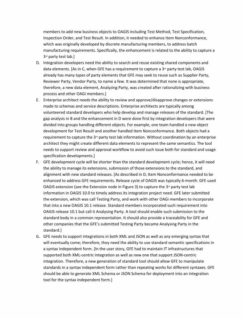
members to add new business objects to OAGIS including Test Method, Test Specification, Inspection Order, and Test Result. In addition, it needed to enhance Item Nonconformance, which was originally developed by discrete manufacturing members, to address batch manufacturing requirements. Specifically, the enhancement is related to the ability to capture a 3rd party test lab.]
D. Integration developers need the ability to search and reuse existing shared components and data elements. [As in C, when GFE has a requirement to capture a 3rd party test lab, OAGIS already has many types of party elements that GFE may seek to reuse such as Supplier Party, Reviewer Party, Vendor Party, to name a few. It was determined that none is appropriate, therefore, a new data element, Analyzing Party, was created after rationalizing with business process and other OAGi members.]
E. Enterprise architect needs the ability to review and approve/disapprove changes or extensions made to schemas and service descriptions. Enterprise architects are typically among volunteered standard developers who help develop and manage releases of the standard. [The gap analysis in B and the enhancement in D were done first by integration developers that were divided into groups handling different objects. For example, one team handled a new object development for Test Result and another handled Item Nonconformance. Both objects had a requirement to capture the 3rd party test lab information. Without coordination by an enterprise architect they might create different data elements to represent the same semantics. The tool needs to support review and approval workflow to avoid such issue both for standard and usage specification developments.]
F. GFE development cycle will be shorter than the standard development cycle; hence, it will need the ability to manage its extensions, submission of those extensions to the standard, and alignment with new standard releases. [As described in D, Item Nonconformance needed to be enhanced to address GFE requirements. Release cycle of OAGIS was typically 6-month. GFE used OAGIS extension (see the Extension node in Figure 3) to capture the 3rd party test lab information in OAGIS 10.0 to timely address its integration project need. GFE later submitted the extension, which was call Testing Party, and work with other OAGi members to incorporate that into a new OAGIS 10.1 release. Standard members incorporated such requirement into OAGIS release 10.1 but call it Analysing Party. A tool should enable such submission to the standard body in a common representation. It should also provide a traceability for GFE and other companies that the GFE’s submitted Testing Party became Analysing Party in the standard.]
G. GFE needs to support integrations in both XML and JSON as well as any emerging syntax that will eventually come; therefore, they need the ability to use standard semantic specifications in a syntax independent form. [In the user story, GFE had to maintain IT infrastructures that supported both XML-centric integration as well as new one that support JSON-centric integration. Therefore, a new generation of standard tool should allow GFE to manipulate standards in a syntax independent form rather than repeating works for different syntaxes. GFE should be able to generate XML Schema or JSON Schema for deployment into an integration tool for the syntax independent form.]

H. Since the digitalization project will use a service-oriented architecture and support multiple integration platforms, GFE needs the ability to generate service descriptions, e.g., for SOAP and REST styles web services. [Similar to G, XML-centric IT infrastructures are based on the SOAP web services standard, while JSON-centric infrastructures are based on REST style web services. A standard tool should help GFE in dealing with such technology transition by abstracting the service information from technology specifics such that most parts of the service description can be automatically generated.]
I. GFE needs the ability to model variations of lab testing business processes. [In the user story, Inspection Order may be sent to internal or external test labs to request testing of sampled products or ingredients. Therefore, there is a variation both at the business process and message levels. At the business process level, there is a need for an additional step to set up the testing service contract (dealing with price and payment) for the external test lab. At the message level, the Inspection Order needs to be able to carry the reference to the service contract for the external test lab but to the business unit and cost center for the internal lab.]
J. Enterprise architects need the ability to associate the OAGIS messages to specific business process models, and general business context, and help understand how data maps to the processes. [This requirement refers to the need to capture the relationship between the business and message level as described in I.]
K. GFE needs the ability to create usage specifications for same business objects that are used in different situations (e.g., internal vs. external test lab). [An example of variation in the canonical Inspection Order business object as pointed out in I would result in two usage specifications for the Inspection Order. The external test lab usage specification would permit the contract reference data element and disallow the business unit and cost center reference data elements/ The usage specification for the internal test lab case would have the opposite constraints. Figure 3 also partially illustrates the canonical model of Customer Party. GFE created a usage specification that includes only the data elements checked.]
L. As GFE digitalization effort grows, it will have growing number of usage specifications, service descriptions, and business processes, whose business activities overlap and can reuse existing services. GFE needs a framework and tool to apply context meta-data, search, and discover existing usage and service specifications for reuses (in short GFE needs an integration asset life-cycle management tool). [The last paragraph of the user story described that GFE planned to expand integrations to IoT device and enabling AI. The same messages used for business process improvements would also be used for enabling AI. For example, a Production Order message can be used in a workflow not only to send order from ERP to MES but also for scheduling. A scheduling team would want to know that such information service already exists so that there is no duplicate effort to create another Production Order service. An example of context meta-data includes the business units that had deployed and business processes that used such information service.]
This section has outlined a user story, from which functional requirements are derived. In the next section, detailed MSSRT functions that address these requirements are described.

5.2 MSSRT functionsThe MSSRT functions can be grouped into two categories, standard development functionality and standard usage functionality, illustrated as the mechanisms supporting the two activities in Figure 4 using the IDEF0 ICOM Activity Diagram8 [67]. The standard development functionality allows for managing the life cycle of the baseline standard (i.e., a canonical model, which is a common data structure and associated semantics such as OAGIS independent of any usage context). This functionality provides the canonical model to the standard usage functionality. The standard usage functionality provides for the life cycle management of the standard usage models (i.e., a profile, which is a subset of and restrictions on the canonical model for a particular usage context), which are based on the canonical model. Conversely, usage models are fed into the standard development functionality to be used for developing a new release of the canonical model. All functions operate on a syntax-independent representation, except those that operate on the canonical model and the usage model for a platform- and syntax-specific deployment of the models.
Figure 4: Activity model showing the model-based standard life cycle management activities and supporting functionalities
Underneath the two functionalities are the repositories of the canonical model and usage models in a syntax independent form. It is important to note that logically (i.e., in a particular release) there is a single canonical model, from which a number of usage models are derived. A usage model, also called a profiled model, is a subset of the canonical model, with context information and, optionally, with semantic restrictions (such as additional documentation, code lists and data type restrictions, and data element dependency rules), and extensions. These concepts, except the extensions, make up the core design of the MSSRT and they are based on the UN/CEFACT Core Component Specification (CCS) [68]. Details about the MSSRT core design will be discussed in section 6.
8 IDEF0 models an activity as a box with ICOM, where ‘I’ refer to an Input (an arrow from the left), ‘C’ refers to a Control (arrow from the top, providing specifications or constraints), ‘O’ refers to an Output (arrow coming out on the right), and ‘M’ refers to a mechanism representing a tool or method (arrow from the bottom).

Extension has been an essential, practical concept in OAGIS since its inception. Although the (syntax specific) design around extension has evolved over major releases of the standard, its main purpose remains unchanged; that is, it allows for an enterprise deploying OAGIS to add data elements to the canonical model either because they are proprietary or represent additional requirements not satisfied by the current version of the standard. The MSSRT adds an additional purpose to the extension as a mechanism for standard users to submit an enhancement request to the standard. The MSSRT records the submissions, which provide traceable information about changes made to the standard. In the following subsections, details of the two core sets of MSSRT functions are described. Mapping to supported functional requirements outlined in the previous subsection is also provided.
5.2.1 Standard development functionalityThe standard development functionality can be further classified into a syntax independent and a syntax specific standard management functionality as shown in Figure 5.
5.2.1.1 Syntax independent standards management functionality.
The following highlights core functions in the syntax independent functionality.
5.2.1.1.1 Create, Update, Revise, Delete, Discard (or Purge) and Deprecate parts of the canonical model9 (Req. C)
In addition to Create and Update that have intuitive meanings, Revise is the ability of the system to retain history of changes to parts of the model. Traditionally, data exchange standards are only versioned at the release or file level. The MSSRT tracks revisions down to the individual data structure level. Delete is different from Discard. In the former case, the system still keeps the record of the deleted entity as part of the revision; while the latter case means a permanent removal. Both Delete and Discard are allowed only in certain situations. Several conditions must be considered when discarding a component, particularly to ensure the integrity of existing relationships. Deprecate is an important feature that allows for correction to the canonical model while still maintaining the backward compatibility. An advanced function should be available to formally track the relationship between the deprecated entity and the replacement entity.
5.2.1.1.2 Review (Req. C)To allow for proper governance, parts of the canonical model that are being created or revised shall go through a review process. In the MSSRT, states such as Editing, Candidate, and Published are available for governance purposes. In the Editing state the system locks the entity to permit changes to the entity only by the owner. The owner subjects the entity for review and comments in the Candidate state. An advance function has been planned to keep, during this state, records of comments – an important semantic information usually lost in a standard development that has no proper tool support10. The Published state signifies a stable revision where comments have been resolved and that it is proper to reference or use the entity. A published revision generally cannot be purged from the system.
9 Generally, a canonical model can be viewed as encompassing data structure, data type, and code list definitions.10 In practice, some data elements are similar in semantics because formal documentations are oftentimes not sufficiently rich. Records of conversations and comments can shed more light.

5.2.1.1.3 Release management (Req. C)A release is a snapshot of a library of published components in the canonical model, i.e., it is a revision of the standard. A release is typically scheduled around a portion of standard enhancement and bug fix requests. The release management provides the life cycle management function to the release process. The release process includes a draft state and a final state. Several drafts may be necessary before a release is finalized, at which point, prior drafts can be discarded. The release management also provides the only opportunity for unused, published revisions of components in the (current working) release to be purged from the system when the release is finalized.
5.2.1.1.4 Search (Req. A, D)Search is an essential function to enhance reuse of parts of a standard and reduce duplicates. Both standard developers and users need the search function. It should take into account several fields in the model such as name and description and allow for filtering of different entity types, states, owners, releases, etc. The MSSRT has implemented an initial semantic search using the Levenshtein semantic distance metrics. In addition, other semantic search capabilities have been planned such as lexical search based on a lexical library (e.g., WordNet) or a domain specific thesaurus.
5.2.1.1.5 Import (Req. B)Import is a function to assist in harmonization between an existing proprietary or external standard and the canonical model. This occurs in OAGi when an enterprise application vendor or a manufacturing enterprise donates its proprietary canonical library. A search capability shall be applied to the imported content to help standard developers with the harmonization.
5.2.1.1.6 Analysis (Req. A, B, E)Analysis is the ability to display differences between revisions of various parts of the model at various levels of granularity. Finding out differences between two revisions of the data structure based on the traditional syntax-specific representation of the standard is cumbersome. For example, if there is an inheritance hierarchy in a particular semantic element in the model, standard developers or users have to manually open each element in the hierarchy to find out the actual differences of the element at the bottom of the hierarchy. An even more difficult situation occurs when a particular semantic element has a deep tree structure produced by several referenced definitions. The analysis function in the model-based tool should eliminate all these difficulties and is able to present differences between revisions of semantic elements virtually with a single click.
5.2.1.1.7 Extension rationalization (Req. E, F)As shown in Figure 5, the syntax independent usage model is fed back to the Develop Canonical Model activity. This function allows standard developers to take those usage models submitted by various users, analyze the extensions made in those models based on their contexts and semantics, and harmonize them into changes or enhancements to the canonical model. The process can result in a new release of the standard. This function should as much as possible retain the traceability between the submitted extensions and changes to the canonical model. This traceability information, part of the canonical model change information, is used later in the syntax independent usage model upgrade described in the Standard usage functions section.

Figure 5: Activity diagram showing functionalities and information relevant to the standard development functionality
5.2.1.2 Syntax specific standards management functionality
5.2.1.2.1 Namespace management (Req. C, G)For example, in case of XML schema syntax, this function allows for creation and maintenance of namespaces.
5.2.1.2.2 Schema module management (Req. C, G)When the canonical model is expressed in a certain syntax and style (see expression generation below), schema modules indicate the physical file and directory where parts of the model should be serialized to. The schema module management allows creation and maintenance of file paths and their dependencies. It also includes the function to assign component parts of the canonical model to a module.
5.2.1.2.3 Expression generation (Req. C, G)The canonical model expression generation is a function to generate the canonical model in a particular syntax and style. Examples of syntaxes are XML schema or JSON schema. In a particular syntax, there may be different styles. In XML schema, for example, Russian Doll and Garden of Eden [69] are the popular styles that are fit for different purposes. The Russian Doll style provides more precise definitions and, hence, is better for representing a service or interface definition. It is, however, limited to a single namespace, resulting in a bigger schema than the Garden of Eden schema that provides the same structural definition. The Garden of Eden schema are less precise because it is catered for a maximum reuse. It is however more suitable for code generation to process the instance data. The expression generation function enables generation of these variations for various purposes. Two other XML schema styles are Venetian Blind and Salami Slice [69]. While variations of these two styles are also used by industry, the canonical model is typically generated in the Garden of Eden style. The Russian Doll style is typically used for the usage model discussed in Standard usage functions section.
5.2.1.2.4 Primitive type management (Req. C, G)Different syntaxes support different type systems. This function allows the user to create the mapping between types in different syntaxes, supporting the expression generation.

The syntax-specific standard management functionality may grow as more syntaxes and different integration styles are supported due to their differing purposes and features.
5.2.2 Standard usage functionsFigure 6 below is a decomposition of the Develop Usage Model activity in Figure 4. Specifically, it shows that the standard usage functionality has been decomposed into Business Process Management Functionality, Context Management Functionality, Syntax Independent Usage Model Management Functionality, and Syntax Specific Expression Generation Functionality. Subsequently, core functions in these functionalities are described.
Figure 6: Activity diagram showing functionalities and information relevant to the standard usage functionality
5.2.2.1 Business process management and context management functionalities (Req. I, J, K, L)
Indeed, business processes are part of the integration requirements (an input to several activities). In early development of the standard canonical model, business processes provide crucial inputs to identify common data exchange transactions and objects. When the standard becomes mature and reuse becomes common for the standard, business processes involved in an integration project drive the usage model development that can lead to reuses and enhancements of the standard canonical model. Consequently, business processes provide well-defined contexts for standard usages. In other words, keeping track of the relationship between business processes and standard usages will help in reusing the standard and associated services. This leads to increase in productivity. Using business processes to drive the standard development and documentation is not a new idea. The idea started in the Open EDI initiative [70], continued in the ebXML activities [26], and other prior research [71-73].
The business processes themselves can also be reused or adapted that lead to data exchange standard and service reuses. Hence, the requirement for business process management functionality includes not only business processes authoring functionality available in typical business process management or enterprise architect tools, but also additional functionalities to 1) manage business process meta-data, (e.g., using the 5WH questions with respect to the Zachman Enterprise Architecture Framework [75]), and 2) assign standard usage models to integration interactions. Both of the functionalities assist in the

search and reuse of business processes that in turn lead to greater reuse of services and standard usage models. Further detail about these business process management functionalities can be found in other papers focusing on the business process cataloging and classification system (BPCCS) [72-73].
As described earlier, with support from the BPCCS, a business process, or more specifically an interaction within a business process, can be used to specify a well-defined context for a standard usage. In absence of the BPCCS, usage context may be specified with a combination of classification scheme values. Such business context model is specified in the CCS standard [68]. Each classification used within a context represents a context dimension (i.e., context category) such as industry, role, integration type (e.g., application-to-application, business-to-business), application type, or even production type [68]. The context management functionality provides a function to associate entities from the business or other classification scheme values to a standard usage model and a function to manage context dimensions, classification schemes, and classification values themselves.
5.2.2.2 Syntax-independent usage model management functionality
Core functions of the syntax independent usage model management are described in the following sub-sections.
5.2.2.2.1 Create, Update, Copy, Discard (or Purge), Extend, and Upgrade a usage model (Req. K)A usage model is based on a part of the canonical model. In the Create process, a data structure from the canonical model is chosen as a base (i.e., base data structure) of the usage model and also a usage context is assigned. As a result, the usage model maintains a reference to the canonical model.
In the Update process, the user should be able to specify semantic restrictions on the base data structure. Semantic restrictions can include enable/disable data elements, restrict primitive data types, assign a fixed value or code list, enable/disable nullability, specify cross-data-element rules, and provide context specific documentations. The other advanced semantic restriction feature is the data element specialization. This can be viewed as company specific inline specialization where a data element is further qualified with an open-ended type field. For example, the canonical model may provide a Supplier Party element whose one of the data field is type code. A company or industry may have its own specific kinds of suppliers such as supplier with different level of preferences. In many cases, standard users would like to explicate these differences into different data elements making it easier to further restrict the semantics, document mappings, and more.
The Copy function allows the user to efficiently create another usage model for another context or create a revision of it when there is an integration requirement change in the same context.
The Discard function allows the user to purge the usage model that is in a particular state during its review process (described in the next functionality).
The Extend function allows the user to add data elements that do not exist in the base canonical model into the usage model. An extension may reuse an existing semantic data structure already defined in the canonical model of the standard or in a user-defined canonical data structure. User-defined canonical

data structures are shared components created by the standard users. They can be submitted to the standard body for rationalization into the standard.
Upgrade is the process to migrate existing usage models based on a prior release of the canonical model to a new release. It is another efficient function made possible by the model-based standard development and usage. Because the usage model maintains a reference to its base canonical model and the underlying system maintains the ‘delta’ between revisions of the canonical model, the system automatically upgrades most parts of the usage model except the extensions. However, with traceability information captured in the extension rationalization function, the system can assist the user in migrating the extension during the upgrade.
5.2.2.2.2 Review (Req. E)Similar to the function in the syntax independent canonical model management, this function supports usage model governance. It allows the usage model to go through a review and approval process. In the MSSRT, states such as Editing, Candidate, and Published are available. In the Editing state the system locks the usage model so that it can be viewed and changed only by the owner. The usage model can also be discarded in that state. The author subjects the usage model for review and comments in the Candidate state. Comments made during the review process are recorded for subsequent use. When cycles of reviews and changes are needed, the author can traverse the Editing and Candidate states. The Published state signifies a production-ready version of the usage model and cannot be further changed or discarded from the system.
5.2.2.2.3 Search (Req. L)In addition to the search criteria mentioned in the canonical model search, a usage model should be searchable within its context. Specifically, lexical and literal search should be provided across name, documentation, and semantic restriction fields. Such in-context search of the canonical model (to find a data element that is part of the base canonical model but not yet part of the usage model) is a feature that will enhance the speed of the usage model development. This feature is especially important because a particular canonical message may contain hundreds of thousands of data elements.
5.2.2.2.4 Analysis (Req. E, K)Analysis is a function that allows visual comparison between usage models. It will help find commonalities between different versions of the usage models or between usage models in differing contexts. This, in turn, may lead to more effective life-cycle management of the usage models through their merging, generalization, or introducing other useful relationships.
5.2.2.3 Syntax-specific expression generation functionality
Expressions of a usage model may be generated (or serialized) only as schemas or service descriptions (known as API specification) which in turn contain schemas. Further details about these two options are as follows.
5.2.2.3.1 Schema generation (Req. G)As described in the canonical model expression generation, the usage model may be expressed in various schema syntaxes and styles. However, the Russian Doll style provides the most precise definition

for implementation documentation and instance validation. In addition, the schema may be generated with different levels of meta-data and documentation. Finally, schema package is another notion that should be supported where multiple usage models are generated into a single schema. It is commonly used for putting together a set of related usage models for a business process or for a service description that typically contain multiple interface/operation definitions (e.g., create, update, query, validate) for a business object (e.g., bill of materials).
5.2.2.3.2 API specification or service description generation (Req. H)These are generally specifications that describe how a software client should interact with an application. Each of them may be integration pattern- and protocol-specific, such as large aggregate transactions between enterprise applications vs. smaller, chattier transactions for mobile applications and protocols such as Web Services vs. REST, respectively. With some additional information provided by the user, the model-based standard development and usage system can generate such a specification (such as WSDL [24] or Open API [30]) that includes the usage model. The generated specification can be directly deployed to a middleware tool, saving significant development time.
6 The MSSRT Core DesignCore design of the MSSRT is based on the UN/CEFACT Core Component Specification (CCS), which is an international standard for modeling data exchange specification in a syntax-independent representation [68]. CCS can be viewed as a meta-model for model-based standards development and usage. Its main concepts include Business Context (BC), Core Component (CC), and Business Information Entity (BIE). The MSSRT adopts these main concepts as follows: CCs are the standard canonical model, while BIEs are usage models created as restrictions on CCs in a particular BC. A BC indicates applicable usage situation of the BIE. It is a combination of context values from various context schemes. A context scheme, also known as a classification scheme, can be a flat list of values, a taxonomy of values, or a reference to a message exchange flow in a business process model. A context scheme can be, for example, an industry or geopolitical classification. While CCS suggested eight context categories for the context scheme, others may be used as illustrated in the example below.
We explain the three main CCS concepts by way of a practical example next and point the interested reader to the formal CCS meta-model for details of the concepts [68].
Bill of Materials (or commonly known as BOM) is an information object for capturing relationships between items (component parts) that are assembled into another item. Properties of a BOM, such as the item quantity or even assembly instructions, can also be captured as part of BOM. As enterprise applications evolve with more functions and innovations, the basic information of BOM applies to many product life-cycle stages and number of data elements in BOM continues to grow. The top of Figure 7 illustrates the relationship between the three CCS main concepts: BOM is an example of the canonical Core Components on the left-hand-side (LHS), while several context-specific notions of BOM are indicated on the right-hand-side (RHS) after specifying the Business Context along with the Core Component on the LHS. Essential data elements differentiating usages of the BOM core component are also illustrated under each BIE.
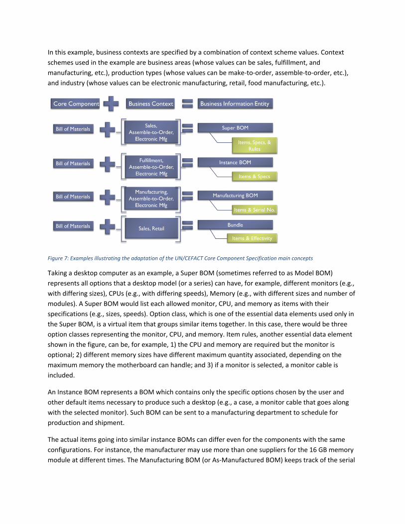
In this example, business contexts are specified by a combination of context scheme values. Context schemes used in the example are business areas (whose values can be sales, fulfillment, and manufacturing, etc.), production types (whose values can be make-to-order, assemble-to-order, etc.), and industry (whose values can be electronic manufacturing, retail, food manufacturing, etc.).
Figure 7: Examples illustrating the adaptation of the UN/CEFACT Core Component Specification main concepts
Taking a desktop computer as an example, a Super BOM (sometimes referred to as Model BOM) represents all options that a desktop model (or a series) can have, for example, different monitors (e.g., with differing sizes), CPUs (e.g., with differing speeds), Memory (e.g., with different sizes and number of modules). A Super BOM would list each allowed monitor, CPU, and memory as items with their specifications (e.g., sizes, speeds). Option class, which is one of the essential data elements used only in the Super BOM, is a virtual item that groups similar items together. In this case, there would be three option classes representing the monitor, CPU, and memory. Item rules, another essential data element shown in the figure, can be, for example, 1) the CPU and memory are required but the monitor is optional; 2) different memory sizes have different maximum quantity associated, depending on the maximum memory the motherboard can handle; and 3) if a monitor is selected, a monitor cable is included.
An Instance BOM represents a BOM which contains only the specific options chosen by the user and other default items necessary to produce such a desktop (e.g., a case, a monitor cable that goes along with the selected monitor). Such BOM can be sent to a manufacturing department to schedule for production and shipment.
The actual items going into similar instance BOMs can differ even for the components with the same configurations. For instance, the manufacturer may use more than one suppliers for the 16 GB memory module at different times. The Manufacturing BOM (or As-Manufactured BOM) keeps track of the serial

numbers of items going into the product shipped to the customer. It provides for the warranty, recall, and maintenance tracking.
The last example in the figure shows that BOM may be used in a different industry, like retail, to capture product-bundling. It is a simple product structure retailer uses for combining related items together and to possibly offer a discount, say, over a weekend sales event, which is why the effective time period is shown as an essential data element in the Bundle. Indeed, bundles are also commonly used to represent telecommunication services (phone, TV, and internet).
With this example, one question may arise: Why the standard didn’t define the four BIE concepts as separate objects in the canonical model? The reasons are of pragmatic nature. First, even if the four concepts are defined separately in the canonical model, there will still be variations of them in various contexts. The other reason is related to the integration implementation. The availability of the aggregate BOM object provides for a common abstract service for invoking and routing all BOM related transactions. Integration developers also have some economies of scale benefits in terms of development and maintenance (e.g., code reuse) to motivate consolidation of multiple transaction types into a single service. In fact, a monolithic ERP application may handle Super BOM, Manufacturing BOM, and Instance BOM with a same aggregate object and interface. If these were three separate interfaces, developers would have to maintain three separate, yet overlapping code lines. This is indeed one area where the ontology-based semantic data standards can complement the traditional standards. That is, it can be used to recognize data on the wire or in the database to identify what it is about, e.g., either Super BOM, Instance BOM, or Manufacturing BOM.
An early prototype of the MSSRT that followed the above overall design, used OAGIS content in the canonical model, and that met a significant portion of the discussed requirements, has been developed and demonstrated. The prototype was subsequently piloted by aerospace, food, agricultural manufacturing, and even human capital management services companies. On-premise adoptions of the tool have started by these individual companies weaving the tool into their training and daily operation. Results have shown a significant improvement as one early adopter stated “The tool have helped to rapidly create profiled APIs and JSON schema by efficiently searching and selecting only the elements needed from the cross-industry standard. What used to take days, or weeks in some cases, now is completed typically within an hour.” Nevertheless, the ultimate goal of the tool is to be a hosted service to facilitate easier standard feedback and significantly more efficient development and maintenance of the standards. To that end, additional functionalities were requested from industry along with the performance enhancement for the adoptions to be successful at that scale. This work has been started and will be discussed in the future publications.
7 Summary and OutlookThis paper provides a history and a trend analysis of manufacturing software and systems integration from the semantic interoperability perspective. It also discusses the functional requirements of a software system that was necessary to support the emerging trend.

The history was discussed in three evolutionary periods, namely Stone Age, Bronze Age, and Iron Age. The Stone Age was characterized by inflexible integrations that are difficult and costly to implement and change. The Bronze Age improved over the Stone Age by the availability of less expensive internet-based data transmission technologies and an explosion of computer-interpretable data exchange standards that were mostly delivered in syntax-specific specifications. Free, open source software tools were also available to interpret these standards and to process the corresponding data in a scalable way that was not specific to a particular message. However, there had been a proliferation of data representation syntaxes; therefore, several data exchange standards were trending toward model-based, syntax independent delivery of the specifications in the Iron Age.
A software tool is necessary to support this trend, e.g., to generate a syntax-specific, deployable version of the data exchange standard and to support increasingly mixed integration environments necessary for co-existence of old and new technologies. In addition, better documentation at the level of business processes is needed in order to quickly find and reuse existing data exchange standards, their derivatives, and corresponding implementations [76]. To that end, functional requirements of such a system was provided. The system has been developed and adopted by individual enterprises and the results are promising. Its core design, which was based on an international standard, was briefly described. Further details about the design is a topic of a future paper. In particular, although the standard provides core concepts, it does not provide design related to standard revision management, release management, and syntax specific and integration pattern mapping. Several computational innovations will be required to develop a system supporting such a model-based standard development and usage. An application design that is user-friendly and has a scalable performance when dealing with a large standard message object that amount to three-hundred thousands data elements is an example of a feat. In addition, there is still further research and experiment needed to obtain a best practice regarding the use of business context as a meta-data to enhance reuse of integration artifact.
Lastly, the outlook that is coming upon us is the ontology-based semantic data standards. Evidences of successes have been shown in biomedical and financial industries. The Industrial Ontologies Foundry (IOF) has been formed for the industrial manufacturing industry. Early industrial experiences have indicated specific niche for the ontological model such as for business intelligence, knowledge and information discovery rather than for exchanging traditional business transactions. However, computing resources are becoming more powerful and cost less. It remains to be seen whether the benefits will outweigh the cost and speed for ubiquitous use of ontology-based semantic data standards.
Acknowledgement
The authors wish to thank all past and present members of the OAGi Semantic Refinement Working Group who have collectively contributed to the MSSRT work including Dr. Yunsu Lee – NIST (now at Samsung), Jaehun Lee – NIST (now at Samsung), Taehun Lee – NIST (now at POSTECH), Miroslav Ljubicic – NIST (now at Glovo), Michael Rowell – Oracle, Jeff Rice – Boeing, Steffen Fohn – ADP, Jim Wilson – OAGi, and David Connelly – OAGi (now retired). This work was partially funded by National Institute of Standards and Technology (NIST) Award 70NANB17H261 with University of Maryland Baltimore County.

DISCLAIMER
Certain commercial software products are identified in this paper. These products were used only for demonstration purposes. Their use does not imply approval or endorsement by NIST, nor does it imply these products are necessarily the best available for the purpose.
REFERENCES
1. Moghaddam, M., Cadavid, M. N., Kenley, C. R., & Deshmukh, A. V. (2018). Reference architectures for smart manufacturing: A critical review. Journal of manufacturing systems, 49, 215-225.
2. Wu, D., Greer, M. J., Rosen, D. W., & Schaefer, D. (2013). Cloud manufacturing: Strategic vision and state-of-the-art. Journal of Manufacturing Systems, 32(4), 564-579.
3. Lu, Y., Morris, K. C., & Frechette, S. (2015, August). Standards landscape and directions for smart manufacturing systems. In 2015 IEEE International Conference on Automation Science and Engineering (CASE) (pp. 998-1005). IEEE.
4. Ivezic, N., & Srinivasan, V. (2016). On architecting and composing engineering information services to enable smart manufacturing. Journal of computing and information science in engineering, 16(3), 031002.
5. IETF RFC 1831 (1995). RPC: Remote Procedure Call Protocol Specification Version 2.6. Object Management Group (OMG) (1991). The Common Object Request Broker: Architecture and
Specification version 1.0.7. Smith, B., Rinaudot, G.R., Reed, K.A., and Wright, T. (1988). Initial Graphics Exchange Specification
(IGES) Version 4.0. NBSIR 88-3813.8. ISO 10303-1:1994 Industrial automation systems and integration -- Product data representation and
exchange -- Part 1: Overview and fundamental principles.9. ASC X12 EDI standard web page. http://www.x12.org/x12-work-products/x12-edi-standards.cfm.
Accessed August 8, 2018.10. ISO 10303-11:2004 Industrial automation systems and integration -- Product data representation
and exchange -- Part 11: Description methods: The EXPRESS language reference manual.11. W3C (1997). Extensible Markup Language version December 8, 1997 (first stable version).12. W3C XML Schema specification web site. https://www.w3.org/XML/Schema. Accessed August 8,
2018.13. ISO/IEC JTC1/SC34 (1998). Document Description and Processing Languages.14. Open Applications Group (2017). Open Application Groups Integration Specification Release 10.4.15. OASIS Universal Business Language Technical Committee (2018). Universal Business Language
version 2.2.16. FIATECH (2004). Automating Equipment Information Exchange (AEX) Public Release version 1.0. 17. ISO 15926-7:2011. Industrial automation systems and integration -- Integration of life-cycle data for
process plants including oil and gas production facilities -- Part 7: Implementation methods for the integration of distributed systems: Template methodology.
18. MTConnect Institute, 2014, MTConnect standard version 1.3.0.19. OPC Foundataion. OPC Unified Architecture Specification V. 1.0.

20. IETF RFC 3335 (2002). MIME-based Secure Peer-to-Peer Business Data Interchange over the Internet.
21. OASIS (2007). OASIS ebXML Messaging Services Version 3.0.22. Object Management Group (OMG) (1997). The Common Object Request Broker: Architecture and
Specification version 2.0.23. W3C (2000). Simple Object Access Protocol (SOAP) Version 1.1.24. W3C (2006). Web Services Description Language (WSDL) Version 2.0: Part 1 Core Language.25. OASIS (2007). Web Services Business Process Execution Language Version 2.0.26. UN/CEFACT Technique and Methodology Group (TMG) (2003). UN/CEFACT Modeling Methodology
User Guide Revision 12 and related specifications. Available online at https://www.unece.org/cefact/umm/umm_index.html.
27. Object Management Group (2017). Unified Modeling Language (UML) version 2.5.1. Available online at https://www.omg.org/spec/UML/About-UML/.
28. Damodaran, S. (2004, May). B2B integration over the Internet with XML: RosettaNet successes and challenges. In Proceedings of the 13th international World Wide Web conference on Alternate track papers & posters (pp. 188-195). ACM.
29. ECMA International (2017). ECMA-404 The JSON Data Interchange Syntax 2nd Edition.30. Open API Specification version 1.0, Released August 10, 2011.31. OASIS (2018). Open Data Protocol (ODATA) Version 4.01. Part 1: Protocol. Note that according to
Wikipedia (https://en.wikipedia.org/wiki/Open_Data_Protocol. Accessed August, 18, 2018), the first 3 versions of ODATA were released by Microsoft since 2007. These earlier versions are available at https://www.odata.org/documentation/; however, the released dates were not specified.
32. IETF (2018). JSON Schema Core, Draft-handrews-json-schema-01, valid March 19, 2018 to September 20, 2018.
33. Klyne , G. and Carroll, J. (2004). Resource Description Framework (RDF): Concepts and Abstract Syntax, W3C Recommendation 10 February 2004.
34. Hitzler, P., Krötzsch, M., Parsia, B., Patel-Schneider, P. and Rudolph, S. (2009). OWL 2 Web Ontology Language Primer, W3C Recommendation 27 October, 2009.
35. W3C (2012). OWL 2 Web Ontology Language Document Overview (Second Edition), W3C Recommendation 11 December 2012.
36. Clark, J. and DeRose, S. (1999). XML Path Language (XPath) Version 1.0, W3C Recommendation 16 November 1999 (Status updated October 2016).
37. Robie, J., Dyck, M. and, Spiegel, J. (2017). XQuery 3.1: An XML Query Language, W3C Recommendation 21 March 2017.
38. Robie, J., Dyck, M. and, Spiegel, J. (2017). XML Path Language (XPath) 3.1, W3C Recommendation 21 March 2017.
39. OMG (2017). System Modeling Language (SysML), Version 1.5.40. Kleppe, A. G., Warmer, J., Warmer, J. B., & Bast, W. (2003). MDA explained: the model driven
architecture: practice and promise. Addison-Wesley Professional.41. Open Applications Group (OAG), Semantic Refinement Working Group.
https://oagi.org/OurCommunity/WorkingGroups/tabid/149/Default.aspx. Accessed August 18, 2018.

42. Mikos, W. L., Ferreira, J. C., Botura, P. E., & Freitas, L. S. (2011). A system for distributed sharing and reuse of design and manufacturing knowledge in the PFMEA domain using a description logics-based ontology. Journal of Manufacturing Systems, 30(3), 133-143.
43. Lu, Y., Xu, X., & Xu, J. (2014). Development of a hybrid manufacturing cloud. Journal of Manufacturing Systems, 33(4), 551-566.
44. Camarillo, A., Rios, J., & Althoff, K. D. (2018). Knowledge-based multi-agent system for manufacturing problem solving process in production plants. Journal of manufacturing systems, 47, 115-127.
45. Open Biological and Biomedical Ontology Foundry Web Site – http://obofoundry.org. Accessed July 11, 2018.
46. Hoehndorf, R., Oellrich, A., & Rebholz-Schuhmann, D. (2010). Interoperability between phenotype and anatomy ontologies. Bioinformatics, 26(24), 3112-3118.
47. Brinkman, R. R., Courtot, M., Derom, D., Fostel, J. M., He, Y., Lord, P., & Ruttenberg, A. (2010, June). Modeling biomedical experimental processes with OBI. In Journal of biomedical semantics (Vol. 1, No. 1, p. S7). BioMed Central.
48. Özgür, A., Xiang, Z., Radev, D. R., & He, Y. (2011, December). Mining of vaccine-associated IFN-γ gene interaction networks using the Vaccine Ontology. In Journal of biomedical semantics (Vol. 2, No. 2, p. S8). BioMed Central.
49. FIBO spec page - https://www.edmcouncil.org/financialbusiness, last access 2018/07/11.50. Kulvatunyou, B., Ivezic, N., & Lee, Y. (2014). On enhancing communication of the manufacturing
service capability information using reference ontology. International Journal of Computer Integrated Manufacturing, 27(12), 1105-1135.
51. Klüwer, J. (2017). Using ontologies to check that requirements are met. 2017 Subsea Valley Master Class: Digital Engineering. Available online at http://sirius-labs.no/wp-content/uploads/2017/04/SubseaValley2017.pdf
52. Gyawali, B., Shimorina, A., Gardent, C., Cruz-Lara, S., & Mahfoudh, M. (2017, May). Mapping natural language to description logic. In European Semantic Web Conference (pp. 273-288). Springer, Cham.
53. Harcuba, O., & Vrba, P. (2015, September). Ontologies for flexible production systems. In Emerging Technologies & Factory Automation (ETFA), 2015 IEEE 20th Conference on (pp. 1-8). IEEE.
54. Dahl, M. A., Levinskas, E. J., Walsh, P. L., Gianni, R. G., Tanner, J. G.,& Vergaray, R. A. (2015). U.S. Patent No. 8,954,474. Managing data systems to support semantic-independent schemas. Washington, DC: U.S. Patent and Trademark Office.
55. KIMBERLY, Greg A. et WALIA, Harshpreet S. Mediation computing device and associated method for generating semantic tags. U.S. Patent No 9,336,187, 10 mai 2016.
56. S iu, K., Moitra, A., Durling, M., Crapo, A., Li, M., Yu, H., ... & Russell, D. (2017, September). Flight critical software and systems development using ASSERT™. In Digital Avionics Systems Conference (DASC), 2017 IEEE/AIAA 36th (pp. 1-10). IEEE.
57. Zhao, L., Ichise, R., Mita, S., & Sasaki, Y. (2015). Core Ontologies for Safe Autonomous Driving. In International Semantic Web Conference (Posters & Demos).
58. Rychtyckyj, N., Raman, V., Sankaranarayanan, B., Kumar, P. S., & Khemani, D. (2016, February). Ontology Re-Engineering: A Case Study from the Automotive Industry. In AAAI (pp. 3974-3981).

59. Greenly W., Sandeman-Craik C., Otero Y. & Streit J. “Case Study: Contextual Search for Volkswagen and the Automotive Industry.” Tribal DDB UK, 2011.
60. Kulvatunyou, B. and Morris, K.: Working Towards an Industrial Ontology Foundry to Facilitate Interoperability. http://blog.mesa.org/2017/03/working-towards-industrial-ontology.html. Accessed 2018/07/11.
61. Kulvatunyou, B., Wallace, E., Kiritsis, D., Smith, B., and Will, C. (2018). Industrial Ontologies Foundry Proof-of-Concept Project. Advances in Production Management Systems, International Conference, Seoul, South Korea.
62. Franz Inc. AllegroGraph graph database. https://franz.com/agraph/allegrograph/. Accessed August 8, 2018.
63. Stardog Union. Stardog, the Knowledge Graph Platform for the Enterprise. https://www.stardog.com/. Accessed August 8, 2018.
64. Neo4j Inc. Neo4j graph database platform. https://neo4j.com/. Accessed August 8, 2018.65. Soylu, A., Giese, M., Jimenez-Ruiz, E. et al. Univ Access Inf Soc (2016) 15: 129.66. Google Developers. Protocol Buffers. https://developers.google.com/protocol-buffers/. Accessed
August 4, 2018.67. Mayer, R. J. (1992). IDEF0 function modeling. A Reconstruction of the Original Air Force Wright
Aeronautical Laboratory Technical Report, AFWAL-TR-81-4023 (The IDEF0 Yellow Book), Knowledge-Based System Inc, College Station, TX.
68. ISO 15000-5: 2014. Electronic business extensible markup language (ebXML) – Part 5: Core components specification (CCS), Geneva, Switzerland.
69. Khan, A. and Sum, M. (November 2006). Introducing Design Patterns in XML Schemas. http://www.oracle.com/technetwork/java/design-patterns-142138.html. Accessed August 4, 2018.
70. Lee, R. M., & Bons, R. W. (1996). Soft-coded trade procedures for open-edi. International Journal of Electronic Commerce, 1(1), 27-49.
71. Gagne, D. and Bock, C. (2014). Feasibility of Integrating OAGIS and BPMN. OAGI White Paper.72. Ivezic, N., Ljubicic, M., Kulvatunyou, B., Leiva, C., Nieman, S., and N., Marjanovic, Z. (2016). Towards
business process catalog for cloud-enabled service-oriented architectures. Proc. of the ASME 2016 Manufacturing Science and Engineering Conference (MSEC), June 27-July 1, 2016, Blacksburg, VA.
73. Ljubicic, M., Ivezic, N., Kulvatunyou, B., Nieman, S., Anicic, N., and Marjanovic, Z. (2017). Business process model life-cycle management in cloud manufacturing. Proc. of the ASME 2017 International Manufacturing Science and Engineering Conference (MSEC), June 4-8, 2017, Los Angeles, CA.
74. Gamma, E., Helm, R., Johnson, R., and Vlissides, J. (1994). Design Patterns: Elements of Reusable Object-Oriented Software. Addison Wesley. pp. 185ff. ISBN 0-201-63361-2.
75. Zachman, J. (2002). The zachman framework for enterprise architecture. Zachman International, 79.76. Hofreiter, B., Huemer, C., & Naujok, K. D. (2004). Un/cefact’s business collaboration framework-
motivation and basic concepts. Coordination and Agent Technology in Value Networks. Gito, Berlin, 93-108.