frx-3e test v7.55 issue1.06 june2014
TRANSCRIPT

7/24/2019 Frx-3e Test v7.55 Issue1.06 June2014
http://slidepdf.com/reader/full/frx-3e-test-v755-issue106-june2014 1/214
T101-1755-05,06,001
FRX-3E (SNMP-SV: V7.55)
Practices
Equipment Specification
Equipment Manual
Installation Manual
> On-Site Test & Maintenance
Web-Based LT Manual
T101-1755-05
ON-SITE TEST &
MAINTENANCE
FRX-3E IP/SDH RADIOEcological, Econom ical, Ethernet
SNMP-SV: V7.55
Issue1.06: June 2014
FUJITSU WIRELESS SYSTEMS LIMITED

7/24/2019 Frx-3e Test v7.55 Issue1.06 June2014
http://slidepdf.com/reader/full/frx-3e-test-v755-issue106-june2014 2/214
01 Issue History
Issue No. Issue Date History
1.00
1.01
1.02
1.03
1.04
1.05
1.06
30th October, 2010
20th December, 2010
10th March, 2011
30th May, 2011
10th June, 2011
20th August, 2011
20th November, 2011
20th February, 2012
20th March, 2012
20th June, 2012
20th
July, 2012
20th August, 2012
20th September, 2012
10th November, 2012
20th December, 2012
20th February, 2013
30th June, 2013
20th February, 2014
30th June, 2014
New release of DOC issue 1.0x series
New release of FRX-3E IP/SDH RadioDraft first issue
Rewrote based on latest R&D development stageDraft second issue
Review and re-wrote
First issueRegistered & Publication
Draft Second issue1
Revision of SV Condition Item & DescriptionSecond issue
Registered & Publication
Third issue publicationNew release of SNMP-SV firmware: V7.52Chapter 2, Sec. 2 WebLT PM revised
Fourth issue1New release of SNMP-SV: V7.53
Fourth issue2
Hardware setting on GESWFifth issue1
New release of SNMP-SV: V7.54
TRMD v1/v2 & GESW v1/v2 added
Fifth issue2Description of WebLT & Card replacement revised
Fifth issue3Some errors revised
Fifth issue4Some errors revised
Fifth issue5Some errors revised
Fifth issue6Reviewed all and revised
Fifth issue7Caution/Notice/Note defined
Fifth issue8DC power supply feed revised & others
SD/XSD/XPIC DADE setting of Hop Test revisedFifth issue9
Chapter 2, Sec. 2 WebLT revised
Sixth issue1New release of SNMP-SV: V7.55

7/24/2019 Frx-3e Test v7.55 Issue1.06 June2014
http://slidepdf.com/reader/full/frx-3e-test-v755-issue106-june2014 3/214
02 Scope
This document describes all of Commissioning Test & Maintenance for Fujitsu’s FRX-3E
(SNMP-SV: V7.55) SDH Radio equipment with multiple baseband interfaces. For more
detailed technical information, please refer to another FRX-3E document.
Specifications are subjected to change without notice due to Fujitsu’s design improvements.
A person who refers this document for On-Site Test Procedure, should be familiar withFRX-3E SDH radio, a PC (Personal Computer), an operating system, an applicationsoftware usage on the PC and basic of IP (Internet Protocol) network.
03 Non-Disclosure
Fujitsu Wireless Systems Limited has taken every care that the contents of this documentare correct at the time of going to press. If any errors are found, or any other comments arewished to be made, Please do not hesitate to contact us.
The contents of this document are protected under copyright and contain commercially
and/or technically confidential information. The content of the document must not be usedother than for purpose for which it was not provided nor may it be disclosed or copied (byauthorized recipient or otherwise) without the prior written consent of an authorized officer of
Fujitsu Wireless Systems Limited.
04 Relative Documentation
No Manual Name Code
1 FRX-3E Equipment Manual (SNMP-SV: V7.55) T101-1749-05
2 FRX-3E Equipment Specification (SNMP-SV: V7.55) T101-1751-05
3 FRX-3E Installation Manual (SNMP-SV: V7.55) T101-1753-05
4 FRX-3E Web-Based LT Manual (SNMP-SV: V7.55) T101-1759-05

7/24/2019 Frx-3e Test v7.55 Issue1.06 June2014
http://slidepdf.com/reader/full/frx-3e-test-v755-issue106-june2014 4/214
Notes, Notices and Cautions
NOTE: A NOTE indicates important information that helps you make better use of
FRX-3E IP/SDH Radio Equipment and your System.
NOTICE: A NOTICE indicates either potential damage to hardware or loss of data
and tells you how to avoid the problem.
CAUTION: A CAUTION indicates a potential for property damage, personal injury or
death.
The contents of this document are subject to change without notice since Fujitsu Wireless Systems Limitedreserves the right to make changes in equipment design or components or SV firmware version roadmap
without notice, as progress in engineering or manufacturing methods may warrant.Neither this document nor any portion thereof, is to be reproduced in any form whatsoever without written
permission from Fujitsu Wireless Systems Limited.
Copyright © 2005 Fujitsu Wireless Systems Limited. All Rights Reserved.
Microsoft is a registered trademark of the Microsoft Corporation.Windows is a trademark of the Microsoft Corporation.
All other product names mentioned herein are the trademarks of their respective owners.
7/24/2019 Frx-3e Test v7.55 Issue1.06 June2014
http://slidepdf.com/reader/full/frx-3e-test-v755-issue106-june2014 5/214
Fujitsu and Fujitsu Customer Use Only Table of Contents
On-Site Test & Maintenance (SNMP-SV: V7.55) Issue 1.06 i
Table of Contents
Chapter 1 Pre-Test
1 Visual and Mechanical Test
1.1 Quantity Test ............................................................................................................... 1-1-1
1.2 Mechanical Test .......................................................................................................... 1-1-1
2 Safety Testing2.1 Visual Inspection ......................................................................................................... 1-2-1
2.2 Safety Testing ............................................................................................................. 1-2-1
3 Measuring Instrument Required
3.1 Measuring Instrument Required ................................................................................. 1-3-1
Chapter 2 Hardware & Software Setting
1 Hardware Setting on Card
1.1 Hardware Setting on SV ............................................................................................. 2-1-2
1.2 Hardware Setting on AUX INTF ................................................................................. 2-1-6
1.3 Hardware Setting on GESW....................................................................................... 2-1-8
2 Overview of WebLT (WebLT: V7.55)
2.1 Application Version ..................................................................................................... 2-2-1
2.2 Outline of WebLT ........................................................................................................ 2-2-1
2.3 Menu Tree & Menu Description .................................................................................. 2-2-22.4 Provisioning Item ........................................................................................................ 2-2-5
2.5 Condition Item ............................................................................................................. 2-2-7
2.6 Control Item .............................................................................................................. 2-2-11
2.7 Performance Item ..................................................................................................... 2-2-12
2.8 Inventory ................................................................................................................... 2-2-13
3 Initial Software Setting by License Key File
3.1 Initial Software Setting by License Key ...................................................................... 2-3-1
3.2 Initial Software Start-up by License Key ..................................................................... 2-3-2
3.3 Set-up Procedure ........................................................................................................ 2-3-2
7/24/2019 Frx-3e Test v7.55 Issue1.06 June2014
http://slidepdf.com/reader/full/frx-3e-test-v755-issue106-june2014 6/214
Fujitsu and Fujitsu Customer Use Only Table of Contents
On-Site Test & Maintenance (SNMP-SV: V7.55) Issue 1.06 ii
Chapter 3 Acceptance Test
1 Acceptance for FRX Rack
1.1 Visual Inspection of FRX Shelf and Rack................................................................... 3-1-1
1.2 Check for Incoming Power Supply at FRX Rack ....................................................... 3-1-2
2 Acceptance for Antenna System
2.1 Visual Inspection of Feeder Connection ..................................................................... 3-2-2
2.2 Check for Return Loss Result of Antenna System ..................................................... 3-2-2
Appendix-A1 Return Loss Measurement .................................................................. 3-2-3
Appendix-A2 Third-Order Inter-Modulation (IM3) Interference ................................. 3-2-7
Appendix-A3 Antenna System Test ........................................................................ 3-2-11
3 Acceptance Test Item
3.1 Warning Messages ..................................................................................................... 3-3-1
3.2 Station, Hop and Section Test .................................................................................... 3-3-3
3.3 Provisional Acceptance Test (PAT) ............................................................................ 3-3-4
3.4 Final Acceptance Test (FAT) .................................................................................... 3-3-5
3.5 Measuring Instrument Required ................................................................................. 3-3-6
4 Station Tests
4.1 Hardware Settings ...................................................................................................... 3-4-1
4.2 Provisioning (Software Settings) ................................................................................ 3-4-1
4.3 Transmit Local OSC Frequency Tolerance ................................................................ 3-4-4
4.4 Transmit Output Power Level ..................................................................................... 3-4-5
4.5 Transmit Spectrum for Fixed Modulation Order ....................................................... 3-4-10
4.6 Transmit Spectrum for Dynamic Change of Modulation Order ................................ 3-4-13
4.7 Rack Alarm Test ....................................................................................................... 3-4-16
4.8 Change the Equipment to In-Service ....................................................................... 3-4-17
5 Hop Tests
5.1 Change the Equipment to Maintenance State ............................................................ 3-5-2
5.2 Receive Signal Level .................................................................................................. 3-5-3
5.3 Delay Equalizer Select................................................................................................ 3-5-6
5.4 Auto IF-IF Response Adjustment ............................................................................... 3-5-7
5.5 Auto SD DADE Adjustment (SD Installation Only) ..................................................... 3-5-8
5.6 Auto XPIC DADE Adjustment (CCDP Operation Only) ............................................. 3-5-9
5.7 Auto RPS DADE Adjustment .................................................................................... 3-5-10
5.8 Radio Protection Switch (RPS) Test ........................................................................ 3-5-11
5.9 Dynamic Change of Modulation Order test .............................................................. 3-5-14
5.10 Stability Test of STM-1 Signal ................................................................................ 3-5-17

7/24/2019 Frx-3e Test v7.55 Issue1.06 June2014
http://slidepdf.com/reader/full/frx-3e-test-v755-issue106-june2014 7/214
Fujitsu and Fujitsu Customer Use Only Table of Contents
On-Site Test & Maintenance (SNMP-SV: V7.55) Issue 1.06 iii
5.11 Gigabit Ethernet Transmission Test ....................................................................... 3-5-20
5.12 Change the Equipment to In-Service State ............................................................ 3-5-22
6 Section Tests
6.1 UC/RUC Transmission Test ....................................................................................... 3-6-1
6.2 Order Wire (OW) Calling Test .................................................................................... 3-6-2
6.3 Stability Test of Wayside Signal ................................................................................. 3-6-3
6.4 Stability Test of STM-1 Signal .................................................................................... 3-6-5
6.5 Gigabit Ethernet Transmission Test ........................................................................... 3-6-7
Chapter 4 Trouble Shooting
1 General Information
1.1 General Information .................................................................................................... 4-1-1
1.2 Test Equipment Required ........................................................................................... 4-1-2
2 Trouble Shooting for Station Test
2.1 General Information .................................................................................................... 4-2-1
2.2 Identifying the Cause .................................................................................................. 4-2-1 Appenfix-A1 Unit Replacement…………………………………………………………….…4-2.2
3 Trouble Shooting for Hop Test
3.1 General Information .................................................................................................... 4-3-1
3.2 Identifying the Cause .................................................................................................. 4-3-1
3.3 Trouble Shooting for Equipment................................................................................. 4-3-2
3.4 Trouble Shooting for Propagation Path ...................................................................... 4-3-2
Appenfix-B1 BER Characteristics Test (Laboratory Test)…………….……………….…4-3-3 Appenfix-B2 RSL Recording………..………………………………………………………4-3-7
4 Trouble Shooting for Section Test
4.1 General Information .................................................................................................... 4-4-1
4.2 Identifying the Cause .................................................................................................. 4-4-1
4.3 Technical Review of System Design Calculation ....................................................... 4-4-2
4.4 Trouble Shooting for Section test ............................................................................... 4-4-2
7/24/2019 Frx-3e Test v7.55 Issue1.06 June2014
http://slidepdf.com/reader/full/frx-3e-test-v755-issue106-june2014 8/214
Fujitsu and Fujitsu Customer Use Only Table of Contents
On-Site Test & Maintenance (SNMP-SV: V7.55) Issue 1.06 iv
Chapter 5 Routine Maintenance
1 Maintenance Philosophy
1.1 Maintenance Philosophy 5-1-1
1.2 Human Machine Interface 5-1-1
2 Condition Monitoring2.1 Condition Monitoring 5-2-1
2.2 RPS Condition Monitoring 5-2-4
2.3 RPS History Monitoring 5-2-5
2.4 Analog Monitoring 5-2-6
2.5 Analog Monitor 5-2-7
2.6 Database Download 5-2-8
3 Other Monitoring Function3.1 Loop Back 5-3-1
3.2 LED Indication on SV 5-3-3
3.3 LED Indication on Other Card 5-3-4
3.4 Rack Alarm Bus (RAB) Information 5-3-5
3.5 Receiver Signal Level (RSL) Recording 5-3-6
4 Unit Replacement
4.1 Caution for Unit Replacement 5-4-1
4.2 Fan Replacement 5-4-3
4.3 MSTU and Other Units 5-4-4
4.4 SV Unit Replacement 5-4-5
4.5 Returning Replaced Unit 5-4-5

7/24/2019 Frx-3e Test v7.55 Issue1.06 June2014
http://slidepdf.com/reader/full/frx-3e-test-v755-issue106-june2014 9/214
Fujitsu and Fujitsu Customer Use Only Table of Contents
On-Site Test & Maintenance (SNMP-SV: V7.55) Issue 1.06 v
Chapter 6 RF Channel Expansion Procedure
1 General Information1.1 General 6-1-1
1.2 BRU Installation with/without Traffic Interruption 6-1-1
1.3 RF Channel Expansion Procedure Flow 6-1-2
1.4 Manual Setting of ACO and Buzzer OFF 6-1-3
2 RF Expansion Work2.1 TRMD Adaptor Installation (STEP-1) 6-2-1
2.2 DUP/ADPT Installation (STEP-2) 6-2-4
2.3 TX/RX/SD Filter Installation (STEP-3) 6-2-5
2.4 BEF Installation (STEP-4) 6-2-8
2.5 TRMD/BB INTF Card Installation (STEP-5) 6-2-10
2.6 Provisioning Setting (STEP-6) 6-2-11
2.7 BRU Installation with/without Traffic Interruption (STEP-7) 6-2-12
2.7.1 BRU Installation with Traffic Interruption (STEP-8) 6-2-12
2.7.2 BRU Installation without Traffic Interruption (STEP-9) 6-2-14
2.8 On-Site Test (STEP-10) 6-2-172.9 RPS Test for RF Expansion Channels (STEP-11) 6-2-18
3 RF Expansion Work for Ether Interface3.1 TRMD Adaptor Installation (STEP-1) 6-3-1
3.2 DUP/ADPT Installation (STEP-2) 6-3-1
3.3 TX/RX/SD BPF Installation (STEP-3) 6-3-1
3.4 BEF Installation (STEP-4) 6-3-1
3.5 TRMD/BB INTF Card Installation (STEP-5) 6-3-1
3.6 BRU Installation with/without Traffic Interruption (STEP-6) 6-3-1
3.6.1 BRU Installation with Traffic Interruption (STEP-7) 6-3-1
3.6.2 BRU Installation without Traffic Interruption (STEP-8) 6-3-1
3.7 Provisioning Setting (STEP-9) 6-3-2
3.8 On-Site Test for RF Newly Expansion Channels (STEP-10) 6-3-3
3.9 Ether Test After BBINTF (SPC) Card Installation (STEP-11) 6-3-4
3.10 RPS DADE & RPS Test for Existing SDH System (STEP-11) 6-3-5
7/24/2019 Frx-3e Test v7.55 Issue1.06 June2014
http://slidepdf.com/reader/full/frx-3e-test-v755-issue106-june2014 10/214
Fujitsu and Fujitsu Customer Use Only Table of Contents
On-Site Test & Maintenance (SNMP-SV: V7.55) Issue 1.06 vi
Chapter 7 System Upgrade by License Key
1 System Upgrade by License Key1.1 System Upgrade by License Key 7-1-1
1.2 System Upgrade Item 7-1-1
1.1 System Upgrade Procedure 7-1-2
Appendix-A Application Note – TRMD Test Adaptor A-1
7/24/2019 Frx-3e Test v7.55 Issue1.06 June2014
http://slidepdf.com/reader/full/frx-3e-test-v755-issue106-june2014 11/214
Fujitsu and Fujitsu Customer Use Only
On-Site Test & Maintenance (SNMP-SV: V7.53) Issue 1.04
Chapter 1 Pre-Test
1 Visual and Mechanical Test1.1 Quality Test 1-1-1
1.2 Mechanical Test 1-1-1
2 Safety Testing2.1 Visual Inspection 1-2-1
2.2 Safety testing 1-2-1
3 Measuring Instrument Required3.1 Measuring Instrument Required 1-3-1
7/24/2019 Frx-3e Test v7.55 Issue1.06 June2014
http://slidepdf.com/reader/full/frx-3e-test-v755-issue106-june2014 12/214
Fujitsu and Fujitsu Customer Use Only Pre-Test
On-Site Test & Maintenance (SNMP-SV: V7.53) Issue 1.04 1-1-1
1 Vidual and Mechanical Test
1.1 Quantity Test
Check the quantities of whole FRX-3E radio equipment and materials inaccordance with the Contract Documentation.
1.2 Mechanical Test
Check the mechanical composition of FRX-3E radio equipment andmaterials on the relevant drawings prepared by the Contractor.

7/24/2019 Frx-3e Test v7.55 Issue1.06 June2014
http://slidepdf.com/reader/full/frx-3e-test-v755-issue106-june2014 13/214
Fujitsu and Fujitsu Customer Use Only Pre-Test
On-Site Test & Maintenance (SNMP-SV: V7.53) Issue 1.04 1-2-1
2 Safety Testing
2.1 Visual Inspection
Confirm that FRX-3E radio equipment and interconnecting cables havebeen installed in accordance with the Contract Documentation.
In particular, check the followings;
1) The connection of all earth bonding points
2) The integrity of the waveguide connection
3) Antenna polarization
2.2 Safety Testing
2.2.1 Protective Earth
Confirm that FRX-3E radio equipment is correctly grounded.
Frame GroundConnection
Rack Front
SD1 3 5 7
SDP 2 4 6
RX 1 3 5 7
RXP 2 4 6
TX1 3 5 7
TXP 2 4 6
Ext-BB shelf
BBINTF(W5)
Basic shelf
SV
AUXINTF
AUXINTF
BBINTF(P)
BBINTF(W1)
BBINTF(W2)
BBINTF(W3)
BBINTF(W4)
BRSW
BRSW
GESW
BBINTF(W6)
BBINTF(P)
BBINTF(W1)
BBINTF(W2)
BBINTF(W3)
BBEXTADPT
BRSW
BRSW
BRSW
TRADPT
TRADPT
TRADPT
BRSW
BRSW
TRMD(W7)
BBEXTADPT
TRADPT
TRMD(W3)
ETSI Rack (2,200 mm)
BBINTF(W4)
BBINTF(W5)
BBINTF(W6)
BBINTF(W7)
TERM
TRMD(W6)
BRSW
TRMD(W1)
GESW
TRMD(W2)
TRMD(W4)
TRMD(W5)
TERM
TRMD(P)
BBINTF(W7)
BEF (x4 max.)
Antenna Port (Max. 4)
V EN T V EN T V EN T V EN T

7/24/2019 Frx-3e Test v7.55 Issue1.06 June2014
http://slidepdf.com/reader/full/frx-3e-test-v755-issue106-june2014 14/214
Pre-Test Fujitsu and Fujitsu Customer Use Only
1-2-2 On-Site Test & Maintenance (SNMP-SV: V7.54) Issue 1.05
2.2.2 Electrical Safety
Turn the circuit breaker of Radio Station OFF and confirm that power
supply cables (AWG1 to AWG4) from station DC power supply systemare fed correctly to the Basic through circuit braker (CB) and confirm thatthe polarity of cables are correctly connected on DC power terminals.
CAUTION: In case of the development of fire and smoke, SWITCH all circuit breakers OFF
forcedly from the protective safety means independent of the equipment.
DC Power from Office Power System-48V Nominal
Dual-feed available
both system-X and
system-Y
Power Cable Used:
AWG1 to AWG4sq (mm2): 21.15-42.41
PS Terminal (TM-1/2):M8 stud with washer
for cable fixture
CB
CB
Power Circuit Breaker (CB):Provided by the Contractor Approved component in
Accordance with IEC60934
Rating: -57V/TOTAL:37A
Note: FUJITSU recommends that Circuit breaker(CB) is separately installed when dual-feed Powersystem is applied.
1 3 5 7 9 111315
P 2 4 6 8 101214
1 3 5 7 9 111315
P 2 4 6 8 101214
1 3 5 7 9 111315
P 2 4 6 8 10 12 14
L6G System 11G System
ETSI Rack (2,200 mm)
Basic shelf
SV
AUXINTF
AUXINTF
BBEXTADPT
BBEXTADPT
TERM
GESW
GESW
BBINTF(W11)
BBINTF(W12)
BBINTF(P)
BBINTF(W1)
BBINTF(W2)
BBINTF(W3)
BBINTF(W13)
BBINTF(W14)
BBINTF(W15)
BBINTF(W4)
BBINTF(W5)
BBINTF(W6)
BBINTF(W7)
BBINTF(W8)
BBINTF(W9)
BBINTF(W10)
TRMD(W14)
TRMD(W15)
TRMD(W8)
TRMD(W9)
TRMD(W10)
TRMD(W11)
TRMD(W12)
TRMD(W13)
VENTV EN T V EN T V EN T VEN T
TRMD(W2)
TRMD(W3)
TRMD(W4)
TRMD(W5)
TRMD(W6)
TRADPT
TRMD(P)
TRMD(W1)
VE NT VE NT VE NT
TRMD(W7)
Antenna Port (Max. 8)
BEF (x4 max.) BEF (x4 m ax.)
TRADPT
TRADPT
TRADPT
TRADPT
TRADPT
TRADPT
TRADPT

7/24/2019 Frx-3e Test v7.55 Issue1.06 June2014
http://slidepdf.com/reader/full/frx-3e-test-v755-issue106-june2014 15/214
Fujitsu and Fujitsu Customer Use Only Pre-Test
On-Site Test & Maintenance (SNMP-SV: V7.53) Issue 1.04 1-3-1
3 Measuring Instrument Required
3.1 Measuring Instrument Required
Table 3.1 shows the typical measuring instrument list for performing thetesting.
In case of Station Tests & Hop tests Purpose
Table 3.1a Typical Measuring Instrument
No MeasuringInstrument
Model No.or specification
Description Remarks
1 Power Meter withSensor
E4419B/E9300A orequivalent
RF Power level
2 RF Attenuator 0-80 dB variable &30 dB fixed
TX power outputReceived signal level
10W type forTX output
3 Spectrum Analyser AT8563EC or equivalent Up to 26.5 GHz
4 Frequency Counter - Up to 30 MHz
5 Personal Computer - Recommended BrowserMicrosoft Internet Explorer
Version 8.0 or later
WebLT
In case of Section Tests Purpose
Table 3.1b Typical Measuring Instrument
No MeasuringInstruments
Model No.or specification
Description Remarks
1 SDH Analyser AT37717C or equivalent STM-1 signal transmissionBER & jitter measurement
2 PCM Channel Analyser
MS371A1 64k BER & continuity test
3 Digital Transmission Analyser
ME520B 2M BER & continuity test
4 Personal Computer - Recommended Browser
Microsoft Internet ExplorerVersion 8.0 or later
WebLT
7/24/2019 Frx-3e Test v7.55 Issue1.06 June2014
http://slidepdf.com/reader/full/frx-3e-test-v755-issue106-june2014 16/214
Pre-Test Fujitsu and Fujitsu Customer Use Only
1-3-2 On-Site Test & Maintenance (SNMP-SV: V7.53) Issue 1.04
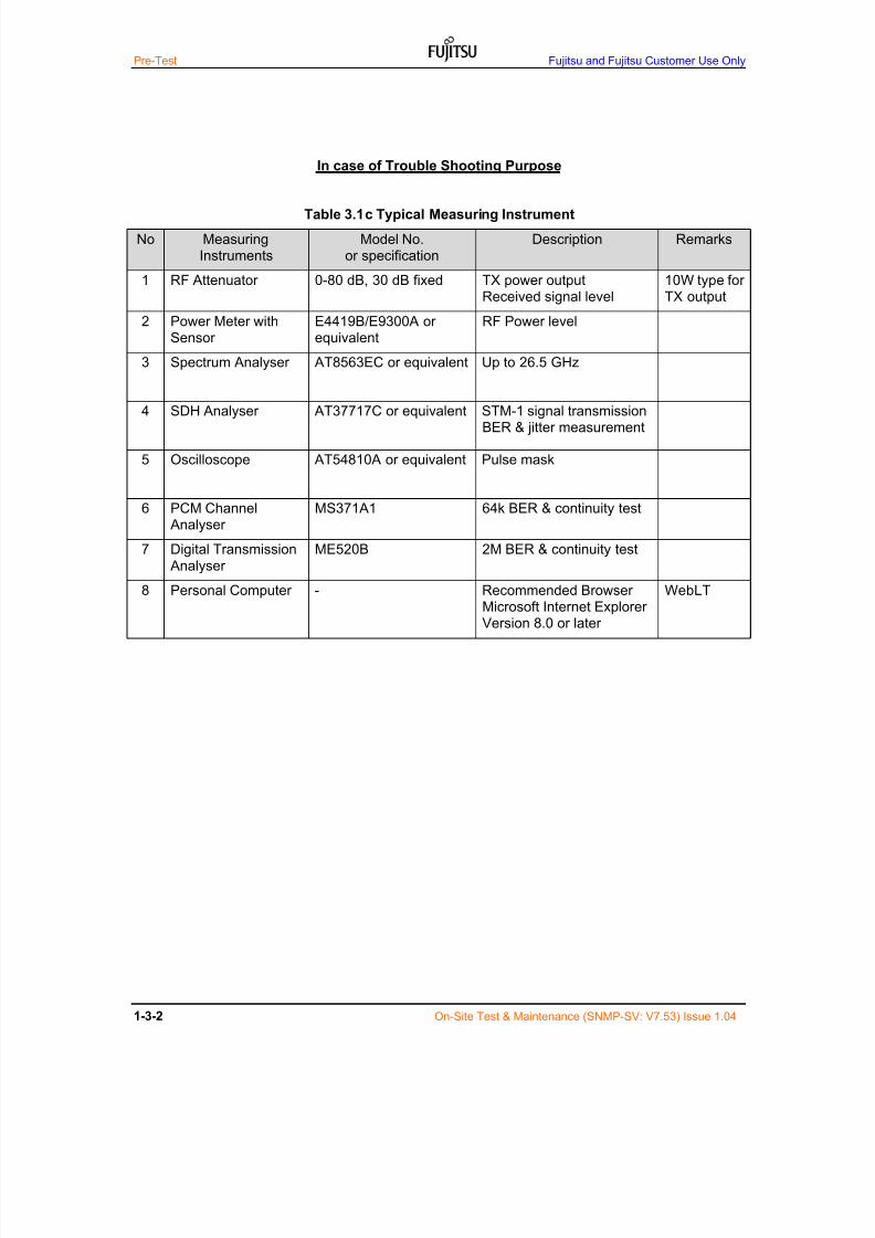
In case of Trouble Shooting Purpose
Table 3.1c Typical Measuring Instrument
No MeasuringInstruments
Model No.or specification
Description Remarks
1 RF Attenuator 0-80 dB, 30 dB fixed TX power outputReceived signal level
10W type forTX output
2 Power Meter withSensor
E4419B/E9300A orequivalent
RF Power level
3 Spectrum Analyser AT8563EC or equivalent Up to 26.5 GHz
4 SDH Analyser AT37717C or equivalent STM-1 signal transmissionBER & jitter measurement
5 Oscilloscope AT54810A or equivalent Pulse mask
6 PCM Channel Analyser
MS371A1 64k BER & continuity test
7 Digital Transmission
Analyser
ME520B 2M BER & continuity test
8 Personal Computer - Recommended BrowserMicrosoft Internet ExplorerVersion 8.0 or later
WebLT

7/24/2019 Frx-3e Test v7.55 Issue1.06 June2014
http://slidepdf.com/reader/full/frx-3e-test-v755-issue106-june2014 17/214
Fujitsu and Fujitsu Customer Use Only Table of Contents
On-Site Test & Maintenance (SNMP-SV: V7.55) Issue 1.06 i
Chapter 2 Hardware & Software Setting
1. Hardware Setting on Card1.1 Hardware Setting on SV 2-1-2
1.2 Hardware Setting on AUX INTF 2-1-6
1.3 Hardware Setting on GESW v1 2-1-8
1.4 Hardware Setting on GESW v2 2-1-9
2. Overview of WebLT (V7.55)
2.1 Application Version 2-2-1
2.2 Outline of WebLT 2-2-1
2.3 Menu Tree & Description 2-2-2
2.4 Provisioning Item 2-2-5
2.5 Condition 2-2-7
2.6 Control Item 2-2-11
2.7 Performance Monitor Item 2-2-12
2.8 Inventory 2-2-13
3. Initial Software Setting by License Key File
3.1 Initial Software Setting by License Key 2-3-1
3.2 Initial Software Start-up by License Key 2-3-2
3.3 Set-up Procedure 2-3-2

7/24/2019 Frx-3e Test v7.55 Issue1.06 June2014
http://slidepdf.com/reader/full/frx-3e-test-v755-issue106-june2014 18/214
Fujitsu and Fujitsu Customer Use Only Table of Contents
On-Site Test & Maintenance (SNMP-SV: V7.55) Issue 1.06 ii
This page intent ional ly left blank

7/24/2019 Frx-3e Test v7.55 Issue1.06 June2014
http://slidepdf.com/reader/full/frx-3e-test-v755-issue106-june2014 19/214
Fujitsu and Fujitsu Customer Use Only Hardware Setting
On-Site Test & Maintenance (SNMP-SV: V7.54) Issue1.05 2-1-1
1 Hardware Setting on Cards
Basic shelf cards are set and tuned at the factory and commissioning test is toassure the system performance.
There is no need to carry out any setting change or readjustment for Basicshelf cards.
Fujitsu strongly recommends not to change or re-adjust settings unless theerror performance degraded seriously because of equipment deterioration.
Following information is provided for very skilled technical staffs who mayhave any chances to change or re-adjust settings in some specialcircumstances.
NOTICE
Do not attempt to change or readjust settings of
Basic shelf cards unless seriously needed.
If needed, use the WebLT as the first priority.
7/24/2019 Frx-3e Test v7.55 Issue1.06 June2014
http://slidepdf.com/reader/full/frx-3e-test-v755-issue106-june2014 20/214
Hardware Setting Fujitsu and Fujitsu Customer Use Only
2-1-2 On-Site Test & Maintenance (SNMP-SV: V7.54) Issue1.05
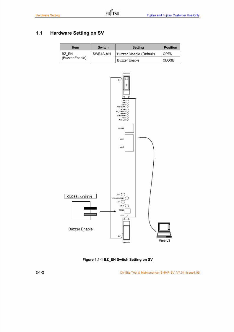
1.1 Hardware Setting on SV
Item Switch Setting Position
BZ_EN(Buzzer Enable)
SWB1A-bit1 Buzzer Disable (Default) OPEN
Buzzer Enable CLOSE
Figure 1.1-1 BZ_EN Switch Setting on SV
CLOSE OPEN
Buzzer Enable
Web LT

7/24/2019 Frx-3e Test v7.55 Issue1.06 June2014
http://slidepdf.com/reader/full/frx-3e-test-v755-issue106-june2014 21/214
Fujitsu and Fujitsu Customer Use Only Hardware Setting
On-Site Test & Maintenance (SNMP-SV: V7.54) Issue1.05 2-1-3
Figure 1.1-2 Optional RAB Module Installation on SV
RAB module assembly
(1) Metal spacing pipe x2
(2) RAB module x1(3) Fixing screw x4
There is a multi-pin connectorback of RAB module.
RAB module installation-1
(1) Metal spacing pipe installation on SV marked in white above: x2
Plug-in multi-pin connector forRAB module on SV
RAB module installation-2
(2) Plug-in RAB module to SV card using multi-connector
(3) Fix RAB module to SV card using fixing screws x2
7/24/2019 Frx-3e Test v7.55 Issue1.06 June2014
http://slidepdf.com/reader/full/frx-3e-test-v755-issue106-june2014 22/214
Hardware Setting Fujitsu and Fujitsu Customer Use Only
2-1-4 On-Site Test & Maintenance (SNMP-SV: V7.54) Issue1.05
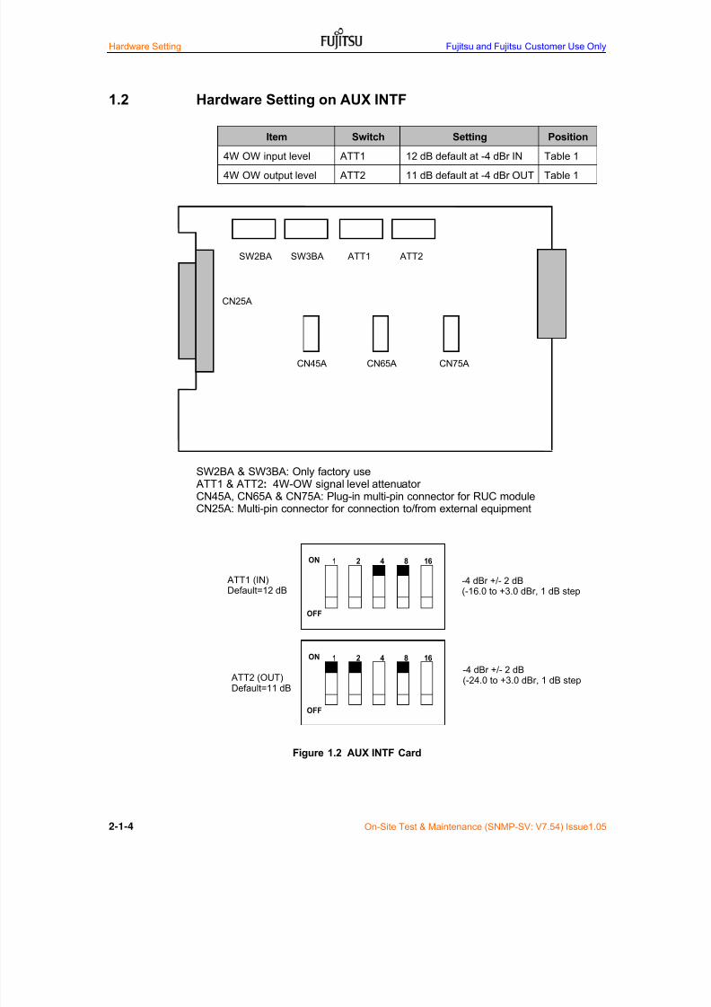
1.2 Hardware Setting on AUX INTF
Item Switch Setting Position
4W OW input level ATT1 12 dB default at -4 dBr IN Table 1
4W OW output level ATT2 11 dB default at -4 dBr OUT Table 1
SW2BA & SW3BA: Only factory use ATT1 & ATT2: 4W-OW signal level attenuatorCN45A, CN65A & CN75A: Plug-in multi-pin connector for RUC moduleCN25A: Multi-pin connector for connection to/from external equipment
Figure 1.2 AUX INTF Card
SW2BA SW3BA ATT1 ATT2
CN45A CN65A CN75A
CN25A
1 2 4 8 16
ATT C
ATT D
1 2 4 8 16
ATT A
ATT B
ON
OFF
ON
OFF
ATT1 (IN)Default=12 dB
ATT2 (OUT)Default=11 dB
-4 dBr +/- 2 dB(-16.0 to +3.0 dBr, 1 dB step
-4 dBr +/- 2 dB(-24.0 to +3.0 dBr, 1 dB step

7/24/2019 Frx-3e Test v7.55 Issue1.06 June2014
http://slidepdf.com/reader/full/frx-3e-test-v755-issue106-june2014 23/214
Fujitsu and Fujitsu Customer Use Only Hardware Setting
On-Site Test & Maintenance (SNMP-SV: V7.54) Issue1.05 2-1-5
Table 1. 4W Orderwire Input/Output Level Setting
Input Level (dBr)Setting of Attenuator
(ATT C, ATT D)Output Level (dBr)
Setting of Attenuator(ATT A and ATT B)
-16 0 Not applicable 0
-15 1 Not applicable 1
-14 2 Not applicable 2
-13 3 Not applicable 3
-12 4 +3 4
-11 5 +2 5
-10 6 +1 6
-9 7 0 7
-8 8 -1 8
-7 9 -2 9
-6 10 -3 10
-5 11 -4 11 (default)
-4 12 (default) -5 12
-3 13 -6 13
-2 14 -7 14
-1 15 -8 15
0 16 -9 16+1 17 -10 17
+2 18 -11 18
+3 19 -12 19
Not applicable 20 -13 20
Not applicable 21 -14 21
Not applicable 22 -15 22
Not applicable 23 -16 23
Not applicable 24 -17 24
Not applicable 25 -18 25
Not applicable 26 -19 26
Not applicable 27 -20 27
Not applicable 28 -21 28
Not applicable 29 -22 29
Not applicable 30 -23 30
Not applicable 31 -24 31

7/24/2019 Frx-3e Test v7.55 Issue1.06 June2014
http://slidepdf.com/reader/full/frx-3e-test-v755-issue106-june2014 24/214
Hardware Setting Fujitsu and Fujitsu Customer Use Only
2-1-6 On-Site Test & Maintenance (SNMP-SV: V7.54) Issue1.05
Optional Analog/G.703/V.11 module on AUX INTF
Note-1: VF/DGTL/V.11 module is plug-in’ed on AUX INTF card using CN45A, CN65A &CN75A and fixed by 2 screws. Detailed procedure is same as RAB module on SV.Note-2: Maximum number of RUC is 3 and mixture of VF/DGTL/V.11 module available.
Figure 1.2b RUC Module Installation on AUX INTF
VF Module DGTL Module V.11 Module

7/24/2019 Frx-3e Test v7.55 Issue1.06 June2014
http://slidepdf.com/reader/full/frx-3e-test-v755-issue106-june2014 25/214
Fujitsu and Fujitsu Customer Use Only Hardware Setting
On-Site Test & Maintenance (SNMP-SV: V7.54) Issue1.05 2-1-7
Analog Signal Level Setting when VF module is installed
Input level: -4 dBr +/- 2 dB (-16 to +3.0 dBr, 1 dB step)
Output level: -4 dBr +/- 2 dB (-24.0 to +3dBr, 1 dB step)
Figure 1.2c VF Module IN/OUT signal Level Setting on AUX INTF
1 2 4 8 16
ATT C
ATT D
1 2 4 8 16
ATT A
ATT B
ON
OFF
ON
OFF
ATT1B (IN)
ATT2B (IN)
ATT1B (IN)
Default=12 dB
ATT2B (OUT)Default=11 dB
7/24/2019 Frx-3e Test v7.55 Issue1.06 June2014
http://slidepdf.com/reader/full/frx-3e-test-v755-issue106-june2014 26/214
Hardware Setting Fujitsu and Fujitsu Customer Use Only
2-1-8 On-Site Test & Maintenance (SNMP-SV: V7.54) Issue1.05
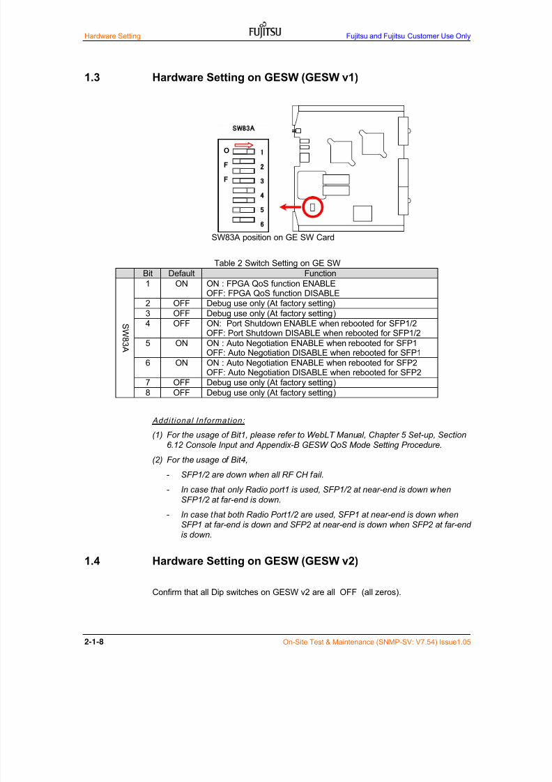
1.3 Hardware Setting on GESW (GESW v1)
SW83A position on GE SW Card
Addit ional Information:
(1) For the usage of Bit1, please refer to WebLT Manual, Chapter 5 Set-up, Section
6.12 Console Input and Appendix-B GESW QoS Mode Setting Procedure.
(2) For the usage of Bit4,
- SFP1/2 are down when all RF CH fail.
- In case that only Radio port1 is used, SFP1/2 at near-end is down when
SFP1/2 at far-end is down.
- In case that both Radio Port1/2 are used, SFP1 at near-end is down when
SFP1 at far-end is down and SFP2 at near-end is down when SFP2 at far-end
is down.
1.4 Hardware Setting on GESW (GESW v2)
Confirm that all Dip switches on GESW v2 are all“OFF
” (all zeros).
Table 2 Switch Setting on GE SW
Bit Default Function
SW83A
1 ON ON : FPGA QoS function ENABLEOFF: FPGA QoS function DISABLE
2 OFF Debug use only (At factory setting)
3 OFF Debug use only (At factory setting)
4 OFF ON: Port Shutdown ENABLE when rebooted for SFP1/2OFF: Port Shutdown DISABLE when rebooted for SFP1/2
5 ON ON : Auto Negotiation ENABLE when rebooted for SFP1
OFF: Auto Negotiation DISABLE when rebooted for SFP16 ON ON : Auto Negotiation ENABLE when rebooted for SFP2OFF: Auto Negotiation DISABLE when rebooted for SFP2
7 OFF Debug use only (At factory setting)
8 OFF Debug use only (At factory setting)
2
3
4
5
6
7
8
O
F
F
SW83A

7/24/2019 Frx-3e Test v7.55 Issue1.06 June2014
http://slidepdf.com/reader/full/frx-3e-test-v755-issue106-june2014 27/214
Fujitsu and Fujitsu Customer Use Only Hardware & Software Setting
On-Site Test & Maintenance (SNMP-SV: V7.55) Issue 1.06 2-2-1
2 Main Function of WebLT (SNMP-SV: V7.55)
2.1 Menu Tree and Menu Description when GESW v2 is installed
Figure 7.2 shows the menu tree and Table 2.1 shows menu description,
Figure 2.1 Menu Tree for GESW v2
Menu Tree when GESW v2 is set in the GESW setting menu.
Slot Config
RF Config
Modulation Config
CH Config
Service State
TX Setting
Menu
Condition Display
ALL
TRMD
BB INTF
COM
IF Response
Control RPS
Loopback
RCI
HK Delay Equalizer Select
Set Date RSPI
Revise Date RUC
Restart SV RPS (GP)
RPI RSC
DADE Adjust WS
ADJ Equipment Trace (SDH J0 byte)
ALS Trace (Data)
Order Wire Baseband Interface
ALS Setting
GE GESW Setting
Provisioning GE Composition Setting
GE Radio Port Setting
A B

7/24/2019 Frx-3e Test v7.55 Issue1.06 June2014
http://slidepdf.com/reader/full/frx-3e-test-v755-issue106-june2014 28/214
Hardware & Software Setting Fujitsu and Fujitsu Customer Use Only
2-2-2 On-Site Test & Maintenance (SNMP-SV: V7.55) Issue 1.06
Figure 2.1 Menu Tree for GESW v2 (Cont’d)
Note-*1: Skip to Procedure C.
Download Physical Inventory Analog Monitor Adjust
Download Severity List LED Mode
Upload SV/FIRM
Download Database ACT/DACT
STP Config
STP Status
Upload Severity List
Upload Database
Upload Lisence Key
History Control&Provisioning Login Setting
Download Condition HK Description
Upload FPGA/FIRM
Download Control&Provisioning RF Description
Download Performance CH Deascription
History & File
Threshold 1day Physical Inventory NE
Analog Monitor Physical Inventory Unit
Initial Registeor Network Setting (IP)
History Condition Network Setting (Others)
Data GP<1/2>-Wn GESW-2 (*1)
Threshold NA DCC/OW CH Setting
Threshold 15min Order Wire
A B
Performance Data GP<1/2>-P GESW-1 (*1)
7/24/2019 Frx-3e Test v7.55 Issue1.06 June2014
http://slidepdf.com/reader/full/frx-3e-test-v755-issue106-june2014 29/214
Fujitsu and Fujitsu Customer Use Only Hardware & Software Setting
On-Site Test & Maintenance (SNMP-SV: V7.55) Issue 1.06 2-2-3
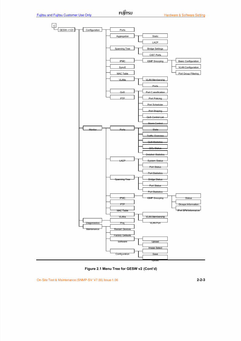
Figure 2.1 Menu Tree for GESW v2 (Cont’d)
C
GESW-<1/2> Configuration Ports
Aggregation Static
LACP
Spanning Tree Bridge Settings
CIST Ports
IPMC IGMP Snooping Basic Configuration
SyncE VLAN Configuration
Port Group Filtering
VLANs VLAN Membership
Ports
QoS Port Classification
PTP Port Policing
Port Scheduler
Port Shaping
QoS Control List
MAC Table
Storm Control
Monitor Ports State
Traffic Overview
QoS Statistics
QCL Status
Detailed Statistics
LACP System Status
Port Status
Port Statistics
Spanning Tree Bridge Status
Port Status
Port Statistics
IPMC IGMP Snooping Status
PTP Groups Information
MAC Table IPv4 SFM Information
VLANs VLAN Membership
Diagonostics Ping VLAN Port
Maintenance Restart Devices
Factory Defaults
Software Upload
Image Select
Configuration Save
Upload
7/24/2019 Frx-3e Test v7.55 Issue1.06 June2014
http://slidepdf.com/reader/full/frx-3e-test-v755-issue106-june2014 30/214
Hardware & Software Setting Fujitsu and Fujitsu Customer Use Only
2-2-4 On-Site Test & Maintenance (SNMP-SV: V7.55) Issue 1.06
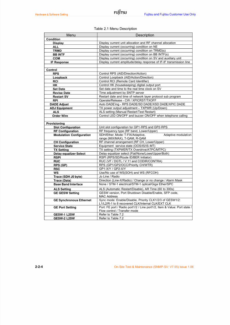
Table 2.1 Menu Description
Menu DescriptionCondition
Display Display current unit allocation and RF channel allocation
ALL Display current (occurring) condition on NE
TRMD Display current (occurring) condition on TRMD(s)
BB INTF Display current (occurring) condition on BB INTF(s)
COM Display current (occurring) condition on SV and auxiliary unit
IF Response Display current amplitude/delay response of IF-IF transmission line
Control
RPS Control RPS (AID/Direction/Action)
Loopback Control Loopback (AID/Action/Direction)
RCI Control RCI (Remote Card Identifier)
HK Control HK (housekeeping) digital output port
Set Date Set date and time to the real time clock on SV
Revise Date Time adjustment by SNTP server
Restart SV Restart date and time of network layer protocol sub program
RPI Operate/Release - CW / XPICRST/TXOFF
DADE Adjust Auto DADE’ing - RPS DADE/SD DADE/XSD DADE/XPIC DADE
ADJ Equipment TX power output adjustment – TXPWR (Up/Down)
ALS ALS setting (Manual Restart/Test Restart)
Order Wire Control LED ON/OFF and buzzer ON/OFF when telephone calling
Provisioning
Slot Configuration Unit slot configuration for GP1-RPS and GP2-RPS
RF Configuration RF frequency type (RF band, Lower/Upper)
Modulation Configuration SDH/Ether, Mode: T-FIX/Adaptive, Adaptive modulationrange (MIX/MAX), T-QAM, R-QAM
CH Configuration RF channel arrangement (RF CH, Lower/Upper)
Service State Equipment service state (OOS/IS/IS-MT)
TX Setting TX setting (TXPWER/TX Overdrive/ATPC/MTPC)
Delay equalizer Select Delay equalizer select (Flat/None/Lowe/Upper/Both)
RSPI RSPI (RPS/SD/Route ID/BER Initiator)
RUC RUC (VF / DGTL / V.11 and CODIR/CONTRA)
RPS (GP) RPS (GP1/GP2/OCC/Priority CH/WTR)
RSC GP1-X/Y / GP2-X/Y
WS Use/No use of WS(SOH) and WS (RFCOH)
Trace (SDH J0 byte) Jo Line / Radio
Trace (Data) Direction (Line-X/Radio) / Change or no change / Alarm Mask
Base Band Interface None / STM-1 electrical/STM-1 optical/Giga Ether/SPC
ALS Setting ALS (Automatic Restart/Disable), AR Time (60 to 300s)
GE GESW Setting GESW version, Port Shutdown Disable/Enable, SFP code,
MAC AddressGE Synchronous Ethernet Sync mode: Enable/Disable, Priority CLK1/2/3 of GESW1/2:L1/L2/R-1 to 8 recovered CLK/Internal CLK/EXT CLK
GE Port Setting Port: FE port / Radio port1/2 / Line port1/2, Item & Value: Port state /Flow control / Transfer mode
GESW-1 L2SW Refer to Table 7.2
GESW-2 L2SW Refer to Table 7.2
7/24/2019 Frx-3e Test v7.55 Issue1.06 June2014
http://slidepdf.com/reader/full/frx-3e-test-v755-issue106-june2014 31/214
Fujitsu and Fujitsu Customer Use Only Hardware & Software Setting
On-Site Test & Maintenance (SNMP-SV: V7.55) Issue 1.06 2-2-5
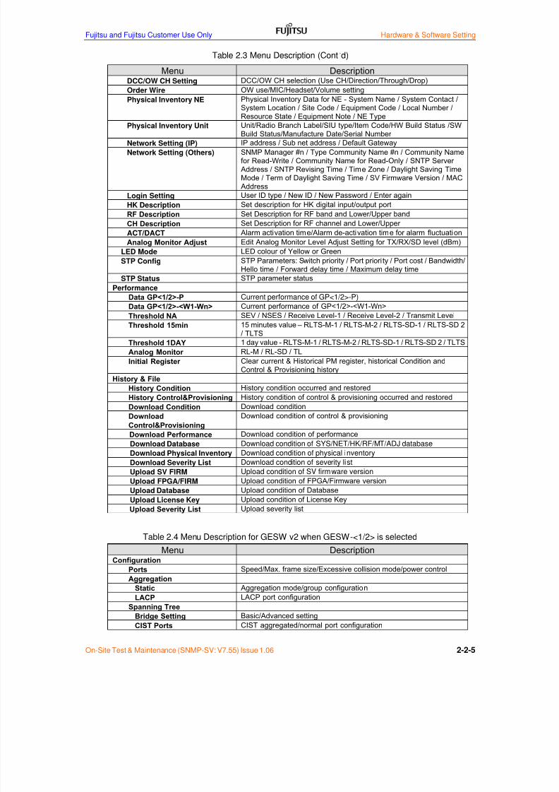
Table 2.3 Menu Description (Cont’d)
Menu DescriptionDCC/OW CH Setting DCC/OW CH selection (Use CH/Direction/Through/Drop)
Order Wire OW use/MIC/Headset/Volume setting
Physical Inventory NE Physical Inventory Data for NE - System Name / System Contact /System Location / Site Code / Equipment Code / Local Number /
Resource State / Equipment Note / NE TypePhysical Inventory Unit Unit/Radio Branch Label/SIU type/Item Code/HW Build Status /SWBuild Status/Manufacture Date/Serial Number
Network Setting (IP) IP address / Sub net address / Default Gateway
Network Setting (Others) SNMP Manager #n / Type Community Name #n / Community Namefor Read-Write / Community Name for Read-Only / SNTP Server Address / SNTP Revising Time / Time Zone / Daylight Saving TimeMode / Term of Daylight Saving Time / SV Firmware Version / MAC Address
Login Setting User ID type / New ID / New Password / Enter again
HK Description Set description for HK digital input/output port
RF Description Set Description for RF band and Lower/Upper band
CH Description Set Description for RF channel and Lower/Upper
ACT/DACT Alarm activation time/Alarm de-activation time for alarm fluctuation
Analog Monitor Adjust Edit Analog Monitor Level Adjust Setting for TX/RX/SD level (dBm)LED Mode LED colour of Yellow or Green
STP Config STP Parameters: Switch priority / Port priority / Port cost / Bandwidth/Hello time / Forward delay time / Maximum delay time
STP Status STP parameter status
Performance
Data GP<1/2>-P Current performance of GP<1/2>-P)
Data GP<1/2>-<W1-Wn> Current performance of GP<1/2>-<W1-Wn>
Threshold NA SEV / NSES / Receive Level-1 / Receive Level-2 / Transmit Level
Threshold 15min 15 minutes value – RLTS-M-1 / RLTS-M-2 / RLTS-SD-1 / RLTS-SD 2/ TLTS
Threshold 1DAY 1 day value - RLTS-M-1 / RLTS-M-2 / RLTS-SD-1 / RLTS-SD 2 / TLTS
Analog Monitor RL-M / RL-SD / TL
Initial Register Clear current & Historical PM register, historical Condition andControl & Provisioning history
History & File
History Condition History condition occurred and restored
History Control&Provisioning History condition of control & provisioning occurred and restored
Download Condition Download condition
Download
Control&Provisioning
Download condition of control & provisioning
Download Performance Download condition of performance
Download Database Download condition of SYS/NET/HK/RF/MT/ADJ database
Download Physical Inventory Download condition of physical inventory
Download Severity List Download condition of severity list
Upload SV FIRM Upload condition of SV firmware version
Upload FPGA/FIRM Upload condition of FPGA/Firmware versionUpload Database Upload condition of Database
Upload License Key Upload condition of License Key
Upload Severity List Upload severity list
Table 2.4 Menu Description for GESW v2 when GESW-<1/2> is selected
Menu DescriptionConfiguration
Ports Speed/Max. frame size/Excessive collision mode/power control
Aggregation
Static Aggregation mode/group configuration
LACP LACP port configuration
Spanning Tree
Bridge Setting Basic/Advanced setting
CIST Ports CIST aggregated/normal port configuration

7/24/2019 Frx-3e Test v7.55 Issue1.06 June2014
http://slidepdf.com/reader/full/frx-3e-test-v755-issue106-june2014 32/214
Hardware & Software Setting Fujitsu and Fujitsu Customer Use Only
2-2-6 On-Site Test & Maintenance (SNMP-SV: V7.55) Issue 1.06
Table 2.4 Menu Description for GESW v2 when GESW-<1/2> is selected (Cont’d)
Menu DescriptionConfiguration (Cont’d)
IPMC
IGMP Snooping
Basic Configuration IGMP snooping/Port Related Configuration
VLAN Configuration IGMP snooping VLAN configuration
Port Group Filtering IGMP snooping Port Group Filter Configuration
SyncE Clock source nomination and status, Clock selection mode and status
MAC Table MAC Address Table Configuration
VLANs
VLAN Membership VLAN Membership Table
Ports VLAN Port Configuration
QoS
Port Classification QoS Ingress Port Classification
Port Policing QoS Ingress Queue Policers
Port Scheduler QoS Ingress Port Schedulers
Port Shaping QoS Engress Port Tag Remarking
QoS Control List QoS Control List Configuration
Storm Control QoS Port Storm Control
PTP FTP External Clock Mode
Monitor
Ports
State Port Status
Traffic Overview Port Statistics Overview
QoS Statistics Queuing Counters
QCL Status QoS Control list status
Detailed Statistics Detailed Port Statistics Port 1 to Port8
LACP
System Status LACP System Status
Port Status LACP Port StatusPort Statistics LACP Port Statistics
Spanning Tree
Bridge Status STP Bridge
Port Status STP Port Status
Port Statistics STP Statistics
IPMC
IGMP Snooping
Status IGMP Snooping Status/Statistics/Router port
Groups Information IGMP Snooping Groups Information
IPv4 SFM Information IGMP SFM Information
PTP PTP External Clock Mode/PTP Clock Configuration
MAC Table MAC Address Table
VLANsVLAN Membership VLAN Membership Status for Combined Users
VLAN Port VLAN Port Status for Static User
Diagnostics
Ping ICMP Ping
Maintenance
Restart Devices Restart Devices, Yes/No
Factory Default Factory Default, Yes/No
Software
Upload Firmware Update
Image Select Software Image Selection
Configuration
Save Configuration Save
Upload Configuration Upload

7/24/2019 Frx-3e Test v7.55 Issue1.06 June2014
http://slidepdf.com/reader/full/frx-3e-test-v755-issue106-june2014 33/214
Fujitsu and Fujitsu Customer Use Only Hardware & Software Setting
On-Site Test & Maintenance (SNMP-SV: V7.55) Issue 1.06 2-2-7
2.2 Menu Tree and Menu Description when GESW v1 is installed
Figure 2.2 shows the menu tree and Table 7.3 shows menu description,
Figure 2.2 Menu Tree for GESW v1
Menu Tree when GESW v1 is set in the GESW Setting menu.Menu Slot Config
Condition Display RF Config
ALL Modulation Config
TRMD CH Config
BB INTF Service State
COM TX Setting
IF Response Delay Equalizer Select
Control RPS RSPI
Loopback RUC
RCI RPS (GP)
HK RSC
Set Date WS
GE Composition Setting
Revise Date Trace (SDH J0 byte)
Restart SV Trace (Data)
RPI Base Band Interface
Orderwire GE Synchronous Ethernet
Synchronous Ethernet GE Port Setting
GE Link Aggregation
DADE Adjust ALS Setting
ADJ Equipment GE GESW Setting
ALS
Aggregation Mode
Provisioning Static Aggregation
Dynamic Aggregation
GE MAC MAC Registration
GE Max Frame Setting MAC Table
Age Time
A B

7/24/2019 Frx-3e Test v7.55 Issue1.06 June2014
http://slidepdf.com/reader/full/frx-3e-test-v755-issue106-june2014 34/214
Hardware & Software Setting Fujitsu and Fujitsu Customer Use Only
2-2-8 On-Site Test & Maintenance (SNMP-SV: V7.55) Issue 1.06
Figure 2.2 Menu Tree for GESW v1
Upload Severity List
Upload FPGA/FIRM
Download Performance
Download Database
Download Physical Inventory
Download Severity List
History Control&Provisioning
Download Condition
Download Control&Provisioning
Upload SV/FIRM
Upload Database
Upload Licence Key
Analog Monitor GE Console Input DSCP
Initial Registor
QoS Tag Priority
History & File History Condition
Physical Inventory Unit
Network Setting (IP)
Network Setting (Others)
Data GESW<1/2> GE RSTP
Extra L2SW Data
Threshold NA
Threshold 15min GE QoS
DCC/OW CH Setting
A B
Order Wire
Physical Inventory NE
Performance Data GP<1/2>-P GE VLAN
Data GP<1/2>-Wn
Threshold 1day GE Rate Control
ID Setting
Item Setting
RSTP Configuration
Item Setting
RSTP Status
Item Setting
LED Mode
STP Config
STP Status
Login Setting
HK Description
RF Description
CH Description
ACT/DACT
Analog Monitor Adjust

7/24/2019 Frx-3e Test v7.55 Issue1.06 June2014
http://slidepdf.com/reader/full/frx-3e-test-v755-issue106-june2014 35/214
Fujitsu and Fujitsu Customer Use Only Hardware & Software Setting
On-Site Test & Maintenance (SNMP-SV: V7.55) Issue 1.06 2-2-9
Table 2.3 Menu Description
Menu DescriptionCondition
Display Display current unit allocation and RF channel allocation
ALL Display current (occurring) condition on NE
TRMD Display current (occurring) condition on TRMD(s)
BB INTF Display current (occurring) condition on BB INTF(s)
COM Display current (occurring) condition on SV and auxiliary unit
IF Response Display current amplitude/delay response of IF-IF transmission line
Control
RPS Control RPS (AID/Direction/Action)
Loopback Control Loopback (AID/Action/Direction)
RCI Control RCI (Remote Card Identifier)
HK Control HK (housekeeping) digital output port
Set Date Set date and time to the real time clock on SV
Revise Date Time adjustment by SNTP server
Restart SV Restart date and time of network layer protocol sub program
RPI Operate/Release - CW / XPICRST/TXOFF
DADE Adjust Auto DADE’ing - RPS DADE/SD DADE/XSD DADE/XPIC DADE
ADJ Equipment TX power output adjustment – TXPWR (Up/Down)
ALS ALS setting (Manual Restart/Test Restart)
Order Wire Control LED ON/OFF and buzzer ON/OFF when telephone calling
Synchronous Ethernet Control clock priority of GESW1/2: Auto, priority1/2/3 clock
Provisioning
Slot Configuration Unit slot configuration for GP1-RPS and GP2-RPS
RF Configuration RF frequency type (RF band, Lower/Upper)
Modulation Configuration SDH/Ether, Mode: T-FIX/Adaptive, Adaptive modulation range(MIX/MAX), T-QAM, R-QAM
CH Configuration RF channel arrangement (RF CH, Lower/Upper)
Service State Equipment service state (OOS/IS/IS-MT)
TX Setting TX setting (TXPWER/TX Overdrive/ATPC/MTPC)
Delay equalizer Select Delay equalizer select (Flat/None/Lowe/Upper/Both)
RSPI RSPI (RPS/SD/Route ID/BER Initiator)
RUC RUC (VF / DGTL / V.11 and CODIR/CONTRA)
RPS (GP) RPS (GP1/GP2/OCC/Priority CH/WTR)
RSC GP1-X/Y / GP2-X/Y
WS Use/No use of WS(SOH) and WS (RFCOH)
Trace (SDH J0 byte) Jo Line / Radio
Trace (Data) Direction (Line-X/Radio) / Change or no change / Alarm Mask
Base Band Interface None / STM-1 electrical/STM-1 optical/Giga Ether/SPC
ALS Setting ALS (Automatic Restart/Disable), AR Time (60 to 300s)
GE GESW Setting GESW version, Port Shutdown Disable/Enable, SFP code,MAC Address
GE Composition Setting R-n port connection on GESW1/2: Disable/RadioPort1/2, Line porton GESW1/2: Disable/Enable, EXT CLK on GESW1/2:Disable/Enable
GE Synchronous Ethernet Sync mode: Enable/Disable, Priority CLK1/2/3 of GESW1/2:L1/L2/R-1 to 8 recovered CLK/Internal CLK/EXT CLK
GE Port Setting Port: FE port / Radio port1/2 / Line port1/2, Item & Value: Port state /Flow control / Transfer mode
GE Link Aggregation
Aggregation Mode Aggregation mode: Static / Dynamic / XOR
Static Aggregation Control: Add / Delete, Group port: Group port1/2,FE port / Radio port1/2 / Line port1/2: Disable/Enable
Dynamic Aggregation Port: FE port / Radio port1/2 / Line port1/2
Item Value: Protocol / Key value

7/24/2019 Frx-3e Test v7.55 Issue1.06 June2014
http://slidepdf.com/reader/full/frx-3e-test-v755-issue106-june2014 36/214
Hardware & Software Setting Fujitsu and Fujitsu Customer Use Only
2-2-10 On-Site Test & Maintenance (SNMP-SV: V7.55) Issue 1.06
Table 2.3 Menu Description (Cont’d)
Menu DescriptionGE MAC
MAC Registration Control: Add / Delete, VLAN ID: 1-5, Port: FE / Radio 1/2 / Line 1/2
MAC Table VLAN ID: 1-5
Age Time Set-up: 0 –
65535
GE Max Frame Setting Port: FE / Radio1/2 / Line1/2, Max frame size: 1518 – 9600
GE VLAN
ID Setting Control: Add/Delete, VLAN ID: 1-4096, Port: Disable/Enable
Item Setting Item: VLAN aware/Ingress filtering/Packet type/Port VLAN IDValue: Disable/Enable or All/Tagged Only or NONE/1/2
GE RSTP
RSTP Configuration Item: System priority/Hello time/Max age/Forward delay/Forced version/Port aggregations
Item Setting Port: FE / Radio1/2 / Line1/2, Item: Port Protocol/Port edge/Port pathcost, Value: Disable/Enable etc.
RSTP Status -
GE QoS
Item Setting Port: FE / Radio1/2 / Line1/2, Item: QoS mode/QoS default/QoS userpriority, Value for each item
QoS Tag Priority Port: FE / Radio1/2 / Line1/2,Tag: 0-7, Priority: Low/Normal/Medium/High
DSCP DSCP: 0-63, Priority: Low/Normal/Medium/High
GE Rate Control Port: FE / Radio1/2 / Line1/2, Item: Policer/Shaper,Value: 128-3968 kbps, No limit
GE Console Input CLI command string
DCC/OW CH Setting DCC/OW CH selection (Use CH/Direction/Through/Drop)
Order Wire OW use/MIC/Headset/Volume setting
Physical Inventory NE Physical Inventory Data for NE - System Name / System Contact /System Location / Site Code / Equipment Code / Local Number /Resource State / Equipment Note / NE Type
Physical Inventory Unit Unit/Radio Branch Label/SIU type/Item Code/HW Build Status /SWBuild Status/Manufacture Date/Serial Number
Network Setting (IP) IP address / Sub net address / Default Gateway
Network Setting (Others) SNMP Manager #n / Type Community Name #n / Community Namefor Read-Write / Community Name for Read-Only / SNTP Server Address / SNTP Revising Time / Time Zone / Daylight Saving TimeMode / Term of Daylight Saving Time / SV Firmware Version / MAC Address
Login Setting User ID type / New ID / New Password / Enter again
HK Description Set description for HK digital input/output port
RF Description Set Description for RF band and Lower/Upper band
CH Description Set Description for RF channel and Lower/Upper
ACT/DACT Alarm activation time/Alarm de-activation time for alarm fluctuation
Analog Monitor Adjust Edit Analog Monitor Level Adjust Setting for TX/RX/SD level (dBm)
LED Mode LED colour of Yellow or Green
STP Config STP Parameters: Switch priority / Port priority / Port cost / Bandwidth/Hello time / Forward delay time / Maximum delay time
STP Status STP parameter status
7/24/2019 Frx-3e Test v7.55 Issue1.06 June2014
http://slidepdf.com/reader/full/frx-3e-test-v755-issue106-june2014 37/214
Fujitsu and Fujitsu Customer Use Only Hardware & Software Setting
On-Site Test & Maintenance (SNMP-SV: V7.55) Issue 1.06 2-2-11
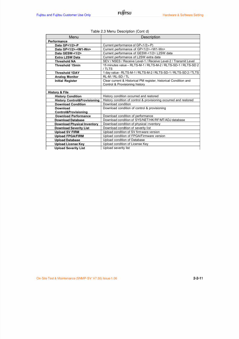
Table 2.3 Menu Description (Cont’d)
Menu DescriptionPerformance
Data GP<1/2>-P Current performance of GP<1/2>-P)
Data GP<1/2>-<W1-Wn> Current performance of GP<1/2>-<W1-Wn>
Data GESW-<1/2> Current performance of GESW-<1/2> L2SW data
Extra L2SW Data Current performance of L2SW extra data
Threshold NA SEV / NSES / Receive Level-1 / Receive Level-2 / Transmit Level
Threshold 15min 15 minutes value – RLTS-M-1 / RLTS-M-2 / RLTS-SD-1 / RLTS-SD 2/ TLTS
Threshold 1DAY 1 day value - RLTS-M-1 / RLTS-M-2 / RLTS-SD-1 / RLTS-SD 2 / TLTS
Analog Monitor RL-M / RL-SD / TL
Initial Register Clear current & Historical PM register, historical Condition andControl & Provisioning history
History & File
History Condition History condition occurred and restored
History Control&Provisioning History condition of control & provisioning occurred and restored
Download Condition Download condition
Download
Control&Provisioning
Download condition of control & provisioning
Download Performance Download condition of performance
Download Database Download condition of SYS/NET/HK/RF/MT/ADJ database
Download Physical Inventory Download condition of physical inventory
Download Severity List Download condition of severity list
Upload SV FIRM Upload condition of SV firmware version
Upload FPGA/FIRM Upload condition of FPGA/Firmware version
Upload Database Upload condition of Database
Upload License Key Upload condition of License Key
Upload Severity List Upload severity list

7/24/2019 Frx-3e Test v7.55 Issue1.06 June2014
http://slidepdf.com/reader/full/frx-3e-test-v755-issue106-june2014 38/214
Hardware & Software Setting Fujitsu and Fujitsu Customer Use Only
2-2-12 On-Site Test & Maintenance (SNMP-SV: V7.55) Issue 1.06
2.3 Condition and Description List
Table 2-4 shows the condition item and description list.
Table 2-4 Condition Item and Description List
1 PSFAIL PS Failure CR CR
2 CARD-FAIL Card Failure CR MN
3 RMVD Card is removed CR NA
4 MISMOUNT Card is mismounted CR MN
5 RCI Remote Card Identifier - NA
6 TX FLR TX Block Failure CR MN
7 TCA-TLTS-15M Threshold Crossing Alert (TLTS-15m) - NA
8 TCA-TLTS-24H Threshold Crossing Alert (TLTS-24h) - NA
9 TCA-RLTS-M-1-15M Threshold Crossing Alert (RLTS-M-1-15m) - NA
10 TCA-RLTS-M-1-24H Threshold Crossing Alert (RLTS-M-1-24h) - NA
11 TCA-RLTS-M-2-15M Threshold Crossing Alert (RLTS-M-2-15m) - NA
12 TCA-RLTS-M-2-24H Threshold Crossing Alert (RLTS-M-2-24h) - NA
13TCA-RLTS-SD-1-15M Threshold Crossing Alert (RLTS-SD-1-15m)
- NA14 TCA-RLTS-SD-1-24H Threshold Crossing Alert (RLTS-SD-1-24h) - NA
15 TCA-RLTS-SD-2-15M Threshold Crossing Alert (RLTS-SD-2-15m) - NA
16 TCA-RLTS-SD-2-24H Threshold Crossing Alert (RLTS-SD-2-24h) - NA
17 ACTCW Carrier Wave Control in Active - NA
18 XPIC-OFF XPIC is OFF Control in Active - NA
19 SD-RCV-DN SD RX Received Level Down (BER=1.0E-3) MJ NR
20 MN-RCV-DN Main RX Received Level Down (BER=1.0E-3) MJ NR
21 LOF Loss of Frame CR NR
22 UAS-RP Unavailable State (RP) CR NR
23 TCA-RP-BBE15M Threshold Crossing Alert (RP-BBE-15m) - NA
24 TCA-RP-ES15M Threshold Crossing Alert (RP-ES-15m) - NA
25 TCA-RP-SES15M Threshold Crossing Alart (RP-SES-15m) - NA
26 TCA-RP-BBE24H Threshold Crossing Alert (RP-BBE-24H) - NA27 TCA-RP-ES24H Threshold Crossing Alert (RP-ES-24H) - NA
28 TCA-RP-SES24H Threshold Crossing Alart (RP-SES-24H) - NA
29 TCA-OFS15M Threshold Crossing Alert (OFS-15m) - NA
30 TCA-OFS24H Threshold Crossing Alart (OFS-24H) - NA
31 RADRM Radio Route ID Mismatch CR NR
32 RP-ERR-BP Excessive Bit Error Rate (BP Before FEC) - NR
33 SN-DEGRADE SN Degradation CR MN
34 XPIC-LOS-MN Loss of Signal in XPIC (MN XIF) MJ NR
35 XPIC-LOS-SD Loss of Signal in XPIC (SD IF) MJ NR
36 PSFAIL PS Failure CR CR
37 CARD-FAIL Card Failure CR MN
38 RMVD Card is removed CR NA
39 MISMOUNT Card is Mismounted CR MN40 RCI Remote Card Identifier - NA
41 FRCD Card is Forced Switched - NA
42 LOF Loss of Frame CR -
43 STIM Section Trace ID Mismatch CR -
44 UAS-B1 Unavailable State (B1) CR NR
45 TCA-B1-BBE15M Threshold Crossing Alert (B1-BBE-15m) - NA
46 TCA-B1-ES15M Threshold Crossing Alert (B1-ES-15m) - NA
47 TCA-B1-SES15M Threshold Crossing Alert (B1-SES-15m) - NA
48 TCA-B1-BBE24H Threshold Crossing Alert (B1-BBE-24h) - NA
49 TCA-B1-ES-24H Threshold Crossing Alert (B1-ES-24h) - NA
50 TCA-B1-SES24H Threshold Crossing Alert (B1-SES-24h) - NA
51 TCA-OFS15M Threshold Crossing Alert (OFS-15m) - NA
52 TCA-OFS24H Threshold Crossing Alert (OFS-24h) - NA
53 LOOPBACK Loopback in Active Condition - NA
No Card AID Type Condition Type Status Description SA NSA
TRMD
EQPT
RSPI
CNCT
Baseband
EQPT
STM1RS

7/24/2019 Frx-3e Test v7.55 Issue1.06 June2014
http://slidepdf.com/reader/full/frx-3e-test-v755-issue106-june2014 39/214
Fujitsu and Fujitsu Customer Use Only Hardware & Software Setting
On-Site Test & Maintenance (SNMP-SV: V7.55) Issue 1.06 2-2-13
Table 2-4 Condition Item and Description List (Cont’d)
54 CARD-FAIL Card Failure - MJ
55 RCI Remote Card Identifier - NA
56 ACTACO Alarm Cut Off in Act ive Condition - NA
57COMM-FAIL GP1R Communication Fail GP1-R
- MN58 COMM-FAIL GP1L Communication Fail GP1-L - MN
59 COMM-FAIL GP2R Communication Fail GP1-R - MN
60 COMM-FAIL GP2L Communication Fail GP2-L - MN
61 VENT-FAIL Ventilation Failure - WR
62 WS LOS Loss of Signal - MN
63 RSC LOF Loss of Frame - MN
64 LOPS Loss of Protection Signal - MN
65 SEINT-FAIL Serial Interface Failure CR
66 HK IN1 HK IN1 - MN
67 HK IN2 HK IN2 - MN
68 HK IN3 HK IN3 - MN
69 HK IN4 HK IN4 - MN
70 HK IN5 HK IN5 - MN
71 HK IN6 HK IN6 - MN72 HK IN7 HK IN7 - MN
73 HK IN8 HK IN8 - MN
74 HK IN9 HK IN9 - MN
75 HK IN10 HK IN10 - MN
76 HK IN11 HK IN11 - MN
77 HK IN12 HK IN12 - MN
78 HK IN13 HK IN13 - MN
79 HK IN14 HK IN14 - MN
80 HK IN15 HK IN15 - MN
81 HK IN16 HK IN16 - MN
82 HK OUT1 HK OUT1 - MN
83 HK OUT2 HK OUT2 - MN
84 HK OUT3 HK OUT3 - MN
85 HK OUT4 HK OUT4 - MN86 HK OUT5 HK OUT5 - MN
87 HK OUT6 HK OUT6 - MN
88 HK OUT7 HK OUT7 - MN
89 HK OUT8 HK OUT8 - MN
90 LKO-BSW Lockout of BSW - NA
91 LKO-USW Lockout of USW - NA
92 LKO-BSW FEND Lockout of BSW (FEND) - NA
93 SWREQ-BSW Switch Request in BSW - NR
94 SWREQ-USW Switch Request in USW - NR
95 SW-FAIL BSW Switching Failure in BSW - MJ
96 SW-FAIL USW Switching Failure in USW - MJ
97 FORCE-BSW Forced Switch of BSW - NA
98 FORCE-USW Forced Switch in USW - NA
99 MAN-BSW Manual Switch in BSW - NA100 MAN-USW Manual Switch in USW - NA
101 T-P BSW Traffic to Protection by BSW - NA
102 T-P USW Traffic to Protection by USW - NA
103 FORCE-BSW FEND Forced Switch of BSW (FEND) - NA
104 FORCE-USW FEND Forced Switch of USW (FEND) - NA
105 PRI-CH MIS Priority Channel Mismatch - NA
106 PS-FAIL PS Failure - MN
107 RCI Remote Card Identifier - NA
108 RUC LOS Loss of Signal - MN
109 CARD-FAIL Card Failure CR -
110 RMVD Card is Removed CR -
111 MISMOUNT Card is Mismatched CR -
112 RCI Remote Card Identifier - NA
113 LINK-DOWN R Radio Link Down - MN114 LINK-DOWN L Line Link Down CR -
115 BW-REDUCED Bandwidth Reduced CR MN
116 CLK-DOWN External Clock Down CR MN
Status Description SA
CONT
RPS
No Card AID Type Condition Type
Common
(AUX)
EQPT
Common
(GESW)
EQPT
Ether
NSA
Common
(SV)
EQPT
CNCT
ENV

7/24/2019 Frx-3e Test v7.55 Issue1.06 June2014
http://slidepdf.com/reader/full/frx-3e-test-v755-issue106-june2014 40/214
Hardware & Software Setting Fujitsu and Fujitsu Customer Use Only
2-2-14 On-Site Test & Maintenance (SNMP-SV: V7.55) Issue 1.06
2.4 Control Item and Description List
Table 2-5 shows the maintenance/Operation item and description.
Table 2-5 Control Item and Item Description
Note: For GESW v2, Synchronous Ethernet menu is not applicable.
RPS GP<1/2>- Direction Uni-Direction/Bi-Direction
<P, W1-W16> Action Operate Manual/Operate Forced/
Operate Lockout/Release Manual/
Release Forced/Release Lockout
Loopback GP<1/2>- Direction Line-X/Line-Y/Radio
<P, W1-W16> Action Operate/Release
RCI GP<1/2>- AID GP<1/2>-<P, W1-W16>-TRMD/
<P, W1-W16> GP<1/2>-<P, W1-W16>-BB INTF-X/
GP<1/2>-<P, W1-W16>-BB INTF-Y/
ASV/AUX1/AUX2/GESW1/GESW2/
Release ALL
HK HKO-<1-8> Action ON/OFF
Set Date - Year Range: 2002 to 2037
Month Range: 1 to 12
Day Range: 1-31
Hour Range: 0 to 23
Minute Range: 00 to 59
Second Range: 00 to 59Revise Date - Operate
Restart SV - Year Range: 2002 to 2037
Month Range: 1 to 12
Day Range: 1-31
Hour Range: 0 to 23
Minute Range: 00 to 59
Second Range: 00 to 59
Boot Select ACT/STBY
RPI GP<1/2>- Command CW/XPICRST/TXOFF
<P, W1-W16> Action Operate/Release
DADE Adjust GP<1/2>- DADE Adjust SD DADE/XSD DADE/XPIC DADE/<P, W1-W16> BPSDADE
ADJ Equipm ent GP<1/2>- TXPWR UP/DOWN
<P, W1-W16>
ALS GP<1/2>- ALS Manual Restart/Test Restart
<P,W1-W16>-
(X/Y>
Order Wire - Call ON ON/OFF
Synchronous Ethernet GESW-<1/2> Priority Select Auto/Priority1/Priority2/Priority3
Control AID Keyword Domain

7/24/2019 Frx-3e Test v7.55 Issue1.06 June2014
http://slidepdf.com/reader/full/frx-3e-test-v755-issue106-june2014 41/214
Fujitsu and Fujitsu Customer Use Only Hardware & Software Setting
On-Site Test & Maintenance (SNMP-SV: V7.55) Issue 1.06 2-2-15
2.5 Provisioning Item and Description List for GESW v2
Table 7-6 shows the Set-up item and description list for GESW v2.
Table 7-6 Provisioning Item and Description List for GESW v2
Table 7-4 Set-up Item and Description List for GESW v2 (Cont’d)
Slot Configuration GP<1/2>- Flexible Slot Allocation Mode Enable/Disable
<P,W1-W16> Slot al location for fixed mode Slot 1-8 for GP1 & s lo t 9-16 for GP2
Slot allocation for flexible mode Slot 1 for GP1-P, slot 9 or 16 for GP2-P
Other slot is free to allocate for GP1/2
RF Configuration GP1/GP2 RF band & type 4 to 13 GHz band & Type
<P,W1-W16> independently for GP1/2, P, W1 to W16
Modulation Configuration GP1/GP2- SDH/Ether SDH / Ether
<P, W1-W16> Mode T-FIX / Adaptive
Adaptive Modulation Range(MAX/MIN) QPSK/8/16/32/64/128/256/512QAM
T-QAM QPSK/8/16/32/64/128/256/512QAM
R-QAM QPSK/8/16/32/64/128/256/512QAM
CH Configuration GP<1/2>- RF channel No. CH1 to CH18 & Lower/Upper
<P,W1-W16> independently for GP1/2, P, W1 to W16
Service State GP<1/2>- Service state IS/OOS/IS-MT
<P,W1-W16>
TX Setting GP<1/2>- TX power NORMAL POWER/HIGH POWER
<P,W1-W16> TX Overdrive Enable/Disable
TPC ATPC-65 dBm/ATPC-55 dBm/
ATPC-45 dBm/MTPC
MTPC +2 to -20 dB, 1 dB-step
Delay Equalizer Select GP<1/2>- Adjacent channel allocation None/Lower/Upper/Both
<P,W1-W16>
RSPI GP<1/2>- RPS Enable/Disable
<P,W1-W16> Space Diversity Enable/Disable
XPIC Enable/DisableRoute ID 0 to 15
BER 1.0E-3/5.0E-4/1.0E-4/5.0E-5/
1.0E-5/5.0E-6/1.0E-6
RUC GP<1/2>- 64K IF (only for G.703 interface) Co-directional/directional
RUC-<1-3>
RPS (GP) GP1/GP2 GP GP1/GP2
OCC Enable/Disable
Priority Ch W1 to W16/Disable
Wait To Restore None/1 to 20
RSC GP1/GP2 GP1-X Disable/GP1-P, W1-W16
GP1-Y Disable/GP1-P, W1-W16
GP2-X Disable/GP2-P, W1-W16
GP2-Y Disable/GP2-P, W1-W16
WS GP<1/2>- WS(SOH) Enable/Disable
<P, W1-W16> WS(RFCOH) Enable/Disable
Trace (SDH J0 byte) GP<1/2>- J0 Line-X Through/Section Trace
<P, W1-W16> J0 Line-Y Through/Section Trace/-
Jo Radio Through/Section Trace
Trace (Data) GP<1/2>- Direction Line-X/Radio
<P, W1-W16> Data Change/No change
Send Data 15 alphanumerical characters
Expect Data 15 alphanumerical characters
Alarm Mask Enable/Disable
Base Band Interface GP<1/2>- BaseBand Interface None/STM-1 electrical/STM-1 optical
<P, W1-W16> Giga Ether/SPC ALS Setting GP<1/2>- ALS Automatic Restart/Disable
<P, W1-W16>- AR Time 60s/120s/180s/240s/300s
<X/Y>
Provisioning AID Keyword Domain

7/24/2019 Frx-3e Test v7.55 Issue1.06 June2014
http://slidepdf.com/reader/full/frx-3e-test-v755-issue106-june2014 42/214
Hardware & Software Setting Fujitsu and Fujitsu Customer Use Only
2-2-16 On-Site Test & Maintenance (SNMP-SV: V7.55) Issue 1.06
Table 2-6 Provisioning Item and Description List for GESW v2 (Cont’d)
GE GESW Setting GESW1/2 GESW version GESW v1/GESW v2
Port Shutdown Disable/Enable
SFP code -
MAC address -
GE Com position Setting GESW1/2 GESW-1/2-R-1/2/3/4/5/6/7/8 RadioAgg1/RadioAgg2
GESW-1/2-L-1/2/3/4 Enable/Disable
GESW1/2 EXT CLK Enable/Disable
GE Radio Port Setting GESW1/2 GESW-1/2-RadioPort1/2/3/4 RadioAgg/Priority/Ratio
RadioAggregation RadioAgg1/RadioAgg2
Priority -/Priority1/Priority2/Priority3/Priority4
Ratio -/10%/20%/30%/40%/50%
GESW-1 L2SW For details, refer to Appendix-A
GESW-2 L2SW For details, refer to Appendix-A
DCC/OW CH Setting GP1/2 Use Channel W1/W3/W5/W7
DCC/OW DCC/OW
Direction Line/Radio
Use Through/Drop
Order Wire - OW Enable Enable/Disable
MIC/Headset MIC/Headset
Volume Minimum/1 to 9/Maximum
Physical Inventory NE - System Name Max. 60 alphanumerical characters
System Contact Max. 60 alphanumerical characters
System Location Max. 60 alphanumerical characters
Site Code Max. 9 alphanumerical charactersEquipment Code Max. 5 alphanumerical characters
Local Number Max. 6 alphanumerical characters
Resource State Max. 9 alphanumerical characters
Equipment Note Max. 60 alphanumerical characters
NE Type Read Only
Phys ical Inventory Unit GP<1/2>- UNIT GP1/2-P, W1-W16, SV, GESW, AUXINTF
<P, W1-W7> Radio Branch Label Max. 32 alphanumerical characters
SIU Type -
Hardware Build Status -
Software Build Status -
Manufacture Date -
Serial Number 6 digits
Provisioning AID Keyword Domain

7/24/2019 Frx-3e Test v7.55 Issue1.06 June2014
http://slidepdf.com/reader/full/frx-3e-test-v755-issue106-june2014 43/214
Fujitsu and Fujitsu Customer Use Only Hardware & Software Setting
On-Site Test & Maintenance (SNMP-SV: V7.55) Issue 1.06 2-2-17
Table 2-6 Provisioning Item and Description List for GESW v2 (Cont’d)
Network Setting (IP) - IP default: 192.168.0.10
Sub Netmask default: 255.255.255.0
Gate Way default: 192.168.0.1
Network Setting (Others) - SNMP Trap Mode Bipmap/Object
SNMP Manager#1/#2/#3 default: 0.0.0.0
Type of Community Name#1/#2/#3 Read-Write/Read-Only
Communication Name for Sysmanager
Community Name for Read-Write
Community Name for Read-Only
Standard Trap Enable/Disable
SNTP Server Address default: 0.0.0.0
SNMP Revising Time (Range: 0 to 23) : (Range: 0 to 59)
Last Synchronization Time y, m, d - h, m, sTime Zone (Range: 0 to 13) : (Range: 0/15/30/45)
Daylight Saving Time Mode Enable/Disable
DTS Start Month/Day/Hour
DTS End Month/Day/Hour
MAC Address
Login Setting - New Password 12 alphanumeric characters
Enter Password Again 12 alphanumeric characters
HK Description I-<1-16> IN/OUT IN/OUT
O-<1-8> No. 1 to 16 for DI (Digitai input, SV)
1-8 for DO (Digital output, CONT)
Description Max. 10 alphanumerical characters
RF Description - RF Type 4 to 13 GHz, Lower/Upper Description max. 16 alphanumerical characters
CH Description - RF CH No. CH1 to CH16, Lower/Upper
Description max. 8 alphanumerical characters
ACT/DACT RSPI/STM1/RPS ACT 0 to 10
DACT 0 to 10
Analog Monitor Ajus t GP<1/2>- RL-M -10 to +10
<P, W1-W16> RL-SD -10 to +10
TL -10 to +10
LED Mode - Provisioning value Yellow/Green
STP Configuration - Enable Status Enable/Disable
Switch Priority 0 to 65535
Port Priority o to 255
Port Cost o to 65535
Bandwidth
Hello Time 1 to 10
Forward Delay Time 4 to 30
Maximum Aging Time 6 to 40
STP Status - STP Status Root Switch Priority/MAC Address
Port State/Switch Status/Topology
Provisioning AID Keyword Domain

7/24/2019 Frx-3e Test v7.55 Issue1.06 June2014
http://slidepdf.com/reader/full/frx-3e-test-v755-issue106-june2014 44/214
Hardware & Software Setting Fujitsu and Fujitsu Customer Use Only
2-2-18 On-Site Test & Maintenance (SNMP-SV: V7.55) Issue 1.06
2.6 Provisioning Item and Description List for GESW v1
Table 2-7 shows the Set-up item and description list for GESW v1.
Table 2-7 Provisioning Item and Description List for GESW v1
Slot Configuration GP<1/2>- Flexible Slot Allocation Mode Enable/Disable
<P,W1-W16> Slot a lloca tion fo r fixed mode Slot 1 -8 fo r GP1 & s lo t 9 -16 fo r GP2
Slot al location for flexible mode Slot 1 for GP1-P & slo t 9 or 16 for GP2-P
Other slot is free to allocate for GP1/2
RF Configuration GP1/GP2 RF banf & Type 4 to 13 GHz band & type
<P,W1-W16> independently for GP1/2, P, W1-16
Modulation Configuration GP1/GP2- SDH/Ether SDH / Ether
<P, W1-W16> Mode T-FIX / Adaptive
Adaptive Modulation Range(MAX/MIN) QPSK/8/16/32/64 /128/256/512QAM
T-QAM QPSK/8/16/32/64/128/256/512QAM
R-QAM QPSK/8/16/32/64/128/256/512QAM
CH Configuration GP<1/2>- RF channel number CH1 to CH18 & Lower/Upper
<P,W1-W16> independently for GP1/2, P, W1-16
Service State GP<1/2>- Service state IS/OOS/IS-MT
<P,W1-W16>
TX Setting GP<1/2>- TX power NORMAL POWER/HIGH POWER
<P,W1-W16> TX Overdrive Enable/Disable
TPC ATPC-65 dBm/ATPC-55 dBm/
ATPC-45 dBm/MTPC
MTPC +2 to -20 dB, 1 dB-step
Delay Equalizer Select GP<1/2>- Adjacent channel allocation None/Lower/Upper/Both
<P,W1-W16>
RSPI GP<1/2>- RPS Enable/Disable
<P,W1-W16> Space Diversity Enable/Disable
XPIC Enable/Disable
Route ID 0 to 15
BER 1.0E-3/5.0E-4/1.0E-4/5.0E-5/
1.0E-5/5.0E-6/1.0E-6
RUC GP<1/2>- 64K IF (only for G.703 interface) Co-directional/directional
RUC-<1-3>
RPS (GP) GP1/GP2 GP GP1/GP2
OCC Enable/Disable
Priority Ch W1 to W16/Disable
Wait To Restore None/1 to 20
RSC GP1/GP2 GP1-X Disable/GP1-P, W1-W16
GP1-Y Disable/GP1-P, W1-W16
GP2-X Disable/GP2-P, W1-W16
GP2-Y Disable/GP2-P, W1-W16WS GP<1/2>- WS(SOH) Enable/Disable
<P, W1-W16> WS(RFCOH) Enable/Disable
Trace (SDH J0 byte) GP<1/2>- J0 Line-X Through/Section Trace
<P, W1-W16> J0 Line-Y Through/Section Trace/-
Jo Radio Through/Section Trace
Trace (Data) GP<1/2>- Direction Line-X/Radio
<P, W1-W16> Data Change/No change
Send Data 15 alphanumerical characters
Expect Data 15 alphanumerical characters
Alarm Mask Enable/Disable
Base Band Interface GP<1/2>- BaseBand Interface None/STM-1 electrical/STM-1 optical
<P, W1-W16> Giga Ether/SPC
ALS Setting GP<1/2>- ALS Automatic Restart/Disable
<P, W1-W16>- AR Time 60s/120s/180s/240s/300s
<X/Y>
Provisioning AID Keyword Domain

7/24/2019 Frx-3e Test v7.55 Issue1.06 June2014
http://slidepdf.com/reader/full/frx-3e-test-v755-issue106-june2014 45/214
Fujitsu and Fujitsu Customer Use Only Hardware & Software Setting
On-Site Test & Maintenance (SNMP-SV: V7.55) Issue 1.06 2-2-19
Table 2-7 Provisioning Item and Description List for GESW v1 (Cont’d)
GE GESW Setting GESW1/2 GESW version GESW v1/GESW v2
Port Shutdown Disable/Enable
SFP code (Read only) -MAC address -
GE Composition Setting GESW1/2 GESW1/2-R RadioPort Connection RadioPort1/RadioPort2
GESW port1/2 setting Enable/Disable
GESW1/2 EXT CLK Enable/Disable
GE Synchronous Ethernet GESW1/2 Sync Mode Enable/Disable
Priority1/2/3 Clock GESW-1/2-L-1/2 Clock
GESW-1/2-R-1/2/3/4/5/6/7/8 Clock
Internal / External clock
GE Port Setting GESW1/2 Port FE Port/Radio Port1/Radio Port2/
Line Port1/Line Port2
Item Port State/Flow Control/Transfer Mode
Value for Port Status/Flow Control Enable/Disable
Value for Trans fer Mode Aoto/10 Half duplex/10 Full Duplex/
100 Half Duplex/100 Full Duplex/
1000 Full Duplex
GE Link Aggegation GESW1/2 Provisioning Value Source MAC/Destination MAC/XOR
- Aggregation Mode
- Static Aggregation GESW1/2 Control Add/Delete
Group Port Group-1/Group-2
FE Port Enable/Disable
Radio Port1 Enable/Disable
Radio Port2 Enable/Disable
Line Port1 Enable/Disable
Line Port2 Enable/Disable
- Dynamic Aggregation GESW1/2 Port FE Port/Radio Port1/Radio Port2/Line Port1/Line Port2
Item Protocol/Key Value
Value for Protocol Enable/Disable
Value for Key Value xxxxxxx
GE MAC GESW1/2 Add/Delete Add/Delete
- MAC Registration VLAN ID 1-5 for Add, 1-3 for Delete
Port for Add None/FE port/Radio Port1/Radio Port2
Port for Delete Always
Address xxxxxxx
- MAC Table GESW1/2 VLAN ID 1 - 5
- Age Time GESW1/2 Provisioning Value 0 - 65535
GE Max Frame Setting GESW1/2 Port FE Port/Radio Port1/Radio Port2/
LinePort1/LinePort2
Max Frame Setting 1518 - 9600
GE VLAN GESW1/2 Control Add/Delete
- ID Setting VLAN ID 1 - 4096
FE Port Enable/Disable
Radio Port1 Enable/Disable
Radio Port2 Enable/Disable
Line Port1 Enable/Disable
Line Port2 Enable/Disable
- Item Setting GESW1/2 Port FE Port/Radio Port1/Radio Port2/
Line Port1/Line Port2
Item VLAN Aware/Ingress Filtering/
Packet TypeValue for VLAN Aware/Ingress Filtering Disable/Enable
Value for Packet Type All/Tagged Only
Value for Port VLAN ID NONE/1/2
Provisioning AID Keyword Domain

7/24/2019 Frx-3e Test v7.55 Issue1.06 June2014
http://slidepdf.com/reader/full/frx-3e-test-v755-issue106-june2014 46/214
Hardware & Software Setting Fujitsu and Fujitsu Customer Use Only
2-2-20 On-Site Test & Maintenance (SNMP-SV: V7.55) Issue 1.06
Table 2-7 Provisioning Item and Description List for GESW v1 (Cont’d)
GE RSTP GESW1/2 System Priority 0 - 61440, 4096 step
- RSTP Configuration Hello Time 1 - 10
Max Age 6 - 40
Forward Delay 4 - 30
Force Version Normal/Compatible
Port Aggregation Disable/Enable
- Item Setting GESW1/2 Port FE Port/Radio Port1/Radio Port2/
Line Port1/Line Port2
Item Port Protocol/Port Edge/Port Path Cost
Value for Port Protocol/Port Edge Disable/Enable
Value for Port Path Cost xxxxxxx
- RSTP Status GESW1/2
GE QoS GESW1/2 Port FE Port/Radio Port1/Radio Port2/
- Item Setting Line Port1/Line Port2
Item QoS Mode/QoS Default/
QoS User PriorityValue for QoS Mode Tag/Port/Diffserve
Value for QoS Default Low/Normal/Medium/High
Value for QoS User Priority 0 - 7
- QoS Tag Priority GESW1/2 Port FE Port/Radio Port1/Radio Port2/
Line Port1/Line Port2
Tag 0 - 7
Priority Low/Normal/Medium/High
- DSCP GESW1/2 DSCP xxxxxxx
Priority Low/Normal/Medium/High
GE Rate Control GESW1/2 Port FE Port/Radio Port1/Radio Port2/
Line Port1/Line Port2
Item Policer/Shaper
Value 128 - 3968 kbps, 128 kbps step/
No Limit
GE Console Input GESW1/2 Enter CLI Command Strings xxxxxxx
DCC/OW CH Setting GP1/2 Use Channel P, W1 to W7
DCC/OW DCC/OW
Direction Line/Radio
Use Through/Drop
Order Wire - OW Enable Enable/Disable
MIC/Headset MIC/Headset
Volume Minimum/1 to 9/Maximum
Physical Inventory NE - System Name Max. 60 alphanumerical characters
System Contact Max. 60 alphanumerical characters
System Location Max. 60 alphanumerical characters
Site Code Max. 9 alphanumerical characters
Equipment Code Max. 5 alphanumerical characters
Local Number Max. 6 alphanumerical characters
Resource State Max. 9 alphanumerical characters
Equipment Note Max. 60 alphanumerical characters
NE Type Read Only
Phys ical Inventory Unit GP<1/2>- UNIT GP1/2-P, W1-W16, SV, GESW, AUXINTF
<P, W1-W7> Radio Branch Label Max. 32 alphanumerical characters
SIU Type -
Hardware Build Status -
Software Build Status -
Manufacture Date -
Serial Number 6 digits
Provisioning AID Keyword Domain

7/24/2019 Frx-3e Test v7.55 Issue1.06 June2014
http://slidepdf.com/reader/full/frx-3e-test-v755-issue106-june2014 47/214
Fujitsu and Fujitsu Customer Use Only Hardware & Software Setting
On-Site Test & Maintenance (SNMP-SV: V7.55) Issue 1.06 2-2-21
Table 2-7 Provisioning Item and Description List for GESW v1 (Cont’d)
Network Setting (IP) - IP default: 192.168.0.10
Sub Netmask default: 255.255.255.0
Gate Way default: 192.168.0.1
Network Setting (Others) - SNMP Trap Mode Bipmap/Object
SNMP Manager#1/#2/#3 default: 0.0.0.0
Type of Community Name#1/#2/#3 Read-Write/Read-Only
Communication Name for Sysm anager
Community Name for Read-Write
Community Name for Read-Only
Standard Trap Enable/Disable
SNTP Server Address default: 0.0.0.0
SNMP Revising Time (Range: 0 to 23) : (Range: 0 to 59)
Last Synchronization Time y, m, d - h, m, s
Time Zone (Range: 0 to 13) : (Range: 0/15/30/45)
Daylight Saving Time Mode Enable/Disable
DTS Start Month/Day/Hour
DTS End Month/Day/Hour
MAC Address
Login Setting - New Password 12 alphanumeric characters
Enter Password Again 12 alphanumeric characters
HK Description I-<1-16> IN/OUT IN/OUT
O-<1-8> No. 1 to 16 for DI (Digitai input, SV)
1-8 for DO (Digi tal output, CONT)
Description Max. 10 alphanumerical characters
RF Description - RF Type 4 to 13 GHz, Lower/Upper
Description max. 16 alphanumerical characters
CH Description - RF CH No. CH1 to CH16, Lower/Upper
Description max. 8 alphanumerical characters
ACT/DACT RSPI/STM1/RPS ACT 0 to 10
DACT 0 to 10
Analog Monitor Ajust GP<1/2>- RL-M -10 to +10
<P, W1-W16> RL-SD -10 to +10
TL -10 to +10
LED Mode - Provisioning value Yellow/Green
STP Configuration - Enable Status Enable/Disable
Switch Priority 0 to 65535
Port Priority o to 255
Port Cost o to 65535
Bandwidth
Hello Time 1 to 10
Forward Delay Time 4 to 30
Maximum Aging Time 6 to 40
STP Status - STP Status Root Switch Priority/MAC Address
Port State/Switch Status/Topology
Provisioning AID Keyword Domain

7/24/2019 Frx-3e Test v7.55 Issue1.06 June2014
http://slidepdf.com/reader/full/frx-3e-test-v755-issue106-june2014 48/214
Hardware & Software Setting Fujitsu and Fujitsu Customer Use Only
2-2-22 On-Site Test & Maintenance (SNMP-SV: V7.55) Issue 1.06
2.7 Performance Monitor Item and Description List
Table 2-8 shows the Performance Monitoring item description.
Table 2-8 Performance Monitoring Item and Item Description List
Note-1: When TRMD v2 or FPGA uploaded TRMD v1 is installed, QAM time is only displayed when set to
SDH/Ether=Ether and Mode=Adaptive, otherwise not displayed.Note-2: When TRMD v1 is installed, QAM time is always not displayed.
Section AID PM Item Performance Monitoring Item DescriptionBBE Near-end Background Block Error at STM1RS
ES Near-end Errored Second at STM1RS
SES Near-end Severely Errored Second at STM1RS
UAS Near-end Unavailable Second at STM1RS
OFS Near-end Out of Frame Second at STM1RS
BBER Near-end Background Block Error Rat io at STM1RS
ESR Near-end Errored Second Ratio at STM1RS
SESR Near-end Severely Errored Second Ratio at STM1RS
BBE Near-end Background Block Error at RP
ES Near-end Errored Second at RP
SES Near-end Severely Errored Second at RP
UAS Near-end Unavailable Second at RP
OFS Near-end Out of Frame Second at RP
BBER Near-end Background Block Error Rat io at RPESR Near-end Errored Second Ratio at RP
SESR Near-end Severely Errored Second Ratio at RP
PSAC Radio Protec tion Switch Actt ivat ion Count
FSRC Failed Radio Protection Switch Request Count
PSAD Radio Protec tion Switch Activat ion Durat ion
FSRD Failed Radio Protection Switch Request Durat ion
BBE Near-end Background Block Error at STM1RS
ES Near-end Errored Second at STM1RS
SES Near-end Severely Errored Second at STM1RS
UAS Near-end Unavailable Second at STM1RS
OFS Near-end Out of Frame Second at STM1RS
BBER Near-end Background Block Error Rat io at STM1RS
ESR Near-end Errored Second Ratio at STM1RS
SESR Near-end Severely Errored Second Ratio at STM1RSRLTS-M-1 Receiver Level Threshold crossed Section of Main RX specified by M-1
RLTS-M-2 Receiver Level Threshold crossed Section of Main RX specified by M-2
RL-M-MAX Receiver Level of Main RX Maximum
RL-M-MIN Receiver Level of Main RX Minimum
RLTS-SD-1 Receiver Level Threshold crossed Section of SD RX specified by SD-1
RLTS-SD-2 Receiver Level Threshold crossed Section of SD RX specified by SD-2
RL-SD-MAX Receiver Level of SD RX Maximum
RL-SD-MIN Receiver Level of SD RX Minimum
TLTS Transmitter Power Output Level Threshold crossed Section
TL-MAX Transmitter Power Output Level Maximum
TL-MIN Transmitter Power Output Level Minimum
QPSK QPSK seconds
8QAM 8QAM seconds
16QAM 16QAM seconds32QAM 32QAM seconds
64QAM 64QAM seconds
128QAM 128QAM seconds
256QAM 256QAM seconds
512QAM 512QAM seconds
RL-M Receiver Level of Main RX
RL-SD Receiver Level of SD RX
TL Transmitter Power Output Level
Note: PM item and description are based on ITU-T G.784, ITU-T G.828 and ITU-R F750-4 excluding QAM time..
STM1RS
EQPT
Analog MON
Analog
MONEQPT
TRMD
Modulation
QAM time
RADIO
STM1 RS
RSPI
RPS
LINE-X

7/24/2019 Frx-3e Test v7.55 Issue1.06 June2014
http://slidepdf.com/reader/full/frx-3e-test-v755-issue106-june2014 49/214
Fujitsu and Fujitsu Customer Use Only Hardware & Software Setting
On-Site Test & Maintenance (SNMP-SV: V7.55) Issue 1.06 2-2-23
Table 2-9 Performance Monitoring Item and Item Description List
15-Minite 24-Hour
BBE
Number of Errored Block (EB) which is detected during the normal operation
period except the duration of SES and UAS. 0 to 16777215 units 0 to 4294967295 units
ESNumber of seconds which obtains at least one block error during the
Available time 0 to 900 seconds 0 to 86400 seconds
SESNumber of seconds which contains error blocks more than Severely Errored
Threshold (SES) during the Available Time
0 to 900 seconds
(default = 900)
0 to 86400 seconds
(default = 86400)
UAS
Continuing period of exceeding Severely Errored Threshold (SES) which is
defined by the Unavailability Filter (UAF). In case of UAF = 10 seconds, a
period of UAS starts when Errored Block (EB) in each second exceeded
SEV for 10 consecutive seconds, and terminates when EB does not exceed
SEV for 10 consecutive second.
0 to 900 sedonds
(default = 900)
0 to 86400 seconds
(default= 86400)
OFSThe number of seconds which contains at least one occasion of
synchronization loss of the frame alignment signal
0 to 900 seconds
(default = 900)
0 to 86400
(default = 86400)
BBER Background Block Error Ratio 0 to 1.4E-7 0 to 1.4E-9
ESR Errored Second Ratio 0 to 1.1E-3 0 to 1.2E-5
SESR Severely Errored Second Ratio 0 to 1.1E-3 0 to 1.2E-5
PSAC Radio Protection Switch Actual Count 0 to 1612800 times 0 to 154828800 times
FSRC Failed Radio Protection Switch Request 0 to 1612800 times 0 to 154828800 times
PSAD Radio Protection Switch Actual Duration 0 to 900 seconds 0 to 86400 seconds
FSRD Failed Radio Protection Switch Request Duration 0 to 900 seconds 0 to 86400 seconds
RLTS-M-1 Receive level threshold crossed seconds of Main RX by M-1 1 to 900 seconds
(default = 900)
1 to 86400 seconds
(default = 86400)
RLTS-M-2 Receive level threshold crossed seconds of Main RX by M-2 1 to 900 seconds
(default = 900)
1 to 86400 seconds
(default = 86400)
RLTS-SD-1 Receive level threshold crossed seconds of SD RX by SD-1 1 to 900 seconds
(default = 900)
1 to 86400 seconds
(default = 86400)
RLTS-SD-2 Receive level threshold crossed seconds of SD RX by SD-2 1 to 900 seconds
(default = 900)
1 to 86400 seconds
(default = 86400)
RL-M-MAX Maximum receive level of Main RX during the monitoring period -15 to -80 dBm -15 to -80 dBm
RL-SD-MAX Maximum received level of SD RX during the monitoring period -15 to -80 dBm -15 to -80 dBm
RL-M-MIN Minimum received level of Main RX during the monitoring period -15 to -80 dBm -15 to -80 dBm
RL-SD-MIN Minimum received level of SD RX during the monitoring period -15 to -80 dBm -15 to -80 dBm
TLTS Transmitter power output level threshold crossed seconds 1 to 900 seconds
(default = 900)
1 to 86400 seconds
(default = 86400)
TL-MAX Maximum transmitter power output level during the monitoring periods +5 to +37 dBm +5 to +37 dBm
TL-MIN Mimimum transmitter power output level during the monitoring periods +5 to +35 dBm +5 to +35 dBm
Analog MON Condition Description
RL-M Actual Receiver signal level of Main RX in normal state
RL-SD Actual Receiver signal level of SD RX in normal state
TL Actual Transmitter power output Level at normal state
Note: For analog monitoring, monitoring point is specified at Point A, A' and A D in accordance with ETSI EN301 217-1 V1.2.1 (2007-06)
+5 to +37 dBm, +/-1 dB
Monitor Type Condition DescriptionMonitoring Type
Range & Tolerance
-15 to -65 dBm, +/-3 dB
-65 to -80 dBm, +/-5 dB
-15 to -65 dBm, +/-3 dB
-65 to -80 dBm, +/-5 dB

7/24/2019 Frx-3e Test v7.55 Issue1.06 June2014
http://slidepdf.com/reader/full/frx-3e-test-v755-issue106-june2014 50/214
Hardware & Software Setting Fujitsu and Fujitsu Customer Use Only
2-2-24 On-Site Test & Maintenance (SNMP-SV: V7.55) Issue 1.06
2.8 Inventory Item and Description List
Table 2-10 shows the Inventory Item and description.
Table 2-10a NE User Data Item and Description
Table 2-10b Hardware Inventory Item and Description
No. ITEM KEYWORD DESCRIPTION DOMAIN USER OPEN
1 System Name SYS-NAME System Name 60 ascii R/W
2 System Contact SYS-CONTACT System Equipment Contact 60 ascii R/W3 System Location SYS-LOC System equipment location 60 ascii R/W
4 Site Code SITE-CODESite code where the equipment is
installed9 ascii R/W
5 Equipment Code EQPT-CODE Equipment code 5 ascii R/W
6 Local No. LOCAL-NOCustomer's serial number within
equipment for each site6 ascii R/W
7 Equipment Note EQPT-NOTE Memo 60 ascii R/W
8 NE Type NE-TYPE
Equipment type used for
customer's maintenance and
operation
1 ascii R
9 Resource State RESRC-STTNE build status used for customer
maintenance and operation8 ascii R/W
Note*: R/W: Readable & Writable, R: only Readable
No. ITEM KEYWORD DESCRIPTION DOMAIN USER OPEN
1 SIU Code SIU-CODE SIU specific identification code 2 byte N
2 SIU Type SIU-TYPEManufacturer controlled SIU name
and drawing code20 ascii R
3 Frequency Type FREQ-TYPE Frequency type of TRMD 1 hex N
4 Hardware Build Status SIU-BLD-HWManufacture controlled SIU
hardware design change control2 ascii R
5 Manufacture Date SIU-MANU-DATE SIU manufacture data 5 ascii R
6 Serial Number SIU-SERIAL-NOManufacturer controlled SIU serial
number 6 ascii R
7 Customer Barcode SIU-BARCODEManufacturer controlled SIU
customer barcode10 ascii R
8 Acceptance Data SIU-ACPT-DATEManufacturer SIU acceptance
date8 ascii R
9 Warranty End date SIU-WARR-END-DATEManufacture SIU warranty period
date
8 ascii R
10 Release/Build Status SIU-BLD-STT
NE release/build status used for
customer's maintenance and
operation
2 ascii R
11 Software Bui ld Status SIU-BLD-SW1SIU software/firmware design
change control 110 ascii R
12 Field Update Flag1 -Manufacture controlled field
update history flag110 byte R/W(*1)
13 Field Update Flag2 -Manufacture controlled field
update history flag210 byte R/W(*1)
14 FPGA Build Version ACT -Manufacturer controlled FPGA
version ACT10 ascii R
15FPGA Build Version
STBY-
Manufacturer controlled FPGA
version STAND-BY10 ascii R
16 FIRM Build Version ACT -Manufacturer controlled FIRM
version ACT10 hex R
17 FIRM Build Version STBY - Manufacturer controlled FIRMversion STAND-BY
10 hex R
18 Capability Code1 CAPA-CODE1 Activation key 1 of optional
function1 byte N
19 Capability Code2 CAPA-CODE2 Activation key 2 of optional
function1 byte N
20 Capability Code3 CAPA-CODE3 Activation key 3 of optional
function1 byte N
21 Capability Code4 CAPA-CODE4 Activation key 4 of optional
function1 byte N
22 Capability Code5 CAPA-CODE5 Activation key 5 of optional
function1 byte N
23 Capability Code6 CAPA-CODE6 Activation key 6 of optional
function1 byte N
24 Capability Code7 CAPA-CODE7 Activation key 7 of optional
function1 byte N
25 Capability Code8 CAPA-CODE8 Activation key 8 of optionalfunction
1 byte N
26 Capability Code9 CAPA-CODE9 Activation key 9 of optional
function1 byte N
Note-*1: Only open to the maintenance staff

7/24/2019 Frx-3e Test v7.55 Issue1.06 June2014
http://slidepdf.com/reader/full/frx-3e-test-v755-issue106-june2014 51/214
3 Initial Software Setting by License Key File
3.1 Initial Software Setting by License Key
License key procedure that enables initial software setting is as follows;
(1) FWL creates license key file that enables optional system functionsand delivers to the Customer according to the Contract Document.
(2) Customer downloads license key file to the relevant cards fromWeb-based Local Terminal (Web LT) and optional initial systemfunction is enabled.
(3) License key file is only effective for the relevant card and it is alsohighly digitally encoded not to be known by analogy.
Take Note
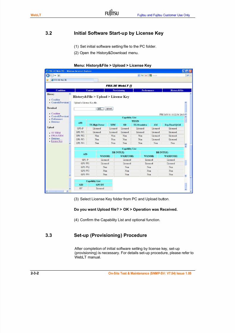
7/24/2019 Frx-3e Test v7.55 Issue1.06 June2014
http://slidepdf.com/reader/full/frx-3e-test-v755-issue106-june2014 52/214
3.2 Initial Software Start-up by License Key
(1) Set initial software setting file to the PC folder.
(2) Open the History&Download menu.
Menu: History&File > Upload > License Key
(3) Select License Key folder from PC and Upload button.
Do you want Upload file? > OK > Operation was Received.
(4) Confirm the Capability List and optional function.
3.3 Set-up (Provisioning) Procedure
After completion of initial software setting by license key, set-up
(provisioning) is necessary. For details set-up procedure, please refer toWebLT manual.
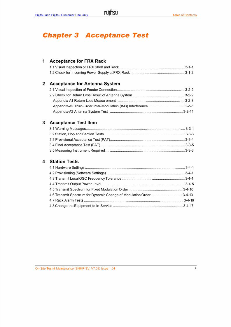
7/24/2019 Frx-3e Test v7.55 Issue1.06 June2014
http://slidepdf.com/reader/full/frx-3e-test-v755-issue106-june2014 53/214
Fujitsu and Fujitsu Customer Use Only Table of Contents
On-Site Test & Maintenance (SNMP-SV: V7.53) Issue 1.04
Chapter 3 Acceptance Test
1 Acceptance for FRX Rack
1.1 Visual Inspection of FRX Shelf and Rack................................................................... 3-1-1
1.2 Check for Incoming Power Supply at FRX Rack ....................................................... 3-1-2
2 Acceptance for Antenna System
2.1 Visual Inspection of Feeder Connection ..................................................................... 3-2-2
2.2 Check for Return Loss Result of Antenna System ................................................... 3-2-2
Appendix-A1 Return Loss Measurement .................................................................... 3-2-3
Appendix-A2 Third-Order Inter-Modulation (IM3) Interference ................................... 3-2-7
Appendix-A3 Antenna System Test .......................................................................... 3-2-11
3 Acceptance Test Item
3.1 Warning Messages ..................................................................................................... 3-3-1
3.2 Station, Hop and Section Tests .................................................................................. 3-3-3
3.3 Provisional Acceptance Test (PAT) ............................................................................ 3-3-4
3.4 Final Acceptance Test (FAT) ...................................................................................... 3-3-5
3.5 Measuring Instrument Required ................................................................................. 3-3-6
4 Station Tests
4.1 Hardware Settings ...................................................................................................... 3-4-1
4.2 Provisioning (Software Settings) ................................................................................ 3-4-1
4.3 Transmit Local OSC Frequency Tolerance ................................................................ 3-4-4
4.4 Transmit Output Power Level ..................................................................................... 3-4-5
4.5 Transmit Spectrum for Fixed Modulation Order ....................................................... 3-4-10
4.6 Transmit Spectrum for Dynamic Change of Modulation Order ................................ 3-4-13
4.7 Rack Alarm Tests ..................................................................................................... 3-4-16
4.8 Change the Equipment to In-Service ....................................................................... 3-4-17

7/24/2019 Frx-3e Test v7.55 Issue1.06 June2014
http://slidepdf.com/reader/full/frx-3e-test-v755-issue106-june2014 54/214
Table of Contents Fujitsu and Fujitsu Customer Use Only
On-Site Test & Maintenance (SNMP-SV: V7.53) Issue 1.04
5 Hop Tests
5.1 Change the Equipment to Maintenance State ............................................................ 3-5-25.2 Receive Signal Level .................................................................................................. 3-5-3
5.3 Delay Equalizer Select................................................................................................ 3-5-6
5.4 Auto IF-IF Response Adjustment ............................................................................... 3-5-7
5.5 Auto SD DADE Adjustment (SD Installation Only) ..................................................... 3-5-8
5.6 Auto XPIC DADE Adjustment (CCDP Operation Only) ............................................. 3-5-9
5.7 Auto RPS DADE Adjustment .................................................................................... 3-5-10
5.8 Radio Protection Switch (RPS) Test ........................................................................ 3-5-11
5.9 Dynamic Change of Modulation Order test .............................................................. 3-5-14
5.10 Stability Test of STM-1 Signal ................................................................................ 3-5-175.11 Gigabit Ethernet Transmission test ........................................................................ 3-5-20
5.12 Change Equipment to In-Service State .................................................................. 3-5-22
6 Section Tests
6.1 RUC Transmission Test ............................................................................................ 3-6-1
6.2 Order Wire (OW) Calling Test .................................................................................... 3-6-2
6.3 Stability Test of Wayside Signal ................................................................................. 3-6-3
6.4 Stability Test of STM-1 Signal .................................................................................... 3-6-5
6.5 Gigabit Ethernet Transmission Test ........................................................................... 3-6-7
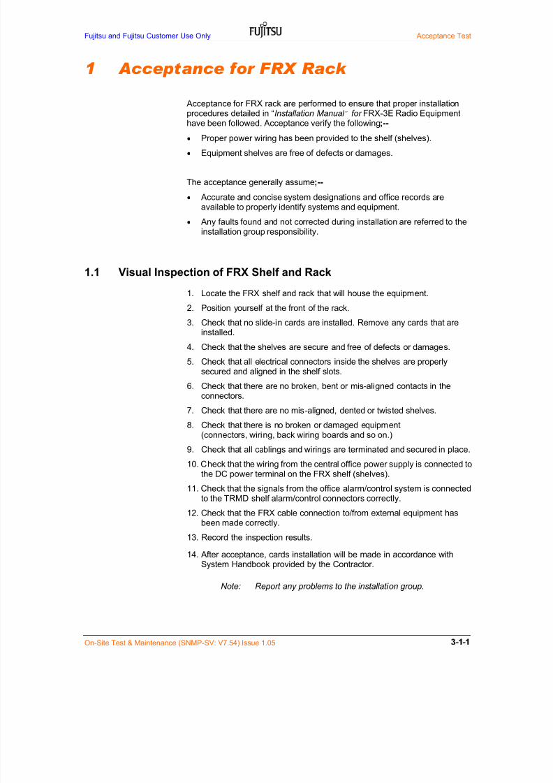
7/24/2019 Frx-3e Test v7.55 Issue1.06 June2014
http://slidepdf.com/reader/full/frx-3e-test-v755-issue106-june2014 55/214
Fujitsu and Fujitsu Customer Use Only Acceptance Test
On-Site Test & Maintenance (SNMP-SV: V7.54) Issue 1.05
1 Acceptance for FRX Rack
Acceptance for FRX rack are performed to ensure that proper installationprocedures detailed in “Installation Manual ” for FRX-3E Radio Equipmenthave been followed. Acceptance verify the following;--
Proper power wiring has been provided to the shelf (shelves).
Equipment shelves are free of defects or damages.
The acceptance generally assume;--
Accurate and concise system designations and office records areavailable to properly identify systems and equipment.
Any faults found and not corrected during installation are referred to theinstallation group responsibility.
1.1 Visual Inspection of FRX Shelf and Rack
1. Locate the FRX shelf and rack that will house the equipment.
2. Position yourself at the front of the rack.
3. Check that no slide-in cards are installed. Remove any cards that areinstalled.
4. Check that the shelves are secure and free of defects or damages.
5. Check that all electrical connectors inside the shelves are properlysecured and aligned in the shelf slots.
6. Check that there are no broken, bent or mis-aligned contacts in theconnectors.
7. Check that there are no mis-aligned, dented or twisted shelves.
8. Check that there is no broken or damaged equipment(connectors, wiring, back wiring boards and so on.)
9. Check that all cablings and wirings are terminated and secured in place.
10. Check that the wiring from the central office power supply is connected to
the DC power terminal on the FRX shelf (shelves).11. Check that the signals from the office alarm/control system is connected
to the TRMD shelf alarm/control connectors correctly.
12. Check that the FRX cable connection to/from external equipment hasbeen made correctly.
13. Record the inspection results.
14. After acceptance, cards installation will be made in accordance withSystem Handbook provided by the Contractor.
Note: Report any problems to the installation group.

7/24/2019 Frx-3e Test v7.55 Issue1.06 June2014
http://slidepdf.com/reader/full/frx-3e-test-v755-issue106-june2014 56/214
Acceptance Test Fujitsu and Fujitsu Customer Use Only
On-Site Test & Maintenence (SNMP-SV: V7.54) Issue 1.05
1.2 Check for Incoming Power Supply to the FRX Shelf
This procedure lists the steps required to check the incoming power supply tothe FRX-3E Basic and Ext-BB shelves. Before beginning this procedure, turnon the main power supply of station power supply system.
1.2.1 Test Equipment Required
Digital Multi-Meter (DMM) or equivalent
1.2.2 Procedure
1. Confirm that the voltage on the Power Supply terminal on commonconnection area is –48 V nominal (Note-1).
2. Turn ON the circuit power breaker outside FRX.
Note-1: FRX-3E specification of input DC primary power is within –40.5 V to –57 V at interface “ A”
including all of variation factors such as station DC power variation, DC power cable loss and so on.
Circuit Breaker (CB)
Rating: DC57V/37A
SD1 3 5 9 7 5 3 1
SDP 2 4 8 6 4 2 P
RX 1 3 5 9 7 5 3 1
RXP 2 4 8 6 4 2 P
TX1 3 5 9 7 5 3 1
TXP 2 4 8 6 4 2 P
L6G, 5+1 11G, 9+1
TERMExt-BB shelf
BRSW
BRSW
BRSW
BRSW
BBINTF(P)
BBINTF(W1)
Basic shelf
ETSI Rack (2,200 mm)
BBINTF(W2)
BBINTF(W1)
BBINTF(W3)
BRSW
BBINTF(W7)
BBINTF(W6)
BBINTF(W5)
BBINTF(P)
BBINTF(W4)
BBINTF(W5)
BBINTF(W9)
BBINTF(W8)
BBINTF(W4)
BBINTF(W2)
BBINTF(W3)
BRSW
BRSW
BRSW
BRSW
BRSW
BRSW
BRSW
BRSW
BRSW
BRSW
BRSW
TERM
BBEXTADPT
BBEXTADPT
GESW
GESW
BBINTF(W1)
BBINTF(P)
BBINTF(W7)
BBINTF(W6)
BBINTF(W5)
SV
AUX
INTF
AUX
INTF
BBINTF(W4)
BBINTF(W3)
BBINTF(W2)
BBINTF(W2)
BBINTF(W3)
BBINTF(W4)
BBINTF(W5)
BBINTF(W9)
BBINTF(W8)
BBINTF(P)
BBINTF(W1)
TRMD(W1)
TRMD(P)
TRMD(W7)
TRMD(W6)
TRMD(W5)
TRMD(W4)
TRMD(W3)
TRMD(W2)
VENTV EN T V EN T V EN T V EN T
TRMD(W2)
TRMD(W3)
TRMD(W4)
TRMD(W5)
TRMD(W9)
TRADPT
TRMD(P)
TRMD(W1)
V EN T V EN T V EN T
TRMD(W8)
Antenna Port (Max. 8)
BEF (x4 m ax.) BEF (x4 m ax.)
TRADPT
TRADPT
TRADPT
TRADPT
TRADPT
TRADPT
TRADPT

7/24/2019 Frx-3e Test v7.55 Issue1.06 June2014
http://slidepdf.com/reader/full/frx-3e-test-v755-issue106-june2014 57/214
Fujitsu and Fujitsu Customer Use Only Acceptance Test
On-Site Test & Maintenance (SNMP-SV: V7.54) issue 1.05 3-2-1
2 Acceptance for Antenna System
Acceptance for antenna system are performed to ensure that properinstallation procedures detailed in the antenna system installation manual
provided by the Contractor have been followed. Acceptance verify thefollowing;--
Proper waveguide flange installation has been provided.
Proper waveguide connection between feeder and antenna has beenprovided.
Proper waveguide connection between feeder and indoor waveguide hasbeen provided.
Proper waveguide connection between DUP/ADPT and indoor waveguidehas been provided.
Waveguide feeder is free of defects or damages.
Waveguide feeder is free of bend beyond permissible limit
Proper return loss test result of antenna system has been provided withgood test results
The acceptance generally assume;--
Accurate and concise system designations and office records areavailable to properly identify systems.
Any faults found and not corrected during installation are referred to theinstallation group responsibility.
The test equipment for return loss of antenna system required is available,properly tested and working correctly.

7/24/2019 Frx-3e Test v7.55 Issue1.06 June2014
http://slidepdf.com/reader/full/frx-3e-test-v755-issue106-june2014 58/214
Acceptance Test Fujitsu and Fujitsu Customer Use Only
3-2-2 On-Site Test & Maintenance (SNMP-SV: V7.54) issue 1.05
2.1 Visual Inspection of Feeder Connection
Proper connection between DUP/ADPT and indoor waveguide has beenprovided.
The acceptance generally assume;--
Do not connect feeder with the equipment until all the twists in the feeder havebeen corrected. See Figure 2.1. Twisting connection may damage waveguideand induce the IM3 distortion.
A person experienced in waveguide connections should carry out theinstallation of the feeder to the equipment.
Figure 2.1 Twisting Wave guides and volt clearance
When the antenna feeders are connected to the radio equipment, payattention not to add a forced twisting torque to the radio equipment ports.
And maximum M4 size volt clearance from the waveguide flange is 12.5 mm.
2.2 Check for Return Loss Result of Antenna System
Proper return loss results has been provided
The acceptance generally assume;--
Proper return loss measurement has been provided.
More than 24 dB (FUJITSU recommends) for all allocated RF band hasbeen provided (5925 to 6425 MHz for L6 GHz band, for example).
Smooth return loss results without spikes and so on has been provided
Anomalies along antenna system may induce the IM3 distortion andinterfere to the receiver RF channels.
Regarding return loss measurement and IM3 interference, please see Appendix-A and B
Equipment Side
max. 12.5
M4 fixing volt
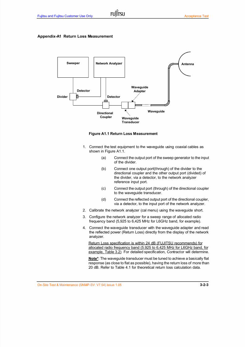
7/24/2019 Frx-3e Test v7.55 Issue1.06 June2014
http://slidepdf.com/reader/full/frx-3e-test-v755-issue106-june2014 59/214
Fujitsu and Fujitsu Customer Use Only Acceptance Test
On-Site Test & Maintenance (SNMP-SV: V7.54) issue 1.05 3-2-3
Appendix-A1 Return Loss Measurement
Figure A1.1 Return Loss Measurement
1. Connect the test equipment to the waveguide using coaxial cables asshown in Figure A1.1.
(a) Connect the output port of the sweep generator to the inputof the divider.
(b) Connect one output port(through) of the divider to thedirectional coupler and the other output port (divided) of
the divider, via a detector, to the network analyzerreference input port.
(c) Connect the output port (through) of the directional couplerto the waveguide transducer.
(d) Connect the reflected output port of the directional coupler,via a detector, to the input port of the network analyzer.
2. Calibrate the network analyzer (cal menu) using the waveguide short.3. Configure the network analyzer for a sweep range of allocated radio
frequency band (5,925 to 6,425 MHz for L6GHz band, for example).
4. Connect the waveguide transducer with the waveguide adapter and readthe reflected power (Return Loss) directly from the display of the networkanalyzer.
Return Loss specification is within 24 dB (FUJITSU recommends) forallocated radio frequency band (5.925 to 6,425 MHz for L6GHz band, forexample, Table 3.2) For detailed specification, Contractor will determine.
Note*: The waveguide transducer must be tuned to achieve a basically flat
response (as close to flat as possible), having the return loss of more than20 dB. Refer to Table 4.1 for theoretical return loss calculation data.
Sweeper
Waveguide
Adapter
Directional
Coupler
Network Analyzer
Waveguide
Transducer
Waveguide
Detector
Detector
Divider
Antenna

7/24/2019 Frx-3e Test v7.55 Issue1.06 June2014
http://slidepdf.com/reader/full/frx-3e-test-v755-issue106-june2014 60/214
Acceptance Test Fujitsu and Fujitsu Customer Use Only
3-2-4 On-Site Test & Maintenance (SNMP-SV: V7.54) issue 1.05
5. In case that Return Loss is out of specification and/or there are spikes andbeard-like distortion within curve, it is necessary to confirm and repair thefeeder flaring installation, feeder dents or something.
NOTE :When sweeping waveguide on the drum, a sliding load must beinserted into the open end of the waveguide to form a temporary termination
(simulation of the antenna).
Table A1.1 Theoretical Return Loss Calculation Data
Return Loss(dB)Reflection
Coefficient (%)VSWR
14.0 19.95 1.50
15.0 17.78 1.43
16.0 15.85 1.3817.0 14.13 1.33
18.0 12.59 1.29
19.0 11.22 1.25
20.0 10.00 1.222
21.0 8.93 1.196
22.0 7.943 1.173
23.0 7.079 1.152
24.0 6.310 1.135
25.0 5.563 1.119
26.0 5.012 1.106
27.0 4.467 1.094
28.0 3.981 1.083
29.0 3.548 1.074
30.0 3.162 1.065
35.0 1.778 1.036
40.0 1.000 1.020
Conversion Formulas
Return Loss: RL 20log()
Reflection Coefficient: (VSWR 1) (VSWR 1)
Voltage Standing Wave Ratio: ................. VSWR (1) (1)
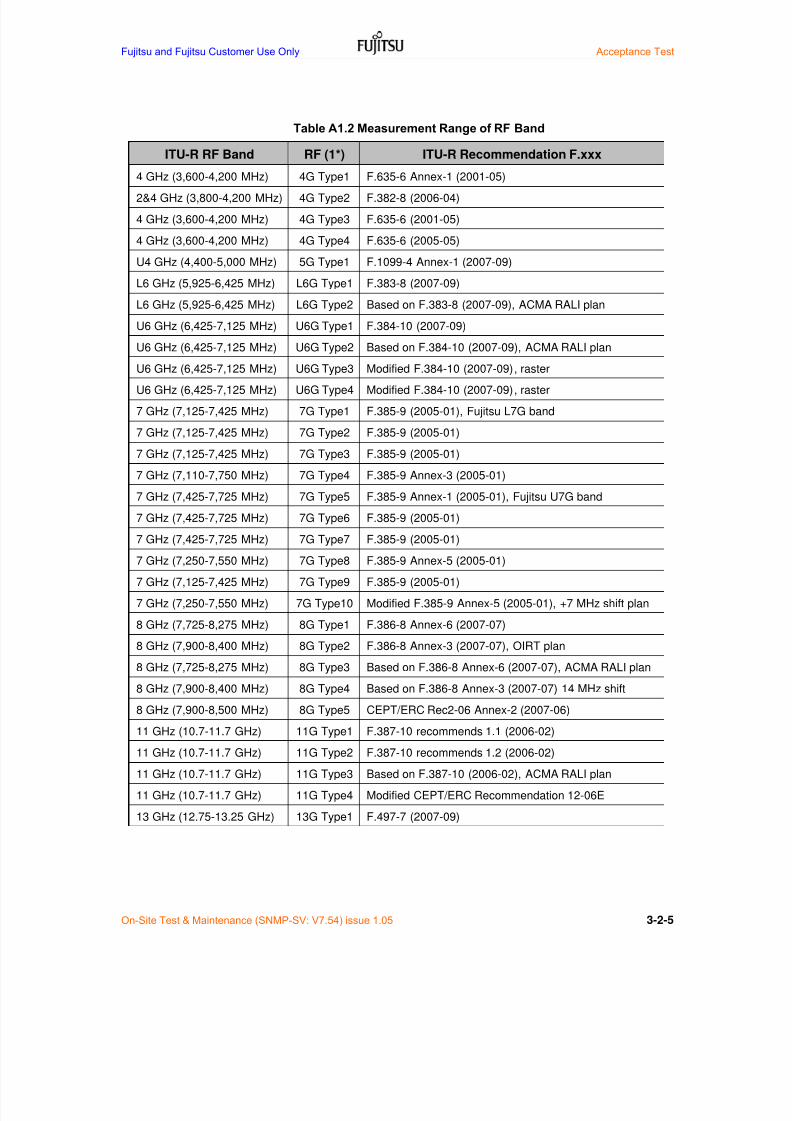
7/24/2019 Frx-3e Test v7.55 Issue1.06 June2014
http://slidepdf.com/reader/full/frx-3e-test-v755-issue106-june2014 61/214
Fujitsu and Fujitsu Customer Use Only Acceptance Test
On-Site Test & Maintenance (SNMP-SV: V7.54) issue 1.05 3-2-5
Table A1.2 Measurement Range of RF Band
ITU-R RF Band RF (1*) ITU-R Recommendation F.xxx
4 GHz (3,600-4,200 MHz) 4G Type1 F.635-6 Annex-1 (2001-05)
2&4 GHz (3,800-4,200 MHz) 4G Type2 F.382-8 (2006-04)
4 GHz (3,600-4,200 MHz) 4G Type3 F.635-6 (2001-05)
4 GHz (3,600-4,200 MHz) 4G Type4 F.635-6 (2005-05)
U4 GHz (4,400-5,000 MHz) 5G Type1 F.1099-4 Annex-1 (2007-09)
L6 GHz (5,925-6,425 MHz) L6G Type1 F.383-8 (2007-09)
L6 GHz (5,925-6,425 MHz) L6G Type2 Based on F.383-8 (2007-09), ACMA RALI plan
U6 GHz (6,425-7,125 MHz) U6G Type1 F.384-10 (2007-09)
U6 GHz (6,425-7,125 MHz) U6G Type2 Based on F.384-10 (2007-09), ACMA RALI plan
U6 GHz (6,425-7,125 MHz) U6G Type3 Modified F.384-10 (2007-09), raster
U6 GHz (6,425-7,125 MHz) U6G Type4 Modified F.384-10 (2007-09), raster
7 GHz (7,125-7,425 MHz) 7G Type1 F.385-9 (2005-01), Fujitsu L7G band
7 GHz (7,125-7,425 MHz) 7G Type2 F.385-9 (2005-01)
7 GHz (7,125-7,425 MHz) 7G Type3 F.385-9 (2005-01)
7 GHz (7,110-7,750 MHz) 7G Type4 F.385-9 Annex-3 (2005-01)
7 GHz (7,425-7,725 MHz) 7G Type5 F.385-9 Annex-1 (2005-01), Fujitsu U7G band
7 GHz (7,425-7,725 MHz) 7G Type6 F.385-9 (2005-01)
7 GHz (7,425-7,725 MHz) 7G Type7 F.385-9 (2005-01)
7 GHz (7,250-7,550 MHz) 7G Type8 F.385-9 Annex-5 (2005-01)
7 GHz (7,125-7,425 MHz) 7G Type9 F.385-9 (2005-01)
7 GHz (7,250-7,550 MHz) 7G Type10 Modified F.385-9 Annex-5 (2005-01), +7 MHz shift plan
8 GHz (7,725-8,275 MHz) 8G Type1 F.386-8 Annex-6 (2007-07)
8 GHz (7,900-8,400 MHz) 8G Type2 F.386-8 Annex-3 (2007-07), OIRT plan
8 GHz (7,725-8,275 MHz) 8G Type3 Based on F.386-8 Annex-6 (2007-07), ACMA RALI plan
8 GHz (7,900-8,400 MHz) 8G Type4 Based on F.386-8 Annex-3 (2007-07) 14 MHz shift
8 GHz (7,900-8,500 MHz) 8G Type5 CEPT/ERC Rec2-06 Annex-2 (2007-06)
11 GHz (10.7-11.7 GHz) 11G Type1 F.387-10 recommends 1.1 (2006-02)
11 GHz (10.7-11.7 GHz) 11G Type2 F.387-10 recommends 1.2 (2006-02)
11 GHz (10.7-11.7 GHz) 11G Type3 Based on F.387-10 (2006-02), ACMA RALI plan
11 GHz (10.7-11.7 GHz) 11G Type4 Modified CEPT/ERC Recommendation 12-06E
13 GHz (12.75-13.25 GHz) 13G Type1 F.497-7 (2007-09)

7/24/2019 Frx-3e Test v7.55 Issue1.06 June2014
http://slidepdf.com/reader/full/frx-3e-test-v755-issue106-june2014 62/214
Acceptance Test Fujitsu and Fujitsu Customer Use Only
3-2-6 On-Site Test & Maintenance (SNMP-SV: V7.54) issue 1.05
Table A1-3 RF Flange Specification
RF band Flange Mating Frequency Range(MHz)IEC standard
4G Type1 UDR 40 3,600 - 4,200
4G Type2 UDR 40 3,800 - 4,200
4G Type3 UDR 40 3,600 – 4,200
4G Type4 UDR 40 3,600 – 4,200
5G Type1 UDR 48 4,400 – 5,000
L6G Type1/2 UDR 70 5,925 – 6,175
U6G Type1/2/3/4 UDR 70 6,425 –
7,125
7G Type1/2/3/9 UDR 70/84* 7,125 – 7,425
7G Type4 UDR 70/84* 7,110 – 7,750
7G Type5/6/7 UDR 70/84* 7,425 – 7,725
7G Type8/10 UDR 70/84* 7,250 – 7,550
8G Type1/3 UDR 84 7,725 – 8,275
8G Type2/4 UDR 84 7,900 – 8,400
8G Type5 UDR 84 7,900 – 8,500
11G Type1/2/3 UDR 100 10,700 –
11,700
11G Type4 UDR 100 10,700 – 11,700
13G Type1 UDR 120 12,750 – 13,250
Note*: Both specification is available and customer will select.
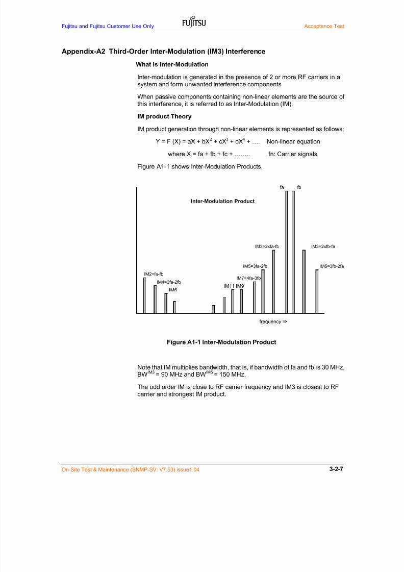
7/24/2019 Frx-3e Test v7.55 Issue1.06 June2014
http://slidepdf.com/reader/full/frx-3e-test-v755-issue106-june2014 63/214
Fujitsu and Fujitsu Customer Use Only Acceptance Test
On-Site Test & Maintenance (SNMP-SV: V7.53) issue1.04
Appendix-A2 Third-Order Inter-Modulation (IM3) Interference
What is Inter-Modulation
Inter-modulation is generated in the presence of 2 or more RF carriers in a
system and form unwanted interference components
When passive components containing non-linear elements are the source ofthis interference, it is referred to as Inter-Modulation (IM).
IM product Theory
IM product generation through non-linear elements is represented as follows;
Y = F (X) = aX + bX2 + cX
3 + dX
4 + …. Non-linear equation
where X = fa + fb + fc + …….. fn: Carrier signals
Figure A1-1 shows Inter-Modulation Products.
Figure A1-1 Inter-Modulation Product
Note that IM multiplies bandwidth, that is, if bandwidth of fa and fb is 30 MHz,BW
IM3 = 90 MHz and BW
IM5 = 150 MHz.
The odd order IM is close to RF carrier frequency and IM3 is closest to RFcarrier and strongest IM product.
IM11
IM7=4fa-3fb
frequency⇒
IM2=fa-fb
IM4=2fa-2fb
IM5=3fb-2faIM5=3fa-2fb
IM6IM9
fa fb
IM3=2xfb-faIM3=2xfa-fb
Inter-Modulation Product

7/24/2019 Frx-3e Test v7.55 Issue1.06 June2014
http://slidepdf.com/reader/full/frx-3e-test-v755-issue106-june2014 64/214
Acceptance Test Fujitsu and Fujitsu Customer Use Only
On-Site Test & Maintenance (SNMP-SV: V7.53) issue 1.04
Cause of Inter-Modulation in Microwave Radio System
In the microwave radio system, cause of non-linear elements in theantenna system in the presence of more than 2 RF signals is;
- Surface oxides (feeder)
- Loose metal to metal contacts (DUP/ADPT-WG connection)
- Use of ferromagnetic materials (DUP/ADPT)
- Contaminations, eg. solder splatters (Inside feeder, WG connector)
- Insufficient thickness of plated metal, causing RF heating (feeder bend)
- Too much or too little torque at connectors (DUP/ADPT-WG connection)
IM3 Interference to the Receiver ChannelsIn microwave radio system, inter-modulation (IM) generated in theantenna system is interfered to the receiver RF channels under conditions;
- Common antenna system for transmitters and main receivers
- High transmit output power for more than 2 RF channels
- High sensitivity receiver (Threshold RSL less than –70 dBm)
- IM3 product is generated in antenna system and interfered to receiver RFchannels as feeder echo as shown in Figure A2-1.
Figure A2-2 shows the IM3 interference example of U6GHz band. In thiscase transmit RF channels are lower half band and receiver RF channelsare upper half band.
Appendix-A3 shows the antenna system test to confirm IM3 occurrence.

7/24/2019 Frx-3e Test v7.55 Issue1.06 June2014
http://slidepdf.com/reader/full/frx-3e-test-v755-issue106-june2014 65/214
Fujitsu and Fujitsu Customer Use Only Acceptance Test
On-Site Test & Maintenance (SNMP-SV: V7.53) issue1.04
Transmitter, +32 dBm each F1 to F8 Receiver, RSL threshold –70 dBm for 128QAM
Y = F (X) = aX + bX2 + cX
3 + dX
4 + ……
X = F1 + F2 + F3 + F4 + F5 + F6 + F7 + F8
Figure A2-1 N-Order Inter-Modulation (IMn) Interference Mechanism
(IM3 is closest to RF CH carrier and has strongest IM result)
CIR
BPBP
CIR
BPBP
CH2CH4 CH3 CH1
Transmit side
Transmit side
CIR
C/WV(H)
Main
Antenna
CIRCIR
BPBP
BEF
BPBP
CH2CH4 CH3 CH1
Main Receive side
CIR CIR
BPBP
BEF
BPBP
CH5CH7CH8 CH6
CIR
BPBP
CIR
BPBP
CH8’ CH7 CH5
Main Receive
side
CH6’
DUP
Non-linearity elements⇒ IM3 generation
Non-linear elements
Y = F (x)
IM3 interference to RX signal
IM3 interference
route
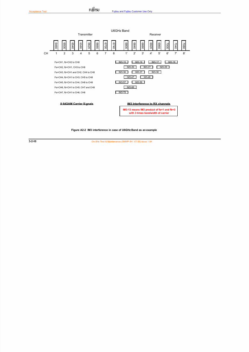
7/24/2019 Frx-3e Test v7.55 Issue1.06 June2014
http://slidepdf.com/reader/full/frx-3e-test-v755-issue106-june2014 66/214
Acceptance Test Fujitsu and Fujitsu Customer Use Only
On-Site Test & Maintenance (SNMP-SV: V7.53) issue 1.04
Figure A2-2 IM3 interference in case of U6GHz Band as an example
Fa=CH1, fb=CH2 to CH8
Fa=CH2, fb=CH1, CH3 to CH8
Fa=CH3, fb=CH1 and CH2, CH4 to CH8
Fa=CH4, fb=CH1 to CH3, CH5 to CH8
Fa=CH5, fb=CH1 to CH4, CH6 to CH8
Fa=CH6, fb=CH1 to CH5, CH7 and CH8
Fa=CH7, fb=CH1 to CH6, CH8
IM3-68
IM3-78
8 64QAM Carrier Signals IM3 Interference to RX channels
IM3-13 means IM3 product of fa=1 and fb=3
with 3 times bandwidth of carrier
IM3-47 IM3-48
IM3-57 IM3-58
IM3-28IM3-27IM3-26
IM3-37 IM3-38IM3-36
CH
U6GHz Band
IM3-18IM3-17IM3-16IM3-15
5' 6' 7'
Transmitter
8'1' 2' 3' 4'
Receiver
1 2 3 4 5 6 7 8
6 9 6 0
7 0 0 0
7 0 4 0
7 0 8 0
6 8 0 0
6 8 4 0
6 8 8 0
6 9 2 0
6 6 2 0
6 6 6 0
6 7 0 0
6 7 4 0
6 4 6 0
6 5 0 0
6 5 4 0
6 5 8 0
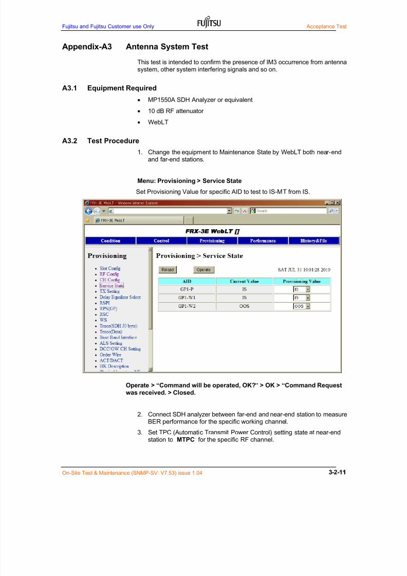
7/24/2019 Frx-3e Test v7.55 Issue1.06 June2014
http://slidepdf.com/reader/full/frx-3e-test-v755-issue106-june2014 67/214
Fujitsu and Fujitsu Customer use Only Acceptance Test
On-Site Test & Maintenance (SNMP-SV: V7.53) issue 1.04
Appendix-A3 Antenna System Test
This test is intended to confirm the presence of IM3 occurrence from antennasystem, other system interfering signals and so on.
A3.1 Equipment Required
MP1550A SDH Analyzer or equivalent
10 dB RF attenuator
WebLT
A3.2 Test Procedure
1. Change the equipment to Maintenance State by WebLT both near-endand far-end stations.
Menu: Provisioning > Service State
Set Provisioning Value for specific AID to test to IS-MT from IS.
Operate > “Command will be operated, OK?” > OK > “Command Requestwas received. > Closed.
2. Connect SDH analyzer between far-end and near-end station to measureBER performance for the specific working channel.
3. Set TPC (Automatic Transmit Power Control) setting state at near-end
station to “MTPC” for the specific RF channel.

7/24/2019 Frx-3e Test v7.55 Issue1.06 June2014
http://slidepdf.com/reader/full/frx-3e-test-v755-issue106-june2014 68/214
Acceptance Test Fujitsu and Fujitsu Customer Use Only
3-2- On-Site Test & Maintenance (SNMP-SV: V7.53) issue 1.04
4. Set MTPC setting state at far-end station to “-20 dB” for the specific RFchannel and other RF channels are power OFF at far-end station.
Menu: Provisioning > TX Setting
Operate > “Command will be operated, OK?” > OK > “CommandRequest was received. > Closed.
5. Remove TX OUT connection between the RF branching network (BRU)and MSTU ADPT (TX) at far-end station for the specific RF channel.
6. Connect RF attenuator to the TR ADPT TX OUT (at Point B’).(RSL is set to approx. 10 dB higher than threshold RSL at BER=10(-6))
7. Measure BER performance and confirm error free for fifteen (15) minutes.
8. TPC setting state at far-end station to “MTPC” for the specific RF channel.
9. Repeat item 2 through item 8 for all RF channels.
10. TPC setting state both far-end and near-end station for all RF channels.
11. Change the equipment to “In-Service” State by WebLT both near-endand far-end station.
Note-1: Report any problems to the installation group to check the antenna system.Note-2: Schematic block diagram of Antenna system is shown in Figure A3.1.
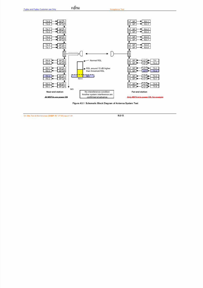
7/24/2019 Frx-3e Test v7.55 Issue1.06 June2014
http://slidepdf.com/reader/full/frx-3e-test-v755-issue106-june2014 69/214
Fujitsu and Fujitsu Customer use Only Acceptance Test
On-Site Test & Maintenance (SNMP-SV: V7.53) issue1.04
IM3
Normal RSL
RSL around 15 dB higher
than threshold RSL
TX-5
TX-7
ATT
ATT C I R
BP
BP
TX-6
TX-8
TX1
TX-3
TX-2
TX-4
Near-end station Far-end station
IM3
All MSTUs are power ON Only MSTU-4 is power ON, for example
No intereference condition
Another system interference are
confirmed at advance
RX-4
RX-2
RX-3
RX-1
RX-8
RX-6
RX-7
RX-5
RX-5'
RX-7'
RX-6'
RX-8'
RX-1'
RX-3'
RX-2'
RX-4'
ATT
ATT
ATT
ATT
ATT
ATTBP
BP
TX-8'
TX-6'
TX-7'
TX-5'
TX-4'
TX-2'
TX-3'
TX-1' C I R
BP
BP
C I R
BP
BP
C I R
BP
BP
C I R
D U P
BP
BP C I R
C I R
BP
BP
C I R
BP
BP
BP C
I R
BP
D U P
BP C I R
BP
BP C
I R BP
BP C
I R BP
BP C
I R BP
RX-4
C I R
BP
BP
BP C
I R BP
BP C
I R BP

7/24/2019 Frx-3e Test v7.55 Issue1.06 June2014
http://slidepdf.com/reader/full/frx-3e-test-v755-issue106-june2014 70/214
Acceptance Test Fujitsu and Fujitsu Customer Use Only
5-2- On-Site Test & Maintenance (SNMP-SV: V7.53) issue 1.04

7/24/2019 Frx-3e Test v7.55 Issue1.06 June2014
http://slidepdf.com/reader/full/frx-3e-test-v755-issue106-june2014 71/214
Fujitsu and Fujitsu Customer Use Only Acceptance Test Item
On-Site test & Maintenance (SNMP-SV: V7.53) Issue 1.04 3-3-1
3 Acceptance Test ItemThis section outlines the acceptance tests required to commission theFRX-3E Radio System.
3.1 Warning Messages
The following safety precautions must be observed when installing, using, ormaintaining electronic equipment. These precautions ensure the safety of allpersonnel and the protection of equipment.
3.1.1 Laser Warning
Figure 3.1 shows the warning labels that are attached to all laser emitting andreceiving units:
CAUTION
Invisible laser radiation from
connectors when uncoupled.
AVOID DIRECT EXPOSURE TO
BEAM.
Figure 3.1 Laser Warning Labels
3.1.2 Inserting Slide-in Cards
CAUTION
During installation or replacement, seat all slide-in cards with aslow but firm motion. Do not push them quickly into a slot.
Many slide-in cards have longer power connector pins to minimize
power surges during installation. Insert the slide-in cards slowly toavoid damage.
CAUTION
(1) NEVER look into the end of an optical cable or fibre pigtail.
(2) PERMANENT EYE DAMAGE or BLINDNESS can occur
if laser radiation is present.
(3) NEVER handle exposed fibre with bare hands or permit
contact with the body. Fibre fragments into skin are difficultto detect and remove.

7/24/2019 Frx-3e Test v7.55 Issue1.06 June2014
http://slidepdf.com/reader/full/frx-3e-test-v755-issue106-june2014 72/214
Acceptance Test Item Fujitsu and Fujitsu Customer Use Only
3-3-2 On-Site Test & Maintenance (SNMP-SV: V7.53) Issue 1.04
3.1.3 Electrostatic Discharge Warning
Figure 3.2 ESD Warning Label
CAUTION
Many slide-in cards can be damaged by electrostatic dischargeduring installation, removal, storage, or shipment. Such cards haveElectrostatic Discharge (ESD) warning labels attached (Figure 3.2)and are required special care in handling and storage. The followingprecautions must be strictly observed:
Always wear a wrist strap connected to the ground terminal whenhandle the slide-in cards. The wrist strap must have a minimumresistance of 250 kohms. Before using the wrist strap, check forcontinuity, shorts and minimum resistance value. Replace the wriststrap if it fails any of these checks.
Hold only the edge of the slide-in cards. Do not touch IC leads or
circuitry on the cards.
Transport or store slide-in cards in the special bags in which thecards were originally shipped. Always fold the open end of the bagover and secure with tape.
Return cards to Fujitsu Wireless Systems representatives in specialbags and original shipping containers.
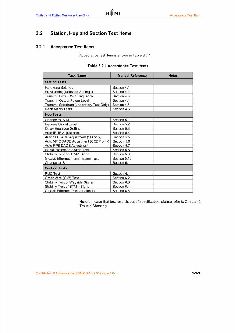
7/24/2019 Frx-3e Test v7.55 Issue1.06 June2014
http://slidepdf.com/reader/full/frx-3e-test-v755-issue106-june2014 73/214
Fujitsu and Fujitsu Customer Use Only Acceptance Test Item
On-Site test & Maintenance (SNMP-SV: V7.53) Issue 1.04 3-3-3
3.2 Station, Hop and Section Test Items
3.2.1 Acceptance Test Items
Acceptance test item is shown in Table 3.2.1
Table 3.2.1 Acceptance Test Items
Task Name Manual Reference Notes
Station Tests
Hardware Settings Section 4.1
Provisioning(Software Settings) Section 4.2
Transmit Local OSC Frequency Section 4.3
Transmit Output Power Level Section 4.4Transmit Spectrum (Laboratory Test Only) Section 4.5
Rack Alarm Tests Section 4.6
Hop Tests
Change to IS-MT Section 5.1
Receive Signal Level Section 5.2
Delay Equalizer Setting Section 5.3
Auto IF- IF Adjustment Section 5.4
Auto SD DADE Adjustment (SD only) Section 5.5
Auto XPIC DADE Adjustment (CCDP only) Section 5.6
Auto RPS DADE Adjustment Section 5.7
Radio Protection Switch Test Section 5.8
Stability Test of STM-1 Signal Section 5.9
Gigabit Ethernet Transmission Test Section 5.10
Change to IS Section 5.11
Section Tests
RUC Test Section 6.1
Order Wire (OW) Test Section 6.2
Stability Test of Wayside Signal Section 6.3
Stability Test of STM-1 Signal Section 6.4
Gigabit Ethernet Transmission test Section 6.5
Note*: In case that test result is out of specification, please refer to Chapter 6Trouble Shooting.

7/24/2019 Frx-3e Test v7.55 Issue1.06 June2014
http://slidepdf.com/reader/full/frx-3e-test-v755-issue106-june2014 74/214
Acceptance Test Item Fujitsu and Fujitsu Customer Use Only
3-3-4 On-Site Test & Maintenance (SNMP-SV: V7.53) Issue 1.04
3.2.2 Scope of Station, Hop and Section Tests
Acceptance tests are summarized by three (3) parts;
(1) Station Test(2) Hop Test
(3) Section Test (Terminal-to-Terminal Test)
Figure 3.1 shows the scope of on-site acceptance test.
Figure 2.3 Scope of On-site Acceptance Tests
Station A and U: Terminal station with STM-1 add/drop facility
Station B to T: Terminal/Repeater station without STM-1 add/drop facility
3.3 Provisional Acceptance Test (PAT)
Provisional acceptance test (PAT) is the commissioning test carried out at
initial stage after FRX-3E delivery on site as follows;--
Preparation for acceptance test included
Station test items indicated in Table 3.2.1 included
Hop test items indicated in Table 3.2.1 included Section items indicated in Table 3.2.1 included
After provisional acceptance test, test operation period more than threemonths will be made
A B C S T UStation Name
Station Tests
Hop Tests
Section Tests
Radio Route

7/24/2019 Frx-3e Test v7.55 Issue1.06 June2014
http://slidepdf.com/reader/full/frx-3e-test-v755-issue106-june2014 75/214
Fujitsu and Fujitsu Customer Use Only Acceptance Test Item
On-Site test & Maintenance (SNMP-SV: V7.53) Issue 1.04 3-3-5
3.4 Final Acceptance Test (FAT)
Final acceptance test (FAT) is carried out after service operation on site as
follows;--
Limited Station test items indicated in Table 3.2.1 included
Limited Hop test items indicated in Table 3.2.1 included
Limited Section items indicated in Table 3.2.1 included
Final circuit quality should be met with Tender Specification in accordancewith ITU-T M.2101 and ITU-R F.1033.
FUJITSU recommended FAT test item is shown in Table 3.4.
Table 3.4 Recommended Final Acceptance Test Items
Task Name Manual Reference Notes
Station Tests
Transmit Local OSC Frequency Section 3.3
Transmit Output Power Level Section 3.4
Hop Tests
Receive Signal Level Section 4.1
Radio Protection Switch Test Section 4.8
Section Tests
Order Wire (OW) Test Section 5.2
Stability Test of Wayside Signal Section 5.3
Stability Test of STM-1 Signal Section 5.4
Gigabit Ethernet Transmission test Section 5.5

7/24/2019 Frx-3e Test v7.55 Issue1.06 June2014
http://slidepdf.com/reader/full/frx-3e-test-v755-issue106-june2014 76/214
Acceptance Test Item Fujitsu and Fujitsu Customer Use Only
3-3-6 On-Site Test & Maintenance (SNMP-SV: V7.53) Issue 1.04
3.5 Measuring Instrument Required
The typical measuring instrument required to carry out the commissioning
tests are as follows;--
In case of Station & Hop Tests
RF power meter
RF Variable & fixed attenuator (10 W type)
Frequency counter (> 30 MHz)
Multi-meter
PC for WebLT(Local terminal)
In case of Section Tests
RF power meter
RF variable & fixed attenuator (10 W type)
STM-1 transmission analyzer
BER measuring equipment for 64k & 2M)
PC for WebLT(Local terminal)
In case of Laboratory Test
RF power meter
Spectrum analyzer
RF Variable & fixed attenuator (10 W type)
Miscellaneous RF/IF cables and accessories
STM-1 transmission analyzer
Variable optical attenuator with LC Duplex connectors*1
Optical power meter with LC connectors
Optical fiber patch cords with LC connectors
Frequency counter (< 30 MHz)
Multi-meter
PC for WebLT(Local terminal)
7/24/2019 Frx-3e Test v7.55 Issue1.06 June2014
http://slidepdf.com/reader/full/frx-3e-test-v755-issue106-june2014 77/214
Fujitsu and Fujitsu Customer Use Only Acceptance Test
On-Site Test & Maintenance (SNMP-SV: V7.54) issue 1.05 3-4-1
4 Station TestsThis section provides instructions for in-station tests for the FRX-3E radioequipment.
4.1 Hardware Settings
4.1.1 Setting Values
Hardware setting for FRX-3E equipment per station is in accordance with theSYSTEM HANDBOOK provided by the Contractor. Please do not touchthese hardware settings except in unavoidable cases.
Note: Report any problems to the commissioning manager.
4.2 Provisioning (Software Settings)4.2.1 Setting Values
Provisioning setting (Software Setting) for FRX-3E equipment per station isin accordance with the SYSTEM HANDBOOK provided by the Contractor.Please do not change these provisioning settings except in unavoidablecases.
For detailed provisioning item description, please refer to Chapter 4Provisioning a System of Web-Based LT Manual (T101-1759-05).
Note: Report any problems to the commissioning manager.
NOTICE:
Setting values displayed on WebLT screens areinitial setting values in accordance with SystemHandbook provided by the Contractor.
If you accidentally change provisioning settingdata on WebLT screen, FRX-3E radio system maynot function properly in some case.
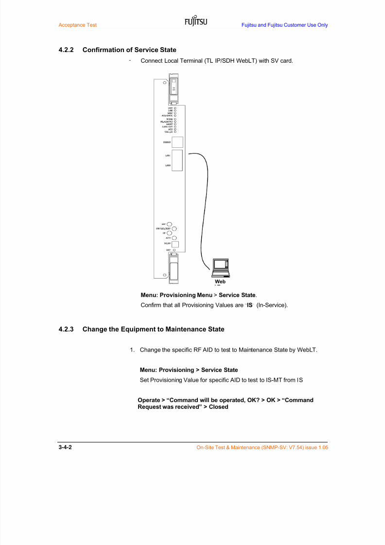
7/24/2019 Frx-3e Test v7.55 Issue1.06 June2014
http://slidepdf.com/reader/full/frx-3e-test-v755-issue106-june2014 78/214
Acceptance Test Fujitsu and Fujitsu Customer Use Only
3-4-2 On-Site Test & Maintenance (SNMP-SV: V7.54) issue 1.05
4.2.2 Confirmation of Service State
- Connect Local Terminal (TL IP/SDH WebLT) with SV card.
Menu: Provisioning Menu > Service State.
Confirm that all Provisioning Values are “IS” (In-Service).
4.2.3 Change the Equipment to Maintenance State
1. Change the specific RF AID to test to Maintenance State by WebLT.
Menu: Provisioning > Service State
Set Provisioning Value for specific AID to test to IS-MT from IS
Operate > “Command will be operated, OK? > OK > “CommandRequest was received” > Closed
Web

7/24/2019 Frx-3e Test v7.55 Issue1.06 June2014
http://slidepdf.com/reader/full/frx-3e-test-v755-issue106-june2014 79/214
Fujitsu and Fujitsu Customer Use Only Acceptance Test
On-Site Test & Maintenance (SNMP-SV: V7.54) issue 1.05 3-4-3
4.3 Transmit Local OSC Frequency Tolerance
This test is to check the TX local oscillator tolerance of TRMD card.
4.3.1 Test Equipment Required
Frequency counter ( < 30 MHz)
4.3.2 Specification
Within 20.0 MHz +/- 200 Hz (10 ppm)measured at LOC F MON connector on TRMD cardNOTICE: Within 19.2 MHz +/- 192 Hz (10 ppm) only for 8G-T1 of TRMD v1
(NOTE: Transmit local OSC frequency tolerance measurement is not directmeasurement of TX LOC RF output, but that of reference clock of TX LOC.)
4.3.3 Test Procedure
1. Set up test circuit as shown in Figure 4.1
2. Record frequency tolerance results.
3. Compare the results and specification value.
Note: Report any problems to the commissioning manager.
Figure 4.1 TX Local Frequency Measurement
FrequencyCounter<30 MHz
SD1 3 5 9 7 5 3 1
SDP 2 4 8 6 4 2 P
RX1 3 5 9 7 5 3 1
RXP 2 4 8 6 4 2 P
TX1 3 5 9 7 5 3 1
TXP 2 4 8 6 4 2 P
Antenna Port (Max. 8)
BEF (x4 max.) BEF (x4 max.)
TRADPT
TRADPT
TRADPT
TRADPT
TRADPT
TRADPT
TRADPT
TRADPT
TRMD(W1)
TRMD(W2)
TRMD(W3)
V EN T VE NT V EN TVENT VENT
TRMD(P)
TRMD(W5)
TRMD(W9)
TRMD(W8)
TRMD(W7)
TRMD(W6)
VE NT VEN T VE NT
TRMD(W5)
TRMD(W4)
TRMD(W3)
TRMD(W2)
TRMD(W1)
TRMD(P)
Basic shelf
TRMD(W4)

7/24/2019 Frx-3e Test v7.55 Issue1.06 June2014
http://slidepdf.com/reader/full/frx-3e-test-v755-issue106-june2014 80/214
Acceptance Test Fujitsu and Fujitsu Customer Use Only
3-4-4 On-Site Test & Maintenance (SNMP-SV: V7.54) issue 1.05
4. 4 Transmit Output Power Level
This test is to check the RF output power of TRMD card.
4. 4.1 Equipment Required WebLT (Local terminal)
TRMD TEST ADPT
4. 4.2 Specifications
In accordance with Table 4.4-1 and Table 4.4-2 below;Measured at TRMD card output port.
Table 4.4-1 Transmit Output Power for STM-1 interface (dBm)
Modulation30 MHz CS 40 MHz CS
ToleranceSTP/with OD HP/with OD STP/with OD HP/with OD
64QAM (4-8G) - - +30/+32 +33/+35
+/-1 dB
64QAM (11G) - - +30/+32 -
128QAM (4-8G) +29/+31 +32/+34 - -
128QAM (11G) +29/+31 - - -
128QAM (13G) +27/+29 - - -
Table 4.4-2a Transmit Output Power for Native IP interface and 30 MHz CS (dBm)Highest
Modulation4 to 8 GHz
STP/with OD4 to 8 GHzHP/with OD
11 GHzSTD/with OD
13 GHzSTD/with OD
Tolerance
QPSK +29/+31 +32/+34 +29/+31 +27/+29
+/-1 dB
8QAM +29/+31 +32/+34 +29/+31 +27/+29
16QAM +29/+31 +32/+34 +29/+31 +27/+2932QAM +29/+31 +32/+34 +29/+31 +27/+29
64QAM +29/+31 +32/+34 +29/+31 +27/+29
128QAM +29/+31 +32/+34 +29/+31 +27/+29
256QAM +26/(*1) +31/(*1) +28/(*1) +26/(*1)
512QAM +25/(*1) +30/(*1) +29/(*1) +27/(*1)
Table 4.4-2b Transmit Output Power for Native IP interface and 40 MHz CS (dBm)Highest
Modulation4 to 8 GHz
STD/with OD4 to 8 GHzHP/with OD
11 GHzSTD/with OD
Tolerance
QPSK +30/+32 +33/+35 +30/+32 -
+/-1 dB
8QAM +30/+32 +33/+35 +30/+32 -
16QAM +30/+32 +33/+35 +30/+32 -32QAM +30/+32 +33/+35 +30/+32 -
64QAM +30/+32 +33/+35 +30/+32 -
128QAM +29/(*1) +32/(*1) +29/(*1) -
256QAM +28/(*1) +31/(*1) +28/(*1) -
512QAM +27/(*1) +30/(*1) +27/(*1) -
STD: Standard power, HP: High power, OD: TX overdrive
Note-1*: TX overdrive function (OD) is not recommended for use.
NOTICE: TX output power adjustment using MTPC function in the Transmitter Parameter isrequired when 256/512QAM for 30 MHz CS and 128/256/512QAM for 40 MHz CS
is applied.

7/24/2019 Frx-3e Test v7.55 Issue1.06 June2014
http://slidepdf.com/reader/full/frx-3e-test-v755-issue106-june2014 81/214
Fujitsu and Fujitsu Customer Use Only Acceptance Test
On-Site Test & Maintenance (SNMP-SV: V7.54) issue 1.05 3-4-5
4.4.3 Test Procedure
Menu: Performance > Others > Analog Monitor
1. Select specific AID to test.
Operate > “Command will be operated, OK? > OK
2. Analog monitor result appears
Note-*1: In case that TX output power by using power meter is needed, refer to Appendix-A.
3. When already calibrated transmit power output (TL) is withinspecification, skip to next test and change the equipment to In-Service(IS) state.
When transmit power output is out of specification
4. Remove the specific CIR OUT cable on TRMD Adaptor (TR ADPT).
5. Connect power meter into the CIR connector on TR ADPT.If the maximum range of the power meter is less than the rated outputpower level of the TX, insert fixed and calibrated attenuator between theTX output and the power meter.
6. Read the power meter indication.
7. If the measured power is out of the rated level, logon NE (NetworkElement) by WebLT.
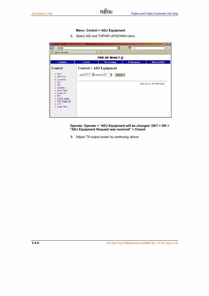
7/24/2019 Frx-3e Test v7.55 Issue1.06 June2014
http://slidepdf.com/reader/full/frx-3e-test-v755-issue106-june2014 82/214
Acceptance Test Fujitsu and Fujitsu Customer Use Only
3-4-6 On-Site Test & Maintenance (SNMP-SV: V7.54) issue 1.05
Menu: Control > ADJ Equipment
8. Select AID and TXPWR UP/DOWN menu.
Operate: Operate > “ADJ Equipment will be changed. OK? > OK >“ADJ Equipment Request was received” > Closed
9. Adjust TX output power by continuing above.
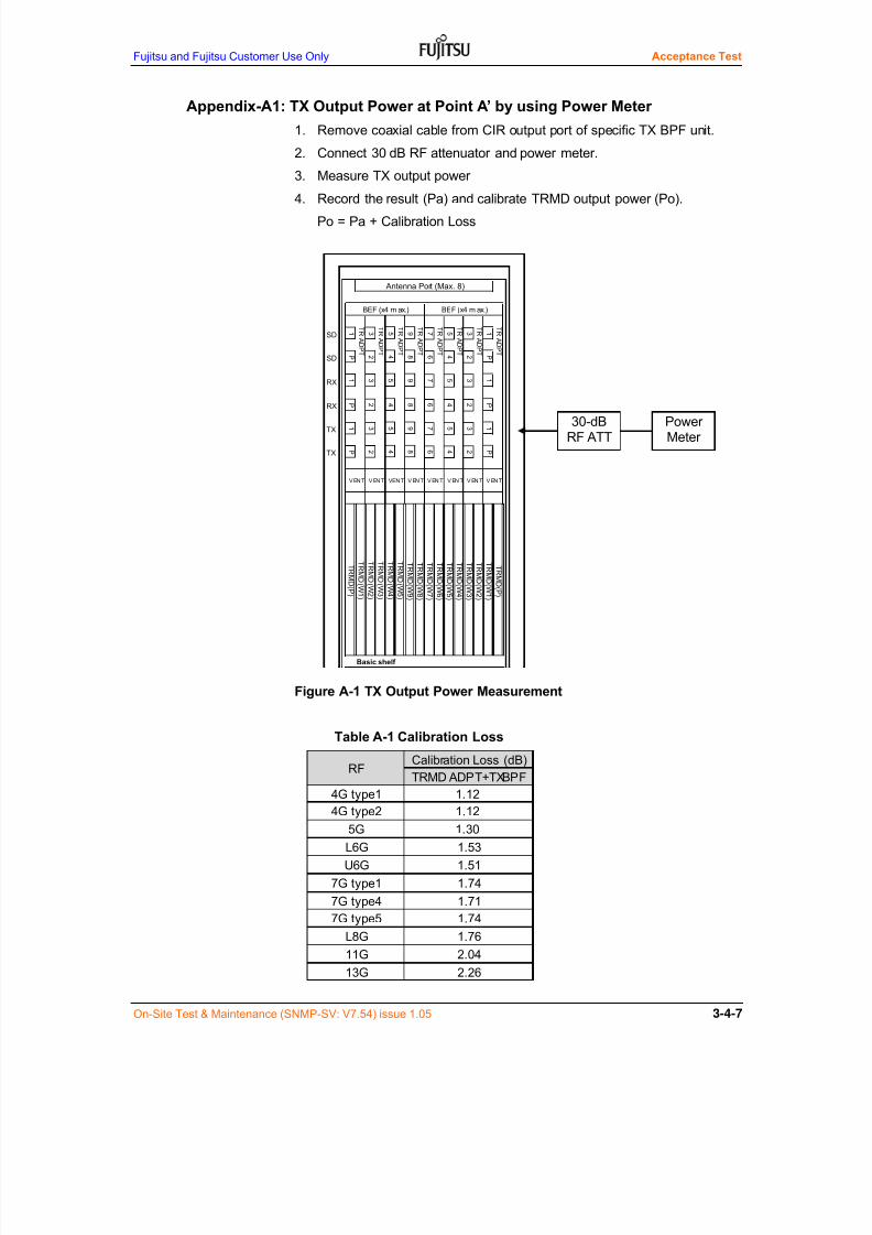
7/24/2019 Frx-3e Test v7.55 Issue1.06 June2014
http://slidepdf.com/reader/full/frx-3e-test-v755-issue106-june2014 83/214
Fujitsu and Fujitsu Customer Use Only Acceptance Test
On-Site Test & Maintenance (SNMP-SV: V7.54) issue 1.05 3-4-7
Appendix-A1: TX Output Power at Point A’ by using Power Meter
1. Remove coaxial cable from CIR output port of specific TX BPF unit.
2. Connect 30 dB RF attenuator and power meter.
3. Measure TX output power
4. Record the result (Pa) and calibrate TRMD output power (Po).
Po = Pa + Calibration Loss
Figure A-1 TX Output Power Measurement
Table A-1 Calibration Loss
30-dBRF ATT
PowerMeter
SD1 3 5 9 7 5 3 1
SDP 2 4 8 6 4 2 P
RX1 3 5 9 7 5 3 1
RXP 2 4 8 6 4 2 P
TX1 3 5 9 7 5 3 1
TXP 2 4 8 6 4 2 P
Antenna Port (Max. 8)
BEF (x4 m ax.) BEF (x4 m ax.)
TRADPT
TRADPT
TRADPT
TRADPT
TRADPT
TRADPT
TRADPT
TRADPT
TRMD(W1)
TRMD(W2)
TRMD(W3)
V EN T V EN T V EN TVENT VENT
TRMD(P)
TRMD(W5)
TRMD(W9)
TRMD(W8)
TRMD(W7)
TRMD(W6)
VEN T V EN T V EN T
TRMD(W5)
TRMD(W4)
TRMD(W3)
TRMD(W2)
TRMD(W1)
TRMD(P)
Basic shelf
TRMD(W4)
13G 2.26
7G type5 1.74
L8G 1.7611G 2.04
U6G 1.51
7G type1 1.74
7G type4 1.71
4G type2 1.12
5G 1.30
L6G 1.53
RFCalibration Loss (dB)
TRMD ADPT+TXBPF
4G type1 1.12
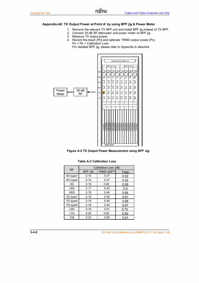
7/24/2019 Frx-3e Test v7.55 Issue1.06 June2014
http://slidepdf.com/reader/full/frx-3e-test-v755-issue106-june2014 84/214
Acceptance Test Fujitsu and Fujitsu Customer Use Only
3-4-8 On-Site Test & Maintenance (SNMP-SV: V7.54) issue 1.05
Appendix-A2: TX Output Power at Point A’ by using BPF jig & Power Meter
1. Remove the relevant TX BPF unit and install BPF jig instead of TX BPF.2. Connect 30 dB RF attenuator and power meter on BPF jig.3. Measure TX output power.4. Record the result (Pb) and calibrate TRMD output power (Po).
Po = Pb + Calibration LossFor detailed BPF jig, please refer to Appendix-A attached.
Figure A-2 TX Output Power Measurement using BPF Jig
Table A-2 Calibration Loss
PowerMeter
30-dBRF
SD1 3 5 9 7 5 3 1
SDP 2 4 8 6 4 2 P
RX1 3 5 9 7 5 3 1
RXP 2 4 8 6 4 2 P
TX3 5 9 7 5 3 1
TXP 2 4 8 6 4 2 P
TRMD
(W2)
TRMD
(W1)
TRMD(P)
Basic shelf
VE NT VE NT V EN T
TRMD
(W5)
TRMD
(W4)
TRMD
(W3)
TRMD
(W4)
TRMD(P)
TRMD
(W5)
TRMD
(W9)
TRMD
(W8)
TRMD
(W7)
TRMD
(W6)
TRADPT
TRADPT
TRMD
(W1)
TRMD
(W2)
TRMD
(W3)
V EN T VE NT VE NTVENT VENT
TRADPT
TRADPT
TRADPT
TRADPT
TRADPT
TRADPT
Antenna Port (Max. 8)
BEF (x4 m ax.) BEF (x4 m ax.)
Total0.52
0.52
0.56
0.6
0.64
0.67
0.68
0.67
0.70
0.820.91
0.18 0.49
11G 0.22 0.60
13G 0.23 0.68
L8G 0.19 0.51
7G type1 0.18 0.49
7G type4 0.19 0.49
7G type5
L6G 0.17 0.43
U6G 0.18 0.46
4G type2 0.15 0.37
5G 0.16 0.40
RF
BPF JIG TRMD ADPT4G type1 0.15 0.37
Calibration Loss (dB)

7/24/2019 Frx-3e Test v7.55 Issue1.06 June2014
http://slidepdf.com/reader/full/frx-3e-test-v755-issue106-june2014 85/214
Fujitsu and Fujitsu Customer Use Only Acceptance Test
On-Site Test & Maintenance (SNMP-SV: V7.54) issue 1.05 3-4-9
4.5 Transmit Spectrum for Fixed Modulation Order
This test is to check the TX output spectrum.
4.5.1 Equipment Required Spectrum analyzer.
HP 8491A Fixed attenuator (30 dB) or equivalent
4.5.2 Specifications
SDH interface: In accordance with ETSI EN303 217-2-2 V1.4.1 (2010-07)Limit B.3.2, System B.3, Class 5B for 30 MHz CSLimit C.3.2, System C.1, Class 5B for 40 MHz CS.
Ether interface: Same as above as FUJITSU specificationQAM order is QPSK/8/16/32/64/128/256/512QAM(*1)
(1) Discrete CW components at the symbol rate of 24.192 MHz (CWs):< 43 dB for the mean power level of the carrier
(2) Other discrete CW components (CW1 to CWn)< 9.5 dB exceeding the spectrum mask limit
Figure 4.2a Transmitter Output Spectrum (30 MHz CS)
Note-*1: In case of FPGA uploaded TRMD v1, available QAM order is 16/32/64/128/256QAM.
+2
CWs
CW1
CWn
-60
-50
0
0
-10
-20
-30
7510 20 30 40 50
Frequency Offset from Center of Frequency, F0
P o w e r S p e c t r a l D e n s i t y R e l a t i v e t o C e n t e r F r e q u e n c y ( d B )
Transmitter Spectrum Power Density
Reletive to Center Frequency (dB) for 128QAM System
+2/12
-10/14.5
-32/15.5
-36/17
-45/40
-55/50
-40

7/24/2019 Frx-3e Test v7.55 Issue1.06 June2014
http://slidepdf.com/reader/full/frx-3e-test-v755-issue106-june2014 86/214
Acceptance Test Fujitsu and Fujitsu Customer Use Only
3-4-10 On-Site Test & Maintenance (SNMP-SV: V7.54) issue 1.05
(1) Discrete CW components at the symbol rate of 32.064 MHz (CWs):< 43 dB for the mean power level of the carrier
(2) Other discrete CW components (CW1 to CWn)< 9.5 dB exceeding the spectrum mask limit
Figure 4.2b Transmitter Output Spectrum (40 MHz CS)
4.5.3 Test Procedure
1. Connect the spectrum analyzer to the CIR output port through the 30-dBhigh power fixed RF attenuator as shown in Figure 4.3.
2. Compare the test result to the specification (use delta markers or mask)
3. If the result is out of specification, tested TRMD should be replaced.4. Restore the connections.
+1
CWs
CW1 CWn
-60
-50
0
0
-10
-20
-30
Frequency Offset from Center of Frequency, F0
P o w e r S p e c t r a l D e n s i t y R e
l a t i v e t o C e n t e r F r e q u e n c y ( d B )
Transmitter Spectrum Power Density
Reletive to Center Frequency (dB) for 64QAM System
6010 20 30 40 50
-40
100
+1/14
-40/54
-55/67
-10/19.5
-35/24
NOTE:
This transmit spectrum specification is specified when TX Overdrive function isset to “DISABLED”. Please note that when TX Overdrive is set to “ENABLE”,this specification is not applicable.

7/24/2019 Frx-3e Test v7.55 Issue1.06 June2014
http://slidepdf.com/reader/full/frx-3e-test-v755-issue106-june2014 87/214
Fujitsu and Fujitsu Customer Use Only Acceptance Test
On-Site Test & Maintenance (SNMP-SV: V7.54) issue 1.05 3-4-11
Spectrum Analyzer setting
Parameter Setting
RF center frequency Spectrum center
Amplitude scale 10 dB/div
IF bandwidth 300 kHz for 40 MHz CS, 100 kHz for 30 MHz CS
Sweep width 200 MHz for 40 MHz CS, 150 MHz for 30 MHz CS
Scan time Automatic
Video bandwidth filter 300 Hz
Figure 4.3 Set up for Transmit Spectrum Measurement
SPECTRUM
ANALYZER
30dB ATT
SD1 3 5 9 7 5 3 1
SDP 2 4 8 6 4 2 P
RX1 3 5 9 7 5 3 1
RXP 2 4 8 6 4 2 P
TX1 3 5 9 7 5 3 1
TXP 2 4 8 6 4 2 P
L6G, 5+1 11G, 9+1
Antenna Port (Max. 8)
BEF (x4 max.) BEF (x4 m ax.)
TRADPT
TRADPT
TRADPT
TRADPT
TRADPT
TRADPT
TRADPT
TRADPT
TRMD(W1)
TRMD(W2)
TRMD(W3)
V EN T VE NT V EN TV EN T V EN T
TRMDP
TRMD(W5)
TRMD(W9)
TRMD(W8)
TRMD(W7)
TRMD(W6)
V EN T VE NT V EN T
TRMD(W5)
TRMD(W4)
TRMD(W3)
TRMD(W2)
TRMD(W1)
TRMDP
Basic shelf
BBINTFP
BBINTF(W1
)
BBINTF(W2
)
BBINTF(W3
)
BBINTF(W4
)
BBINTF(W5
)
TRMD(W4)
BBINTF(W9
)
BBINTF(W8
)
BBINTF(W7
)
BBINTF(W6
)
BBINTF(W5
)
BBINTF(W4
)
BBINTF(W3
)
BBINTF(W2
)
BBINTF(W1
)
BBINTFP
SVG
ESW
GESW
AUXINTF
AUXINTF
ETSI Rack (1,800 mm)
TERM

7/24/2019 Frx-3e Test v7.55 Issue1.06 June2014
http://slidepdf.com/reader/full/frx-3e-test-v755-issue106-june2014 88/214
Acceptance Test Fujitsu and Fujitsu Customer Use Only
3-4-12 On-Site Test & Maintenance (SNMP-SV: V7.54) issue 1.05
4.6 Transmit Spectrum for Dynamic Change of Modulation Order
This test is to check the TX output spectrum for dynamic change ofmodulation order for Native IP interface measured at TX BPF output..
4.6.1 Equipment Required
Spectrum analyzer.
HP 8491A Fixed attenuator (30 dB) or equivalent
4.6.2 Specifications
Limit: Clause 5.2.7 of ETSI EN303 217-2-2 V1.4.1(2010-07).Reference mode: Limit B.3.2, System B.3, Class 5B for 30 MHz CS
Limit C.3.2, System C.1, Class 5B for 40 MHz CSQAM change: QPSK/8/16/32/64/128/256/512QAM(*1)
(1) Discrete CW components at the symbol rate of 24.192 MHz (CWs):< 43 dB for the mean power level of the carrier
(2) Other discrete CW components (CW1 to CWn)< 9.5 dB exceeding the spectrum mask limit
Figure 4.3a Transmitter Spectrum for Dynamic Change of Modulation Order (30 MHz CS)
Note-*1: In case of FPGA uploaded TRMD v1, available QAM order is 16/32/64/128/256QAM.
+3
CWs
CW1
CWn
-60
50 75
Frequency Offset from Center of Frequency, F0
-40
-45/40
-50
-55/54 -55/75
0 10
Limits of Transmitter Power Spectral Density at Reference Point B'
+3/12
P o w e r S p e c t r a l D e n s i t y R e l a t i v e t o
C e n t e r F r e q u e n c y ( d B )
0
-10-10/14.5
-20
-30-32/15.5
-36/17
20 30 40

7/24/2019 Frx-3e Test v7.55 Issue1.06 June2014
http://slidepdf.com/reader/full/frx-3e-test-v755-issue106-june2014 89/214
Fujitsu and Fujitsu Customer Use Only Acceptance Test
On-Site Test & Maintenance (SNMP-SV: V7.54) issue 1.05 3-4-13
(1) Discrete CW components at the symbol rate of 32.064 MHz (CWs):< 43 dB for the mean power level of the carrier
(2) Other discrete CW components (CW1 to CWn)< 9.5 dB exceeding the spectrum mask limit
Figure 4.3b Transmitter Output Spectrum for Dynamic Change of Modulation Order (40 MHz CS)
4.5.3 Test Procedure
5. Connect the spectrum analyzer to the CIR output port through the 30-dBhigh power fixed RF attenuator as shown in Figure 4.4.
6. Compare the test result to the specification (use delta markers or mask)
7. If the result is out of specification, tested TRMD should be replaced.
8. Restore the connections.
NOTICE:
This transmit spectrum specification is specified when TX Overdrive function isset to “DISABLED”. Please note that when TX Overdrive is set to “ENABLE”,
this specification is not applicable.
+3
CWs
CW1
CWn
-60
60 100
Frequency Offset from Center of Frequency, F0 (MHz)
0 10 20 30 40 50
-35/24
-40-40/54
-50
-55/67 -55/100
Limits of Transmitter Power Spectral Density at Reference Point B'
+3/17
P o w e r S p e c t r a l D e n s i t y
R e l a t i v e t o C e n t e r F r e q u e n c y ( d B )
0
-10-10/19.5
-20
-30

7/24/2019 Frx-3e Test v7.55 Issue1.06 June2014
http://slidepdf.com/reader/full/frx-3e-test-v755-issue106-june2014 90/214
Acceptance Test Fujitsu and Fujitsu Customer Use Only
3-4-14 On-Site Test & Maintenance (SNMP-SV: V7.54) issue 1.05
Spectrum Analyzer setting
Parameter Setting
RF center frequency Spectrum center
Amplitude scale 10 dB/div
IF bandwidth 300 kHz for 40 MHz CS, 100 kHz for 30 MHz CS
Sweep width 200 MHz for 40 MHz CS, 150 MHz for 30 MHz CS
Scan time Automatic
Video bandwidth filter 300 Hz
Measurement Max-hold mode
Figure 4.4 Transmit Spectrum Measurement for Dynamic Change of Modulation Order
SPECTRUM
ANALYZER
30dB ATT
SD1 3 5 9 7 5 3 1
SDP 2 4 8 6 4 2 P
RX1 3 5 9 7 5 3 1
RXP 2 4 8 6 4 2 P
TX1 3 5 9 7 5 3 1
TXP 2 4 8 6 4 2 P
L6G, 5+1 11G, 9+1
Antenna Port (Max. 8)
BEF (x4 max.) BEF (x4 max.)
TRADPT
TRADPT
TRADPT
TRADPT
TRADPT
TRADPT
TRADPT
TRADPT
TRMD(W1)
TRMD(W2)
TRMD(W3)
V EN T VE NT V EN TV EN T V EN T
TRMD(P)
TRMD(W5)
TRMD(W9)
TRMD(W8)
TRMD(W7)
TRMD(W6)
V EN T VE NT V EN T
TRMD(W5)
TRMD(W4)
TRMD(W3)
TRMD(W2)
TRMD(W1)
TRMD(P)
Basic shelf
BBINTF(P)
BBINT
F(W1)
BBINT
F(W2)
BBINT
F(W3)
BBINT
F(W4)
BBINT
F(W5)
TRMD(W4)
BBINT
F(W9)
BBINT
F(W8)
BBINT
F(W7)
BBINT
F(W6)
BBINT
F(W5)
BBINT
F(W4)
BBINT
F(W3)
BBINT
F(W2)
BBINT
F(W1)
BBINTF(P)
SVG
ESW
GESW
AUXINTF
AUXINTF
ETSI Rack (1,800 mm)
TERM
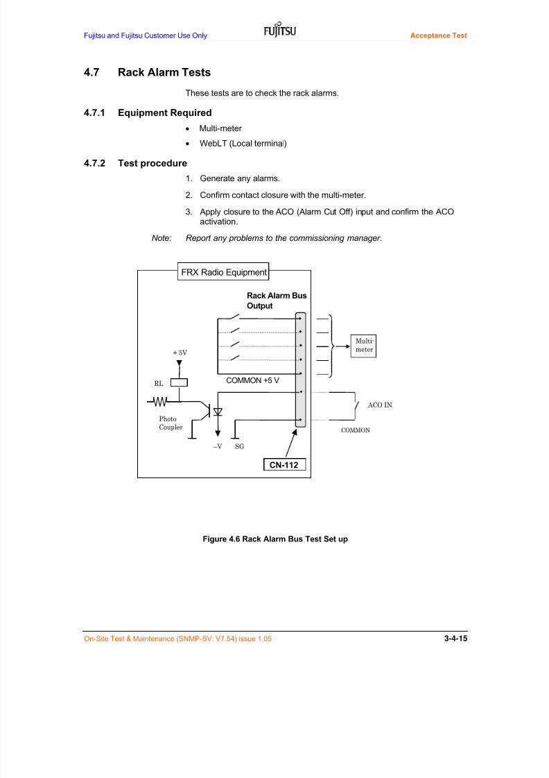
7/24/2019 Frx-3e Test v7.55 Issue1.06 June2014
http://slidepdf.com/reader/full/frx-3e-test-v755-issue106-june2014 91/214
Fujitsu and Fujitsu Customer Use Only Acceptance Test
On-Site Test & Maintenance (SNMP-SV: V7.54) issue 1.05 3-4-15
4.7 Rack Alarm Tests
These tests are to check the rack alarms.
4.7.1 Equipment Required
Multi-meter
WebLT (Local terminal)
4.7.2 Test procedure
1. Generate any alarms.
2. Confirm contact closure with the multi-meter.
3. Apply closure to the ACO (Alarm Cut Off) input and confirm the ACOactivation.
Note: Report any problems to the commissioning manager.
Figure 4.6 Rack Alarm Bus Test Set up
Rack Alarm Bus
Output
+ 5V
RL
SG – V
Photo
Coupler
COMMON +5 V
COMMON
Multi-
meter
ACO IN
FRX Radio Equipment
CN-112

7/24/2019 Frx-3e Test v7.55 Issue1.06 June2014
http://slidepdf.com/reader/full/frx-3e-test-v755-issue106-june2014 92/214
Acceptance Test Fujitsu and Fujitsu Customer Use Only
3-4-16 On-Site Test & Maintenance (SNMP-SV: V7.54) issue 1.05
Table 4.6a Connector Number and Type for RAB.
Use Access Name Connector No. on BWB Type of Connector
RAB UIA-CNxx Dsub 15
Table 4.6b Connector PIN assignment for RAB
PINNo. Description Remarks
PINNo. Description Remarks
8 COMMON
15 ACO IN ACO Ground line 7 VIS MN Visible Miner alarm
14 ACO IN Alarm Cut Off IN 6 AUD MN Audible Miner alarm
13 NE ALM-N NE alarm (N) 5 VIS MJ Visible Major alarm
12 NE ALM-C NE alarm (C) 4 AUD MJ Audible Major alarm
11 RAB-MNT Maintenance 3 VIS CR Visible Critical alarm
10 VIS WR Visible Warning 2 AUD CR Audible Critical alarm
9 AUD WR Audible Warning 1 FG Frame Ground
Note-1*: When RAB audible and visible function is ENABLED, Pin-1 to Pin-15 isavailable. If not, only Pin-13 to 15 is applicable.
4.8 Change the Equipment to In-Service
After completion of Station Tests, change the Maintenance State to In-Service (IS) state.
9 1
15
8
7/24/2019 Frx-3e Test v7.55 Issue1.06 June2014
http://slidepdf.com/reader/full/frx-3e-test-v755-issue106-june2014 93/214
Fujitsu and Fujitsu Customer use Only Acceptance Test
On-Site Test & Maintenance (SNMP-SV: V7.54) issue 1.05
5 Hop Tests
This section details the procedures to be carried out after station tests havebeen completed and the FRX-3E has been connected to the network.
NOTICE:
1. DO NOT attempt to re-tune any adjustment point, if the test
result is within the specification.
2. CONFIRM that return loss result of antenna system delivered
from installation team is smoothly flat and there are no spikesand beard-like distortion or something within allocated RF
band.
3. TAKE CARE that loose connection between radio equipmentand waveguide feeder at DUP/ADPT port, feeder and antenna
and feeder bend beyond permissible limit may induce the IM3interference.
4. When space diversity reception is applied, CONFIRM that
feeder length difference between main and SD receiver pathand/or main and cross-polarized SD receiver should be within30 m (up to 150 ns). If not, feeder length adjustment should becarried out before testing.
5. When cross polarized operation (CCDP) is applied, CONFIRMthat feeder length difference between V- and H- polarized pathshould be within 30 m (up to 150 ns). If not, feeder length
adjustment should be carried out before testing.
6. Hop test will be carried out by turns from Section 5.1 to 5.12 atthe time of first commissioning test, TRMD & card replacement,
RF channel expansion and so on.
.
. 5.1 Change the Equipment to Maintenance State
Change the specific RF AID to test to Maintenance State by WebLT.
Menu: Provisioning > Service State
Set Provisioning Value for specific AID to test to IS-MT from IS
Operate > “Command will be operated, OK? > OK > “CommandRequest was received” > Closed
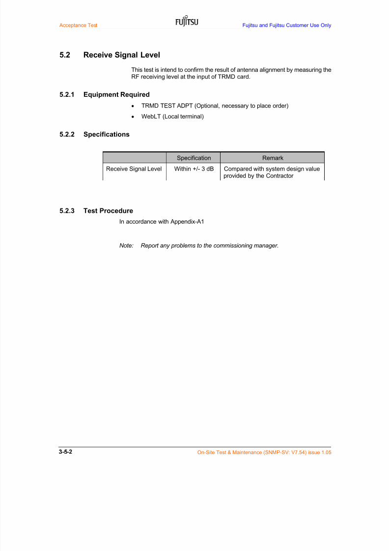
7/24/2019 Frx-3e Test v7.55 Issue1.06 June2014
http://slidepdf.com/reader/full/frx-3e-test-v755-issue106-june2014 94/214
Acceptance Test Fujitsu and Fujitsu Customer Use Only
On-Site Test & Maintenance (SNMP-SV: V7.54) issue 1.05
5.2 Receive Signal Level
This test is intend to confirm the result of antenna alignment by measuring theRF receiving level at the input of TRMD card.
5.2.1 Equipment Required
TRMD TEST ADPT (Optional, necessary to place order)
WebLT (Local terminal)
5.2.2 Specifications
Specification Remark
Receive Signal Level Within +/- 3 dB Compared with system design valueprovided by the Contractor
5.2.3 Test Procedure
In accordance with Appendix-A1
Note: Report any problems to the commissioning manager.
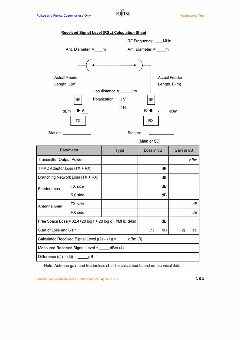
7/24/2019 Frx-3e Test v7.55 Issue1.06 June2014
http://slidepdf.com/reader/full/frx-3e-test-v755-issue106-june2014 95/214
Fujitsu and Fujitsu Customer use Only Acceptance Test
On-Site Test & Maintenance (SNMP-SV: V7.54) issue 1.05
□
□

7/24/2019 Frx-3e Test v7.55 Issue1.06 June2014
http://slidepdf.com/reader/full/frx-3e-test-v755-issue106-june2014 96/214
Acceptance Test Fujitsu and Fujitsu Customer Use Only
On-Site Test & Maintenance (SNMP-SV: V7.54) issue 1.05
Appendix-A1: Receiver Signal Level at Point A by using TRMD jig & Power Meter
1. Remove the relevant TRMD card and install TRMD jig instead of TRMD.2. Connect power meter with RX and SD RX port on TRMD jig.3. Measure received signal level (RSL).4. Record the result (RSLa) and calibrate TRMD RF IN power (RSL).
RSL = RSLa + Calibration LossFor detailed TRMD jig, please refer to Appendix-A attached.
Figure A-1 RSL Measurement using BPF Jig
Table A-1 Calibration Loss
SD1 3 5 9 7 5 3 1
SDP 2 4 8 6 4 2 P
RX1 3 5 9 7 5 3 1
RXP 2 4 8 6 4 2 P
TX1 3 5 9 7 5 3 1
TXP 2 4 8 6 4 2 P
TRM
D(W3)
TRM
D(W2)
TRM
D(W1)
TR
MD(P)
Basic shelf
TRM
D(W9)
TRM
D(W8)
TRM
D(W7)
TRM
D(W6)
TRM
D(W5)
TRM
D(W4)
TRMD(P)
TRMDJIG
TRM
D(W2)
TRM
D(W3)
TRM
D(W4)
TRM
D(W5)
TRADPT
TRADPT
VEN T VEN T VEN T VEN T VEN T VEN T VEN T VEN T
TRADPT
TRADPT
TRADPT
TRADPT
TRADPT
TRADPT
Antenna Port (Max. 8)
BEF (x4 m ax.) BEF (x4 m ax.)
4G type2 0.20
5G 0.21
RF TRMD JIG
4G type1 0.20
Calibration Loss (dB)
7G type1 0.26
7G type4 0.26
L6G 0.24
U6G 0.25
11G 0.3413G 0.36
7G type5 0.26
L8G 0.27

7/24/2019 Frx-3e Test v7.55 Issue1.06 June2014
http://slidepdf.com/reader/full/frx-3e-test-v755-issue106-june2014 97/214
Fujitsu and Fujitsu Customer use Only Acceptance Test
On-Site Test & Maintenance (SNMP-SV: V7.54) issue 1.05
5.3 Delay Equalizer Select
This test is intended to set the delay equalization on WebLT for RF frequencyband used.
5.3.1 Equipment Required
WebLT (Local terminal)
5.3.3 Test Procedure
Provisioning > Delay Equalizer Select
1. Select Provisioning Value for GP1-P in accordance with Table 5.1 below.
2. Click “Operate” button to execute.
Table 5.1 Set-up Value
ProvisioningValue
Description
NoneWhen 40 MHz CS system is applied or no lower and upper first
adjacent RF CHs are allocated for 30 MHz CS system.
Lower When lower first adjacent RF CH is allocated for 30 MHz CS system.
Upper When upper first adjacent RF CH is allocated for 30 MHz CS system.
BothWhen both lower and upper first adjacent RF CHs are allocated
for 30 MHz CS system.
Operate > “Command will be operated, OK?” > OK > “CommandRequest was received. > Closed.
3. Repeat item 1 to item 2 for all specific AIDs.

7/24/2019 Frx-3e Test v7.55 Issue1.06 June2014
http://slidepdf.com/reader/full/frx-3e-test-v755-issue106-june2014 98/214
Acceptance Test Fujitsu and Fujitsu Customer Use Only
On-Site Test & Maintenance (SNMP-SV: V7.54) issue 1.05
5.4 Auto IF-IF Response Adjustment
This test is to perform the IF-IF characteristics test for TX-RX overall includingantenna system at normal propagation condition.
5.4.1 Equipment Required
WebLT (Local terminal)
5.4.4 Test Procedure
1. Logon to the NE(Network Element) by WebLT.
Condition > IF Response
2. Confirm the status colors of amplitude alarm1/2 and delay alarm1/2.
3. When green indications appear for all specific AIDs, skip to next test item.
4. When red indication appears for some AID, confirm that above Section5.3 Delay Equalizer Select of specific AID in red is made correctly or not.
5. If Delay Equalizer Select is correct, it is considered that near-end orfar-end TRMD card and/or feeder system have troubled.
6. Replace TRMD card of specific AID in red at near-end or far-end stationand confirm that IF Response indication turns to green or not.
7. If not, return loss test result of antenna feeder system both near-end andfar-end station from construction team will be checked and tested again, ifnecessary. For details, refer to Chapter 4, Section 3 Trouble Shooting.
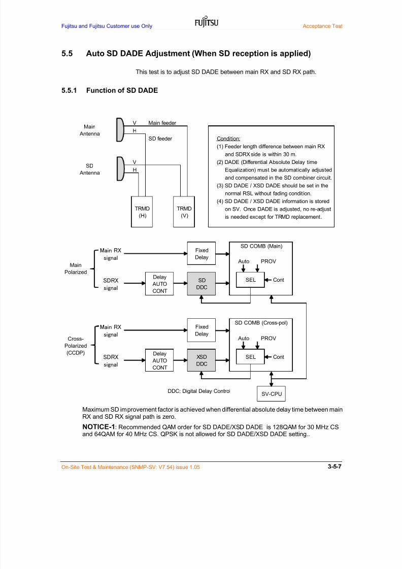
7/24/2019 Frx-3e Test v7.55 Issue1.06 June2014
http://slidepdf.com/reader/full/frx-3e-test-v755-issue106-june2014 99/214
Fujitsu and Fujitsu Customer use Only Acceptance Test
On-Site Test & Maintenance (SNMP-SV: V7.54) issue 1.05
5.5 Auto SD DADE Adjustment (When SD reception is applied)
This test is to adjust SD DADE between main RX and SD RX path.
5.5.1 Function of SD DADE
Maximum SD improvement factor is achieved when differential absolute delay time between mainRX and SD RX signal path is zero.
NOTICE-1: Recommended QAM order for SD DADE/XSD DADE is 128QAM for 30 MHz CS
and 64QAM for 40 MHz CS. QPSK is not allowed for SD DADE/XSD DADE setting..
V Main feeder
H
SD feeder Condition:
(1) Feeder length difference between main RX
and SDRX side is within 30 m.
V (2) DADE (Differential Absolute Delay time
H Equalization) must be automatically adjusted
and compensated in the SD combiner circuit.
(3) SD DADE / XSD DADE should be set in the
normal RSL without fading condition.
(4) SD DADE / XSD DADE information is stored
on SV. Once DADE is adjusted, no re-adjust
is needed except for TRMD replacement.
DDC: Digital Delay Control
TRMD
(H)
TRMD
(V)
Main
Antenna
SD
Antenna
Delay
AUTO
CONT
SD
DDC
Fixed
Delay
Delay
AUTO
CONT
XSD
DDC
SEL Cont
SEL Cont
SV-CPU
SD COMB (Main)
Fixed
Delay
SD COMB (Cross-pol)
Auto PROV
Auto PROV
Main RX
signal
SDRX
signal
Main
Polarized
Cross-
Polarized(CCDP)
Main RX
signal
SDRX
signal
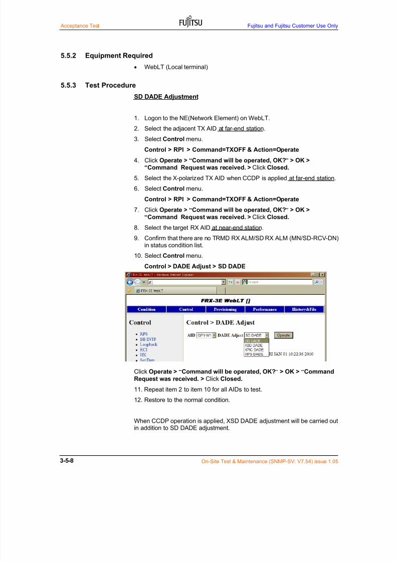
7/24/2019 Frx-3e Test v7.55 Issue1.06 June2014
http://slidepdf.com/reader/full/frx-3e-test-v755-issue106-june2014 100/214
Acceptance Test Fujitsu and Fujitsu Customer Use Only
On-Site Test & Maintenance (SNMP-SV: V7.54) issue 1.05
5.5.2 Equipment Required
WebLT (Local terminal)
5.5.3 Test Procedure
SD DADE Adjustment
1. Logon to the NE(Network Element) on WebLT.
2. Select the adjacent TX AID at far-end station.
3. Select Control menu.
Control > RPI > Command=TXOFF & Action=Operate
4. Click Operate > “Command will be operated, OK?” > OK >
“Command Request was received. > Click Closed.
5. Select the X-polarized TX AID when CCDP is applied at far-end station.
6. Select Control menu.
Control > RPI > Command=TXOFF & Action=Operate
7. Click Operate > “Command will be operated, OK?” > OK >
“Command Request was received. > Click Closed.
8. Select the target RX AID at near-end station.
9. Confirm that there are no TRMD RX ALM/SD RX ALM (MN/SD-RCV-DN)in status condition list.
10. Select Control menu.
Control > DADE Adjust > SD DADE
Click Operate > “Command will be operated, OK?” > OK > “Command
Request was received. > Click Closed.
11. Repeat item 2 to item 10 for all AIDs to test.
12. Restore to the normal condition.
When CCDP operation is applied, XSD DADE adjustment will be carried out
in addition to SD DADE adjustment.

7/24/2019 Frx-3e Test v7.55 Issue1.06 June2014
http://slidepdf.com/reader/full/frx-3e-test-v755-issue106-june2014 101/214
Fujitsu and Fujitsu Customer use Only Acceptance Test
On-Site Test & Maintenance (SNMP-SV: V7.54) issue 1.05
XSD DADE Adjustment (When CCDP operation is applied)
1. Logon to the NE(Network Element) by WebLT.
2. Select the target TX AID at far-end station.
3. Select Control menu.
Control > RPI > Command=TXOFF & Action=Operate
4. Click Operate > “Command will be operated, OK?” > OK >
“Command Request was received. > Click Closed.
5. Select the adjacent TX AID at far-end station.
6. Select Control menu.
Control > RPI > Command=TXOFF & Action=Operate
7. Click Operate > “Command will be operated, OK?” > OK >“Command Request was received. > Click Closed.
8. Confirm that there are no TRMD RX ALM/SD RX ALM (MN/SD-RCV-DN)in status condition list.
9. Select the target AID at near-end station.
10. Select Control menu.
Menu: Control > DADE Adjust > XSD DADE
Click Operate > “Command will be operated, OK?” > OK > “Command
Request was received. > Click Closed.
11. Repeat item 1 to item 10 for all AIDs to test.
12. Restore to the normal condition.

7/24/2019 Frx-3e Test v7.55 Issue1.06 June2014
http://slidepdf.com/reader/full/frx-3e-test-v755-issue106-june2014 102/214
Acceptance Test Fujitsu and Fujitsu Customer Use Only
On-Site Test & Maintenance (SNMP-SV: V7.54) issue 1.05
5.6 Auto XPIC DADE Adjustment (When CCDP operation is applied)
This test is to adjust XPIC DADE’ing at normal propagation condition.
5.6.1 Function of XPIC DADE
Maximum XPIC improvement factor is achieved when differential absolute delay time between
main path and compensating path is zero.
NOTICE-1: QAM order both V/H-polarization should be same when setting and recommendedQAM is 128QAM for 30 MHz CS & 64QAM for 40 MHz CS. QPSK is not allowed for XPIC DADE.
Main pol. signal Main signal + =
Interfering signal
Main antenna
V V
Main path
H Varying amplitude
H Inverse polarity
X-pol signal
(Interfering signal
for main pol. signal
Compensating path
Main path signal
Compensating path signal
Condition:
(1) Feeder length difference between main RX
and X-polarized RX side is within 30 m.
(2) Prior XPIC DADE adjustment, main TX power
set toOFF
in a far-end station(3) XPIC DADE (Differential Absolute Delay time
Equalization) must be automatically adjusted
and compensated in the XPIC circuit .
(4) XPIC DADE should be set in the normal RSL
without fading condition.
(5) XPIC DADE information is stored on SV.
Once XPIC DADE is adjusted, no re-adjust
is needed except for TRMD card replacement.
TRMD RX(main)
XPIC
XPIC improvement
SV-CPU
Fixed
Delay
XPIC of TRMD RX(main)
Auto PROV
XPIC
DEM
Delay
AUTO
CONT
XDDCSEL Cont
Incoming main pol. signal
Incoming X-pol signalDEM
TRMD RX(X-pol)

7/24/2019 Frx-3e Test v7.55 Issue1.06 June2014
http://slidepdf.com/reader/full/frx-3e-test-v755-issue106-june2014 103/214
Fujitsu and Fujitsu Customer use Only Acceptance Test
On-Site Test & Maintenance (SNMP-SV: V7.54) issue 1.05
5.6.2 Equipment Required
WebLT (Local terminal)
5.6.3 Test Procedure
1. Logon to the NE(Network Element) by WebLT.
2. Select the target AID at far-end station.
3. Select Control menu.
Menu: Control > RPI > Command=TXOFF & Action=Operate
Click Operate > “Command will be operated, OK?” > OK >
“Command Request was received. > Click Closed.
4. Select the X-polarized AID at far-end station.
5. Select Provisioning menu.
Provisioning > TX Setting > TPC=MTPC > MTPC=2 &Action=Operate
Click Operate > “Command will be operated, OK?” > OK >
“Command Request was received. > Click Closed.
6. Select the target AID and X-polarized AID at near-end station.
7. Confirm that RSL is higher than -85 dBm at TRMD RF input without XPICDADE ALM (XPIC-LOS-MN/SD).
8. Select Provisioning menu.
Provisioning > RSPI > Space Diversity=Disable & Action=Operate
Click Operate > “Command will be operated, OK?” > OK >
“Command Request was received. > Click Closed.
9. Set Control menu at Near-End station.
Menu: Control > DADE Adjust > XPIC DADE
10. Repeat item 2 and 9 for all AIDs to test and restore to the normal condition.
NOTICE

7/24/2019 Frx-3e Test v7.55 Issue1.06 June2014
http://slidepdf.com/reader/full/frx-3e-test-v755-issue106-june2014 104/214
Acceptance Test Fujitsu and Fujitsu Customer Use Only
3-5-12 On-Site Test & Maintenance (SNMP-SV: V7.54) issue 1.05
5.7 Auto RPS DADE Adjustment
This test is intended to adjust RPS DADE protection channel and any ofworking channels at normal propagation condition. RPS DADE adjustment is
made automatically for all working CHs without measuring equipment.
5.7.1 Equipment Required
WebLT (Local terminal)
5.7.2 Test Procedure
1. Logon to the NE(Network Element) by WebLT.
2. Select Control menu3. Select the target working AID.
Control > RPS > Direction = Bi-Direction > Action = Operate Forced
4. Select the target working AID.
Control > DADE Adjust > RPS DADE
Click Operate > “Command will be operated, OK?” > OK > “CommandRequest was received. > Click Closed.
5. Select the target working AID.
Control > RPS > Direction = Bi-Direction > Action = Release Forced
6. Repeat item 3 to item 5 for all working AIDs.
NOTICE*: QAM order both working and protection channel should be same when setting andrecommended QAM is 128QAM for 30 MHz CS & 64QAM for 40 MHz CS.
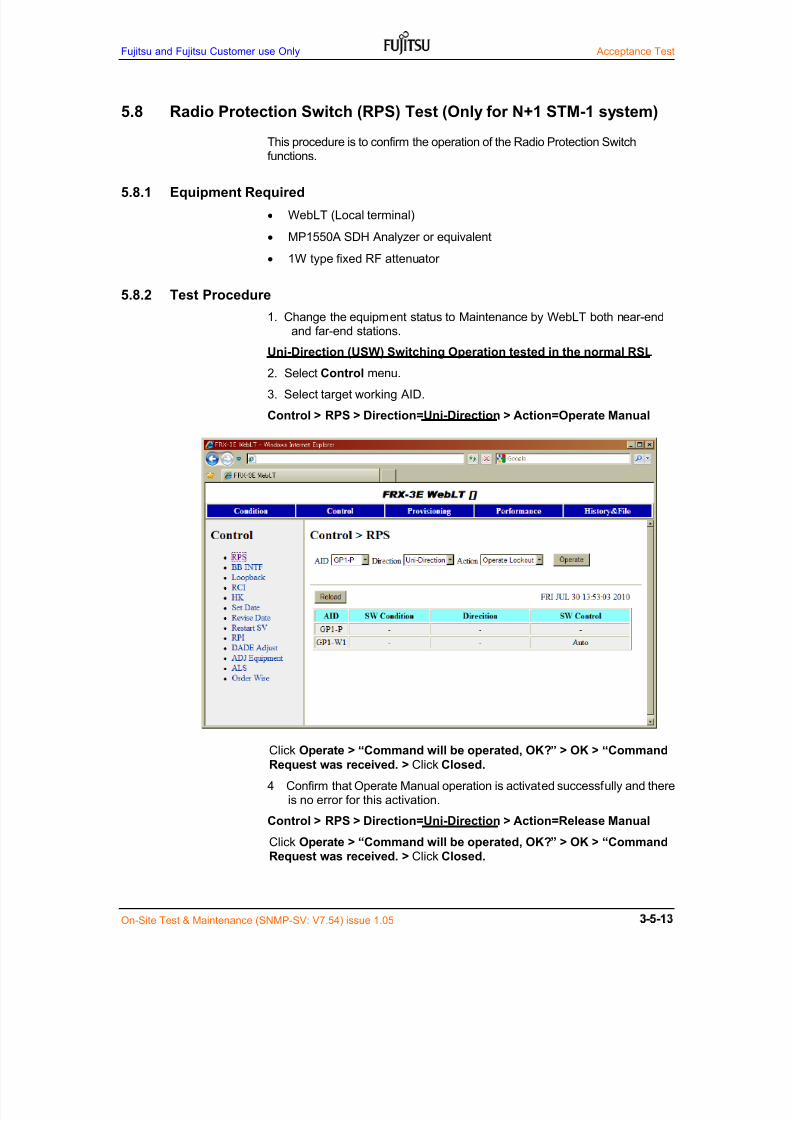
7/24/2019 Frx-3e Test v7.55 Issue1.06 June2014
http://slidepdf.com/reader/full/frx-3e-test-v755-issue106-june2014 105/214
Fujitsu and Fujitsu Customer use Only Acceptance Test
On-Site Test & Maintenance (SNMP-SV: V7.54) issue 1.05
5.8 Radio Protection Switch (RPS) Test (Only for N+1 STM-1 system)
This procedure is to confirm the operation of the Radio Protection Switchfunctions.
5.8.1 Equipment Required
WebLT (Local terminal)
MP1550A SDH Analyzer or equivalent
1W type fixed RF attenuator
5.8.2 Test Procedure
1. Change the equipment status to Maintenance by WebLT both near-endand far-end stations.
Uni-Direction (USW) Switching Operation tested in the normal RSL
2. Select Control menu.
3. Select target working AID.
Control > RPS > Direction=Uni-Direction > Action=Operate Manual
Click Operate > “Command will be operated, OK?” > OK > “Command
Request was received. > Click Closed.
4 Confirm that Operate Manual operation is activated successfully and thereis no error for this activation.
Control > RPS > Direction=Uni-Direction > Action=Release Manual
Click Operate > “Command will be operated, OK?” > OK > “Command
Request was received. > Click Closed.
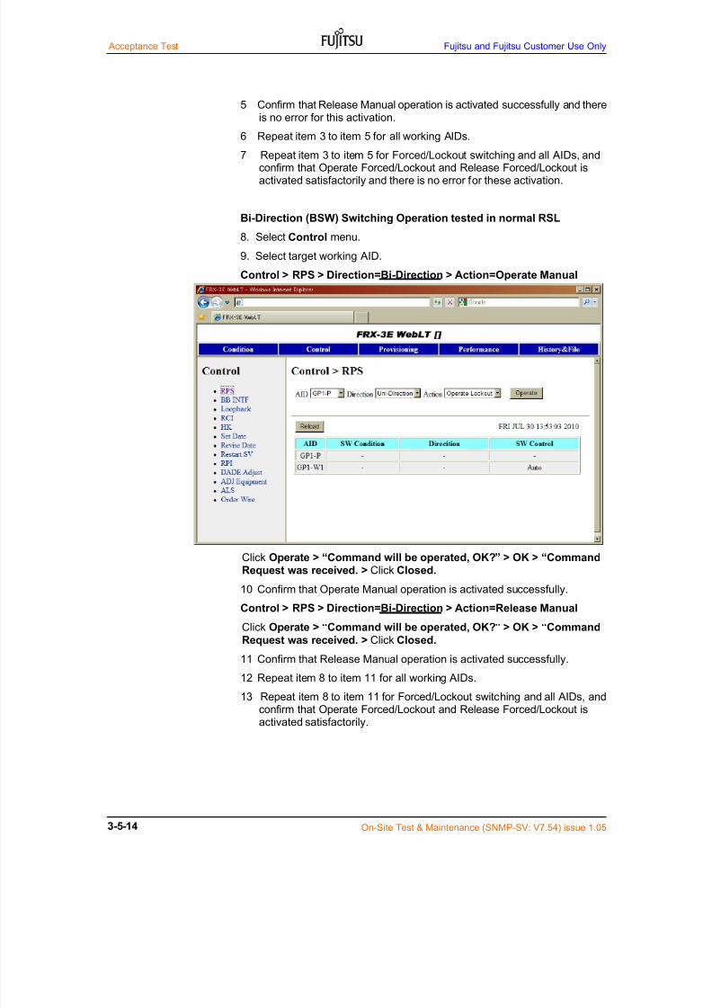
7/24/2019 Frx-3e Test v7.55 Issue1.06 June2014
http://slidepdf.com/reader/full/frx-3e-test-v755-issue106-june2014 106/214
Acceptance Test Fujitsu and Fujitsu Customer Use Only
On-Site Test & Maintenance (SNMP-SV: V7.54) issue 1.05
5 Confirm that Release Manual operation is activated successfully and thereis no error for this activation.
6 Repeat item 3 to item 5 for all working AIDs.
7 Repeat item 3 to item 5 for Forced/Lockout switching and all AIDs, andconfirm that Operate Forced/Lockout and Release Forced/Lockout isactivated satisfactorily and there is no error for these activation.
Bi-Direction (BSW) Switching Operation tested in normal RSL
8. Select Control menu.
9. Select target working AID.
Control > RPS > Direction=Bi-Direction > Action=Operate Manual
Click Operate > “Command will be operated, OK?” > OK > “CommandRequest was received. > Click Closed.
10 Confirm that Operate Manual operation is activated successfully.
Control > RPS > Direction=Bi-Direction > Action=Release ManualClick Operate > “Command will be operated, OK?” > OK > “Command
Request was received. > Click Closed.
11 Confirm that Release Manual operation is activated successfully.
12 Repeat item 8 to item 11 for all working AIDs.
13 Repeat item 8 to item 11 for Forced/Lockout switching and all AIDs, andconfirm that Operate Forced/Lockout and Release Forced/Lockout isactivated satisfactorily.
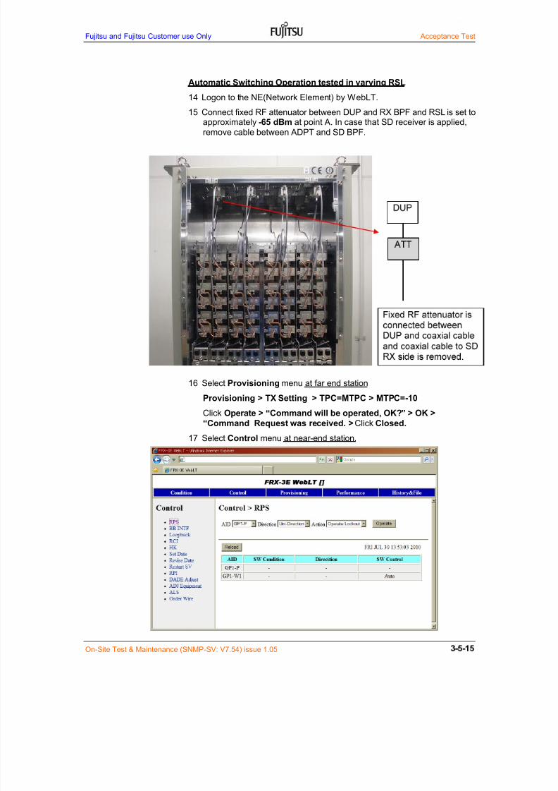
7/24/2019 Frx-3e Test v7.55 Issue1.06 June2014
http://slidepdf.com/reader/full/frx-3e-test-v755-issue106-june2014 107/214
Fujitsu and Fujitsu Customer use Only Acceptance Test
On-Site Test & Maintenance (SNMP-SV: V7.54) issue 1.05
Automatic Switching Operation tested in varying RSL
14 Logon to the NE(Network Element) by WebLT.
15 Connect fixed RF attenuator between DUP and RX BPF and RSL is set to
approximately -65 dBm at point A. In case that SD receiver is applied,remove cable between ADPT and SD BPF.
16 Select Provisioning menu at far end station
Provisioning > TX Setting > TPC=MTPC > MTPC=-10
Click Operate > “Command will be operated, OK?” > OK >
“Command Request was received. > Click Closed.
17 Select Control menu at near-end station.

7/24/2019 Frx-3e Test v7.55 Issue1.06 June2014
http://slidepdf.com/reader/full/frx-3e-test-v755-issue106-june2014 108/214
Acceptance Test Fujitsu and Fujitsu Customer Use Only
On-Site Test & Maintenance (SNMP-SV: V7.54) issue 1.05
18 Confirm that Uni-Directional Automatic switching is activated successfullyand there is no error for switching activation.
19 Select Provisioning menu at far end station
Provisioning > TX Setting > TPC=MTPC > MTPC=0
Click Operate > “Command will be operated, OK?” > OK >
“Command Request was received. > Click Closed.
20 Select Control menu at near-end station.
21 Confirm that Uni-Directional Automatic switching is restored successfullyand there is no error for switching restoration.
22 Repeat item 16 to item 21 for all working AIDs.
23 Finally fix RF attenuator is removed and set to normal connection.

7/24/2019 Frx-3e Test v7.55 Issue1.06 June2014
http://slidepdf.com/reader/full/frx-3e-test-v755-issue106-june2014 109/214
Fujitsu and Fujitsu Customer use Only Acceptance Test
On-Site Test & Maintenance (SNMP-SV: V7.54) issue 1.05
Figure 5.4 Automatic Switching RPS Test Set up
Web LT
SD1 3 5 1 3 5 7 9
SDP 2 4 P 2 4 6 8
RX 1 3 5 1 3 5 7 9
RXP 2 4 P 2 4 6 8
TX1 3 5 1 3 5 7 9
TXP 2 4 P 2 4 6 8
L6G, 5+1 11G, 9+1
TERMExt-BB shelf
BRSW
BRSW
BRSW
BRSW
BBINTF(P)
BBINTF(W1)
Basic shelf
ETSI Rack (2,200 mm)
BBINTF(W7)
BBINTF(W8)
BBINTF(W6)
BRSW
BBINTF(W2)
BBINTF(W3)
BBINTF(W4)
BBINTF(W9)
BBINTF(W4)
BBINTF(W5)
BBINTF(P)
BBINTF(W1)
BBINTF(W5)
BBINTF(W2)
BBINTF(W3)
BRSW
BRSW
BRSW
BRSW
BRSW
BRSW
BRSW
BRSW
BRSW
BRSW
BRSW
TERM
BBEXTADPT
BBEXTADPT
GESW
GESW
BBINTF(W8)
BBINTF(W9)
BBINTF(W2)
BBINTF(W3)
BBINTF(W4)
SV
AUXINTF
AUXINTF
BBINTF(W5)
BBINTF(W6)
BBINTF(W7)
BBINTF(W2)
BBINTF(W3)
BBINTF(W4)
BBINTF(W5)
BBINTF(P)
BBINTF(W1)
BBINTF(P)
BBINTF(W1)
TRMD(W8)
TRMD(W9)
TRMD(W2)
TRMD(W3)
TRMD(W4)
TRMD(W5)
TRMD(W6)
TRMD(W7)
VENTV EN T V EN T V EN T V EN T
TRMD(W2)
TRMD(W3)
TRMD(W4)
TRMD(W5)
TRMD(P)
TRADPT
TRMD(P)
TRMD(W1)
V ENT V ENT V ENT
TRMD(W1)
Antenna Port (Max. 8)
BEF (x4 max.) BEF (x4 max.)
TRADPT
TRADPT
TRADPT
TRADPT
TRADPT
TRADPT
TRADPT
SDH Analyser
SDH Analyser

7/24/2019 Frx-3e Test v7.55 Issue1.06 June2014
http://slidepdf.com/reader/full/frx-3e-test-v755-issue106-june2014 110/214
Acceptance Test Fujitsu and Fujitsu Customer Use Only
On-Site Test & Maintenance (SNMP-SV: V7.54) issue 1.05
5.9 Dynamic Change of Modulation Order Test (GESW v2 only)
This procedure is to confirm the dynamic change of modulation order operationfor Native IP interface.
5.9.1 Equipment Required
WebLT (Local terminal)
5.9.2 Test Procedure
1. Change the equipment status to Maintenance by WebLT both near-endand far-end stations.
Provisioning > Modulation Config
2. Select AID, SDH/Ether=Ether, Mode=FIX and T-QAM.
Operate > “Command will be operated, OK?” > OK > “Command
Request was received. > Closed.
5. Confirm hop performance both down-stream and up-stream is normal onperformance monitor screen.
Dynamic change of modulation order test
6. Change modulation order on WebLT from QPSK to higher modulationorder specified by license key one-by-one in the W1 of M+0 channel.
7. Confirm that hop performance both down stream and up-stream is normalon performance monitoring screen on WebLT.
8. Configure test equipment as per Figure 5.5.
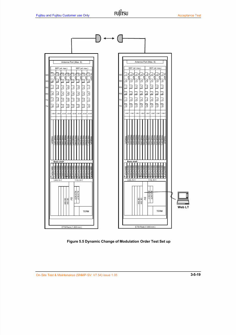
7/24/2019 Frx-3e Test v7.55 Issue1.06 June2014
http://slidepdf.com/reader/full/frx-3e-test-v755-issue106-june2014 111/214
Fujitsu and Fujitsu Customer use Only Acceptance Test
On-Site Test & Maintenance (SNMP-SV: V7.54) issue 1.05
Figure 5.5 Dynamic Change of Modulation Order Test Set up
Web LT
SD1 3 5 9 7 5 3 1
SDP 2 4 8 6 4 2 P
RX1 3 5 9 7 5 3 1
RXP 2 4 8 6 4 2 P
TX1 3 5 9 7 5 3 1
TXP 2 4 8 6 4 2 P
L6G, 5+1 11G, 9+1
AUXINTF
AUXINTF
ETSI Rack (1,800 mm )
TERM
BBINTF(W3)
BBINTF(W2)
BBINTF(W1)
BBINTF(P)
SVG
E
SW
GE
SW
BBINTF(W9)
BBINTF(W8)
BBINTF(W7)
BBINTF(W6)
BBINTF(W5)
BBINTF(W4)
TRMD(W2)
TRMD(W1)
TRMD(P)
Basic shelf
BBINTF(P)
BBINTF(W1)
BBINTF(W2)
BBINTF(W3)
BBINTF(W4)
BBINTF(W5)
VE NT VE NT VE NT
TRMD(W5)
TRMD(W4)
TRMD(W3)
TRMD(W4)
TRMD(P)
TRMD(W5)
TRMD(W9)
TRMD(W8)
TRMD(W7)
TRMD(W6)
TRADPT
TRADPT
TRMD(W1)
TRMD(W2)
TRMD(W3)
VE NT VE NT VE NTVENT VENT
TRADPT
TRADPT
TRADPT
TRADPT
TRADPT
TRADPT
Antenna Port (Max. 8)
BEF (x4 max.) BEF (x4 max.)
SD1 3 5 9 7 5 3 1
SDP 2 4 8 6 4 2 P
RX1 3 5 9 7 5 3 1
RXP 2 4 8 6 4 2 P
TX1 3 5 9 7 5 3 1
TXP 2 4 8 6 4 2 P
L6G, 5+1 11G, 9+1
AUXINTF
AUXINTF
ETSI Rack (1,800 mm )
TERM
BBINTF(W3)
BBINTF(W2)
BBINTF(W1)
BBINTF(P)
SVG
ESW
GESW
BBINTF(W9)
BBINTF(W8)
BBINTF(W7)
BBINTF(W6)
BBINTF(W5)
BBINTF(W4)
TRMD(W2)
TRMD(W1)
TRMD(P)
Basic shelf
BBINTF(P)
BBINTF(W1)
BBINTF(W2)
BBINTF(W3)
BBINTF(W4)
BBINTF(W5)
V EN T V EN T V EN T
TRMD(W5)
TRMD(W4)
TRMD(W3)
TRMD(W4)
TRMD(P)
TRMD(W5)
TRMD(W9)
TRMD(W8)
TRMD(W7)
TRMD(W6)
TRADPT
TRADPT
TRMD(W1)
TRMD(W2)
TRMD(W3)
V EN T V EN T V EN TVENT VENT
TRADPT
TRADPT
TRADPT
TRADPT
TRADPT
TRADPT
Antenna Port (Max. 8)
BEF (x4 max.) BEF (x4 max.)

7/24/2019 Frx-3e Test v7.55 Issue1.06 June2014
http://slidepdf.com/reader/full/frx-3e-test-v755-issue106-june2014 112/214
Acceptance Test Fujitsu and Fujitsu Customer Use Only
On-Site Test & Maintenance (SNMP-SV: V7.54) issue 1.05
Performance > Data > Specified AID
9. Confirm that hop performance of down stream and up-stream on RSPI ofRadio is normal for 15 minutes.
.
10. Do the test for all working channels.
Note: Report any problem to the commissioning manager

7/24/2019 Frx-3e Test v7.55 Issue1.06 June2014
http://slidepdf.com/reader/full/frx-3e-test-v755-issue106-june2014 113/214
Fujitsu and Fujitsu Customer use Only Acceptance Test
On-Site Test & Maintenance (SNMP-SV: V7.54) issue 1.05
5.10 Stability Test of STM-1 Signal
This procedure is to measure the SESR/ESR of STM-1 transmission line inaccordance with ITU-T G.826.
5.10.1 Equipment Required
HP 37717B STM-1 analyzer as STM-1 signal generator, if possible
WebLT
5.10.2 Specifications
ES = 0 for 10 minutes per CH
(*1): Test will be performed in the moderate propagation condition.
(*2): AGC monitoring (Fading) on recorder is made, if necessary.
5.10.3 Test Procedure
1. Perform the set up as shown in Figures 5.6a and 5.6b.
2. The measuring data are recorded for a continuous period of 10 minutes.
W1
Down stream
W#n
W1
Up stream
W#n
Station A Station B
Figure 5.6a Stability Test of STM-1 Signal
Note: Report any problem to the commissioning manager

7/24/2019 Frx-3e Test v7.55 Issue1.06 June2014
http://slidepdf.com/reader/full/frx-3e-test-v755-issue106-june2014 114/214
Acceptance Test Fujitsu and Fujitsu Customer Use Only
On-Site Test & Maintenance (SNMP-SV: V7.54) issue 1.05
Figure 5.6b Stability Test Setup
Web LT
SDH
Analyser
Web LT
SDH Analyser
SD1 3 5 9 7 5 3 1
SDP 2 4 8 6 4 2 P
RX1 3 5 9 7 5 3 1
RXP 2 4 8 6 4 2 P
TX1 3 5 9 7 5 3 1
TXP 2 4 8 6 4 2 P
L6G, 5+1 11G, 9+1
AUX
INTF
AUX
INTF
ETSI Rack (1,800 mm)
TERM
BBINTF(W3)
BBINTF(W2)
BBINTF(W1)
BBINTF(P)
SVG
ESW
GESW
BBINTF(W9)
BBINTF(W8)
BBINTF(W7)
BBINTF(W6)
BBINTF(W5)
BBINTF(W4)
TRMD(W
2)
TRMD(W
1)
TRMD(P)
Basic shelf
BBINTF(P)
BBINTF(W1)
BBINTF(W2)
BBINTF(W3)
BBINTF(W4)
BBINTF(W5)
V EN T V EN T V EN T
TRMD(W
5)
TRMD(W
4)
TRMD(W
3)
TRMD(W
4)
TRMD(
P)
TRMD(W
5)
TRMD(W
9)
TRMD(W
8)
TRMD(W
7)
TRMD(W
6)
TRADPT
TRADPT
TRMD(W
1)
TRMD(W
2)
TRMD(W
3)
V EN T V EN T VE NTVENT VENT
TRADPT
TRADPT
TRADPT
TRADPT
TRADPT
TRADPT
Antenna Port (Max. 8)
BEF (x4 m ax.) BEF (x4 m ax.)
SD1 3 5 9 7 5 3 1
SDP 2 4 8 6 4 2 P
RX1 3 5 9 7 5 3 1
RXP 2 4 8 6 4 2 P
TX1 3 5 9 7 5 3 1
TXP 2 4 8 6 4 2 P
L6G, 5+1 11G, 9+1
AUX
INTF
AUX
INTF
ETSI Rack (1,800 mm)
TERM
BBINTF(W3)
BBINTF(W2)
BBINTF(W1)
BBINTF(P)
SVG
ESW
GESW
BBINTF(W9)
BBINTF(W8)
BBINTF(W7)
BBINTF(W6)
BBINTF(W5)
BBINTF(W4)
TRMD(W
2)
TRMD(W
1)
TRMD(P)
Basic shelf
BBINTF(P)
BBINTF(W1)
BBINTF(W2)
BBINTF(W3)
BBINTF(W4)
BBINTF(W5)
V EN T V EN T VE NT
TRMD(W
5)
TRMD(W
4)
TRMD(W
3)
TRMD(W
4)
TRMD(
P)
TRMD(W
5)
TRMD(W
9)
TRMD(W
8)
TRMD(W
7)
TRMD(W
6)
TRADPT
TRADPT
TRMD(W
1)
TRMD(W
2)
TRMD(W
3)
V EN T V EN T V EN TVENT VENT
TRADPT
TRADPT
TRADPT
TRADPT
TRADPT
TRADPT
Antenna Port (Max. 8)
BEF (x4 m ax.) BEF (x4 m ax.)

7/24/2019 Frx-3e Test v7.55 Issue1.06 June2014
http://slidepdf.com/reader/full/frx-3e-test-v755-issue106-june2014 115/214
Fujitsu and Fujitsu Customer use Only Acceptance Test
On-Site Test & Maintenance (SNMP-SV: V7.54) issue 1.05
Performance > Data > Specified AID
3. Confirm the BBER test result.
Alarm > ALL
4. Confirm the Condition and no alarm results.

7/24/2019 Frx-3e Test v7.55 Issue1.06 June2014
http://slidepdf.com/reader/full/frx-3e-test-v755-issue106-june2014 116/214
Acceptance Test Fujitsu and Fujitsu Customer Use Only
On-Site Test & Maintenance (SNMP-SV: V7.54) issue 1.05
5.11 Gigabit Ethernet Transmission Test
This transmission test is carried out when Gigabit Ethernet for NxSTM1transmission (Link Aggregation) is introduced when GE SW1/2/3 is used.
5.11.1 Equipment Required
Personal computer: 2 sets
Gigabit Ethernet LAN card: 2 sets for 1000BASE-T
ExPing software
Switching HUB: 2 sets for 1000BASE-SX/LX
5.11.2 Specifications
Packet communication loss < 0.1 %
5.11.3 Test setup
(1) In case of GESW v2 (1000BASE-SX/LX) interface, switching HUB,expansion module for 1000BASE-SX or 1000BASE-LX and fiber cable withLC duplex connectors both ends are necessary.
(2) In case of GESW v1 (1000BASE-T) interface, LAN card for 1000BASE-Tis needed. And also LAN cable loopback between GESWs is carried out. LANcable used is UTP category 6 type cable.
5.11.4 Test ProcedureSchematic Gigabit Ethernet test setup is shown below.
(1) Set network setting on WebLT (PC A and PC B)
IP address: 192.168.0.xxx (xxx is excluded 0 or 10)
Sub net mask: 255.255.255.0
Default gateway: 192.168.0.1
(2) Do the Ping communication test using COMMAND PROMPT
Start button >> All program >> Accessary >> Command prompt
Command input: Ping 192.168.0.11 –t –l 1500
Program starts and “Reply from 192.168.0.11: bytes=1500 time=1ms TTL=64” displayappears frequently.
GESW GESW
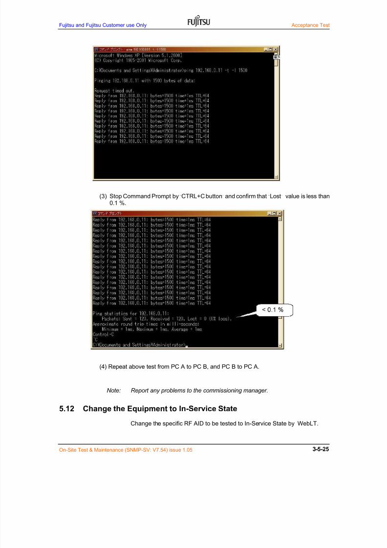
7/24/2019 Frx-3e Test v7.55 Issue1.06 June2014
http://slidepdf.com/reader/full/frx-3e-test-v755-issue106-june2014 117/214
Fujitsu and Fujitsu Customer use Only Acceptance Test
On-Site Test & Maintenance (SNMP-SV: V7.54) issue 1.05
(3) Stop Command Prompt by “CTRL+C button” and confirm that “Lost” value is less than0.1 %.
(4) Repeat above test from PC A to PC B, and PC B to PC A.
Note: Report any problems to the commissioning manager.
5.12 Change the Equipment to In-Service State
Change the specific RF AID to be tested to In-Service State by WebLT.
7/24/2019 Frx-3e Test v7.55 Issue1.06 June2014
http://slidepdf.com/reader/full/frx-3e-test-v755-issue106-june2014 118/214
Acceptance Test Fujitsu and Fujitsu Customer Use Only
On-Site Test & Maintenance (SNMP-SV: V7.54) issue 1.05
This page intent ional ly left blank

7/24/2019 Frx-3e Test v7.55 Issue1.06 June2014
http://slidepdf.com/reader/full/frx-3e-test-v755-issue106-june2014 119/214
Fujitsu and Fujitsu Customer Use Only Acceptance Test
On-Site Test & Maintenance (SNMP-SV: V7.54) issue 1.05
6 Section Tests
This section provides instructions for end-to-end section tests for the FRX radio.This test is carried out for all sections, that is, all Multiplexing Terminal-to- Multiplexing Terminals links.
Note*: Multiplexing terminal is terminal with STM-1 add/drop facility.
Station A and U: Terminal station with STM-1 add/drop facility
Station B to T: Terminal/Repeater station without STM-1 add/drop facility
6.1 RUC Transmission Test
This procedure is to confirm the normal operation of Radio User Channel
(RUC) transmission in accordance with SYSTEM HANDBOOK provided bythe Contractor.
6.1.1 Equipment Required
64 kbit/s BER Measurement Setup
6.1.2 Specifications
Transmission network: In accordance with System Handbook
BER performance: Error free
6.1.3 Test Procedure
1. Confirm that the RUC network is in accordance with the SystemHandbook provided by the Contractor.
2. Measure the end-to-end BER performance for 24 hours and confirm thatBER performance result is error free (no error).
3. BER performance Measurement will be made for Go and Return channelfor all UC/RUC end-to-end channels.
Note: Report any problems to the commissioning manager.
A B C S T Ua on am
Station Tests
Hop Tests
ection Test
Radio Route
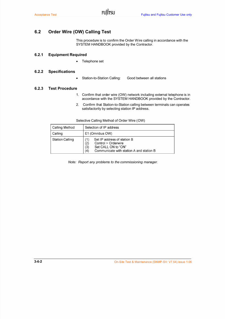
7/24/2019 Frx-3e Test v7.55 Issue1.06 June2014
http://slidepdf.com/reader/full/frx-3e-test-v755-issue106-june2014 120/214
Acceptance Test Fujitsu and Fujitsu Customer Use only
On-Site Test & Maintenance (SNMP-SV: V7.54) issue 1.05
6.2 Order Wire (OW) Calling Test
This procedure is to confirm the Order Wire calling in accordance with theSYSTEM HANDBOOK provided by the Contractor.
6.2.1 Equipment Required
Telephone set
6.2.2 Specifications
Station-to-Station Calling: Good between all stations
6.2.3 Test Procedure
1. Confirm that order wire (OW) network including external telephone is inaccordance with the SYSTEM HANDBOOK provided by the Contractor.
2. Confirm that Station-to-Station calling between terminals can operatessatisfactorily by selecting station IP address.
Selective Calling Method of Order Wire (OW)
Note: Report any problems to the commissioning manager.
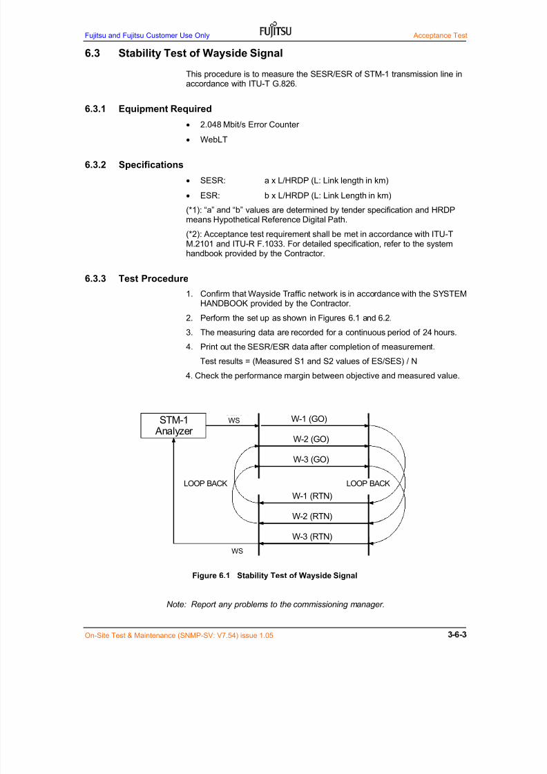
7/24/2019 Frx-3e Test v7.55 Issue1.06 June2014
http://slidepdf.com/reader/full/frx-3e-test-v755-issue106-june2014 121/214
Fujitsu and Fujitsu Customer Use Only Acceptance Test
On-Site Test & Maintenance (SNMP-SV: V7.54) issue 1.05
6.3 Stability Test of Wayside Signal
This procedure is to measure the SESR/ESR of STM-1 transmission line inaccordance with ITU-T G.826.
6.3.1 Equipment Required
2.048 Mbit/s Error Counter
WebLT
6.3.2 Specifications
SESR: a x L/HRDP (L: Link length in km)
ESR: b x L/HRDP (L: Link Length in km)
(*1): “a” and “b” values are determined by tender specification and HRDPmeans Hypothetical Reference Digital Path.
(*2): Acceptance test requirement shall be met in accordance with ITU-TM.2101 and ITU-R F.1033. For detailed specification, refer to the systemhandbook provided by the Contractor.
6.3.3 Test Procedure
1. Confirm that Wayside Traffic network is in accordance with the SYSTEMHANDBOOK provided by the Contractor.
2. Perform the set up as shown in Figures 6.1 and 6.2.
3. The measuring data are recorded for a continuous period of 24 hours.
4. Print out the SESR/ESR data after completion of measurement.
Test results = (Measured S1 and S2 values of ES/SES) / N
4. Check the performance margin between objective and measured value.
Figure 6.1 Stability Test of Wayside Signal
Note: Report any problems to the commissioning manager.
STM-1 Analyzer
W-2 (GO)
W-3 (GO)
W-2 (RTN)
W-1 (RTN)
STM-1
STM-1
LOOP BACKLOOP BACK
W-1 (GO)
W-3 (RTN)
WS
WS

7/24/2019 Frx-3e Test v7.55 Issue1.06 June2014
http://slidepdf.com/reader/full/frx-3e-test-v755-issue106-june2014 122/214
Acceptance Test Fujitsu and Fujitsu Customer Use only
On-Site Test & Maintenance (SNMP-SV: V7.54) issue 1.05
Figure 6.2 WS Stability Test Setup
SD1 3 5 9 7 5 3 1
SDP 2 4 8 6 4 2 P
RX1 3 5 9 7 5 3 1
RXP 2 4 8 6 4 2 P
TX1 3 5 9 7 5 3 1
TXP 2 4 8 6 4 2 P
L6G, 5+1 11G, 9+1
A
UXINTF
A
UXINTF
ETSI Rack (1,800 mm )
TERM
BBINTF(W3)
BBINTF(W2)
BBINTF(W1)
BBINTF(P)
SVG
ESW
GESW
BBINTF(W9)
BBINTF(W8)
BBINTF(W7)
BBINTF(W6)
BBINTF(W5)
BBINTF(W4)
TRMD
(W2)
TRMD
(W1)
TRM
D(P)
Basic shelf
BBINTF(P)
BBINTF(W1)
BBINTF(W2)
BBINTF(W3)
BBINTF(W4)
BBINTF(W5)
V EN T V EN T V EN T
TRMD
(W5)
TRMD
(W4)
TRMD
(W3)
TRMD
(W4)
TRM
D(P)
TRMD
(W5)
TRMD
(W9)
TRMD
(W8)
TRMD
(W7)
TRMD
(W6)
TRADPT
TRADPT
TRMD
(W1)
TRMD
(W2)
TRMD
(W3)
V EN T V EN T V EN TVENT VENT
TRADPT
TRADPT
TRADPT
TRADPT
TRADPT
TRADPT
Antenna Port (Max. 8)
BEF (x4 m ax.) BEF (x4 max.)
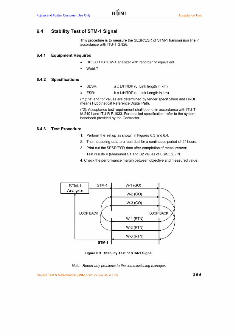
7/24/2019 Frx-3e Test v7.55 Issue1.06 June2014
http://slidepdf.com/reader/full/frx-3e-test-v755-issue106-june2014 123/214
Fujitsu and Fujitsu Customer Use Only Acceptance Test
On-Site Test & Maintenance (SNMP-SV: V7.54) issue 1.05
6.4 Stability Test of STM-1 Signal
This procedure is to measure the SESR/ESR of STM-1 transmission line inaccordance with ITU-T G.826.
6.4.1 Equipment Required
HP 37717B STM-1 analyzer with recorder or equivalent
WebLT
6.4.2 Specifications
SESR: a x L/HRDP (L: Link length in km)
ESR: b x L/HRDP (L: Link Length in km)
(*1): “a” and “b” values are determined by tender specification and HRDPmeans Hypothetical Reference Digital Path.
(*2): Acceptance test requirement shall be met in accordance with ITU-TM.2101 and ITU-R F.1033. For detailed specification, refer to the systemhandbook provided by the Contractor.
6.4.3 Test Procedure
1. Perform the set up as shown in Figures 6.3 and 6.4.
2. The measuring data are recorded for a continuous period of 24 hours.
3. Print out the SESR/ESR data after completion of measurement.
Test results = (Measured S1 and S2 values of ES/SES) / N
4. Check the performance margin between objective and measured value.
Figure 6.3 Stability Test of STM-1 Signal
Note: Report any problems to the commissioning manager.
STM-1 Analyzer
W-2 (GO)
W-3 (GO)
W-2 (RTN)
W-1 (RTN)
STM-1
STM-1
LOOP BACKLOOP BACK
W-1 (GO)
W-3 (RTN)
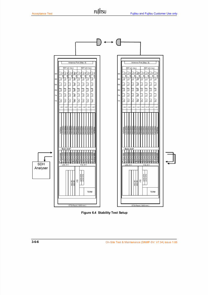
7/24/2019 Frx-3e Test v7.55 Issue1.06 June2014
http://slidepdf.com/reader/full/frx-3e-test-v755-issue106-june2014 124/214
Acceptance Test Fujitsu and Fujitsu Customer Use only
On-Site Test & Maintenance (SNMP-SV: V7.54) issue 1.05
Figure 6.4 Stability Test Setup
SD1 3 5 9 7 5 3 1
SDP 2 4 8 6 4 2 P
RX1 3 5 9 7 5 3 1
RXP 2 4 8 6 4 2 P
TX1 3 5 9 7 5 3 1
TXP 2 4 8 6 4 2 P
L6G, 5+1 11G, 9+1
AUX
INTF
AUX
INTF
ETSI Rack (1,800 mm )
TERM
BBINTF(W3)
BBINTF(W2)
BBINTF(W1)
BBINTF(P)
SVG
ESW
GESW
BBINTF(W9)
BBINTF(W8)
BBINTF(W7)
BBINTF(W6)
BBINTF(W5)
BBINTF(W4)
TRMD(W
2)
TRMD(W
1)
TRMD(P)
Basic shelf
BBINTF(P)
BBINTF(W1)
BBINTF(W2)
BBINTF(W3)
BBINTF(W4)
BBINTF(W5)
V EN T V EN T V EN T
TRMD(W
5)
TRMD(W
4)
TRMD(W
3)
TRMD(W
4)
TRMD(P
)
TRMD(W
5)
TRMD(W
9)
TRMD(W
8)
TRMD(W
7)
TRMD(W
6)
TRADPT
TRADPT
TRMD(W
1)
TRMD(W
2)
TRMD(W
3)
V EN T V EN T V EN TVENT VENT
TRADPT
TRADPT
TRADPT
TRADPT
TRADPT
TRADPT
Antenna Port (Max. 8)
BEF (x4 max.) BEF (x4 m ax.)
SD1 3 5 9 7 5 3 1
SDP 2 4 8 6 4 2 P
RX1 3 5 9 7 5 3 1
RXP 2 4 8 6 4 2 P
TX1 3 5 9 7 5 3 1
TXP 2 4 8 6 4 2 P
L6G, 5+1 11G, 9+1
AUX
INTF
AUX
INTF
ETSI Rack (1,800 mm )
TERM
BBINTF(W3)
BBINTF(W2)
BBINTF(W1)
BBINTF(P)
SVG
ESW
GESW
BBINTF(W9)
BBINTF(W8)
BBINTF(W7)
BBINTF(W6)
BBINTF(W5)
BBINTF(W4)
TRMD(W
2)
TRMD(W
1)
TRMD(P)
Basic shelf
BBINTF(P)
BBINTF(W1)
BBINTF(W2)
BBINTF(W3)
BBINTF(W4)
BBINTF(W5)
V EN T V EN T V EN T
TRMD(W
5)
TRMD(W
4)
TRMD(W
3)
TRMD(W
4)
TRMD(P
)
TRMD(W
5)
TRMD(W
9)
TRMD(W
8)
TRMD(W
7)
TRMD(W
6)
TRADPT
TRADPT
TRMD(W
1)
TRMD(W
2)
TRMD(W
3)
VE NT VE NT V EN TVENT VENT
TRADPT
TRADPT
TRADPT
TRADPT
TRADPT
TRADPT
Antenna Port (Max. 8)
BEF (x4 max.) BEF (x4 m ax.)

7/24/2019 Frx-3e Test v7.55 Issue1.06 June2014
http://slidepdf.com/reader/full/frx-3e-test-v755-issue106-june2014 125/214
Fujitsu and Fujitsu Customer Use Only Acceptance Test
On-Site Test & Maintenance (SNMP-SV: V7.54) issue 1.05
6.5 Gigabit Ethernet Transmission Test
This transmission test is carried out when Gigabit Ethernet for NxSTM1transmission (Link Aggregation) is introduced when GE SW1/2/3 is used.
6.5.1 Equipment Required
Personal computer: 2 sets
Gigabit Ethernet LAN card: 2 sets for 1000BASE-T
ExPing software
Switching HUB: 2 sets for 1000BASE-SX/LX
6.5.2 Specifications
Packet communication loss < 0.1 %
6.5.3 Test setup
(1) In case of GE SW2/3 (1000BASE-SX/LX) interface, switching HUB,expansion module for 1000BASE-SX or 1000BASE-LX and fiber cable withLC duplex connectors both ends are necessary.
(2) In case of GE SW1 (1000BASE-T) interface, LAN card for 1000BASE-T isneeded. And also LAN cable loopback between GE SW1 units is carried out.LAN cable used is UTP category 6 type cable.
6.5.4 Test ProcedureSchematic Gigabit Ethernet test setup is shown below.
(1) Set network setting on WebLT (PC A and PC B)
IP address: 192.168.0.xxx (xxx is excluded 0 or 10)
Sub net mask: 255.255.255.0
Default gateway: 192.168.0.1
(2) Do the Ping communication test using COMMAND PROMPT
Start button >> All program >> Accessary >> Command prompt
Command input: Ping 192.168.0.11 –t –l 1500
Program starts and “Reply from 192.168.0.11: bytes=1500 time=1ms TTL=64” display appears frequently.
GESW GESW
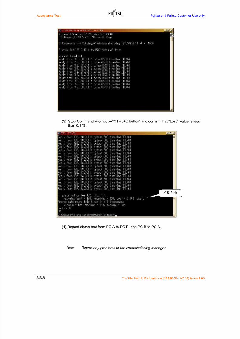
7/24/2019 Frx-3e Test v7.55 Issue1.06 June2014
http://slidepdf.com/reader/full/frx-3e-test-v755-issue106-june2014 126/214
Acceptance Test Fujitsu and Fujitsu Customer Use only
On-Site Test & Maintenance (SNMP-SV: V7.54) issue 1.05
(3) Stop Command Prompt by “CTRL+C button” and confirm that “Lost” value is lessthan 0.1 %.
(4) Repeat above test from PC A to PC B, and PC B to PC A.
Note: Report any problems to the commissioning manager.
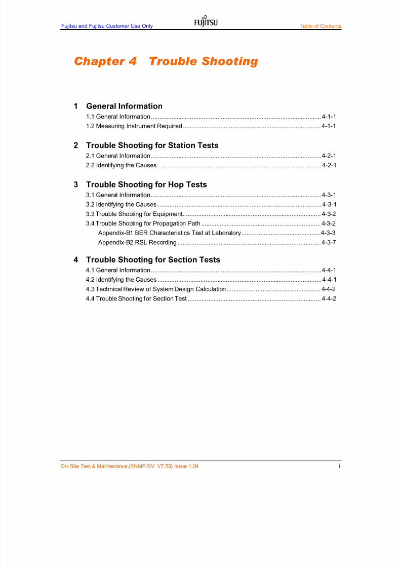
7/24/2019 Frx-3e Test v7.55 Issue1.06 June2014
http://slidepdf.com/reader/full/frx-3e-test-v755-issue106-june2014 127/214
Fujitsu and Fujitsu Customer Use Only Table of Contents
Chapter 4 Trouble Shooting
1 General Information
1.1 General Information .................................................................................................... 4-1-1
1.2 Measuring Instrument Required ................................................................................. 4-1-1
2 Trouble Shooting for Station Tests
2.1 General Information .................................................................................................... 4-2-1
2.2 Identifying the Causes .............................................................................................. 4-2-1
3 Trouble Shooting for Hop Tests
3.1 General Information .................................................................................................... 4-3-1
3.2 Identifying the Causes ................................................................................................ 4-3-1
3.3 Trouble Shooting for Equipment................................................................................. 4-3-2
3.4 Trouble Shooting for Propagation Path ...................................................................... 4-3-2
Appendix-B1 BER Characteristics Test at Laboratory .............................................. 4-3-3
Appendix-B2 RSL Recording .................................................................................... 4-3-7
4 Trouble Shooting for Section Tests4.1 General Information .................................................................................................... 4-4-1
4.2 Identifying the Causes ................................................................................................ 4-4-1
4.3 Technical Review of System Design Calculation ....................................................... 4-4-2
4.4 Trouble Shooting for Section Test .............................................................................. 4-4-2

7/24/2019 Frx-3e Test v7.55 Issue1.06 June2014
http://slidepdf.com/reader/full/frx-3e-test-v755-issue106-june2014 128/214
Table of Contents Fujitsu and Fujitsu Customer Use Only
On-Site Test & Maintenance (SNMP-SV: V7.53) issue 1.04
This page intent ional ly left blank

7/24/2019 Frx-3e Test v7.55 Issue1.06 June2014
http://slidepdf.com/reader/full/frx-3e-test-v755-issue106-june2014 129/214
Fujitsu and Fujitsu Customer Use Only
On-Site Test & Maintenance (SNMP-SV: V7.53) Issue 1.04
1 General Information
1.1 General Information
This section describes how to proceed the trouble shooting when station, hopand section test was carried out and some test items was out of specification.Trouble shooting verifies the following;--
Proper test equipment has been provided.
Test equipment is properly calibrated
Proper test and test procedure has been provided.
Proper propagation condition analysis has been provided.
Other interference factors are well analyzed.
Equipment shelves are free of defects or damages.
The trouble shooting generally assume;--
Accurate and concise system designations and office records areavailable to properly identify systems and equipment.
Any faults found and not corrected during installation & commissioningare referred to the installation & commissioning group responsibility.
1.2 Measuring Instrument Required
Typical test equipment is listed below;
RF power meter
Spectrum analyzer
RF Variable & fixed attenuator (10 W type)
Miscellaneous RF/IF cables and accessories
STM-1 transmission analyzer
Variable optical attenuator with LC Duplex connectors*1
Optical power meter with LC connectors
Optical fiber patch cords with LC connectors
Frequency counter (< 30 MHz)
Multi-meter
PC for WebLT (Local terminal)

7/24/2019 Frx-3e Test v7.55 Issue1.06 June2014
http://slidepdf.com/reader/full/frx-3e-test-v755-issue106-june2014 130/214
Fujitsu and Fujitsu Customer Use Only
On-Site Test & Maintenance (SNMP-SV: V7.53) Issue 1.04
2 Trouble Shooting for Station Tests
2.1 General Information
This section describes how to proceed the trouble shooting and actions duringstation test period. Trouble shooting verifies the following;--
Proper test equipment has been provided.
Test equipment is properly calibrated.
Proper test and test results has been provided.
Proper take action has been carried out.
2.2 Identifying the Causes
Table 2.2 shows the list of identifying- the-Causes.
Table 2.2 Trouble Shooting for Station Test
Task NameManual Reference
in Chapter 3Main Trouble Shooting Method
Station Tests
Hardware Settings Section 4.1 Checking hardware setting
Provisioning (Software Settings) Section 4.2 Checking provisioning settingTransmit Local OSC Frequency Section 4.3 TRMD replacement
Transmit Output Power Level Section 4.4 TRMD replacement
Transmit Spectrum Section 4.5 TRMD replacement
Rack Alarm Tests Section 4.7 SV unit replacement

7/24/2019 Frx-3e Test v7.55 Issue1.06 June2014
http://slidepdf.com/reader/full/frx-3e-test-v755-issue106-june2014 131/214
Fujitsu and Fujitsu Customer Use Only Trouble Shooting
On-Site Test & Maintenance (SNMP-SV: V7.54) Issue 1.05 4-3-1
3 Trouble Shooting for Hop Tests
3.1 General InformationThis section describes how to proceed the trouble shooting and actions during
station test period. Trouble shooting verifies the following;--
Proper test equipment has been provided.
Test equipment is properly calibrated.
Proper test and test results has been provided.
Proper take action has been carried out.
3.2 Identifying the Causes
Table 3.2 shows the list of identifying- the-Causes.
Table 3.2 Trouble Shooting for Hop Test
Hop Tests ItemTest Item
in Chapter 3Main Trouble Shooting Action
Receive Signal Level Section 5.2 System parameter, Antenna re-alignment
Delay Equalizer Select Section 5.3
Auto IF-IF response adjustment Section 5.4 TRMD replacement, antenna feeder
Auto SD DADE Adjustment Section 5.5 Feeder length difference OK?
Auto XPIC DADE Adjustment Section 5.6 Feeder length difference OK?
Auto RPS DADE Adjustment Section 5.7
Radio Protection Switch Test Section 5.8 (1) Correct RPS BB DADE OK?
(2) Correct RPS procedure on LT(3) SV unit replacement
Stability Test of STM-1 Signal Section 5.9 (1) Breakup of equipment and
propagation path(2) Equipment
TRMD/BB INTF replacement
(3) System design parametersFading monitoring, Other system
Interference, RaderGigabit Ethernet Transmission Test Section 5.10 (1) Breakup of equipment
(2) EquipmentTRMD/GESW/GE ADPT replacement
(3) GESW software mis-setting
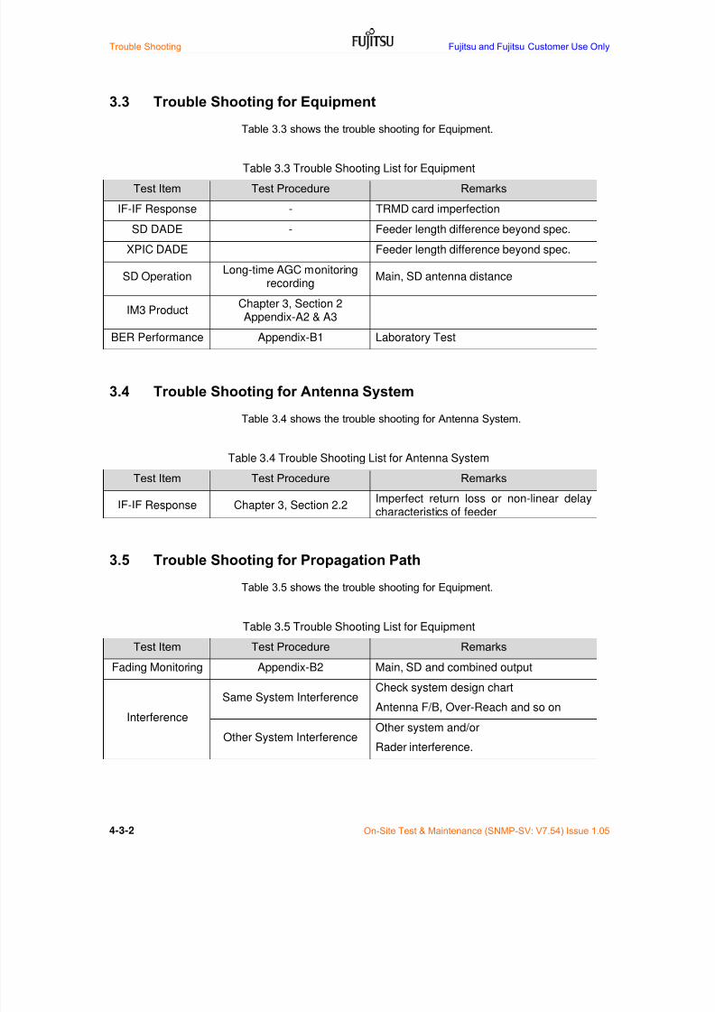
7/24/2019 Frx-3e Test v7.55 Issue1.06 June2014
http://slidepdf.com/reader/full/frx-3e-test-v755-issue106-june2014 132/214
Trouble Shooting Fujitsu and Fujitsu Customer Use Only
4-3-2 On-Site Test & Maintenance (SNMP-SV: V7.54) Issue 1.05
3.3 Trouble Shooting for Equipment
Table 3.3 shows the trouble shooting for Equipment.
Table 3.3 Trouble Shooting List for Equipment
Test Item Test Procedure Remarks
IF-IF Response - TRMD card imperfection
SD DADE - Feeder length difference beyond spec.
XPIC DADE Feeder length difference beyond spec.
SD OperationLong-time AGC monitoring
recordingMain, SD antenna distance
IM3 Product Chapter 3, Section 2Appendix-A2 & A3
BER Performance Appendix-B1 Laboratory Test
3.4 Trouble Shooting for Antenna System
Table 3.4 shows the trouble shooting for Antenna System.
Table 3.4 Trouble Shooting List for Antenna SystemTest Item Test Procedure Remarks
IF-IF Response Chapter 3, Section 2.2Imperfect return loss or non-linear delaycharacteristics of feeder
3.5 Trouble Shooting for Propagation Path
Table 3.5 shows the trouble shooting for Equipment.
Table 3.5 Trouble Shooting List for Equipment
Test Item Test Procedure Remarks
Fading Monitoring Appendix-B2 Main, SD and combined output
Interference
Same System InterferenceCheck system design chart
Antenna F/B, Over-Reach and so on
Other System InterferenceOther system and/or
Rader interference.

7/24/2019 Frx-3e Test v7.55 Issue1.06 June2014
http://slidepdf.com/reader/full/frx-3e-test-v755-issue106-june2014 133/214
Fujitsu and Fujitsu Customer Use Only Trouble Shooting
On-Site Test & Maintenance (SNMP-SV: V7.54) Issue 1.05 4-3-3
Appendix-B1 BER Characteristics Test for STM-1 interface
This BER characteristics test is performed as laboratory test.
B1.1 Equipment Required
MP1550A SDH Analyzer or equivalent.
TRMD test adaptor
30 dB fixed and variable (step) RF attenuator (70 dB)
WebLT
B1-1.2 Specifications
Up fade: BER = 10-10 or better at RSL of –
19 dBm
Down fade: In accordance with Figure B1-2.
B1-1.3 Test Procedure
1. Configure the artificial transmission path as per Figure B1-1.
2. Set all TRMDs to power ON.
3. Set Maintenance State of GP1-W1 to MT-IS.
4. Calibrate received signal level (RSL) of specific RF channel at TRMD RXinput port in accordance with Chapter 3 Acceptance Test, Section 5.2RSL Test and adjust to -40 dBm.
5. Measure the RSL vs. BER performance characteristics by adjusting RFvariable attenuator.
6. Measurement is carried out both up-fade and down fade conditions.
7. Restore Maintenance state to IS (In-Service).
8. Confirm that GP1-W1 of Maintenance State is changed to IS.
9. Repeat item 3 through item 8 for all working RF channels.
Note: Report any problems to the installation group.

7/24/2019 Frx-3e Test v7.55 Issue1.06 June2014
http://slidepdf.com/reader/full/frx-3e-test-v755-issue106-june2014 134/214
Trouble Shooting Fujitsu and Fujitsu Customer Use Only
4-3-4 On-Site Test & Maintenance (SNMP-SV: V7.54) Issue 1.05
Figure B1-1 BER Test Set up
RF variableAttenuator
SDHAnalyser SDHAnalyser
SDHAnalyser
SD1 3 5 9 7 5 3 1
SDP 2 4 8 6 4 2 P
RX1 3 5 9 7 5 3 1
RXP 2 4 8 6 4 2 P
TX1 3 5 9 7 5 3 1
TXP 2 4 8 6 4 2 P
L6G, 5+1 11G, 9+1
A
UXINTF
A
UXINTF
ETSI Rack (1,800 mm)
TERM
BBINTF(W3)
BBINTF(W2)
BBINTF(W1)
BBINTF(P)
SVG
ESW
GESW
BBINTF(W9)
BBINTF(W8)
BBINTF(W7)
BBINTF(W6)
BBINTF(W5)
BBINTF(W4)
TRMD(W2)
TRMD(W1)
TR
MD(P)
Basic shelf
BBINTF(P)
BBINTF(W1)
BBINTF(W2)
BBINTF(W3)
BBINTF(W4)
BBINTF(W5)
V EN T VE NT VE NT
TRMD(W5)
TRMD(W4)
TRMD(W3)
TRM
D(W4)
TR
MD(P)
TRM
D(W5)
TRMD(W9)
TRMD(W8)
TRMD(W7)
TRMD(W6)
TRADPT
TRADPT
TRM
D(W1)
TRM
D(W2)
TRM
D(W3)
V EN T V EN T VE NTV ENT V ENT
TRADPT
TRADPT
TRADPT
TRADPT
TRADPT
TRADPT
Antenna Port (Max. 8)
BEF (x4 m ax.) BEF (x4 m ax.)
SD1 3 5 9 7 5 3 1
SDP 2 4 8 6 4 2 P
RX1 3 5 9 7 5 3 1
RXP 2 4 8 6 4 2 P
TX1 3 5 9 7 5 3 1
TXP 2 4 8 6 4 2 P
L6G, 5+1 11G, 9+1
A
UXINTF
A
UXINTF
ETSI Rack (1,800 mm)
TERM
BBINTF(W3)
BBINTF(W2)
BBINTF(W1)
BBINTF(P)
SVG
ESW
GESW
BBINTF(W9)
BBINTF(W8)
BBINTF(W7)
BBINTF(W6)
BBINTF(W5)
BBINTF(W4)
TRMD(W2)
TRMD(W1)
TR
MD(P)
Basic shelf
BBINTF(P)
BBINTF(W1)
BBINTF(W2)
BBINTF(W3)
BBINTF(W4)
BBINTF(W5)
VE NT V EN T V EN T
TRMD(W5)
TRMD(W4)
TRMD(W3)
TRM
D(W4)
TR
MD(P)
TRM
D(W5)
TRMD(W9)
TRMD(W8)
TRMD(W7)
TRMD(W6)
TRADPT
TRADPT
TRM
D(W1)
TRM
D(W2)
TRM
D(W3)
VE NT VEN T V EN TV ENT V ENT
TRADPT
TRADPT
TRADPT
TRADPT
TRADPT
TRADPT
Antenna Port (Max. 8)
BEF (x4 m ax.) BEF (x4 m ax.)

7/24/2019 Frx-3e Test v7.55 Issue1.06 June2014
http://slidepdf.com/reader/full/frx-3e-test-v755-issue106-june2014 135/214
Fujitsu and Fujitsu Customer Use Only Trouble Shooting
On-Site Test & Maintenance (SNMP-SV: V7.54) Issue 1.05 4-3-5
(a) Down Fade BER Characteristics for 64 QAM system
ETSI limit at Point B (*)
-67.5 dBm/BER=10E-6
ETSI limit at Point B (*)
-63.5 dBm/BER=10E-10
BER - RSL Performance (64QAM, STM1, 40 MHz CS)
-72.5/10E-6
Receiver Signal Level (RSL) at TRMD Unit Input (at Point A)
-74 -72 -70 -68 -66 -64 -62
10E-9
10E-10
10E-11
10E-12
10E-3
10E-4
10E-5
10E-6
B i t E r r o r R a t i o ( B E R )
Typical BER
BER specification
-70.5/10E-10
-76
Note*: Calibration value
at Point A and Point B isshown in Table 5-1.
10E-7
10E-8

7/24/2019 Frx-3e Test v7.55 Issue1.06 June2014
http://slidepdf.com/reader/full/frx-3e-test-v755-issue106-june2014 136/214

7/24/2019 Frx-3e Test v7.55 Issue1.06 June2014
http://slidepdf.com/reader/full/frx-3e-test-v755-issue106-june2014 137/214
Fujitsu and Fujitsu Customer Use Only Trouble Shooting
On-Site Test & Maintenance (SNMP-SV: V7.54) Issue 1.05 4-3-7
Appendix-B2 RSL Recording
B2.1 AGC Current Monitoring
AGC current of all RF channels (PRT and Working CHs) both Main and SDreceivers can be monitored through the XPIC connector CNxx on TRMD asshown in Figure B2.1.
Figure B2.1 Multi-pin connector layout on TRMD card
XPICConnector
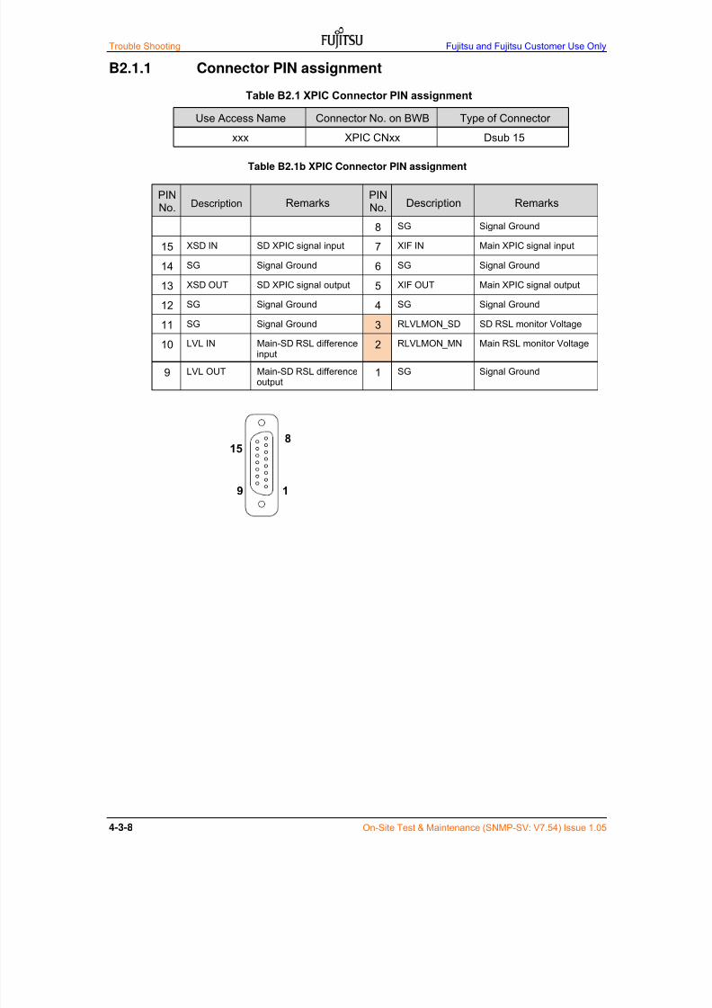
7/24/2019 Frx-3e Test v7.55 Issue1.06 June2014
http://slidepdf.com/reader/full/frx-3e-test-v755-issue106-june2014 138/214
Trouble Shooting Fujitsu and Fujitsu Customer Use Only
4-3-8 On-Site Test & Maintenance (SNMP-SV: V7.54) Issue 1.05
B2.1.1 Connector PIN assignment
Table B2.1 XPIC Connector PIN assignment
Use Access Name Connector No. on BWB Type of Connector
xxx XPIC CNxx Dsub 15
Table B2.1b XPIC Connector PIN assignment
PINNo. Description Remarks
PINNo. Description Remarks
8 SG Signal Ground
15 XSD IN SD XPIC signal input 7 XIF IN Main XPIC signal input
14 SG Signal Ground 6 SG Signal Ground
13 XSD OUT SD XPIC signal output 5 XIF OUT Main XPIC signal output
12 SG Signal Ground 4 SG Signal Ground
11 SG Signal Ground 3 RLVLMON_SD SD RSL monitor Voltage
10 LVL IN Main-SD RSL differenceinput
2 RLVLMON_MN Main RSL monitor Voltage
9 LVL OUT Main-SD RSL differenceoutput
1 SG Signal Ground
9 1
15
8

7/24/2019 Frx-3e Test v7.55 Issue1.06 June2014
http://slidepdf.com/reader/full/frx-3e-test-v755-issue106-june2014 139/214
Fujitsu and Fujitsu Customer Use Only
On-Site Test & Maintenance (SNMP-SV: V7.53) Issue 1.04
4 Trouble Shooting for Section Test
4.1 General Information
This section describes how to proceed the trouble shooting and actions duringsection test period. Trouble shooting verifies the following;--
Proper test equipment has been provided.
Test equipment is properly calibrated.
Proper test and test results has been provided.
Proper take action has been carried out.
4.2 Identifying the Causes
Table 4.1 shows the list of identifying- the-Causes.
Table 4.1 Trouble Shooting for Section Test
Section Tests ItemTest Item inChapter 3
Main Trouble Shooting Action
UC/RUC Test Section 6.1 Checking UC/RUC connection
Order Wire (OW) Test Section 6.2 Checking OW connection
Stability Test of Wayside Signal Section 6.3 Technical review of System Design Calculation
Stability Test of STM-1 Signal Section 6.4 Technical review of System Design CalculationGigabit Ethernet Transmission Section 6.5 Checking L2SW software setting

7/24/2019 Frx-3e Test v7.55 Issue1.06 June2014
http://slidepdf.com/reader/full/frx-3e-test-v755-issue106-june2014 140/214
Trouble Shooting Fujitsu and Fujitsu Customer Use Only
On-Site Test & Maintenance (SNMP-SV: V7.53) Issue 1.04
4.3 Technical Review of System Design Calculation
Table 4.2 shows the technical review of System Design Calculation.
Item Test Procedure Remarks
4.4 Trouble Shooting for Section Test
Table 4.3 shows the trouble shooting actions.
Item Test Procedure Remarks

7/24/2019 Frx-3e Test v7.55 Issue1.06 June2014
http://slidepdf.com/reader/full/frx-3e-test-v755-issue106-june2014 141/214
Chapter 5 Routine Maintenance
1 Maintenance Philosophy1.1 Maintenance Philosophy 5-1-1
1.2 Human Machine Interface 5-1-1
2 Alarm Monitoring & Database Download2.1 Condition Monitoring 5-2-1
2.2 RPS Condition Monitoring 5-2-4
2.3 RPS History Monitoring 5-2-5
2.4 Performance Monitoring 5-2-6
2.5 Analog Monitor 5-2-7
2.6 Database Download 5.2.8
3 Other Monitoring Function
3.1 Loop Back 5-3-1 3.2 LED Indication on SV 5-3-2
3.3 LED Indication on Other Card 5-3-4
3.4 Rack Alarm Bus (RAB) Indication 5-3-5
4 Unit & Card Replacement
4.1 Caution for Card Replacement 5-4-1 4.2 Ventilator Replacement 5-4-2
4.3 TRMD and Other Unit & Card 5-4-2 4.4 SV Card Replacement 5-4-3
4.5 Returning Replaced Cards 5-4-5
7/24/2019 Frx-3e Test v7.55 Issue1.06 June2014
http://slidepdf.com/reader/full/frx-3e-test-v755-issue106-june2014 142/214
This page intent ional ly left blank
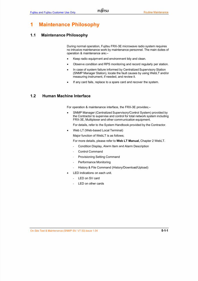
7/24/2019 Frx-3e Test v7.55 Issue1.06 June2014
http://slidepdf.com/reader/full/frx-3e-test-v755-issue106-june2014 143/214
Fujitsu and Fujitsu Customer Use Only
On-Site Test & Maintenance (SNMP-SV: V7.53) issue 1.04
1 Maintenance Philosophy
1.1 Maintenance Philosophy
During normal operation, Fujitsu FRX-3E microwave radio system requiresno intrusive maintenance work by maintenance personnel. The main duties ofoperation & maintenance are;--
Keep radio equipment and environment tidy and clean.
Observe condition and RPS monitoring and record regularly per station.
In case of system failure informed by Centralized Supervisory Station(SNMP Manager Station), locate the fault causes by using WebLT and/ormeasuring instrument, if needed, and review it.
If any card fails, replace to a spare card and recover the system.
1.2 Human Machine Interface
For operation & maintenance interface, the FRX-3E provides;--
SNMP Manager (Centralized Supervisory/Control System) provided bythe Contractor to supervise and control for total network system includingFRX-3E, Multiplexer and other communication equipment.
For details, refer to the System Handbook provided by the Contractor.
Web LT (Web-based Local Terminal)
Major function of WebLT is as follows;
For more details, please refer to Web LT Manual, Chapter 2 WebLT.
- Condition Display, Alarm Item and Alarm Description
- Control Command
- Provisioning Setting Command
- Performance Monitoring
- History & File Command (History/Download/Upload)
LED indications on each unit.
- LED on SV card
- LED on other cards

7/24/2019 Frx-3e Test v7.55 Issue1.06 June2014
http://slidepdf.com/reader/full/frx-3e-test-v755-issue106-june2014 144/214
Routine Maintenance Fujitsu and Fujitsu Customer Use Only
On-Site test & Maintenance (SNMP-SV: V7.53) Issue 1.04
Rack Alarm Bus (RAB) to extend alarm/status information to externalcommunication equipment is as follows. For details, please refer toSection 3.4.
- NE Alarm (*1)
- Alarm Cut Off (*1)
- Audio Critical Alarm
- Visual Critical Alarm
- Audio Major Alarm
- Visual Major Alarm
- Audio Minor Alarm
- Visual Minor Alarm
- Audio Warning
- Visual Warning
- Maintenance
Note-*1: When RAB module is not installed on SV card, only NE Alarm
and Alarm Cut OFF are available.

7/24/2019 Frx-3e Test v7.55 Issue1.06 June2014
http://slidepdf.com/reader/full/frx-3e-test-v755-issue106-june2014 145/214
Monitoring
On-Site Test & Maintenance (SNMP-SV: V7.53) Issue 1.04
2 Condition Monitoring & Database Download
Regular condition monitoring items for routine maintenance and database storage ofprovisioning setting data are described below;
2.1 Condition Monitoring
Condition > Display
Confirm that all slot cards are displayed in green and no alarm indicationappears.
Menu: Condition > Display
When alarm appears, click Condition < TRMD/BBINTF/COM to itemizethe detailed alarm item and description.
In case of CR (Critical Alarm) and MJ (Major Alarm), quick action shouldbe necessary. And for MN (Minor Alarm), WR (Warning) and MAINT(Maintenance), access to information is needed.

7/24/2019 Frx-3e Test v7.55 Issue1.06 June2014
http://slidepdf.com/reader/full/frx-3e-test-v755-issue106-june2014 146/214
Monitoring Fujitsu and Fujitsu Customer Use Only
On-Site test & Maintenance (SNMP-SV: V7.53) Issue 1.04
Condition > ALL
Confirm that the summarized Alarm Time, AID Type, AID, Item, SA/NSA andSEV form Condition > ALL menu.
Condition > TRMD
Judging alarm item and alarm description, trouble shooting should be
carried out from Condition > TRMD.

7/24/2019 Frx-3e Test v7.55 Issue1.06 June2014
http://slidepdf.com/reader/full/frx-3e-test-v755-issue106-june2014 147/214
Monitoring
On-Site Test & Maintenance (SNMP-SV: V7.53) Issue 1.04
Condition > BB INT
Judging alarm item and alarm description, trouble shooting should becarried out from Condition > BBINTF.
Condition > COM
Judging alarm item and alarm description, trouble shooting should becarried out from Control > COM.
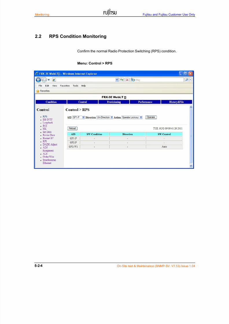
7/24/2019 Frx-3e Test v7.55 Issue1.06 June2014
http://slidepdf.com/reader/full/frx-3e-test-v755-issue106-june2014 148/214
Monitoring Fujitsu and Fujitsu Customer Use Only
On-Site test & Maintenance (SNMP-SV: V7.53) Issue 1.04
2.2 RPS Condition Monitoring
Confirm the normal Radio Protection Switching (RPS) condition.
Menu: Control > RPS
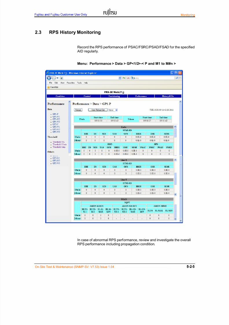
7/24/2019 Frx-3e Test v7.55 Issue1.06 June2014
http://slidepdf.com/reader/full/frx-3e-test-v755-issue106-june2014 149/214
Monitoring
On-Site Test & Maintenance (SNMP-SV: V7.53) Issue 1.04
2.3 RPS History Monitoring
Record the RPS performance of PSAC/FSRC/PSAD/FSAD for the specified AID regularly.
Menu: Performance > Data > GP<1/2>-< P and M1 to M#n >
In case of abnormal RPS performance, review and investigate the overallRPS performance including propagation condition.

7/24/2019 Frx-3e Test v7.55 Issue1.06 June2014
http://slidepdf.com/reader/full/frx-3e-test-v755-issue106-june2014 150/214
Monitoring Fujitsu and Fujitsu Customer Use Only
On-Site test & Maintenance (SNMP-SV: V7.53) Issue 1.04
2.4 Performance Monitoring
Record the Performance Monitoring for all RF channels regularly.
Menu: Performance > Data > GP<1/2>-<P and W1 to W#n>
In case of abnormal performance monitoring, review and investigate theoverall performance including propagation condition.

7/24/2019 Frx-3e Test v7.55 Issue1.06 June2014
http://slidepdf.com/reader/full/frx-3e-test-v755-issue106-june2014 151/214
Monitoring
On-Site Test & Maintenance (SNMP-SV: V7.53) Issue 1.04
2.5 Analog Monitor
Record the Analog Monitor of RL-M/SD and TL for all RF channels regularly.
Menu: Performance > Others > Analog Monitor
This short term RF level monitor is very convenient to recognize the TRMDinput and output signal level.

7/24/2019 Frx-3e Test v7.55 Issue1.06 June2014
http://slidepdf.com/reader/full/frx-3e-test-v755-issue106-june2014 152/214
Monitoring Fujitsu and Fujitsu Customer Use Only
On-Site test & Maintenance (SNMP-SV: V7.53) Issue 1.04
2.6 Database Download
Store the provisioning setting database inside SV card regularly to the PC.This work is very important when SV card replacement is necessary. When
database storage is not made, automatic set-up (provisioning) data downloadis not available.
For detailed database download, please refer to Web-Base LT Manual.
Menu: History&File > Download > Database
(1) Select Database and download for all databases.
Download > Do you want to create file? > Yes > Store Database on PC
(2) Database file should be managed per station for maintenance.

7/24/2019 Frx-3e Test v7.55 Issue1.06 June2014
http://slidepdf.com/reader/full/frx-3e-test-v755-issue106-june2014 153/214
Fujitsu and Fujitsu Customer Use Only Other Monitoring Function
On-Site Test & Maintenance (SNMP-SV: V7.53) Issue 1.04 5-3-1
3 Other Monitoring Functions
3.1 Loop Back
Two (2) types of baseband loopback function are available for maintenancepurposs, line loopback and radio loopback, as shown in Figure 3.1.
For the configuration of both STM-1 electrical and optical interface, the loopback is carried out at the BB INTF card inside.
Loopback test interrupts both uni-directional and bi-directional traffics.For safety of traffic, the loop back operation is guarded by maintenance state.Before carrying out loop back, you should change Service State from IS toMT-IS State for the specific RF CH.
Menu: Provisioning < Service State
(1) Set Set-up Value of specified AID to IS-MT.
(2) Select loopback menu
Menu: Control > Loopback
> Select AID be looped backed CH> Select Line-X/Line-Y/Radio > Operate
Figure 3.1 Loop Back Operation
(3) Release Loopback
After loopback test, release loopback and service state should be IS.
SW
RSPI
RSPI
Radio LoopbackLine Loopback
Pointer
Pointer MS Insert RS Insert
TRMDBB INTF-X/Y
MS Drop RS Drop
RS Drop MS Drop
RS Insert MS Insert

7/24/2019 Frx-3e Test v7.55 Issue1.06 June2014
http://slidepdf.com/reader/full/frx-3e-test-v755-issue106-june2014 154/214
Other Monitoring Function Fujitsu and Fujitsu Customer Use Only
5-3-2 On-Site Test & Maintenance (SNMP-SV: V7.53) Issue 1.04
3.2 LED Indication on SV
The SV (Supervisory) card on COM block indicates the summary ofalarms/status conditions. The LEDs on SV card are visible by removing the
bonnet cover of initial shelf.
Each card has LEDs for local indication of alarm/status summary. The LEDson each card will be observed by removing the bonnet cover.
Figure 3.2 and Table 3.1 show LED indications on SV card.
Figure 3.2 Front View of SV Card
Web LT

7/24/2019 Frx-3e Test v7.55 Issue1.06 June2014
http://slidepdf.com/reader/full/frx-3e-test-v755-issue106-june2014 155/214
Fujitsu and Fujitsu Customer Use Only Other Monitoring Function
On-Site Test & Maintenance (SNMP-SV: V7.53) Issue 1.04 5-3-3
Table 3.1 LED Indication of SV Card
LED Indication
Group LED Color Status Description
IndicationforSV card
UNIT/RCI Red Solid on Unit failure of SV card
Blinking RCI (Remote Card Identifier) of SV card
Green (Y) Solid on Normal operation of SV card
Yellow (G) Blinking Configuration mismatch of SV card
LINE Red Solid on SINT/ RSC/DCC signal failure
Green (Y) Solid on SINT/ RSC/DCC signal normal
MISC Red Solid on Housekeeping alarm (DI) on
ACS/SWDL Green (Y) Blinking Provisisioning/SWDL data is being writing
Red Solid on Mismatch of software version
Indicationfor NE
NORM Green (Y) Solid on Normal operation of NE
NE ALM/RCI
Red Solid on CR/MJ/MN/WR alarm of any unit in NE
Blinking RCI (Remote Card Identifier) of any unit in NE
MAINT Yellow (G) Solid on Maintenance condition of NE
CARD OUT Red Solid on CARD ALM of NE more serious than WR
Yellow (G) Solid on CARD ALM of NE not more serious than WR
ACO Yellow (G) Solid on Alarm cut off of NE
Orderwire CALL E1 Green (Y) Blinking Orderwire is being called
Note : Green (Y)
Yellow (G)
= Green for LED mode 2, Yellow for LED mode 1.
= Yellow for LED mode 2, Green for LED mode 1.
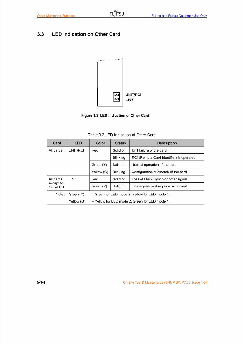
7/24/2019 Frx-3e Test v7.55 Issue1.06 June2014
http://slidepdf.com/reader/full/frx-3e-test-v755-issue106-june2014 156/214
Other Monitoring Function Fujitsu and Fujitsu Customer Use Only
5-3-4 On-Site Test & Maintenance (SNMP-SV: V7.53) Issue 1.04
3.3 LED Indication on Other Card
Table 3.2 LED Indication of Other Card
Card LED Color Status Description
All cards UNIT/RCI Red Solid on Unit failure of the card
Blinking RCI (Remote Card Identifier) is operated
Green (Y) Solid on Normal operation of the card
Yellow (G) Blinking Configuration mismatch of the card
All cardsexcept forGE ADPT
LINE Red Solid on Loss of Main, Synch or other signal
Green (Y) Solid on Line signal (working side) is normal
Note : Green (Y)
Yellow (G)
= Green for LED mode 2, Yellow for LED mode 1.
= Yellow for LED mode 2, Green for LED mode 1.
Figure 3.3 LED Indication of Other Card
UNIT/RCI
LINE

7/24/2019 Frx-3e Test v7.55 Issue1.06 June2014
http://slidepdf.com/reader/full/frx-3e-test-v755-issue106-june2014 157/214
Fujitsu and Fujitsu Customer Use Only Other Monitoring Function
On-Site Test & Maintenance (SNMP-SV: V7.53) Issue 1.04 5-3-5
3.4 Rack Alarm Bus (RAB) Indication
Rack alarm bus (RAB) information can be monitored through the connector CN112 on
the back-wired-board of TRMD shelf as shown in Table 3.3.
Table 3.3-1 Connector PIN assignment for RAB
Use Access Name Connector No. on BWB Type of Connector
RAB UIA-CN112 Dsub 15
Table 3.3-2 Connector PIN assignment for RAB
PINNo. Description Remarks
PINNo. Description Remarks
8 Common
15 RAB-Common RAB Common Ground 7 VIS-MN Visual Minor
14 ACOIN Alarm Cut Off IN 6 AUD-MN Audio Minor
13 NEALM-N NE Alarm N 5 VIS-MJ Visual Major
12 NE-ALM-C NE Alarm C 4 AUD-MJ Audio Major
11 RAB-MNT RAB Maintenance 3 VIS-CR Visual Critical
10 VIS-WR Visual Warning 2 AUD-CR Audio Critical
9 AUD-WR Audio Warning 1 FG Frame Ground
Note: When RAB module is installed on SV card, Pin-1 to Pin-15 are available. If not,only Pin-13 and Pin-15 are available.
9 1
15
8
7/24/2019 Frx-3e Test v7.55 Issue1.06 June2014
http://slidepdf.com/reader/full/frx-3e-test-v755-issue106-june2014 158/214
Other Monitoring Function Fujitsu and Fujitsu Customer Use Only
5-3-6 On-Site Test & Maintenance (SNMP-SV: V7.53) Issue 1.04
This page intent ional ly left blank

7/24/2019 Frx-3e Test v7.55 Issue1.06 June2014
http://slidepdf.com/reader/full/frx-3e-test-v755-issue106-june2014 159/214
Fujitsu and Fujitsu Customer Use Only Routine Maintenance
On-Site Test & Maintenance (SNMP-SV: V7.54) Issue 1.05 5-4-1
4 Card Replacement
CAUTION
Most of card replacement operations affect on the traffictransmission service.
The maintenance staff should inform these operations tothe Central Maintenance & Operation Center (CMOC) inadvance.
4.1 Caution for Card Replacement
Card replacement will be made in accordance with the availability of hot swapand replacement procedure in Table 4.1,
Table 4.1 Card Replacement Procedure and Availability of Hot Swap
Card Hot swap Card Replace Procedure
TRMD Yes (1) Switchover the relevant RF CH to the PRT CH(2) Replace TRMD(3) Switch back the relevant RF CH from PRT CH(4) Card replacement without traffic interruption available
BBINTF
(electrical)
Yes Only in case that 1+1 BB redundant operation is applied,
card replacement without traffic interruption is available.If not, bi-directional traffic interruption is occurred.
BBINTF
(optical)
Yes Only in case that 1+1 BB redundant operation is applied,card replacement without traffic interruption is available.If not, bi-directional traffic interruption is occurred.
STM4O Yes With STM-4 traffic interruption
SV Yes (1) Confirmation of not being ACS/SWDL(2) Replace SV card with default mode(3) Memory set-up value backup from PC.(4) Remove SV and plug-in again with operation mode
AUX INTF Yes With radio user channel traffic interruption
GESW v1 Yes With 1000BASE-T/SX/LX signal interruption
GESW v2 Yes With 1000BASE-T/SX/LX signal interruption
BRSW Yes With bi-directional STM-1 electrical signal interruption

7/24/2019 Frx-3e Test v7.55 Issue1.06 June2014
http://slidepdf.com/reader/full/frx-3e-test-v755-issue106-june2014 160/214
Routine Maintenance Fujitsu and Fujitsu Customer Use Only
5-4-2 On-Site Test & Maintenance (SNMP-SV: V7.54) Issue 1.05
4.2 Ventilator Replacement
VENT unit on TRMD Adaptor is equipped with four air cooling ventilators fortwo TRMD cards. VENT unit should be replaced with spares when VENT
alarm is issued. Table 4.2 shows the relationship of VENT alarm andequipment condition. (MTBF of VENT unit is >80 years and >10 years perrack with 16 systems working condition.)
Table 4.2 VENT Alarm and Equipment Conditions
Number of VENTs Equipment
Working Faulty Alarm Condition for TRMD
4 0 No alarm Normal operation
3 1 VENT Alarm Normal operation
2 2 VENT Alarm High power to Standard power1 3 VENT Alarm
UNIT Failure
TRMD power supply is forcedly OFFand BSW is activated with main trafficinterruption
VENT unit removal
How to replace VENT unit
1. One of two TRMD cards (left side) issuing VENT alarm on TRMDadaptor is Bi-Directional switchovered to the PRT channel.
2. Remove connector on VENT unit (left side)
3. Connect special jig with removed TRMD VENT cable connector.
4. Restore the RPS switching to normal condition.
5. One of two TRMD cards (right side) issuing VENT alarm on TRMDadaptor is Bi-Directional switchovered to the PRT channel.
6. Remove connector on VENT unit (right side)7. Connect special jig with removed TRMD VENT cable connector.
8. Remove VENT unit and replace new VENT unit.
9. TRMD cards (left side) is Bi-Directional switchovered to the PRTchannel and connect VENT cable.
10. Restore the RPS switching to the normal.
11. TRMD cards (right side) is Bi-Directional switchovered to the PRTchannel and connect VENT cable.
12. Restore the RPS switching to the normal.
13. VENT unit replacement is completed.Note: Above procedure is tempolary instruction and VENT replacement commandmenu on WebLT without jig will be released in near future.
PAY ATTENTION
DO NOT REMOVE VENT UNIT except for VENT unit replacement.VENT unit removal induces TRMD power supply OFF and main traffic interruption
7/24/2019 Frx-3e Test v7.55 Issue1.06 June2014
http://slidepdf.com/reader/full/frx-3e-test-v755-issue106-june2014 161/214
Fujitsu and Fujitsu Customer Use Only Routine Maintenance
On-Site Test & Maintenance (SNMP-SV: V7.54) Issue 1.05 5-4-3
4.3 TRMD and Other Unit & Card
TRMD Card
To replace TRMD, the traffic should be switched over to the protection
channel by FORCED operation of RPS in advance.
BB INTF Card
To replace BB INTF-X, the traffic is interrupted. When 1+1 BB redundancyoperation is applied, the traffic of BB INTF-X should be switched over to theBB INTF-Y channel and replacement without traffic interruption is available.
System Set-up Value Data (Provisioning Value)
System set-up data for each card is registered and stored in the SV card.When a card is replaced with spares, the system setting data will betransferred from the SV card automatically. There is no setting change after
card replacement.
System DADE’ing Value Data (Maintenance/Operation Value)
System DADE’ing data for SD DADE, XSD DADE and XPIC DADE for eachRF channel is registered and stored in the SV card. When a TRMD card isreplaced with spares, DADE’ing setting data should be re-adjusted. There isno re-adjustment needed when same TRMD is removed and installed again.
After card replacement;--
Replace card and wait at least 10 minutes to complete the system setting
data downloaded. Check LED indication on FRX-3E equipment.
Check Alarm/Status indication in Alarm & Maintenance/Operation menu.
Check Analog Monitor in Performance menu.
Check the applicable system setting in set-up menu.
Check that Service State is In-Service in set-up menu.
Leave equipment for stability check at least 30 minutes.
Check Error Performance by Current in Performance menu.
Compare the above data with other channels.
Minimize setting change and re-adjustment of the replaced card unlessperformance does not meet the long term specification. If setting changeand readjustment required, follow the instructions of Part 3 “AcceptanceTest ” .
Removal of Miss-removal Protection Metal Plate
Remove the miss-removal protection metal plate located in the upper part ofslide-in-unit shelf on BB INTF block;--
Remove the metal plate by two fixing bolts before unit replacement
Fix the metal plate by two fixing bolts after replacement

7/24/2019 Frx-3e Test v7.55 Issue1.06 June2014
http://slidepdf.com/reader/full/frx-3e-test-v755-issue106-june2014 162/214
Routine Maintenance Fujitsu and Fujitsu Customer Use Only
5-4-4 On-Site Test & Maintenance (SNMP-SV: V7.54) Issue 1.05
4.4 SV Card Replacement
The system setting data (provisioning setting data) is stored in the innermemory on the main PCB on SV card. Therefore the data should beregistered to the spare SV unit when SV card fails.
To replace the SV card with a spare SV card;--
System setting data should be downloaded regularly from working SVcard to the PC (Welt) that is already installed by History&Downloadapplication of WebLT. If not, all provisioning data downloading is notpossible. For detailed downloading, refer to the Web-Based LT Manual.
Check the RPS is in normal condition (no protection switch operation).
Check the ASC/SWDL LED being off (no one access the NE)
Change the Service State of RPS from Enable to Disable.
Set-up > RF Setting > Radio Interface (RSPI)> Select working AIDs
> Enable to Disable for all working CHs> Operate
Remove the failed SV card.
Set switch SW24A-bit7 and SWB1A-bit2 on spare SV card to ON.(default value)
Mount the spare SV card.
Wait a minute for SV card startup.
Set IP address of WebLT to 192.168.0.xx (xx: except 10) and set IPaddress of spare SV card to 192.168.0.10.
System setting data is uploaded WebLT to spare SV card.
History& Download > Upload > Database> Select DB folder on PC> Upload
Set operation IP address to the spare SV unit.
Remove the spare SV unit.
Set switch SW24A-bit7 and SWB1A-bit2 on spare SV unit to OFF.(operation mode)
Set IP address of WebLT to normal state.
Change the Service State of RPS from Disable to Enable.
Set-up > RF Interface > Radio Interface (RPSI)> Select AID for all working CHs
> Disable to Enable> Operate
Check the RPS operations. If the failure of SV unit extended to the RPStotal operation, you must check all functions related.

7/24/2019 Frx-3e Test v7.55 Issue1.06 June2014
http://slidepdf.com/reader/full/frx-3e-test-v755-issue106-june2014 163/214
Fujitsu and Fujitsu Customer Use Only Routine Maintenance
On-Site Test & Maintenance (SNMP-SV: V7.54) Issue 1.05 5-4-5
Figure 4.1 shows the SW24A and SWB1A position
CAUTION
This SV card contains devices that may be damaged byElectrostatic Discharge (ESD).
Observe all precautions relating to the safe handling of ESDsensitive equipment.
Figure 4.1 Switch SW24A and SWB1A position
SW24A
SWB1A

7/24/2019 Frx-3e Test v7.55 Issue1.06 June2014
http://slidepdf.com/reader/full/frx-3e-test-v755-issue106-june2014 164/214
Routine Maintenance Fujitsu and Fujitsu Customer Use Only
5-4-6 On-Site Test & Maintenance (SNMP-SV: V7.54) Issue 1.05
4.5 Returning Replaced Cards
Cards for Fujitsu FRX-3E equipment are manufactured based on high densityintegrated assembling and require special tools, jigs and measurementequipment for repair. Faulty unit should be returned to the manufacturer forrepair.
For quick and adequate repair work, following information is essential to beattached to the unit.
Unit name
Serial No.
Station name
Facing station name
Frequency band
Channel No.
System configuration
Date and time alarm/abnormality detected
Date and time the unit replaced
Detailed description of alarm/abnormality
Alarm/status log of the local station and associated stations
Error performance log of the local station and associated stations
Detailed description after unit replacement
The user can use its own report format.
Table 4.2 shows an example of “Faulty Unit Report”
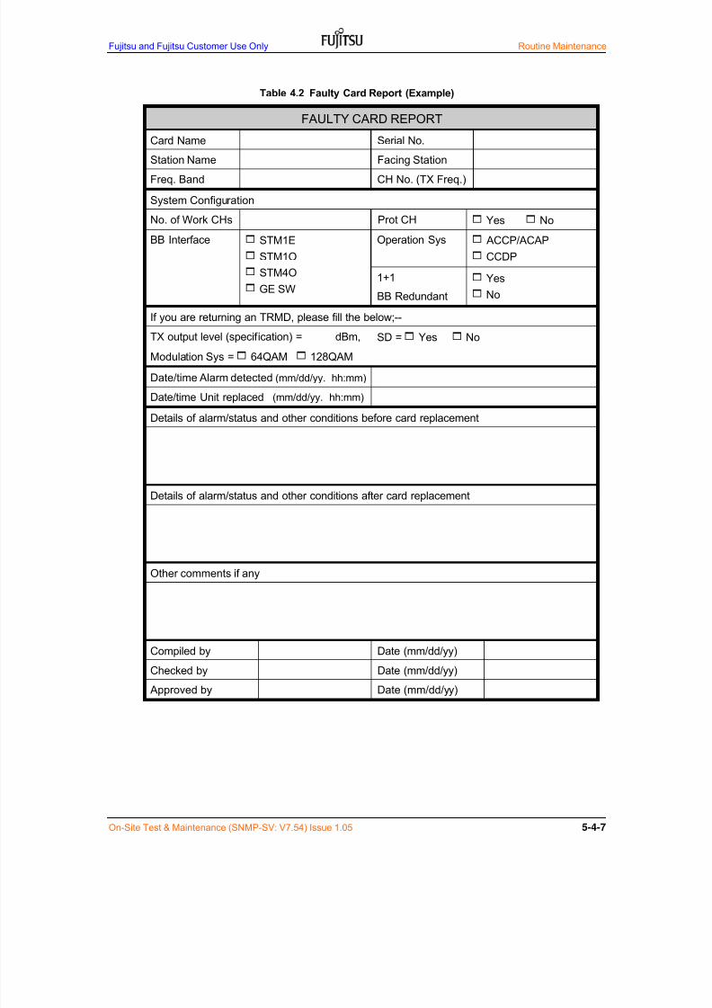
7/24/2019 Frx-3e Test v7.55 Issue1.06 June2014
http://slidepdf.com/reader/full/frx-3e-test-v755-issue106-june2014 165/214
Fujitsu and Fujitsu Customer Use Only Routine Maintenance
On-Site Test & Maintenance (SNMP-SV: V7.54) Issue 1.05 5-4-7
Table 4.2 Faulty Card Report (Example)
FAULTY CARD REPORT
Card Name Serial No.
Station Name Facing Station
Freq. Band CH No. (TX Freq.)
System Configuration
No. of Work CHs Prot CH Yes No
BB Interface STM1E
STM1O
STM4O
GE SW
Operation Sys ACCP/ACAP
CCDP
1+1
BB Redundant
Yes
No
If you are returning an TRMD, please fill the below;--
TX output level (specification) = dBm, SD = Yes No
Modulation Sys = 64QAM 128QAM
Date/time Alarm detected (mm/dd/yy. hh:mm)
Date/time Unit replaced (mm/dd/yy. hh:mm)
Details of alarm/status and other conditions before card replacement
Details of alarm/status and other conditions after card replacement
Other comments if any
Compiled by Date (mm/dd/yy)
Checked by Date (mm/dd/yy)
Approved by Date (mm/dd/yy)

7/24/2019 Frx-3e Test v7.55 Issue1.06 June2014
http://slidepdf.com/reader/full/frx-3e-test-v755-issue106-june2014 166/214
Routine Maintenance Fujitsu and Fujitsu Customer Use Only
5-4-8 On-Site Test & Maintenance (SNMP-SV: V7.54) Issue 1.05
4.6 Slide-In Card Mounting/Removal
Slide-in cards are locked to the shelf by card puller with latching lever andalso protected not to remove fixing screws or metal plate for strong vibration,especially earthquake.
To mount a slide-in card, lift latching lever first, then slide in the right slotfirmly and close latching levers confirming that levers are engaging with theshelf securely.
To remove a card, lift latching levers and pull out the card.
Note-*1: For the removal of TRMD card, please see Appendix-A.
Figure 4.2
TRMD card has only one (1)latches at the bottom and one(1) mounting screws at the topof card. (Note-*1)
Figure 4.3
BB INTF, AUX INTF, BB EXT ADPT & BRSW cards have onlyone (1) latch at the bottomeach. And after mountingslide-in- cards, all cards arelocked by pull-out protectionmetal plates.
SV, STM4O and GE SW cardshave two (2) latches at the topand bottom each.
AUX INTFand BB EXT ADPTcards have one (1) latch at thebottom.

7/24/2019 Frx-3e Test v7.55 Issue1.06 June2014
http://slidepdf.com/reader/full/frx-3e-test-v755-issue106-june2014 167/214
Fujitsu and Fujitsu Customer Use Only Routine Maintenance
On-Site Test & Maintenance (SNMP-SV: V7.54) Issue 1.05 5-4-9
Appendix-A: Removal Procedure of TRMD card
Procedure-1: Loose mounting screw at the top of TRMD.
Procedure-2: Grip the head of screw in one hand and latch release in anoter hand.
Procedure-3: Remove carefully TRMD card horizontally with both hands.
Pay Attention
DO NOT remove TRMD only by card-pullerat bottom of TRMD card.
1
2
3

7/24/2019 Frx-3e Test v7.55 Issue1.06 June2014
http://slidepdf.com/reader/full/frx-3e-test-v755-issue106-june2014 168/214
Routine Maintenance Fujitsu and Fujitsu Customer Use Only
5-4-10 On-Site Test & Maintenance (SNMP-SV: V7.54) Issue 1.05
This page intent ional ly left blank
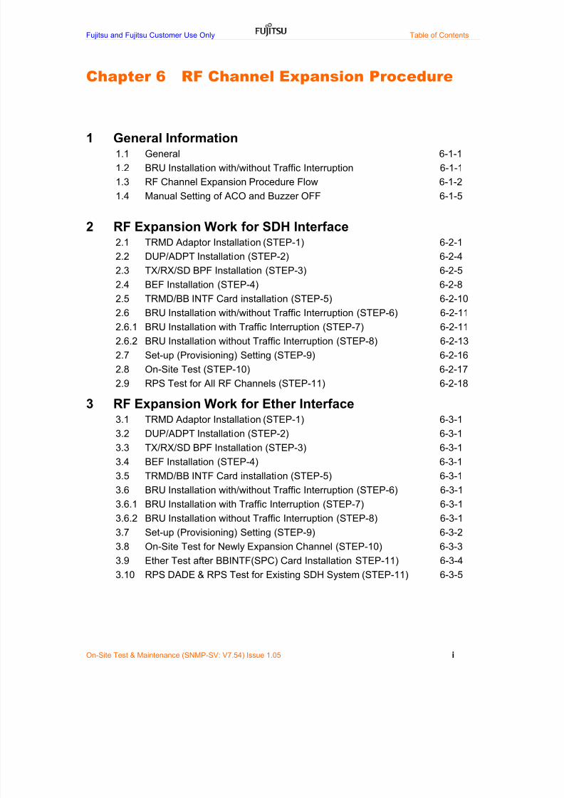
7/24/2019 Frx-3e Test v7.55 Issue1.06 June2014
http://slidepdf.com/reader/full/frx-3e-test-v755-issue106-june2014 169/214
Fujitsu and Fujitsu Customer Use Only Table of Contents
On-Site Test & Maintenance (SNMP-SV: V7.54) Issue 1.05 i
Chapter 6 RF Channel Expansion Procedure
1 General Information1.1 General 6-1-1
1.2 BRU Installation with/without Traffic Interruption 6-1-1
1.3 RF Channel Expansion Procedure Flow 6-1-2
1.4 Manual Setting of ACO and Buzzer OFF 6-1-5
2 RF Expansion Work for SDH Interface
2.1 TRMD Adaptor Installation (STEP-1) 6-2-12.2 DUP/ADPT Installation (STEP-2) 6-2-4
2.3 TX/RX/SD BPF Installation (STEP-3) 6-2-5
2.4 BEF Installation (STEP-4) 6-2-8
2.5 TRMD/BB INTF Card installation (STEP-5) 6-2-10
2.6 BRU Installation with/without Traffic Interruption (STEP-6) 6-2-11
2.6.1 BRU Installation with Traffic Interruption (STEP-7) 6-2-11
2.6.2 BRU Installation without Traffic Interruption (STEP-8) 6-2-13
2.7 Set-up (Provisioning) Setting (STEP-9) 6-2-16
2.8 On-Site Test (STEP-10) 6-2-17
2.9 RPS Test for All RF Channels (STEP-11) 6-2-18
3 RF Expansion Work for Ether Interface3.1 TRMD Adaptor Installation (STEP-1) 6-3-1
3.2 DUP/ADPT Installation (STEP-2) 6-3-1
3.3 TX/RX/SD BPF Installation (STEP-3) 6-3-1
3.4 BEF Installation (STEP-4) 6-3-1
3.5 TRMD/BB INTF Card installation (STEP-5) 6-3-1
3.6 BRU Installation with/without Traffic Interruption (STEP-6) 6-3-1
3.6.1 BRU Installation with Traffic Interruption (STEP-7) 6-3-1
3.6.2 BRU Installation without Traffic Interruption (STEP-8) 6-3-1
3.7 Set-up (Provisioning) Setting (STEP-9) 6-3-2
3.8 On-Site Test for Newly Expansion Channel (STEP-10) 6-3-3
3.9 Ether Test after BBINTF(SPC) Card Installation STEP-11) 6-3-4
3.10 RPS DADE & RPS Test for Existing SDH System (STEP-11) 6-3-5

7/24/2019 Frx-3e Test v7.55 Issue1.06 June2014
http://slidepdf.com/reader/full/frx-3e-test-v755-issue106-june2014 170/214
Fujitsu and Fujitsu Customer Use Only Table of Contents
On-Site Test & Maintenance (SNMP-SV: V7.54) Issue 1.05 ii
This page intent ional ly left blank

7/24/2019 Frx-3e Test v7.55 Issue1.06 June2014
http://slidepdf.com/reader/full/frx-3e-test-v755-issue106-june2014 171/214
Fujitsu and Fujitsu Customer Use Only RF Channel Expansion Procedure
On-Site test & Maintenance (SNMP-SV: V7.54) Issue 1.05 6-1-1
1 General Information
1.1 General
Necessary installation for RF Channel Expansion on site is summarized asfollows;--
TRMD Adaptor installation, if necessary
Duplexer and/or Adaptor Installation, if necessary
TX/RX/SD filter unit installation to the TRMD Adaptor
BEF filter unit installation to the TR Adaptor, if necessary
TRMD/BBINTF/GESW/GE ADPT/BBINTF(SPC) card installation basedon RF channel expansion plan
Provisional Data Setting
Coaxial cable connection between circulators on filter unit
On-Site test and confirmation of traffic for RF channel expansion
1.2 BRU Installation with/without Traffic Interruption
There are two types of BRU installation, one is BRU installation with trafficinterruption and the other is BRU installation without traffic interruption.
In case that Space Diversity (SD) reception is not applied
When BRU network is loss equalized (Loss equalized BRU network isstandard configuration for FRX-3E), BRU installation with trafficinterruption is essential.
When the Customer strongly wants to maintain BRU network withouttraffic interruption when RF channel expansion is needed, full BRUnetwork installation at initial stage is recommended.
In case that Space diversity (SD) reception is applied
BRU installation without traffic interruption is possible. However greatcare should be taken for BRU installation procedure.
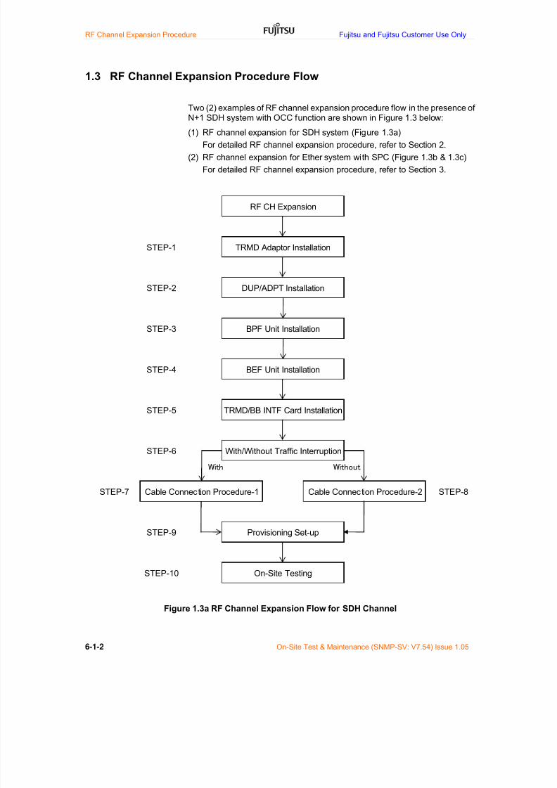
7/24/2019 Frx-3e Test v7.55 Issue1.06 June2014
http://slidepdf.com/reader/full/frx-3e-test-v755-issue106-june2014 172/214
RF Channel Expansion Procedure Fujitsu and Fujitsu Customer Use Only
6-1-2 On-Site Test & Maintenance (SNMP-SV: V7.54) Issue 1.05
1.3 RF Channel Expansion Procedure Flow
Two (2) examples of RF channel expansion procedure flow in the presence of
N+1 SDH system with OCC function are shown in Figure 1.3 below:(1) RF channel expansion for SDH system (Figure 1.3a)
For detailed RF channel expansion procedure, refer to Section 2.
(2) RF channel expansion for Ether system with SPC (Figure 1.3b & 1.3c)
For detailed RF channel expansion procedure, refer to Section 3.
Figure 1.3a RF Channel Expansion Flow for SDH Channel
With Without
With/Without Traffic Interruption
Cable Connection Procedure-1 Cable Connection Procedure-2
Provisioning Set-up
On-Site Testing
STEP-6
RF CH Expansion
TRMD Adaptor Installation
DUP/ADPT Installation
BPF Unit Installation
BEF Unit Installation
TRMD/BB INTF Card Installation
STEP-7 STEP-8
STEP-9
STEP-10
STEP-1
STEP-2
STEP-3
STEP-4
STEP-5

7/24/2019 Frx-3e Test v7.55 Issue1.06 June2014
http://slidepdf.com/reader/full/frx-3e-test-v755-issue106-june2014 173/214
Fujitsu and Fujitsu Customer Use Only RF Channel Expansion Procedure
On-Site test & Maintenance (SNMP-SV: V7.54) Issue 1.05 6-1-3
Figure 1.3b RF Channel Expansion Flow for Ether Channel
(When BBINTF (SPC) is not installed)
With Without
STEP-9 Provisioning Setting
STEP-10 On-Site Test
STEP-6 With/Without Traffic Interruption
STEP-7 Cable Connection Procedure-1 Cable Connection Procedure-2 STEP-8
STEP-3 BPF Unit Installation
STEP-4 BEF Unit Installation
STEP-5TRMD/GESW/GEADPT
Installation
RF CH Expansion
STEP-1 TRMD Adaptor Installation
STEP-2 DUP/ADPT Installation

7/24/2019 Frx-3e Test v7.55 Issue1.06 June2014
http://slidepdf.com/reader/full/frx-3e-test-v755-issue106-june2014 174/214
RF Channel Expansion Procedure Fujitsu and Fujitsu Customer Use Only
6-1-4 On-Site Test & Maintenance (SNMP-SV: V7.54) Issue 1.05
Figure 1.3b RF Channel Expansion Flow for Ether Channel(When BBINTF (SPC) is installed instead of BBINTF (STM1E/O))
With Without
m+0 Ether Test
RPS DADE & RPS Test for
existing SDH system
STEP-12
STEP-13
STEP-11
RF CH Expansion
STEP-1 TRMD Adaptor Installation
STEP-2 DUP/ADPT Installation
BBINTF(SPC) Installation
instead of BBINTF(STM1E/O)
STEP-7 Cable Connection Procedure-1 Cable Connection Procedure-2
STEP-3 BPF Unit Installation
STEP-4 BEF Unit Installation
STEP-5TRMD/GESW/GEADPT/
BBINTF(SPC) Installation
STEP-8
STEP-9 Provisioning Setting
STEP-10 On-Site Test
STEP-6 With/Without Traffic Interruption

7/24/2019 Frx-3e Test v7.55 Issue1.06 June2014
http://slidepdf.com/reader/full/frx-3e-test-v755-issue106-june2014 175/214
Fujitsu and Fujitsu Customer Use Only RF Channel Expansion Procedure
On-Site test & Maintenance (SNMP-SV: V7.54) Issue 1.05 6-1-5
1.4 Manual Setting of ACO and Buzzer OFF
Prior to RF channel expansion work, visual and audible alarm should be OFFfor the maintenance purpose point of view as shown in Table 1.4.
Table 1.4 Alarm Cut Off and Buzzer Off
Item Description Remarks
Alarm Cut Off (ACO) ACO switch on SV card ON
Alarm Cut Off (ACO) RAB information from externalequipment.
Buzzer Off (BZ OFF) Buzzer EN switch on SV card OFF
OPEN = Buzzer Disable CLOSE = Buzzer Enable
CLOSE OPEN
Factory use
(Default = Open)
Buzzer Enable
BZ EN switch

7/24/2019 Frx-3e Test v7.55 Issue1.06 June2014
http://slidepdf.com/reader/full/frx-3e-test-v755-issue106-june2014 176/214
RF Channel Expansion Procedure Fujitsu and Fujitsu Customer Use Only
6-1-6 On-Site Test & Maintenance (SNMP-SV: V7.54) Issue 1.05
This page intent ional ly left blank

7/24/2019 Frx-3e Test v7.55 Issue1.06 June2014
http://slidepdf.com/reader/full/frx-3e-test-v755-issue106-june2014 177/214
Fujitsu and Fujitsu Customer Use Only RF Channel Expansion Procedure
On-Site test & Maintenance (SNMP-SV: V7.54) Issue 1.05 6-2-1
2 RF Expansion Work for SDH Interface
This RF expansion work describes the detailed procedures necessary forSDH channel expansion work on site and existing system is N+1 SDH systemwith OCC as an example.
2.1 TRMD Adaptor Installation (STEP-1)
Figure 2.1 TRMD Adaptor Installation to the Basic Shelf
TRMD Adaptor is fixed byscrews at the top and bottom tothe TRMD shelf on 2xTRMD

7/24/2019 Frx-3e Test v7.55 Issue1.06 June2014
http://slidepdf.com/reader/full/frx-3e-test-v755-issue106-june2014 178/214
RF Channel Expansion Procedure Fujitsu and Fujitsu Customer Use Only
6-2-2 On-Site Test & Maintenance (SNMP-SV: V7.54) Issue 1.05
Figure 2.1b Front Side of TRMD Adaptor
(2xTRMD ADPTs for max. 4 RF CH expansion)
VENT Plug-in(max. 2xVENTs)
BPF Plug-in(max. x 6 BPFs)
Fixing Point tothe TR ADPT
Fixing Point tothe TR ADPT
TRMDAdaptor

7/24/2019 Frx-3e Test v7.55 Issue1.06 June2014
http://slidepdf.com/reader/full/frx-3e-test-v755-issue106-june2014 179/214
Fujitsu and Fujitsu Customer Use Only RF Channel Expansion Procedure
On-Site test & Maintenance (SNMP-SV: V7.54) Issue 1.05 6-2-3
Figure 2.1c Rear Side of TRMD Adaptor
(1xTRMD card and 6xBPF units are plug-in’ed)
Plug-in CN forTRMD card (x3)
Plug-in CN forBPF unit (x6)
Semi-rigid coaxialcable (x6)

7/24/2019 Frx-3e Test v7.55 Issue1.06 June2014
http://slidepdf.com/reader/full/frx-3e-test-v755-issue106-june2014 180/214
RF Channel Expansion Procedure Fujitsu and Fujitsu Customer Use Only
6-2-4 On-Site Test & Maintenance (SNMP-SV: V7.54) Issue 1.05
2.2 DUP/ADPT Installation (STEP-2)
Typical Duplexer/Adapter installation of ACAP operation using V (H)-polarization with SD is shown in Figure 2.2 as an example.
And typical antenna port location on top of TRMD shelf is described inChapter 4, Section 4.2, Waveguide Connection of Installation Manual.
Figure 2.2 Typical DUP/ADP Installation
TRMD Shelf Front
Adaptor (ADPT) for space diversity (SD)reception port from antenna system ofV (H) - polarization
ADP/cables are installed at factory.
Adapter (ADPT) for Space diversity(SD) reception port from antennasystem of V (H) - polarization
ADPT/cablea will be installed on site atthe time of RF CH expansion.
Transmit-Receive Duplexer (DUP) fortransmit and main receiver port to/fromantenna system of V (H) - polarizationfor initial stage
DUP/cables will be installed at factory.
Transmit-Receive Duplexer (DUP) fortransmit and main receive port to/fromantenna system of H (V)-polarizationfor future RF expansion.
DUP/cables will be installed on site at thetime of RF CH expansion.

7/24/2019 Frx-3e Test v7.55 Issue1.06 June2014
http://slidepdf.com/reader/full/frx-3e-test-v755-issue106-june2014 181/214
Fujitsu and Fujitsu Customer Use Only RF Channel Expansion Procedure
On-Site test & Maintenance (SNMP-SV: V7.54) Issue 1.05 6-2-5
2.3 TX/RX/SD BPF Unit Installation (STEP-3)
After TRMD Adaptor installation, necessary BPF units are installed to the
TRMD Adaptor as shown in Figure 2.3.
Figure 2.3a Typical BPF Unit Installation
TRMD Adaptor has max. 6 BPF unitslots for 2xTRMD cards located 2xTX,2xRX and 2xSD BPF units from thebottom.
Each BPF unit is plug-in’ed to the TRADPT and fixed by screw on unit.
Connection between BPFs, DUP &BPF and ADPT & BPF are made bysemi-rigid coaxial cable.

7/24/2019 Frx-3e Test v7.55 Issue1.06 June2014
http://slidepdf.com/reader/full/frx-3e-test-v755-issue106-june2014 182/214
RF Channel Expansion Procedure Fujitsu and Fujitsu Customer Use Only
6-2-6 On-Site Test & Maintenance (SNMP-SV: V7.54) Issue 1.05
BPF unit (BPF + CIR type)
Plug-in Connector of BPF unit (Male)
Plug-in Connector of TR Adaptor (Female)
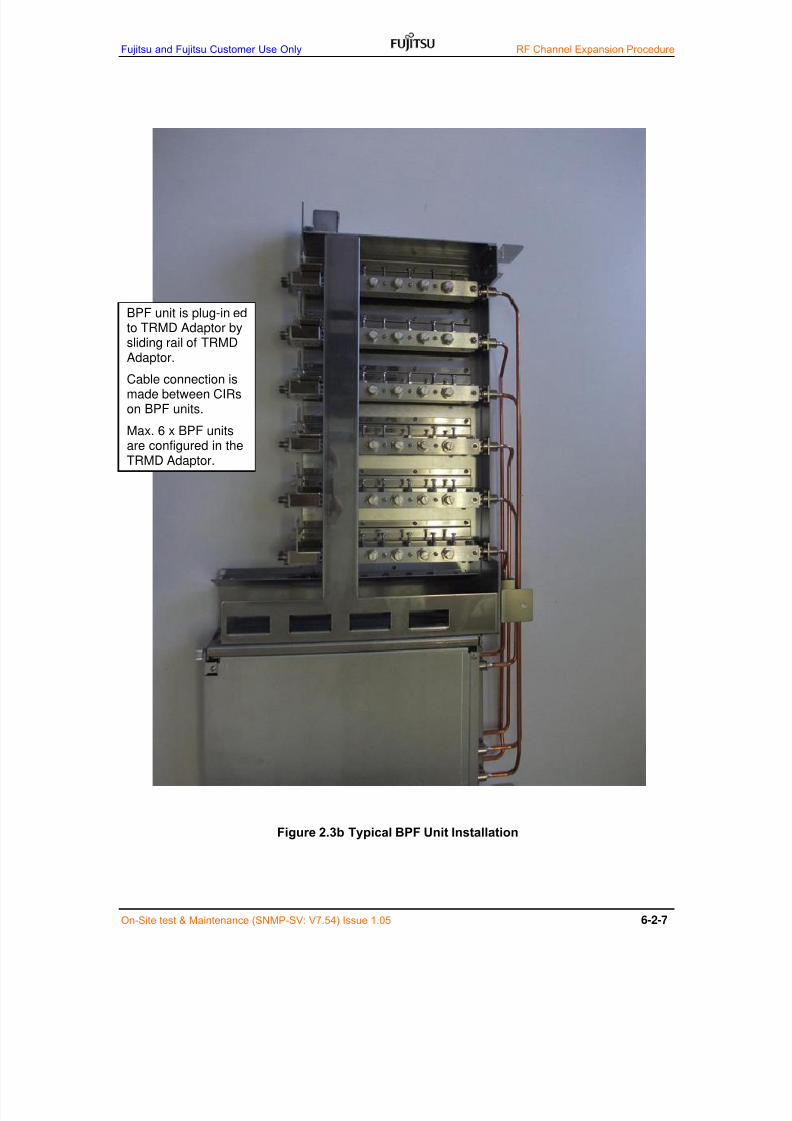
7/24/2019 Frx-3e Test v7.55 Issue1.06 June2014
http://slidepdf.com/reader/full/frx-3e-test-v755-issue106-june2014 183/214
Fujitsu and Fujitsu Customer Use Only RF Channel Expansion Procedure
On-Site test & Maintenance (SNMP-SV: V7.54) Issue 1.05 6-2-7
Figure 2.3b Typical BPF Unit Installation
BPF unit is plug-in’edto TRMD Adaptor by
sliding rail of TRMDAdaptor.
Cable connection ismade between CIRson BPF units.
Max. 6 x BPF unitsare configured in theTRMD Adaptor.

7/24/2019 Frx-3e Test v7.55 Issue1.06 June2014
http://slidepdf.com/reader/full/frx-3e-test-v755-issue106-june2014 184/214
RF Channel Expansion Procedure Fujitsu and Fujitsu Customer Use Only
6-2-8 On-Site Test & Maintenance (SNMP-SV: V7.54) Issue 1.05
2.4 BEF Unit Installation (STEP-4)
BEF unit installation is generally carried out when innermost RF channel pairis allocated and technical consideration with/without BEF depends on projectsystem designer.
Figure 2.4a Typical BEF Unit Installation
BEF unit is installed when innermostRF channel pair is allocated.
BEF is installed in the upper part ofBRU block and quantity of BEF isdependent of system operation suchas ACCP, ACAP and CCDP.
Maximum x8 BEFs are installed.
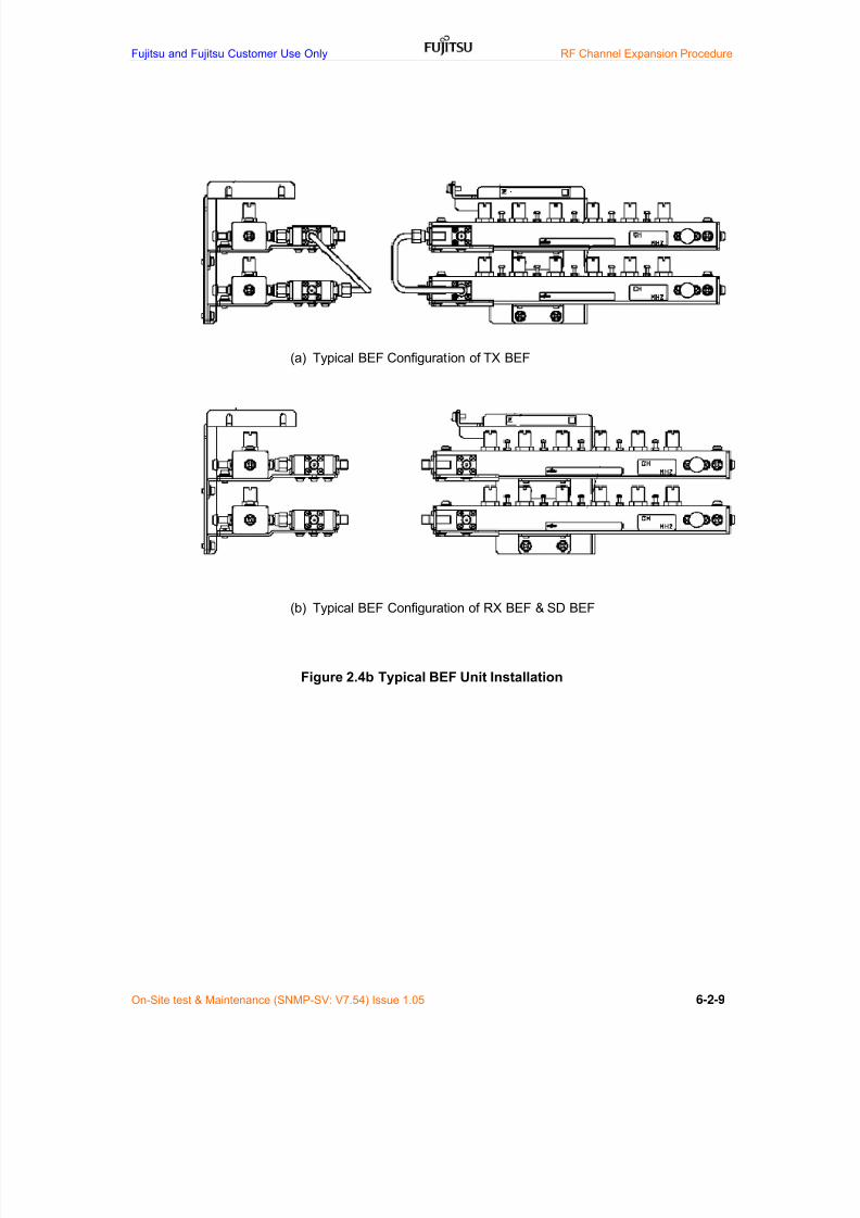
7/24/2019 Frx-3e Test v7.55 Issue1.06 June2014
http://slidepdf.com/reader/full/frx-3e-test-v755-issue106-june2014 185/214
Fujitsu and Fujitsu Customer Use Only RF Channel Expansion Procedure
On-Site test & Maintenance (SNMP-SV: V7.54) Issue 1.05 6-2-9
(a) Typical BEF Configuration of TX BEF
(b) Typical BEF Configuration of RX BEF & SD BEF
Figure 2.4b Typical BEF Unit Installation

7/24/2019 Frx-3e Test v7.55 Issue1.06 June2014
http://slidepdf.com/reader/full/frx-3e-test-v755-issue106-june2014 186/214
RF Channel Expansion Procedure Fujitsu and Fujitsu Customer Use Only
6-2-10 On-Site Test & Maintenance (SNMP-SV: V7.54) Issue 1.05
2.5 TRMD and BB INTF Card Installation (STEP-5)
Prior to RF channel expansion work, visual and audible alarm should be OFFfor the maintenance purpose point of view as shown in Table 1.4.
TRMD card is plug-in’ed to theBasic shelf and TRMD card hasonly one (1) latch at the bottomand one (1) mounting screw at thetop of card.
BBINTF (STM1EO), BBINTF (SPC) andGE ADPT cards are plug-in’ed to theBasic shelf. BBINTF (STM1E/O),BBINTF (SPC) and GE ADPT have onlyone (1) latch at the bottom. And GESWhas two (2) latchs. After mountingslide-in- cards, all cards are locked bypull-out-protection metal plates.

7/24/2019 Frx-3e Test v7.55 Issue1.06 June2014
http://slidepdf.com/reader/full/frx-3e-test-v755-issue106-june2014 187/214
Fujitsu and Fujitsu Customer Use Only RF Channel Expansion Procedure
On-Site test & Maintenance (SNMP-SV: V7.54) Issue 1.05 6-2-11
2.6 BRU Installation With/Without Traffic Interruption (STEP-6)
There are generally two (2) types of loss equalized BRU installation when RFchannel expansion is carried out. One is BRU installation with trafficinterruption when SD reception is not applied and the other is BRU installationwithout traffic interruption when SD reception is applied.
NOTICE: Provided BRU installation without traffic interruption is essential for
customer ’s request, BRU arrangement with full RF channels is recommendedin the initial stage.
2.6.1 BRU Installation with Traffic Interruption (STEP-7)
Figure 2.6-1 shows the schematic explanation of BRU installation with traffic
interruption when SD reception is not applied.
Figure 2.6-1a BRU Installation with Traffic Interruption (TX Side)
DUP
CIR CIR CIR CIR DL
BPF BPF BPF BPF
CH1 CH2 CH3 CH4
Initial 3+1 Operation
DUP
CIR CIR CIR CIR
BRU installa tion without traffic interruption
CIR DL
BPF BPF BPF BPF BPF BPF
Expansion to 5+1 Operation
due to no cable connection change
Loss Equalized RF Branching Network Expansion (Transmit Side)
CH1 CH2 CH3 CH4 CH5 CH6
CIR

7/24/2019 Frx-3e Test v7.55 Issue1.06 June2014
http://slidepdf.com/reader/full/frx-3e-test-v755-issue106-june2014 188/214
RF Channel Expansion Procedure Fujitsu and Fujitsu Customer Use Only
6-2-12 On-Site Test & Maintenance (SNMP-SV: V7.54) Issue 1.05
Figure 2.6-1b BRU Installation with Traffic Interruption (RX Side)
CH2 CH3 CH4
CIR CIR CIR CIR
Initial 3+1 Operation
CIR CIR CIR CIR
BPF BPF BPF BPF
CH1
BPF BPF BPF BPF BPF BPF
CH2 CH3 CH4 CH5 CH6
CIR CIR
BRU installation with traffic interruption
Loss Equalized RF Branching Network Expansion (Receive Side)
due to cable connection change
Expansion to 5+1 Operation
DUP
DL
DUP
DL
CH1

7/24/2019 Frx-3e Test v7.55 Issue1.06 June2014
http://slidepdf.com/reader/full/frx-3e-test-v755-issue106-june2014 189/214
Fujitsu and Fujitsu Customer Use Only RF Channel Expansion Procedure
On-Site test & Maintenance (SNMP-SV: V7.54) Issue 1.05 6-2-13
2.6.2 BRU Installation without Traffic Interruption (STEP-8)
Figure 2.6-2 shows the schematic explanation of BRU installation withouttraffic interruption when SD reception is not applied.
Figure 2.6-2a BRU Installation without Traffic Interruption (TX Side)
DUP
CIR CIR CIR CIR DL
BPF BPF BPF BPF
CH1 CH2 CH3 CH4
Initial 3+1 Operation
DUP
CIR CIR CIR CIR
BRU installa tion without traffic interruption
CIR DL
BPF BPF BPF BPF BPF BPF
Expansion to 5+1 Operation
due to no cable connection change
Loss Equalized RF Branching Network Expansion (Transmit Side)
CH1 CH2 CH3 CH4 CH5 CH6
CIR

7/24/2019 Frx-3e Test v7.55 Issue1.06 June2014
http://slidepdf.com/reader/full/frx-3e-test-v755-issue106-june2014 190/214
RF Channel Expansion Procedure Fujitsu and Fujitsu Customer Use Only
6-2-14 On-Site Test & Maintenance (SNMP-SV: V7.54) Issue 1.05
Figure 2.6-2b-1 BRU Installation without Traffic Interruption (RX Side)
DUP
DL CIR CIR CIR CIR
RX BRU side
BPF BPF BPF BPF
CH1 CH2 CH3 CH4
Initial 3+1 Operation
DUP
BRU installtion w ithout traffic interruption
because SD RX is still working
DL CIR CIR CIR CIR CIR CIR
BPF BPF BPF BPF BPF BPF
CH1 CH2 CH3 CH4 CH5 CH6
DL CIR CIR CIR CIR
BPF BPF
SDRX BRU side
STEP-1: Loss Equalized RF Branching Network Expansion (Receive Side Installation)
BPF BPF
CH1 CH2 CH3 CH4
Expansion to 5+1 Operation
ADPT
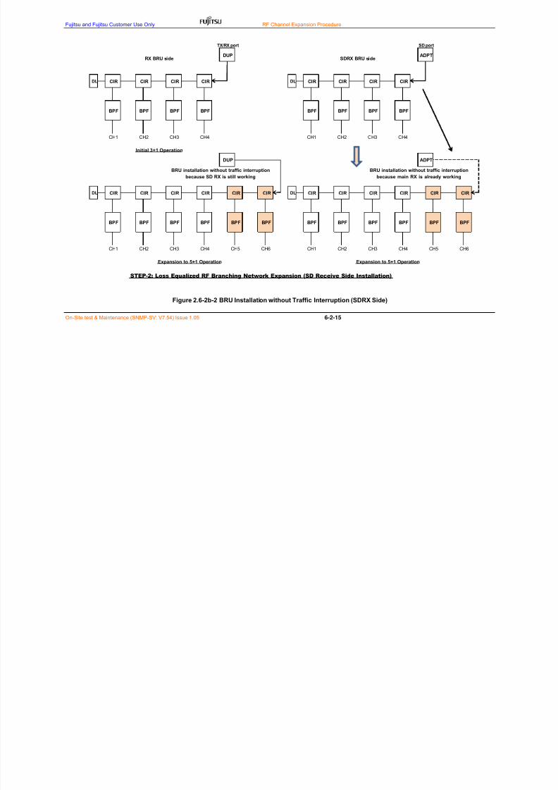
7/24/2019 Frx-3e Test v7.55 Issue1.06 June2014
http://slidepdf.com/reader/full/frx-3e-test-v755-issue106-june2014 191/214
Fujitsu and Fujitsu Customer Use Only RF Channel Expansion Procedure
On-Site test & Maintenance (SNMP-SV: V7.54) Issue 1.05 6-2-15
Figure 2.6-2b-2 BRU Installation without Traffic Interruption (SDRX Side)
DUP ADPTRX BRU side SDRX BRU side
DL CIR CIR CIR CIR DL CIR CIR CIR CIR
BPF BPF BPF BPF BPF BPF BPF BPF
CH1 CH2 CH3 CH4 CH1 CH2 CH3 CH4
Initial 3+1 Operation
DUP
BRU installation without traffic interruption
because SD RX is still working
DL CIR CIR CIR CIR CIR CIR
BPF BPF BPF BPF BPF BPF
CH1 CH2 CH3 CH4 CH5 CH6
Expansion to 5+1 Operation
STEP-2: Loss Equalized RF Branching Network Expansion (SD Receive Side Installation)
TX/RX port SD port
ADPT
BRU installation without traffic interruption
because main RX is already working
DL CIR CIR CIR CIR CIR CIR
BPF BPF BPF BPF BPF
Expansion to 5+1 Operation
BPF
CH1 CH2 CH3 CH4 CH5 CH6
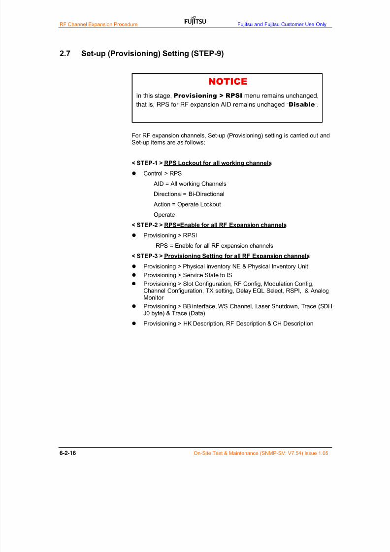
7/24/2019 Frx-3e Test v7.55 Issue1.06 June2014
http://slidepdf.com/reader/full/frx-3e-test-v755-issue106-june2014 192/214
RF Channel Expansion Procedure Fujitsu and Fujitsu Customer Use Only
6-2-16 On-Site Test & Maintenance (SNMP-SV: V7.54) Issue 1.05
2.7 Set-up (Provisioning) Setting (STEP-9)
For RF expansion channels, Set-up (Provisioning) setting is carried out andSet-up items are as follows;
< STEP-1 > RPS Lockout for all working channels
Control > RPS
AID = All working Channels
Directional = Bi-Directional
Action = Operate Lockout
Operate
< STEP-2 > RPS=Enable for all RF Expansion channels
Provisioning > RPSI
RPS = Enable for all RF expansion channels
< STEP-3 > Provisioning Setting for all RF Expansion channels
Provisioning > Physical inventory NE & Physical Inventory Unit
Provisioning > Service State to IS
Provisioning > Slot Configuration, RF Config, Modulation Config,Channel Configuration, TX setting, Delay EQL Select, RSPI, & AnalogMonitor
Provisioning > BB interface, WS Channel, Laser Shutdown, Trace (SDHJ0 byte) & Trace (Data)
Provisioning > HK Description, RF Description & CH Description
NOTICEIn this stage, Provisioning > RPSI menu remains unchanged,
that is, RPS for RF expansion AID remains unchaged “Disable”.
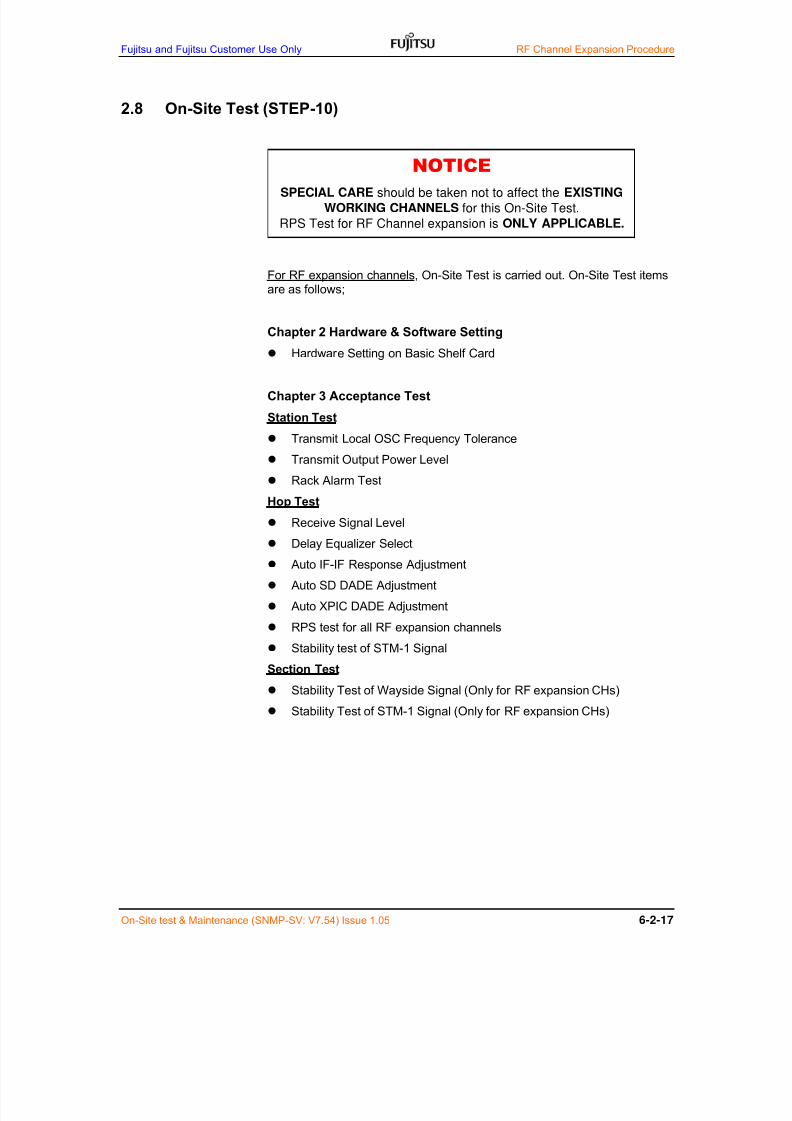
7/24/2019 Frx-3e Test v7.55 Issue1.06 June2014
http://slidepdf.com/reader/full/frx-3e-test-v755-issue106-june2014 193/214
Fujitsu and Fujitsu Customer Use Only RF Channel Expansion Procedure
On-Site test & Maintenance (SNMP-SV: V7.54) Issue 1.05 6-2-17
2.8 On-Site Test (STEP-10)
For RF expansion channels, On-Site Test is carried out. On-Site Test itemsare as follows;
Chapter 2 Hardware & Software Setting
Hardware Setting on Basic Shelf Card
Chapter 3 Acceptance Test
Station Test
Transmit Local OSC Frequency Tolerance
Transmit Output Power Level
Rack Alarm Test
Hop Test
Receive Signal Level
Delay Equalizer Select
Auto IF-IF Response Adjustment
Auto SD DADE Adjustment
Auto XPIC DADE Adjustment
RPS test for all RF expansion channels
Stability test of STM-1 Signal
Section Test
Stability Test of Wayside Signal (Only for RF expansion CHs)
Stability Test of STM-1 Signal (Only for RF expansion CHs)
NOTICESPECIAL CARE should be taken not to affect the EXISTING
WORKING CHANNELS for this On-Site Test.
RPS Test for RF Channel expansion is ONLY APPLICABLE.
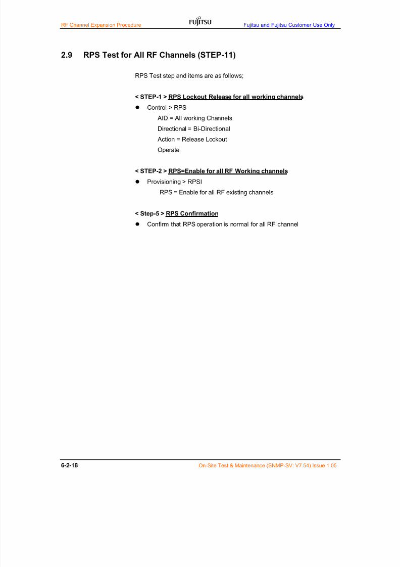
7/24/2019 Frx-3e Test v7.55 Issue1.06 June2014
http://slidepdf.com/reader/full/frx-3e-test-v755-issue106-june2014 194/214
RF Channel Expansion Procedure Fujitsu and Fujitsu Customer Use Only
6-2-18 On-Site Test & Maintenance (SNMP-SV: V7.54) Issue 1.05
2.9 RPS Test for All RF Channels (STEP-11)
RPS Test step and items are as follows;
< STEP-1 > RPS Lockout Release for all working channels
Control > RPS
AID = All working Channels
Directional = Bi-Directional
Action = Release Lockout
Operate
< STEP-2 > RPS=Enable for all RF Working channels Provisioning > RPSI
RPS = Enable for all RF existing channels
< Step-5 > RPS Confirmation
Confirm that RPS operation is normal for all RF channel

7/24/2019 Frx-3e Test v7.55 Issue1.06 June2014
http://slidepdf.com/reader/full/frx-3e-test-v755-issue106-june2014 195/214
Fujitsu and Fujitsu Customer Use Only RF Channel Expansion Procedure
On-Site test & Maintenance (SNMP-SV: V7.54) Issue 1.05 6-3-1
3 RF Expansion Work for Ether Interface
This RF expansion work describes the detailed procedures necessary forEther channel expansion work with SPC on site and the existing system isN+1 SDH system with OCC as an example.
3.1 TRMD Adaptor Installation (STEP-1)
Same as Chapter 2, Section 2.1
3.2 DUP/ADPT Installation (STEP-2)
Same as Chapter 2, Section 2.2
3.3 TX/RX/SD BPF Unit Installation (STEP-3)
Same as Chapter 2, Section 2.3
3.4 BEF Unit Installation (STEP-4)Same as Chapter 2, Section 2.4
3.5 TRMD and Ether Card Installation (STEP-5)
Same as Chapter 2, Section 2.5
3.6 BRU Installation With/Without Traffic Interruption (STEP-6)
Same as Chapter 2, Section 2.6
3.6.1 BRU Installation with Traffic Interruption (STEP-7)
Same as Chapter 2, Section 2.6.1
3.6.2 BRU Installation without Traffic Interruption (STEP-8)
Same as Chapter 2, Section 2.6.2

7/24/2019 Frx-3e Test v7.55 Issue1.06 June2014
http://slidepdf.com/reader/full/frx-3e-test-v755-issue106-june2014 196/214
RF Channel Expansion Procedure Fujitsu and Fujitsu Customer Use Only
6-3-2 On-Site Test & Maintenance (SNMP-SV: V7.54) Issue 1.05
3.7 Provisioning Setting (STEP-9)
< STEP-1 > RPS Lockout for all existing SDH channels
Contriol > RPS
AID = All existing SDH channels
Directional = Bi-Directional
Action = Operate Lockout
Operate
< STEP-2 > RF Setting Set-up
Provisioning > RPSI
AID = BBINTF (STM1E/O) card channel
OCC = Disable
Operate
< STEP-3 > BBINTF (SPC) Installation
Replace BBINTF(STM1E/O) card to BBINTF (SPC) card.
< STEP-4 > Provisioning Setting for RF Expansion Channel
Provisioning > Pysical Inventory NE, Pysical Inventory Unit
Provisioning > Service State to IS
Provisioning > Slot Configuration, RF Config, Modulation Config,Channel Configuration, TX setting, Delay EQL Select, & Analog Monitor
Provisioning > BB interface
GESW v1 > Composition Setting
GESW v2 > Composition Setting & Radio Port Setting (*1) (*2)
GESW-L2SW setting only for GESW v2
Provisioning > HK Description, RF Description & CH Description
NOTE-*1: For Composition Setting and Radio Port Setting on GESW v2 forRF channel expansion, please refer to WebLT Manual, Chapter 5 Set-up-1(Provisioning a System) (When GESW v2 is installed), Section 7.2 & 7.3.
NOTICE-*2: Composition setting for BBINTF (SPC) cards both near-end and
far-end station should be equal.
NOTICE
In this stage, Provisioning > RPSI menu remains unchanged,that is, RPS for RF expansion AID remains unchaged “Disable”.

7/24/2019 Frx-3e Test v7.55 Issue1.06 June2014
http://slidepdf.com/reader/full/frx-3e-test-v755-issue106-june2014 197/214
Fujitsu and Fujitsu Customer Use Only RF Channel Expansion Procedure
On-Site test & Maintenance (SNMP-SV: V7.54) Issue 1.05 6-3-3
3.8 On-Site Test for RF Newly Expansion Channels (STEP-10)
For newly RF expansion channels, On-Site Test is carried out in accordancewith On-Site & Maintenance Manual. Test items are as follows;
< Step-1 >
Chapter 2 Hardware & Software Setting
Hardware Setting on Basic Shelf Card
< Step-2 >
Chapter 3 Acceptance Test
Station Test
Transmit Local OSC Frequency Tolerance
Transmit Output Power Level
Rack Alarm Test
Hop Test
Receive Signal Level
Delay Equalizer Select
Auto IF-IF Response Adjustment
Auto SD DADE Adjustment
Auto XPIC DADE Adjustment
Gigabit Ethernet Transmission Test
Section Test
Gigabit Ethernet Transmission Test
< Step-3 >
Confirm that On-Site test is completed satisfactory.
NOTICE
SPECIAL CARE should be taken not to affect the EXISTING
SDH WORKING CHANNELS for this On-Site Test

7/24/2019 Frx-3e Test v7.55 Issue1.06 June2014
http://slidepdf.com/reader/full/frx-3e-test-v755-issue106-june2014 198/214
RF Channel Expansion Procedure Fujitsu and Fujitsu Customer Use Only
6-3-4 On-Site Test & Maintenance (SNMP-SV: V7.54) Issue 1.05
3.9 Ether Test after BBINTF (SPC) Card Installation (STEP-11)
RPS Test step and items are as follows;
< STEP-1 > RF Setting Set-up
Provisioning > RPSI
AID = BBINTF (SPC) card channel
OCC = Enable
Operate
< Step-2 >
Chapter 3 Acceptance Test
Hop Test
Gigabit Ethernet Transmission Test (*1)
Section Test Gigabit Ethernet Transmission Test
< Step-3 >
Confirm that on-site test for Ether is completed satisfactory.
NOTICE-*1: When BBINTF(SPC) card is inserted in the protection channelslot for GESW v2 Ethernet line expansion, radio link down alarm is issued inan moment and short traffic interruption occurs before the completion of delay
time equalization between SPC (155M line) and GE ADPT (466M line) lines. .
NOTICE
This procedure is only applicable when BBINTF (SPC) card isinstalled instead of STM-1 BBINTF (STM1E/O) card in the
protection channel slot ON SITE.
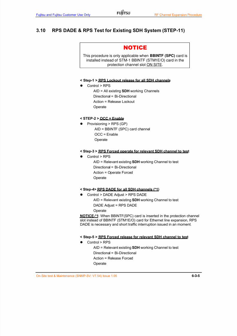
7/24/2019 Frx-3e Test v7.55 Issue1.06 June2014
http://slidepdf.com/reader/full/frx-3e-test-v755-issue106-june2014 199/214
Fujitsu and Fujitsu Customer Use Only RF Channel Expansion Procedure
On-Site test & Maintenance (SNMP-SV: V7.54) Issue 1.05 6-3-5
3.10 RPS DADE & RPS Test for Existing SDH System (STEP-11)
< Step-1 > RPS Lockout release for all SDH channels
Control > RPS
AID = All existing SDH working Channels
Directional = Bi-Directional
Action = Release LockoutOperate
< STEP-2 > OCC = Enable
Provisioning > RPS (GP)
AID = BBINTF (SPC) card channel
OCC = Enable
Operate
< Step-3 > RPS Forced operate for relevant SDH channel to test
Control > RPS
AID = Relevant existing SDH working Channel to test
Directional = Bi-Directional
Action = Operate Forced
Operate
< Step-4> RPS DADE for all SDH channels (*1)
Control > DADE Adjust > RPS DADE
AID = Relevant existing SDH working Channel to test
DADE Adjust = RPS DADE
Operate
NOTICE-*1: When BBINTF(SPC) card is inserted in the protection channel
slot instead of BBINTF (STM1E/O) card for Ethernet line expansion, RPSDADE is necessary and short traffic interruption issued in an moment.
< Step-5 > RPS Forced release for relevant SDH channel to test
Control > RPS
AID = Relevant existing SDH working Channel to test
Directional = Bi-Directional
Action = Release Forced
Operate
NOTICE
This procedure is only applicable when BBINTF (SPC) card isinstalled instead of STM-1 BBINTF (STM1E/O) card in the
protection channel slot ON SITE.
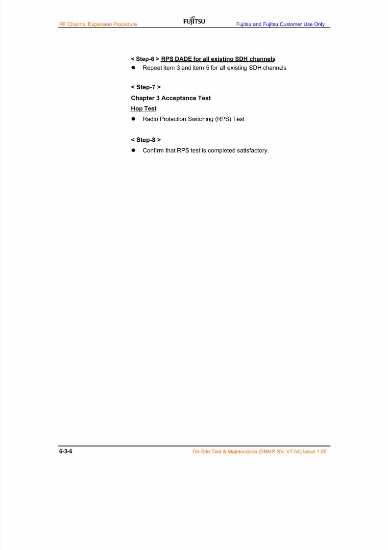
7/24/2019 Frx-3e Test v7.55 Issue1.06 June2014
http://slidepdf.com/reader/full/frx-3e-test-v755-issue106-june2014 200/214
RF Channel Expansion Procedure Fujitsu and Fujitsu Customer Use Only
6-3-6 On-Site Test & Maintenance (SNMP-SV: V7.54) Issue 1.05
< Step-6 > RPS DADE for all existing SDH channels
Repeat item 3 and item 5 for all existing SDH channels
< Step-7 >
Chapter 3 Acceptance Test
Hop Test
Radio Protection Switching (RPS) Test
< Step-8 >
Confirm that RPS test is completed satisfactory.

7/24/2019 Frx-3e Test v7.55 Issue1.06 June2014
http://slidepdf.com/reader/full/frx-3e-test-v755-issue106-june2014 201/214

7/24/2019 Frx-3e Test v7.55 Issue1.06 June2014
http://slidepdf.com/reader/full/frx-3e-test-v755-issue106-june2014 202/214

7/24/2019 Frx-3e Test v7.55 Issue1.06 June2014
http://slidepdf.com/reader/full/frx-3e-test-v755-issue106-june2014 203/214
On-Site Test & Maintenance (SNMP-SV: V7.54) Issue 1.05
1 System Upgrade by License Key
1.1 System Upgrade by License Key
License key procedure that enables system upgrade is as follows;
(1) Customer informs Serial Number of relevant cards to FWL
(Take TX high power output for example, inform relevant TRMD cardSerial Number to FWL)
(2) FWL creates license key file that enables optional system upgradeand delivers to the Customer with cost.
(3) Customer downloads license key file to the relevant cards fromWeb-based Local Terminal (Web LT) and optional system upgrade isenabled.
(4) License key file is only effective for the relevant card and it is alsohighly digitally encoded not to be known by analogy.
1.2 System Upgrade Item
System upgrade item by License Key is as follows;
TX High Power function
SD function
TX Overdrive
XPIC function
Adaptive Modulation (AM) function
Expansion Fixed QAM (Exp Fixed QAM) function
Wayside on SOH function (BB INTF-X/Y each) Wayside on RFCOH function (BB INTF-X/Y each)
GP2 / DT function

7/24/2019 Frx-3e Test v7.55 Issue1.06 June2014
http://slidepdf.com/reader/full/frx-3e-test-v755-issue106-june2014 204/214

7/24/2019 Frx-3e Test v7.55 Issue1.06 June2014
http://slidepdf.com/reader/full/frx-3e-test-v755-issue106-june2014 205/214
Issue 1.01 GTRMD TEST ADAPTOR
Document Code: T101-2256
Issue 1.01
Copyright © 2008 by FUJITSU WIRELESS SYSTEMS LIMITED
All rights reserved. This publication is for information only. No part of this publication may be reproduced, transmitted,
transcribed, stored in a retrieval system, or translated into any language or computer language, in any form or by any means,electronic, magnetic, optical, chemical, manual or otherwise, without the prior written permission of FUJITSU WIRELESSSYSTEMS LIMITED. The right is reserved to change information without notice. All brand names and product names aretrademarks and registered trademarks of their respective holders.
FRX-3E Technical Note A - 1
T101-2256-01,01,001
Appendix-A
APPLICATION NOTE
TRMD TEST ADAPTOR
(Direct RF Power Level Measurement Tool)

7/24/2019 Frx-3e Test v7.55 Issue1.06 June2014
http://slidepdf.com/reader/full/frx-3e-test-v755-issue106-june2014 206/214
TRMD TEST ADAPTOR Issue 1.01
FRX-3E Technical NoteA - 2
Document History
Date Issue Note
8 August 2012 1.01 First issue
7/24/2019 Frx-3e Test v7.55 Issue1.06 June2014
http://slidepdf.com/reader/full/frx-3e-test-v755-issue106-june2014 207/214
Issue1.01 TRMD TEST ADAPTOR
FRX-3E Technical Note A - 3
Contents
1. General Description -------------------------------------------------------------------------------- Page 4
2. Ordering Code --------------------------------------------------------------------------------------- Page 4
2.1 Configuration Tree ---------------------------------------------------------------------------- Page 4
2.2 Ordering Code --------------------------------------------------------------------------------- Page 4
3. Mechanical Description ---------------------------------------------------------------------------- Page 5
3.1 TRMD & BPF JIG ----------------------------------------------------------------------------- Page 5
4. How to Install ----------------------------------------------------------------------------------------- Page 6
4.1 TRMD & BPF JIG Mounting to the Basic Shelf ---------------------------------------- Page 6
5. How to Measure RF Power ----------------------------------------------------------------------- Page 7
5.1 On-Site RSL Measurement ----------------------------------------------------------------- Page 7
5.2 On-Site TX Power Measurement ---------------------------------------------------------- Page 9
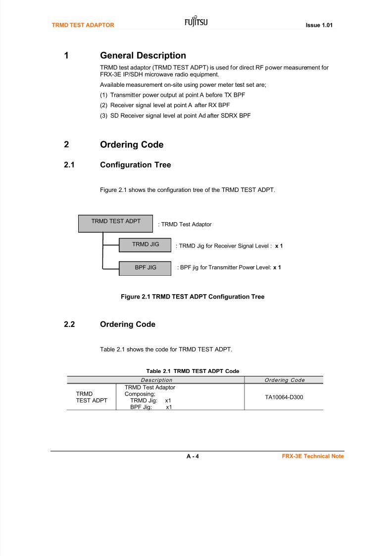
7/24/2019 Frx-3e Test v7.55 Issue1.06 June2014
http://slidepdf.com/reader/full/frx-3e-test-v755-issue106-june2014 208/214
TRMD TEST ADAPTOR Issue 1.01
FRX-3E Technical NoteA - 4
1 General Description
TRMD test adaptor (TRMD TEST ADPT) is used for direct RF power measurement forFRX-3E IP/SDH microwave radio equipment.
Available measurement on-site using power meter test set are;
(1) Transmitter power output at point A before TX BPF
(2) Receiver signal level at point A’ after RX BPF
(3) SD Receiver signal level at point Ad after SDRX BPF
2 Ordering Code
2.1 Configuration Tree
Figure 2.1 shows the configuration tree of the TRMD TEST ADPT.
Figure 2.1 TRMD TEST ADPT Configuration Tree
2.2 Ordering Code
Table 2.1 shows the code for TRMD TEST ADPT.
Table 2.1 TRMD TEST ADPT Code
Descr ipt ion Order ing Code
TRMDTEST ADPT
TRMD Test AdaptorComposing;
TRMD Jig: x1BPF Jig: x1
TA10064-D300
TRMD TEST ADPT
TRMD JIG
BPF JIG
: TRMD Jig for Receiver Signal Level : x 1
: BPF jig for Transmitter Power Level: x 1
: TRMD Test Adaptor

7/24/2019 Frx-3e Test v7.55 Issue1.06 June2014
http://slidepdf.com/reader/full/frx-3e-test-v755-issue106-june2014 209/214
Issue1.01 TRMD TEST ADAPTOR
FRX-3E Technical Note A - 5
3 Mechanical Description
3.1 TRMD & BPF Jig
Figure 3.1 TRMD TEST ADPT
TRMD JIG
BPF JIG
BMA type plug-in connector
BMA type plug-in connector
BPF JIG can be fixedon TRMD JIG.
SMA type connector
SMA type connector
Calibrationfactor labelof coaxialcable losson TRMD &BPF jigs
Calibration Label on Jig
11G
Calibration Loss (dB)
4G type1 0.2 0.15
4G type2 0.2 0.15
TRMD Jig BPF JigRF
5G 0.21 0.16
L6G 0.24 0.17
U6G 0.25 0.18
0.23
7G type1 0.26 0.18
7G type4 0.26 0.19
L8G 0.27 0.19
7G type5 0.26 0.18
0.34 0.22
13G 0.36

7/24/2019 Frx-3e Test v7.55 Issue1.06 June2014
http://slidepdf.com/reader/full/frx-3e-test-v755-issue106-june2014 210/214
TRMD TEST ADAPTOR Issue 1.01
FRX-3E Technical NoteA - 6
4 How to Install
4.1 TRMD & BPF Jig Mounting to the Basic Shelf
TRMD & BPF jigs are mounted to the shelf as shown Figure 4.1.
Figure 4.1 TRMD & BPF Jig Mounting to the Shelf
TRMD JIG Installation:
(1) Remove relevant TRMD
card.
(2) Install TRMD JIG instead
of TRMD card.
(3) Fix TRMD JIG by latch &screw.
(4) TRMD JIG has one latch
at the bottom and one
mounting screw at the
top.
BPF JIG Installation:
(1) Remove relevant plug-in
TX CH BPF.
(2) Install BPU JIG insteadof TX BPF.
(3) BPF JIG is directly plug-
in’ed to the TRMD ADPT
by sliding to the metal rail
(4) Fixed by metal screw.
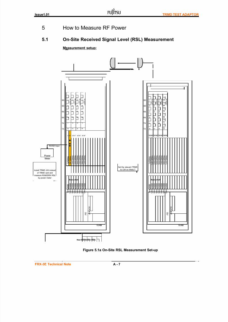
7/24/2019 Frx-3e Test v7.55 Issue1.06 June2014
http://slidepdf.com/reader/full/frx-3e-test-v755-issue106-june2014 211/214
Issue1.01 TRMD TEST ADAPTOR
FRX-3E Technical Note A - 7
5 How to Measure RF Power
5.1 On-Site Received Signal Level (RSL) Measurement
Measurement setup:
Figure 5.1a On-Site RSL Measurement Set-up
SD1 3 5 7
SD1 3 5 7
SDP 2 4 6
SDP 2 4 6
RX1 3 5 7
RX1 3 5 7
RXP 2 4 6
RXP 2 4 6
TX1 3 5 7
TX1 3 5 7
TXP 2 4 6
TXP 2 4 6
RX/SD Input
AUXINTF
TERM
Far-end Station Rack
Power
Meter
Set the relevant TRMD
to CW on WebLTInstall TRMD JIG instead
of TRMD card and
measure RX&SDRX RSL
by power meter
BBINTF(W6)
BBINTF(W7)
SV
TRMD(W5)
TRMD(W6)
TRMD(W7)
Basic shelf
BBINTF(P)
BBINTF(W1)
BBINTF(W2)
BBINTF(W3)
BBINTF(W4)
BBINTF(W5)
VE NT VE NT VE NT VE NT
TRMD(P)
TRMD(W1)
TRMD(W2)
TRMD(W3)
TRMD(W4)
TRADPT
TRADPT
TRADPT
TRADPT
TRADPT
TRMD(W2)
TRMD(W3)
TRMD(W4)
TRMD(W5)
TRMD(W6)
TRMD(W7)
Near-End Station Rack
V EN T VE NT VE NT VE NT
TRMD(P)
TRMDJIG
BBINTF(W3)
BBINTF(W4)
BBINTF(W5)
TRADPT
TRADPT
TRADPT
BBINTF(W6)
BBINTF(W7)
SV
Basic shelf
BBINTF(P)
BBINTF(W1)
BBINTF(W2)
AUXINTF
TERM
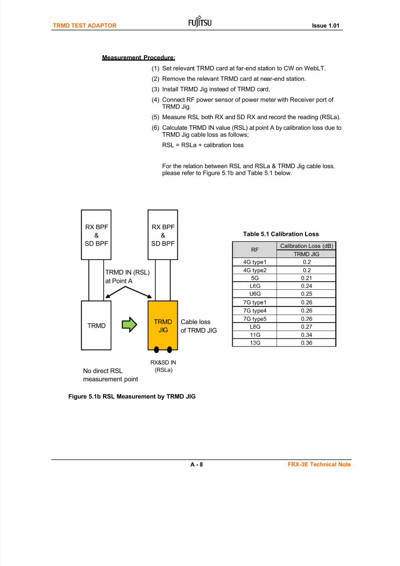
7/24/2019 Frx-3e Test v7.55 Issue1.06 June2014
http://slidepdf.com/reader/full/frx-3e-test-v755-issue106-june2014 212/214
TRMD TEST ADAPTOR Issue 1.01
FRX-3E Technical NoteA - 8
Measurement Procedure:
(1) Set relevant TRMD card at far-end station to CW on WebLT.
(2) Remove the relevant TRMD card at near-end station.
(3) Install TRMD Jig instead of TRMD card.
(4) Connect RF power sensor of power meter with Receiver port ofTRMD Jig.
(5) Measure RSL both RX and SD RX and record the reading (RSLa).
(6) Calculate TRMD IN value (RSL) at point A by calibration loss due toTRMD Jig cable loss as follows;
RSL = RSLa + calibration loss
For the relation between RSL and RSLa & TRMD Jig cable loss,
please refer to Figure 5.1b and Table 5.1 below.
Table 5.1 Calibration Loss
Figure 5.1b RSL Measurement by TRMD JIG
TRMD IN (RSL)
at Point A
Cable loss
of TRMD JIG
No direct RSL
measurement point
RX&SD IN
(RSLa)
RX BPF
&
SD BPF
TRMD
RX BPF
&
SD BPF
TRMD
JIG
4G type2 0.2
5G 0.21
RFTRMD JIG
4G type1 0.2
7G type1 0.26
7G type4 0.26
L6G 0.24
U6G 0.25
11G 0.34
13G 0.36
7G type5 0.26
L8G 0.27
Calibration Loss (dB)

7/24/2019 Frx-3e Test v7.55 Issue1.06 June2014
http://slidepdf.com/reader/full/frx-3e-test-v755-issue106-june2014 213/214
Issue1.01 TRMD TEST ADAPTOR
FRX-3E Technical Note A - 9
5.2 On-Site Transmitter Power Measurement
Measurement setup:
Figure 5.2a On-Site TX OUT Measurement Set-up
SD1 3 5 7
SDP 2 4 6
RX1 3 5 7
RXP 2 4 6
TX3 5 7
TXP 2 4 6
Power
Meter
TERM
Near-End Station Rack
AUXINTF
SV
BBINTF(W6)
BBINTF(W7)
BBINTF(P)
BBINTF(W1)
BBINTF(W2)
BBINTF(W3)
BBINTF(W4)
BBINTF(W5)
Install BPF JIG instead of
TX BPF unit and measure
TX power by power meter
Basic shelf
TR
MD(P)
TRMD(W1)
TRMD(W2)
TRMD(W3)
TRMD(W4)
TRMD(W5)
TRMD(W6)
TRMD(W7)
VEN T VEN T VEN T V EN T
TRADPT
TRADPT
TRADPT
TRADPT

7/24/2019 Frx-3e Test v7.55 Issue1.06 June2014
http://slidepdf.com/reader/full/frx-3e-test-v755-issue106-june2014 214/214
TRMD TEST ADAPTOR Issue 1.01
Measurement Procedure:
(1) Remove the relevant TX BPF unit at near-end station.
(2) Install BPF Jig instead of TX BPF unit.
(3) Connect high power RF attenuator and RF power sensor of powermeter with connector of BPF JIG.
(4) Measure TRMD RF power and record the reading (Pa).
(5) Calculate TRMD RF OUT value (Po) at point A’ by calibration lossdue to cable loss of BPF Jig and TRMD Adaptor (TRMD ADPT) asfollows;
Po = Pa + calibration loss of BPF Jig and TRMD ADPT
For the relation between Po and Pa & BPF Jig/TRMD ADPT cable