from lecture to realisation – timber (foot) bridges in
TRANSCRIPT
Footbridge 2014 5th International Conference Footbridges: Past, present & future
From lecture to realisation – timber (foot) bridges in Styria | Austria
as result of TU Graz education
Gerhard SCHICKHOFER Professor, Head of Institute Institute of Timber Engineering and Wood Technology Graz University of Technology Graz, Austria [email protected]
Andreas RINGHOFER Research and Teaching Assoc. Institute of Timber Engineering and Wood Technology Graz University of Technology Graz, Austria [email protected]
Georg FLATSCHER Research and Teaching Assoc. Institute of Timber Engineering and Wood Technology Graz University of Technology Graz, Austria [email protected]
Summary
Even though their span length is limited by material properties as well as their shape is limited by requirements subject to durability, well-designed timber footbridges can be impressive and aesthetic constructions. Motivated by that, we present four timber footbridge examples, which have been erected in the province of Styria (Austria) in the last two decades. Thereby, we not only focus on the main topics ‘deck construction’, ‘structural system’ and ‘constructive wood protection’, but also on the varying boundary conditions influencing the project’s realisation process. In major cases, civil engineering students educated at Graz University of Technology, especially by the Institute of Timber Engineering and Wood Technology, played an important role in this process. Finally and with regard to the projects presented, we summarise the major principles to be considered when designing timber footbridges.
Keywords: Timber footbridges; structural analysis; deck constructions; constructive wood protection; cross laminated timber
1. ‘Timber’ in research and teaching at Graz University of Technology
The Institute of Timber Engineering and Wood Technology as part of the Faculty of Civil Engineering in combination with the competence centre holz.bau forschungs gmbh is responsible for research and education activities in the science fields ‘timber engineering’ and ‘wood technology’ at Graz University of Technology (TU Graz). The major tasks of the institute can be divided up into four columns: ‘lignum_study’, ‘lignum_research’, ‘lignum_engineering’ and ‘lignum_test_center’ (LTC, accredited laboratory). Together with the holz.bau forschungs gmbh, which actually has nine shareholders (six from industry, two from science and one association) and Graz University of Technology as main owner, the institute is working on a four-year research programme (duration until 2016). The scientific staff includes 14 members all in all (partially PhD students and postdocs) and works with an total budget of approx. 1.2 Mio. € per year on the following topics:
‐ Timber Engineering (TE) – Design and Construction Sciences (DCS)
o Shell and Spatial Timber Constructions (SSTC)
o Innovative and Smart Connection Systems (ISCS)
o Assessment, Monitoring and Maintenance of ancient Timber Structures (AMTS)
‐ Wood Technology (TE) – Material and Structure Sciences (MSS)
o Material Modelling and Simulation Methods (MMSM)
o Advanced Products and Test Methods (APTM)
Parallel to the scientific activities mentioned above, courses in the bachelor (Civil Engineering Sciences with Environment and Construction Management) as well as in the master programme (Civil Engineering Sciences and Structural Engineering) are offered by the institute with main focus on the latter one (see Table 1). Thereby, basic skills in timber engineering are taught in the lectures ‘Building Materials Basics (part Wood Technology)’ and ‘Basics of Timber Engineering’. There is also the option to write the bachelor thesis in this discipline. Furthermore, students can complete

Footbridge 2014 – 5th International Conference - Footbridges: Past, present & future
and expand their knowledge in the context of various master courses as the requirements for the constructive block as shown in Table 1.
Table 1 Overview of bachelor and master courses offered by the Institute of Timber Engineering and Wood Technology at TU Graz
Programme Course ECTS Type
Bachelor Building Materials Basics (part Wood Technology) 0.5
Basic Skills Basics of Timber Engineering 4.0 Project (Bachelor) 5.0
Master
Timber Engineering 1 3.0
Completion and Expert Skills
Timber Engineering 2 3.0 Risk and Safety in Civil Engineering 3.0
Gluing Technology and Wood-based Materials 1.5 Assessment and Maintenance of Timber Structures 1.5
Structures in Timber 5.0 Construction Skills Timber Bridges 1.5
Wood Preservation 1.0 Timber and Forestry Economy 1.5
Practical Skills & Excursion
Practical Course 1 2.0 Practical Course 2 2.0
Excursion to Steel, Timber, Concrete and Composite Structures 1.0 Project (Master) 5.0 Master Thesis 30.0 Scientific Skills
PhD Research Seminar on Timber Engineering and Wood Technology 2.0 Scientific Skills
While the course ‘Timber Bridges’ is organised as a mix of theoretical and practical lectures (teacher-centred frontal instruction), ‘Structures in Timber’ follows the philosophy of the so-called principle of master classes. This means that up to thirty master students share the opportunity to work on real life projects in the frame of an intensive two-week blocked course, while teaching staff as well as additional lectors (engineers and architects from private companies) support them with their interdisciplinary expertise. In the following subsections we focus on these both courses in particular.
1.1 Master Course ‘Timber Bridges’
As shown in Table 1, ‘Timber Bridges’ is a course for master students and contains fifteen lectures (each 45 minutes), in which they acquire the special characteristics regarding the construction of timber bridges. Hereby, the identification of the main components of a timber bridge as well as their structural design, are regarded as the educational objectives of this course. Due to the fact that practical lectures alternate with theoretical ones, students also learn about the diversity of constructive details and how they are designed. The content of the associated script [1] with more than 300 pages includes the following items:
‐ Introduction: Modern contemporary timber bridges
‐ History of timber bridge construction
‐ Timber products and connection technique
‐ Wood protection
‐ Standards and guidelines
‐ Structural analysis of timber bridges
‐ Deck constructions
‐ Maintenance manual
‐ Master details
‐ Practical example: Structural design of a laterally pre-stressed slab bridge
Therefore, the main chapters are “Structural analysis of timber bridges” and “Deck constructions”. In the latter one, traditional as well as modern deck constructions are analysed extensively:

Footbridge 2014 – 5th International Conference - Footbridges: Past, present & future
“1.4 Deck constructions
Deck constructions contain the structural components of a deck, the waterproof seal and the road surface. Board systems – the traditional construction form (use of linear timber products, see Figure 1 left) – as well as slab systems – the modern construction form (use of planar timber products, see Figure 1 right) – can fulfil the major tasks of a deck construction.” [1]
Fig. 1 Comparison of traditional (left) and modern (right) deck constructions; according to [1]
Needless to say, both subjects, ‘deck constructions’ and ‘structural systems’, are key topics in the description of the timber footbridge examples given in section 2. In this publication, we define the structural system as the sum of all elements responsible for load bearing and transfer necessary to guarantee the structural safety of the construction. Depending on the bridge type, one or more tasks are fulfilled by one structural element:
‐ primary structure (PS)
The primary structure contains all the main bearing components of a bridge, which range from one abutment to the other, responsible for load transfer into the basements.
‐ secondary structure (SS)
The secondary structure contains cross beams and – if not part of the primary structure – suspenders and columns responsible for transfer of vertical loads from the bridge deck and/or the roof (traffic, snow).
‐ tertiary structure (TS)
The tertiary structure contains the deck construction and – if existing – the deck girders responsible for transfer of traffic loads to secondary and primary structure.
1.2 Master Course ‘Structures in Timber’
As mentioned in section 1.1 and as alternative to the usual teaching philosophy at TU Graz, master students work together in the context of a blocked interdisciplinary seminar which takes two weeks all in all. In chronological order this course is the last one offered by the Institute of Timber Engineering and Wood Technology in the master programme. Therefore, it is seen as a link between theory and practice combining engineering with architecture and, hence, could also be named: ‘From design (or ‘from an blank sheet’) to the construction’.
The course syllabus is quite simple: Eight to ten teams consisting of three to four students each have the choice to accept the challenge testing their theoretical skills and knowledge on a real life problem. Thereby, growing frustration
Footbridge 2014 – 5th International Conference - Footbridges: Past, present & future
based on missing know-how regarding the design process of a construction is guaranteed at the beginning of the course. The duty to brood over architectural design processes pushes the master students of Civil Engineering Science and Structural Engineering to their limits; they realize the difficult path architects have to go.
After a first intensive week of supervised teamwork including many failed design try-outs, the majority of the students is able to work out two or three good approaches to solve the problems. The final choice, which approach should be treated in detail is based on the outcome of a first presentation and a discussion with the whole class and supervisors. Consequently, the tasks of the second week are the further development of the chosen draft: considering locational boundary conditions when integrating the construction in the landscape; creating the structural design combined with constructive issues; selecting an adequate connection technique and structural detailing. Finally, all groups are evaluated by their supervisors in the course of presenting and discussing their projects in class. The timber footbridge projects described in section 2 underline the fact that those student drafts are not only theoretical ideas but also realised in some cases.
2. Timber footbridges in Styria
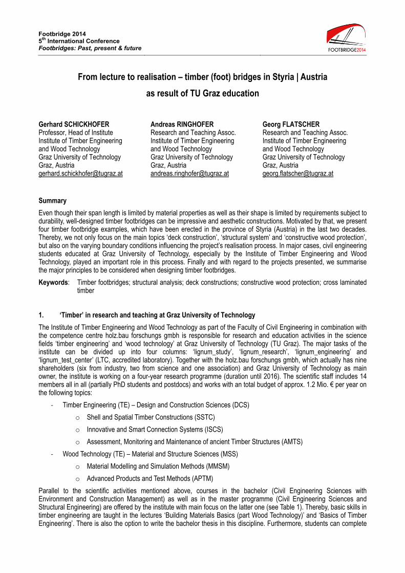
The realisation of the so-called ‘Holz-Europabrücke’ (‘European timber bridge’; structural analysis and design: G. Schickhofer, see Figure 2) in 1993 as well as the Styrian National Exhibition entitled ‘TimberTime’ in 1995 inaugurated the ‘Styrian epoch of timber bridges’. The formerly mentioned milestone project demonstrated the high performance of timber constructions and was a forerunner of a variety of timber bridges erected in Styria and in Austria in the upcoming years. The projects presented in the following subsections are an extract of this era having its highlights in the late nineties of the twentieth century.
Fig. 2 Impression of the ‘European timber bridge’
2.1 Project ‘Leonardo Bridge Fürstenfeld’, 1995
As mentioned before, in 1995 the Styrian National Exhibition entitled ‘TimberTime’ took place in the northern Styrian town ‘Murau’. In the course of the preparation for this event, a competition among students, young architects and civil engineers regarding the construction of a bridge called ‘Rantenbachsteg’ was organised and advertised by the Graz University of Technology in cooperation with the association ‘proHolz Steiermark’ in 1993. One of the submitted 34 projects was a system called ‘Leonardo Bridge’. Even though the project was not awarded, the concept awoke curiosity within the jury. One year later the idea of the bridge was realised in another Styrian village called ‘Großwilfersdorf’. Two further bridges using this system should follow, one in the eastern Styrian town ‘Fürstenfeld’ (1995) and another in the northern Styrian village ‘Katsch-Frojach’ (1996). The following impressions show the interesting bearing system on the basis of the footbridge erected in Fürstenfeld with a span length of 27 m.

Footbridge 2014 – 5th International Conference - Footbridges: Past, present & future
Fig. 3 Impressions of the timber footbridge ‘Leonardo Bridge’
Fig. 4 Technical drawings; above: elevation; left: detail; right: section A-A
As already implied by the name, the bridge concept follows a draft proposal made by Leonardo da Vinci in “Codex Atlanticus” (Folio 855), which can be interpreted as a certain form of a reverse trussed single-span system. However, the engineers realized that the idea of Leonardo da Vinci could be used in a more sufficient way if the structure was turned upside down. Only the low stiffness of the system was seen as a challenge. To avoid uneconomic cross sections, which may appear to be necessary to achieve the serviceability limit state, the bridge was pre-stressed by support displacement. In doing so, the primary structure, defined in section 1.2, only consists of the compression chords (GL24h, 2 x 160/300 mm) the steel braces (S355, Ø 40 mm and Ø 50 mm) and the columns (GL24h, 240/260 mm). Herein, the cross beams supporting the deck (GL24h, 220/300 mm) and the roof (GL24h, 220/220 mm double pinched) are regarded as the secondary structure. Consequently, the tertiary structure can be considered as the deck construction (mechanically jointed vertical boards, C24, h = 120 mm) as well as the roof (mechanically jointed vertical boards, C24, h = 80 mm) and the steel braces beneath the deck (S235, Ø 24 mm), which were also used to transfer the horizontal wind loads. As part of the bridge portal, steel rods finally transfer these loads from the roof to the abutment (S235, Ø 24 mm), see Figure 3. All timber elements were produced in larch (Larix decidua) excluding the deck and roof slab elements, which were made of Norway spruce (Picea abies).
As an essential detail of this bridge, the supporting situation has to be highlighted. As shown in Figure 4, the ‘rails’ on which the steel shoe is standing on, enable a smooth support displacement of 30 mm at each of the four portal columns by using a simple threaded rod. Furthermore, the higher stiffness of the bridge in winter, caused by the lower temperatures in comparison to the month of May when the bridge was mounted, allows the bridge a kind of intelligent reaction against the snow loads, see also [2].

Footbridge 2014 – 5th International Conference - Footbridges: Past, present & future
2.2 Project ‘Building Corridor Bad Gleichenberg’, 1996
In contrast to the other projects described in section 2, which are all parts of the public road network, the building corridor erected in a small eastern Styrian village called ‘Bad Gleichenberg’ in the year of 1996 connects two building blocks of the spa resort ‘Gleichenbergerhof’. The main reason making the structure out of timber, were the lower building costs compared to a solution in steel (see also [2,3]). Regarding its form and dimension, the construction is similar to a common timber footbridge and thus presented in this publication. Architectural design and structural analysis were done by ‘lignum_consult’ (group founded by former students of Graz University of Technology), production and mounting by the company ‘Buchacher’ (now part of the ‘Hasslacher Holding GmbH’).
Fig. 5 Impressions of the timber footbridge ‘Building Corridor Bad Gleichenberg’
Fig. 6 Technical drawings; top left: elevation; bottom left: cross section of the deck construction; right: section A-A
As shown in Figure 6, the corridor consists of two single-span truss girders with lengths of 19 and 5 meters as primary structure of this system. Due to topographic boundary conditions and the position of the building blocks, a bisection of the system was necessary leading to a bend in its orientation. The resulting intermediate support was designed as rigid portal frame against horizontal wind loads (see cross-section in Figure 6). The top and bottom chords as well as the columns of the truss girders are made of GL24h (with dimensions 160/160 mm and 160/144 mm) while steel rods (Ø 20 mm, Istor R55) serve as tension diagonals. In this context it is worth mentioning that the same doweled connection was used for all nodes of the primary structure (in order to avoid mistakes during assembly).
Figure 5 presents the corridor walls made of safety glass protecting the whole structure against water ingress caused by rainfall or snow. Consequently, there was no need to situate additional layers (waterproof surface) onto the glulam deck construction (GL24h) acting as tertiary structure of the system (linear multi-span girder). Thence, traffic loads – only caused by pedestrians – are transferred to cross beams (secondary structure) situated at the nodes of the truss girders. Besides bearing main vertical loads, the deck construction also serves as single-span bending beam in case of horizontal wind loads, which are partially transferred from the glass walls over the bottom chords into the cross beams

Footbridge 2014 – 5th International Conference - Footbridges: Past, present & future
and from there into the deck girder. In this context we want to point out the horizontal connection between cross beam and deck girder, realised by using a split ring connector (system ‘APPEL’) and by situating it in its centre axis, allowing free deformation caused by shrinkage and swelling of the timber. The second half of horizontal wind loads has to be carried by the truss system situated at roof level which components are the glulam top chords of the primary structure, steel braces and glulam posts (also GL24h).
2.3 Project ‘Raabsteg Feldbach’, 1998
The motivation to realise this footbridge project over the river Raab in the eastern Styrian town named ‘Feldbach’ was to connect a recently erected health centre with the urban road network in the year 1996. Therefore, while attending the course ‘Structures in Timber’ a group of master students developed three concepts : (i) a deck bridge in form of a fish-bellied girder, (ii) a king post truss bridge and (iii) a trussed plate girder bridge. Finally, the clients decided in favour of concept (iii), which consequently was built in 1998 by ‘Holzleimbau Stingl’ (production and mounting) in cooperation with ‘lignum_consult’ (architectural design and structural analysis).
Fig. 7 Impressions of the timber footbridge ‘Raabsteg Feldbach’
Fig. 8 Technical drawings; above: elevation; left and middle: detail; right: section A-A
The cross-section presented in Figure 8 displays two CLT (cross laminated timber, CL24 according to [4], t = 130 mm, 5 layered) - GLT (glued laminated timber, 200/350 and 200/450 mm, GL36c) plate girders in Norway spruce as main components of the primary structure, which can be assumed as an interlinked single-span system with a total span length of 35 m. The trussed girder (tension chord, 200/40 mm, S355) situated in the roof level is responsible for the main

Footbridge 2014 – 5th International Conference - Footbridges: Past, present & future
load bearing action (symmetric snow and traffic loads; load transfer through columns (120/120 mm, GL28h, larch) and suspenders (Ø 24 mm, Istor TX55) as secondary structure) while the deck girder has to bear asymmetric traffic loads and, in addition, significantly increases the system stiffness. Due to the combined CLT-GLT system in both roof and deck level, horizontal loads (wind loads perpendicular to the bridge axis, (minor) traffic loads in axial direction) are transferred by the in-plane acting CLT elements to the portal frames made of reinforced concrete. Consequently, no arrangement of horizontal bracing was necessary.
In the year 2000 the project won the Styrian award in timber engineering (category: public building). At the same time further research findings concerning cross-laminated timber (CLT) enabled the assessment of vibrations caused by pedestrians according to the (at that time) new ENV 1995-2 [5]. This procedure contained structural analysis using 3D beam analysis software (RM2000) as well as in-situ measures and was performed in the context of a diploma thesis at TU Graz, see [6]. According to this assessment the first vertical eigenfrequency resulted to f1,pred = 2.94 Hz (measured : f1,exp = 2.64 Hz), which is located in a range in which pedestrians are already negatively affected by vibrations. However, as a consequence of proper damping behaviour (δ = 0.043 at f1,exp = 2.64 Hz) the arrangement of vibration absorbers was not necessary.
The constructive wood protection as key aspect in the design of timber bridges was fulfilled by using a roof structure as well as a road surface as modern deck construction including asphalt combined with a waterproof protective coat. The only timber members affected by rainwater are the columns. Hence larch wood with a higher durability compared to Norway spruce was used.
2.4 Project ‘Truss Bridge Kindberg’, 2013
In 2013 the old ‘train-station-bridge’, connecting the centre of Kindberg, a small town to the north of the Styrian capitol Graz, and its train station by bridging the river Mürz, was replaced by a new one. In the context of the seminar ‘Structures in Timber’ in 2008, five concepts were designed by the participating students. After the seminar, two of those concepts, (plus a completely new one) were further developed in the context of master projects supervised by the institute (see Table 1). In the year 2009 the clients decided to realise the herein discussed truss bridge in a meeting by assessing the formerly mentioned drafts. Four years later, the bridge was built with minor adaptions compared to the students’ projects by ‘Kulmer Holzbau’ (production and mounting) in cooperation with ‘DI Helmut Stingl, Tragwerk Consulting Engineering’ (structural analysis).
Fig. 9 Impressions of the timber footbridge ‘Truss Bridge Kindberg’
Fig. 10 Elevation of the timber footbridge ‘Truss Bridge Kindberg’
Footbridge 2014 – 5th International Conference - Footbridges: Past, present & future
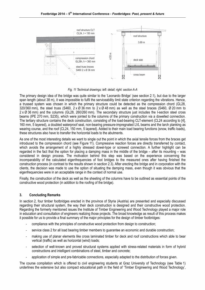
Fig. 11 Technical drawings; left: detail; right: section A-A
The primary design idea of the bridge was quite similar to the ‘Leonardo Bridge’ (see section 2.1), but due to the larger span length (about 38 m), it was impossible to fulfil the serviceability limit state criterion regarding the vibrations. Hence, a trussed system was chosen in which the primary structure could be detected as the compression chord (GL28, 320/360 mm), the steel truss (S460, 2 x Ø 36 mm to 2 x Ø 48 mm) as well as the steel braces (S460, Ø 20 mm to 2 x Ø 36 mm) and the columns (GL28, 260/260 mm). The secondary structure just includes the I-section steel cross beams (IPE 270 mm, S235), which were jointed to the columns of the primary construction via a dowelled connection. The tertiary structure contains the deck construction, consisting of the load-bearing CLT-element (CL24 according to [4], 160 mm, 5 layered), a doubled waterproof seal, non-bearing pressure-impregnated LVL beams and the larch planking as wearing course, and the roof (CL24, 150 mm, 5 layered). Added to their main load bearing functions (snow, traffic loads), these structures also have to transfer the horizontal loads to the abutments.
As one of the most interesting details we want to single out the point in which the axial tensile forces from the braces get introduced to the compression chord (see Figure 11). Compressive reaction forces are directly transferred by contact, which avoids the arrangement of a highly stressed dowel-type or screwed connection. A further highlight can be regarded in the fact that the option for placing a damping mass in the middle of the bridge – after its mounting – was considered in design process. The motivation behind this step was based on the experience concerning the incomparability of the calculated eigenfrequencies of foot bridges to the measured ones after having finished the construction process (in contrast to the results shown in section 2.3). After erecting the bridge and in corporation with the clients, the decision was made to use the option of situating the damping mass, even though it was obvious that the eigenfrequencies were in an acceptable range in the context of normal use.
Finally, the construction of the deck as well as the sheeting of the columns have to be outlined as essential points of the constructive wood protection (in addition to the roofing of the bridge).
3. Concluding Remarks
In section 2, four timber footbridges erected in the province of Styria (Austria) are presented and especially discussed regarding their structural system, the way their deck construction is designed and their constructive wood protection. Regarding the formerly mentioned issues the Institute of Timber Engineering and Wood Technology played a major role in education and consultation of engineers realizing those projects. The broad knowledge as result of this process makes it possible for us to provide a final summary of the major principles for the design of timber footbridges:
‐ compliance with the principles of constructive wood protection from design to construction;
‐ service class 2 for all load bearing timber members to guarantee an economic and durable construction;
‐ making use of planar elements like cross laminated timber for deck and roof constructions which able to bear vertical (traffic) as well as horizontal (wind) loads;
‐ selection of well-known and proved structural systems applied with stress-related materials in form of hybrid constructions and intelligent combinations of steel, timber and concrete;
‐ application of simple and pre-fabricable connections, especially adapted to the distribution of forces given.
The course compilation which is offered to civil engineering students at Graz University of Technology (see Table 1) underlines the extensive but also compact educational path in the field of ‘Timber Engineering and Wood Technology’,

Footbridge 2014 – 5th International Conference - Footbridges: Past, present & future
lasting from the bachelor to the PhD programme. Both courses ‘Timber bridges’ and ‘Structures in Timber’, focusing on the construction skills, follow the main objective to derive the students’ pleasure in design and construction. As a consequence of ‘learning-by-doing’, the ‘art of trying’ and the teamwork, students acquire the skills and self-assurance necessary to competently represent their solutions to their prospective clients.
4. Acknowledgements
Finally, we would like to acknowledge the following companies for supporting us with documents concerning the footbridge projects presented in section 2: ‘DI Helmut Stingl, Tragwerk Consulting Engineering’ and ‘Kulmer Bau GmbH’. Special thanks go to David Fruhmann for drawings, Architect Dr. Helmut Pierer for photographs and Gerald Raser and Reinhard Brandner for text corrections.
5. References
[1] SCHICKHOFER G., UNTERWIESER H., BERNASCONI A., “Brückenbau – Vorlesung”, Script related to the course “Timber Bridges” at Graz University of Technology, Graz, 2005.
[2] SCHICKHOFER G., “Holzbrücken in der Steiermark“, Architektur & Bau Forum, No. 4, 1996, pp. 67-81.
[3] SCHICKHOFER G., RIEBENBAUER J., “Der Projektvorschlag Holz hat überzeugt”, Schweizer Holzbau, No. 9, 1996, pp. 34-36.
[4] UNTERWIESER H., SCHICKHOFER G., “Characteristic Values and Test Configurations of CLT with Focus on Selected Properties”, COST FP1004 CLT Conference, Graz, 2013, pp. 53-74.
[5] CEN, “ENV 1995-2:1997 – Eurocode 5: Design of timber structures – Part 2: Bridges”.
[6] HEIDEN M., “Vergleich, Erläuterung und Anwendung der Europäischen Holzbrückenbaunorm ENV 1995-2/1997”, Diploma thesis, Graz University of Technology, Graz, 2000.