fracture analysis of particulate reinforced metal matrix ... · pdf...
TRANSCRIPT

James B. MinGlenn Research Center, Cleveland, Ohio
James A. CornieMetal Matrix Cast Composites, Inc., Waltham, Massachusetts
Fracture Analysis of Particulate ReinforcedMetal Matrix Composites
NASA/TM—2013-217871
May 2013
https://ntrs.nasa.gov/search.jsp?R=20130014832 2018-04-24T16:28:29+00:00Z

NASA STI Program . . . in Profi le
Since its founding, NASA has been dedicated to the advancement of aeronautics and space science. The NASA Scientifi c and Technical Information (STI) program plays a key part in helping NASA maintain this important role.
The NASA STI Program operates under the auspices of the Agency Chief Information Offi cer. It collects, organizes, provides for archiving, and disseminates NASA’s STI. The NASA STI program provides access to the NASA Aeronautics and Space Database and its public interface, the NASA Technical Reports Server, thus providing one of the largest collections of aeronautical and space science STI in the world. Results are published in both non-NASA channels and by NASA in the NASA STI Report Series, which includes the following report types: • TECHNICAL PUBLICATION. Reports of
completed research or a major signifi cant phase of research that present the results of NASA programs and include extensive data or theoretical analysis. Includes compilations of signifi cant scientifi c and technical data and information deemed to be of continuing reference value. NASA counterpart of peer-reviewed formal professional papers but has less stringent limitations on manuscript length and extent of graphic presentations.
• TECHNICAL MEMORANDUM. Scientifi c
and technical fi ndings that are preliminary or of specialized interest, e.g., quick release reports, working papers, and bibliographies that contain minimal annotation. Does not contain extensive analysis.
• CONTRACTOR REPORT. Scientifi c and
technical fi ndings by NASA-sponsored contractors and grantees.
• CONFERENCE PUBLICATION. Collected papers from scientifi c and technical conferences, symposia, seminars, or other meetings sponsored or cosponsored by NASA.
• SPECIAL PUBLICATION. Scientifi c,
technical, or historical information from NASA programs, projects, and missions, often concerned with subjects having substantial public interest.
• TECHNICAL TRANSLATION. English-
language translations of foreign scientifi c and technical material pertinent to NASA’s mission.
Specialized services also include creating custom thesauri, building customized databases, organizing and publishing research results.
For more information about the NASA STI program, see the following:
• Access the NASA STI program home page at http://www.sti.nasa.gov
• E-mail your question to [email protected] • Fax your question to the NASA STI
Information Desk at 443–757–5803 • Phone the NASA STI Information Desk at 443–757–5802 • Write to:
STI Information Desk NASA Center for AeroSpace Information 7115 Standard Drive Hanover, MD 21076–1320

James B. MinGlenn Research Center, Cleveland, Ohio
James A. CornieMetal Matrix Cast Composites, Inc., Waltham, Massachusetts
Fracture Analysis of Particulate ReinforcedMetal Matrix Composites
NASA/TM—2013-217871
May 2013
National Aeronautics andSpace Administration
Glenn Research CenterCleveland, Ohio 44135

Available from
NASA Center for Aerospace Information7115 Standard DriveHanover, MD 21076–1320
National Technical Information Service5301 Shawnee Road
Alexandria, VA 22312
Available electronically at http://www.sti.nasa.gov
Trade names and trademarks are used in this report for identifi cation only. Their usage does not constitute an offi cial endorsement, either expressed or implied, by the National Aeronautics and
Space Administration.
This work was sponsored by the Fundamental Aeronautics Program at the NASA Glenn Research Center.
Level of Review: This material has been technically reviewed by technical management.
NASA/TM—2013-217871 1
Fracture Analysis of Particulate Reinforced Metal Matrix Composites
James B. Min
National Aeronautics and Space Administration Glenn Research Center Cleveland, Ohio 44135
James A. Cornie
Metal Matrix Cast Composites, Inc. Waltham, Massachusetts 02453
Abstract
A fracture analysis of highly loaded particulate reinforced composites was performed using laser moire interferometry to measure the displacements within the plastic zone at the tip of an advancing crack. Ten castings were made of five different particulate reinforcement-aluminum alloy combinations. Each casting included net-shape specimens which were used for the evaluation of fracture toughness, tensile properties, and flexure properties resulting in an extensive materials properties data. Measured
fracture toughness range from 14.1 MPa m for an alumina reinforced 356 aluminum alloy to
23.9 MPa m for a silicon carbide reinforced 2214 aluminum alloy. For the combination of these K values and the measured tensile strengths, the compact tension specimens were too thin to yield true plane strain KIc values. All materials exhibited brittle behavior characterized by very small tensile ductility suggesting that successful application of these materials requires that the design stresses be below the elastic limit. Probabilistic design principles similar to those used with ceramics are recommended when using these materials. Such principles would include the use of experimentally determined design allowables. In the absence of thorough testing, a design allowable stress of 60 percent of the measured ultimate tensile stress is recommended.
Introduction
Metal matrix composites are being increasingly substituted in place of metals in a variety of applications. Such substitutions can be successful when the mechanical properties of such composites are adequately considered; however, the mechanical properties of composites are often poorly understood resulting in potentially unfavorable consequences.
Metal matrix composites can be made via numerous processing techniques. The advanced pressure infiltration casting (APIC) process (Ref. 1) was used for producing particulate-loaded composites. These materials, which typically have 40 to 70 percent of the particulate volume fraction, exhibit the behavior which lies between that of ceramics and that of metals. For example, APIC processed aluminum-alumina alloys have ultimate strengths equal to those of the base aluminum alloys, stiffness equal to those of cast iron or steel (at significantly less weight), yet minimal strains to failure. These same materials have fracture toughness, which are significantly below those of metals, yet 3 to 5 times greater than those of ceramics.
To facilitate the appropriate application of these composites, the current study was undertaken to first characterize the fracture behaviors and limiting strengths of APIC processed composites, and then to develop a design guide for the application of particulate-loaded metal matrix composites. The study was performed for the following three primary objectives to: (1) study the mode I fracture behavior of highly loaded particulate composites (Alumina, B4C, and SiC) by applying tensile loading to thin plates with single edge notch cracks, (2) develop a mechanical properties database for the above materials, and (3) set the groundwork for the development of a design guide with brittle composite materials.

NASA/TM—2013-217871 2
Materials and Methods
Central to the first two objectives stated above was the production and testing of eight combinations of aluminum alloy matrix and reinforcement.
Selection of Matrix Alloys
Aluminum alloys 356 and 2214 were chosen as the matrix alloys for all of the castings produced in this study. Their compositions are listed in Table 1. Alloy 2214 was chosen because fracture data are much needed. The alloy 356 Al-Si was chosen because mechanical property data are lacking for high silicon alloys.
Particulate composites based on the 520, 201, 295, and 2214 aluminum alloys were previously studied (Ref. 2). The constituents for these alloys are also listed in Table 1. These alloys are essentially Al-Mg, Al-Cu-Mg, Al-Cu-Si, and Al-Cu-Si-Mg alloys.
TABLE 1.—NOMINAL COMPOSITION OF MATRIX ALLOYS AND EXPECTED PRECIPITATING PHASES
Aluminum Cu Mg Si Precipitating phases Alloy Percent Percent Percent In matrix At internal interfaces 356 0.25 0.3 7.0 Si Al-Mg spinel, Si 2214 4.5 0.5 0.85 CuAl
2, Si Al-Mg spinel, CuAl
2, Si
520 0.25 10.0 0.25 Mg5Al
8 Al-Mg spinel, Mg5Al
8
201 4.6 0.55 0.1 CuAl2 Al-Mg spinel, CuAl
2
295 4.5 0.03 1.1 CuAl2, Si CuAl2, Si
To increase the strength of a discontinuously reinforced material, it is desirable to increase the strength of the matrix/particulate interface and the strength of the matrix. Increasing the interface strength also increases toughness; however, to increase bulk toughness the matrix alloy might have to be softened.
Each elemental addition has some effect in the matrix and at the internal interfaces. The addition of silicon has three potential strengthening effects. It can produce matrix strength through solid solution hardening and through precipitation hardening. It also leads to the precipitation of the silicon at reinforcement/matrix interfaces. In alumina reinforced systems the silicon precipitates will strongly adhere to the alumina and would therefore toughen the reinforcement interface. Similar effects might occur with other reinforcements.
Copper alloying additions can provide similar solid solution and precipitation strengthening; however, it also leads to the precipitation of the CuAl2 intermetallic at reinforcement/matrix interfaces. This precipitation is detrimental to the performance of particulate reinforced composites as CuAl2 debonds easily from alumina (Ref. 3).
Magnesium increases mechanical properties in several ways: it produces solid solution hardening, and it leads to the formation of an Al-Mg spinel which strongly adheres to alumina; and its precipitate, Mg5Al8, also strongly adheres to alumina. Regarding the aluminum-magnesium spinel layer on the reinforcement, it should be noted that this spinel forms in the liquid state during solidification and does not dissolve into the matrix during subsequent heat treatments. If anything, heat treatments would only increase the thickness of the spinel layer.
Aluminum-Silicon-Magnesium—356 Alloy
This alloy is essentially an aluminum—7 percent silicon with a small percentage of magnesium. In the alumina reinforced systems, the magnesium is expected to form magnesium-aluminum oxide spinel during casting by reaction of the melt with the reinforcement. This spinel is expected to strengthen the matrix-particle interface. The balance of the alloy (aluminum-silicon) should solidify as an eutectic structure. Heat treatment will result in spheroidal process of the dendrites and precipitation of silicon in the matrix, or at interfaces.

NASA/TM—2013-217871 3
Aluminum-Copper-Silicon-Magnesium—2214 Alloy
This alloy contains all three elements considered in this study. It was surmised that in alumina reinforced systems the magnesium would be largely consumed upon solidification due to the formation of the spinel. This would shift the matrix to the tertiary Al-Cu-Si system where there would be solid solution strengthening and precipitation hardening due to the presence of copper in the matrix and also precipitation strengthening of the interface due to silicon. We also expected interfacial CuAl2 precipitation during heat treatments. It is known that the copper solution and precipitation hardening greatly increases the strength of aluminum and provides versatility through heat treatment.
Aluminum-Magnesium—520 Alloy
This alloy is essentially Al-10% Mg. It was expected that in alumina reinforced systems the aluminum-magnesium spinel would form at the interfaces and there would be solid solution hardening in the matrix. Large amounts of Mg5Al8 were expected to form at the matrix/particulate interface upon heat treatment which would strongly adhere to the particulate.
Aluminum-Copper-Magnesium—201 Alloy
It was already known that CuAl2 does not strongly adhere to alumina; however, this detrimental influence on interfacial strength is only triggered after the long over-aging in the discontinuously coated interface (DCI) heat treatment. Addition of Mg is intended to offset this effect and to strengthen the interface after conditional heat treatments. This allows a variation in matrix yield strength in Cu rich alloys, from a peak at T6 condition described in Table 2 to a low after over-aging, without a concern for interface strength reduction.
Aluminum-Copper-Silicon—295 Alloy
Both the weakly adhering CuAl2 and the strongly adhering Si were expected to precipitate from this alloy. It was observed that alternating areas of strongly and weakly bonded precipitation has dramatically increased the toughness of continuously reinforced composites. This same mechanism might operate in particulate reinforced materials.
Selection of Ceramic Reinforcements
The pressure infiltration process (Ref. 4) allows a large variety of ceramic reinforcements to be incorporated into an aluminum matrix. A fundamental requirement is that the reinforcement must be thermodynamically compatible or non-reacting with molten aluminum. Many oxides and carbides satisfy this requirement. Although continuous or discontinuous reinforcements can be successfully pressure infiltrated, the low cost potential of the APIC process can be best realized with particulate reinforcements which allow the mold cavities to be filled by slurry processing.
The particulate reinforcements used in this study were alumina (Al2O3), boron carbide (B4C), and
silicon carbide (SiC) particulates. All of the particulates had a median particle size of nominally 15 m. The alumina particulate was a fused white alumina having the crystal structure. These particulates have characteristically strong shapes because during their manufacture they are milled causing the weakest particles to fracture. Although alumina particulate has a significant density impact, its low cost makes it an attractive reinforcement. Boron carbide particulate is of interest in weight sensitive applications, because it’s low density results in composites of lower density than that of the aluminum matrix. A drawback of B4C is its relatively high cost. Silicon carbide, SiC, is attractive because of its low density and high thermal conductivity. SiC with a “blocky” shape was chosen over the more acicular powders available to maximize fracture toughness of the composite. A standard, abrasive grade aluminum oxide

NASA/TM—2013-217871 4
(alundum), the above high purity aluminum oxide and the above “blocky” SiC particulates were used as reinforcements. The abrasive grade alumina (“Dark” alumina) was selected because of its relatively low cost. The high purity alumina (“White” alumina) was chosen for its strength and lower iron content. All powders were 15 µm average in diameter.
Selection of Heat Treatments
To improve their mechanical properties, each set of specimens cast in the current study was heat treated by solution heat-treating, water quenching and then artificially-aging to a T6 temper. The heat treating times and temperatures used for the 2214 and 356 alloys are given in Table 3.
The 356 alloy is a hypo-eutectic alloy containing 7 wt.% silicon and minor amounts of magnesium. The maximum solid solubility of silicon in aluminum is 1.65 wt.%; therefore, the heat treatment serves primarily to form spheroids of the eutectic structure. On the other hand, the copper present in the 2214 alloy is fully soluble at the solution temperature, and forms fine precipitates on aging.
All mechanical test specimens were heat treated to three conditions: T6, T7, or discontinuously coated interface (DCI) condition. The time and temperature for each condition is given in Table 2. T6 is the condition at which the matrix has peak hardness and theoretically peak strength. The T7 condition results in lower hardness in the alloy and possibly more ductility. Note that these heat treat times are shortened for the alloys selected. This is because the small inter-particle spacings in highly loaded composites greatly accelerate diffusion kinetics. These times, shown in Table 2, are based on highly loaded aluminum-224 alloys. The DCI treatment is a very over-aged condition at an intermediate temperature (between the age-hardening and homogenization temperatures) where intermetallic precipitates are easily formed at internal interfaces. These intermetallics may or may not be strongly adhering to the reinforcing material.
TABLE 2.—TIME AND TEMPERATURE INFORMATION FOR HEAT TREATMENTS OF MATRIX ALLOYS 201, 2214, 295, AND 520
Alloy T4 T6 T7 DCI 201 530 °C 24 hr,
water quench T4 followed by 160 °C 10 hr, air cool
T4 followed by 200 °C 4 hr, air cool
T7 followed by 350 °C 48 hr, air cool
2214 500 °C 24 hr, water quench
T4 followed by 170 °C 8 hr, air cool
T4 followed by 200 °C 4 hr, air cool
T7 followed by 350 °C 48 hr, air cool
295 515 °C 24 hr, water quench
T4 followed by 155 °C 10 hr, air cool
T4 followed by 200 °C 4 hr, air cool
T7 followed by 400 °C 48 hr, air cool
520 445 °C 24 hr, water quench
N/A T4 followed by 200 °C 4 hr, air cool
T7 followed by 350 °C 48 hr, air cool
TABLE 3.—TREATING TIMES AND TEMPERATURES FOR ALUMINUM ALLOYS 356 AND 2214
Solid solution heat treatment Artificial aging heat treatment Alloy Time,
hr Temperature,
°C Time,
hr Temperature,
°C 356 12 535 3.5 150
2214 12 502 8.0 170
NASA/TM—2013-217871 5
Design and Fabrication of Specimens
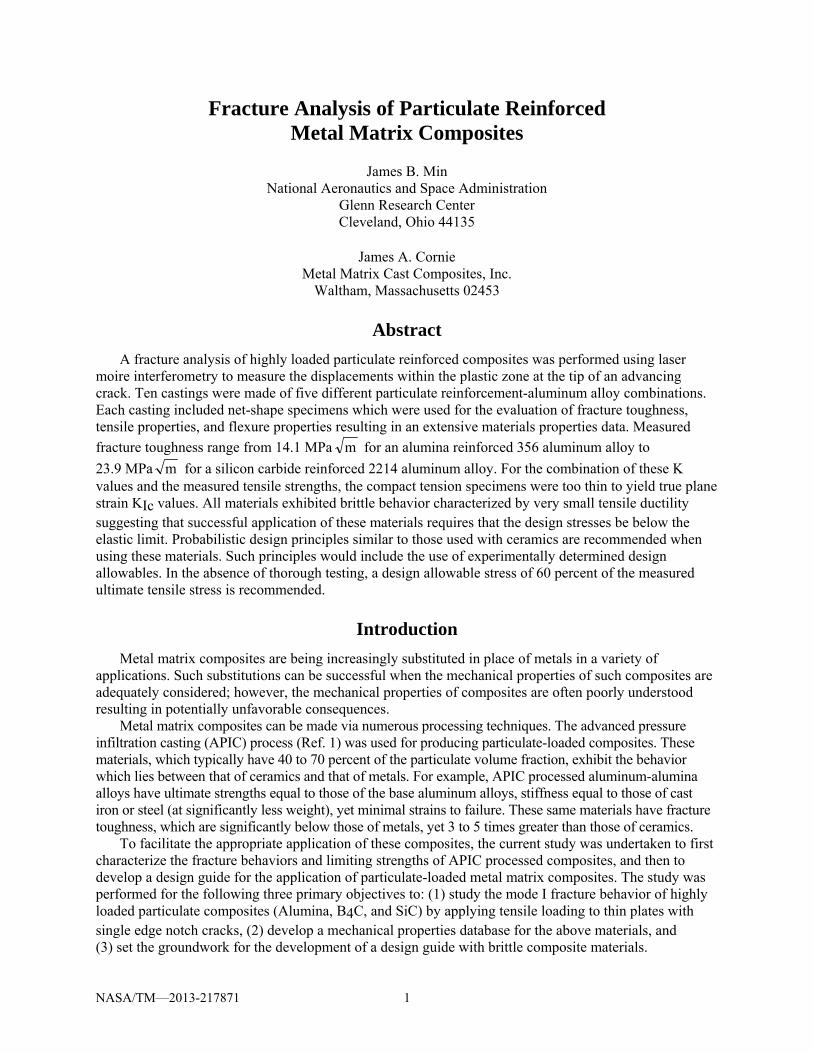
The fracture, tensile, and flexure properties of the materials were evaluated using appropriately designed specimens. The compact tension specimens, illustrated in Figure 1, were used to evaluate the Mode I fracture properties. Tensile coupons were flat dog-bones with gage sections 0.186 in. thick by 0.5 in. wide. The flexure bars had nominal 0.312 by 0.25 in. cross sections and 5 in. overall length. Mold cavities for the above specimens were designed and machined into graphite such that 3 compact tension specimens, 5 flat tensile specimens, 4 flexure bars, and 2 impact toughness specimens could be cast at one time. Figure 2 shows the mold cavities used to cast specimens. For each combination of alloy and reinforcement, the mold pack was filled with a slurry of the desired reinforcement, allowed to dry, placed into a mold vessel, outgassed, preheated in an inert atmosphere, covered with molten Al alloy, evacuated from beneath through a vent tube and pressure infiltrated with the desired alloy. The product of one such casting is shown in Figure 3. All test specimens were cast to net shape and tested without further machining, other than gate removal.
The APIC process allows net-shape castings to be made with accurate reproduction of detail. In this study, fracture specimens having a defined notch, tensile specimens, and flexure specimens suitable for mechanical testing were successfully cast.
The combinations of alloy and reinforcement cast are provided in Table 4. After casting, each set of specimens was removed from the graphite molds and then given the desired
heat treatment. Heat treating was done using a Blue M convection oven. Prior to mechanical testing all specimens were x-rayed to identify any casting defects.
Figure 1.—Sketch of single edge notched compact tension specimen.
Figure 2.—Graphite mold cavities used to cast test specimens.

NASA/TM—2013-217871 6
Figure 3.—Product of one casting showing three compact tension, five tensile, four flexure specimens,
and two ballistic specimens.
TABLE 4.—MATRIX ALLOY AND REINFORCEMENTS COMBINATIONS CAST
Matrix alloy Reinforcement 2214 Aluminum Alumina, Al2O3 (3 castings) 2214 Aluminum Boron carbide, B4C (2 castings) 2214 Aluminum Silicon carbide, SiC (2 castings) 356 Aluminum Alumina, Al2O3 356 Aluminum Boron carbide, B4C
Testing
The Mode I fracture testing was performed. Crack length, a, to specimen width, w, ratios (a/w) of 0.3 and 0.5 were used in testing. For an a/w ratio of 0.3, fatigue pre-cracks were generated at the root of the cast notches by cyclically loading the specimens. For an a/w ratio of 0.5, the cast notch was first extended by using a 0.3 mm wide diamond saw blade and then extended by fatiguing the specimen. The fatigue pre-cracks provide the necessary sharply- defined crack for accurate Mode I fracture testing. Moiré diffraction gratings were replicated on the surface of these specimens for measuring the two-dimensional deformation field using a four beam interferometer. The specimens were then loaded to failure while displacements, loads, and crack length were measured.
For tensile testing, loads measured with a load cell were recorded as function of strain which was measured using extensometer with 1.00 in. gage length. Crosshead speed was 0.05 in./min (1.27 mm/min) for an effective nominal strain rate of 510–4/sec. The ultimate stress and strain were of particular interest because minimal yielding as evidenced by yield point and plastic offset was observed.
Materials cast were tested in flexure using four point bending apparatus. The span between the two outer points was 103.6 mm and the cross head speed was 1.27 mm/min (0.05 in./min). Three point bend testing was also performed. For these tests the specimens were 6 by 8 mm in cross-section and 100 mm long. The span between the two outer points was 80 mm and cross head speed was 0.25 mm/min (0.01 in./min).

NASA/TM—2013-217871 7
Results
Casting
Ten castings were made with the materials listed in Table 4. All but one of the castings resulted in usable test specimens and eight of the castings were free of significant defects. One of the boron carbide reinforced 2214 aluminum castings was improperly loaded with the ceramic slurry resulting in unreinforced sections in two of the compact tension specimens. Because these defects were distant from the crack plane, these samples were allowed for testing. The first silicon carbide reinforced 2214 aluminum casting exhibited severe inhomogeneity in reinforcement distribution and these materials were judged to be unsuitable for testing.
Tensile Testing
The results of tensile tests on the five materials cast (Table 4) are tabulated below in Table 5. Each value is the average of four to six experimental values. The elastic moduli of particulate-reinforced composites, 173 to 202 GPa, are approaching or equal to those of steel and cast iron, and significantly greater than the 72 GPa value of 2214 aluminum (Ref. 5). The very low failure strains of 0.12 to 0.19 percent indicate an almost complete lack of plasticity.
The measured ultimate tensile strengths of the composites with the 2214 aluminum alloy matrix ranging from 224 to 328 MPa are less than the 483 MPa reported for the unreinforced 2214. This is not uncommon of particulate composites wherein the particulates neither carry the load nor block dislocation movement on a fine scale. Three casting of alumina reinforced 2214 were made and tested. Castings 1 and 3 had very similar strengths, 325 and 328 MPa, while casting 2 had a considerably lower strength, 224 MPa. This might be due to differences in heat treatment (operator error) or in alloy composition. This latter seems unlikely, as the melt stock for all of the 2214 castings was a single lot of pre-alloyed ingots.
Two castings were made with 356 aluminum alloy matrices. These exhibited ultimate strengths of 270 and 226 MPa. The data in Table 5 appear to indicate that the alumina reinforced aluminum composites are generally stronger than those reinforced with boron carbide or silicon carbide; however, further testing would be required to arrive at a statistically valid conclusion. It should be expected that matrix alloys could be similarly optimized for either silicon carbide or boron carbide reinforcements.
TABLE 5.—TENSILE PROPERTIES OF CAST Al PARTICULATE-REINFORCED COMPOSITES Aluminum alloy—
reinforcement Ultimate tensile strength,
MPa Failure strain,
percent Elastic modulus,
Gpa 2214—Alumina Casting 1
328 0.152 202
2214—Alumina Casting 2
224 0.122 191
2214—Alumina Casting 3
325 not measured not measured
2214—Boron carbide Casting 1
318 0.190 189
2214—Boron carbide Casting 2
284 0.178 173
2214—Silicon carbide Casting 2
280 not measured not measured
356—Alumina 270 not measured not measured 356—Boron carbide 226 not measured not measured

NASA/TM—2013-217871 8
Flexure Testing
The strength values of rupture determined in flexure tests on four materials cast are tabulated in Table 6. For comparison the ultimate tensile strengths shown in Table 5 are repeated in this table. The rupture strength values show a strong correlation with the ultimate tensile strengths and are typically 60 percent higher than the ultimate tensile strengths.
The results of flexure testing are shown in Table 7. In this study flexure strength was determined through a three-point bend test (Ref. 6). The specimens were 6 by 8 mm in cross-section and 100 mm long. Each data point is the average of four tests.
TABLE 6.—RUPTURE STRENGTH FOR CAST Al PARTICULATE-REINFORCED COMPOSITES Aluminum alloy reinforcement Rupture tensile strength,
MPa Ultimate tensile strength,
MPa 2214—Alumina Casting 1
Not measured 328
2214—Alumina Casting 2
Not measured 224
2214—Alumina Casting 3
530 325
2214—Boron carbide Casting 1
Not measured 318
2214—Boron carbide Casting 2
Not measured 284
2214—Silicon carbide Casting 2
427 280
356—Alumina 422 270 356—Boron carbide 377 226
TABLE 7.—FLEXURE STRENGTH OF COMPOSITE TEST SPECIMENS Flexure strength, MPa
Alloy Reinforcement Heat treatment T6 T7 DCI
520 White Alumina Dark Alumina SiC
--- --- ---
472 442 367
653 527 360
201 White Alumina Dark Alumina SiC
573 561 561
507 457 458
450 413 ---
295 White Alumina Dark Alumina SIC
573 561 561
507 457 458
450 413 ---
2214 White Alumina Dark Alumina SIC
656 550 503
529 ---
379
470 427 353
Plane Strain Fracture Toughness, KIc, Testing
Testing and data analysis were performed on two compact tension specimens. The data from these tests are provided in Table 8. The apparent plain strain fracture toughness, KIc, values are 16.09 and 22.36 MPa √m for the first and second castings of alumina reinforced 2214 aluminum, respectively. Both of these values are unusually high for highly loaded aluminum matrix composites.

NASA/TM—2013-217871 9
TABLE 8.—LOAD VERSUS CRACK EXTENSION DATA FOR PLAIN STRAIN FRACTURE TOUGHNESS TESTS
Alumina—2214 Aluminum composite, first casting a/w = 0.3
Load, KN
∆a, mm
Global K, MPa √m
2.5 0.96 7.88 2.8 0.96 8.83 3.2 1.09 10.15 3.5 1.16 11.13 3.8 1.26 12.14 4.1 1.29 13.12 4.4 1.43 14.16 4.7 1.69 15.31
Pmax = 4.93 KN
KIc = 16.09 MPa √m
Alumina—2214 Aluminum composite, second casting
a/w = 0.5 Load, KN
∆a, mm
Global K, MPa √m
1.1 0.19 7.2 1.4 0.237 9.18 1.7 0.261 11.17 2.0 0.309 13.17 2.3 0.38 15.19 2.6 0.38 17.17 2.9 0.523 19.29 3.2 0.594 21.36
Pmax = 3.35 KN
KIc = 22.36 MPa √m
These high KIc values are likely due to incorrect specimen geometry. All of the compact tension specimens cast in this analysis were 6.35 mm (0.25 in.) thick. In order to get an accurate measure of the plane strain fracture toughness, the specimen thickness should be a multiple of the plastic zone size which is related to (KIc/ys)
2 where ys is yield stress. The ASTM specification requires that the specimen thickness, B, be no less than 2.5 * (KIc /ys)
2. For the measured values of ultimate tensile strength and KIc, minimum specimen thicknesses of 5.9 mm (0.23 in.) and 24.9 mm (0.98 in.) would be required for accurate plain strain fracture toughness. In the future studies, thicker specimens will be cast and evaluated.
The second plane strain fracture toughness value may also be erroneously high because a sufficiently long pre-crack could not be grown in fatigue. This would result in a crack tip which was effectively blunter than desirable. A blunt crack tip would reduce the magnitudes of the stress fields at the crack tip; thereby, allowing higher loads to be carried for a given crack length.
In spite of the short comings in specimen geometry, the results should provide valuable insight into the fracture behavior of particulate-loaded aluminum-matrix composites.
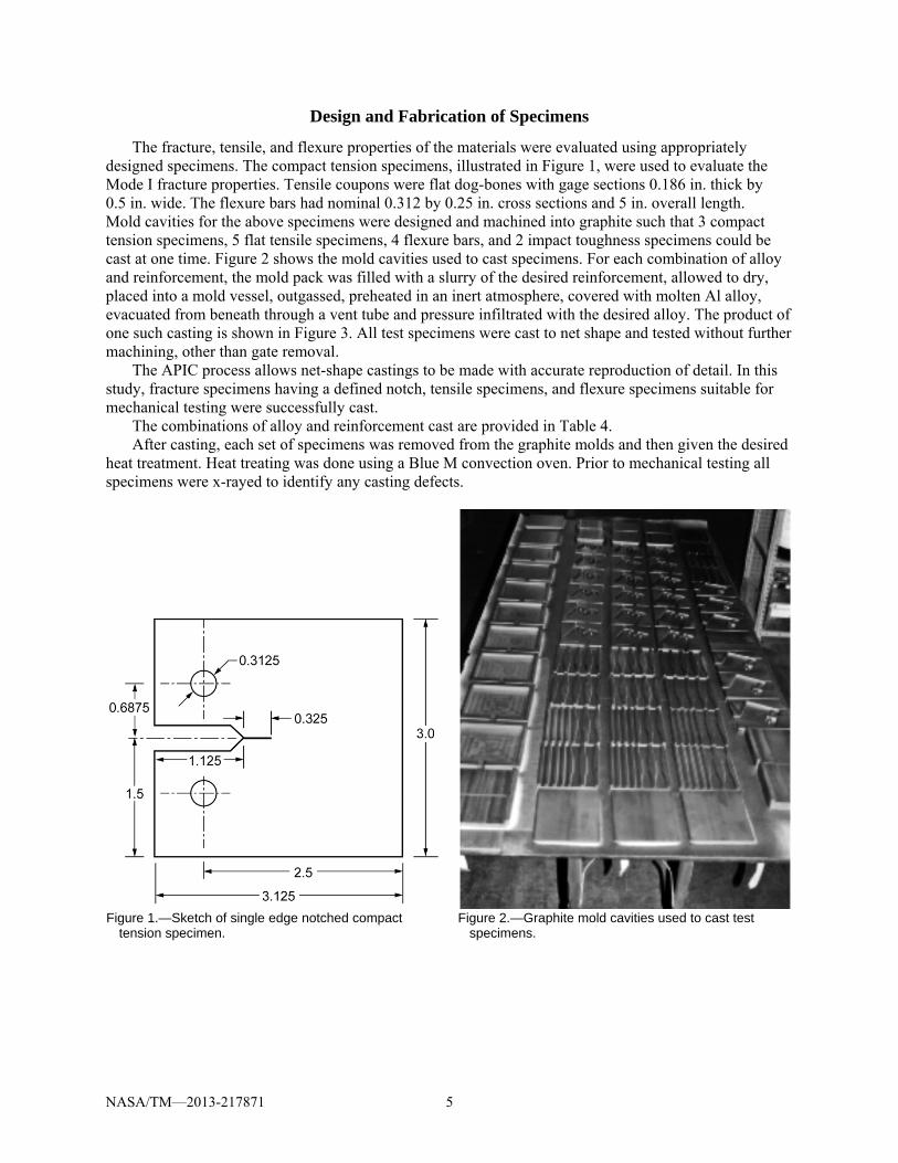
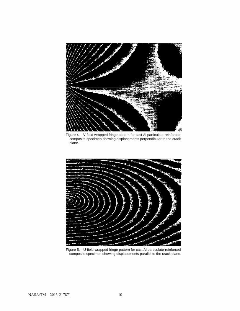
Moiré interferometry (Ref. 7) was also employed to perform fracture studies. Laser Moiré interferometry is a unique surface deformation analysis tool that can image the propagation of stress waves in real time and analyze the evolution of the fracture event in-situ. Figure 4 is a V-field image which shows the displacements perpendicular to the crack plane, where numerous steps were required to extract displacement and strain fields from the photographs of the specimens in X, Y and Z locations, U, V and W displacements and strains. Each fringe is a contour of constant displacement and corresponds to a displacement of 0.43 mm. Figure 5 is a U-field image which shows the displacements parallel to the crack plane. Again each fringe corresponds to a displacement of 0.43 mm. Analysis of these displacement fields enabled the quantification of the plastic zone size and the effects of the particulate on the stress fields within the plastic zone.
NASA/TM—2013-217871 10
Figure 4.—V-field wrapped fringe pattern for cast Al particulate-reinforced
composite specimen showing displacements perpendicular to the crack plane.
Figure 5.—U-field wrapped fringe pattern for cast Al particulate-reinforced
composite specimen showing displacements parallel to the crack plane.

NASA/TM—2013-217871 11
TABLE 9.—MEASURED FRACTURE TOUGHNESS VALUES, KQ, OF CAST
ALUMINUM PARTICULATE-REINFORCED COMPOSITES USING LASER MOIRÉ INTERFEROMETRY METHOD
Aluminum alloy—Reinforcement Fracture Toughness, KQ, MPa √m
2214—alumina Casting 1
16.1
2214—alumina Casting 2
22.4
2214—alumina Casting 3
17.7
2214—boron carbide Casting 1
To be measured
2214—boron carbide Casting 2
To be measured
2214—silicon carbide Casting 2
23.9
356—alumina 17.8 356—boron carbide 14.1
TABLE 10.—FRACTURE TOUGHNESS OF COMPOSITE TEST SPECIMENS
USING THREE POINT BENDING METHOD Fracture toughness, MPa√m
Alloy Reinforcement Heat treatment T6 T7 DCI
520 White Alumina Dark Alumina
---- ----
10.9 9.01
10.9 8.51
201 White Alumina Dark Alumina
9.75 ----
9.19 9.99
9.01 8.78
295 White Alumina Dark Alumina
8.96 10.9
---- 10.2
9.25 9.71
2214 White Alumina Dark Alumina
11.7 10.9
11.7 11.4
10.1 8.95
Specimens from four of the castings were tested with as cast geometry, i.e., without generating a
fatigue pre-crack. Acknowledging that these specimens were thinner than adequate, the results are provided in Table 9 as KQ values, where KQ is critical fracture toughness measured.
Additionally the plane strain fracture properties of aluminum matrix composites were evaluated using a three point bending method. These fracture toughness tests followed ASTM Standard (Ref. 7). This set-up involved a span of 80 mm and strain was measured through attached knife edge gauge arms. Specimen size was 20 by 10 by 90 mm. Cross head speed was 0.01 in./min. Fracture toughness results are listed in Table 10. Each data point is the average of three tests.
Charpy Impact Toughness
An evaluation of the impact toughness was conducted according to ASTM Standard (Ref. 9). Specimens were 6 by 8 by 55 mm and were un-notched. Pendulum distance to the center of strike was 720 mm and the supporting force was 1722.3 g. Impact toughness results are detailed in Table 11. Each data point is the average of four tests.

NASA/TM—2013-217871 12
TABLE 11.—CHARPY IMPACT TOUGHNESS OF COMPOSITE TEST SPECIMENS
Charpy impact toughness, KJ/M2 Alloy Reinforcement Heat treatment
T6 T7 DCI
520 White Alumina ---- 22.8 22.0 Dark Alumina ---- 22.9 22.6
SiC ---- 8.97 9.53
201 White Alumina 15.5 19.7 20.6 Dark Alumina 19.4 18.1 25.4
SiC 11.6 11.0 10.2
295 White Alumina 14.9 12.5 14.2 Dark Alumina 21.7 21.7 27.3
SiC 10.5 9.35 11.6
2214 White Alumina 21.4 10.8 23.6 Dark Alumina 19.6 22.1 27.4
SiC 15.9 11.3 18.2
Summary and Discussion
The current fracture analysis provides mechanical property data for a large number of particulate reinforced aluminum-matrix composites produced by the net-shape casting process.
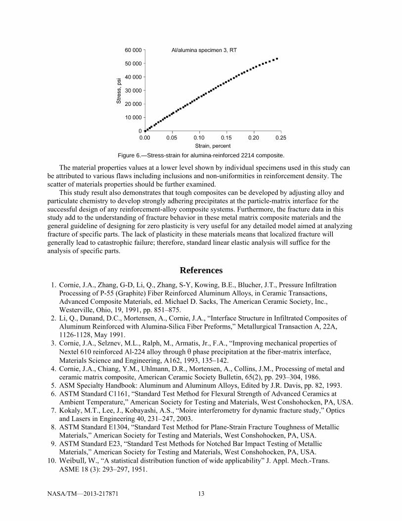
The data show that these materials possess attractive elastic properties and good tensile strengths; however, they possess an inherent lack of plasticity which leads to failure once yielding begins. This behavior is illustrated in the stress strain plot shown in Figure 6 and by the low strain to failure values in Table 5. The total strain is very small, and the elastic (linear) strain is a significant fraction of the total strain. The onset of plasticity, marked by the departure from linearity leads quickly to failure.
Successful application of these materials in engineered systems will require that this lack of plasticity be considered when designing with metal matrix composites. Specifically, we suggest that localized stress or general plastic flow be avoided. This differs from design with traditional metallic alloys where some localized stress flow may occur at regions of stress risers or part geometry. Localized stress flow in metals results in redistribution of the stresses with an accompanying reduction in peak stresses. In composites, such stress reduction through localized stress flow is not possible. Instead any highly localized stresses will result in localized failure initiation with subsequent propagation through the material. The results of this study suggest that when designing with metal matrix composites the stresses should be below the elastic limit.
Designing at or below the elastic limit allows linear elasticity methodology to be applied when designing with these composites. This opens the door to the use of less complicated linear elastic fracture mechanics (LEFM) finite element methods (FEM) or even simple textbook closed-form solutions for analyzing the fracture behaviors of these composite materials.
The material values provided in Table 5 are the average of 4 to 6 test results having a statistical scatter. Owing to the catastrophic failure mode of these materials, it would be required that probabilistic design principles, including Weibull statistics (Ref. 10), are considered. In this study six or fewer specimens of each material were evaluated for each mechanical property. Adequate probabilistic assessment would require testing approximately thirty samples. These same principles have long been applied to design with structural ceramics which possess similar brittleness, but far less fracture toughness. Such testing data could allow the determination of appropriate design allowables at which no failure should occur. As a rule of thumb, we would suggest that setting the maximum allowable stress at 60 percent of the ultimate tensile stress should suffice. For all of the tensile tests covered by this study (approximately 110), only five specimens would fail at stress of 60 percent of the ultimate tensile strength measured.
NASA/TM—2013-217871 13
Figure 6.—Stress-strain for alumina-reinforced 2214 composite.
The material properties values at a lower level shown by individual specimens used in this study can be attributed to various flaws including inclusions and non-uniformities in reinforcement density. The scatter of materials properties should be further examined.
This study result also demonstrates that tough composites can be developed by adjusting alloy and particulate chemistry to develop strongly adhering precipitates at the particle-matrix interface for the successful design of any reinforcement-alloy composite systems. Furthermore, the fracture data in this study add to the understanding of fracture behavior in these metal matrix composite materials and the general guideline of designing for zero plasticity is very useful for any detailed model aimed at analyzing fracture of specific parts. The lack of plasticity in these materials means that localized fracture will generally lead to catastrophic failure; therefore, standard linear elastic analysis will suffice for the analysis of specific parts.
References
1. Cornie, J.A., Zhang, G-D, Li, Q., Zhang, S-Y, Kowing, B.E., Blucher, J.T., Pressure Infiltration Processing of P-55 (Graphite) Fiber Reinforced Aluminum Alloys, in Ceramic Transactions, Advanced Composite Materials, ed. Michael D. Sacks, The American Ceramic Society, Inc., Westerville, Ohio, 19, 1991, pp. 851–875.
2. Li, Q., Dunand, D.C., Mortensen, A., Cornie, J.A., “Interface Structure in Infiltrated Composites of Aluminum Reinforced with Alumina-Silica Fiber Preforms,” Metallurgical Transaction A, 22A, 1126-1128, May 1991.
3. Cornie, J.A., Selznev, M.L., Ralph, M., Armatis, Jr., F.A., “Improving mechanical properties of Nextel 610 reinforced Al-224 alloy through θ phase precipitation at the fiber-matrix interface, Materials Science and Engineering, A162, 1993, 135–142.
4. Cornie, J.A., Chiang, Y.M., Uhlmann, D.R., Mortensen, A., Collins, J.M., Processing of metal and ceramic matrix composite, American Ceramic Society Bulletin, 65(2), pp. 293–304, 1986.
5. ASM Specialty Handbook: Aluminum and Aluminum Alloys, Edited by J.R. Davis, pp. 82, 1993. 6. ASTM Standard C1161, “Standard Test Method for Flexural Strength of Advanced Ceramics at
Ambient Temperature,” American Society for Testing and Materials, West Conshohocken, PA, USA. 7. Kokaly, M.T., Lee, J., Kobayashi, A.S., “Moire interferometry for dynamic fracture study,” Optics
and Lasers in Engineering 40, 231–247, 2003. 8. ASTM Standard E1304, “Standard Test Method for Plane-Strain Fracture Toughness of Metallic
Materials,” American Society for Testing and Materials, West Conshohocken, PA, USA. 9. ASTM Standard E23, “Standard Test Methods for Notched Bar Impact Testing of Metallic
Materials,” American Society for Testing and Materials, West Conshohocken, PA, USA. 10. Weibull, W., “A statistical distribution function of wide applicability” J. Appl. Mech.-Trans.
ASME 18 (3): 293–297, 1951.

REPORT DOCUMENTATION PAGE Form Approved OMB No. 0704-0188
The public reporting burden for this collection of information is estimated to average 1 hour per response, including the time for reviewing instructions, searching existing data sources, gathering and maintaining the data needed, and completing and reviewing the collection of information. Send comments regarding this burden estimate or any other aspect of this collection of information, including suggestions for reducing this burden, to Department of Defense, Washington Headquarters Services, Directorate for Information Operations and Reports (0704-0188), 1215 Jefferson Davis Highway, Suite 1204, Arlington, VA 22202-4302. Respondents should be aware that notwithstanding any other provision of law, no person shall be subject to any penalty for failing to comply with a collection of information if it does not display a currently valid OMB control number. PLEASE DO NOT RETURN YOUR FORM TO THE ABOVE ADDRESS.
1. REPORT DATE (DD-MM-YYYY) 01-05-2013
2. REPORT TYPE Technical Memorandum
3. DATES COVERED (From - To)
4. TITLE AND SUBTITLE Fracture Analysis of Particulate Reinforced Metal Matrix Composites
5a. CONTRACT NUMBER
5b. GRANT NUMBER
5c. PROGRAM ELEMENT NUMBER
6. AUTHOR(S) Min, James, B.; Cornie, James, A.
5d. PROJECT NUMBER
5e. TASK NUMBER
5f. WORK UNIT NUMBER WBS 473452.02.03.01.05
7. PERFORMING ORGANIZATION NAME(S) AND ADDRESS(ES) National Aeronautics and Space Administration John H. Glenn Research Center at Lewis Field Cleveland, Ohio 44135-3191
8. PERFORMING ORGANIZATION REPORT NUMBER E-18668
9. SPONSORING/MONITORING AGENCY NAME(S) AND ADDRESS(ES) National Aeronautics and Space Administration Washington, DC 20546-0001
10. SPONSORING/MONITOR'S ACRONYM(S) NASA
11. SPONSORING/MONITORING REPORT NUMBER NASA/TM-2013-217871
12. DISTRIBUTION/AVAILABILITY STATEMENT Unclassified-Unlimited Subject Categories: 05, 16, and 39 Available electronically at http://www.sti.nasa.gov This publication is available from the NASA Center for AeroSpace Information, 443-757-5802
13. SUPPLEMENTARY NOTES
14. ABSTRACT A fracture analysis of highly loaded particulate reinforced composites was performed using laser moire interferometry to measure the displacements within the plastic zone at the tip of an advancing crack. Ten castings were made of five different particulate reinforcement-aluminum alloy combinations. Each casting included net-shape specimens which were used for the evaluation of fracture toughness, tensile properties, and flexure properties resulting in an extensive materials properties data. Measured fracture toughness range from 14.1 MPa for an alumina reinforced 356 aluminum alloy to 23.9 MPa for a silicon carbide reinforced 2214 aluminum alloy. For the combination of these K values and the measured tensile strengths, the compact tension specimens were too thin to yield true plane strain KIc values. All materials exhibited brittle behavior characterized by very small tensile ductility suggesting that successful application of these materials requires that the design stresses be below the elastic limit. Probabilistic design principles similar to those used with ceramics are recommended when using these materials. Such principles would include the use of experimentally determined design allowables. In the absence of thorough testing, a design allowable stress of 60 percent of the measured ultimate tensile stress is recommended.15. SUBJECT TERMS Fracture mechanics; Particulate reinforcement-aluminum alloy; Metal matrix composites; Finite element; Plastic zone; Design allowable stress 16. SECURITY CLASSIFICATION OF: 17. LIMITATION OF
ABSTRACT UU
18. NUMBER OF PAGES
20
19a. NAME OF RESPONSIBLE PERSON STI Help Desk (email:[email protected])
a. REPORT U
b. ABSTRACT U
c. THIS PAGE U
19b. TELEPHONE NUMBER (include area code) 443-757-5802
Standard Form 298 (Rev. 8-98)Prescribed by ANSI Std. Z39-18

