fracture mechanics of nano-silica particles in reinforced epoxies
TRANSCRIPT

1 Copyright © 2009 by ASME
Proceedings of the Final Report MAE551
Fall 2014, Miami, Florida, USA
MODELING THE FRACTURE MECHANICS OF NANO-SILICA PARTICLE AGGLOMERATIONS IN REINFORCED EPOXIES
Jordan Suls University of Miami
McArthur Engineering Building, Coral Gables, FL 33146
Abstract
This study aimed at examining the fracture mechanics of nanosilica particle agglomeration in an epoxy matrix using extended finite element method (XFEM). The goal was determine the affects of clumping on the fracture toughness and energy of reinforced epoxies through the use of simulation in Abaqus. Three models of various particle dispersion levels were used to analyze the rate of crack propagation through the material to quantify the importance of particle dispersion. The three, notched specimens were subjected to Mode 1 tensile loading. The results found were that the evenly dispersed model had the greatest fracture toughness, shown by the ability to handle a greater force at similar displacements. This result is mostly due to the fact that a large stress region developed in the clumped region. This stress caused the interface between the particle and matrix to debond which decreased the ability of the material to deflect the crack. Introduction Epoxy resins have a wide range of applications, including as an adhesive, coating or matrix for a composite material. Cured epoxies are amorphous,
thermosetting polymers, which allows for them to posses useful properties such as a high modulus and failure strength, low creep and good performance at higher temperatures [1]. Despite this, the brittle nature of epoxy resins make it necessary for the inclusion of toughening agents to increase the resistance to fracture. An improved toughness is becoming increasingly important for structural materials. The ability to absorb energy upon impact is crucial in the design of automobiles, trains, aircraft, etc. Typically metals are used due to their ability to absorb energy as they plastically deform. By including nanoparticles into a polymer, the material is able exhibit energy absorption in the form of internal damping and increased fracture toughness. For this, there are two sets of toughening materials that can be applied to improve the toughness of the epoxy resin: low modulus rubber particles or high modulus hard particles [2]. The rubber particles are capable of dissipating energy at the crack tip but lead to a decrease in the modulus and thermal properties of the resin. In contrast, the hard particles can properly improve the toughness of the resin through the mechanisms of energy dissipation such as crack-path deflection, particle debonding, microcracking, crack bridging, etc.
2 Copyright © 2009 by ASME
without sacrificing the modulus and thermal properties [2].
Traditionally, the inorganic ceramic particles introduced into the matrix were in the micro size range. These relatively large sized particles would hinder the processing ability of the material by significantly increasing the viscosity of the resin [1]. Similarly, as a load is placed on the material, microcracks can form between silica layers or the weak epoxy-particle interface can become debonded [3]. The size of the particles increases the likelihood of the phase separation of the particle from the matrix, which limits the performance of the material [4].
More recent research explores the addition of nano-sized silica particles into epoxies. The theory behind the advantages of nanoparticles is that they act as part of the microstructure and the interfacial interactions produce the new, enhanced material toughness while not increasing the resin’s viscosity. The nanoparticles presence help suppress the mobility of polymer chain at the particle surface interface. The smaller particles allow for a greater contact surface area between the particle and epoxy while maintaining the same volume fraction [2]. Several parameters are considered and investigated when attempting to determine the role of the nanoparticles on the fracture mechanics of the material. The main factors that affect the properties of the nanocomposite are the dispersion, dimensions, volume fraction, matrix material and the interfacial interaction between the particle and matrix [4]. This study will focus on the influence the dispersion can have on the fracture toughness of the reinforced epoxy matrix.
Typically, an even dispersion of nanoparticles is desired to achieve the enhanced toughness. To obtain a homogenous dispersion, some techniques used to deagglomerate particles are mechanical mixing using shear forces or applying ultrasound vibrations [5].
Despite the presence of these methods, the issue of particle clumping is still one that is run into by researchers. The affects of agglomerations are still relatively unknown. Boesl et al. [6] theorized that the presence of a particle agglomeration is
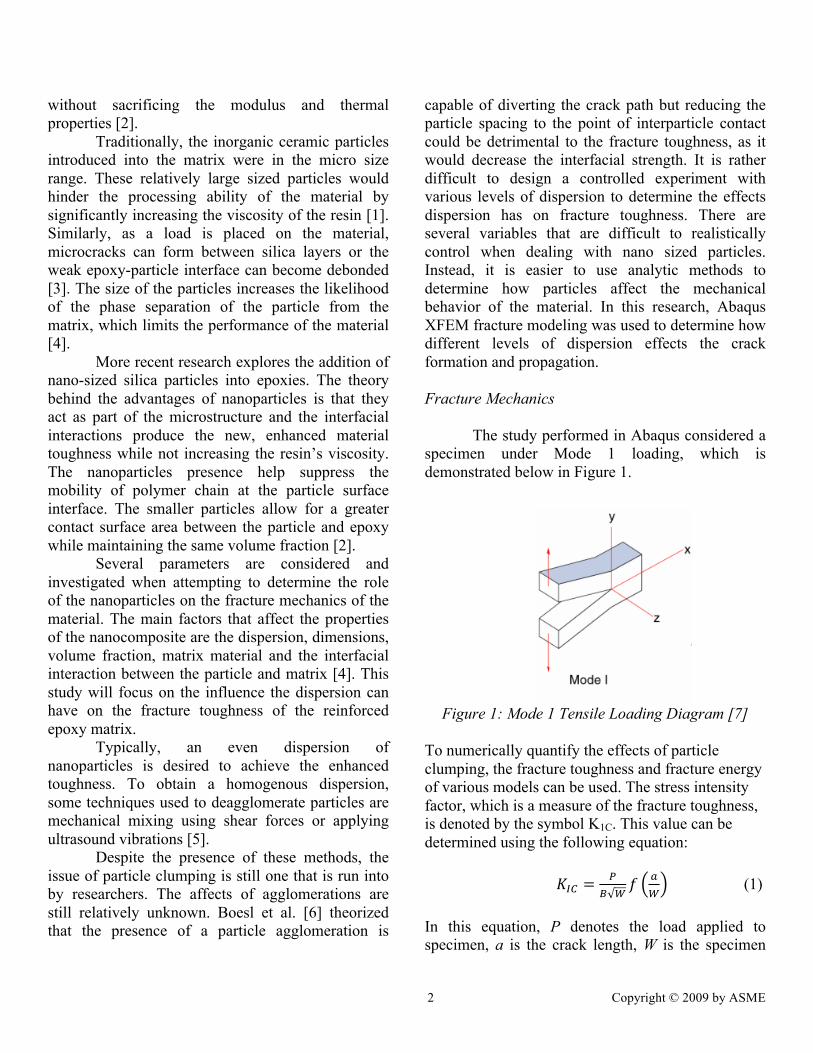
capable of diverting the crack path but reducing the particle spacing to the point of interparticle contact could be detrimental to the fracture toughness, as it would decrease the interfacial strength. It is rather difficult to design a controlled experiment with various levels of dispersion to determine the effects dispersion has on fracture toughness. There are several variables that are difficult to realistically control when dealing with nano sized particles. Instead, it is easier to use analytic methods to determine how particles affect the mechanical behavior of the material. In this research, Abaqus XFEM fracture modeling was used to determine how different levels of dispersion effects the crack formation and propagation. Fracture Mechanics The study performed in Abaqus considered a specimen under Mode 1 loading, which is demonstrated below in Figure 1.
Figure 1: Mode 1 Tensile Loading Diagram [7]
To numerically quantify the effects of particle clumping, the fracture toughness and fracture energy of various models can be used. The stress intensity factor, which is a measure of the fracture toughness, is denoted by the symbol K1C. This value can be determined using the following equation: 𝐾!" =
!! !
𝑓 !!
(1) In this equation, P denotes the load applied to specimen, a is the crack length, W is the specimen
3 Copyright © 2009 by ASME
width, and B is the specimen thickness. In this study, the specimen thickness is assumed since only a two-dimension specimen is used for the analysis in Abaqus. The dimensionless geometric factor 𝑓 !
!
can be calculated using equation (2). 𝑓 𝑎
𝑊 = 2+ 𝑎𝑊
1− 𝑎𝑊
3/2 0.886+ 4.64𝑎𝑊 − 13.32 𝑎
𝑊2+
14.72 𝑎𝑊
3− 5.60 𝑎
𝑊4 (2)
For the energy criterion, the value G indicates the amount of energy required at the crack tip for it to grow as a function of energy dissipated in the formation of new surfaces. Therefore, G can be defined as the change in potential energy divided by the change in crack area. For this study, the important criterion to consider is the critical energy release rate, G1C, which is also known as the fracture energy. This value is given by the following equation: 𝐺!! =
!!!!
!(1− 𝑣!) (3)
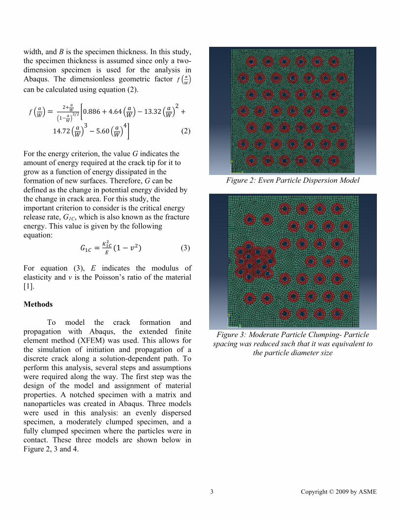
For equation (3), E indicates the modulus of elasticity and v is the Poisson’s ratio of the material [1]. Methods To model the crack formation and propagation with Abaqus, the extended finite element method (XFEM) was used. This allows for the simulation of initiation and propagation of a discrete crack along a solution-dependent path. To perform this analysis, several steps and assumptions were required along the way. The first step was the design of the model and assignment of material properties. A notched specimen with a matrix and nanoparticles was created in Abaqus. Three models were used in this analysis: an evenly dispersed specimen, a moderately clumped specimen, and a fully clumped specimen where the particles were in contact. These three models are shown below in Figure 2, 3 and 4.
Figure 2: Even Particle Dispersion Model
Figure 3: Moderate Particle Clumping- Particle
spacing was reduced such that it was equivalent to the particle diameter size

4 Copyright © 2009 by ASME
Figure 4: Severe Particle Clumping- Particle spacing was reduced to the point of interfacial
contact and the interphase region was removed for simplicity
There are four regions of interest in these models. The first is the silica particle, which possesses a high modulus of elasticity and strength. This material was given a damage initiation of 1100 MPa and a damage evolution displacement at failure of 0.01 nm. The significance of these values is demonstrated in Figure 5.
Figure 5: (Point A) Damage Initiation, (Path of A to
B) Damage Evolution [8]
The value of damage initiation, also called the yield stress, gives the stress at which the material begins to fail. The damage evolution displacement gives the
displacement the material can withstand after damage initiation until complete failure occurs.
The second is the interface region that surrounds the particle. This region was given both plastic and elastic properties. The ductile damage properties are given as a fracture strain of 0.001 and a damage evolution displacement at fracture of 0.001 nm. The elastic properties include a modulus of elasticity of 3.5 GPa, a Poisson’s Ratio of 0.35 and yield stress of 62.1 MPa. The epoxy matrix and interphase region contain the same elastic properties of a modulus of 3.5 GPa, a Poisson’s ratio of 0.35, a yield stress of 62.1 MPa, and a damage evolution displacement of 0.001 nm. The basic values of these regions are shown below in Table 1.
Table 1: Material Properties
Epoxy Silica particles
Interface region
Modulus (E)
3.50 GPa 73.0 GPa 3.50 GPa
Poisson’s Ratio (υ)
0.35 0.17 0.35
Strength 62.1 MPa 1100 MPa 62.1 MPa Next, the necessary boundary conditions were applied to specimen. On the right side of the specimen, XSYMM was used to create a symmetry constant along the x-axis direction. This fixes the right end and allows the solver to treat the specimen as one that continues in the x-axis direction. On the left side (the notched side), a displacement was placed in the positive y-direction above the notch and in the negative y-direction below the notch. A displacement of 11 nm was applied over a 2 second period. The final model with the applied boundary conditions is shown in Figure 6. The displacements placed on the notched side create a tensile, Mode 1 loading on the specimen.
5 Copyright © 2009 by ASME
Figure 6: Abaqus model with applied boundary
conditions. The orange arrows show the direction of the applied displacement and the blue arrows indicate the x-symmetry along the fixed end
To allow for a crack to form, an XFEM crack was created in Abaqus. This first required the definition of the XFEM enriched zone. For this, all regions were selected other than the interface and particle regions. This is done for a very specific reason. As the crack propagates through the matrix, splitting elements as it goes, it will eventually reach the hard particle. If the particle were within the XFEM zone, the crack would attempt to either split the particle or stop. Since the yield stress of the particle is significantly higher than the matrix, the crack is unable to split the particle and is stopped in its path. But this result is not realistic in practical application. By defining the particle and interface as not part of the XFEM zone, the crack is then forced to propagate around the particle, causing it to become debonded from the matrix. In this scenario, the crack reaches the interface region, which consists of a boundary of elements around the particle, and the elements that make up this region fail to allow the crack to continue around the particle without having to split it. This process gives a far more practical result for crack growth, since it is often the interfacial interactions between the particle and
matrix that dictate the fracture toughness of the material. Finally, the three models were meshed using quad shaped elements only and an advanced front meshing algorithm. Finally, the models were ready for the displacement loads to be placed on the material. Results To obtain a converged solution in this study, a few parameters needed to be changed in order for Abaqus to perform its analysis. First, the minimum increment step was reduced to 10-18 and the field output frequency was increased to 50 so only 50 increments were recorded to reduce the size of the files and the time it took to perform a full analysis. Upon adding these parameters, three successful tests were run, one for each model. The resulting deformed shape and crack propagation are shown below in Figures 7, 8 and 9.
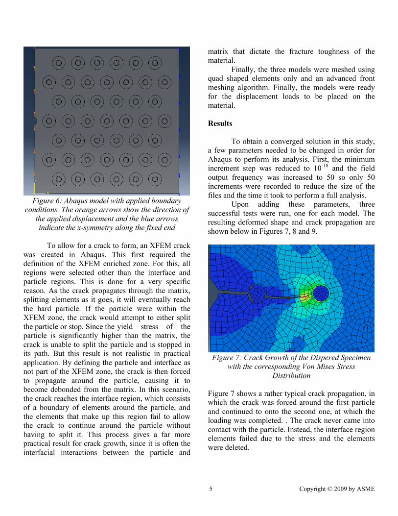
Figure 7: Crack Growth of the Dispered Specimen
with the corresponding Von Mises Stress Distribution
Figure 7 shows a rather typical crack propagation, in which the crack was forced around the first particle and continued to onto the second one, at which the loading was completed. . The crack never came into contact with the particle. Instead, the interface region elements failed due to the stress and the elements were deleted.

6 Copyright © 2009 by ASME
Figure 8: Crack Growth of the Moderately Clumped Specimen with the corresponding Von Mises Stress
Distribution
In Figure 8, the crack was forced to propagate around the particle, causing it to become partially debonded from the matrix material. The crack then continued until the loading was completed. The interface region elements were deleted as they failed.
Figure 9: Crack Growth of Severely Clumped
Specimen with the corresponding Von Mises Stress Distribution
In Figure 9, the crack attempted to split the severely clumped section of particles before coming to rest. The Von Mises stresses shown in this figure indicate the large stress field that is developing within the clumped region. This stress concentration allows for faster crack propagation, which slowed down the processor significantly, causing the time between increments to drop to the 10-13 range. This analysis
took far longer computational time due to the complexity of the model and mesh.
The correlation between force and displacement for all three models was found using the Abaqus field outputs. These graphs are shown below in Figure 10, 11 and 12.
Figure 10: Force vs. Displacement for the Dispersed
Specimen
Figure 11: Force vs. Displacement for the
Moderately Clumped Specimen

7 Copyright © 2009 by ASME
Figure 12: Force vs. Displacement for the
Moderately Clumped Specimen Conclusions
To test the effects of particle agglomerations on a reinforced epoxy, three different models were created in Abaqus, each with the same particle size, volume fraction and material properties. The levels of clumping were changed for each model to see what effects this would have on the fracture mechanics.
The results of the modeling of the crack formation and propagation for three different models shows that clumping can have an adverse affect on the fracture toughness of nanoparticle reinforced epoxies. The force was decreased as the clumping was increased at the same levels of displacement. Looking back at equation (1), this means for the same a and W value, there was a greater P which directly correlates to a greater fracture toughness. It appeared that the evenly dispersed model was able to handle the applied load best, by deflecting the crack around the particle and allowing it to continue on. The other two models had a similar result, but the close proximity of the particles caused a high stress region to develop which more rapidly deteriorated the interface between the particle and matrix.
References [1] Johnsen, B. B., Kinloch, A. J., Mohammed, R. D., Taylor, A. C., & Sprenger, S. (2007).
Toughening mechanisms of nanoparticle- modified epoxy polymers. Polymer, 48(2), 530- 541.doi:http://dx.doi.org/10.1016/j.polymer. 2006. 11.038 [2] Chen, C., Justice, R. S., Schaefer, D. W., & Baur, J. W. (2008). Highly dispersed nanosilica–epoxy resins with enhanced mechanical properties. Polymer, 49(17), 3805-3815. doi:http://dx.doi.org/10.1016/j.polymer.2008. 06.023 [3] Ma, J., Mo, M., Du, X., Rosso, P., Friedrich, K., & Kuan, H. (2008). Effect of inorganic nanoparticles on mechanical property, fracture toughness and toughening mechanism of two epoxy systems. Polymer,49(16),3510-3523. doi:http://dx.doi.org/10.1016/j.polymer.2008. 05.043 [4] Sun, L., Gibson, R. F., Gordaninejad, F., & Suhr, J. (2009). Energy absorption capability of nanocomposites: A review. Composites Science and Technology, 69(14), 2392-2409. doi:http://dx.doi.org/10.1016/j.compscitech.2009 .06.020 [5] Rosso, P., Ye, L., Friedrich, K., & Sprenger, S. (2006). A toughened epoxy resin by silica nanoparticle reinforcement. Journal of Applied Polymer Science, 100(3), 1849-1855. doi:10.1002/app.22805 [6] Benjamin P. Boesl, Gerald R. Bourne, Bhavani V. Sankar. (2011). Insitu multiscale analysis of fracture mechanisms in nanocomposites. Composites: Part B, , 1157- 1163. [7] Paulo Monteiro.Fracture mechanics. Retrieved from http://www.ce.berkeley.edu/~paulmont/ 241/fracture.pdf [8] Abaqus. (2005). Material damage and failure. Retrieved from http://imechanica.org/files/l9- damage-failure.pdf

8 Copyright © 2009 by ASME