forms on demand fod - omr · fod - omr. disclaimer the information contained in this document is...
TRANSCRIPT

Forms on Demand
For Optical Mark Readers
User Manual
July 2010
Copyright © 1997-2010 TCG Information Systems Pty. Ltd.
FoD - OMR

Disclaimer
The information contained in this document is subject to change without notice and should not be construed as a commitment by TCG Information Systems Pty. Ltd., who assumes no responsibility for any errors or omissions. TCG Information Systems Pty. Ltd., reserves the right to revise this document and to make changes to the products described herein for the purpose of product improvement at any time, without obligation by TCG Information Systems Pty. Ltd. to notify any person of such revisions or changes.
The information contained in this document is the exclusive property of TCG Information Systems Pty. Ltd. This work is protected under Australian Copyright Law and other international copyright treaties and conventions. No part of this work may be reproduced or transmitted in any form or by any means, electronic or mechanical, including photocopying and recording, or by any information storage retrieval system, except as expressly permitted in writing by TCG Information Systems Pty. Ltd., Level 3, 53 Balfour Street, Chippendale NSW 2008, Australia. Attention: Managing Director
Revision History
July 1997 - First Edition October 1997 - Revised EditionOctober 1999 - Second EditionJuly 2000 - Third EditionMay 2003 - Fourth EditionFebruary 2004 - Fifth EditionDecember 2005 - Sixth Edition, printed January 2006July 2010 - Seventh Edition, renamed FoD-OMR
Software Version
This manual supports FoD-OMR Version 7.0
Trademarks
FoD-OMR is a trademark of TCG Information Systems Pty. Ltd. Microsoft and Windows are registered trademarks of Microsoft Corporation. All other trademarks are the property of their respective owners.
Copyright
Copyright © TCG Information Systems Pty. Ltd., 1997-2010. All rights reserved.
1
OVERVIEW
This version of FoD-OMR provides for printing of both OMR-from-Image zones and Constrained Handprint fields, both of which are read from the images of pages captured by conventional page scanners. Updates include the addition of PDF417 bar code, used to supply data also able to be read from an image. All of the former facilities are retained. A summary of the features of FoD-OMR includes the facilities listed at the end of this overview.
Within the remainder of this manual, the section “Getting Started with FoD-OMR, Setting up the Response Grid” can be ignored for non-OMR forms and the chapter “Creating OMR Zones” has been amended to cover both OMR and from-Image zones.
The additional object type “Constrained Handprint” is provided to draw character cells in the “blind” color. This object type is the subject of a new chapter.
Summary of Capabilities
For OMR forms: Predefined response line format for most common OMR scanner layouts, with “build
your own” facilities for uncommon scanners or custom work.
Define the timing track, allowing individual heights of the timing marks, numbers of marks on that side and position of each of the marks on that side.
Single or double sided forms, with each side in any orientation.
Building of OMR responses in either matrix or random format.
Wide choice of OMR response shapes and attributes.
Responses optionally include framing, title blocks, shading of alternate columns, dividing lines between choice sets and text associated with choices and positioned relative to each of the responses.
Responses are able to be moved and position automatically to the underlying timing track and column layout.
Responses take all of their frames, associated texts and attributes with them as one object when moved or duplicated.
Bar codes and/or OMR pre-slugging, either fixed or taken from data.
For -from-Image forms: Tombstones on any/all corners of the page (for alignment).
Constrained Handprint fields, with control over character cell size, interval between cells, lines (or not) and shading (or not).
OMR-from-Image zones with all of the characteristics of OMR zones, but able to be placed anywhere on the page.
PDF417 bar codes to handle bulky data concisely and accurately.
For Bar Code Printing Able to print to any Windows printer, including Zebra, Paxar, Intermec, Datamax, sales
slip printers, ticket printers etc.
2
Most common formats of bar code including PDF417 and all of the UPC/EAN codes.
Calculates check digits where required.
Full UPC-128/UPC-128 bar codes, validation of the AIs with valid data checking against the AI.
Easily and fully automated using the companion FTSpooler program, without programming.
Note: All of the above barcode features are available from FTLabelPrint. See www.formtrap.com.
General Printing Letters with variable inserts into paragraphs, PostNet bar codes, signatures etc. Use for
all standard letters, student advices, report cards, etc. If this solution runs out of “puff”, migrate to the full FormTrap solution (www.formtrap.com).
Double-sided brochures and advertising materials, with custom inserts.
Mailed surveys using from-Image and Constrained Handprint capabilities.
Data Handling CSV or named CSV files (named means no requirement to define the data field names,
simply use them).
FLAT (Fixed Length ASCII Text) files.
name=data files (eg. DocType=Invoice, DocNum=I54321) produced by FormTrap. This allows sourcing data from a standard system report and forwarding that data to the labelling function.

3
CONTENTS
Summary of Capabilities 1
Getting Started with FoD-OMR
The Design Workspace 5Tool Buttons. . . . . . . . . . . . . . . . . . . . . . . . . . . . . . . . . . . . . . . . . . . . 5Status bar. . . . . . . . . . . . . . . . . . . . . . . . . . . . . . . . . . . . . . . . . . . . . . 6
Setting Up the Design Workspace 6
Setting up the Response Grid 13Changing timing mark positions. . . . . . . . . . . . . . . . . . . . . . . . . . . . 14Manually setting timing marks . . . . . . . . . . . . . . . . . . . . . . . . . . . . . 15
Beginner’s Guide 16Page Setup . . . . . . . . . . . . . . . . . . . . . . . . . . . . . . . . . . . . . . . . . . . 16Timing Lines. . . . . . . . . . . . . . . . . . . . . . . . . . . . . . . . . . . . . . . . . . . 17Student. . . . . . . . . . . . . . . . . . . . . . . . . . . . . . . . . . . . . . . . . . . . . . . 18Test . . . . . . . . . . . . . . . . . . . . . . . . . . . . . . . . . . . . . . . . . . . . . . . . . 24Question Answers . . . . . . . . . . . . . . . . . . . . . . . . . . . . . . . . . . . . . . 30Number the Question Answers (Individually) . . . . . . . . . . . . . . . . . . 35Number the Question Answers (using zones) . . . . . . . . . . . . . . . . . 41
Beginner’s Guide Data 47Date . . . . . . . . . . . . . . . . . . . . . . . . . . . . . . . . . . . . . . . . . . . . . . . . . 48Constant text objects . . . . . . . . . . . . . . . . . . . . . . . . . . . . . . . . . . . . 53Preparing Data Files . . . . . . . . . . . . . . . . . . . . . . . . . . . . . . . . . . . . 56Student. . . . . . . . . . . . . . . . . . . . . . . . . . . . . . . . . . . . . . . . . . . . . . . 62Barcode . . . . . . . . . . . . . . . . . . . . . . . . . . . . . . . . . . . . . . . . . . . . . . 65ID Mark . . . . . . . . . . . . . . . . . . . . . . . . . . . . . . . . . . . . . . . . . . . . . . 67Binary Codes Decimal 1,2,4,8.... . . . . . . . . . . . . . . . . . . . . . . . . . . . 68 Binary Codes Decimal Same Plane Zone (1, 2, 4, 8) . . . . . . . . . . . 70 Binary Coded Decimal Random Zone (1, 2, 4, 7) . . . . . . . . . . . . . . 73Printing the form with merged data . . . . . . . . . . . . . . . . . . . . . . . . . 74
Creating OMR Zones
About OMR zones 76Zone elements and choices . . . . . . . . . . . . . . . . . . . . . . . . . . . . . . . 77‘OMR blind’ colors . . . . . . . . . . . . . . . . . . . . . . . . . . . . . . . . . . . . . . 77
Creating matrix zones 77Matrix zones with one or two elements . . . . . . . . . . . . . . . . . . . . . . 78Matrix Zone with choices and elements in the same plane . . . . . . . 79Matrix zone properties . . . . . . . . . . . . . . . . . . . . . . . . . . . . . . . . . . . 79
Creating random zones 81
Assigning text to choices 81Positioning text and response shapes . . . . . . . . . . . . . . . . . . . . . . . 83Decorating zones . . . . . . . . . . . . . . . . . . . . . . . . . . . . . . . . . . . . . . . 83Format . . . . . . . . . . . . . . . . . . . . . . . . . . . . . . . . . . . . . . . . . . . . . . . 85Font . . . . . . . . . . . . . . . . . . . . . . . . . . . . . . . . . . . . . . . . . . . . . . . . . 86
Resizing zones and moving choices 86

4
Matrix zones. . . . . . . . . . . . . . . . . . . . . . . . . . . . . . . . . . . . . . . . . . . 86Random zones. . . . . . . . . . . . . . . . . . . . . . . . . . . . . . . . . . . . . . . . . 87Duplicating zones with the “CTRL” method . . . . . . . . . . . . . . . . . . . 88Combining Zones. . . . . . . . . . . . . . . . . . . . . . . . . . . . . . . . . . . . . . . 88
Creating constrained handprint fields
About constrained handprint fields 89
Constrained handprint properties 89
Working with Graphics
Preparing your workspace 91
Setting preferences . . . . . . . . . . . . . . . . . . . . . . . . . . . . . . . . . . . . . 91Nudge distance . . . . . . . . . . . . . . . . . . . . . . . . . . . . . . . . . . . . . . . . 92Difference between two objects . . . . . . . . . . . . . . . . . . . . . . . . . . . . 93Adjusting the zoom . . . . . . . . . . . . . . . . . . . . . . . . . . . . . . . . . . . . . 93
Drawing graphics objects 93
Adding text . . . . . . . . . . . . . . . . . . . . . . . . . . . . . . . . . . . . . . . . . . . . 96Adding barcodes . . . . . . . . . . . . . . . . . . . . . . . . . . . . . . . . . . . . . . . 98PDF417 barcode - special conditions . . . . . . . . . . . . . . . . . . . . . . 100Inserting pictures . . . . . . . . . . . . . . . . . . . . . . . . . . . . . . . . . . . . . . 100
Arranging objects on your form 102
Cut and Paste . . . . . . . . . . . . . . . . . . . . . . . . . . . . . . . . . . . . . . . . 102Moving and resizing objects. . . . . . . . . . . . . . . . . . . . . . . . . . . . . . 102Aligning objects . . . . . . . . . . . . . . . . . . . . . . . . . . . . . . . . . . . . . . . 104
Changing object stacking 106
Merging Data from Files
Preparing your data files 108
Defining fields 109Defining fields for delimited data formats . . . . . . . . . . . . . . . . . . . . 110Defining fields for fixed data formats . . . . . . . . . . . . . . . . . . . . . . . 111
Linking to fields 112
Masking 113Masking dates . . . . . . . . . . . . . . . . . . . . . . . . . . . . . . . . . . . . . . . . 114Masking currency. . . . . . . . . . . . . . . . . . . . . . . . . . . . . . . . . . . . . . 114
Printing forms with merged data 117
Appendix A Known Issues
Smooth Edges 119
Appendix B Batch Printing
Command line arguments 121
Index

5
GETTING STARTED WITH FOD-OMR
1 The Design Workspace
The FoD-OMR design workspace is where forms take shape, and FoD-OMR can have many forms open at once. This chapter provides information about setting up FoD-OMR to work with your Optical Mark Reader or Image Scanner, and using the design workspace to create OMR forms.
Figure 1.1 The FoD-OMR design workspace with an empty form
Tool Buttons
The FoD-OMR window has four main toolbars for quickly accessing commands: the Forms toolbar has functions for saving, loading and printing forms and the edit tools; the Draw toolbar has functions for placing response zones, text and pictures; the Formatting toolbar has functions for changing the style of text; and the Tools toolbar has special functions for aligning, nudging and viewing objects.
Two additional toolbars, the Zoom toolbar and Alignment toolbar, can be accessed from the Tools toolbar. By default these toolbars “float” but can also be dragged and anchored in the toolbar area if more convenient.
As each function or command is discussed in this guide, its tool button is shown on the left of the page.

6
Status bar
Beneath the design workspace is the status bar showing the locations of the mouse and any selected objects, and selected object dimensions (see Figure 1.2) Channel and Row are shown only for OMR forms.
Figure 1.2 The Status Bar
Setting Up the Design Workspace
Paper Orientation and Double sided printing are invoked from Page Setup ... (from the File menu item):
Figure 1.3 Page Setup Options
Paper Size
Select a paper size for your printer. To change a form’s page size, select one of the standard page sizes available in the list. Custom page sizes can be selected for special printers or paper sizes.
Orientation
Orentation should be chosen to reduce skew on laser printed forms, and alternately, to reduce sheet damage where the sheet enters the scanner on commercially printed forms.
Mouse offset from the
Nearest channel and Offset of selected object fromthe top left of the form
top left of the form
row from the mouse

7
Laser printed forms should generally have timing marks bottom or right for normal use, allowing response position to be closer to the timing marks, thus reducing skew.
Figure 1.4 Reccomendation - Laser Printed Forms
Booklet forms should be printed to avoid damage on the timing mark entering the scanner first, see figure 1.5 for a sheet fed from right to left through a scanner.
Figure 1.5 Reccommendation - Booklet Forms
Your scanner may include restrictions on Form ID marks (generally best on the first line into the scanner) and for paper folds across the short dimension (generally use a large timing mark and IGNORE marks in this area).

8
Double sided printing (duplex)
Select the type of double sided printing (duplexing) to be used for the form. Choose from simplex (one sided printing), flip on long edge or flip on short edge.
When Duplex printing is selected the Front and Back buttons on the toolbar become available. Click the Front button to design the front of the form and click the Back button to design the back of the form.
Tombstones
at the bottom left should be pressed if you require a form where the data is scanned from an image rather than being defined by OMR marks. If you require a Tombstone form, select the box, otherwise go to Grid below to set up an OMR form.
When you press this screen appears. Enter the required tombstones by ticking their positions (which are relative to the Orientation) and complete the Height and Width.
Figure 1.6 Tombstones
Ignore the remainder of this chapter for from-Image forms.
Number 1 indicates the front of the form
Number 2 indicates the back of the form
The arrows indicate how the form is fed through the scanner for a Right to Left scanner.
9
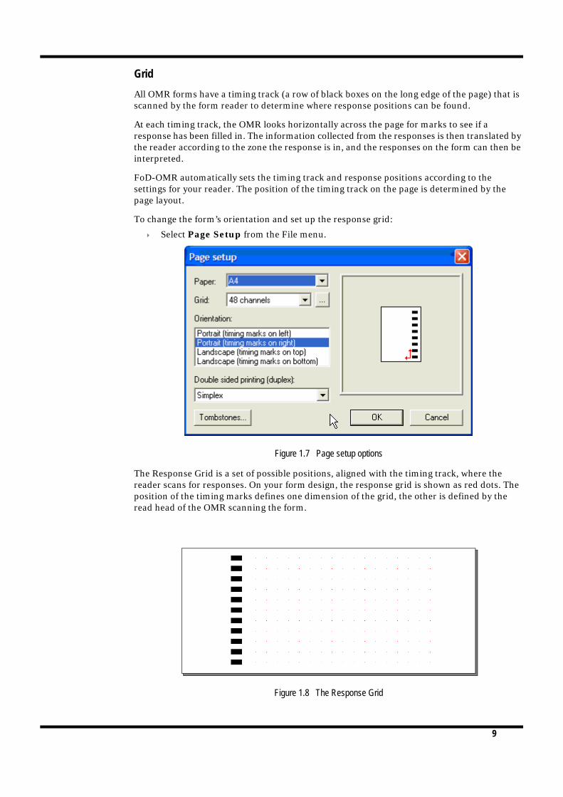
Grid
All OMR forms have a timing track (a row of black boxes on the long edge of the page) that is scanned by the form reader to determine where response positions can be found.
At each timing track, the OMR looks horizontally across the page for marks to see if a response has been filled in. The information collected from the responses is then translated by the reader according to the zone the response is in, and the responses on the form can then be interpreted.
FoD-OMR automatically sets the timing track and response positions according to the settings for your reader. The position of the timing track on the page is determined by the page layout.
To change the form’s orientation and set up the response grid:
Select Page Setup from the File menu.
Figure 1.7 Page setup options
The Response Grid is a set of possible positions, aligned with the timing track, where the reader scans for responses. On your form design, the response grid is shown as red dots. The position of the timing marks defines one dimension of the grid, the other is defined by the read head of the OMR scanning the form.
Figure 1.8 The Response Grid

10
To change the response grid, select a compatible grid for your OMR reader, or you can create a custom definition.
Creating a custom grid definition
Click the Finder button next to the Grid list to create a custom grid definition.
Figure 1.9 A custom grid definition - 1200 DPI measurements
To change the position of the timing track, set the following dimensions:
The distance from the edge of the page to the outer edge of the timing mark (value A on the dialog box diagram).
The width of the timing mark (value B).
The offset of the center of the possible response positions from the center of the timing marks (value E).
The following settings define a channel bank:
The number of columns in the channel. This is the maximum number of response positions along each timing line.
The distance from the paper edge to the middle of the first column (value C in the dialog box diagram in Figure 1.9).
The distance between response positions in the column (value D).
If your OMR supports two channel banks, you can create banks by clicking Two sets of channels and setting up the second bank.
Note: Ensure you select the horizontal timing mark spacing compatible with your OMR scanner.

11
Figure 1.10 Two channel banks
To change the shape and size of the timing marks, click the Marks button and set the following thresholds:
Minimum size of the mark and Maximum size of the mark set height threshold for all timing marks
The Minimum space between marks sets the smallest distance required between marks.
Figure 1.11 Timing mark settings
Bank 1 Bank 2
When you define
‘Minimum space’, you are setting
the minimum distance between marks.
When you define
‘size’, you are
setting the height
threshold.

12
Scanners using any channel as the timing line
Some scanners (such as DRS) have the capacity to use any channel as the "Clock Mark" (Timing Line) channel. In Figure 1.12 are the form and the Grid window for a form of this type. A central timing line removes skew, particularly on lasers such as Xerox large scale equipment where sheet travel is long edge leading.
Figure 1.12 Clock Mark (Timing Line) Centered Form
We have used 102 timing lines per A4 sheet, double sided, collecting 400 individual observations per sheet successfully in huge applications using a short distance from central timing line and an over-large response position for Australian Elections.
Standard 40-channel read head forms are successfully printed on lasers with standard 1/4" unprintable margins by using the first of the normal data columns for the timing mark.
Changing the deafult mark Width and Distance from Paper Edge
As shown above, Distance from edge of paper (A) and Width (B) are readily adjusted. If the particular laser printer you wish to use is slightly "off", ensure the middle of the response marks is precise by adjusting Start at (C).
Saving the custom definition
Once you have created custom timing line and channel definitions compatible with your OMR, click Save As and type a grid name to store the grid definitions in the list available from the Page setup dialog box.
Now that the design workspace is set up for your OMR, the first step in creating an OMR form is to create the timing line and set up the response grid ready for OMR zones.
Deleting a customer definition
Click Delete to remove a redundant custom definition.

13
Setting up the Response Grid
To place the timing lines on your form, click Timing Lines tool button to open the Timing Marks dialog box.
Figure 1.13 The Timing Marks dialog box
The default timing mark values are taken from your grid definition (see “Creating a custom grid definition” on page 1-10), but you can enter custom values for:
The Number of timing marks that appear on the edge of your form.
The distance between the paper edge and the centre of the first timing mark (value A on the following diagram).
The height of each mark (value B).
The space between mark centres (value C).
Figure 1.14 Timing marks settings
When you click OK, each timing mark appears in red with editing handles at its corners, and the entire line has black handles. This means you can change the position of the timing marks, and move them around your page so you can accurately place response grids.
The black handles that appear around the all the timing marks allow you to set the height of the timing track on the page, and the handles around each timing mark set the position of each mark on the timing track.
Space (C)
Paper edge
Distance (A)
Size (B)
Number of timing marks

14
To change the size of the timing track and the placement of the channels, select a mark to shift, and drag it with the mouse to its new location.
Figure 1.15 Editing the timing track
Changing timing mark positions
To spread or shrink the entire set of timing marks, drag the black handles to proportionally change the spacing and size between timing marks.
You can also move a group of timing marks by selecting multiple marks (either by clicking them with the Shift key down, or clicking and dragging the mouse around a group) and dragging them to a new location on the timing track.
Timing mark dimensions
You can quickly set the dimensions of timing marks, or set the spacing between timing marks from the shortcut menu by right-clicking a timing mark:
Select Dimensions to open the timing mark dialog box and enter an offset from the paper edge and a height for the mark, the size of the timing mark and the spacing between marks (see Figure 1.14).
Select the Sizes menu to set the size of each mark to either the largest or smallest size.
Select the Spaces menu to set the distance between each mark, or select Space evenly to distribute the marks evenly along the timing track.
Once you have set up your timing marks, select Apply changes from the shortcut menu to return to your form.
The black handles size the entire timing track.
These handles place each timing mark.
Select a groupof timing marks...
and drag themto their new location.
15
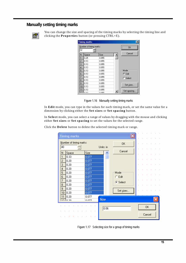
Manually setting timing marks
You can change the size and spacing of the timing marks by selecting the timing line and clicking the Properties button (or pressing CTRL+E).
Figure 1.16 Manually setting timing marks
In Edit mode, you can type in the values for each timing mark, or set the same value for a dimension by clicking either the Set sizes or Set spacing button.
In Select mode, you can select a range of values by dragging with the mouse and clicking either Set sizes or Set spacing to set the values for the selected range.
Click the Delete button to delete the selected timing mark or range.
Figure 1.17 Selecting size for a group of timing marks

16
Beginner’s Guide
This guide is an introduction to setting up a FoD-OMR form, with different OMR zones (Matrix and Random, single choice and summation), other objects together with how to arrange these objects on the form.
Page Setup
First step is to set up the page in File > Page Setup. Set Paper to A4 or Letter and Grid to 48 channels. If you have a 40 channel scanner be prepared to adjust position of channels down to fit.
Save the form name it "Beginner's Guide" or another appropriate name.

17
In Tools > Preferences set the Measurement units to 300 dpi (1/300 of inch). This allows for both 48 and 40 channel scanners without decimals (channel spacing is 50/300 for 48 channel, or 60/300 for 40 channel, other items items adjust to fractions of 48 and 40 channel measurements.
Timing Lines
To define the timing lines select Timing Lines in the Draw toolbar. In the dialog box, set Number of timing marks to 41.

18
The Timing Marks appear on the right side of the form in red. Right-click anywhere on the form and click Apply changes.
You can now modify the spacing of the timing marks by right-clicking the timing marks and select Properties. In the dialog box you can change the space between the timing marks as well as their size.
Change the spacing to create one group of 10, five groups of 5, one of 4 and the last 2 together. Set the spacing evenly between the groups.
Student
Matrix Zones for responses are define by a series of mouse clicks. You define start point (1), then spacing between choices (2), number of choices (3), spacing and orientation between elements (4), and finally number of elements (5).
To set up a student numberof six digits:
1. Click the Matrix Zone button. The mouse pointer changes to a cross-hair. 2. Select where to "click" to start the zone. You can see Row and Column in the Sta-

19
tus Bar (bottom of the window).
3. Click the second choice of the first element to define the element's orientation (along columns or rows) and the spacing between choices.
4. Click the last choice of the first element to define the number of choices.5. Click the first choice of the second element to define the spacing between ele-
ments.6. Click the first choice of the last element to complete the zone.
Open the properties of the zone, either by double clicking the zone, or by right clicking and selecting Properties.
From the Response shape area, select the shape to the right of NULL and set White filled.

20
There are standard text choices to choose from, . Choose Numbers (from 0).
In the Matrix tab, check the Horizontal origin is 40 and Vertical origin is 1, change them if different.
Jump to the Plate tab to change the color of the response text. FoD OMR regonizes only "three colors": Black, Blind (shown as Red) and Other (shown as Blue). More information on blind and other colors is available in the manual PAGE REF.

21
Set Plate to Blind.
On the Frame tab mark all three choices. This tab frames the zone with borders, internal lines and shading.

22
On the Border tab, untick Auto offsets and change the settings to those shown below. Width should be increased to the second thinnest option.
In the Title Line dialog box you create the line dividing the Title space from the choices. Set the Placement to Top, untick Auto distance and set to 25. Width should be increased to the second thinnest option.
23
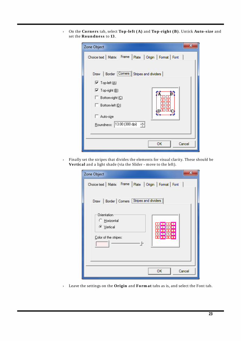
On the Corners tab, select Top-left (A) and Top-right (B). Untick Auto-size and set the Roundness to 13.
Finally set the stripes that divides the elements for visual clarity. These should be Vertical and a light shade (via the Slider - move to the left).
Leave the settings on the Origin and Format tabs as is, and select the Font tab.

24
Select Arial font and change the Size to 6. Click OK. The zone should now look as below.
Test
There are a number of ways to copy a Matrix zone:
Copy, Paste and change the values in the Matrix tab
Copy, Paste, Drag and Resize
Use Ctrl+Drag to make the copy, then Resize
Copy and use Paste At to make the copy, then Resize
Make, then delete each new Test field until you have used all methods please.
Copy and Paste and change the values in the Matrix tab:
Copy and Paste the Student zone. The zone is placed on top of the already existing zone.

25
Open the Properties of the zone and in the Matrix tab change the Horizontal origin to 34, and set Repeats, Count to 4.
Leave the other settings as is.
Click OK. Your two zones should now look as below.

26
Copy, Paste, Drag and Resize:
Copy and Paste the Student field. The field is placed on top of the already existing field.
Drag the zone to the left until only one repeat overlaps and let go of the mouse.

27
Select the middle black handle on the right side and resize the zone to 4 repeats.
28
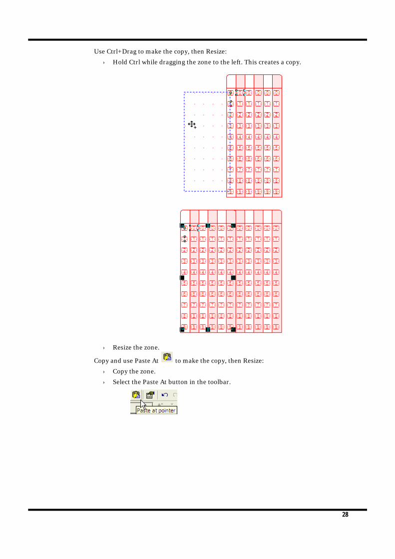
Use Ctrl+Drag to make the copy, then Resize:
Hold Ctrl while dragging the zone to the left. This creates a copy.
Resize the zone.
Copy and use Paste At to make the copy, then Resize:
Copy the zone.
Select the Paste At button in the toolbar.

29
The mouse pointer changes to a hand.
You can check the Row and Column in the Status bar to ensure the position is correct.
30
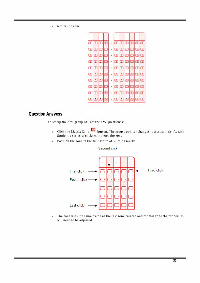
Resize the zone.
Question Answers
To set up the first group of 5 (of the 125 Questions):
Click the Matrix Zone button. The mouse pointer changes to a cross-hair. As with Student a series of clicks completes the zone.
Position the zone in the first group of 5 timing marks.
The zone uses the same frame as the last zone created and for this zone the properties will need to be adjusted.

31
Open Properties of the zone (opens to the Choice Text tab) and use
to set Letters (upper case).
On the Matrix tab check the settings match those below. The different order of mouse clicks used to create the zone inverts the Horizontal and Vertical settings for Choices and Repeats.

32
The settings on the Frame tab need to be changed to move the title line to the left rather than top. Extend the Left (B) border and shorten Top (A).
In the Title Line dialog box, click Left and leave the other settings as is.

33
On Corners tick to set rounding on all corners.
On Stripes, change to Horizontal.

34
Your zone should now look like below.
Copy the zone to create the 25 groups:
While holding Ctrl, drag the zone to the right until it is in Channel 14. Continue to copy the zone until 5 are spaced evenly across the row. Any method for moving zones (listed in Test section) is suitable.
You can continue to copy the zones individually, moving them to the next row of zones.
Alternatively, select all five zones and copy and paste them as a group. Selecting the zones can be done by dragging the mouse over them (while holding left mouse button) or selecting each in turn while holding Shift.

35
There should now be 5 x 5 question zones on the form.
Number the Question Answers (Individually)
There are several ways of adding the text Q1-Q125 to the form. Two ways are explored in this guide. The first one we will explore involves creating Text objects.
Create a Text Object:

36
To place the first Text object, select the Text tool. The mouse pointer changes to a cross hair.
Drag the mouse to create the Text Object. The Text Object dialog box opens.
Type "Q1-Q5" in the Definition tab.
On the Format tab set the Horizontal Alignment to Right.

37
On the Plate tab, set Plate to Black.

38
On the Font tab set the Font size to 9. Click OK.
The Text object is not aligned correctly. This is because Line Spacing is set to Single (default setting), but it can be changed on the Format tab. The text should be spaced to the same as the space between the Timing Marks.

39
Check the space set between the Timing Marks by accessing Properties by right-clicking the Timing Marks.
Open the Format tab in the Text Object Properties. Set the Line spacing Type to Exact. Set Exact spacing to 60.00.
40
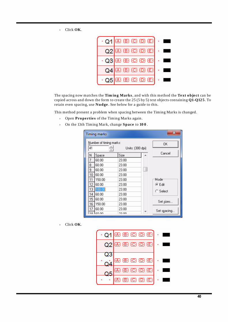
Click OK.
The spacing now matches the Timing Marks, and with this method the Text object can be copied across and down the form to create the 25 (5 by 5) text objects containing Q1-Q125. To retain even spacing, use Nudge. See below for a guide to this.
This method present a problem when spacing between the Timing Marks is changed.
Open Properties of the Timing Marks again.
On the 13th Timing Mark, change Space to 100.
Click OK.
41
The spacing of Timing Marks has changed, but the Text has not.
Change the Timing Marks spacing back as before.
Using Nudge to arrange Text Objects
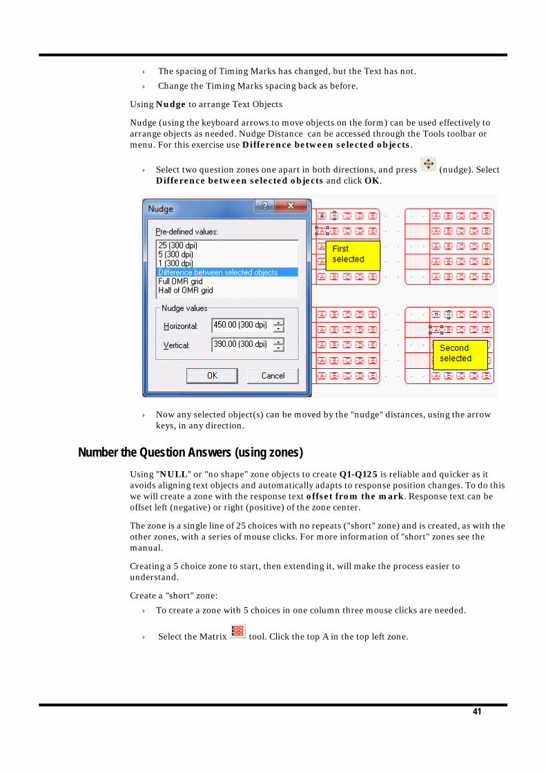
Nudge (using the keyboard arrows to move objects on the form) can be used effectively to arrange objects as needed. Nudge Distance can be accessed through the Tools toolbar or menu. For this exercise use Difference between selected objects.
Select two question zones one apart in both directions, and press (nudge). Select Difference between selected objects and click OK.
Now any selected object(s) can be moved by the "nudge" distances, using the arrow keys, in any direction.
Number the Question Answers (using zones)
Using "NULL" or "no shape" zone objects to create Q1-Q125 is reliable and quicker as it avoids aligning text objects and automatically adapts to response position changes. To do this we will create a zone with the response text offset from the mark. Response text can be offset left (negative) or right (positive) of the zone center.
The zone is a single line of 25 choices with no repeats ("short" zone) and is created, as with the other zones, with a series of mouse clicks. For more information of "short" zones see the manual.
Creating a 5 choice zone to start, then extending it, will make the process easier to understand.
Create a "short" zone:
To create a zone with 5 choices in one column three mouse clicks are needed.
Select the Matrix tool. Click the top A in the top left zone.

42
Click the second A, and finally the fifth A as below.
To "finish" the zone with 5 Choices and no Repeats, right-click the mouse anywhere on the page.
Open the Properties of the Zone.
Set the Response shape to NULL, and type Q1-Q5 in the Choice text box.
Click OK.
The new zone is placed on top the other and has the same Properties as the previously created zone, so there are a few changes to make.
Open Properties again.
Choice text needs to move left, a negative Horizontal offset. Set to -30.00.

43
Untick White filled.
Leave Matrix as is.
On the Frame tab, untick Border, Dividing lines, Stripes. Settings for the underlying zone remain as is.

44
On the Plate tab, set the plate to Black.
On the Format tab, set the Horizontal Alignment to Right.

45
On the Font tab, change the Size to 9.
Click OK. Your two zones should now look like below.
Rather than repeating this for each of the 25 zones that make up the 125 Questions, extending it over 25 rows saves time and effort.

46
On the Matrix tab, set the number of Choices to 25.
On the Choice text tab, there are now 25 choices. Extend the numbers as shown on the sample PDF.
Click OK.
Copy and Paste the zone to the other columns, using one of the methods tried above in the Test section.
Renumber the zones as per the sample PDF.

47
Your form should now look as below.
Beginner’s Guide Data
You can insert data from files into zone, text and barcode objects on your form, and dynamically merge the data when the form is printed. For this form we'll use a data file to pre-fill the Student Name, Student Number and Test Number.
Save this LINK to the folder where the form is saved.

48
Date
The Date field is made up of 4 OMR zones. Mth is a Random Zone, the other three Matrix. As the Random zone can't be assigned a frame, we will use a combination of frames and graphic objects to create this group.
Create a "short" zone of 9 choices starting in Channel 16, Row 1.
Open Properties and name the choices 10 to 18.
Check that the settings are as below.
On the Frame tab untick all three choices.

49
Click OK.
Select the Random zone tool from the toolbar. This zone contains 12 choices in two rows, each created with individual clicks. Create two rows of 6, in the order below.
Name the choices in short month format (Jan, Feb ... Nov, Dec).

50
Set the Response shape to the second right from NULL.
On the Format tab, set Horizontal alignment to Center.
Click OK.
Create a "short" zone with 9 choices in Channel 19.
Open Properties and select Numbers (from 1) in .
Change the Response shape back to the shape to the right of NULL.

51
On the Frame tab, select Border, but untick Dividing lines and Stripes if selected. The Border of this zone will be used to cover the other three zones so the Offsets need to be changed. Change the settings as below.
In Title line set to Top.
Click OK.
Create a "short" zone of 3 in the empty Channel.
Open Properties and name the choices 10, 20, 30.

52
Click OK.
Since the zone containing the Frame for the group is a single column, it's not possible to use the Dividing lines in the Frame tab. Two Lines (Graphic Objects) can be used to create the Dividing lines instead.
Select the Vertical line tool in the toolbar. The mouse pointer changes to a cross hair. Draw a line between "Month" and "Day".
Extend the line to the bottom and top border. You can change the Nudge distance to 1 (300 dpi) for fine tuning the placement.
Open Properties and change Plate to Blind.

53
Copy and Paste the line, or draw another line, and place it between "Month" and "Year".
Add three text objects ("Day", "Mth", "Yr") in the title space above the group. If they appear in Red, change Plate to Black in Properties.
Constant text objects
Add the constant text objects above the Date, Test and Student zones. The Alignment tools are useful in placing these objects. More information on Alignment Tools can be found in the manual.
Aligning objects:
Select . While holding the left mouse button drag across the screen to place your text object. This opens the Text object dialog box (Properties). In Definition type "Student".
On the Format tab set the Horizontal Alignment to Center.
Set Plate to Black.
On the Font tab, set Font size to 12. Click OK.
Toogle the Alignment toolbar, if not already open, by clicking . This opens the
Alignment toolbar . This can be docked in the toolbar menu, or left floating.
Select the "Student" text object and click , the mouse pointer changes to a hand. This alignment tool uses two clicks to center an object between the two selected points.

54
Click the horizontal edges of the Student zone.
The text is now centered over the zone.
Do the same for Test and Date zone.
Add the text field "Student: / Student no.: / Test:"

55
Use the text tool to create the object. In Definition type the three line.
Set Horizontal alignment to right in Format tab. Set the Line spacing to Exact: 60 (300 dpi).
Set Plate to Black.
Set Font size to 12.
Click OK.
With the Text object selected click , the mouse pointer changes to a hand. Select the left edge of the first Q1-Q125 zone. The object aligns with the other zones in the left column..
Click and align the object to the Student zone.
To create the sample text (to be substituted from the data file):
Copy and paste the text object. The copied object is placed on top of the first object.
Open Properties and change the Horizontal alignment (on the Format tab) to Left. This moves the text object. If it is too close to the constant text object, use Nudge to move slightly to the right.

56
Open Properties again. Change the text to a sample of the text that will appear on the form.
Preparing Data Files
FoD-OMR can use data files in three distinct 'formats':
Fixed data files have the same data field always at the same location on each line in the data file.
Delimited data files have their fields separated by a character known as a delimiter.
Delimited named data files are like the Delimited data files in that the fields are separated by a delimiter. They also have a header line which allows more flexibility in forms design.
This Beginner's Guide uses a Fixed data file. More information on Merging Data Files can be found in the manual.
Open the text file provided. The fields in the file all have the same starting point, but not always the same length. Student and Test (and Date, not used in this form) are always the same length, but Name varies in length.
You can set up the fields prior to linking, or as needed by creating fields through linking objects (text, zone, barcode objects).
To set up the fields before linking:
You need the first 4 records of this file, Name, Surname, StudentNo and Test.
Count the characters (and space) for each field to determine the length of each.

57
In the Tools menu, select External data....
This opens Field definitions dialog box. Click New.

58
FoD-OMR asks you what type of input data used. Select Data fields are of fixed size.
The Field dialog box opens. Type in your first field, "FirstName", and set the length of the first record in the text file. Click OK.
Click New again and add "Surname". The Start point changes automatically to accommodate the fields created prior.

59
Add "StudentNo" and "Test".
Your fields are now available to link. The symbol to the left of the name is a green "broken link". This signifies that the field hasn't yet been linked.
Below are the instructions on creating fields as you need them and it's also the method of linking previously created fields to text. Delete the fields created, as we'll recreate them later.
Open the sample text Properties. Mark the "FirstName" only, and click Link selection...

60
This opens the Link to field dialog box. If you have created the fields previously they will appear in the drop down menu.
Since the fields were deleted, the list only contains the predefined fields (such as Page, Date etc).
To add a field, click next to Field, this opens the Field dialog box. Type FirstName and change the Max Length to 16.

61
Click OK. Click OK in the Link to field dialog box.
The linked text is highlighted and the field is available in the Linked records list, where you can edit the link (or delete it).
Link the remaining fields.
Click OK.

62
Open External data... from the Tools menu. The "broken link" has now changed to an "unbroken link" symbol.
If you have added the Fields in a different order to how they appear in the data file, you can change the Order and Max Length in Field Definitions.
Student
You can now use the Fields created to pre-fill some of the OMR zones.
Open Properties of the Student zone.
Linking a zone to a field is done in the Origin tab of the Zone Properties. Default setting is Constant. To create a new field, click the button and proceed as before when

63
creating a field. As we have already created StudentNo, select it from the drop down menu.
On Encoding method select 0-9.
In Encoding value, you can enter a sample value, to see on the form (prior to printing) how the printed form will appear. Enter 6 numbers to "pre-slugg" the zone.
Select the Standard size of Encoding marks.

64
Click OK.
If the Student number should appear in the Title line of the zone, copy the "Student" text object and place it in the title line. Change the definition to a sample Student Number.

65
Link the text to StudentNo.
It's not possible to change the spacing of the text substituted from a data file, so the Student Number is centered in the Title line.
Link the Test zone to the Test record.
Barcode
To add a barcode:

66
Click , and drag the mouse pointer where you want to place the barcode. The Barcode dialog box opens.
Set Symbology to Code 2 of 5 int.
Click Link all... and link to Test.
Click OK.
Adjust the size of the barcode if needed by dragging the black handles that appear around the barcode when selected.
67
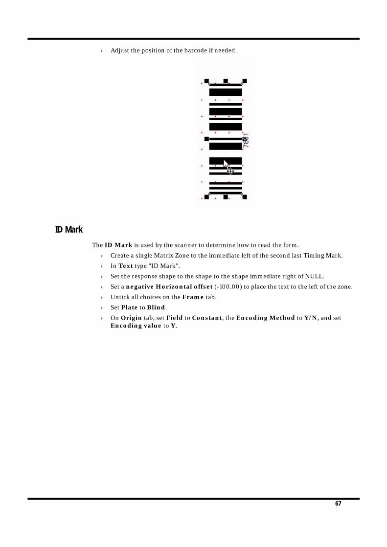
Adjust the position of the barcode if needed.
ID Mark
The ID Mark is used by the scanner to determine how to read the form.
Create a single Matrix Zone to the immediate left of the second last Timing Mark.
In Text type "ID Mark".
Set the response shape to the shape to the shape immediate right of NULL.
Set a negative Horizontal offset (-100.00) to place the text to the left of the zone.
Untick all choices on the Frame tab.
Set Plate to Blind.
On Origin tab, set Field to Constant, the Encoding Method to Y/N, and set Encoding value to Y.

68
Choose Custom in Pre-defined sizes. Set Width to 45, and Height to 23 (the same as the Timing Marks).
Set Font size to 9.
Click OK.
Binary Codes Decimal 1,2,4,8...
Binary numbers are used to show data on OMR forms.
To create the 20 Choice "short" zone directly underneath the Question zones, you need three mouse clicks.
Select from the toolbar.
Check the Status Bar to make the first mouse click in Channel 45, Row 36.
Place the second click to the right (Channel 46), and the final, making the count 20, in Channel 26, Row 36.
Open Properties and tick White filled if not already selected.
Set Offset from mark (both Horizontal and Vertical) to 0.00.

69
Check that the Response shape is set to the shape to the right of NULL.
Click OK.
Open Properties, and select the Origin tab.
Select StudentNo from the drop down menu.

70
Select BCD 1,2,4,8... in Encoding method, and type in the sample value in Encoding value.
Click OK.
Add the Constant text "Binary: Student987654 (6 digit maximum)". Use the alignment tools to place the text.
Binary Codes Decimal Same Plane Zone (1, 2, 4, 8)
This is another zone that can be used to show data, or can be marked for single digits in less space.
When both Choices and Repeats are in the same plane (Channel or Row), zones are called "Same Plane Zones". More information can be found in the manual. This is set up in Properties of the zone.
Set up a "Short" zone up of 4 choices. For this you need three mouse clicks.
Right click to finish the zone.
Open Properties.
Set the Response shape to the fourth from NULL .

71
In select Binary encoding, 1-2-4-8.
On the Matrix tab, check the Horizontal origin is set to 3, and Vertical origin is set to 37.
Leave Choices: Count and Spacing as is, and set Repeats: Count to 6, and Spacing to 5. Make sure Repeats are Horizontal.
On the Frame tab, leave all three choices unselected.
Make sure Plate is set to Blind.

72
On the Format zone, set Horizontal alignment to Center and the Line spacing to single.
On the Font tab, change the Size to 6.
Click OK.
Open Properties, and select the Origin tab.
Select StudentNo from the drop down menu.

73
Select BCD 1,2,4,8 in Encoding method, and type in the sample value in Encoding value.
Click OK.
Add the Constant text "BCD 1 2 4 8: Student987654".
Binary Coded Decimal Random Zone (1, 2, 4, 7)
The last two rows of zones are best done by using a Random zone. For more information on Random Zones see the manual.
Select the Random zone icon .
With four mouse clicks create a zone of four.
Right click to complete the zone.
As this is a Random zone you have to right click and select Properties to open the Properties dialog box. Open Properties.
Select Binary encoding, 1-2-4-7 in .
Check the Plate is set to Blind.

74
Click OK.
There is no tab available in Properties to adjust the placement of the zone, so do this manually.
Copy and Paste the zone until there are 6 groups of 4.
As this is a random zone, you cannot prefill this from a data file.
Add the Constant text "BCD 1 2 4 7: Student987654 (as single digit random zone)".
Printing the form with merged data
Now that all elements on the form have been defined, it's time to print it with the data file. The linked objects will be replaced by the values in the data file. The data file used is defined in File menu, Print..., (shortcut ctrl + p).
Select the Merge tab.

75
To define the data file used, click and find the .txt file saved earlier.
Confirm which printer to use, then click Print.

76
CREATING OMR ZONES
7 OMR zones are drawn in two ways. On an OMR form, the zones are linked to the form’s Response Grid as described in the previous chapter; alternatively the OMR zone can be drawn as an OMR-from-Image zone free form anywhere on the page. As both versions of OMR zones differ only in one aspect, this chapter describes both.
About OMR zones
Zones are a way of grouping response shapes together to present a unified set of choices to the person filling out your form. There are two fundamental types of zone:
Matrix zones are a symmetrical arrangement of a related set of choices. This is the most common type of zone.
Random zones are comprised of a random arrangement of choices, and each random zone can have a unique layout.
Figure 7.1 illustrates the difference between matrix and random zones.
Figure 7.1 Matrix and Random zones
A
B
C
D
Matrix zone
Random zone
A
B
C
D
A
B
C
D
A
B
C
D
A
D
B
C
E
77
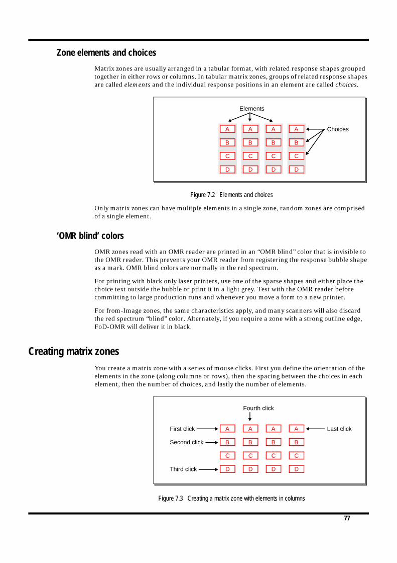
Zone elements and choices
Matrix zones are usually arranged in a tabular format, with related response shapes grouped together in either rows or columns. In tabular matrix zones, groups of related response shapes are called elements and the individual response positions in an element are called choices.
Figure 7.2 Elements and choices
Only matrix zones can have multiple elements in a single zone, random zones are comprised of a single element.
‘OMR blind’ colors
OMR zones read with an OMR reader are printed in an “OMR blind” color that is invisible to the OMR reader. This prevents your OMR reader from registering the response bubble shape as a mark. OMR blind colors are normally in the red spectrum.
For printing with black only laser printers, use one of the sparse shapes and either place the choice text outside the bubble or print it in a light grey. Test with the OMR reader before committing to large production runs and whenever you move a form to a new printer.
For from-Image zones, the same characteristics apply, and many scanners will also discard the red spectrum “blind” color. Alternately, if you require a zone with a strong outline edge, FoD-OMR will deliver it in black.
Creating matrix zones
You create a matrix zone with a series of mouse clicks. First you define the orientation of the elements in the zone (along columns or rows), then the spacing between the choices in each element, then the number of choices, and lastly the number of elements.
Figure 7.3 Creating a matrix zone with elements in columns
A
B
C
D
Elements
ChoicesA
B
C
D
A
B
C
D
A
B
C
D
A
B
C
D
A
B
C
D
A
B
C
D
A
B
C
D
First click
Second click
Third click
Fourth click
Last click

78
When adding OMR zones to an OMR page, response choices will be placed over the nearest response position, indicated by a red dot on the screen, and the interval is calculated as the number of response positions. All other responses in the zone will be similarly placed, at response positions.
For from-Image zones, the actual position is used, the interval to the next position calculated and used to position other responses in the zone. The nearest multiple of the interval is used to calculate the number of responses in the zone and terminating position. Where “snap to grid” is in force, the positions of the responses are centered over the grid position.
To create a matrix zone:
1 Click the Matrix Zone tool button.
2 Click a response position to place the first choice of the first element (the upper-left of the zone).
3 Click the second choice of the first element to define the element’s orientation (along columns or rows) and the spacing between choices in the elements.
4 Click the last choice of the first element to define the number of choices in each element.
5 Click the first choice of the second element to define the spacing between elements.
6 Click the first choice of the last element to complete the zone.
Figure 7.4 Creating a matrix zone with elements in rows
Matrix zones with one or two elements
For matrix zones with less than three choices or elements, click the right mouse button to complete the zone. These are examples:
Figure 7.5 Matrix zones with two and one elements
A
A
A
A
B
B
B
B
C
C
C
C
First click
Fourth click
Last click
Second click
Third click
A
B
C
A
B
C
First click
Second click
Third click
Fourth click, then right
A
B
C
D
First click
Second click
Third click, then right
mouse button to finish
mouse button to finish

79
Matrix Zone with choices and elements in the same plane
Matrix zones with both choices and elements in the same plane may be used to collect counts. The example in Figure 7.6 collects three digits.
Figure 7.6 Choices and elements both in the same plane
Matrix zone properties
You can adjust the settings you defined when you created the matrix zone, such as the number of elements and choices, from the Matrix tab of Zone Object dialog box:
The Horizontal Origin is the response position from the left of the form for OMR zones, alternately is the measurement from the left of the page for from-Image zones.
The Vertical Origin is the response position from the top of the form for OMR zones, alternately is the measurement from the left of the page for from-Image zones.
For each of the elements and choices:
Repeats is the number of elements.
The Count is the number of choices.
Spacing is the number of response positions between elements or choices for OMR zones, alternately is the measurement between choices or elements for from-Image zones.
The orientation of elements or choices may be either Horizontal or Vertical.

80
Figure 7.7 Matrix zone properties
The figure shows the “from-Image” format with measurements; for OMR format, timing mark and response column values are shown. Note that the response shapes are rotated on from-Image Landscape Pages, but not for OMR pages.
Tip: You can quickly resize a matrix zone, changing the number of elements and choices, by selecting the zone and dragging one of its editing ‘handles’.

81
Creating random zones
Random OMR zones are placed on the nearest response position. From-image zones are placed at the pointer and it is recommended “snap to grid” be in force to keep positioning regular (see Figure 7.8).
You create a random zone by clicking each response position where you want to place a choice:
1 Click the Random Zone tool button.
2 Click the response position for the first choice of the zone.
3 Click the response positions to place the remaining choices.
4 Click the right mouse button to define the zone.
Figure 7.8 Creating a random zone
Assigning text to choices
When designing OMR forms, it’s good practice to place text next to each choice so the person filling out the form knows which choice to mark, and FoD-OMR provides many options for automatically applying text to choices.
First click A
D
B
C
Second click
Third click
Fourth click EFifth click, thenright mouse buttonto finish

82
To set up text for choices:
Select the zone, then click the right mouse button and select Properties from the shortcut menu. Alternatively, with the zone selected, press CTRL+E or click the Properties tool button.
Figure 7.9 Labelling choices
You can select from the following range of standard text by clicking the Standard choices button:
Letters (upper and lower case) for each choice, starting with ‘A’ or ‘a’.
Numbers for each choice in ascending order, starting with ‘0’ or ‘1’.
Months for labelling each choice with the 3-letter month (‘Jan’, ‘Feb’, etc.).
Binary encoding for expressing numbers. Typically, these are serial numbers encoded on the form in one of two available encoding schemes.
Binary encoding is an alternate to bar codes. Bar codes are more reliable and generally much smaller than an OMR matrix or binary encoding scheme. Check the manufacturer’s specification to determine what bar code symbologies and densities are read by your equipment and software and test before committing to production volumes.
Choices for using one of several Yes-or-No, True-or-False labelling styles.
Spanish giving a list of the above choices for Letters and Months.
The 1-2-4-8encoding
The 1-2-4-7encoding
scheme scheme

83
Positioning text and response shapes
Different response shapes are available. If the response position appears on a background other than white, such as a rectangle filled with solid colour, or frame stripes, click White filled to clearly mark the response position.
You can position text on the first, last or all elements by selecting from the Text appears on list as well as offsetting the text from the center of the response using Offset from mark. Negative values offset left and top respectively.
The matrix zones in Figure 7.10 have labels on the first element, with the horizontal and vertical positions shifted (a negative adjustment) so the labels appear outside the choice positions.
Figure 7.10 Positioned text on matrix zones
Decorating zones
With FoD-OMR, you can easily add borders, dividers and shading to zones to improve the readability and selection of zone choices.
By clicking the Frame tab of the Zone Object dialog box, you can set the style for borders, dividing lines, and alternating stripes.
Border dimensions
If you add a border to a zone, you can set the distance of the border from the zone choices, and the thickness of the line, from the Border tab.Uncheck the Auto offsets box to set custom border dimensions.
Figure 7.11 Border

84
Border corners
You can round each of the corners of the border and set the radius of the rounded corners by unchecking the Auto-size box on the Corners tab.
Figure 7.12 Corners
Stripes
Adding alternating stripes to large matrix zones greatly eases filling out your form. You can orient the stripes along elements or along choices, and shade the colour of the stripes in your OMR scanner’s blind color range (see “‘OMR blind’ colors” on page 7-77).
Figure 7.13 Stripes and Dividers

85
Format
By selecting the Format tab, you can arrange the text relative to the responses. This operates in conjunction with the Text Offset from Mark (see “Positioning text and response shapes” on page 7-83) and gives you precise control over placement and appearance of response text.
From the Format tab, you can set the alignment of text, the distance between lines (for text that spans more than one line) and the size of tab spaces, for text with tabs.
Figure 7.14 Alignment
The line spacing is relative to the font size, but can be changed to an exact measurement by selecting Exact from the Line Spacing list, and typing a value for the distance between lines.
Figure 7.15 Spacing
Aligned to the lefthorizontally and to
the center vertically.
Aligned to the center vertically and
horizontally.
Aligned to the righthorizontally and to the
center vertically.
By default,
choice text is
set to one line
spacing.
You can change line
spacing by selecting
an option from the list,
or by specifying the
exact line spacing.

86
Font
From the Font tab, you can select font type, orientation of the font and color.
Figure 7.16 Font attributes
Resizing zones and moving choices
As you edit your form and add zones, you may find you need to change the size of a zone, or the spacing between elements and choices, particularly to accommodate text. FoD-OMR provides a convenient way to change the dimensions and resize zones.
Matrix zones
To change the dimensions of a matrix zone:
1 Select the matrix zone.
2 Drag one of the choices in the zone’s top-left corner to change the spacing along that axis.
Orientation is in degrees

87
3 Drag one of the zone’s editing handles to increase or decrease the number of choices and elements.
Figure 7.17 Changing Matrix Zones
Random zones
While you cannot add new choices to a random zone, you can easily change the response position of each zone.
To change the position of random zone choices:
1 Select the zone.
2 Double-click the choice to move. The mouse cursor changes to a hand indicating editing mode.
3 Drag the choice to its new position.
4 Repeat steps 2 and 3 with any other choices to be moved.
5 Right-click the mouse button or press Esc to leave editing mode.
Figure 7.18 Moving Random Zones
For from-Image forms, it is good practice to have “snap to grid” on before attempting to move random responses as the move will snap to the grid.
Move this choice to adjustthe horizontal spacing.
Move this choice to adjustthe vertical spacing.
Move this choice to shift thezone to a new response position.
Drag one of the zone’s handlesto change the number of elementsor choices.
Drag the choice to a newresponse position.double-click a choice to move it...
With the zone selected,

88
Duplicating zones with the “CTRL” method
Zones may be duplicated in several ways, the most appropriate for OMR zones is to duplicate them with the “CTRL” method. This is a short-cut “Paste at”. For from-Image zones, first ensure that “snap to grid” is on.
Select the zone (or zones) to be duplicated.
With CTRL pressed, select the current object, continue to hold down Mouse Left and a copy of the selection will be “dropped” when you release the pointer. This can be done repetitively and with multiple zones for very fast setup of identical fields (such as test questions).
This technique can be applied to any graphic object.
Combining Zones
You can combine zones to good effect by drawing the frame and instructions or questions with a "null" response, then overlaying a zone with the choice responses. See below.
Figure 7.19 Overlay Matrix Zones
Figure 7.20 Overlay Matrix Zones

89
CREATING CONSTRAINED HANDPRINT FIELDS
8 Constrained Handprint fields are used to collect hand printed characters, and are used on from-Image forms. The technique has error rates of around 10% per character for alphanumerics and around 3% for numeric fields in the absence of other validation criteria such as check digits or check totals, which are highly recommended.
About constrained handprint fields
Constrained handprint fields capture a fixed number of characters with individual bounding boxes for each character. Most constrained handprint fields are printed in the “blind” color for the scanner.
To draw a constrained handprint field:1. Click the Constrained Handprint tool button.2. Draw the frame for the object.3. The Settings Tab within the Constrained Handprint is shown, with the number of charac-
ters, which can be adjusted. OK to complete the field.
Figure 3.1 Constraint handprint settings
Constrained handprint properties
You can adjust the setting defined when you created the constrained handprint field by double-clicking or by pressing mouse right and selecting Properties tool button.

90
Settings
The Settings tab (Figure 3.1), defines the physical dimensions of the field.
Format
On the Format tab, define the appearance of the field.
Figure 3.2 Constraint handprint format
Position
On the Position tab, define the position of the field. The bottom “locked” portion of the window shows the overall width and height of the field.

91
WORKING WITH GRAPHICS
4 This chapter describes the tools available in FoD-OMR to add lines and rectangles, text, barcodes and pictures, and arrange the objects on your form.
Preparing your workspace
Before beginning a form design session, it is recommended you set up your workspace to include your preferences.
Setting preferences
To set the units FoD-OMR uses when displaying measurements, select Options from the Tools menu.
Figure 4.1 Options
Select your preferred measurement from the Measurement units list.
(We recommend 1/300th measurements as these are round numbers for OMR channel spacing: 50 dots for 6 per inch and 60 dots for 5 per inch. Their smaller choices are respectively 25 and 5 dots and 30 and 6 dots).
The object grid
As well as the response grid, made up of the response positions on the form, FoD-OMR also has an object grid, to guide you when aligning objects. When enabled, the object grid sets the points at which a resized or drawn object ‘snaps’ to the grid.

92
To set up the object grid, select Object Grid from the Tools menu.
Figure 4.2 Grid
You can set the precise offset of the origin (top-left corner) of the object grid and the grid spacing. For manipulating OMR objects and their frames, set both Align with OMR Grid and Full OMR Grid.
Click the Show grid button to view the object grid (in blue). Click the Snap to grid button to enable the object grid.
Nudge distance
You can fine-tune the placement of graphics objects by nudging them into place with the keyboard arrow keys. The nudge distance works independently of the object grid.
Select a nudge increment by clicking the Nudge tool button.
Figure 4.3 Nudge
The Nudge type list has many preset distances, or you can set your own Horizontal and Vertical distances.
The placementof the top-leftcorner of thegrid relative tothe page.
The distancebetween gridpoints.

93
Difference between two objects
If two objects are selected on your form, the additional choice Difference between selected objects also appears.
Adjusting the zoom
Four zoom settings control how large or small the page appears in the workspace. These are available on a floating toolbar or through the Zoom dialog box.
To view the zoom toolbar:
Click the Zoom tool button.
Figure 4.4 The Zoom toolbar
To zoom to a selectable size, click the tool button and drag the mouse around the objects to magnify. The zoom is adjusted to the selected size.
All of the available zoom options can be viewed by selecting Zoom from the View menu.
Figure 4.5 Zoom options
Drawing graphics objects
To draw objects such as lines, circles and rectangles, you select a tool from the toolbar, click and hold down the left mouse button on your form, and drag the mouse to size the object.
Zoom to aselectable size
Select a zoompercentage
Zoom to thepage width
View thewhole page

94
Lines
FoD-OMR provides three tools for drawing horizontal, vertical or diagonal lines.
When drawing or moving a diagonal line:
Hold the CTRL key down whilst using the mouse to move the end point of the diagonal line. This will round the angle of the line to an increment of 15 degrees
Hold the SHIFT key down whilst using the mouse to move the midpoint of the diagonal line. This will round the angle of the line to an increment of 5 degrees
To edit the line properties, click on the line to select it and then choose Properties from the Edit menu. Alternatively, double click on the appropriate line.
On the Format tab, you can edit the line’s Pattern, Width, Color and End Cap.
There are three End Cap options:
Round
Square
No End Cap
Figure 4.6 Shape object (line)
Squares and rectangles
The rectangle tool is used to draw both squares and rectangles. You can also draw squares or rectangles with rounded corners.
To draw a square, hold down the CTRL key when dragging the mouse to size the object.
Draw a horizontal line
Draw a vertical line
Draw a diagonal line
Round
Square
No End Cap
Draw a rectangle or square.
Draw a rectangle or square with rounded corners.

95
Circles and ellipses
The ellipse tool is used to draw both circles and ellipses.
To draw a circle, hold down the CTRL while dragging the mouse to create the object.
If you hold down the Shift key when sizing a rectangle or ellipse, the object is drawn from its centre, as shown in the following diagram.
Line and fill styles
After creating graphics objects, you can apply different line styles and fill features to enhance their appearance. You can control the weight (thickness) and color of the lines that make up objects and can select the pattern and color of filled objects.
To change the line and fill styles for graphic objects, select the object and click the Properties button, or type CTRL-E.
From the Format tab, you can select a pattern and width for the outline of the object, and the brush pattern for filled objects such as circles and squares. The color for the outline and brush can also be selected.
Figure 4.7 Shape Object (box, oval)
Draw a circle or ellipse.
Drag Release

96
The Figure 4.7 above shows some of the available patterns you can use to fill solid objects such as rectangles or circles.
Adding text
Each text object on a FoD-OMR form is contained within a text frame, from which the alignment and orientation of the text itself is calculated.
To add a text object to a form, select the Text tool button and draw the text frame on the form. When you have sized the text frame, the Text Object dialog box opens.
Figure 4.8 Text Object
Definition
The Definition tab contains the actual text that appears in the frame, as well as tools for linking to records in a data file. More information about linking text is available in Chapter 4, “Merging Data from Files”.
If you type more text than can fit in the text frame, the frame automatically resizes to include all the text.
Linked text
FoD-OMR has a powerful feature that integrates information from data files into your form. The source of your text object can be either fixed (the text from the Definition tab is constant for each form) or can be linked to records within a data file (such as application or spreadsheet output).
To extract information from data files, you link text from the definition tab to external data records. This feature is fully discussed in Chapter 4, “Merging data from files”.

97
Format
From the Format tab, you can set the properties of the text within the text frame. The Alignment is the position of the text relative to the frame. Text can be horizontally aligned to the left, centre and right, but also to a decimal point. When decimal alignment is selected, the text is aligned against the first decimal point that appears on a line.
Figure 4.9 Decimal alignment
For text frames that contain large amount of text, you can also set the line spacing and word wrap properties for the frame, as well as the distance of the Tab stops.
Figure 4.10 Setting the format of text within a text frame

98
Font
The Font tab on the Text Object dialog box has the settings for the appearance of text within the frame.
As well as the typeface, style and size of the font, you can also set the orientation of the text within the frame, and the text color.
Figure 4.11 Setting Font properties
Once you set up the properties of your text object, the text frame is resized to automatically enclose the text entered on the Definition tab.
Adding barcodes
Barcodes are useful to add to your form, particularly if your OMR scanner has a barcode reader. For most scanners with barcode readers, barcodes must be printed so that their lines are at right angles to the long edge of the form.
Like text objects, barcodes can either have a fixed value or a value linked to a field in a data file record and merged when the form is printed.
For example, if you had a file containing a series of numbers you wish to encode as barcodes on your forms, you can create a single barcode object and instruct FoD-OMR to extract the data for that barcode from the data file. Before linking to information in a data file, you need to set up the data file records (where the data in the file can be found). More information on linking to data in files can be found in Chapter4, “Merging data from files”.

99
To add a barcode object to a form, select the Barcode tool button and draw the frame on the form. When you have sized the barcode frame, the Barcode Object dialog box opens.
Figure 4.12 The Barcode Object dialog box
Definition
From the Definition tab, you can select the Symbology from many encoding styles in the list, and in the Text box, type the value represented by the barcode.
Before the barcode is created, the encoded value is formatted according to the barcode symbology. If your Text value cannot be encoded by the selected symbology (for example, letters cannot be encoded by ‘Code 2 of 5’), the barcode object is not created.
Format
From the Format tab, you can select whether to display the text value of the barcode, the text position, and the orientation of the barcode.
Figure 4.13 The barcode format
100
If you display the text, you can set the font and style from the Font tab.
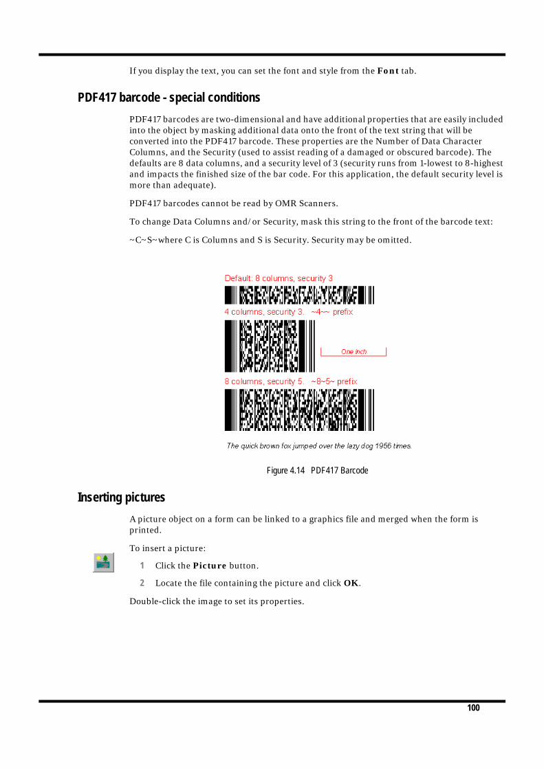
PDF417 barcode - special conditions
PDF417 barcodes are two-dimensional and have additional properties that are easily included into the object by masking additional data onto the front of the text string that will be converted into the PDF417 barcode. These properties are the Number of Data Character Columns, and the Security (used to assist reading of a damaged or obscured barcode). The defaults are 8 data columns, and a security level of 3 (security runs from 1-lowest to 8-highest and impacts the finished size of the bar code. For this application, the default security level is more than adequate).
PDF417 barcodes cannot be read by OMR Scanners.
To change Data Columns and/or Security, mask this string to the front of the barcode text:
~C~S~where C is Columns and S is Security. Security may be omitted.
Figure 4.14 PDF417 Barcode
Inserting pictures
A picture object on a form can be linked to a graphics file and merged when the form is printed.
To insert a picture:
1 Click the Picture button.
2 Locate the file containing the picture and click OK.
Double-click the image to set its properties.

101
Figure 4.15 The Picture Object dialog box
To merge the picture from the file when the form is printed, click the Linked check box. To be able to adjust the dimensions of the picture, check the Scalable check box. Please note, Linked pictures will slow production at runtime, especially where the image has been scaled.
You can also set the image location on the form and scale the picture manually from the Position tab, where you can enter the precise position and dimensions for the picture. If you check the Lock aspect ratio box, the dimensions are scaled proportionally to retain the ratio of the picture’s width to its height. This is useful for resizing a picture to a specific width or height without distorting the image.
Figure 4.16 Setting the pictures place and dimensions

102
Arranging objects on your form
FoD-OMR offers many ways to arrange your form to enhance its appearance and usability.
Undoing and repeating actions
As you arrange the objects on your form, remember to use the Undo and Redo tools to correct mistakes.
Cut and Paste
You can use the Cut, Copy, Paste and Paste At buttons on the toolbar to duplicate a selected object or group of objects.
When pasting an object from the clipboard, you can select the location for the new object by clicking the Paste at button and selecting the location for the upper-left corner of the object.
The Duplicate command (CTRL+D) in the Edit menu makes a copy of the selected object or group of objects and slightly offsets it from the original.
You can also duplicate and item using the CTRL key and drag and drop. While holding the CTRL key down click the object to select it. Holding the left mouse button down drag the new object to a different location.
Moving and resizing objects
You can easily move an object by selecting it with the mouse and dragging the object to a new location on the form.
When moving an object, you can Nudge it by using the keyboard arrow keys for finer control of its placement. See “Nudge distance” on page 92 for more information.
Grouping and ungrouping objects
By grouping several objects together, you can control them as a single object. This is useful when you need to move, resize, or align them as a single object. You can combine a group with other objects, or even other groups.
To group objects:
1 Select the objects by holding down the Shift key and clicking each object. A set of handles appear around the selected objects.
Cursor changes to a cross hair with a plus sign

103
2 Choose Group from the Edit menu, or type CTRL+G. A set of handles appear around the grouped objects.
To ungroup objects, select the grouped objects and select Ungroup from the Edit menu. Handles appear on each object in the group. If there appears to be more grouped objects in the group, you may have to select the remaining objects and apply the ungroup command again.
You can resize a single object or group of objects on your form in different vertical and horizontal proportions by dragging one of the object’s editing handles with your mouse.
Unlike other objects, barcodes shift in fixed sizes when dragged to increase or decrease the barcode density. Each fixed size adds or subtracts one pixel to the small bar with corresponding changes to all of the other bars and spaces.
Resizing text
Text that appears within text or barcode objects can be resized using the Increase Font and Decrease Font tool buttons. The font of your object decreases by one point each time you click on this tool button.
Multiple Object Sizing
You can resize objects by using the Size function, which adjusts the scale of objects according to other objects in the selection. For example, in Figure 4.17, the grey rectangle was resized to the same dimensions as the white rectangle.
Figure 4.17 Multiple object sizing
To size objects, select the objects by holding the Shift key and clicking each object, then select a Size option from the Tools menu.
Drag an editing handleto scale an object.
Select objects to beresized...
...apply the horizontaland vertical sizing required.

104
Moving angled lines
You can move the either handle of an angled line to change its length and angle. Two special keys can be used to control the angle. Pressing CTRL while moving the handle rounds to a 15 degree angle, while pressing SHIFT rounds to a 5 degree angle for finer adjustment.
Aligning objects
With FoD-OMR’s alignment tools, you can accurately line up rectangles, lines and other graphics objects. There are tools for aligning parts of an object (top, bottom, left and right), or a group of objects to other objects, and you can align selected objects exactly between the top and bottom or left and right of other objects.
Additionally, with the stretch alignment tool, you can align the dimensions of objects, resizing them.
To view the alignment tool panel, click the Alignment button.
Figure 4.18 The alignment tool panel
The following diagrams illustrate how you can use the alignment panel tools.
To align... Do this
...the top of the selected object to another, use this tool
Select this to enable
stretch alignment.
Aligns the bottom of
the selected object to
a point.
Aligns the top of the
selected object to
a point.
Aligns the right side
of the selected object
to a point.
Aligns the selected
object between two
points horizontally
Aligns the left
side of the selected
object to a point.
Closes the tool
panel.
or vertically.
Select the object you want aligned...
...and click the top ofthe second object...
...the selected objectsaligns itself perfectly to the top of the secondobject.

105
...the bottom of the selected object to another, use this tool
...the selected object between the top and bottom of another, use this tool
...the selected object between the left and right sides of another, use this tool
...the left side of the selected object to another, click this tool
To align... Do this
Select the object you want aligned...
...and click the bottomof the second object...
...the selected objectsaligns itself perfectly to the bottom of thesecond object.
Select the object you want aligned...
...and click the top and bottom lines to align to.
...the selected objectsaligns itself perfectly between the top andbottom of the secondobject.
Select the object you want aligned...
...and click on the left and right lines to align to.
This object is aligned exactly between the
...of the two lines you clicked.
left and right...
Select the object you want aligned...
...and click on the left sideof the second object to be
The left side of this object is aligned exactly...
...to the line you clicked.
aligned to...
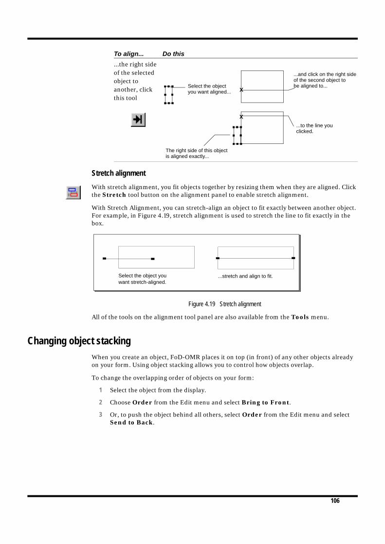
106
Stretch alignment
With stretch alignment, you fit objects together by resizing them when they are aligned. Click the Stretch tool button on the alignment panel to enable stretch alignment.
With Stretch Alignment, you can stretch-align an object to fit exactly between another object. For example, in Figure 4.19, stretch alignment is used to stretch the line to fit exactly in the box.
Figure 4.19 Stretch alignment
All of the tools on the alignment tool panel are also available from the Tools menu.
Changing object stacking
When you create an object, FoD-OMR places it on top (in front) of any other objects already on your form. Using object stacking allows you to control how objects overlap.
To change the overlapping order of objects on your form:
1 Select the object from the display.
2 Choose Order from the Edit menu and select Bring to Front.
3 Or, to push the object behind all others, select Order from the Edit menu and select Send to Back.
...the right side of the selected object to another, clickthis tool
To align... Do this
Select the object you want aligned...
...and click on the right sideof the second object to
The right side of this object is aligned exactly...
...to the line you clicked.
be aligned to...
Select the object you ...stretch and align to fit. want stretch-aligned.
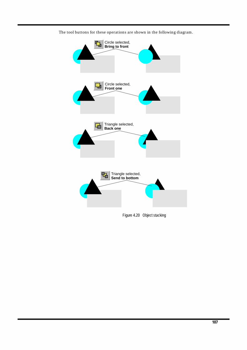
107
The tool buttons for these operations are shown in the following diagram.
Figure 4.20 Object stacking
Circle selected,Bring to front
Circle selected,Front one
Triangle selected,Back one
Triangle selected,Send to bottom

108
MERGING DATA FROM FILES
5 You can insert data from files into zone, text and barcode objects on your form, and dynamically merge the data when the form is printed. This is similar to the ‘mail merge’ feature found in word processors, but considerably more powerful.
Data files can be any form of plain text file, and usually contain the output of database or spreadsheet applications.
There are two main ways to configure FoD-OMR to use data files:
If the first row of your data file contains the field name, FoD-OMR can use this row to identify each column and extract the information to the relevant data field. This option is only available when using delimited (sometimes called CSV) files. See “Printing forms with merged data” on page 117. on this option.
Where the data is in a fixed field format or a delimited file without headings, FoD-OMR objects are set up to reference a specific data field when the form is printed.
Preparing your data files
FoD-OMR can use data files in two distinct ‘formats’:
Fixed data files have the same data field always at the same location on each line in the data file. Fields in fixed data files have two properties: a start position and a length (in characters).
Delimited data files have their fields separated by a character known as a delimiter. When the first row of your data file contains the field names FoD-OMR can use this row to identify each column and extract the information to the relevant data field.
Fields are grouped together in records, which are terminated by the line feed character. For each record in a data file, FoD-OMR extracts the data from its fields and prints one form.
Figure 5.1 shows a data file representing the same data in fixed format, delimited format with headings and separated format without headings. Delimited files with headers offer the most flexibility and should be preferred as a data source. The ability for the field names to be carried as headers in the first record enable both simpler form design and ease of data manipulation.

109
The delimited format uses the comma as the delimiter and double quotation marks surround text items. The double quotation marks are known as the text qualifier as they indicate text fields.
Figure 5.1 Data file formats
When merging data from files, you can change the appearance of your form without impact on the structure of the data file. Similarly, you can change the structure of the data file without modifying the form’s layout.
Defining fields
When a form is printed that contains objects that merge data from a file, FoD-OMR opens the file, and extracts the required data from defined fields. The number of lines in the file (records) determines the number of forms that are printed.
When you define the structure of your data file, each field is labelled, and the information contained in the fields can be displayed in several places on your form, and in different formats (such as both a barcode and a matrix zone).
Before you define your fields, it is recommended you have a sample data file handy to reference the fields in each record.

110
Defining fields for delimited data formats
To define fields for delimited data formats, select External Data from the Tools menu to open the Field Definitions dialog box.
Figure 5.2 Setting up fixed data field definitions
1 Click New to create a new field. If this is the first field for a new form definition, you will need to select the type of input data file.
2 Type a Name for the field. If you are using a delimited data format with headings enter each column heading as a field name. At merge time FoD-OMR will identify each column using these headings and extract the information into the fields on the form.
3 You do not have to set a maximum length for fields in a delimited data file as these are automatically detected by FoD-OMR, but it is good practice to enter the length as an aid to defining the correct length of the field.
Click the New button tocreate a new field definition
Enter a field name

111
Defining fields for fixed data formats
To define fields for fixed data formats, select External Data from the Tools menu to open the Field Definitions dialog box.
Figure 5.3 Setting up fixed data field definitions
1 Click New to create a new field. If this is the first field for a new form definition, you will need to select the type of input data file.
2 Type a Name for the field. This label is then available as a link selection.
3 If the field is in a fixed data file, enter a Length for the field and a Start position if the field does not immediately follow the preceding one. The Start position is automatically updated when more fields are defined.
Editing fixed fields
If your data is extracted from a fixed data file, you can easily change the positions of the fields in each record by selecting the field and clicking the Edit button.
To change the start position of a particular field, and automatically update the start positions of all the fields that follow it, click the Shift button and enter an offset to increase or decrease the start position.
Figure 5.4 Shifting the start position of a field
Click the New button tocreate a new field definition
Type a field nameand enter its startposition and length

112
Linking to fields
Once you have defined your fields, they are available for linking to text, barcode and zone objects (see Figure 5.5).
Figure 5.5 Linking fields
To use the data extracted from the fields in your form, you link the text from the Definition tab of zone, text or barcode objects.
To create a link to a field:
1 Create a text object on your form.
2 From the Definition tab, type in some sample text for the object.
3 To link part of your sample text to a field in your data file, select the sample text to be replaced and click Link selection. To link the entire source of an object to a field, click Link all.
4 Select the defined Field or click the Finder button to create a new field definition.
5 The linked text is underlined in boldface on the Definition tab, and the link is added to the Linked records list (see Figure 5.6).
Last Name
First Name
Age
Student Number
Fields in each recordare defined and labelled
Labelled fields arethen available forlinking
FoD-OMR definessome fields that arealways available
When a field islinked, its iconchanges

113
Figure 5.6 A text object displaying the page number
As well as the fields you define from your data file, FoD-OMR makes the following fields available for your form:
Page is the current page number of this form in the batch print run.
Next page and Previous page are reserved for booklet printing.
Date is the date the form is printed.
To change the properties of the link, select the link from the list and click the Edit link button. To remove the link altogether, click Delete link.
Masking
When you link to a field, you can format the data that is extracted from the file in one of many available styles.

114
Masking dates
When you use date masking, you select the Input format of the date (the order of the day, the month and the year) and an Output format (how the date appears). You can also change the character used as a date separator and whether the year is two digits or four digits.
If the date field contains two separators (any non-numeric characters such as ‘/’ or ‘-’), FoD-OMR automatically formats the date field.
If there are no separators, the date field must be either 6 or 8 characters. If it is 6 characters, a 2-digit year is used, whereas a 4-digit year is used for fields of 8 characters. If you mask non-separated date fields (such as ‘31122002’), be sure your day and month fields are ‘zero prefixed’ - using ‘01’ instead of ‘1’.
Masking currency
FoD-OMR provides many ways of formatting currency values: you can create your own formatting Amount/Numeric style, you can use the Wordy style to write out the amount in words, or format the amount as Cents.
All currency formats have a setting for detecting decimal fractions. If Use decimal separator is selected, FoD-OMR searches the data field for a decimal place and formats the amount on the left side of the decimal as ‘dollars’ and the amount on the right side as ‘cents’. If no decimal place is found, the amount is formatted as whole dollars.
If Always assume two decimals is selected, FoD-OMR ignores any separators and formats the last two digits as ‘cents’ and all other digits as ‘dollars’.
031602
March 16, 2002
Data in date field,
03162002 16 Mar 2002
}0316023/16/02
3-16-2002
Output format is 7 Jan 1997Year is Four digits
Output format isJanuary 7, 1997Year is Four digits
Input format isMonth-Day-Year
Data in date field,Output format is 01/07/1997
Input Format isYear-Day-Month
Year is Four digits200203162002.3.16
02031602-03-16} 03/16/2002
Short date separatoris ‘/’

115
Amount/Numeric
With this style, you exactly define the appearance of a currency amount.
Currency
From this tab, you can select the character used as the currency symbol, its placement on the left or right side of the amount, and whether to separate the symbol from the numbers with a space.
Separators
From this tab, you can select the characters used to separate thousands and decimals.
Numbers
From this tab, you can design how negative numbers are formatted. For the Negative sign you can represent negative numbers as a debit and positive numbers as a credit, use a the ‘-’ character or surround the amount in brackets. An Extra space can separate the negative symbol from the amount.
You can increase the precision of the decimal numbers that are formatted in the Number of decimals box.
Figure 5.7 Designing a custom currency format
If you are going to re-use your custom formatting, click Save and name the formatting style. The style remains available by selecting Custom from the Mask list.
-10234567 ($102,345.67)
Amount in data field
002305.30- $2,305.30Cr
Negative symbol is (12)Assume two decimals
Negative symbol is 12CrUse decimal separator

116
Custom masks can also be created, edited and deleted under the Options menu available from the Tools menu. A list of the currently defined custom masks appears on the Custom tab.
Figure 5.8 Custom mask
Wordy
The Wordy style writes out the amount in words.
Units
The Units style takes the first character of the amount in the data field and represents it as a word.
Cents
This style only displays the decimal portion of the amount.
37.56 THIRTY SEVEN
Amount in data field
3756 DOLLARS AND 56 CENTS
Wordy styleAssume two decimals
3 THREE
Amount in data field Units style
3756 56 CENTS
Amount in data field
3.756 76 CENTS
Cents styleAssume two decimals
Cents styleUse decimal separator

117
Printing forms with merged data
When you print your form containing linked objects, you select the data file to merge for the current print run. FoD-OMR opens the file and examines the first record (line), extracting the data for its fields. Linked objects are created with the data in the fields and the form is printed.
The process repeats for each record in the file, with one record corresponding to a single form.
Click the Print button to open the Print dialog box and select the Merge tab.
Figure 5.9 The Print dialog box
From the Merge tab, click Browse to locate the data file. FoD-OMR accepts two different Input types for data files:
1 FLIPS 3.x fixed size records is for fixed data files.
2 Separated values is for separated data files. Click Options to select the delimiter used between fields:
Figure 5.10 Options for delimited files
Some databases and spreadsheets enclose text fields in a single or double quotation mark. FoD-OMR can remove this character when extracting text if you select the Text qualifier used.
Most databases and spreadsheets also put the name of each field in the first record of their file, like a table header. If your data file is formatted in this way, you can select First row contains field names. When this option is checked FoD-OMR will use the first row to identify each column and extract the information to the relevant data field.

118
If your data file does not have column headers the order of extraction is determined by the start position of each data field. The first column in the data is extracted to the first data field, the second column to the second data field and so forth. For more information on defining the start position of a data field see “Defining fields” on page 5-109.
Click Print to merge the files and print them, or Preview to view a sample of the print run.

119
KNOWN ISSUES
A Outlined below are known issues which have been encountered while using FoD-OMR.
Smooth Edges
When designing an OMR form the objects, such as response shapes, may appear incomplete. This is caused by a problem with how windows displays TrueType fonts.
Figure A.1
To correct the problem you will need to turn on the Smooth edges of screen fonts option.
In Windows 2000, this setting can be found on the Effects tab of Display Properties. Display Properties can be accessed from the Control Panel.
incomplete Response Shapes
Smooth edges of screen fonts option

120
In Windows XP, you can access this option from the Appearance tab of Display Properties, which is under the Control Panel. Click the Effects button and ensure that Use the following method to smooth edges of screen fonts is checked and set to ClearType.
When this option is selected the problem will be resolved.
Effects button
Smooth edges of screen fonts option
complete response shapes

121
BATCH PRINTING
B FoD-OMR accepts command-line arguments with which you can automate batch printing and control the data files merged with forms when printing.
Command line arguments
Use one of the following command line formats:
FoDOMR
Creates a new file.
FoDOMR <formname>
Opens the form file.
FoDOMR <formname> /p
Prints the form file to the default printer.
FoDOMR <formname> /pt <printer> [driver port]
Prints the form file to a specific printer, optionally specifying a printer driver and port.
FoDOMR /po
When used with either the /p or /pt arguments, allows you to further specify the fol-lowing options.
For more information about how data is merged during batch printing, see Chapter 4, Merging Data from Files.
Print option Description Default value
copies=xxx Number of copies 1
collate Collate forms when printing Do not collate
out=<filename> Print to file Print to default printer
merge=<filename> Merge from data file No default data file
delimited Data file is a separated file Data file is a fixed file
delimiter=x Delimiter used to separate fields in a separated data file
Comma
qualifier=x Text qualifier, if used in a separated data file
Double quote
names The first row of the delimited file contains field names
First row does not contain field names

Index-i
INDEX
A
Aligning Objects 104Between left and right 105Between top and bottom 105Bottom 105Left 105Right 106Top 104
alignment 97stretch 106
amount 115arranging objects 102aspect ratio 101
B
barcodes 98blind colors 77
C
channel bank 10channels 14choice text 81
font 86positioning 83
choices 81standard 82
currency 115
D
data filesfixed 108separated 108
decrease font 103definition 96, 99, 112Design workspace 1, 5, 6, 91duplicate 102
E
external data 110, 111extra space 115
F
fields 108defining 109editing 111length 110linking 112start position 110
fillpatterns 96styles 95
font 86, 98format 85, 95, 97, 99
G
griddefinition 10see also response grid
group 103
I
increase font 103
L
line spacing 97line styles 95link selection 112linked pictures 101linked text 96, 112
M
marks, see timing marksmasking 113
cents 116currency 114dates 114units 116wordy 116
matrix zones, see zonesmeasurement 91merge 117

Index-ii
N
negative sign 115nudge 102
distance 92number of decimals 115numbers 115numeric 115
O
object grid 91object properties 95objects
aligning 104arranging 102grouping and ungrouping 102moving and resizing 102sizing 103stacking 106
OMR blind colors 77order 106orientation 9origin 92
P
PageOrientation 6Size 6
paper size 6pictures 100portrait orientation 6position 101preferences 91preview 118printing 117properties 95
R
random zones, see zonesrecords 108response grid 9, 13–14response shapes
positioning 83
S
scalable pictures 101separated values 117separators 115
standard choices 82status bar 6stretch alignment 106symbology 99
T
tab stops 97text 96
alignment 97definition 96font 98format 97linked 96resizing 103
text qualifier 109, 117timing mark
positions 14–15timing marks 11, 13timing track 9, 10, 14Tool buttons 5Tools
alignment 104barcode 99bring to front 106circles 95decrease font 103duplicate 102ellipses 95External Data 110, 111increase font 103lines 94object grid 92pictures 100properties 95rectangles 94redo 102send to back 106squares 94stretch alignment 106text 96timing lines 13undo 102zoom 93
U
ungroup 103
W
word wrap 97

Index-iii
Z
zone properties 79–80zones
borders 84creating 77–80, 81decorating 83
elements and choices 77frame 83matrix 76random 76resizing 86stripes 84
zoom 93