fittings and accessories - skf...high-pressure cutting sleeve unions acc to iso 8334-1 38...
TRANSCRIPT

For oil, fluid grease and grease lubrication systems and general use
Fittings and Accessories
Intr
oduct
ion Introduction 2
Solderless pipe union with tapered sleeve 10
Solderless pipe union with cutting sleeve 38
Quick Connectors 82
Manifolds 98
Tubes and Hoses 100
Fixing material 116
Couplings 122
Valves 126
Navigation
Adapters 72
2
Intr
oduct
ionPressure gauges 134
Refill pumps 162
Reservoirs and trays 138
Tools 152
Lubricating nipples 142
Filters 146
Brushes 150
3
Intr
oduct
ion
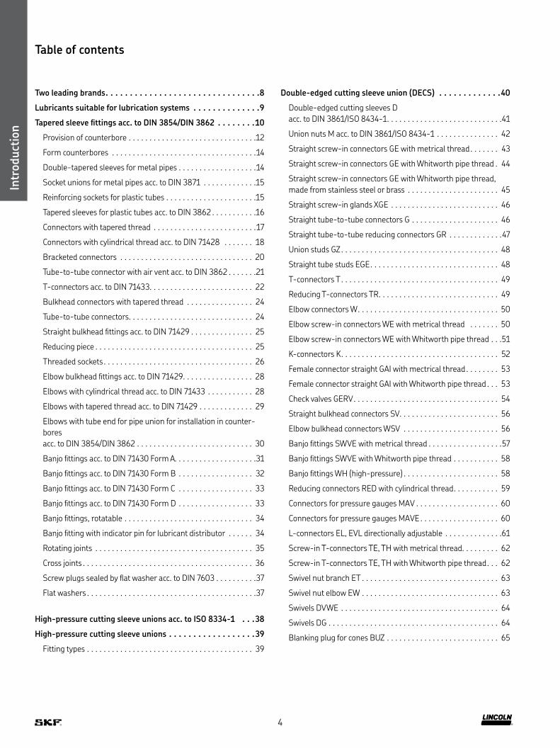
Table of contents
Two leading brands 8
Lubricants suitable for lubrication systems 9
Tapered sleeve fittings acc to DIN 3854/DIN 3862 10
Provision of counterbore 12
Form counterbores 14
Double-tapered sleeves for metal pipes 14
Socket unions for metal pipes acc to DIN 3871 15
Reinforcing sockets for plastic tubes 15
Tapered sleeves for plastic tubes acc to DIN 3862 16
Connectors with tapered thread 17
Connectors with cylindrical thread acc to DIN 71428 18
Bracketed connectors 20
Tube-to-tube connector with air vent acc to DIN 3862 21
T-connectors acc to DIN 71433 22
Bulkhead connectors with tapered thread 24
Tube-to-tube connectors 24
Straight bulkhead fittings acc to DIN 71429 25
Reducing piece 25
Threaded sockets 26
Elbow bulkhead fittings acc to DIN 71429 28
Elbows with cylindrical thread acc to DIN 71433 28
Elbows with tapered thread acc to DIN 71429 29
Elbows with tube end for pipe union for installation in counter-
bores
acc to DIN 3854/DIN 3862 30
Banjo fittings acc to DIN 71430 Form A 31
Banjo fittings acc to DIN 71430 Form B 32
Banjo fittings acc to DIN 71430 Form C 33
Banjo fittings acc to DIN 71430 Form D 33
Banjo fittings, rotatable 34
Banjo fitting with indicator pin for lubricant distributor 34
Rotating joints 35
Cross joints 36
Screw plugs sealed by flat washer acc to DIN 7603 37
Flat washers 37
High-pressure cutting sleeve unions acc to ISO 8334-1 38
High-pressure cutting sleeve unions 39
Fitting types 39
Double-edged cutting sleeve union (DECS) 40
Double-edged cutting sleeves D
acc to DIN 3861/ISO 8434-1 41
Union nuts M acc to DIN 3861/ISO 8434-1 42
Straight screw-in connectors GE with metrical thread 43
Straight screw-in connectors GE with Whitworth pipe thread 44
Straight screw-in connectors GE with Whitworth pipe thread,
made from stainless steel or brass 45
Straight screw-in glands XGE 46
Straight tube-to-tube connectors G 46
Straight tube-to-tube reducing connectors GR 47
Union studs GZ 48
Straight tube studs EGE 48
T-connectors T 49
Reducing T-connectors TR 49
Elbow connectors W 50
Elbow screw-in connectors WE with metrical thread 50
Elbow screw-in connectors WE with Whitworth pipe thread 51
K-connectors K 52
Female connector straight GAI with mectrical thread 53
Female connector straight GAI with Whitworth pipe thread 53
Check valves GERV 54
Straight bulkhead connectors SV 56
Elbow bulkhead connectors WSV 56
Banjo fittings SWVE with metrical thread 57
Banjo fittings SWVE with Whitworth pipe thread 58
Banjo fittings WH (high-pressure) 58
Reducing connectors RED with cylindrical thread 59
Connectors for pressure gauges MAV 60
Connectors for pressure gauges MAVE 60
L-connectors EL, EVL directionally adjustable 61
Screw-in T-connectors TE, TH with metrical thread 62
Screw-in T-connectors TE, TH with Whitworth pipe thread 62
Swivel nut branch ET 63
Swivel nut elbow EW 63
Swivels DVWE 64
Swivels DG 64
Blanking plug for cones BUZ 65
4

Intr
oduct
ion
Soft-seal cutting sleeve union (SSCS) 66
Straight screw-in connectors GEZ 67
Straight screw-in connectors with shortened thread
and function nut GEZ (short) 68
Straight bulkhead connectors with function nut SVZ 68
Straight connectors (tube to tube) with function nut GZ 69
T-connectors with function nut TZ 69
Reducing connectors with function nut REDZ 70
Cone plugs VKA 71
Adapter fittings 72
Reducing connectors with cylindrical thread
for operating pressures up to 45 bar
(sealed by flat washer acc to DIN 7603) 74
Reducing connectors with tapered thread
for operating pressures up to 45 bar 74
Reducing connectors with cylindrical thread
for operating pressures up to 45 bar
(sealed by flat washer acc to DIN 7603) 75
Adapter for pressure gauges
for operating pressures up to 45 bar
(sealed by flat washer acc to DIN 7603) 75
Adapter for pressure gauges
with cylindrical thread for operating pressures up to 45 bar 76
Reducing connectors with tapered thread
for operating pressures up to 350 bar 76
Elbow reducing connectors 45°
with tapered thread for operating pressures up to 350 bar 77
Elbow reducing connectors 90°
with tapered thread for operating pressures up to 350 bar 77
Reducing connectors RI
with cylindrical thread for operating pressures up to 400 bar 78
Screw plugs VSTI 79
Vent plugs with profile seal acc to ISO 9974-2 79
Banjo fittings, rotatable 80
Quick connectors 82
Single-seal quick connectors 85
Straight screw-in connectors 85
Straight screw-in connectors
with PTFE threaded seal 85
Adapters with tapered thread 86
Banjo fittings with tapered thread 86
Elbows with tapered thread 87
Banjo fittings with O-ring threaded seal 87
Banjo fittings with PTFE threaded seal 88
Banjo fittings with hexagon socket and O-ring threaded seal 88
Screw-in T-connectors 89
T-connectors 90
Straight bulkhead connectors 90
Tube-to-tube connector 91
Triple-seal quick connectors 92
Straight screw-in connectors with cylindrical thread 93
Straight screw-in connectors with tapered thread 93
Tube-to-tube connectors 94
Banjo fittings with banjo bolt and cylindrical thread 94
Elbows with tapered thread 95
Banjo fittings with cylindrical thread 96
Banjo fittings with tapered thread 97
Locking pin 97
Manifolds 98
Metering device manifolds 99
5

Intr
oduct
ion
Tubes and hoses 100
Plastic tubing 102
Tube protections 103
Steel tubing 104
Stainless steel tubing 105
Low-pressure hoses for main lines max 45 bar 106
Low-pressure hoses for main lines max 45 bar with tapered
sleeve and socket union on both ends 107
Low-pressure hoses for main lines max 45 bar
with socket union on both ends and with claw groove
for quick connectors 108
Low-pressure hoses for secondary lines max 15 bar 109
Low-pressure hoses for secondary lines max 15 bar
with tapered sleeve and socket union on both ends 109
Low-pressure hoses for secondary lines max 15 bar
with claw groove for quick connectors on both ends 110
Low-pressure hoses suitable
for self-installation max 45 bar 111
High-pressure hoses with pipe stud for high volume 112
High-pressure hoses ∅ 8 6 mm (ND4) pipe stud 6 mm 113
High-pressure hoses for self-installation 114
Threaded joints for high-pressure hoses 115
Fixing material 116
Fixing clips 117
Pipe brackets acc to DIN 3015 120
Cable straps 120
Mounting base 121
Fixing bolts 121
Couplings 122
Low-pressure quick-disconnect couplings 123
Medium- and high-pressure quick-disconnect couplings 123
Coupling plugs 124
Coupling sockets with return flow port 125
Valves 126
Relief valve 127
Relief valves with bleed valve and safety valve 127
Pressure regulating valves, adjustable (poppet valve) 128
Adapters for valves 128
Pressure regulating valves, fixed pressure 129
Shut-off valves 131
Solenoid valves 133
Pressure gauges 134
Standard pressure gauges 135
Damped pressure gauges with restrictor 135
Damped pressure gauges with glycerin filling 136
Damped pressure gauges with glycerin filling and
visualization in red/green 136
High-pressure gauges 137
6
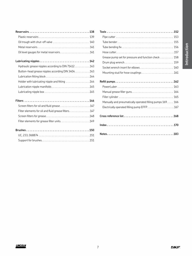
Reservoirs 138
Plastic reservoirs 139
Oil trough with shut-off valve 140
Metal reservoirs 141
Oil level gauges for metal reservoirs 141
Lubricating nipples 142
Hydraulic grease nipples according to DIN 71412 143
Button-head grease nipples according DIN 3404 143
Lubrication fitting block 144
Holder with lubricating nipple and fitting 144
Lubrication nipple manifolds 145
Lubricating nipple box 145
Filters 146
Screen filters for oil and fluid grease 147
Filter elements for oil and fluid grease filters 147
Screen filters for grease 148
Filter elements for grease filter units 149
Brushes 150
UC, 233, 068874 151
Support for brushes 151
Tools 152
Pipe cutter 153
Tube bender 155
Tube bending fix 156
Hose cutter 157
Grease pump set for pressure and function check 158
Drum plug wrench 159
Socket wrench insert for elbows 160
Mounting stud for hose couplings 161
Refill pumps 162
PowerLuber 163
Manual grease filler guns 164
Filler cylinder 165
Manually and pneumatically operated filling pumps 169 166
Electrically operated filling pump EFFP 167
Cross reference list 168
Index 170
Notes 183
Intr
oduct
ion
7

One global leader
Intr
oduct
ion
Two leading brands
SKF and Lincoln have joined forces to provide you with the world’s
most complete portfolio of innovative lubrication solutions – from
manual lubricators and tools, to the most advanced centralized and
automatic lubrication systems available
In addition to traditional lubrication products and systems,
we offer customized solutions for many industries such as pulp
and paper, steel, mining, agriculture, marine, rail, wind, construction,
machine tool and automotive SKF engineering and technical spe-
cialists partner with OEMs and end-users to develop system solu-
tions based on customer requirements We also offer a variety of
control and monitoring equipment for ease of use and to help
ensure proper lubrication
Both SKF and Lincoln systems are available through our global net-
work of lubrication experts, offering you world-class installation and
ongoing support on a local level – today and into the future With the
power of this network, and more than 200 years of combined friction
management experience, we can help you improve machine reliabil-
ity, reduce maintenance, increase productivity, enhance safety and
optimise manpower resources
8
Intr
oduct
ion
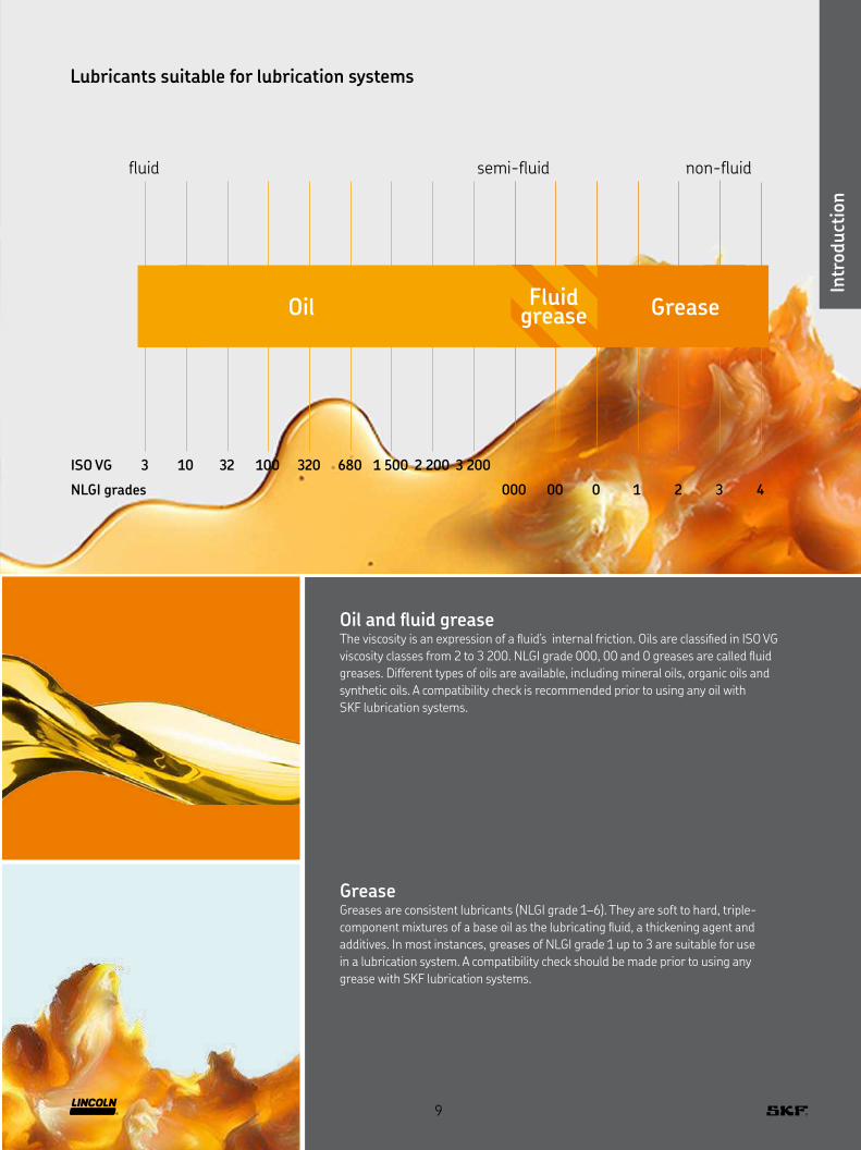
ISO VG 3 10 32 100 320 680 1 500 2 200 3 200
N LGI grades 000 00 0 1 2 3 4
fluid semi-fluid non-fluid
Oil Fluid grease Grease
Lubricants suitable for lubrication systems
Oil and fluid greaseThe viscosity is an expression of a fluid’s internal friction Oils are classified in ISO VG
viscosity classes from 2 to 3 200 NLGI grade 000, 00 and 0 greases are called fluid
greases Different types of oils are available, including mineral oils, organic oils and
synthetic oils A compatibility check is recommended prior to using any oil with
SKF lubrication systems
GreaseGreases are consistent lubricants (NLGI grade 1–6) They are soft to hard, triple-
component mixtures of a base oil as the lubricating fluid, a thickening agent and
additives In most instances, greases of NLGI grade 1 up to 3 are suitable for use
in a lubrication system A compatibility check should be made prior to using any
grease with SKF lubrication systems
9

Taper
ed s
leev
e unio
ns
Taper
ed s
leev
e unio
ns
Tapered sleeve fittings acc to DIN 3854/DIN 3862
Low-pressure fittings for max. 45 bar
Description
Solderless pipe unions for metal and plastic pipes are designed for
low pressure oil, fluid grease and grease lubrication systems with
pressures up to 45 bar and an operating temperature range from
-25 to 80 °C Depending on the selection of metering pipe material,
there are two different types of tapered sleeve fittings with different
components available: Tapered sleeve fittings for plastic pipes and
double-cone sleeve fittings for metal pipes For both types of unions,
a counterbore acc to DIN 3862 is necessary
Features and benefits
• Cost-efficient connection solution for low-pressure systems
• Suitable for oil, fluid grease and grease
• Simple and user-friendly assembly
• Virtually leakage-free union
10

Taper
ed s
leev
e unio
ns
Applications
• Paper and packaging industry
• Food and beverage industry
• Assembly and automation
• Part assembly lines
• Injection molding
• Mobile on-road
• Machine tools
• Etc
11
Taper
ed s
leev
e unio
ns
Taper
ed s
leev
e fitt
ings
Keg
elri
ngve
rsch
raubungen
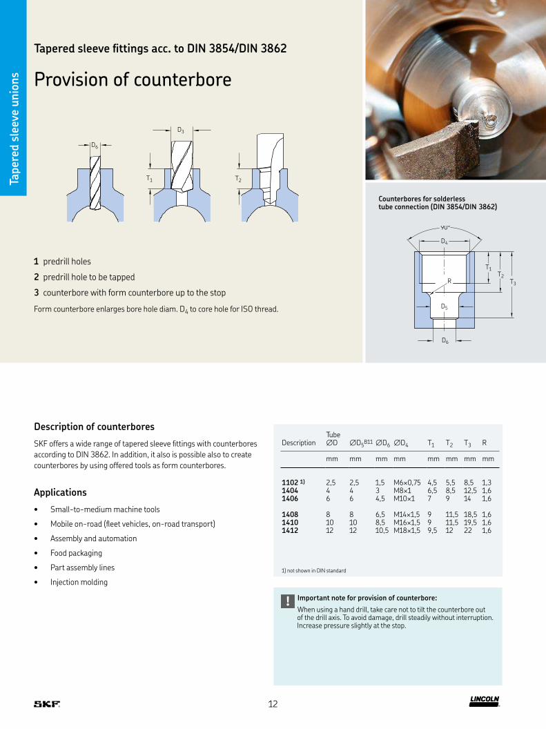
Counterbores for solderless tube connection (DIN 3854/DIN 3862)
Important note for provision of counterbore:
When using a hand drill, take care not to tilt the counterbore out of the drill axis To avoid damage, drill steadily without interruption Increase pressure slightly at the stop
!
D3
T2T1
D6
1 predrill holes
2 predrill hole to be tapped
3 counterbore with form counterbore up to the stop
Form counterbore enlarges bore hole diam D4 to core hole for ISO thread
T1T2
T3
D4
90°
D5
D6
R
Description of counterbores
SKF offers a wide range of tapered sleeve fittings with counterbores
according to DIN 3862 In addition, it also is possible also to create
counterbores by using offered tools as form counterbores
Applications
• Small-to-medium machine tools
• Mobile on-road (fleet vehicles, on-road transport)
• Assembly and automation
• Food packaging
• Part assembly lines
• Injection molding
DescriptionTube ∅D ∅D5
B11 ∅D6 ∅D4 T1 T2 T3 R
mm mm mm mm mm mm mm mm
1102 1) 2,5 2,5 1,5 M6×0,75 4,5 5,5 8,5 1,31404 4 4 3 M8×1 6,5 8,5 12,5 1,61406 6 6 4,5 M10×1 7 9 14 1,6
1408 8 8 6,5 M14×1,5 9 11,5 18,5 1,61410 10 10 8,5 M16×1,5 9 11,5 19,5 1,61412 12 12 10,5 M18×1,5 9,5 12 22 1,6
1) not shown in DIN standard
Taper
ed s
leev
e unio
ns
Tapered sleeve fittings acc to DIN 3854/DIN 3862
Provision of counterbore
12

Taper
ed s
leev
e unio
ns
Description
Solderless pipe unions for metal pipes consist of a socket union,
a double-cone sleeve and a fitting with counterbore according
to DIN 2862
Initial assembly
Cut the metal pipe straight to length using a suitable tool, e g ,
a pipe cutter Push the socket union and the double-cone sleeve
onto the end of the metal pipe Insert the end of the metal pipe
into the depression until the stop and tighten the socket
union finger-tight Then tighten the socket union again
by a maximum of 1 1/2 revolutions
Repeat assembly
After each time the screw union is loosened, the socket union
must be firmly retightened (with the same force) as in the
initial assembly
Description
Solderless pipe unions for plastic pipes consist of a socket union, a
tapered sleeve, a reinforcing socket and a fitting with counterbore
according to DIN 2862
Initial assembly
Cut the plastic pipe straight to length using a suitable tool, e g , a
hose cutter Insert the reinforcing socket into the end of the plastic
pipe to stabilize the end of the pipe being assembled This prevents
the plastic pipe from being constricted during assembly Push the
socket union and the tapered sleeve onto the end of the plastic pipe
Insert the end of the plastic pipe into the depression until the stop
and tighten the socket union finger-tight Then tighten the socket
union again by a maximum of 1 1/2 revolutions
Repeat assembly
Each time after the screw union is loosened, the socket union must be
firmly retightened (with the same force) as in the initial assembly
Solderless pipe unions for metal pipes Solderless pipe unions for plastic pipes
Double-tapered sleeve
Socket union
Tapered sleeve
Reinforcing socket
Socket union
Taper
ed s
leev
e unio
nsUnions for plastic pipes
Tapered sleeve fittings
Unions for metal pipes
13
Taper
ed s
leev
e unio
ns
D
Solderless pipe union with tapered sleeve
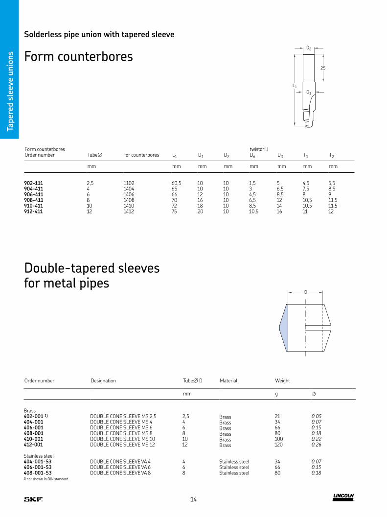
Form counterbores
Order number Designation Tube∅ D Material Weight
mm g lb
Brass402-001 1) DOUBLE CONE SLEEVE MS 2,5 2,5 Brass 21 0.05404-001 DOUBLE CONE SLEEVE MS 4 4 Brass 34 0.07406-001 DOUBLE CONE SLEEVE MS 6 6 Brass 66 0.15408-001 DOUBLE CONE SLEEVE MS 8 8 Brass 80 0.18410-001 DOUBLE CONE SLEEVE MS 10 10 Brass 100 0.22412-001 DOUBLE CONE SLEEVE MS 12 12 Brass 120 0.26
Stainless steel404-001-S3 DOUBLE CONE SLEEVE VA 4 4 Stainless steel 34 0.07406-001-S3 DOUBLE CONE SLEEVE VA 6 6 Stainless steel 66 0.15408-001-S3 DOUBLE CONE SLEEVE VA 8 8 Stainless steel 80 0.181) not shown in DIN standard
L1
25
D1
D2
Form counterbores Order number Tube∅ for counterbores L1 D1 D2
twistdrill D6 D3 T1 T2
mm mm mm mm mm mm mm mm
902-111 2,5 1102 60,5 10 10 1,5 5 4,5 5,5904-411 4 1404 65 10 10 3 6,5 7,5 8,5906-411 6 1406 66 12 10 4,5 8,5 8 9908-411 8 1408 70 16 10 6,5 12 10,5 11,5910-411 10 1410 72 18 10 8,5 14 10,5 11,5912-411 12 1412 75 20 10 10,5 16 11 12
Double-tapered sleeves for metal pipes
14

Taper
ed s
leev
e unio
ns
D1
L2
L1
Order number Designation Tube∅ D1 L1 L2 Material Weight (100 pcs)
mm mm mm mm mm g lb
Steel, galvanized402-002 SOCKET UNION ST 2,5 - M6×0,75 ZN-LL 2,5 M6×0,75 9 3 7 Steel, galvanized 166 0.37404-002 SOCKET UNION ST 4 - M8×1 ZN-LL 4 M8 ×1 12 4 8 Steel, galvanized 300 0.66406-002 SOCKET UNION ST 6 - M10×1 ZN-LL 6 M10 ×1 13 4 10 Steel, galvanized 400 0.88408-202 SOCKET UNION ST 8 - M14×1,5 ZN-L 8 M14 ×1,5 16 4,5 14 Steel, galvanized 1 000 2.21410-002 SOCKET UNION ST 10 - M16×1,5 ZN-L 10 M16 ×1,5 17 5,5 17 Steel, galvanized 1 400 3.09412-002 SOCKET UNION ST 12 - M18×1,5 ZN-L 12 M18 ×1,5 18 6 19 Steel, galvanized 1 800 3.97
Stainless steel404-002-S3 SOCKET UNION VA 4 - M8×1-L 4 M8 ×1 12 4 8 Stainless steel 300 0.66406-002-S3 SOCKET UNION VA 6 - M10×1-L 6 M10 ×1 13 4 10 Stainless steel 400 0.88408-202-S3 SOCKET UNION VA 8 - M14×1,5-L 8 M14 ×1,5 16 4,5 14 Stainless steel 1 000 2.21
Solderless pipe union with tapered sleeve
Socket unions for metal pipes acc. to DIN 3871
Reinforcing sockets for plastic tubes
L
D2
D1
Order number Designation Tube∅ D1 D2 L Material Weight
mm mm mm mm g lb
402-603 REINFORCING SLEEVE MS F, TUBE 2,5×0,5 2,5× 0,5 1,4 2,3 8 Brass 5 0.01404-603 REINFORCING SLEEVE MS F, TUBE 4×0,85 4× 0,85 2,2 3,8 10 Brass 8 0.02406-603 REINFORCING SLEEVE MS F, TUBE 6×1 6× 1 3,9 5,8 12 Brass 12 0.03406-613 REINFORCING SLEEVE MS F, TUBE 6×1,25 6× 1,25 3,4 5,8 12 Brass 15 0.03408-603 REINFORCING SLEEVE MS F, TUBE 8×1,25 8× 1,25 5,4 7,8 15 Brass 20 0.04410-603 REINFORCING SLEEVE MS F, TUBE 10×1,5 10× 1,5 6,9 9,8 18 Brass 24 0.05412-603 REINFORCING SLEEVE MS F, TUBE 12×1,5 12× 1,5 8,9 11,8 20 Brass 26 0.06
15

Taper
ed s
leev
e unio
ns
Solderless pipe union with tapered sleeve
Tapered sleeves for plastic tubes acc. to DIN 3862
Order number Designation Tube∅ D Material Weight (100 pcs)
mm g lb
402-611 CONE SLEEVE MS 2,5 2,5 Brass 100 0.22404-611 CONE SLEEVE MS 4 4 Brass 120 0.26406-611 CONE SLEEVE MS 6 6 Brass 160 0.35408-611 CONE SLEEVE MS 8 8 Brass 200 0.44410-611 CONE SLEEVE MS 10 10 Brass 250 0.55412-611 CONE SLEEVE MS 12 12 Brass 300 0.66
D
Socket unions for plastic tubes acc. to DIN 3871
D1
L2
L1
Order number Designation Tube∅ D1 L1 L2 Material Weight (100 pcs)
mm mm mm mm mm g lb
Steel, galvanized402-612 SOCKET UNION ST 2,5 - M6×0,75 ZN 2,5 M6 ×0,75 9 3 7 Steel, galvanized 100 0.22404-612 SOCKET UNION ST 4 - M8×1 ZN 4 M8×1 12 4 8 Steel, galvanized 200 0.44406-612 SOCKET UNION ST 6 - M10×1 ZN 6 M10 ×1 13 4 10 Steel, galvanized 300 0.66408-612 SOCKET UNION ST 8 - M14×1,5 ZN 8 M14 ×1,5 16 4,5 14 Steel, galvanized 900 1.98410-612 SOCKET UNION ST 10 - M16 ×1,5 ZN 10 M16×1,5 17 5,5 17 Steel, galvanized 1 300 2.87412-612 SOCKET UNION ST 12 - M18 ×1,5 ZN 12 M18 ×1,5 18 6 19 Steel, galvanized 1 700 3.75
Brass404-612-MS SOCKET UNION MS 4 - M8×1 4 M8 ×1 12 4 8 Brass 200 0.44406-612-MS SOCKET UNION MS 6 - M10×1 6 M10 ×1 13 4 10 Brass 300 0.66408-612-MS SOCKET UNION MS 8 - M14×1,5 8 M14×1,5 16 4,5 14 Brass 900 1.98410-612-MS SOCKET UNION MS 10 - M16×1,5 10 M16 ×1,5 17 5,5 17 Brass 1 300 2.87
16
Taper
ed s
leev
e unio
ns
Solderless pipe union with tapered sleeve
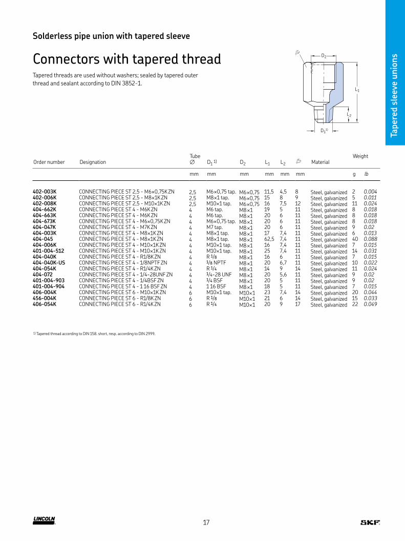
Connectors with tapered thread D2
D11)
L2
L1
Order number DesignationTube ∅ D1 1) D2 L1 L2 Material
Weight
mm mm mm mm mm mm g lb
402-003K CONNECTING PIECE ST 2,5 - M6×0,75K ZN 2,5 M6 ×0,75 tap M6 ×0,75 11,5 4,5 8 Steel, galvanized 2 0.004402-006K CONNECTING PIECE ST 2,5 - M8×1K ZN 2,5 M8 ×1 tap M6 ×0,75 15 8 9 Steel, galvanized 5 0.011402-008K CONNECTING PIECE ST 2,5 - M10×1K ZN 2,5 M10×1 tap M6 ×0,75 16 7,5 12 Steel, galvanized 11 0.024404-662K CONNECTING PIECE ST 4 - M6K ZN 4 M6 tap M8 ×1 19 5 11 Steel, galvanized 8 0.018404-663K CONNECTING PIECE ST 4 - M6K ZN 4 M6 tap M8 ×1 20 6 11 Steel, galvanized 8 0.018404-673K CONNECTING PIECE ST 4 - M6×0,75K ZN 4 M6×0,75 tap M8 ×1 20 6 11 Steel, galvanized 8 0.018404-047K CONNECTING PIECE ST 4 - M7K ZN 4 M7 tap M8 ×1 20 6 11 Steel, galvanized 9 0.02404-003K CONNECTING PIECE ST 4 - M8×1K ZN 4 M8×1 tap M8 ×1 17 7,4 11 Steel, galvanized 6 0.013404-045 CONNECTING PIECE ST 4 - M8×1K ZN 4 M8×1 tap M8 ×1 62,5 7,4 11 Steel, galvanized 40 0.088404-006K CONNECTING PIECE ST 4 - M10×1K ZN 4 M10×1 tap M8 ×1 16 7,4 11 Steel, galvanized 7 0.015401-004-512 CONNECTING PIECE ST 4 - M10×1K ZN 4 M10×1 tap M8 ×1 25 7,4 11 Steel, galvanized 14 0.031404-040K CONNECTING PIECE ST 4 - R1/8K ZN 4 R 1/8 M8 ×1 16 6 11 Steel, galvanized 7 0.015404-040K-US CONNECTING PIECE ST 4 - 1/8NPTF ZN 4 1/8 NPTF M8 ×1 20 6,7 11 Steel, galvanized 10 0.022404-054K CONNECTING PIECE ST 4 - R1/4K ZN 4 R 1/4 M8 ×1 14 9 14 Steel, galvanized 11 0.024404-072 CONNECTING PIECE ST 4 - 1/4-28UNF ZN 4 1/4-28 UNF M8 ×1 20 5,6 11 Steel, galvanized 9 0.02401-004-903 CONNECTING PIECE ST 4 - 1/4BSF ZN 4 1/4 BSF M8 ×1 20 5 11 Steel, galvanized 9 0.02401-004-904 CONNECTING PIECE ST 4 - 1 16 BSF ZN 4 1 16 BSF M8 ×1 18 5 11 Steel, galvanized 7 0.015406-004K CONNECTING PIECE ST 6 - M10×1K ZN 6 M10×1 tap M10× 1 23 7,4 14 Steel, galvanized 20 0.044456-004K CONNECTING PIECE ST 6 - R1/8K ZN 6 R 1/8 M10× 1 21 6 14 Steel, galvanized 15 0.033406-054K CONNECTING PIECE ST 6 - R1/4K ZN 6 R 1/4 M10× 1 20 9 17 Steel, galvanized 22 0.049
1) Tapered thread according to DIN 158 short, resp according to DIN 2999
Tapered threads are used without washers; sealed by tapered outer
thread and sealant according to DIN 3852-1
17

Taper
ed s
leev
e unio
ns
Solderless pipe union with tapered sleeve
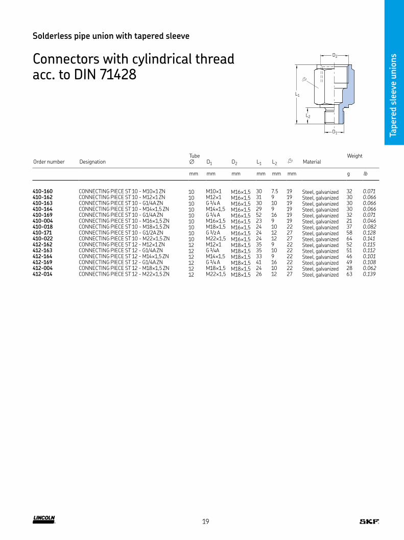
Connectors with cylindrical thread acc. to DIN 71428
L1
L2
D2
D1
Order number DesignationTube ∅ D1 D2 L1 L2 Material
Weight
mm mm mm mm mm mm g lb
402-004 CONNECTING PIECE ST 2,5 - M6 ZN 2,5 M6 M6×0,75 13 5,5 9 Steel, galvanized 3 0.007402-003 CONNECTING PIECE ST 2,5 - M6×0,75 ZN 2,5 M6×0,75 M6×0,75 13 5,5 9 Steel, galvanized 3 0.007402-006 CONNECTING PIECE ST 2,5 - M8×1 ZN 2,5 M8×1 M6×0,75 15 7,5 11 Steel, galvanized 7 0.015404-004 CONNECTING PIECE ST 4 - M8×1 ZN 4 M8×1 M8×1 24 14 11 Steel, galvanized 9 0.02404-005 CONNECTING PIECE ST 4 - M8×1 ZN 4 M8×1 M8×1 32 22 11 Steel, galvanized 14 0.031404-061 CONNECTING PIECE ST 4 - M5 ZN 4 M5 M8×1 20 5,5 11 Steel, galvanized 9 0.02404-063 CONNECTING PIECE ST 4 - M8 ZN 4 M8 M8×1 22 8 11 Steel, galvanized 10 0.022404-003 CONNECTING PIECE ST 4 - M8×1 ZN 4 M8×1 M8×1 18 7,5 11 Steel, galvanized 6 0.013404-006 CONNECTING PIECE ST 4 - M10×1 ZN 4 M10×1 M8×1 18 7,5 14 Steel, galvanized 13 0.029404-040 CONNECTING PIECE ST 4 - G1/8A ZN 4 G 1/8 A M8×1 18 8 14 Steel, galvanized 13 0.029404-162 CONNECTING PIECE ST 4 - M12×1 ZN 4 M12×1 M8×1 18 9 17 Steel, galvanized 19 0.042404-164 CONNECTING PIECE ST 4 - M14×1,5 ZN 4 M14×1,5 M8×1 18 9 17 Steel, galvanized 21 0.046301-005-S3 CONNECTING PIECE VA 6 - M14×1,5 6 M14×1,5 M10×1 18 9 17 Stainless steel 19 0.042406-004-S3 CONNECTING PIECE VA 6 - M10×1 6 M10×1 M10×1 18 7,5 14 Stainless steel 10 0.022406-158-S3 CONNECTING PIECE VA 6 - M8×1 6 M8×1 M10×1 23 7,5 14 Stainless steel 15 0.033267-001 17 CONNECTING PIECE MS 6 - G1/8A 6 G 1/8 A M10×1 24 8 14 Brass 18 0.04406-163 CONNECTING PIECE MS 6 - M12×1 6 M12×1 M10×1 19 9 17 Brass 20 0.044D301-005-MS CONNECTING PIECE MS 6 - M14×1,5 6 M14×1,5 M10×1 20 9 17 Brass 24 0.053406-167 CONNECTING PIECE MS 6 - M16×1,5 6 M16×1,5 M10×1 19 9 19 Brass 31 0.068267-001 19 CONNECTING PIECE MS 6 - M18×1,5 6 M18×1,5 M10×1 21 10 22 Brass 71 0.157406-158 CONNECTING PIECE ST 6 - M8×1 ZN 6 M8×1 M10×1 23 7,5 14 Steel, galvanized 38 0.084406-004 CONNECTING PIECE 6 - M10×1 ZN 6 M10×1 M10×1 18 7,5 14 Steel, galvanized 10 0.022406-162 CONNECTING PIECE ST 6 - M12×1 ZN 6 M12×1 M10×1 19 9 17 Steel, galvanized 18 0.04406-054 CONNECTING PIECE ST 6 - G1/4A ZN 6 G 1/4 A M10×1 20 10 17 Steel, galvanized 20 0.044301-005 CONNECTING PIECE ST 6 - M14×1,5 ZN 6 M14×1,5 M10×1 18 9 17 Steel, galvanized 18 0.04406-166 CONNECTING PIECE ST 6 - M16×1,5 ZN 6 M16×1,5 M10×1 19 9 19 Steel, galvanized 28 0.062406-055 CONNECTING PIECE ST 6 - G3/8A ZN 6 G 3/8 A M10×1 21 10 22 Steel, galvanized 41 0.09D408-004-MS CONNECTING PIECE MS 8 - M10×1 8 M10×1 M14×1,5 29 7,5 17 Brass 29 0.064D301-001-MS CONNECTING PIECE MS 8 - M14×1,5 8 M14×1,5 M14×1,5 28 9 17 Brass 29 0.064D301-020-MS CONNECTING PIECE MS 8 - G1/4A 8 G 1/4 A M14×1,5 30 10 17 Brass 30 0.066267-001 13 CONNECTING PIECE MS 8 - G1/8A 8 G 1/8 A M14×1,5 24 12 27 Brass 71 0.157301-020-S3 CONNECTING PIECE VA 8 - G1/4A 8 G 1/4 A M14×1,5 23 10 17 Stainless steel 17 0.037408-004 CONNECTING PIECE ST 8 - M10×1 ZN 8 M10×1 M14×1,5 28 7,5 17 Steel, galvanized 25 0.055408-154 CONNECTING PIECE ST 8 - G1/8A ZN 8 G 1/8A M14×1,5 29 8 17 Steel, galvanized 26 0.057408-160 CONNECTING PIECE ST 8 - G1/4A ZN 8 G 1/4 A M14×1,5 30 16 17 Steel, galvanized 22 0.049408-162 CONNECTING PIECE ST 8 - M12×1 ZN 8 M12×1 M14×1,5 29 9 17 Steel, galvanized 26 0.057301-020 CONNECTING PIECE ST 8 - G1/4A ZN 8 G 1/4 A M14×1,5 23 10 17 Steel, galvanized 16 0.035301-001 CONNECTING PIECE ST 8 - M14×1,5 ZN 8 M14×1,5 M14×1,5 26 9 17 Steel, galvanized 23 0.051408-005 CONNECTING PIECE ST 8 - M16×1,5 ZN 8 M16×1,5 M14×1,5 22 9 19 Steel, galvanized 30 0.066408-006 CONNECTING PIECE ST 8 - M18×1,5 ZN 8 M18×1,5 M14×1,5 22 10 22 Steel, galvanized 40 0.088408-022 CONNECTING PIECE ST 8 - M22×1,5 ZN 8 M22×1,5 M14×1,5 24 12 27 Steel, galvanized 71 0.157
18
Taper
ed s
leev
e unio
ns
Solderless pipe union with tapered sleeve
Connectors with cylindrical thread acc. to DIN 71428
Order number DesignationTube ∅ D1 D2 L1 L2 Material
Weight
mm mm mm mm mm mm g lb
410-160 CONNECTING PIECE ST 10 - M10×1 ZN 10 M10×1 M16×1,5 30 7 5 19 Steel, galvanized 32 0.071410-162 CONNECTING PIECE ST 10 - M12×1 ZN 10 M12×1 M16×1,5 31 9 19 Steel, galvanized 30 0.066410-163 CONNECTING PIECE ST 10 - G1/4A ZN 10 G 1/4 A M16×1,5 30 10 19 Steel, galvanized 30 0.066410-164 CONNECTING PIECE ST 10 - M14×1,5 ZN 10 M14×1,5 M16×1,5 29 9 19 Steel, galvanized 30 0.066410-169 CONNECTING PIECE ST 10 - G1/4A ZN 10 G 1/4 A M16×1,5 52 16 19 Steel, galvanized 32 0.071410-004 CONNECTING PIECE ST 10 - M16×1,5 ZN 10 M16×1,5 M16×1,5 23 9 19 Steel, galvanized 21 0.046410-018 CONNECTING PIECE ST 10 - M18×1,5 ZN 10 M18×1,5 M16×1,5 24 10 22 Steel, galvanized 37 0.082410-171 CONNECTING PIECE ST 10 - G1/2A ZN 10 G 1/2 A M16×1,5 24 12 27 Steel, galvanized 58 0.128410-022 CONNECTING PIECE ST 10 - M22×1,5 ZN 10 M22×1,5 M16×1,5 24 12 27 Steel, galvanized 64 0.141412-162 CONNECTING PIECE ST 12 - M12×1 ZN 12 M12×1 M18×1,5 35 9 22 Steel, galvanized 52 0.115412-163 CONNECTING PIECE ST 12 - G1/4A ZN 12 G 1/4A M18×1,5 35 10 22 Steel, galvanized 51 0.112412-164 CONNECTING PIECE ST 12 - M14×1,5 ZN 12 M14×1,5 M18×1,5 33 9 22 Steel, galvanized 46 0.101412-169 CONNECTING PIECE ST 12 - G1/4A ZN 12 G 1/4 A M18×1,5 41 16 22 Steel, galvanized 49 0.108412-004 CONNECTING PIECE ST 12 - M18×1,5 ZN 12 M18×1,5 M18×1,5 24 10 22 Steel, galvanized 28 0.062412-014 CONNECTING PIECE ST 12 - M22×1,5 ZN 12 M22×1,5 M18×1,5 26 12 27 Steel, galvanized 63 0.139
L1
L2
D2
D1
19

Taper
ed s
leev
e unio
ns
Solderless pipe union with tapered sleeve
Bracketed connectors
Order number Designation Tube∅ Material Weight
mm g lb
Die-cast zinc504-004 TUBE FITTING ZN G4 + BRACKET 4 Die-cast zinc 26 0.06
Brass506-010 TUBE FITTING MS G6 + BRACKET 6 Brass 30 0.07
6
7
20
14
33
∅12
6.4
M8×1
30
14
5
6.4
13
27
∅14 M10×1
30
40
D1
6.6
5
L
B
H
25
9 6.6
D1
5
19
20
30
43
D2
504-004 506-010
DAR506, DAR508 DAR510, DAR510-S1
Order number DesignationTube ∅ D1 D2 B H L1 Material Weight
mm mm mm mm mm mm g lb
AluminumDAR506 TUBE FITTING AL G6 + BRACKET - M10×1 6 M10×1 – 15 20 12 Aluminum 26 0.06DAR508 TUBE FITTING AL G8 + BRACKET - M14×1,5 8 M14×1,5 – 20 25 15 Aluminum 41 0.09
Steel, galvanizedDAR510 TUBE FITTING ST G10 + BRACKET - M16×1,5 ZN 10 M16×1,5 M16×1,5 – – – Steel, galvanized 140 0.31DAR510-S1 TUBE FITTING ST G8/10 + BRACKET - M14×1,5 ZN 8 / 10 M14×1,5 M16×1,5 – – – Steel, galvanized 150 0.33
20
Taper
ed s
leev
e unio
ns
Solderless pipe union with tapered sleeve
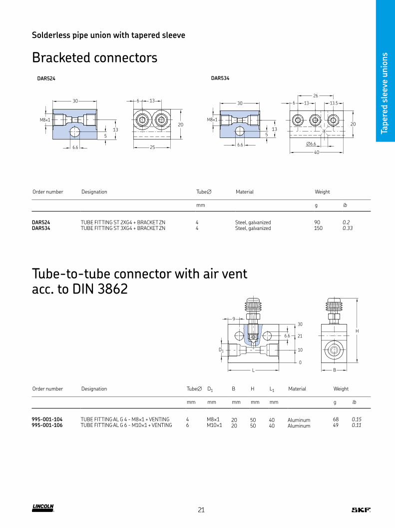
Bracketed connectors
30
M8×1
6 13
6.6 25
5
13
20
30
M8×1
6 13
26
13.5
6.6
40
∅6.6
5
13
20
DAR524 DAR534
Order number Designation Tube∅ Material Weight
mm g lb
DAR524 TUBE FITTING ST 2XG4 + BRACKET ZN 4 Steel, galvanized 90 0.2DAR534 TUBE FITTING ST 3XG4 + BRACKET ZN 4 Steel, galvanized 150 0.33
Tube-to-tube connector with air vent acc. to DIN 3862
30
10
0
216.6
L
D1
9
H
B
Order number Designation Tube∅ D1 B H L1 Material Weight
mm mm mm mm mm g lb
995-001-104 TUBE FITTING AL G 4 - M8×1 + VENTING 4 M8×1 20 50 40 Aluminum 68 0.15995-001-106 TUBE FITTING AL G 6 - M10×1 + VENTING 6 M10×1 20 50 40 Aluminum 49 0.11
21

Taper
ed s
leev
e unio
ns
Solderless pipe union with tapered sleeve
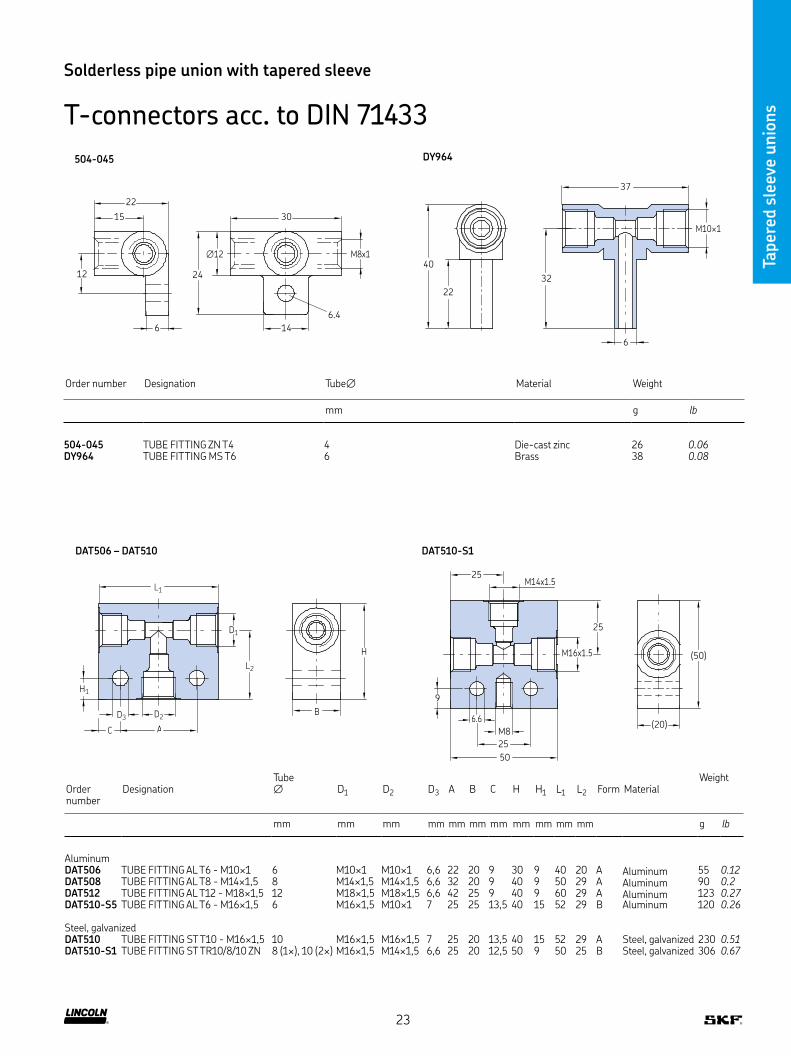
T-connectors acc. to DIN 71433
Order number Designation Tube∅ D1 D2 D3 L1 L2 Form Material Weight
mm mm mm mm mm mm g lb
504-008 TUBE FITTING ZN T4 - M8×1 4 M8×1 M8×1 12 15 30,5 A Die-cast zinc 20 0.04506-008 TUBE FITTING ZN T6 - M10×1 6 M10×1 M10×1 14 18 36 A Die-cast zinc 31 0.07510-102 TUBE FITTING ZN T10 - M16×1,5 10 M16×1,5 M16×1,5 20 25 50 A Die-cast zinc 62 0.14506-408 TUBE FITTING ZN TR6/4 - M10×1 6 / 4 M10×1 M8×1 14 18 36 B Die-cast zinc 33 0.07
L2
D1
L1
D3
D2
D3
∅18
D2
37
8.5
23
20
∅18
6.6
46
M14x1.5
Order number Designation Tube∅ D2 Form Material Weight
mm mm g lb
508-602-2 TUBE FITTING ZN TR8/6 8 / 6 M10×1 B Die-cast zinc 58 0.13508-002-2 TUBE FITTING ZN TR8 8 M14×1,5 A Die-cast zinc 50 0.11
22
Taper
ed s
leev
e unio
ns
Solderless pipe union with tapered sleeve
T-connectors acc. to DIN 71433
24
∅12
30
14
M8x1
6.4
12
6
15
22
40
22
32
6
37
M10×1
D2D3
C A
D1
L2
L1
H1
B
H
6.6
M8
25
50
M16x1.5
(20)
25
M14x1.525
9
(50)
504-045 DY964
DAT506 – DAT510 DAT510-S1
Order number Designation Tube∅ Material Weight
mm g lb
504-045 TUBE FITTING ZN T4 4 Die-cast zinc 26 0.06DY964 TUBE FITTING MS T6 6 Brass 38 0.08
Order number
DesignationTube ∅ D1 D2 D3 A B C H H1 L1 L2 Form Material
Weight
mm mm mm mm mm mm mm mm mm mm mm g lb
AluminumDAT506 TUBE FITTING AL T6 - M10×1 6 M10×1 M10×1 6,6 22 20 9 30 9 40 20 A Aluminum 55 0.12DAT508 TUBE FITTING AL T8 - M14×1,5 8 M14×1,5 M14×1,5 6,6 32 20 9 40 9 50 29 A Aluminum 90 0.2DAT512 TUBE FITTING AL T12 - M18×1,5 12 M18×1,5 M18×1,5 6,6 42 25 9 40 9 60 29 A Aluminum 123 0.27DAT510-S5 TUBE FITTING AL T6 - M16×1,5 6 M16×1,5 M10×1 7 25 25 13,5 40 15 52 29 B Aluminum 120 0.26
Steel, galvanizedDAT510 TUBE FITTING ST T10 - M16×1,5 10 M16×1,5 M16×1,5 7 25 20 13,5 40 15 52 29 A Steel, galvanized 230 0.51DAT510-S1 TUBE FITTING ST TR10/8/10 ZN 8 (1×), 10 (2×) M16×1,5 M14×1,5 6,6 25 20 12,5 50 9 50 25 B Steel, galvanized 306 0.67
23

Taper
ed s
leev
e unio
ns
Solderless pipe union with tapered sleeve
Bulkhead connectors with tapered thread D2
D1
L2
L1
Order number DesignationTube ∅ D1
1) D2 L1 L2 MaterialWeight
mm mm mm mm mm mm g lb
404-003DK BULKHEAD CONNECTORS ST 4 - M8×1 ZN 4 M8×1 tap M8×1 17 7,4 11 Steel, galvanized 6 0.013404-006DK BULKHEAD CONNECTORS ST 4 - M10×1 ZN 4 M10×1 tap M8×1 16 7,4 11 Steel, galvanized 7 0.015406-004DK BULKHEAD CONNECTORS ST 6 - M10×1 ZN 6 M10×1 tap M10×1 18 7,4 14 Steel, galvanized 10 0.022301-001DK BULKHEAD CONNECTORS ST 8 - M14×1,5 ZN 8 M14×1,5 tap M14×1,5 24 11 17 Steel, galvanized 19 0.042410-004DK BULKHEAD CONNECTORS ST 10 - M16×1,5 ZN 10 M16×1,5 tap M16×1,5 24 11 19 Steel, galvanized 22 0.049
1) Tapered thread according to DIN 158 tap short
Tube-to-tube connectors
Order number DesignationTube ∅ D2 D3 ∅D4 L1 L2 Material
Weight
mm mm mm mm mm mm mm g lb
404-010 TUBE FITTING ST G 4 ZN 4 M8×1 M8×1 10,8 27 13 11 Steel, galvanized 14 0.03406-010 TUBE FITTING ST G 6 ZN 6 M10×1 M10×1 13,8 30 10 14 Steel, galvanized 25 0.06406-805 TUBE FITTING ST GR 6/8 ZN 6 / 8 M14×1,5 M10×1 16,8 35 11 17 Steel, galvanized 43 0.09408-010 TUBE FITTING ST G 8 ZN 8 M14×1,5 M14×1,5 16,8 40 14 17 Steel, galvanized 40 0.09410-010 TUBE FITTING ST G 10 ZN 10 M16×1,5 M16×1,5 18,8 42 13 19 Steel, galvanized 54 0.12412-010 TUBE FITTING ST G 12 ZN 12 M18×1,5 M18×1,5 21,8 48 18 22 Steel, galvanized 85 0.19
L1
L2
D2 D3∅D4
24

Taper
ed s
leev
e unio
ns
Solderless pipe union with tapered sleeve
Straight bulkhead fittings acc. to DIN 71429
D2 D3 D1
L2
L1
L1
D2 D1
Order number DesignationTube ∅ D1
1) D2 D3 L1 L2 MaterialWeight
mm mm mm mm mm mm mm g lb
404-008 TUBE FITTING ST SV 4 - M14×1,5 ZN 4 M14×1,5 M8×1 M8×1 27 19 17 Steel, galvanized 30 0.07404-009 TUBE FITTING ST SV 4 - M14×1,5 ZN 4 M14×1,5 M8×1 M8×1 38 30 17 Steel, galvanized 39 0.09406-008 TUBE FITTING ST SV 6 - M14×1,5 ZN 6 M14×1,5 M10×1 M10×1 30 20 17 Steel, galvanized 30 0.07406-005 TUBE FITTING ST SV 6/8 - M16×1,5 ZN 6 / 8 M16×1,5 M14×1,5 M10×1 35 23 19 Steel, galvanized 38 0.08408-008 TUBE FITTING ST SV 8 - M20×1,5 ZN 8 M20×1,5 M14×1,5 M14×1,5 40 28 24 Steel, galvanized 75 0.17410-008 TUBE FITTING ST SV 10 - M20×1,5 ZN 10 M20×1,5 M16×1,5 M16×1,5 42 27 24 Steel, galvanized 73 0.16412-008 TUBE FITTING ST SV 12 - M24×1,5 ZN 12 M24×1,5 M18×1,5 M18×1,5 48 33 27 Steel, galvanized 114 0.25
Order number DesignationTube ∅ D1 D2 L1 Material
Weight
mm mm mm mm mm g lb
44-1755-2019 REDUCING PIECE ST 4 - G1/4I X M10×1I SW24 ZN 4 G 1/4 M10×1 33 24 Steel, galvanized 100 0.22
Reducing piece
25
Taper
ed s
leev
e unio
ns
Solderless pipe union with tapered sleeve
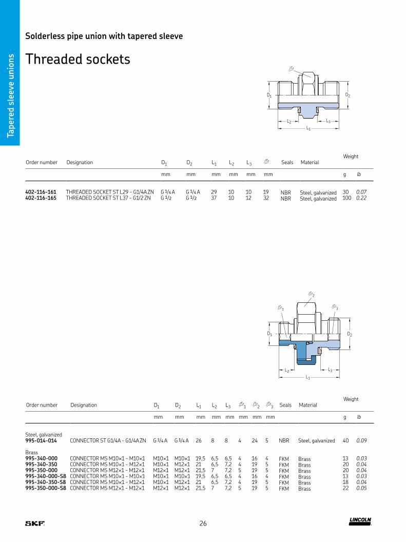
Threaded sockets
L1
L2 L3
D2D1
Order number Designation D1 D2 L1 L2 L3 Seals MaterialWeight
mm mm mm mm mm mm g lb
402-116-161 THREADED SOCKET ST L29 - G1/4A ZN G 1/4 A G 1/4 A 29 10 10 19 NBR Steel, galvanized 30 0.07402-116-165 THREADED SOCKET ST L37 - G1/2 ZN G 1/2 G 1/2 37 10 12 32 NBR Steel, galvanized 100 0.22
Order number Designation D1 D2 L1 L2 L3 1 2 3 Seals MaterialWeight
mm mm mm mm mm mm mm mm g lb
Steel, galvanized995-014-014 CONNECTOR ST G1/4A - G1/4A ZN G 1/4 A G 1/4 A 26 8 8 4 24 5 NBR Steel, galvanized 40 0.09
Brass995-340-000 CONNECTOR MS M10×1 - M10×1 M10×1 M10×1 19,5 6,5 6,5 4 16 4 FKM Brass 13 0.03995-340-350 CONNECTOR MS M10×1 - M12×1 M10×1 M12×1 21 6,5 7,2 4 19 5 FKM Brass 20 0.04995-350-000 CONNECTOR MS M12×1 - M12×1 M12×1 M12×1 21,5 7 7,2 5 19 5 FKM Brass 20 0.04995-340-000-S8 CONNECTOR MS M10×1 - M10×1 M10×1 M10×1 19,5 6,5 6,5 4 16 4 FKM Brass 13 0.03995-340-350-S8 CONNECTOR MS M10×1 - M12×1 M10×1 M12×1 21 6,5 7,2 4 19 5 FKM Brass 18 0.04995-350-000-S8 CONNECTOR MS M12×1 - M12×1 M12×1 M12×1 21,5 7 7,2 5 19 5 FKM Brass 22 0.05
L1
L2 L3
D2D1
2
3 1
26

Taper
ed s
leev
e unio
ns
Solderless pipe union with tapered sleeve
Threaded sockets
L1
D1
L1
L2 L2
D1 D3 D2
Order number Designation D1 L1 MaterialWeight
mm mm mm g lb
Steel404-203 THREADED SOCKET ST L13 - M8×1 M8×1 13 3,5 Steel 3 0.007406-203 THREADED SOCKET ST L15 - M10×1 M10×1 15 3,5 Steel 6 0.013406-243-B 1) THREADED SOCKET ST L18 - M10×1 M10×1 18 3,5 Steel 7 0.015408-243-B 1) THREADED SOCKET ST L19 - M12×1 M12×1 19 5,5 Steel 9 0.02458-012 THREADED SOCKET ST L17 - M12×1 M12×1 17 5,5 Steel 8 0.018458-012-B 1) THREADED SOCKET ST L17 - M12×1 M12×1 17 5,5 Steel 8 0.018408-023 THREADED SOCKET ST L18 - M14×1,5 M14×1,5 18 5,5 Steel 13 0.029410-003 THREADED SOCKET ST L19 - M16×1,5 M16×1,5 19 7 Steel 16 0.035410-003-B 1) THREADED SOCKET ST L19 - M16×1,5 M16×1,5 19 7 Steel 17 0.037
Stainless steel408-033-S3 THREADED SOCKET VA L15 - G1/4A G 1/4 A 15 5,5 Stainless steel 9 0.02
1) Coated with microencapsulated adhesive
Order number Designation D1 D2 D3 L1 L2 MaterialWeight
mm mm mm mm mm mm g lb
Steel, galvanized406-103 THREADED SOCKET ST L20 - M10×1/M12×1 ZN M10×1 M12×1 5 20 6 14 Steel, galvanized 14 0.03408-103 THREADED SOCKET ST L21 - M12×1/M14×1,5 ZN M12×1 M14×1,5 6 21 7 17 Steel, galvanized 21 0.05853-750-024 THREADED SOCKET ST L31 - G1/4A/G1/4A ZN G 1/4 A G 1/4 A 7 31 10,5 19 Steel, galvanized 29 0.06
Brass406-233 THREADED SOCKET MS L26 - M10×1 M10×1 – 4 26 – – Brass 8 0.02
406-103, 408-103, 853-750-024
L1
D3 D1
406-233
27
Taper
ed s
leev
e unio
ns
Solderless pipe union with tapered sleeve
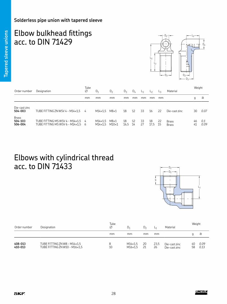
Elbow bulkhead fittings acc. to DIN 71429
D2D1
L2
L1
L3
D4
D2
D3
Order number DesignationTube ∅ D1 D2 D3 D4 L1 L2 L3 Material
Weight
mm mm mm mm mm mm mm mm g lb
Die-cast zinc504-003 TUBE FITTING ZN WSV 4 - M14×1,5 4 M14×1,5 M8×1 18 12 33 16 22 Die-cast zinc 30 0.07
Brass504-103 TUBE FITTING MS WSV 4 - M14×1,5 4 M14×1,5 M8×1 18 12 33 18 22 Brass 46 0.1506-004 TUBE FITTING MS WSV 6 - M14×1,5 6 M14×1,5 M10×1 16,5 14 27 17,5 15 Brass 41 0.09
Elbows with cylindrical thread acc. to DIN 71433
Order number DesignationTube ∅ D1 D2 L1 Material
Weight
mm mm mm mm g lb
408-013 TUBE FITTING ZN W8 - M14×1,5 8 M14×1,5 20 23,5 Die-cast zinc 40 0.09410-013 TUBE FITTING ZN W10 - M16×1,5 10 M16×1,5 21 26 Die-cast zinc 58 0.13
D1
D2
L1
9
28

Taper
ed s
leev
e unio
ns
Solderless pipe union with tapered sleeve
Elbows with tapered thread acc. to DIN 71429
L2
D2 D4
D1
D3
L3
L1
L2
D2 D4
D1
D3
L1
L3
Order number DesignationTube ∅ D1
1) D2 D3 D4 L1 L2 L3 MaterialWeight
mm mm mm mm mm mm mm mm mm g lb
504-510K ELBOW ZN 4 - M10×1K 4 M10×1 tap M8×1 13 13 21 16 10 14 Die-cast zinc 24 0.05514-018K ELBOW ZN 4 - R1/8 4 R 1/8 M8×1 13 13 21 16 10 14 Die-cast zinc 23 0.05506-508K ELBOW ZN 6 - M8×1K 6 M8×1 tap M10×1 12,5 14 18 18 10,5 14 Die-cast zinc 18 0.04506-510K ELBOW ZN 6 - M10×1K 6 M10×1 tap M10×1 12,5 14 18 18 10,5 14 Die-cast zinc 20 0.04506-512K ELBOW ZN 6 - M12×1K 6 M12×1 tap M10×1 12,5 14 18 18 10,5 14 Die-cast zinc 21 0.05508-512K ELBOW ZN 8 - M12×1K 8 M12×1 tap M14×1,5 14 19,5 19,5 24 10 14 Die-cast zinc 34 0.07
1) Tapered thread according to DIN 158 tap short, resp according to DIN 2999
Order number DesignationTube ∅ D1
1) D2 D3 D4 L1 L2 L3 MaterialWeight
mm mm mm mm mm mm mm mm g lb
Steel502-206K ELBOW ST 2 5 - M6K 2,5 M6 tap M6×0,75 – 8 10 9,5 6 Steel 6 0.01403-006-651 ELBOW ST 6 - R1/4K 6 R 1/4 M10×1 14 14 17 17,5 8,5 Steel 32 0.07
Brass506-202K ELBOW MS 6 - M10X1K 6 M10×1 tap M10×1 17 17 22 21 11 Brass 60 0.13
1) Tapered thread according to DIN 158 tap short, resp according to DIN 2999
29
Taper
ed s
leev
e unio
ns
Solderless pipe union with tapered sleeve
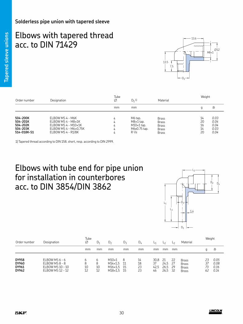
Elbows with tapered thread acc. to DIN 71429
13.6
13.5
7.5
D1
M8×1∅12
Order number DesignationTube ∅ D1
1) MaterialWeight
mm mm g lb
504-200K ELBOW MS 4 - M6K 4 M6 tap Brass 14 0.03504-201K ELBOW MS 4 - M8×1K 4 M8×1 tap Brass 20 0.04504-202K ELBOW MS 4 - M10×1K 4 M10×1 tap Brass 16 0.04504-203K ELBOW MS 4 - M6×0,75K 4 M6x0 75 tap Brass 14 0.03514-018K-S1 ELBOW MS 4 - R1/8K 4 R 1/8 Brass 20 0.04
1) Tapered thread according to DIN 158 short, resp according to DIN 2999
Elbows with tube end for pipe union for installation in counterbores acc. to DIN 3854/DIN 3862
Order number DesignationTube ∅ D1 D2 D3 D4 L1 L2 L2 Material
Weight
mm mm mm mm mm mm mm mm g lb
DY958 ELBOW MS 6 - 6 6 6 M10×1 8 14 30,8 21 22 Brass 23 0.05DY960 ELBOW MS 8 - 8 8 8 M14×1,5 11 18 37 24,5 27 Brass 37 0.08DY961 ELBOW MS 10 - 10 10 10 M16×1,5 15 23 42,5 26,5 29 Brass 73 0.16DY962 ELBOW MS 12 - 12 12 12 M18×1,5 15 23 46 26,5 32 Brass 62 0.14
D2 D4
L1
L3
D1
L2
1.4
D3
30
Taper
ed s
leev
e unio
ns
Solderless pipe union with tapered sleeve
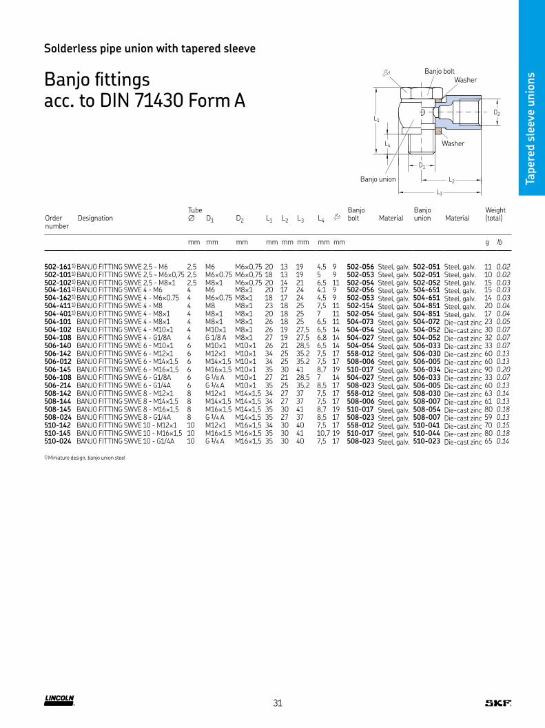
Banjo fittings acc. to DIN 71430 Form A
Order number
DesignationTube ∅ D1 D2 L1 L2 L3 L4
Banjo bolt Material
Banjo union Material
Weight (total)
mm mm mm mm mm mm mm mm g lb
502-161 1) BANJO FITTING SWVE 2,5 - M6 2,5 M6 M6×0,75 20 13 19 4,5 9 502-056 Steel, galv 502-051 Steel, galv 11 0.02502-101 1) BANJO FITTING SWVE 2,5 - M6×0,75 2,5 M6×0 75 M6×0,75 18 13 19 5 9 502-053 Steel, galv 502-051 Steel, galv 10 0.02502-102 1) BANJO FITTING SWVE 2,5 - M8×1 2,5 M8×1 M6×0,75 20 14 21 6,5 11 502-054 Steel, galv 502-052 Steel, galv 15 0.03504-161 1) BANJO FITTING SWVE 4 - M6 4 M6 M8×1 20 17 24 4 1 9 502-056 Steel, galv 504-651 Steel, galv 15 0.03504-162 1) BANJO FITTING SWVE 4 - M6×0 75 4 M6×0 75 M8×1 18 17 24 4,5 9 502-053 Steel, galv 504-651 Steel, galv 14 0.03504-411 1) BANJO FITTING SWVE 4 - M8 4 M8 M8×1 23 18 25 7,5 11 502-154 Steel, galv 504-851 Steel, galv 20 0.04504-401 1) BANJO FITTING SWVE 4 - M8×1 4 M8×1 M8×1 20 18 25 7 11 502-054 Steel, galv 504-851 Steel, galv 17 0.04504-101 BANJO FITTING SWVE 4 - M8×1 4 M8×1 M8×1 26 18 25 6,5 11 504-073 Steel, galv 504-072 Die-cast zinc 23 0.05504-102 BANJO FITTING SWVE 4 - M10×1 4 M10×1 M8×1 26 19 27,5 6,5 14 504-054 Steel, galv 504-052 Die-cast zinc 30 0.07504-108 BANJO FITTING SWVE 4 - G1/8A 4 G 1/8 A M8×1 27 19 27,5 6,8 14 504-027 Steel, galv 504-052 Die-cast zinc 32 0.07506-140 BANJO FITTING SWVE 6 - M10×1 6 M10×1 M10×1 26 21 28,5 6,5 14 504-054 Steel, galv 506-033 Die-cast zinc 33 0.07506-142 BANJO FITTING SWVE 6 - M12×1 6 M12×1 M10×1 34 25 35 2 7,5 17 558-012 Steel, galv 506-030 Die-cast zinc 60 0.13506-012 BANJO FITTING SWVE 6 - M14×1,5 6 M14×1,5 M10×1 34 25 35 2 7,5 17 508-006 Steel, galv 506-005 Die-cast zinc 60 0.13506-145 BANJO FITTING SWVE 6 - M16×1,5 6 M16×1,5 M10×1 35 30 41 8,7 19 510-017 Steel, galv 506-034 Die-cast zinc 90 0.20506-108 BANJO FITTING SWVE 6 - G1/8A 6 G 1/8 A M10×1 27 21 28,5 7 14 504-027 Steel, galv 506-033 Die-cast zinc 33 0.07506-214 BANJO FITTING SWVE 6 - G1/4A 6 G 1/4 A M10×1 35 25 35,2 8,5 17 508-023 Steel, galv 506-005 Die-cast zinc 60 0.13508-142 BANJO FITTING SWVE 8 - M12×1 8 M12×1 M14×1,5 34 27 37 7,5 17 558-012 Steel, galv 508-030 Die-cast zinc 63 0.14508-144 BANJO FITTING SWVE 8 - M14×1,5 8 M14×1,5 M14×1,5 34 27 37 7,5 17 508-006 Steel, galv 508-007 Die-cast zinc 61 0.13508-145 BANJO FITTING SWVE 8 - M16×1,5 8 M16×1,5 M14×1,5 35 30 41 8,7 19 510-017 Steel, galv 508-054 Die-cast zinc 80 0.18508-024 BANJO FITTING SWVE 8 - G1/4A 8 G 1/4 A M14×1,5 35 27 37 8,5 17 508-023 Steel, galv 508-007 Die-cast zinc 59 0.13510-142 BANJO FITTING SWVE 10 - M12×1 10 M12×1 M16×1,5 34 30 40 7,5 17 558-012 Steel, galv 510-041 Die-cast zinc 70 0.15510-145 BANJO FITTING SWVE 10 - M16×1,5 10 M16×1,5 M16×1,5 35 30 41 10,7 19 510-017 Steel, galv 510-044 Die-cast zinc 80 0.18510-024 BANJO FITTING SWVE 10 - G1/4A 10 G 1/4 A M16×1,5 35 30 40 7,5 17 508-023 Steel, galv 510-023 Die-cast zinc 65 0.14
1) Miniature design, banjo union steel
D2
D1
L2
L3
L4
L1
Washer
Washer
Banjo union
Banjo bolt
31

Taper
ed s
leev
e unio
ns
Solderless pipe union with tapered sleeve
Banjo fittings acc. to DIN 71430 Form B
Order number
DesignationTube ∅ D1 D2 D3 L1 L2 L3 L4
Banjo bolt Ma- terial
Banjo union
Ma- terial
Weight (total)
mm mm mm mm mm mm mm mm g lb
504-114 TUBE FITTING LE 4 - M8X1 4 M8×1 M8×1 M8×1 31 18 25,5 6,5 11 504-075 1) 504-072 2) 24 0.05504-115 TUBE FITTING LE 4 - M10X1 4 M10×1 M8×1 M8×1 31 19 27,5 6,5 14 504-056 1) 504-052 2) 34 0.07504-105 TUBE FITTING LE 4/6 - M10X1 4 / 6 M10×1 M8×1 M10×1 33 19 27,5 6,5 14 506-056 1) 504-052 2) 34 0.07405-619-061 TUBE FITTING LE 4/6 - G1/8A 4 / 6 G 1/8 A M8×1 M10×1 33 19 27,5 6,3 14 402-606-191 1) 504-052 2) 33 0.07506-114 TUBE FITTING LE 6 - M10X1 6 M10×1 M10×1 M10×1 33 21 28,5 6,3 14 506-006 1) 506-033 2) 35 0.08506-342 TUBE FITTING LE 6 - M12X1 6 M12×1 M10×1 M10×1 38 25 35,2 7,5 17 558-612 1) 506-030 2) 62 0.14506-101 TUBE FITTING LE 6 - M14X1,5 6 M14×1,5 M10×1 M10×1 40 25 35,2 7,5 17 508-303 1) 506-005 2) 70 0.15586-342 TUBE FITTING LE 6 / 8 - M12X1 6 / 8 M12×1 M10×1 M14×1,5 44 25 35,2 7,5 17 558-812 1) 506-030 2) 64 0.14506-013 TUBE FITTING LE 6 / 8 - M14X1,5 6 / 8 M14×1,5 M10×1 M14×1,5 43 25 35,2 7,5 17 508-008 1) 506-005 2) 61 0.13506-345 TUBE FITTING LE 6 / 10 - M12X1 6 / 10 M12×1 M10×1 M16×1,5 48,5 25 35 7,7 19 558-912 1) 506-030 2) 77 0.17506-346 TUBE FITTING LE 6 /10 - M16X1,5 6 / 10 M16×1,5 M10×1 M16×1,5 50 30 41 8,7 19 510-010 1) 506-034 2) 100 0.22508-342 TUBE FITTING LE 8 - M12X1 8 M12×1 M14×1,5 M14×1,5 44 27 37 7,5 17 558-812 1) 508-030 2) 67 0.15508-012 TUBE FITTING LE 8 - M14X1,5 8 M14×1,5 M14×1,5 M14×1,5 43 27 37 7,5 17 508-008 1) 508-007 2) 63 0.14508-034 TUBE FITTING LE 8 - G1/4A 8 G 1/4 A M14×1,5 M14×1,5 44 27 37 7,5 17 508-033 1) 508-007 2) 65 0.14568-342 TUBE FITTING LE 8/6 - M12X1 8 / 6 M12×1 M14×1,5 M10×1 38 27 37 7,5 17 558-612 1) 508-030 2) 65 0.14508-304 TUBE FITTING LE 8/6 - M14X1,5 8 / 6 M14×1,5 M14×1,5 M10×1 40 27 37 7,5 17 508-303 1) 508-007 2) 66 0.15508-345 TUBE FITTING LE 8/10 - M12X1 8 / 10 M12×1 M14×1,5 M16×1,5 48,5 27 37 7,7 19 558-912 1) 508-030 2) 80 0.18508-346 TUBE FITTING LE 8/10 - M16X1,5 8 / 10 M16×1,5 M14×1,5 M16×1,5 50 30 41 8,7 19 510-010 1) 508-054 2) 93 0.21510-342 TUBE FITTING LE 10 - M12X1 10 M12×1 M16×1,5 M16×1,5 48,5 30 40 7,5 19 558-912 1) 510-041 2) 81 0.18510-344 TUBE FITTING LE 10 - M16X1,5 10 M16×1,5 M16×1,5 M16×1,5 50 30 41 8,7 19 510-010 1) 510-044 2) 89 0.20510-343 TUBE FITTING LE 10 - G1/4A 10 G 1/4 A M16×1,5 M16×1,5 48,5 30 40 7,5 19 558-913 1) 510-023 2) 78 0.17510-346 TUBE FITTING LE 10/6 - M16X1,5 10 / 6 M16×1,5 M16×1,5 M10×1 50 30 41 8,7 19 506-018 1) 510-044 2) 96 0.21510-341 TUBE FITTING LE 10/8 - M12X1 10 / 8 M12×1 M16×1,5 M14×1,5 44 30 40 7,5 17 558-812 1) 510-041 2) 69 0.15
1) Steel, galvanized2) Die-cast zinc
D3
L1
L4
D1
L2
L3
D2
Banjo bolt
Washer
Washer
Banjo union
s
32

Taper
ed s
leev
e unio
ns
Solderless pipe union with tapered sleeve
Banjo fittings acc. to DIN 71430 Form C
L2
L1D2
L3
D1
D2
Banjo bolt
Washer
Washer
Double
banjo union
Order number
DesignationTube ∅ D1 D2 L1 L2 L3
Banjo bolt Material
Double banjo union
Material Weight (total)
mm mm mm mm mm mm mm g lb
504-109 TUBE FITTING TH4 - M8×1 4 M8×1 M8×1 26 38 6,5 11 504-073 Steel, galv 504-071 Die-cast zinc 31 0.07504-112 TUBE FITTING TH4 - M10×1 4 M10×1 M8×1 26 38 6,5 14 504-054 Steel, galv 504-051 Die-cast zinc 35 0.08506-242 TUBE FITTING TH6 - M12×1 6 M12×1 M10×1 34 48 7,5 17 558-012 Steel, galv 506-032 Die-cast zinc 71 0.16506-025 TUBE FITTING TH6 - M14×1,5 6 M14×1,5 M10×1 34 48 7,5 17 508-006 Steel, galv 506-007 Die-cast zinc 70 0.15508-242 TUBE FITTING TH8 - M12×1 8 M12×1 M14×1,5 34 54 7,5 17 558-012 Steel, galv 508-032 Die-cast zinc 77 0.17508-013 TUBE FITTING TH8 - M14×1,5 8 M14×1,5 M14×1,5 34 54 7,5 17 508-006 Steel, galv 508-005 Die-cast zinc 77 0.17508-025 TUBE FITTING TH8 - G1/4A 8 G 1/4 A M14×1,5 35 54 7,5 17 508-023 Steel, galv 508-005 Die-cast zinc 77 0.17510-242 TUBE FITTING TH10 - M12×1 10 M12×1 M16×1 5 34 60 7 5 17 558-012 Steel, galv 510-042 Die-cast zinc 83 0.18
Banjo fittings acc. to DIN 71430 Form D
D3
L1
D2
L3
D2
D1
L2
Banjo bolt
Washer
Double banjo union
Washer
Order number
DesignationTube ∅ D1 D2 D3 L1 L2 L3
Banjo bolt Material
Double banjo union Material
Weight (total)
mm mm mm mm mm mm mm mm g lb
504-110 TUBE FITTING TH4 - M8×1 4 M8×1 M8×1 M8×1 31 38 6,5 11 504-071 1) 504-071 2) 32 0.07504-111 TUBE FITTING TH4 - M10×1 4 M10×1 M8×1 M8×1 31 38 6,5 14 504-056 1) 504-051 2) 37 0.08504-106 TUBE FITTING TH4/6 - M10×1 4 / 6 M10×1 M8×1 M10×1 33 38 6,5 14 506-006 1) 504-051 2) 37 0.08506-442 TUBE FITTING TH6 - M12×1 6 M12×1 M10×1 M10×1 38 48 7,5 17 558-612 1) 506-032 2) 70 0.15506-014 TUBE FITTING TH6 - M14×1,5 6 M14×1,5 M10×1 M10×1 40 48 7,5 17 508-303 1) 506-007 2) 73 0.16586-442 TUBE FITTING TH6/8 - M12×1 6 / 8 M12×1 M10×1 M14×1,5 44 48 7,5 17 558-812 1) 506-032 2) 72 0.16506-026 TUBE FITTING TH6/8 - M14×1,5 6 / 8 M14×1,5 M10×1 M14×1,5 43 48 7,5 17 508-008 1) 506-007 2) 70 0.15508-442 TUBE FITTING TH8 - M12×1 8 M12×1 M14×1,5 M14×1,5 44 54 7,5 17 558-812 1) 508-032 2) 68 0.15508-014 TUBE FITTING TH8 - M14×1,5 8 M14×1,5 M14×1,5 M14×1,5 43 54 7,5 17 508-008 1) 508-005 2) 79 0.17568-442 TUBE FITTING TH8/6 - M12×1 8 / 6 M12×1 M14×1,5 M10×1 38 54 7,5 17 558-612 1) 508-032 2) 80 0.18508-305 TUBE FITTING TH8/6 - M14×1,5 8 / 6 M14×1,5 M14×1,5 M10×1 40 54 7,5 17 508-303 1) 508-005 2) 90 0.20510-442 TUBE FITTING TH10 - M12×1 10 M12×1 M16×1,5 M16×1,5 48,5 60 7,5 19 558-912 1) 210-042 2) 99 0.22
1) Steel, galvanized2) Die-cast zinc
33

Taper
ed s
leev
e unio
ns
Order number Designation Tube ∅D Thread T1 Thread2
Speed max
Oil pressure max
Air pressure max Material Weight
mm mm mm min-1 bar psi bar psi g lb
405-549-049 BANJO FITTING MOVABLE M 8X1A X M8I 4 M8×1 tap M8x1 1 45 650 – – Brass 41 0.09405-551-049 BANJO FITTING MOVABLE M10X1A X M8I 4 M10×1tap M8x1 1 45 650 – – brass 40 0.09
Solderless pipe union with tapered sleeve
Banjo fittings, rotatable
M8×1
T1
26,5
30
8
14
Banjo fitting with indicator pin for lubricant distributor
Order number Designation Tube ∅ Material Weight
mm g lb
169-200-008 BANJO FITTING SWVE 4- M8×1 +K 4 steel galv 24 0.05
2.5
19.5
0
6.5
18
M8x1
M8x1
Indicator pin
Hub –6 5
34

Taper
ed s
leev
e unio
ns
Order number Designation Tube ∅D Thread1 Thread2
Speed max
Oil pressure max
Air pressure max Material Weight
mm mm mm min-1 bar psi bar psi g lb
408-120 ROTATING JOINT 8 M14x1,5 M14x1,5 20 10 145 – – steel 200 0.44
67
M14×1.5
M22×1.5
∅14.5
M14×1.5
Solderless pipe union with tapered sleeve
Rotating joints
Order number Designation Tube ∅D Thread1 Thread2
Speed max
Oil pressure max
Air pressure max Material Weight
mm mm mm min-1 bar psi bar psi g lb
401-504-192 ROTATING JOINT 4 G 1/8 M8×1 100 30 435 8 116 Brass 81 0.18401-504-292 ROTATING JOINT 4 M8×1 M8×1 100 30 435 8 116 Brass 80 0.18401-506-313 ROTATING JOINT 6 M10×1 M10×1 100 30 435 8 116 Brass 77 0.17
30
22
15
3816
97.4
M8×1
14
M8×1
30
22
15
3816
97.4
M10×1
14
M10×1
30
22
15
3816
97.4
M8×1
R1/8
14
401-504-192 401-504-292 401-506-313
35

Taper
ed s
leev
e unio
ns
Solderless pipe union with tapered sleeve
Cross joints
A9
6.6
L2
D1
9
BL1
H
D1
7
15
32
10
(50)
(20)25
60
Order number DesignationTube ∅ D1 A B H L1 L2 Material Weight
mm mm mm mm mm mm mm g lb
DAK504-S1 TUBE FITTING AL K4/6 - M10×1/M8×1 4 / 6 M10×1 / M8×1 22 20 40 40 20 Aluminum 78 0.17DAK506 TUBE FITTING AL K6 - M10×1 6 M10×1 22 20 40 40 20 Aluminum 75 0.17DAK508 TUBE FITTING AL K8 - M14×1,5 8 M14×1,5 32 20 50 50 25 Aluminum 110 0.24DAK510 TUBE FITTING AL K10 - M16×1,5 10 M16×1,5 25 20 56 50 28 Aluminum 115 0.25DAK512 TUBE FITTING AL K12 - M18×1,5 12 M18×1,5 42 25 60 60 30 Aluminum 194 0.43
Order number Designation Tube ∅ D1 Material Weight
mm mm g lb
DAK510-S1 TUBE FITTING ST K 10×5 - M16×1,5 ZN 10 M16×1,5 Steel, galvanized 322 0.71
36

Taper
ed s
leev
e unio
ns
Solderless pipe union with tapered sleeve
Screw plugs sealed by flat washer acc. to DIN 7603
D1
D2
L2
L3
L1
Order number Designation D1 D2 L1 L2 L3 Material Weight
mm mm mm mm mm mm g lb
DIN910-R1-8-5 8 PLUG,CLOSURE-HEX ST 5 8 G 1/8A ZN G 1/8 A 14 17 8 3 11 Steel, galvanized 11 0.02DIN910-R1-4×8-5 8 PLUG,CLOSURE-HEX ST 5 8 G 1/4A ZN G 1/4 A 18 17 8 3 14 Steel, galvanized 19 0.04DIN910-R3-8-5 8 PLUG,CLOSURE-HEX ST 5 8 G 3/8A ZN G 3/8 A 22 21 12 3 17 Steel, galvanized 38 0.08DIN910-R1-2-5 8 PLUG,CLOSURE-HEX ST 5 8 G 1/2A ZN G 1/2 A 26 26 14 4 19 Steel, galvanized 68 0.15DIN910-R3-4-5 8 PLUG,CLOSURE-HEX ST 5 8 G 3/4A ZN G 3/4 A 32 30 16 4 24 Steel, galvanized 125 0.28DIN910-R1-5 8 PLUG,CLOSURE-HEX ST 5 8 G1 A ZN G 1 A 39 32 16 5 27 Steel, galvanized 199 0.44402-011 PLUG,CLOSURE-HEX ST M 6x0,75A SW10 M6×0 75 – 9 5 – 10 Steel, galvanized 4 0.01404-011 PLUG,CLOSURE-HEX ST M 8x1,0A SW11 M8×1 – 9,5 5,5 – 11 Steel, galvanized 5 0.01406-011 PLUG,CLOSURE-HEX ST M10x1,0A SW12 M10×1 – 12 7 – 12 Steel, galvanized 8 0.02408-211 PLUG,CLOSURE-HEX ST M12x1,0A SW17 M12×1 – 12 7 – 17 Steel, galvanized 14 0.03408-011 PLUG,CLOSURE-HEX ST M14x1,5A SW17 M14×1 5 – 12 7 – 17 Steel, galvanized 17 0.04410-011 PLUG,CLOSURE-HEX ST M16x1,5A SW19 M16×1 5 – 14 8 – 19 Steel, galvanized 25 0.06412-011 PLUG,CLOSURE-HEX ST M18x1,5A SW22 M18×1 5 – 15 10 – 22 Steel, galvanized 33 0.07DIN 908-M10×1-5 8 PLUG,CLOS6-SOCK ST 5 8 M10X1,5ZN M10×1 14 11 8 3 5 1) Steel, galvanized 7 0.02DIN 908-M12×1,5-5 8 PLUG,CLOS6-SOCK ST 5 8 M12X1,0ZN M12×1 5 17 15 12 3 6 1) Steel, galvanized 12 0.03DIN 908-M14×1,5-5 8 PLUG,CLOS6-SOCK ST 5 8 M14X1,5ZN M14×1 5 19 15 12 3 6 1) Steel, galvanized 16 0.04DIN 908-G1-8A-5 8 PLUG,CLOS6-SOCK ST 5 8 G 1/8A ZN G 1/8 A 14 11 8 3 5 1) Steel, galvanized 5 0.01DIN 908-G3-8A-5 8 PLUG,CLOS6-SOCK ST 5 8 G 3/8A ZN G 3/8 A 22 15 12 3 8 1) Steel, galvanized 10 0.02
Order number Designation D1 D1 H For thread Material Weight (100 pcs)
mm mm mm mm g lb
504-019-AL SEALING RING AL 10 2x13 9x1 1 10,2 13,9 1 1 M10 G 1/8 Aluminum 100 0.22DIN7603-A6×10-CU SEALING RING CU 6 2X9 9X1 0 6,2 9,9 1 M6 – Copper 100 0.22DIN7603-A8×11 5-CU SEALING RING CU 8 2X11 4X1 0 8,2 11,4 1 M8 – Copper 100 0.22504-019 SEALING RING CU 10 2X13 9X1 1 10,2 13,9 1 1 M10 G 1/8 Copper 100 0.22508-215-CU SEALING RING CU 12 2X15 9X1 4 12,2 15,9 1 4 M12 – Copper 100 0.22508-320-CU SEALING RING CU 12 2X15 9X2 0 12,2 15,9 2 M12 – Copper 100 0.22DIN7603-A12×18-CU SEALING RING CU 12 2X14 9X1 0 12,2 14,9 1 M12 – Copper 100 0.22508-108 SEALING RING CU 13 3X17 9X1 5 13,3 17,9 1 5 – G 1/4 Copper 100 0.22DIN7603-A14×18-CU SEALING RING CU 14 2X17 9X1 5 14,2 17,9 1 5 M14 – Copper 200 0.44DIN7603-A16×20-CU SEALING RING CU 16 2X19 9X1 5 16,2 19,9 1 5 M16 – Copper 200 0.44DIN7603-A17×21-CU SEALING RING CU 17 2X20 9X1 5 17,2 20,9 1 5 – G 3/8 Copper 200 0.44DIN7603-A18×22-CU SEALING RING CU 18 2X21 9X1 5 18,2 21,9 1 5 M18 – Copper 200 0.44DIN7603-A20×24-CU SEALING RING CU 20 2X23 9X1 5 20,2 23,9 1 5 M20 – Copper 200 0.44DIN7603-A21×26-CU SEALING RING CU 21 2X25 9X1 5 21,2 25,9 1 5 – G 1/2 Copper 200 0.44DIN7603-A22×27-CU SEALING RING CU 22 2X26 9X1 5 22,2 26,9 1 5 M22 – Copper 300 0.66DIN7603-A27×32-CU SEALING RING CU 27 3X31 9X2 0 27,3 31,9 2 M27 – Copper 400 0.88DIN7603-A30×36-CU SEALING RING CU 30 3X35 9X2 0 30,3 35,9 2 M30 – Copper 500 1.10DIN7603-A33×39-CU SEALING RING CU 33 3X38 9X2 0 33,3 38,9 2 M33 – Copper 500 1.10
Flat washers
D1
H
D2
37

High-pressure cutting sleeve unions acc to ISO 8334-1
Cutt
ing s
leev
e unio
ns
Description
Solderless pipe fittings with cutting sleeves are designed for
high-pressure oil, fluid grease and grease lubrication systems with
pressures up to 400 bar and more with an operating temperature
range from -25 to 80 °C Depending on the operating pressure, the
fittings are available in 3 pressure series: LL (very light), L (light) and
S (heavy) The pipe connections, threads and pressure series are
defined in DIN EN ISO 8434-1 (formerly DIN 2353)
In consideration of the application, the fittings are available in
various materials (galvanized steel, stainless steel and brass)
Cutting sleeve fittings, also called bite-type fittings, are very
popular due to simple assembly that requires only two wrenches
It is recognised for its high-pressure performance from a compact
body During assembly, the cutting ring forms, cutting edges into the
tube that will remain after reassembly The cutting ring can also be
preassembled by a manual device or with the help of a tool
Types of cutting sleeve unions
• Double-edged cutting sleeve union (DECS)
• Soft-seal cutting sleeve union (SSCS)
Series
DECS union
SSCS union
DECS union
SSCS union
LL L S
Design very light light rigid
Tube diameter (mm)
4, 6, 8,10, 12
6, 8 ,10, 12, 15
22, 26 6, 8, 10, 12
16, 20, 30
Nominal pressure
100 bar1 450 psi
315 bar4 568 psi
160 bar2 320 psi
630 bar9 137 psi
400 bar5 800 psi
Operation pressure max
200 bar2 900 psi
500 bar7 250 psi
250 bar3 625 psi
900 bar13 053 psi
420 bar6 090 psi
Space requirement
very small small large
Lubrication systems
medium-pressure lubrication systems
high-pressure grease systems
Typical applications
vehicles, machine tools, wind mills
presses, injection molding machines, heavy industry
38

Cutt
ing s
leev
e unio
ns
High-pressure cutting sleeve unions
Fitting types
Nomenclature of fitting designations
D M GE
STVAMS
46810 Z
-LL-L-S
G1/8R1/8
M8x1K ED CF
Fitting type
Material
Tube diameter in mm
Soft seal (fitting seal)
Series
Thread type
Soft seal (tube seal)
Surface coating
Legend of fitting type abbreviations
D Cutting sleeveM Union nuts GE Straight screw-in connectorXGE Straight screw-in glandG Straight tube-to-tube connectorGR Straight tube-to-tube reducing
connectorGZ Union studEGE Straight tube studT T-connectorTR T reducing connectorK K-connectorGAI Female connector straightW Elbow connectorWE Elbow screw-in connectorSWVE Banjo fittingSV Straight bulkhead connectorWSV Elbow bulkhead connectorRED Reducing connectorsWH Banjo fitting (high-pressure)MAV Connectors for pressure gauge
D M GE XGE G
GR GZ EGE T TR
K GAI W WE SWVE
SV WSV RED WH MAV
MAVE EL, EVL TE, TH ET EW
DWVE DG BUZ VKA
MAVE Connectors for pressure gauge (adjustable)
EL L-connectors adjustableEVL Standpipe branch teeTE Screw-in T-connectorTH Screw-in T-connector
(high-pressure)ET Swivel nut branch teeEW Swivel nut elbowDWVE Elbow male stud plain
bearing rotary unionDG Elbow bulkhead ball
bearing rotary unionBUZ Blanking plug for conesVKA Blanking plug for cones
39
Cutt
ing s
leev
e unio
ns
Cuti
ing s
leev
e fitt
ings
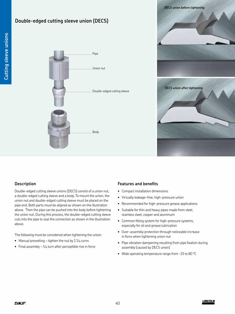
Double-edged cutting sleeve union (DECS)
Cutt
ing s
leev
e unio
ns
Description
Double-edged cutting sleeve unions (DECS) consist of a union nut,
a double-edged cutting sleeve and a body To mount the union, the
union nut and double-edged cutting sleeve must be placed on the
pipe end Both parts must be aligned as shown on the illustration
above Then the pipe can be pushed into the body before tightening
the union nut During this process, the double-edged cutting sleeve
cuts into the pipe to seal the connection as shown in the illustration
above
The following must be considered when tightening the union:
• Manual presetting – tighten the nut by 1 1/4 turns
• Final assembly – 1/4 turn after perceptible rise in force
Features and benefits
• Compact installation dimensions
• Virtually leakage-free, high-pressure union
• Recommended for high-pressure grease applications
• Suitable for thin and heavy pipes made from steel,
stainless steel, copper and aluminum
• Common fitting system for high-pressure systems,
especially for oil and grease lubrication
• Over-assembly protection through noticeable increase
in force when tightening union nut
• Pipe vibration dampening resulting from pipe fixation during
assembly (caused by DECS union)
• Wide operating temperature range from -25 to 80 °C
Double-edged cutting sleeve
Union nut
Pipe
Body
DECS union before tightening
DECS union after tightening
40

Cutt
ing s
leev
e fitt
ings
Cutt
ing s
leev
e unio
ns
Double-edged cutting sleeve unions
Double-edged cutting sleeves D acc. to DIN 3861/ISO 8434-1
Order number Designation SeriesTube ∅D L Material
Operating pressure max Weight
mm mm bar psi g lb
Steel, galvanized223-14083-3 CUTTING SLEEVE ST D 4-LL LL 4 6 Steel, galvanized 100 1 450 0,3 0.00223-12295-2 CUTTING SLEEVE ST D 6-LL LL 6 7 Steel, galvanized 100 1 450 0,8 0.00223-12295-5 CUTTING SLEEVE ST D 8-LL LL 8 7 Steel, galvanized 100 1 450 1 0.00223-12295-9 CUTTING SLEEVE ST D 10-LL LL 10 7 Steel, galvanized 100 1 450 1,3 0.00223-12295-3 CUTTING SLEEVE ST D 6-L/S L/S 6 9,5 Steel, galvanized 250 3 625 1 0.00223-12295-6 CUTTING SLEEVE ST D 8-L/S L/S 8 10 Steel, galvanized 250 3 625 1,7 0.00223-12295-8 CUTTING SLEEVE ST D 10-L/S L/S 10 10 Steel, galvanized 250 3 625 3,1 0.01223-12296-1 CUTTING SLEEVE ST D 12-L/S L/S 12 10,5 Steel, galvanized 250 3 625 3,5 0.01223-12296-9 CUTTING SLEEVE ST D 15-L L 15 10 Steel, galvanized 160 2 320 4,5 0.01223-12583-1 CUTTING SLEEVE ST D 18-L L 18 10,5 Steel, galvanized 160 2 320 5,5 0.01223-12296-8 CUTTING SLEEVE ST D 16-S S 16 10 Steel, galvanized 400 5 800 5,6 0.01223-12296-3 CUTTING SLEEVE ST D 20-S S 20 13 Steel, galvanized 400 5 800 11,4 0.03223-12296-5 CUTTING SLEEVE ST D 30-S S 30 13 Steel, galvanized 400 5 800 19,3 0.04
Stainless steel223-13639-5 CUTTING SLEEVE VA D 4-LL LL 4 6 Stainless steel 100 1 450 0,3 0.00223-13639-3 CUTTING SLEEVE VA D 6-L/S L/S 6 9,5 Stainless steel 250 3 625 1 0.00223-13639-2 CUTTING SLEEVE VA D 6-LL LL 6 7 Stainless steel 100 1 450 0,8 0.00223-13639-1 CUTTING SLEEVE VA D 8-L/S L/S 8 9,5 Stainless steel 250 3 625 1,7 0.00223-13639-4 CUTTING SLEEVE VA D 10-L/S L/S 10 9,5 Stainless steel 250 3 625 3,1 0.01223-13639-9 CUTTING SLEEVE VA D 12-L/S L/S 12 10 Stainless steel 250 3 625 3,5 0.01223-13639-7 CUTTING SLEEVE VA D 16-S S 16 9,5 Stainless steel 400 5 800 5,6 0.01223-13639-8 CUTTING SLEEVE VA D 20-S S 20 12,5 Stainless steel 400 5 800 11,4 0.03223-14092-5 CUTTING SLEEVE VA D 30-S S 30 12,5 Stainless steel 400 5 800 19,3 0.04
Zinc-nickel406-351 CUTTING SLEEVE ST D 6-LL Z3W LL 6 7 Zinc-nickel 100 1 450 1 0.00408-351 CUTTING SLEEVE ST D 8-LL Z3W LL 8 7 Zinc-nickel 100 1 450 1 0.00406-361 CUTTING SLEEVE ST D 6-L Z3W LL 6 11,5 Zinc-nickel 250 3 625 2 0.00408-361 CUTTING SLEEVE ST D 8-L Z3W LL 8 11,5 zinc-nickel 250 3 625 2 0.00
L
∅D
41

Cutt
ing s
leev
e unio
ns
Double-edged cutting sleeve unions
Union nuts M acc. to DIN 3861/ISO 8434-1
∅D
L
D1
Order number Designation SeriesTube ∅D D1 L Material
Operating pressure max Weight
mm mm mm mm bar psi g lb
Steel, galvanized223-13032-1 COUPLING NUT ST M 4-LL CF LL 4 M8×1 11 10 Steel, galvanized 100 1 450 4 0.01223-12374-9 COUPLING NUT ST M 6-LL CF LL 6 M10×1 12 12 Steel, galvanized 100 1 450 6 0.01223-13032-3 COUPLING NUT ST M 8-LL CF LL 8 M12×1 12 14 Steel, galvanized 100 1 450 7 0.02223-12374-6 COUPLING NUT ST M 10-LL CF LL 10 M14×1 12,5 17 Steel, galvanized 100 1 450 11 0.02223-12373-9 COUPLING NUT ST M 6-L CF L 6 M12×1,5 14,5 14 Steel, galvanized 250 3 625 10 0.02223-13032-4 COUPLING NUT ST M 8-L CF L 8 M14×1,5 14,5 17 Steel, galvanized 250 3 625 15 0.03223-13032-6 COUPLING NUT ST M 10-L CF L 10 M16×1,5 16 19 Steel, galvanized 250 3 625 18 0.04223-12373-2 COUPLING NUT ST M 12-L CF L 12 M18×1,5 16 22 Steel, galvanized 250 3 625 25 0.06223-12374-8 COUPLING NUT ST M 15-L CF L 15 M22×1,5 18 27 Steel, galvanized 250 3 625 42 0.09223-12374-7 COUPLING NUT ST M 18-L CF L 18 M26×1,5 18 32 Steel, galvanized 250 3 625 62 0.14223-13032-9 COUPLING NUT ST M 16-S CF S 16 M24×1,5 20,5 30 Steel, galvanized 400 5 800 66 0.15223-12373-6 COUPLING NUT ST M 20-S CF S 20 M30×2 24 36 Steel, galvanized 400 5 800 102 0.22223-12374-2 COUPLING NUT ST M 30-S CF S 30 M42×2 29 50 Steel, galvanized 400 5 800 219 0.48
Zinc-nickel406-352 COUPLING NUT ST M 6-LL Z3W LL 6 M10×1 11,5 12 Zinc-nickel 100 1 450 5 0.01408-352 COUPLING NUT ST M 8-LL Z3W LL 8 M12×1 12 14 Zinc-nickel 100 1 450 5 0.01406-362 COUPLING NUT ST M 6-L Z3W S 6 M12×1,5 14,5 14 Zinc-nickel 250 3 625 30 0.07408-362 COUPLING NUT ST M 8-L Z3W S 8 M14×1,5 14,5 17 Zinc-nickel 250 3 625 35 0.08406-362 COUPLING NUT ST M 6-L Z3W S 6 M12×1,5 14,5 14 Zinc-nickel 250 3 625 30 0.07408-362 Coupling nut ST M 8-L Z3W S 8 M14×1,5 14,5 17 Zinc-nickel 250 3 625 35 0.08
Stainless steel223-13638-6 COUPLING NUT VA M 4-LL LL 4 M8×1 11 10 Stainless steel 100 1 450 4 0.01223-13638-2 COUPLING NUT VA M 6-LL LL 6 M10×1 12 12 Stainless steel 100 1 450 6 0.01223-14082-5 COUPLING NUT VA M 6-L L 6 M12×1,5 14,5 14 Stainless steel 250 3 625 10 0.02223-13638-1 COUPLING NUT VA M 8-L L 8 M14×1,5 14,5 17 Stainless steel 250 3 625 15 0.03223-13638-3 COUPLING NUT VA M 10-L L 10 M16×1,5 16 19 Stainless steel 250 3 625 18 0.04223-14082-3 COUPLING NUT VA M 12-L L 12 M18×1,5 16 22 Stainless steel 250 3 625 25 0.06223-13638-7 COUPLING NUT VA M 16-S S 16 M24×1,5 20,5 30 Stainless steel 400 5 800 66 0.15223-13638-9 COUPLING NUT VA M 20-S S 20 M30×2 24 36 Stainless steel 400 5 800 102 0.22223-14082-6 COUPLING NUT VA M 30-S S 30 M42×2 29 50 Stainless steel 400 5 800 219 0.48
42
Cutt
ing s
leev
e unio
ns
Double-edged cutting sleeve unions
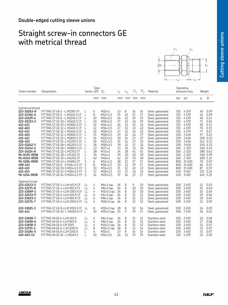
Straight screw-in connectors GE with metrical thread
D1∅D
L2L1
2 1
Order number Designation SeriesTube ∅D D1 L1 L2 1 2 Material
Operating pressure max Weight
mm mm mm mm mm mm bar psi g lb
Cylindrical thread223-10263-8 FITTING ST GE 6 -L M10X1 CF L 6 M10×1 23 8 14 14 Steel, galvanized 315 4 570 40 0.09223-12361-6 FITTING ST GE 6 -L M14X1 5 CF L 8 M12×1,5 25 12 17 17 Steel, galvanized 315 4 570 40 0.09223-14129-4 FITTING ST GE 8 -L M12X1 5 CF L 10 M14×1,5 26 12 19 19 Steel, galvanized 315 4 570 50 0.11223-10313-2 FITTING ST GE 10-L M14X1 5 CF L 10 M18×1,5 27 12 24 19 Steel, galvanized 315 4 570 71 0.16412-423 FITTING ST GE 10-L M18X1 5 CF L 12 M14×1,5 26 12 19 22 Steel, galvanized 315 4 570 60 0.13412-403 FITTING ST GE 12-L M14X1 5 CF L 12 M16×1,5 27 12 22 22 Steel, galvanized 315 4 570 70 0.15412-433 FITTING ST GE 12-L M16X1 5 CF L 12 M18×1,5 27 12 24 22 Steel, galvanized 315 4 570 77 0.17415-403 FITTING ST GE 12-L M18X1 5 CF L 15 M18×1,5 29 12 24 27 Steel, galvanized 250 3 626 97 0.21415-413 FITTING ST GE 15-L M18X1 5 CF L 15 M22×1,5 30 14 27 27 Steel, galvanized 250 3 626 100 0.22418-403 FITTING ST GE 15-L M22X1 5 CF L 18 M22×1,5 31 14 27 32 Steel, galvanized 250 3 626 143 0.32223-11242-5 FITTING ST GE 18-L M22X1 5 CF L 18 M18×1,5 30 12 27 32 Steel, galvanized 250 3 626 150 0.33223-11242-4 FITTING ST GE 18-L M18X1 5 CF L 22 M27×2 33 16 32 36 Steel, galvanized 160 2 320 160 0.35223-14214-8 FITTING ST GE 22-L M27X2 CF L 28 M33×2 34 18 41 41 Steel, galvanized 160 2 320 280 0.6296-0335-0058 FITTING ST GE 28-L M33X2 CF L 35 M42×2 39 20 50 50 Steel, galvanized 160 2 320 450 0.9996-0342-0058 FITTING ST GE 35-L M42X2 CF L 42 M48×2 42 22 55 60 Steel, galvanized 160 2 320 600 1.3296-1206-0058 FITTING ST GE 42-L M48X2 CF S 6 M12×1,5 28 12 17 17 Steel, galvanized 800 11 600 30 0.07408-413 FITTING ST GE 8 -S M14×1 5 CF S 8 M14×1,5 30 12 19 17 Steel, galvanized 800 11 600 66 0.15410-413 FITTING ST GE 10-S M16×1 5 CF S 10 M16×1,5 31 12 22 22 Steel, galvanized 800 11 600 87 0.19412-453 FITTING ST GE 12-S M18×1 5 CF S 12 M18×1,5 33 12 24 24 Steel, galvanized 630 9 140 111 0.2496-1214-0058 FITTING ST GE 14-S M20×1 5 CF S 14 M20×1,5 37 14 27 17 Steel, galvanized 630 9 140 140 0.31
Tapered thread223-12533-5 FITTING ST GE 4-LLM 6X1 K CF LL 4 M6×1 tap 26 8 9 10 Steel, galvanized 100 1 450 12 0.03223-12271-8 FITTING ST GE 4-LLM 8X1 K CF LL 4 M8×1 tap 26 8 10 10 Steel, galvanized 100 1 450 15 0.03223-13069-1 FITTING ST GE 4-LLM 10X1 K CF LL 4 M10×1 tap 26 8 10 10 Steel, galvanized 100 1 450 16 0.04223-12533-9 FITTING ST GE 6-LLM 6X1 K CF LL 6 M6×1 tap 26 8 11 12 Steel, galvanized 100 1 450 19 0.04223-13023-1 FITTING ST GE 6-LLM 8X1 K CF LL 6 M8×1 tap 26 8 11 12 Steel, galvanized 100 1 450 20 0.04223-12271-7 FITTING ST GE 6-LLM 10X1 K CF LL 6 M10×1 tap 26 8 11 12 Steel, galvanized 100 1 450 21 0.05
223-13021-1 FITTING ST GE 8-LLM 10X1 K CF LL 8 M10×1 tap 28 8 12 14 Steel, galvanized 100 1 450 24 0.05410-443 FITTING ST GE 10 -L M10X1 K CF L 10 M10×1 tap 25 9 19 17 Steel, galvanized 500 7 250 56 0.12
223-13658-7 FITTING VA GE 6-LLM 6X1 K LL 6 M6×1 tap 26 8 11 12 Stainless steel 100 1 450 26 0.06223-13658-6 FITTING VA GE 6-LLM 8X1 K LL 6 M8×1 tap 26 8 11 12 Stainless steel 100 1 450 27 0.06223-13658-5 FITTING VA GE 6-LM 10X1 LL 6 M10×1 tap 26 8 11 12 Stainless steel 100 1 450 31 0.07223-13715-1 FITTING VA GE 6-LLM 10X1 K LL 8 M10×1 tap 28 8 12 14 Stainless steel 100 1 450 33 0.07223-14184-5 FITTING VA GE 8-LLM 10X1 K L 6 M10×1 23 8 14 14 Stainless steel 100 1 450 31 0.07410-403-S3 FITTING VA GE 10 -L M14X1 5 L 10 M14×1,5 26 12 19 19 Stainless steel 315 4 570 24 0.05
43

Cutt
ing s
leev
e unio
ns
Double-edged cutting sleeve unions
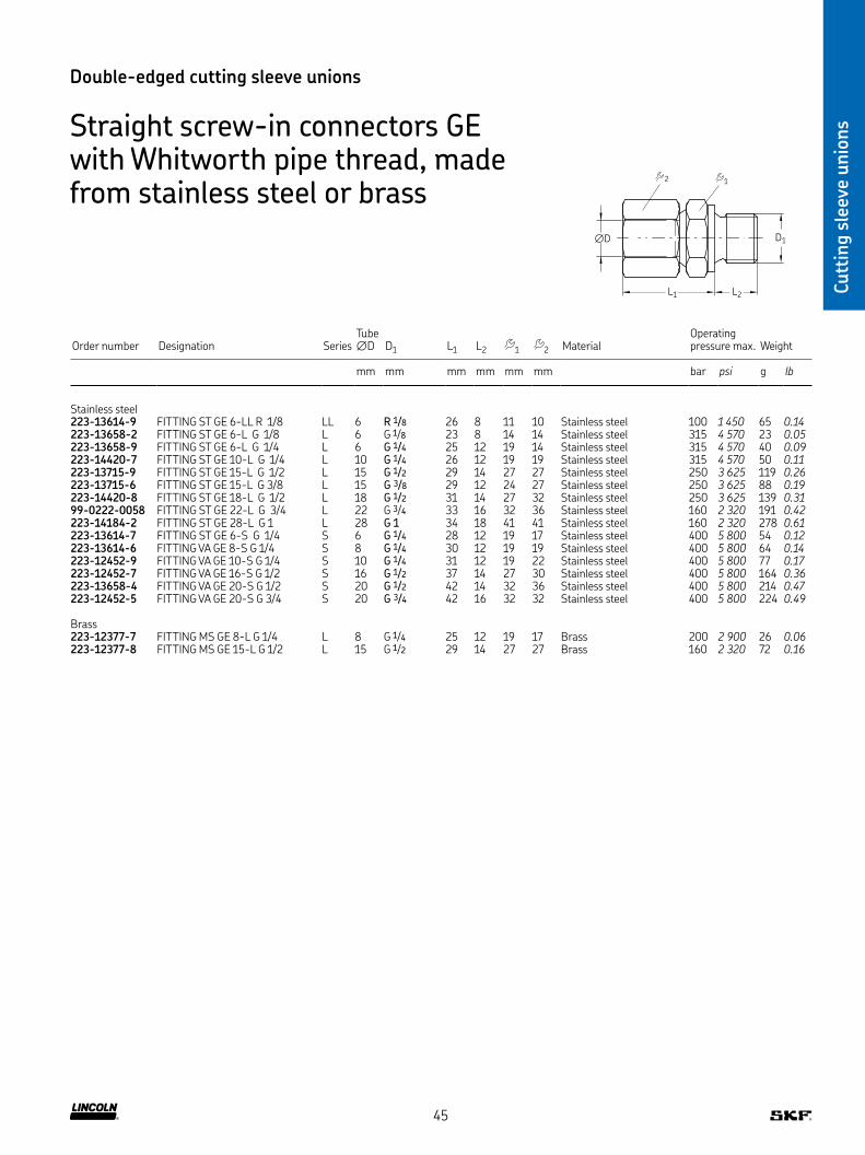
Straight screw-in connectors GE with Whitworth pipe thread
D1∅D
L2L1
2 1
Order number Designation SeriesTube ∅D D1 L1 L2 1 2 Material
Operating pressure max Weight
mm mm mm mm mm mm bar psi g lb
Cylindrical thread223-13016-3 FITTING ST ST GE 6-L G 1/8 CF L 6 G 1/8 23 8 14 14 Steel, galvanized 315 4 570 18 0.04223-12477-8 FITTING ST GE 6-L G 1/4 CF L 6 G 1/4 25 12 19 14 Steel, galvanized 315 4 570 35 0.08223-13766-6 FITTING ST GE 6-L G 3/8 CF L 6 G 3/8 26 12 22 14 Steel, galvanized 315 4 570 51 0.11223-10814-2 FITTING ST GE 8-L G 1/8 CF L 8 G 1/8 23 8 14 17 Steel, galvanized 315 4 570 24 0.05223-12477-6 FITTING ST GE 8-L G 1/4 CF L 8 G 1/4 25 12 19 17 Steel, galvanized 315 4 570 35 0.08223-10080-3 FITTING ST GE 8-L G 3/8 CF L 8 G 3/8 26 12 22 17 Steel, galvanized 315 4 570 53 0.12408-453W FITTING ST GE 8-L G 1/2 CF L 8 G 1/2 27 14 27 17 Steel, galvanized 315 4 570 82 0.18223-12272-9 FITTING ST GE 10-L G 1/4 CF L 10 G 1/4 26 12 19 19 Steel, galvanized 315 4 570 41 0.09223-14214-4 FITTING ST GE 10-L G 3/8 CF L 10 G 3/8 27 12 22 19 Steel, galvanized 315 4 570 55 0.12223-10313-7 FITTING ST GE 10-L G 1/2 CF L 10 G 1/2 28 14 27 19 Steel, galvanized 315 4 570 83 0.18223-12477-9 FITTING ST GE 12-L G 1/4 CF L 12 G 1/4 27 12 19 22 Steel, galvanized 315 4 570 46 0.10223-12360-8 FITTING ST GE 12-L G 3/8 CF L 12 G 3/8 27 12 22 22 Steel, galvanized 315 4 570 56 0.12412-453W FITTING ST GE 12-L G 1/2 CF L 12 G 1/2 28 14 27 22 Steel, galvanized 250 3 625 79 0.17415-443W FITTING ST GE 15-L G 3/4 CF L 15 G 3/4 30 16 32 27 Steel, galvanized 250 3 625 163 0.36223-12361-9 FITTING ST GE 15-L G 1/2 CF L 15 G 1/2 29 14 27 27 Steel, galvanized 250 3 625 119 0.26223-13621-8 FITTING ST GE 15-L G 3/8 CF L 15 G 3/8 29 12 24 27 Steel, galvanized 250 3 625 101 0.22223-13766-1 FITTING ST GE 18-L G 1/2 CF L 18 G 1/2 31 14 27 32 Steel, galvanized 250 3 625 139 0.31418-413W FITTING ST GE 18-L G 3/4 CF L 18 G 3/4 30 16 32 32 Steel, galvanized 250 3 625 178 0.39223-13749-3 FITTING ST GE 22-L G 1/2 CF L 22 G 1/2 33 14 32 36 Steel, galvanized 160 2 320 180 0.40223-13016-2 FITTING ST GE 22-L G 3/4 CF L 22 G 3/4 33 16 32 36 Steel, galvanized 160 2 320 191 0.42223-14214-9 FITTING ST GE 28-L G 3/4 CF L 28 G 3/4 34 16 41 41 Steel, galvanized 160 2 320 257 0.57223-13610-9 FITTING ST GE 28-L G 1 CF L 28 G 1 34 18 41 41 Steel, galvanized 160 2 320 287 0.63223-12477-1 FITTING ST GE 6-S G 1/4 CF S 6 G 1/4 28 12 19 17 Steel, galvanized 400 5 800 54 0.12223-12477-2 FITTING ST GE 8-S G 1/4 CF S 8 G 1/4 30 12 19 19 Steel, galvanized 400 5 800 60 0.13223-13016-6 FITTING ST GE 8-S G 3/8 CF S 8 G 3/8 30 12 22 19 Steel, galvanized 400 5 800 78 0.17223-13016-9 FITTING ST GE 10-S G 1/4 CF S 10 G 1/4 31 12 19 22 Steel, galvanized 400 5 800 77 0.17223-13016-4 FITTING ST GE 10-S G 3/8 CF S 10 G 3/8 31 12 22 22 Steel, galvanized 400 5 800 90 0.20223-13016-7 FITTING ST GE 12-S G 3/8 CF S 12 G 3/8 33 12 22 24 Steel, galvanized 400 5 800 96 0.21223-14129-3 FITTING ST GE 12-S G 1/2 CF S 12 G 1/2 24 14 27 24 Steel, galvanized 400 5 800 91 0.2096-1114-0058 FITTING ST GE 14-S G 1/2 CF S 14 G 1/2 27 14 27 27 Steel, galvanized 400 5 800 153 0.34223-13749-5 FITTING ST GE 16-S G 3/8 CF S 16 G 3/8 36 12 27 30 Steel, galvanized 400 5 800 165 0.36223-13621-1 FITTING ST GE 16-S G 1/2 CF S 16 G 1/2 37 14 27 30 Steel, galvanized 400 5 800 164 0.36223-12360-6 FITTING ST GE 20-S G 1/2 CF S 20 G 1/2 42 14 32 36 Steel, galvanized 400 5 800 214 0.47223-12359-6 FITTING ST GE 20-S G 3/4 CF S 20 G 3/4 42 16 32 32 Steel, galvanized 400 5 800 224 0.49223-14214-2 FITTING ST GE 6-L 1/8NPT CF L 6 1/8 NPT 32 10 11 12 Steel, galvanized 100 1 450 24 0.05223-12273-5 FITTING ST GE 8-L 1/4NPT CF L 8 1/4 NPT 38 14 5 17 17 Steel, galvanized 315 4 570 42 0.09223-13096-2 FITTING ST GE 10-S 1/4NPT CF S 10 1/4 NPT 44 14 5 19 22 Steel, galvanized 630 9 140 77 0.17223-14214-5 FITTING ST GE 20-S 1/2NPT CF S 20 1/2 NPT 59 19 5 32 36 Steel, galvanized 400 5 800 235 0.52
Tapered thread223-12270-8 FITTING ST GE 4-LL R 1/8K CF LL 4 R 1/8 26 8 11 10 Steel, galvanized 100 1) 1 450 1) 12 0.03223-12270-7 FITTING ST GE 6-LL R 1/8K CF LL 6 R 1/8 26 8 11 12 Steel, galvanized 100 1) 1 450 1) 15 0.03223-12270-9 FITTING ST GE 8-LL R 1/8K CF LL 8 R 1/8 28 8 12 14 Steel, galvanized 100 1) 1 450 1) 18 0.04223-13621-6 FITTING ST GE 8-LL R 1/4K CF LL 8 R 1/4 32 12 14 14 Steel, galvanized 100 1) 1 450 1) 26 0.0696-5911-0058 FITTING ST GE10-LL R 1/4K CF LL 10 R 1/4 32 12 14 17 Steel, galvanized 100 1) 1 450 1) 36 0.0896-5912-0058 FITTING ST GE12-LL R 1/4K CF LL 12 R 1/4 32 12 17 19 Steel, galvanized 100 1) 1 450 1) 65 0.1496-5913-0058 FITTING ST GE12-LL R 3/8K CF LL 12 R 3/8 32 12 17 19 Steel, galvanized 100 1) 1 450 1) 55 0.12410-443W FITTING ST GE10-L R 1/8K CF L 10 R 1/8 34 8 14 17 Steel, galvanized 315 4 570 42 0.09
1) In grease lubrication systems fittings are permittted for operating pressures up to 350 bar, 5080 psi
44
Cutt
ing s
leev
e unio
ns
Double-edged cutting sleeve unions
Straight screw-in connectors GE with Whitworth pipe thread, made from stainless steel or brass
Order number Designation SeriesTube ∅D D1 L1 L2 1 2 Material
Operating pressure max Weight
mm mm mm mm mm mm bar psi g lb
Stainless steel223-13614-9 FITTING ST GE 6-LL R 1/8 LL 6 R 1/8 26 8 11 10 Stainless steel 100 1 450 65 0.14223-13658-2 FITTING ST GE 6-L G 1/8 L 6 G 1/8 23 8 14 14 Stainless steel 315 4 570 23 0.05223-13658-9 FITTING ST GE 6-L G 1/4 L 6 G 1/4 25 12 19 14 Stainless steel 315 4 570 40 0.09223-14420-7 FITTING ST GE 10-L G 1/4 L 10 G 1/4 26 12 19 19 Stainless steel 315 4 570 50 0.11223-13715-9 FITTING ST GE 15-L G 1/2 L 15 G 1/2 29 14 27 27 Stainless steel 250 3 625 119 0.26223-13715-6 FITTING ST GE 15-L G 3/8 L 15 G 3/8 29 12 24 27 Stainless steel 250 3 625 88 0.19223-14420-8 FITTING ST GE 18-L G 1/2 L 18 G 1/2 31 14 27 32 Stainless steel 250 3 625 139 0.3199-0222-0058 FITTING ST GE 22-L G 3/4 L 22 G 3/4 33 16 32 36 Stainless steel 160 2 320 191 0.42223-14184-2 FITTING ST GE 28-L G 1 L 28 G 1 34 18 41 41 Stainless steel 160 2 320 278 0.61223-13614-7 FITTING ST GE 6-S G 1/4 S 6 G 1/4 28 12 19 17 Stainless steel 400 5 800 54 0.12223-13614-6 FITTING VA GE 8-S G 1/4 S 8 G 1/4 30 12 19 19 Stainless steel 400 5 800 64 0.14223-12452-9 FITTING VA GE 10-S G 1/4 S 10 G 1/4 31 12 19 22 Stainless steel 400 5 800 77 0.17223-12452-7 FITTING VA GE 16-S G 1/2 S 16 G 1/2 37 14 27 30 Stainless steel 400 5 800 164 0.36223-13658-4 FITTING VA GE 20-S G 1/2 S 20 G 1/2 42 14 32 36 Stainless steel 400 5 800 214 0.47223-12452-5 FITTING VA GE 20-S G 3/4 S 20 G 3/4 42 16 32 32 Stainless steel 400 5 800 224 0.49
Brass223-12377-7 FITTING MS GE 8-L G 1/4 L 8 G 1/4 25 12 19 17 Brass 200 2 900 26 0.06223-12377-8 FITTING MS GE 15-L G 1/2 L 15 G 1/2 29 14 27 27 Brass 160 2 320 72 0.16
D1∅D
L2L1
2 1
45

Cutt
ing s
leev
e unio
ns
Double-edged cutting sleeve unions
Straight screw-in glands XGE
L1
D1 D2
L2
Order number Designation SeriesTube ∅ D1 D2 L1 L2 Material
Operating pressure max
Weight
mm mm mm mm mm mm bar psi g lb
223-13766-9 FITTING ST XGE 6-LL M 10X1,0K CF LL 6 M10×1 tap M10×1 8 20 11 Steel, galvanized 100 1 450 17 0.04223-14129-1 FITTING ST XGE 6-LL M 8X1,0K CF LL 6 M8×1 tap M10×1 8 20 11 Steel, galvanized 100 1 450 17 0.04223-14129-2 FITTING ST XGE 6-LL R 1/8K CF LL 6 R 1/8 M12×1,5 8 20 11 Steel, galvanized 100 1 450 18 0.04223-14234-7 FITTING ST XGE 6-L M 10X1,0 CF L 6 M10×1 M12×1,5 8 23,5 14 Steel, galvanized 500 7 250 20 0.04408-313 FITTING ST XGE 8-L M 14X1,5 CF L 8 M14×1 5 M14×1,5 9 36 17 Steel, galvanized 500 7 250 31 0.07410-313 FITTING ST XGE10-L M 16X1,5 CF L 10 M16×1 5 M16×1,5 9 31,5 22 Steel, galvanized 500 7 250 40 0.09223-14304-2 FITTING ST XGE 10-L M 14X1,5 CF L 10 M14×1 5 M16×1,5 9 30,0 19 Steel, galvanized 500 7 250 40 0.09223-14304-7 FITTING ST XGE 12-L M 14X1,5 CF L 12 M14×1 5 M18×1,5 12 30,0 19 Steel, galvanized 400 5 800 55 0.12223-13610-8 FITTING ST XGE 18-L M 22X1,5 CF L 18 M22×1 5 M26×1,5 14 36,0 27 Steel, galvanized 315 4 570 148 0.33223-11229-9 FITTING ST XGE 8-L G 1/4A CF L 8 G 1/4 M14×1,5 12 30 19 Steel, galvanized 500 7 250 35 0.08223-14234-4 FITTING ST XGE10-L G 1/8A CF L 10 G 1/8 M18×1,5 12 34 17 Steel, galvanized 500 7 250 33 0.07223-10055-9 FITTING ST XGE10-L G 3/8A CF L 10 G 3/8 M18×1,5 12 31,5 22 Steel, galvanized 500 7 250 55 0.12223-14418-7 FITTING ST XGE18-L G 1/2A CF L 18 G 1/2 M26×1,5 14 36 27 Steel, galvanized 400 5 800 139 0.31223-11089-3 FITTING ST XGE10-S G 1/4A CF S 10 G 1/4 M18×1,5 12 30 19 Steel, galvanized 800 11 600 41 0.09223-14304-5 FITTING ST XGE20-S G 1/2A CF S 20 G 1/2 M30×2 14 45 32 Steel, galvanized 420 6 090 262 0.58
Straight tube-to-tube connectors G
∅D ∅D
L
Order number Designation Series Tube ∅D L Material Operating pressure max
Weight
mm mm mm bar psi g lb
Steel, galvanized223-12531-8 FITTING ST G 4-LL CF LL 4 31 10 Steel, galvanized 100 1 450 13 0.03223-12482-9 FITTING ST G 6-LL CF LL 6 32 12 Steel, galvanized 100 1 450 21 0.05223-12531-9 FITTING ST G 8-LL CF LL 8 35 14 Steel, galvanized 100 1 450 26 0.06223-12531-2 FITTING ST G 10-L CF L 10 42 19 Steel, galvanized 500 7 250 65 0.14223-13732-8 FITTING ST G 12-L CF L 12 43 22 Steel, galvanized 500 7 250 84 0.19223-12531-6 FITTING ST G 15-L CF L 15 46 27 Steel, galvanized 400 5 800 145 0.32223-13732-4 FITTING ST G 18-L CF L 18 48 32 Steel, galvanized 400 5 800 205 0.45223-13049-3 FITTING ST G 10-S CF S 10 49 22 Steel, galvanized 800 11 600 112 0.25223-12531-4 FITTING ST G 16-S CF S 16 57 30 Steel, galvanized 630 9 140 234 0.52223-12363-2 FITTING ST G 20-S CF S 20 66 36 Steel, galvanized 420 6 090 369 0.81223-12363-6 FITTING ST G 30-S CF S 30 80 50 Steel, galvanized 420 6 090 806 1.78
Stainless steel223-13615-5 FITTING VA G 6-L L 6 39 14 Stainless steel 315 4 570 36 0.08223-13615-3 FITTING VA G 8-L L 8 40 17 Stainless steel 315 4 570 50 0.11223-13615-6 FITTING VA G 10-L L 10 42 19 Stainless steel 315 4 570 37 0.08223-12454-8 FITTING VA G 15-L L 15 46 27 Stainless steel 315 4 570 145 0.32223-12454-1 FITTING VA G 10-S S 10 49 22 Stainless steel 630 9 140 112 0.25223-12454-6 FITTING VA G 16-S S 16 57 30 Stainless steel 400 5 800 234 0.52223-12454-3 FITTING VA G 20-S S 20 66 36 Stainless steel 400 5 800 369 0.81223-12454-5 FITTING VA G 30-S S 30 80 50 Stainless steel 400 5 800 806 1.78
46

Cutt
ing s
leev
e unio
ns
Double-edged cutting sleeve unions
Straight tube-to-tube reducing connectors GR
2 1
∅D1∅D
L
Order number Designation SeriesTube ∅D
Tube ∅D1 L 1 2 Material
Operating pressure max Weight
mm mm mm mm mm bar psi g lb
Steel, galvanized223-12542-2 FITTING ST GR 6/ 4-LL CF LL 6 4 32 10 12 Steel, galvanized 100 1 450 7 0.02504-412 FITTING ST GR 8/ 4 L CF L 8 4 34 10 14 Steel, galvanized 100 1 450 9 0.02223-13705-5 FITTING ST GR 8/6 L CF L 8 6 40 14 17 Steel, galvanized 500 7 250 16 0.04223-13622-3 FITTING ST GR 10/6 L CF L 10 6 41 14 19 Steel, galvanized 500 7 250 21 0.05223-13024-4 FITTING ST GR 10/8 L CF L 10 8 41 17 19 Steel, galvanized 500 7 250 21 0.05223-10986-1 FITTING ST GR 12/6 L CF L 12 6 42 14 22 Steel, galvanized 400 5 800 26 0.06223-13622-7 FITTING ST GR 12/8 L CF L 12 8 42 17 22 Steel, galvanized 400 5 800 26 0.06510-410 FITTING ST GR 12/10 L CF L 12 10 43 19 22 Steel, galvanized 400 5 800 29 0.06223-13024-8 FITTING ST GR 15/8 L CF L 15 8 45 17 27 Steel, galvanized 400 5 800 42 0.09223-12542-7 FITTING ST GR 15/10 L CF L 15 10 45 19 27 Steel, galvanized 400 5 800 46 0.10223-12452-8 FITTING ST GR 15/12 L CF L 15 12 45 22 27 Steel, galvanized 400 5 800 45 0.10510-413 FITTING ST GR 18/10 L CF L 18 10 46 19 32 Steel, galvanized 400 5 800 65 0.14512-412 FITTING ST GR 18/12 L CF L 18 12 46 22 32 Steel, galvanized 400 5 800 64 0.14515-410 FITTING ST GR 18/15 L CF L 18 15 48 27 32 Steel, galvanized 400 5 800 65 0.14223-13622-1 FITTING ST GR 16/10 S CF S 16 10 54 22 30 Steel, galvanized 630 9 140 80 0.18223-12364-4 FITTING ST GR 20/10 S CF S 20 10 60 22 36 Steel, galvanized 420 6 090 129 0.28223-13024-1 FITTING ST GR 30/20 S CF S 30 20 74 36 50 Steel, galvanized 420 6 090 299 0.66
Stainless steel223-13619-9 FITTING VA GR 16/10 S S 16 10 54 22 30 Stainless steel 400 5 800 80 0.18223-13619-2 FITTING VA GR 20/10 S S 20 10 60 22 36 Stainless steel 400 5 800 129 0.28223-13791-5 FITTING VA GR 30/20 S S 30 20 74 36 50 Stainless steel 400 5 800 299 0.66
47

Cutt
ing s
leev
e unio
ns
Double-edged cutting sleeve unions
Union studs GZ
∅D1∅D1
L
Order number Designation Series Tube ∅D D1 L Material Operating pressure max
Weight
mm mm mm mm bar psi g lb
Steel, galvanized223-10550-2 STUD ST GZ 6-L CF L 6 M14×1,5 33 14 Steel, galvanized 500 7 250 28 0.06223-10550-8 STUD ST GZ 8-L CF L 8 M14×1,5 33 17 Steel, galvanized 500 7 250 41 0.09223-14253-2 STUD ST GZ10-L CF L 10 M16×1,5 34 19 Steel, galvanized 500 7 250 53 0.12223-10550-6 STUD ST GZ12-L CF L 12 M18×1,5 34 22 Steel, galvanized 400 5 800 71 0.16223-14253-5 STUD ST GZ15-L CF L 15 M22×1,5 39 27 Steel, galvanized 400 5 800 129 0.28223-10550-1 STUD ST GZ 6-S CF S 6 M14×1,5 33 17 Steel, galvanized 800 11 600 41 0.09223-14253-4 STUD ST GZ10-S CF S 10 M18×1,5 35 22 Steel, galvanized 800 11 600 74 0.16223-14253-1 STUD ST GZ16-S CF S 16 M24×1,5 42 30 Steel, galvanized 630 9 140 172 0.38223-14497-8 STUD ST GZ20-S CF S 20 M30×2 48 36 Steel, galvanized 420 6 090 261 0.58223-14253-3 STUD ST GZ30-S CF S 30 M42×2 62 50 Steel, galvanized 420 6 090 605 1.33
Stainless steel223-14497-1 STUD VA GZ10-L L 10 M16×1,5 34 19 Stainless steel 315 4 570 53 0.12223-14497-3 STUD VA GZ16-S S 16 M24×1,5 42 30 Stainless steel 400 5 800 172 0.38223-14497-4 STUD VA GZ20-S S 20 M30×2 48 36 Stainless steel 400 5 800 261 0.58
Straight tube studs EGE
∅D1 ∅D∅D2
L1L2
2 1
Order number Designation SeriesTube ∅D ∅D1 ∅D2 L1 L2 1 2 Material
Operating pressure max Weight
mm mm mm mm mm mm mm bar psi g lb
223-14130-7 TUBE STUD ST EGE 6-L G 1/8-ED CF L 6 G 1/8 14 24,5 8 14 14 Steel, galvanized 500 7 250 27 0.06223-13686-1 TUBE STUD ST EGE10-L G 1/4-ED CF L 10 G 1/4 19 27,5 12 19 19 Steel, galvanized 500 7 250 54 0.12223-14130-9 TUBE STUD ST EGE10-L G 3/8-ED CF L 10 G 3/8 22 29 12 22 19 Steel, galvanized 400 5 800 70 0.15223-14187-4 TUBE STUD ST EGE10-L M14×1 5-ED CF L 10 M14×1,5 19 27,5 12 19 19 Steel, galvanized 500 7 250 49 0.11223-10563-8 TUBE STUD ST EGE12-L M16X1 5-ED CF L 12 M16×1,5 22 30,5 12 22 22 Steel, galvanized 400 5 800 67 0.15223-14187-4 TUBE STUD ST EGE10-L 1/4 NPT-ED CF L 10 1/4 NPT 19 27,5 12 19 19 Steel, galvanized 315 4 570 44 0.10223-10563-5 TUBE STUD ST EGE12-L G 1/4-ED CF L 12 G 1/4 19 27,5 12 19 22 Steel, galvanized 400 5 800 61 0.13223-14130-2 TUBE STUD ST EGE15-L G 1/2-ED CF L 15 G 1/2 27 32 14 27 27 Steel, galvanized 400 5 800 114 0.25223-10563-7 TUBE STUD ST EGE 6-S G 1/4-ED CF S 6 G 1/4 19 27 12 19 17 Steel, galvanized 800 11 600 53 0.12223-10563-6 TUBE STUD ST EGE12-S G 3/8-ED CF S 12 G 3/8 22 34 12 22 24 Steel, galvanized 630 9 140 95 0.21223-14130-2 TUBE STUD ST EGE30-S 3/4 NPT-ED CF S 20 3/4 NPT 32 43 16 32 36 Steel, galvanized 400 5 800 254 0.56
48
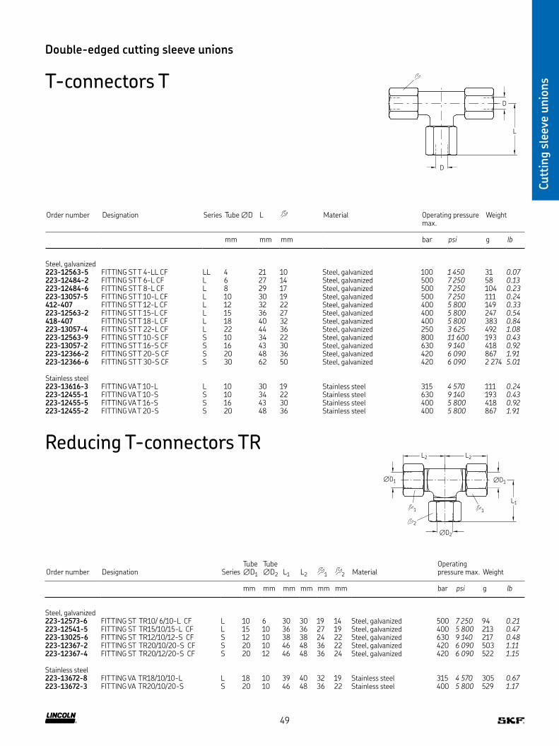
Cutt
ing s
leev
e unio
ns
Double-edged cutting sleeve unions
T-connectors T
D
D
L
Order number Designation Series Tube ∅D L Material Operating pressuremax
Weight
mm mm mm bar psi g lb
Steel, galvanized223-12563-5 FITTING ST T 4-LL CF LL 4 21 10 Steel, galvanized 100 1 450 31 0.07223-12484-2 FITTING ST T 6-L CF L 6 27 14 Steel, galvanized 500 7 250 58 0.13223-12484-6 FITTING ST T 8-L CF L 8 29 17 Steel, galvanized 500 7 250 104 0.23223-13057-5 FITTING ST T 10-L CF L 10 30 19 Steel, galvanized 500 7 250 111 0.24412-407 FITTING ST T 12-L CF L 12 32 22 Steel, galvanized 400 5 800 149 0.33223-12563-2 FITTING ST T 15-L CF L 15 36 27 Steel, galvanized 400 5 800 247 0.54418-407 FITTING ST T 18-L CF L 18 40 32 Steel, galvanized 400 5 800 383 0.84223-13057-4 FITTING ST T 22-L CF L 22 44 36 Steel, galvanized 250 3 625 492 1.08223-12563-9 FITTING ST T 10-S CF S 10 34 22 Steel, galvanized 800 11 600 193 0.43223-13057-2 FITTING ST T 16-S CF S 16 43 30 Steel, galvanized 630 9 140 418 0.92223-12366-2 FITTING ST T 20-S CF S 20 48 36 Steel, galvanized 420 6 090 867 1.91223-12366-6 FITTING ST T 30-S CF S 30 62 50 Steel, galvanized 420 6 090 2 274 5.01
Stainless steel223-13616-3 FITTING VA T 10-L L 10 30 19 Stainless steel 315 4 570 111 0.24223-12455-1 FITTING VA T 10-S S 10 34 22 Stainless steel 630 9 140 193 0.43223-12455-5 FITTING VA T 16-S S 16 43 30 Stainless steel 400 5 800 418 0.92223-12455-2 FITTING VA T 20-S S 20 48 36 Stainless steel 400 5 800 867 1.91
∅D1 ∅D1
∅D2
L1
L2
2
1 1
L2
Order number Designation SeriesTube ∅D1
Tube ∅D2 L1 L2 1 2 Material
Operating pressure max Weight
mm mm mm mm mm mm bar psi g lb
Steel, galvanized223-12573-6 FITTING ST TR10/ 6/10-L CF L 10 6 30 30 19 14 Steel, galvanized 500 7 250 94 0.21223-12541-5 FITTING ST TR15/10/15-L CF L 15 10 36 36 27 19 Steel, galvanized 400 5 800 213 0.47223-13025-6 FITTING ST TR12/10/12-S CF S 12 10 38 38 24 22 Steel, galvanized 630 9 140 217 0.48223-12367-2 FITTING ST TR20/10/20-S CF S 20 10 46 48 36 22 Steel, galvanized 420 6 090 503 1.11223-12367-4 FITTING ST TR20/12/20-S CF S 20 12 46 48 36 24 Steel, galvanized 420 6 090 522 1.15
Stainless steel223-13672-8 FITTING VA TR18/10/10-L L 18 10 39 40 32 19 Stainless steel 315 4 570 305 0.67223-13672-3 FITTING VA TR20/10/20-S S 20 10 46 48 36 22 Stainless steel 400 5 800 529 1.17
Reducing T-connectors TR
49

Cutt
ing s
leev
e unio
ns
Double-edged cutting sleeve unions
Elbow connectors W
D
D
L
Elbow screw-in connectors WE with metrical thread
D1
D
L1
L2
Order number Designation Series Tube ∅D L Material Operating pressuremax
Weight
mm mm mm bar psi g lb
Steel, galvanized223-12483-2 FITTING ST W 6-L CF L 6 27 14 Steel, galvanized 500 7 250 41 0.09223-12483-5 FITTING ST W 8-L CF L 8 29 17 Steel, galvanized 500 7 250 60 0.13223-12483-8 FITTING ST W 10-L CF L 10 30 19 Steel, galvanized 500 7 250 75 0.17223-12562-2 FITTING ST W 15-L CF L 15 36 27 Steel, galvanized 400 5 800 128 0.28443-218-001 FITTING ST W 18-L CF L 18 40 32 Steel, galvanized 400 5 800 208 0.46443-290-001 FITTING ST W 22-L CF L 22 44 36 Steel, galvanized 250 3 625 267 0.59223-12562-7 FITTING ST W 10-S CF S 10 34 22 Steel, galvanized 800 11 600 133 0.29223-12280-9 FITTING ST W 12-S CF S 12 38 24 Steel, galvanized 630 9 140 175 0.39223-12562-8 FITTING ST W 16-S CF S 16 43 30 Steel, galvanized 630 9 140 232 0.51223-12365-2 FITTING ST W 20-S CF S 20 48 36 Steel, galvanized 420 6 090 333 0.73
Stainless steel223-14424-5 FITTING VA W 8-L L 8 29 17 Stainless steel 315 4 570 60 0.13223-13675-6 FITTING VA W 10-S S 10 34 22 Stainless steel 630 9 140 133 0.29223-13675-2 FITTING VA W 20-S S 20 48 36 Stainless steel 400 5 800 333 0.73
Order number Designation SeriesTube ∅D ∅D1 L1 L2 Material
Operating pressure max Weight
mm mm mm mm mm bar psi g lb
Steel, galvanized223-13023-3 FITTING ST WE 6-LL M8×1K CF LL 6 M8×1 21 8 12 Steel, galvanized 100 1 450 24 0.05223-13021-3 FITTING ST WE 6-LL M10×1K CF LL 6 M10×1 15 8 12 Steel, galvanized 100 1 450 24 0.05223-12362-4 FITTING ST WE 8-LL M10×1K CF LL 8 M10×1 17 8 14 Steel, galvanized 100 1 450 33 0.07223-12485-8 FITTING ST WE 6-L M10×1K CF L 6 M10×1 19 8 14 Steel, galvanized 315 4 570 41 0.09223-12362-8 FITTING ST WE 8-L M12×1 5K CF L 8 M12×1,5 21 12 17 Steel, galvanized 315 4 570 63 0.14406-405 FITTING ST WE10-L M14×1 5K CF L 10 M14×1,5 22 12 19 Steel, galvanized 315 4 570 83 0.18412-405 FITTING ST WE12-L M16×1 5K CF L 12 M16×1,5 24 12 22 Steel, galvanized 315 4 570 117 0.26415-405 FITTING ST WE15-L M18×1 5K CF L 15 M18×1,5 28 12 27 Steel, galvanized 315 4 570 125 0.28223-12485-2 FITTING ST WE 10-S M16×1 5K CF S 10 M16×1,5 25 12 22 Steel, galvanized 400 5 800 123 0.27
Stainless steel404-405-S3 FITTING VA WE 4-LL M8×1K LL 4 M8×1 15 8 10 Stainless steel 100 1 450 18 0.04223-13677-2 FITTING VA WE 6-LL M8×1K LL 6 M8×1 21 8 12 Stainless steel 100 1 450 24 0.05
50

Cutt
ing s
leev
e unio
ns
Order number Designation SeriesTube ∅D ∅D1 L1 L2 Material
Operating pressure max Weight
mm mm mm mm mm bar psi g lb
Steel, galvanized223-13021-4 FITTING ST WE 4-LL R 1/8K CF LL 4 R 1/8 15 8 10 Steel, galvanized 100 1 450 21 0.05223-13021-6 FITTING ST WE 8-LL R 1/8K CF LL 8 R 1/8 17 8 14 Steel, galvanized 100 1 450 32 0.0796-6112-0058 FITTING ST WE12-LL R 1/4K CF LL 12 R 1/4 19 12 19 Steel, galvanized 100 1 450 61 0.13223-13048-1 FITTING ST WE 6-L R 1/8K CF L 6 R 1/8 19 8 14 Steel, galvanized 315 4 570 42 0.09223-12380-6 FITTING ST WE 6-L R 1/4K CF L 6 R 1/4 21 12 14 Steel, galvanized 315 4 570 59 0.13408-425W FITTING ST WE 8-L R 1/8K CF L 8 R 1/8 21 8 17 Steel, galvanized 315 4 570 66 0.15223-14240-5 FITTING ST WE 8-L R 1/4K CF L 8 R 1/4 21 12 17 Steel, galvanized 315 4 570 63 0.14223-13048-5 FITTING ST WE 10-L R 1/4K CF L 10 R 1/4 22 12 19 Steel, galvanized 315 4 570 82 0.18412-405W FITTING ST WE 12-L R 3/8K CF L 12 R 3/8 24 12 22 Steel, galvanized 315 4 570 116 0.26223-13021-7 FITTING ST WE 15-L R 1/2K CF L 15 R 1/2 28 14 27 Steel, galvanized 315 4 570 141 0.31418-405W FITTING ST WE 18-L R 1/2K CF L 18 R 1/2 31 14 32 Steel, galvanized 315 4 570 230 0.51223-13048-6 FITTING ST WE 10-S R 3/8K CF S 10 R 3/8 25 12 22 Steel, galvanized 400 5 800 138 0.3096-1412-0058 FITTING ST WE 12-S R 3/8K CF S 12 R 3/8 29 12 24 Steel, galvanized 400 5 800 164 0.36223-13048-8 FITTING ST WE 16-S R 1/2K CF S 16 R 1/2 33 14 30 Steel, galvanized 400 5 800 232 0.51
Stainless steel223-13620-8 FITTING VA WE 6-L R 1/8K L 6 R 1/8 19 8 14 Stainless steel 315 4 570 42 0.09223-13677-5 FITTING VA WE 8-L R 1/4K L 8 R 1/4 21 12 17 Stainless steel 315 4 570 63 0.14223-12453-1 FITTING VA WE 10-L R 1/4K L 10 R 1/4 22 12 19 Stainless steel 315 4 570 82 0.18
D1
D
L1
L2
Double-edged cutting sleeve unions
Elbow screw-in connectors WE with Whitworth pipe thread
51
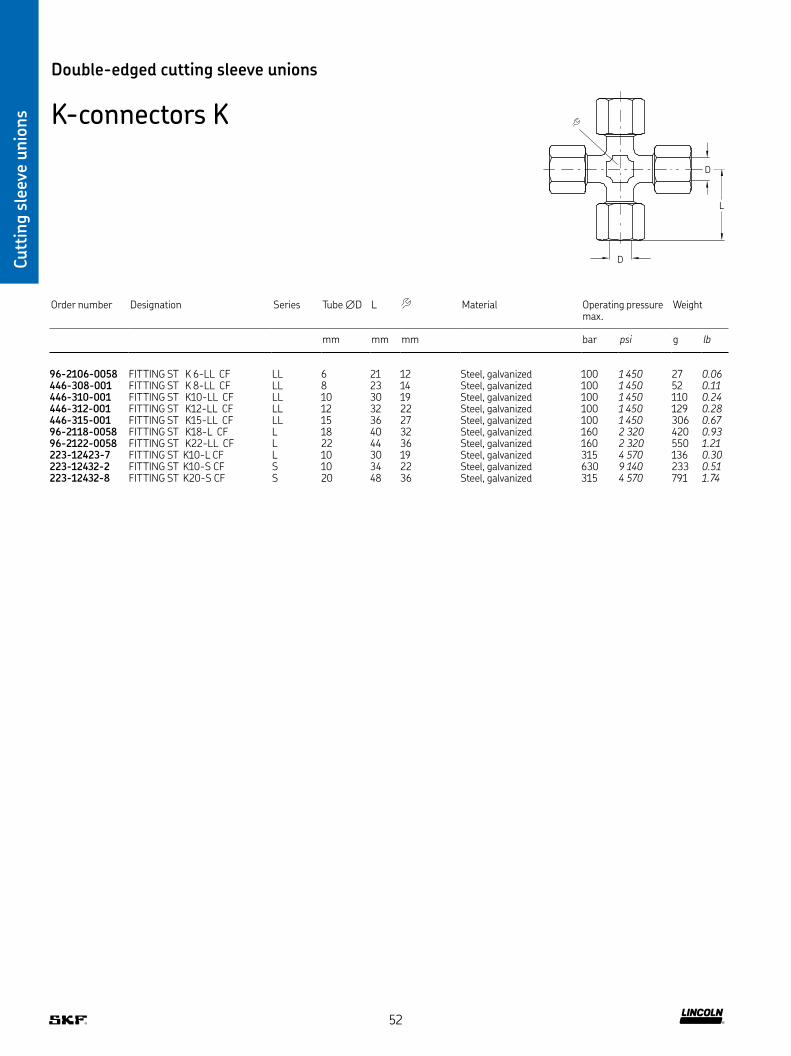
Cutt
ing s
leev
e unio
ns
D
D
L
Double-edged cutting sleeve unions
K-connectors K
Order number Designation Series Tube ∅D L Material Operating pressuremax
Weight
mm mm mm bar psi g lb
96-2106-0058 FITTING ST K 6-LL CF LL 6 21 12 Steel, galvanized 100 1 450 27 0.06446-308-001 FITTING ST K 8-LL CF LL 8 23 14 Steel, galvanized 100 1 450 52 0.11446-310-001 FITTING ST K10-LL CF LL 10 30 19 Steel, galvanized 100 1 450 110 0.24446-312-001 FITTING ST K12-LL CF LL 12 32 22 Steel, galvanized 100 1 450 129 0.28446-315-001 FITTING ST K15-LL CF LL 15 36 27 Steel, galvanized 100 1 450 306 0.6796-2118-0058 FITTING ST K18-L CF L 18 40 32 Steel, galvanized 160 2 320 420 0.9396-2122-0058 FITTING ST K22-LL CF L 22 44 36 Steel, galvanized 160 2 320 550 1.21223-12423-7 FITTING ST K10-L CF L 10 30 19 Steel, galvanized 315 4 570 136 0.30223-12432-2 FITTING ST K10-S CF S 10 34 22 Steel, galvanized 630 9 140 233 0.51223-12432-8 FITTING ST K20-S CF S 20 48 36 Steel, galvanized 315 4 570 791 1.74
52
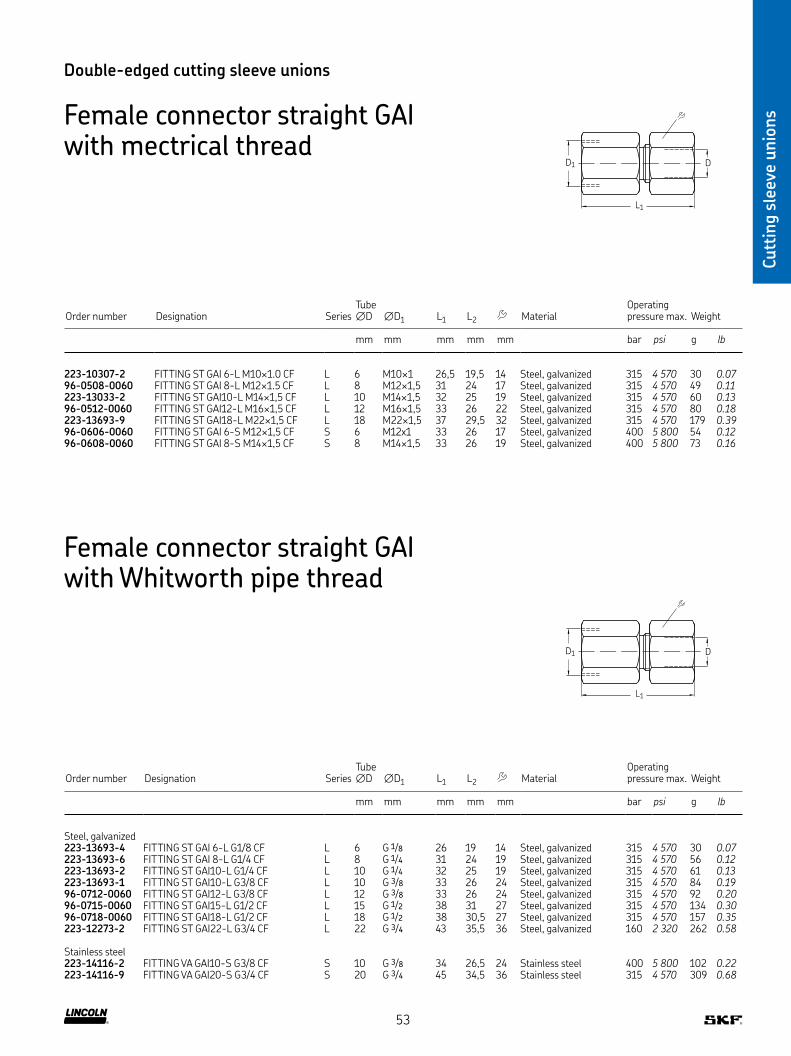
Cutt
ing s
leev
e unio
ns
Double-edged cutting sleeve unions
Female connector straight GAI with mectrical thread
DD1
L1
Order number Designation SeriesTube ∅D ∅D1 L1 L2 Material
Operating pressure max Weight
mm mm mm mm mm bar psi g lb
223-10307-2 FITTING ST GAI 6-L M10×1 0 CF L 6 M10×1 26,5 19,5 14 Steel, galvanized 315 4 570 30 0.0796-0508-0060 FITTING ST GAI 8-L M12×1 5 CF L 8 M12×1,5 31 24 17 Steel, galvanized 315 4 570 49 0.11223-13033-2 FITTING ST GAI10-L M14×1,5 CF L 10 M14×1,5 32 25 19 Steel, galvanized 315 4 570 60 0.1396-0512-0060 FITTING ST GAI12-L M16×1,5 CF L 12 M16×1,5 33 26 22 Steel, galvanized 315 4 570 80 0.18223-13693-9 FITTING ST GAI18-L M22×1,5 CF L 18 M22×1,5 37 29,5 32 Steel, galvanized 315 4 570 179 0.3996-0606-0060 FITTING ST GAI 6-S M12×1,5 CF S 6 M12x1 33 26 17 Steel, galvanized 400 5 800 54 0.1296-0608-0060 FITTING ST GAI 8-S M14×1,5 CF S 8 M14×1,5 33 26 19 Steel, galvanized 400 5 800 73 0.16
Order number Designation SeriesTube ∅D ∅D1 L1 L2 Material
Operating pressure max Weight
mm mm mm mm mm bar psi g lb
Steel, galvanized223-13693-4 FITTING ST GAI 6-L G1/8 CF L 6 G 1/8 26 19 14 Steel, galvanized 315 4 570 30 0.07223-13693-6 FITTING ST GAI 8-L G1/4 CF L 8 G 1/4 31 24 19 Steel, galvanized 315 4 570 56 0.12223-13693-2 FITTING ST GAI10-L G1/4 CF L 10 G 1/4 32 25 19 Steel, galvanized 315 4 570 61 0.13223-13693-1 FITTING ST GAI10-L G3/8 CF L 10 G 3/8 33 26 24 Steel, galvanized 315 4 570 84 0.1996-0712-0060 FITTING ST GAI12-L G3/8 CF L 12 G 3/8 33 26 24 Steel, galvanized 315 4 570 92 0.2096-0715-0060 FITTING ST GAI15-L G1/2 CF L 15 G 1/2 38 31 27 Steel, galvanized 315 4 570 134 0.3096-0718-0060 FITTING ST GAI18-L G1/2 CF L 18 G 1/2 38 30,5 27 Steel, galvanized 315 4 570 157 0.35223-12273-2 FITTING ST GAI22-L G3/4 CF L 22 G 3/4 43 35,5 36 Steel, galvanized 160 2 320 262 0.58
Stainless steel223-14116-2 FITTING VA GAI10-S G3/8 CF S 10 G 3/8 34 26,5 24 Stainless steel 400 5 800 102 0.22223-14116-9 FITTING VA GAI20-S G3/4 CF S 20 G 3/4 45 34,5 36 Stainless steel 315 4 570 309 0.68
Female connector straight GAI with Whitworth pipe thread
DD1
L1
53

Cutt
ing s
leev
e unio
ns
Check valves RHV
L
1
2
D1 ∅D
3
Double-edged cutting sleeve unions
Check valves GERV
øD
L2
L1
1
2
D1 ∅D
Order number Designation SeriesTube ∅D ∅D1 L1 L2 1 2 Material
Operating pressure max Weight
mm mm mm mm mm mm bar psi g lb
Steel, galvanized223-12290-2 CHECK VALVE ST GERV 4-LL G 1/8A L CF LL 4 G 1/8 30 11 10 11 Steel, galvanized 100 1 450 12 0.03223-12290-7 CHECK VALVE ST GERV 6-LL G 1/8A L CF LL 6 G 1/8 30 11 12 11 Steel, galvanized 100 1 450 16 0.04223-13052-8 CHECK VALVE ST GERV 6-LL M10×1 L CF LL 6 M0×1 30 11 12 11 Steel, galvanized 100 1 450 15 0.03223-13051-1 CHECK VALVE ST GERV 8-L G 1/4A L CF L 8 G 1/4 42 14 17 17 Steel, galvanized 400 5 800 45 0.10223-13051-2 CHECK VALVE ST GERV10 -L G 1/4A L CF L 10 G 1/4 41 14 19 19 Steel, galvanized 400 5 800 60 0.13223-12372-9 CHECK VALVE ST GERV 6-S G 1/4A L CF S 6 G 1/4 44 14 17 17 Steel, galvanized 420 6 090 60 0.13
Stainless steel223-12535-9 CHECK VALVE VA GERV 6-LL G 1/8A L LL 6 G 1/8 30 11 12 11 Stainless steel 100 1 450 16 0.04223-11185-1 CHECK VALVE VA GERV 6-S G 1/4A L S 6 G 1/4 44 14 17 17 Stainless steel 400 5 800 60 0.13223-12535-5 CHECK VALVE VA GERV 8-S G 1/4A L S 8 G 1/4 42 14 19 19 Stainless steel 400 5 800 45 0.10
Order number Designation SeriesTube ∅D ∅D1 L 1 2 3 Material
Operating pressure max Weight
mm mm mm mm mm mm bar psi g lb
Steel, galvanized223-14464-9 CHECK VALVE ST RHV 6-L G 1/8A V CF L 6 G 1/8 42,5 17 17 14 Steel, galvanized 400 5 800 59 0.13223-13079-1 CHECK VALVE ST RHV 8-L G 1/4A V CF L 8 G 1/4 44,5 19 19 17 Steel, galvanized 400 5 800 89 0.20223-12291-4 CHECK VALVE ST RHV10-L G 1/4A V CF L 10 G 1/4 53 22 24 19 Steel, galvanized 400 5 800 126 0.28223-12429-1 CHECK VALVE ST RHV 6-S G 1/4A V CF S 6 G 1/4 46 19 19 17 Steel, galvanized 420 6 090 82 0.18223-12291-2 CHECK VALVE ST RHV 8-S G 1/4A V CF S 8 G 1/4 46 19 19 19 Steel, galvanized 420 6 090 102 0.22223-12291-6 CHECK VALVE ST RHV10-S G 3/8A V CF S 10 G 3/8 54 22 24 22 Steel, galvanized 420 6 090 166 0.37
Stainless steel223-14464-9 CHECK VALVE VA RHV 6-L G 1/8A V L 6 G 1/8 42,5 17 17 14 Stainless steel 250 3 625 59 0.13223-13681-1 CHECK VALVE VA RHV 8-L G 1/4A V L 8 G 1/4 44,5 19 19 17 Stainless steel 250 3 625 89 0.20223-13684-2 CHECK VALVE VA RHV 6-S G 1/4A V S 6 G 1/4 46 19 19 17 Stainless steel 400 5 800 82 0.18
54
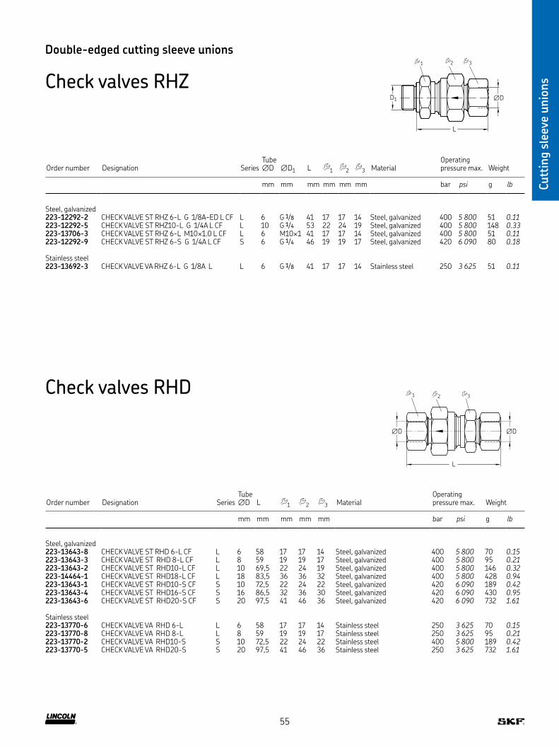
Cutt
ing s
leev
e unio
ns
Double-edged cutting sleeve unions
Check valves RHZ
L
1
2
D1 ∅D
3
Order number Designation SeriesTube ∅D ∅D1 L 1 2 3 Material
Operating pressure max Weight
mm mm mm mm mm mm bar psi g lb
Steel, galvanized223-12292-2 CHECK VALVE ST RHZ 6-L G 1/8A-ED L CF L 6 G 1/8 41 17 17 14 Steel, galvanized 400 5 800 51 0.11223-12292-5 CHECK VALVE ST RHZ10-L G 1/4A L CF L 10 G 1/4 53 22 24 19 Steel, galvanized 400 5 800 148 0.33223-13706-3 CHECK VALVE ST RHZ 6-L M10×1 0 L CF L 6 M10×1 41 17 17 14 Steel, galvanized 400 5 800 51 0.11223-12292-9 CHECK VALVE ST RHZ 6-S G 1/4A L CF S 6 G 1/4 46 19 19 17 Steel, galvanized 420 6 090 80 0.18
Stainless steel223-13692-3 CHECK VALVE VA RHZ 6-L G 1/8A L L 6 G 1/8 41 17 17 14 Stainless steel 250 3 625 51 0.11
Check valves RHD
∅D ∅D
L
1
2
3
Order number Designation SeriesTube ∅D L 1 2 3 Material
Operating pressure max Weight
mm mm mm mm mm bar psi g lb
Steel, galvanized223-13643-8 CHECK VALVE ST RHD 6-L CF L 6 58 17 17 14 Steel, galvanized 400 5 800 70 0.15223-13643-3 CHECK VALVE ST RHD 8-L CF L 8 59 19 19 17 Steel, galvanized 400 5 800 95 0.21223-13643-2 CHECK VALVE ST RHD10-L CF L 10 69,5 22 24 19 Steel, galvanized 400 5 800 146 0.32223-14464-1 CHECK VALVE ST RHD18-L CF L 18 83,5 36 36 32 Steel, galvanized 400 5 800 428 0.94223-13643-1 CHECK VALVE ST RHD10-S CF S 10 72,5 22 24 22 Steel, galvanized 420 6 090 189 0.42223-13643-4 CHECK VALVE ST RHD16-S CF S 16 86,5 32 36 30 Steel, galvanized 420 6 090 430 0.95223-13643-6 CHECK VALVE ST RHD20-S CF S 20 97,5 41 46 36 Steel, galvanized 420 6 090 732 1.61
Stainless steel223-13770-6 CHECK VALVE VA RHD 6-L L 6 58 17 17 14 Stainless steel 250 3 625 70 0.15223-13770-8 CHECK VALVE VA RHD 8-L L 8 59 19 19 17 Stainless steel 250 3 625 95 0.21223-13770-2 CHECK VALVE VA RHD10-S S 10 72,5 22 24 22 Stainless steel 400 5 800 189 0.42223-13770-5 CHECK VALVE VA RHD20-S S 20 97,5 41 46 36 Stainless steel 250 3 625 732 1.61
55

Cutt
ing s
leev
e unio
ns
Elbow bulkhead connectors WSV
∅D
16
∅D1
∅D
L2
L1
1
2
3
Double-edged cutting sleeve unions
Straight bulkhead connectors SV 16
∅D ∅D1 ∅D
1
2 3
L2L1
Order number Designation SeriesTube ∅D ∅D1 L1 L2 1 2 3 Material
Operating pressure max Weight
mm mm mm mm mm mm mm bar psi g lb
Steel, galvanized223-12368-4 Fitting ST SV 6-L CF L 6 12,5 22 42 17 17 14 Steel, galvanized 500 7 250 63 0.14223-12368-6 Fitting ST SV 8-L CF L 8 14,5 23 42 19 19 17 Steel, galvanized 500 7 250 84 0.19223-12368-8 Fitting ST SV 10-L CF L 10 16,5 25 43 22 22 19 Steel, galvanized 500 7 250 109 0.24223-13698-4 Fitting ST SV 12-L CF L 12 18,5 25 44 24 24 22 Steel, galvanized 400 5 800 134 0.30223-12564-2 Fitting ST SV 15-L CF L 15 22,5 27 46 27 30 27 Steel, galvanized 400 5 800 222 0.49223-12564-8 Fitting ST SV 18-L CF L 18 26,5 30 49 32 36 32 Steel, galvanized 400 5 800 334 0.74422-416 Fitting ST SV 22-L CF L 22 30,5 33 51 36 41 36 Steel, galvanized 250 3 625 432 0.95223-12364-6 Fitting ST SV 10-S CF S 10 18,5 31 46 24 24 22 Steel, galvanized 800 11 600 180 0.40223-12368-2 Fitting ST SV 20-S CF S 20 30,5 39 55 41 41 36 Steel, galvanized 420 6 090 688 1.52
Stainless steel223-13671-9 Fitting VA SV 8-S S 8 16,5 28 44 22 22 19 Stainless steel 630 9 140 133 0.29223-12564-3 Fitting VA SV 10-S S 10 18,5 31 46 24 24 22 Stainless steel 630 9 140 180 0.40223-13671-2 Fitting VA SV 20-S S 20 30,5 39 55 41 41 36 Stainless steel 400 5 800 688 1.52
Order number Designation SeriesTube ∅D ∅D1 L1 L2 1 2 3 Material
Operating pressure max Weight
mm mm mm mm mm mm mm bar psi g lb
Steel, galvanized223-13050-4 FITTING ST WSV 6-L CF L 6 12,5 48 27 12 17 14 Steel, galvanized 315 4 570 75 0.17223-12409-6 FITTING ST WSV 8-L CF L 8 14,5 51 29 12 19 17 Steel, galvanized 315 4 570 95 0.21223-12409-9 FITTING ST WSV 10-L CF L 10 16,5 53 30 14 22 19 Steel, galvanized 315 4 570 120 0.26412-409 FITTING ST WSV 12-L CF L 12 18,5 56 32 17 24 22 Steel, galvanized 315 4 570 141 0.31223-12409-8 FITTING ST WSV 15-L CF L 15 22,5 61 36 19 30 27 Steel, galvanized 315 4 570 184 0.41418-409 FITTING ST WSV 18-L CF L 18 26,5 64 40 24 36 32 Steel, galvanized 315 4 570 374 0.82223-13050-3 FITTING ST WSV 22-L CF L 22 30,5 72 44 27 41 36 Steel, galvanized 160 2 320 505 1.11223-13050-2 FITTING ST WSV 10-S CF S 10 18,5 57 34 17 24 22 Steel, galvanized 630 9 140 196 0.43223-12409-2 FITTING ST WSV 20-S CF S 20 30,5 74 48 27 41 36 Steel, galvanized 400 5 800 616 1.36
Stainless steel223-10364-6 FITTING VA WSV 8-S S 8 16,5 54 32 14 22 19 Stainless steel 630 9 140 155 0.34223-10364-3 FITTING VA WSV 10-S S 10 18,5 57 34 17 24 22 Stainless steel 630 9 140 196 0.43223-13758-4 FITTING VA WSV 20-S S 20 30,5 74 48 27 41 36 Stainless steel 400 5 800 616 1.36
Max wall thickness
Max wall thickness
56
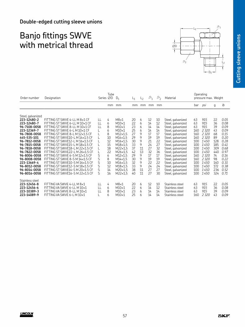
Cutt
ing s
leev
e unio
ns
Double-edged cutting sleeve unions
Banjo fittings SWVE with metrical thread
D1
∅D
1
2
L1
L2
Order number Designation SeriesTube ∅D D1 L1 L2 1 2 Material
Operating pressure max Weight
mm mm mm mm mm mm bar psi g lb
Steel, galvanized223-12480-2 FITTING ST SWVE 4-LL M 8×1 CF LL 4 M8×1 20 6 12 10 Steel, galvanized 63 915 22 0.05223-12480-7 FITTING ST SWVE 6-LL M 10×1 CF LL 6 M10×1 22 6 14 12 Steel, galvanized 63 915 36 0.0896-7108-0058 FITTING ST SWVE 8-LL M 10×1 CF LL 8 M10×1 23 6 14 14 Steel, galvanized 63 915 39 0.09223-12369-7 FITTING ST SWVE 6-L M 10×1 CF L 6 M10×1 25 6 14 14 Steel, galvanized 160 2 320 43 0.0996-7808-0058 FITTING ST SWVE 8-L M 12×1 5 CF L 8 M12×1,5 27 9 17 17 Steel, galvanized 160 2 320 68 0.15445-535-101 FITTING ST SWVE10-L M 14×1 5 CF L 10 M14×1,5 29 9 19 19 Steel, galvanized 160 2 320 89 0.2096-7812-0058 FITTING ST SWVE12-L M 16×1 5 CF L 12 M16×1,5 30 9 21 22 Steel, galvanized 100 1 450 128 0.2896-7815-0058 FITTING ST SWVE15-L M 18×1 5 CF L 15 M18×1,5 33 9 24 27 Steel, galvanized 100 1 450 185 0.4196-7818-0058 FITTING ST SWVE18-L M 22×1 5 CF L 18 M22×1,5 37 11 27 32 Steel, galvanized 100 1 450 309 0.6896-7822-0058 FITTING ST SWVE22-L M 26×1 5 CF L 22 M26×1,5 42 13 32 36 Steel, galvanized 100 1 450 440 0.9796-8006-0058 FITTING ST SWVE 6-S M 12×1 5 CF S 6 M12×1,5 29 9 17 17 Steel, galvanized 160 2 320 74 0.1696-8008-0058 FITTING ST SWVE 8-S M 14×1 5 CF S 8 M14×1,5 30 9 19 19 Steel, galvanized 160 2 320 98 0.22223-13669-4 FITTING ST SWVE10-S M 16×1 5 CF S 10 M16×1,5 32 9 22 22 Steel, galvanized 100 1 450 140 0.3196-8012-0058 FITTING ST SWVE12-S M 18×1 5 CF S 12 M18×1,5 33 9 24 24 Steel, galvanized 100 1 450 172 0.3896-8014-0058 FITTING ST SWVE14-S M 20×1 5 CF S 14 M20×1,5 38 11 27 27 Steel, galvanized 100 1 450 236 0.5296-8016-0058 FITTING ST SWVE16-S M 22×1 5 CF S 16 M22×1,5 40 11 27 30 Steel, galvanized 100 1 450 324 0.71
Stainless steel223-12456-8 FITTING VA SWVE 4-LL M 8×1 LL 4 M8×1 20 6 12 10 Stainless steel 63 915 22 0.05223-12456-6 FITTING VA SWVE 6-LL M 10×1 LL 6 M10×1 22 6 14 12 Stainless steel 63 915 36 0.08223-10389-3 FITTING VA SWVE 8-LL M 10×1 LL 8 M10×1 23 6 14 14 Stainless steel 63 915 39 0.09223-14089-9 FITTING VA SWVE 6-L M 10×1 L 6 M10×1 25 6 14 14 Stainless steel 160 2 320 43 0.09
57

Cutt
ing s
leev
e unio
ns
Banjo fittings WH (high-pressure)
Double-edged cutting sleeve unions
Banjo fittings SWVE with Whitworth pipe thread
D1
∅D
1
2
L1
L2
Order number Designation SeriesTube ∅D D1 L1 L2 1 2 Material
Operating pressure max Weight
mm mm mm mm mm mm bar psi g lb
Steel, galvanized223-13629-1 FITTING ST SWVE 4-LL G1/8 CF LL 4 G 1/8 21 6 14 10 Steel, galvanized 63 915 32 0.07223-12479-9 FITTING ST SWVE 6-LL G1/8 CF LL 6 G 1/8 22 6 14 12 Steel, galvanized 63 915 35 0.08223-12479-8 FITTING ST SWVE 8-LL G1/8 CF LL 8 G 1/8 23 6 14 14 Steel, galvanized 63 915 38 0.08223-12479-5 FITTING ST SWVE 6-L G1/8 CF L 6 G 1/8 25 6 14 14 Steel, galvanized 160 2 320 43 0.09223-12284-7 FITTING ST SWVE 8-L G1/4 CF L 8 G 1/4 28 9 19 17 Steel, galvanized 160 2 320 82 0.18223-12369-9 FITTING ST SWVE 10-L G1/4 CF L 10 G 1/4 29 9 19 22 Steel, galvanized 160 2 320 87 0.19223-13669-3 FITTING ST SWVE 12-L G3/8 CF L 12 G 3/8 30 9 19 22 Steel, galvanized 100 1 450 130 0.29445-513-181 FITTING ST SWVE 18-L G1/2 CF L 18 G 1/2 37 11 27 32 Steel, galvanized 100 1 450 317 0.70445-517-222 FITTING ST SWVE 22-L G3/4 CF L 22 G 3/4 42 13 32 36 Steel, galvanized 100 1 450 438 0.97223-12285-8 FITTING ST SWVE 6-S G1/4 CF S 6 G 1/4 30 9 19 17 Steel, galvanized 160 2 320 88 0.19223-12285-9 FITTING ST SWVE 8-S G1/4 CF S 8 G 1/4 30 9 19 19 Steel, galvanized 160 2 320 96 0.21223-12285-5 FITTING ST SWVE 10-S G3/8 CF S 10 G 3/8 32 9 22 22 Steel, galvanized 100 1 450 142 0.31223-12285-6 FITTING ST SWVE 12-S G3/8 CF S 12 G 3/8 33 9 24 24 Steel, galvanized 100 1 450 185 0.4196-7914-0058 FITTING ST SWVE 14-S G1/2 CF S 14 G 1/2 38 11 27 27 Steel, galvanized 100 1 450 234 0.5296-7916-0058 FITTING ST SWVE 16-S G1/2 CF S 16 G 1/2 40 11 27 30 Steel, galvanized 100 1 450 321 0.71223-12285-7 FITTING ST SWVE 20-S G3/4 CF S 20 G 3/4 46 13 32 36 Steel, galvanized 100 1 450 472 1.04
Stainless steel223-12456-7 FITTING VA SWVE 6-LL G1/8 LL 6 G 1/8 22 6 14 12 Stainless steel 63 915 35 0.08223-10389-4 FITTING VA SWVE 6-S G1/4 L 6 G 1/4 22 9 19 17 Stainless steel 160 2 320 45 0.10223-12456-9 FITTING VA SWVE 8-L G1/4 L 8 G 1/4 28 9 19 17 Stainless steel 160 2 320 82 0.18223-12456-1 FITTING VA SWVE 10-L G1/4 L 10 G 1/4 29 9 19 22 Stainless steel 160 2 320 87 0.19223-14089-5 FITTING VA SWVE 12-L G3/8 L 12 G 3/8 30 9 19 22 Stainless steel 100 1 450 130 0.29223-14089-6 FITTING VA SWVE 16-S G1/2 S 16 G 1/2 40 11 27 30 Stainless steel 100 1 450 321 0.71
D1
∅D
1
2
L1
L2
Order number Designation SeriesTube ∅D D1 L1 L2 1 2 Material
Operating pressure max Weight
mm mm mm mm mm mm bar psi g lb
Steel, galvanized223-13679-8 FITTING ST WH10-L G1/4A-KD CF L 10 G 1/4 30 12 19 19 Steel, galvanized 315 4 570 123 0.27223-13679-3 FITTING ST WH10-S G3/8A-KD CF S 10 G 3/8 35 12 24 22 Steel, galvanized 400 5 800 212 0.47223-13679-9 FITTING ST WH10-S M16×1 5-KD CF S 10 M16×1,5 35 12 24 22 Steel, galvanized 315 4 570 220 0.49
Stainless steel223-14238-4 FITTING VA WH10-L G1/4 L 10 G 1/4 30 12 19 19 Stainless steel 315 4 570 123 0.27
58
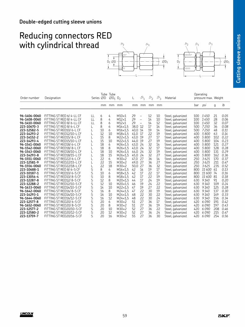
Cutt
ing s
leev
e unio
ns
Double-edged cutting sleeve unions
Reducing connectors RED with cylindrical thread
∅DD2 ∅D1 ∅D1
2
3
1 2
3
LL
D2
Order number Designation SeriesTube ∅D
Tube ∅D1 D2 L 1 2 3 Material
Operating pressure max Weight
mm mm mm mm mm mm mm bar psi g lb
96-1406-0060 FITTING ST RED 6/ 4-LL CF LL 6 4 M10×1 29 – 12 10 Steel, galvanized 100 1 450 21 0.0596-1408-0060 FITTING ST RED 8/ 4-LL CF LL 8 4 M12×1 29 – 14 10 Steel, galvanized 100 1 450 28 0.0696-1410-0060 FITTING ST RED 8/ 6-LL CF LL 8 6 M12×1 29 – 14 12 Steel, galvanized 100 1 450 32 0.07223-10670-3 FITTING ST RED 8/ 6-L CF L 8 6 M14×1,5 38,0 12 17 14 Steel, galvanized 500 7 250 36 0.08223-12582-5 FITTING ST RED10/ 6-L CF L 10 6 M16×1,5 40,0 14 19 14 Steel, galvanized 500 7 250 48 0.11223-14293-2 FITTING ST RED12/10-L CF L 12 10 M18×1,5 41,0 17 22 19 Steel, galvanized 400 5 800 63 0.14223-14152-2 FITTING ST RED15/ 8-L CF L 15 8 M22×1,5 43,0 19 27 17 Steel, galvanized 400 5 800 102 0.22223-14293-4 FITTING ST RED15/10-L CF L 15 10 M22×1,5 44,0 19 27 19 Steel, galvanized 400 5 800 104 0.2396-1541-0060 FITTING ST RED18/ 6-L CF L 18 6 M26×1,5 43,0 24 32 14 Steel, galvanized 400 5 800 121 0.2796-1542-0060 FITTING ST RED18/ 8-L CF L 18 8 M26×1,5 43,0 24 32 17 Steel, galvanized 400 5 800 128 0.2896-1543-0060 FITTING ST RED18/10-L CF L 18 10 M26×1,5 44,0 24 32 19 Steel, galvanized 400 5 800 131 0.29223-14293-8 FITTING ST RED18/15-L CF L 18 15 M26×1,5 45,0 24 32 27 Steel, galvanized 400 5 800 162 0.3696-1551-0060 FITTING ST RED22/ 6-L CF L 22 6 M30×2 47,0 27 36 14 Steel, galvanized 250 3 625 170 0.37223-12581-9 FITTING ST RED22/15-L CF L 22 15 M30×2 49,0 27 36 27 Steel, galvanized 250 3 625 211 0.4796-1556-0060 FITTING ST RED22/18-L CF L 22 18 M30×2 50,0 27 36 32 Steel, galvanized 250 3 625 235 0.52223-10688-1 FITTING ST RED 8/ 6-S CF S 8 6 M16×1,5 42 14 19 17 Steel, galvanized 800 11 600 61 0.13223-10187-1 FITTING ST RED10/ 6-S CF S 10 6 M18×1,5 42 17 22 17 Steel, galvanized 800 11 600 74 0.16223-13054-4 FITTING ST RED10/ 8-S CF S 10 8 M18×1,5 42 17 22 19 Steel, galvanized 800 11 600 81 0.18223-12287-8 FITTING ST RED12/ 8-S CF S 12 8 M20×1,5 44 17 24 19 Steel, galvanized 630 9 140 91 0.20223-12288-2 FITTING ST RED12/10-S CF S 12 10 M20×1,5 46 19 24 22 Steel, galvanized 630 9 140 109 0.2496-1633-0060 FITTING ST RED14/10-S CF S 14 10 M22×1,5 47 19 27 22 Steel, galvanized 630 9 140 125 0.2896-1642-0060 FITTING ST RED16/ 8-S CF S 16 8 M24×1,5 47 22 30 19 Steel, galvanized 630 9 140 137 0.30223-14293-1 FITTING ST RED16/10-S CF S 16 10 M24×1,5 48 22 30 22 Steel, galvanized 630 9 140 149 0.3396-1644-0060 FITTING ST RED16/12-S CF S 16 12 M24×1,5 48 22 30 24 Steel, galvanized 630 9 140 156 0.34223-12577-8 FITTING ST RED20/ 6-S CF S 20 6 M30×2 51 27 36 17 Steel, galvanized 420 6 090 191 0.4296-1652-0060 FITTING ST RED20/ 8-S CF S 20 8 M30×2 51 27 36 19 Steel, galvanized 420 6 090 197 0.43223-12577-2 FITTING ST RED20/10-S CF S 20 10 M30×2 52 27 36 22 Steel, galvanized 420 6 090 208 0.46223-12580-2 FITTING ST RED20/12-S CF S 20 12 M30×2 52 27 36 24 Steel, galvanized 420 6 090 215 0.47223-13759-7 FITTING ST RED20/16-S CF S 20 16 M30×2 55 27 36 30 Steel, galvanized 420 6 090 254 0.56
59

Cutt
ing s
leev
e unio
ns
Order number Designation SeriesTube ∅D D1 L 1 2 Material
Operating pressure max Weight
mm mm mm mm mm bar psi g lb
Steel, galvanized223-12481-4 FITTING ST MAV 6-L G 1/4 CF L 6 G 1/4 37 19 14 Steel, galvanized 315 4 570 49 0.11223-12481-6 FITTING ST MAV 8-L G 1/4 CF L 8 G 1/4 37 19 17 Steel, galvanized 315 4 570 55 0.12223-13028-2 FITTING ST MAV10-L G 1/4 CF L 10 G 1/4 38 19 19 Steel, galvanized 315 4 570 62 0.14223-12481-8 FITTING ST MAV12-L G 1/4 CF L 12 G 1/4 38 19 22 Steel, galvanized 315 4 570 71 0.16441-108-132 FITTING ST MAV 8-S G 1/2 CF S 8 G 1/2 46 27 19 Steel, galvanized 630 9 140 105 0.23223-13028-4 FITTING ST MAV10-S G 1/2 CF S 10 G 1/2 47 27 22 Steel, galvanized 630 9 140 111 0.24223-12286-8 FITTING ST MAV12-S G 1/2 CF S 12 G 1/2 47 27 24 Steel, galvanized 630 9 140 131 0.29
Stainless steel223-13685-3 FITTING VA MAV 6-L G 1/4 CF L 6 G 1/4 37 19 14 Stainless steel 315 4 570 49 0.11223-13685-1 FITTING VA MAV10-S G 1/2 CF S 10 G 1/2 47 27 22 Stainless steel 630 9 140 111 0.24
Double-edged cutting sleeve unions
Connectors for pressure gauges MAVD1
∅D
1
2
L
Connectors for pressure gauges MAVE(Swivel with O-ring)
∅D
D1
1
2
L
Order number Designation SeriesTube ∅D D1 L 1 2 Material
Operating pressure max Weight
mm mm mm mm mm bar psi g lb
Steel, galvanized96-8804-0058 FITTING ST MAVE 4-L G 1/4 CF L 4 G 1/4 33 19 10 Steel, galvanized 315 4 570 42 0.09223-13655-1 FITTING ST MAVE 6-L G 1/4 CF L 6 G 1/4 35,5 19 14 Steel, galvanized 315 4 570 46 0.10223-10889-2 FITTING ST MAVE 8-L G 1/4 CF L 8 G 1/4 35,5 19 17 Steel, galvanized 315 4 570 52 0.11223-13655-7 FITTING ST MAVE 10-L G 1/4 CF L 10 G 1/4 36,0 19 19 Steel, galvanized 315 4 570 59 0.13223-14268-4 FITTING ST MAVE 12-L G 1/4 CF L 12 G 1/4 36,0 19 22 Steel, galvanized 315 4 570 70 0.1596-8906-0058 FITTING ST MAVE 6-S G 1/2 CF S 6 G 1/2 42,5 27 17 Steel, galvanized 630 9 140 95 0.21223-13655-2 FITTING ST MAVE 10-S G 1/2 CF S 10 G 1/2 43,5 27 22 Steel, galvanized 630 9 140 109 0.24223-13655-4 FITTING ST MAVE 12-S G 1/2 CF S 12 G 1/2 45,0 27 24 Steel, galvanized 630 9 140 125 0.28
Stainless steel223-14268-7 FITTING AV MAVE 6-L G 1/4 CF L 6 G 1/4 35,5 19 14 Stainless steel 315 4 570 46 0.10223-13655-5 FITTING AV MAVE 10-S G 1/2 CF S 10 G 1/2 43,5 27 22 Stainless steel 630 9 140 109 0.24
60

Cutt
ing s
leev
e unio
ns
Double-edged cutting sleeve unions
L-connectors EL, EVL directionally adjustable
∅D
D1
∅D
1
2
L
L
Order number Designation SeriesTube ∅D ∅D1 L 1 2 Material
Operating pressure max Weight
mm mm mm mm mm bar psi g lb
Steel, galvanized223-14190-6 STUD ST EL 6-L CF L 6 M12×1,5 27 12 14 Steel, galvanized 500 7 250 68 0.15223-14190-7 STUD ST EL 8-L CF L 8 M14×1,5 29 12 17 Steel, galvanized 500 7 250 87 0.19223-13040-9 STUD ST EL 10-L CF L 10 M16×1,5 30 14 19 Steel, galvanized 500 7 250 110 0.24223-13761-5 STUD ST EL 12-L CF L 12 M18×1,5 32 17 22 Steel, galvanized 400 5 800 151 0.33223-14190-5 STUD ST EL 15-L CF L 15 M22×1,5 36 19 27 Steel, galvanized 400 5 800 245 0.54443-418-181 STUD ST EL 18-L CF L 18 M26×1,5 40 24 32 Steel, galvanized 400 5 800 369 0.81223-13040-3 STUD ST EL 6-S CF S 6 M14×1,5 31 12 17 Steel, galvanized 800 11 600 103 0.23223-13040-7 STUD ST EL 8-S CF S 8 M16×1,5 32 14 19 Steel, galvanized 800 11 600 130 0.29223-14190-2 STUD ST EL 10-S CF S 10 M18×1,5 34 17 22 Steel, galvanized 800 11 600 136 0.30223-14190-4 STUD ST EL 12-S CF S 12 M20×1,5 38 17 24 Steel, galvanized 630 9 140 212 0.47223-14190-1 STUD ST EL 16-S CF S 16 M24×1,5 43 24 30 Steel, galvanized 630 9 140 404 0.89223-13761-7 STUD ST EL 20-S CF S 20 M30×2 48 27 36 Steel, galvanized 420 6 090 601 1.33443-410-211 FITTING ST EVL 10-S G3/8A CF S 10 G 3/8 34 17 22 Steel, galvanized 630 9 140 226 0.50443-410-161 FITTING ST EVL 10-L G1/4A CF L 10 G 1/4 30 14 19 Steel, galvanized 250 3 625 132 0.29
Stainless steel223-14244-8 STUD VA EL 10-L L 10 M16×1,5 30 14 19 Stainless steel 315 4 570 110 0.24223-14244-6 STUD VA EL 20-S S 20 M30×2 48 27 36 Stainless steel 400 5 800 601 1.33
61
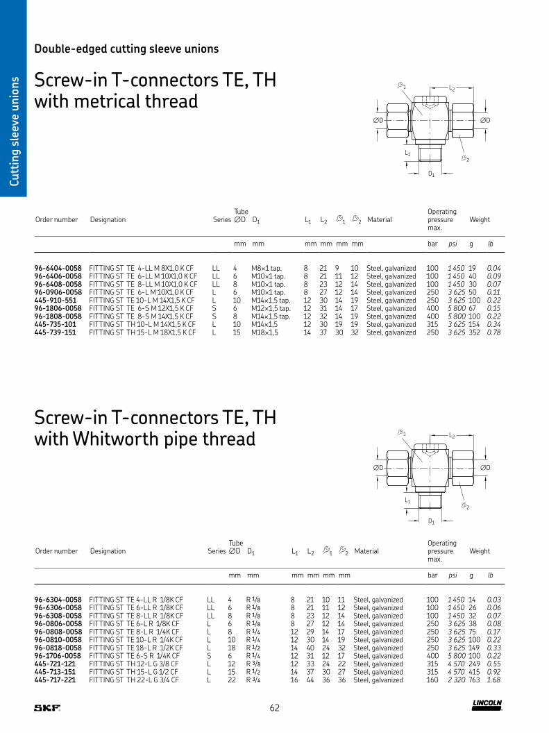
Cutt
ing s
leev
e unio
ns
Order number Designation SeriesTube ∅D D1 L1 L2 1 2 Material
Operating pressure max
Weight
mm mm mm mm mm mm bar psi g lb
96-6404-0058 FITTING ST TE 4-LL M 8X1,0 K CF LL 4 M8×1 tap 8 21 9 10 Steel, galvanized 100 1 450 19 0.0496-6406-0058 FITTING ST TE 6-LL M 10X1,0 K CF LL 6 M10×1 tap 8 21 11 12 Steel, galvanized 100 1 450 40 0.0996-6408-0058 FITTING ST TE 8-LL M 10X1,0 K CF LL 8 M10×1 tap 8 23 12 14 Steel, galvanized 100 1 450 30 0.0796-0906-0058 FITTING ST TE 6-L M 10X1,0 K CF L 6 M10×1 tap 8 27 12 14 Steel, galvanized 250 3 625 50 0.11445-910-551 FITTING ST TE 10-L M 14X1,5 K CF L 10 M14×1,5 tap 12 30 14 19 Steel, galvanized 250 3 625 100 0.2296-1806-0058 FITTING ST TE 6-S M 12X1,5 K CF S 6 M12×1,5 tap 12 31 14 17 Steel, galvanized 400 5 800 67 0.1596-1808-0058 FITTING ST TE 8-S M 14X1,5 K CF S 8 M14×1,5 tap 12 32 14 19 Steel, galvanized 400 5 800 100 0.22445-735-101 FITTING ST TH 10-L M 14X1,5 K CF L 10 M14×1,5 12 30 19 19 Steel, galvanized 315 3 625 154 0.34445-739-151 FITTING ST TH 15-L M 18X1,5 K CF L 15 M18×1,5 14 37 30 32 Steel, galvanized 250 3 625 352 0.78
Double-edged cutting sleeve unions
Screw-in T-connectors TE, TH with metrical thread
D1
∅D ∅D
L1
1
2
L2
Screw-in T-connectors TE, TH with Whitworth pipe thread
Order number Designation SeriesTube ∅D D1 L1 L2 1 2 Material
Operating pressure max
Weight
mm mm mm mm mm mm bar psi g lb
96-6304-0058 FITTING ST TE 4-LL R 1/8K CF LL 4 R 1/8 8 21 10 11 Steel, galvanized 100 1 450 14 0.0396-6306-0058 FITTING ST TE 6-LL R 1/8K CF LL 6 R 1/8 8 21 11 12 Steel, galvanized 100 1 450 26 0.0696-6308-0058 FITTING ST TE 8-LL R 1/8K CF LL 8 R 1/8 8 23 12 14 Steel, galvanized 100 1 450 32 0.0796-0806-0058 FITTING ST TE 6-L R 1/8K CF L 6 R 1/8 8 27 12 14 Steel, galvanized 250 3 625 38 0.0896-0808-0058 FITTING ST TE 8-L R 1/4K CF L 8 R 1/4 12 29 14 17 Steel, galvanized 250 3 625 75 0.1796-0810-0058 FITTING ST TE 10-L R 1/4K CF L 10 R 1/4 12 30 14 19 Steel, galvanized 250 3 625 100 0.2296-0818-0058 FITTING ST TE 18-L R 1/2K CF L 18 R 1/2 14 40 24 32 Steel, galvanized 250 3 625 149 0.3396-1706-0058 FITTING ST TE 6-S R 1/4K CF S 6 R 1/4 12 31 12 17 Steel, galvanized 400 5 800 100 0.22445-721-121 FITTING ST TH 12-L G 3/8 CF L 12 R 3/8 12 33 24 22 Steel, galvanized 315 4 570 249 0.55445-713-151 FITTING ST TH 15-L G 1/2 CF L 15 R 1/2 14 37 30 27 Steel, galvanized 315 4 570 415 0.92445-717-221 FITTING ST TH 22-L G 3/4 CF L 22 R 3/4 16 44 36 36 Steel, galvanized 160 2 320 763 1.68
D1
∅D ∅D
L1
1
2
L2
62

Cutt
ing s
leev
e unio
ns
Double-edged cutting sleeve unions
Swivel nut branch ET
D1
∅D
L1 1
2
L2
Order number Designation SeriesTube ∅D D1 L1 L2 1 2 Material
Operating pressure max Weight
mm mm mm mm mm mm bar psi g lb
223-14189-6 STUD ST ET 6-L CF L 6 M12×1,5 27 26 12 14 Steel, galvanized 500 7 250 68 0.15223-13040-1 STUD ST ET 8-L CF L 8 M14×1,5 29 26,5 12 17 Steel, galvanized 500 7 250 87 0.19223-14189-1 STUD ST ET10-L CF L 10 M16×1,5 30 29 14 19 Steel, galvanized 500 7 250 113 0.25223-13785-8 STUD ST ET12-L CF L 12 M18×1,5 32 29,5 17 22 Steel, galvanized 400 5 800 153 0.34223-14189-7 STUD ST ET15-L CF L 15 M22×1,5 36 32,5 19 27 Steel, galvanized 400 5 800 253 0.5696-3118-0060 STUD ST ET18-L CF L 18 M26×1,5 40 35,5 24 32 Steel, galvanized 400 5 800 375 0.8396-3122-0060 STUD ST ET22-L CF L 22 M30×1,5 44 38,5 27 36 Steel, galvanized 250 3 625 486 1.07445-806-351 STUD ST ET 6-S CF S 6 M14×1,5 31 27 12 17 Steel, galvanized 800 11 600 101 0.22223-10374-3 STUD ST ET 8-S CF S 8 M16×1,5 32 27,5 14 19 Steel, galvanized 800 11 600 135 0.30223-14189-5 STUD ST ET10-S CF S 10 M18×1,5 34 30 17 22 Steel, galvanized 800 11 600 181 0.40223-14189-9 STUD ST ET12-S CF S 12 M20×1,5 38 31 17 24 Steel, galvanized 630 9 140 212 0.47223-14189-2 STUD ST ET16-S CF S 16 M24×1,5 43 36,5 24 30 Steel, galvanized 630 9 140 383 0.84223-14189-3 STUD ST ET20-S CF S 20 M30×1,5 48 44,5 27 36 Steel, galvanized 420 6 090 614 1.35
Swivel nut elbow EW
D1
∅D
L1 1
2
L2
Order number Designation SeriesTube ∅D D1 L1 L2 1 2 Material
Operating pressure max Weight
mm mm mm mm mm mm bar psi g lb
223-14171-1 STUD ST EW 6-L CF L 6 M12×1,5 27 26 12 14 Steel, galvanized 500 7 250 46 0.10223-14102-3 STUD ST EW 8-L CF L 8 M14×1,5 29 27,5 12 17 Steel, galvanized 500 7 250 59 0.13443-306-343 STUD ST EW 6-S CF S 6 M14×1,5 31 27 12 17 Steel, galvanized 800 11 600 67 0.15223-14171-8 STUD ST EW10-S CF S 10 M18×1,5 34 30 17 22 Steel, galvanized 800 11 600 126 0.28223-14171-4 STUD ST EW16-S CF S 16 M24×1,5 43 36,5 24 30 Steel, galvanized 630 9 140 284 0.63223-14171-5 STUD ST EW20-S CF S 20 M30×1,5 48 44,5 27 36 Steel, galvanized 420 6 090 422 0.93
63

Cutt
ing s
leev
e unio
ns
Double-edged cutting sleeve unions
Swivels DVWE
Order number Designation Tube ∅ ∅ D1 SeriesSpeed max
Operation pressure max Material Weight
mm in min-1 bar psi g lb
Steel galvanized223-13694-6 Fitting DVWE10-L G 3/8A CF 10 G 3/8 L 21 40 580 Steel galvanized 83 0.18223-13694-1 Fitting DVWE10-S G 3/8A CF 10 G 3/8 S 9 100 1 450 Steel galvanized 103 0.23
Stainless steel223-13694-7 Fitting DVWE10-L G 3/8A 10 G 3/8 L 21 40 580 Stainless steel 83 0.18223-13694-3 Fitting DVWE10-S G 3/8A 10 G 3/8 S 9 100 1 450 Stainless steel 103 0.23
Order number Designation Tube ∅ ∅ D1 SeriesSpeed max
Operation pressure max Material Weight
mm in min-1 bar psi g lb
223-13655-7 Fitting DG104/ 6-S G 1/4A CF 6 G 1/4 S 400 100 1 450 Steel galvanized 131 0.29223-13655-8 Fitting DG104/ 8-S G 1/4A CF 8 G 1/4 S 400 100 1 450 Steel galvanized 135 0.30223-13655-9 Fitting DG104/12-S G 3/8A CF 12 G 3/8 S 200 100 1 450 Steel galvanized 284 0.62
L3
L4
∅D3
L2L1
∅D1
21
L3L5
∅D3
L2
L1
∅D12
1
L6
Swivels DG
64

Cutt
ing s
leev
e unio
ns
Double-edged cutting sleeve unions
Blanking plug for cones BUZ
Order number DesignationSeries
D L MaterialOperating pressure max Weight
mm mm bar psi g lb
Steel galvanized223-13640-1 PLUG ST BUZ 6-L/S CF L/S 6 19,5 Steel, galvanized 315 4 570 5 0.01223-13640-5 PLUG ST BUZ 8-L/S CF L/S 8 19,5 Steel, galvanized 315 4 570 8 0.02223-13640-3 PLUG ST BUZ10 -L/S CF L/S 10 21,0 Steel, galvanized 315 4 570 13 0.03223-13640-4 PLUG ST BUZ12 -L/S CF L/S 12 21,8 Steel, galvanized 315 4 570 20 0.04223-13640-9 PLUG ST BUZ18 -L CF L/S 18 24,0 Steel, galvanized 315 4 570 45 0.10223-13640-8 PLUG ST BUZ16 -S CF S 16 25,5 Steel, galvanized 400 5 800 39 0.09223-13640-2 PLUG ST BUZ20 -S CF S 20 30,5 Steel, galvanized 400 5 800 73 0.16
Stainless steel223-14215-5 PLUG VA BUZ 6-L/S L/S 6 19,5 Stainless steel 315 4 570 5 0.01223-14215-3 PLUG VA BUZ10 -L/S L/S 10 21,0 Stainless steel 315 4 570 13 0.03223-14215-2 PLUG VA BUZ12 -L/S L/S 12 21,8 Stainless steel 315 4 570 20 0.04223-10638-3 PLUG VA BUZ16 -S S 16 25,5 Stainless steel 400 5 800 39 0.09223-14215-4 PLUG VA BUZ20 -S S 20 30,5 Stainless steel 400 5 800 73 0.16
D
L
65
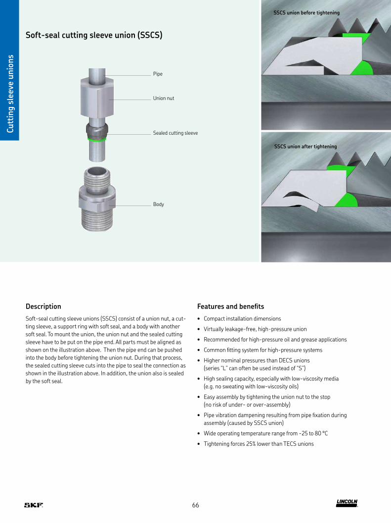
Soft-seal cutting sleeve union (SSCS)
Sealed cutting sleeve
Union nut
Pipe
Body
Cutt
ing s
leev
e unio
ns
Description
Soft-seal cutting sleeve unions (SSCS) consist of a union nut, a cut-
ting sleeve, a support ring with soft seal, and a body with another
soft seal To mount the union, the union nut and the sealed cutting
sleeve have to be put on the pipe end All parts must be aligned as
shown on the illustration above Then the pipe end can be pushed
into the body before tightening the union nut During that process,
the sealed cutting sleeve cuts into the pipe to seal the connection as
shown in the illustration above In addition, the union also is sealed
by the soft seal
Features and benefits
• Compact installation dimensions
• Virtually leakage-free, high-pressure union
• Recommended for high-pressure oil and grease applications
• Common fitting system for high-pressure systems
• Higher nominal pressures than DECS unions
(series “L” can often be used instead of “S”)
• High sealing capacity, especially with low-viscosity media
(e g no sweating with low-viscosity oils)
• Easy assembly by tightening the union nut to the stop
(no risk of under- or over-assembly)
• Pipe vibration dampening resulting from pipe fixation during
assembly (caused by SSCS union)
• Wide operating temperature range from -25 to 80 °C
• Tightening forces 25% lower than TECS unions
SSCS union before tightening
SSCS union after tightening
66

Cutt
ing s
leev
e unio
ns
Soft-seal cutting sleeve union
Straight screw-in connectors GEZ
DD1
L1
Order number Designation SeriesTube ∅D ∅D1 L L 1 1 2 Material
Operating pressure max Weight
mm mm mm mm mm bar psi g lb
471-004-191 FITTING ST GE 4Z-LL G 1/8A ED CF LL 4 G 1/8 19 6,5 14 10 Steel galvanized 100 1 450 15 0.03471-004-311 FITTING ST GE 4Z-LL M 10X1,0 ED CF LL 4 M10x1 26 8 10 10 Steel galvanized 100 1 450 15 0.03471-006-192 FITTING ST GE 6Z-L G 1/8A ED CF L 6 G 1/8 23 8 14 14 Steel galvanized 500 7 250 25 0.06471-006-161 FITTING ST GE 6Z-L G 1/4A ED CF L 6 G 1/4 25 12 19 14 Steel galvanized 500 7 250 40 0.09471-006-311 FITTING ST GE 6Z-L M 10X1,0 ED CF L 6 M10x1 23 8 14 14 Steel galvanized 500 7 250 25 0.06471-006-351 FITTING ST GE 6Z-L M 14X1,5 ED CF L 6 M14x1,5 27 12 14 14 Steel galvanized 400 5 800 44 0.10471-008-130 FITTING ST GE 8Z-L G 1/8A ED CF L 8 G 1/8 24 8 14 17 Steel galvanized 500 7 250 33 0.07471-008-161 FITTING ST GE 8Z-L G 1/4A ED CF L 8 G 1/4 25 12 19 17 Steel galvanized 500 7 250 44 0.10471-008-131 FITTING ST GE 8Z-L G 1/2A ED CF L 8 G 1/2 27 14 27 17 Steel galvanized 400 5 800 90 0.20471-008-211 FITTING ST GE 8Z-L G 3/8A ED CF L 8 G 3/8 26 12 22 17 Steel galvanized 400 5 800 60 0.13471-008-314 FITTING ST GE 8Z-L M 10X1,0 ED CF L 8 M 10x1 34 7 17 14 Steel galvanized 45 650 40 0.09471-008-345 FITTING ST GE 8Z-L M 12X1,5 ED CF L 8 M12x1,5 25 12 17 17 Steel galvanized 500 7 250 37 0.08471-008-351 FITTING ST GE 8Z-S M 14X1,5 ED CF S 8 M14x1,5 30 12 19 19 Steel galvanized 400 5 800 50 0.11471-008-391 FITTING ST GE 8Z-L M 18X1,5 ED CF L 8 M18x1,5 38 11 24 17 Steel galvanized 400 5 800 70 0.15471-010-161 FITTING ST GE 10Z-L G 1/4A ED CF L 10 G 1/4 26 12 19 19 Steel galvanized 500 7 250 50 0.11471-010-211 FITTING ST GE 10Z-L G 3/8A ED CF L 10 G 3/8 27 12 22 22 Steel galvanized 400 5 800 60 0.13471-010-312 FITTING ST GE 10Z-L M 10X1,0 ED CF L 10 M10x1 32 8 19 17 Steel galvanized 500 7 250 43 0.09471-010-351 FITTING ST GE 10Z-L M 14X1,5 ED CF L 10 M14x1,5 26 12 19 19 Steel galvanized 500 7 250 50 0.11471-010-391 FITTING ST GE 10Z-L M 18X1,5 ED CF L 10 M18x1,5 27 12 24 19 Steel galvanized 400 5 800 75 0.17471-012-161 FITTING ST GE 12Z-L G 1/4A ED CF L 12 G 1/4 27 12 19 22 Steel galvanized 400 5 800 58 0.13471-012-211 FITTING ST GE 12Z-L G 3/8A ED CF L 12 G 3/8 27 12 22 22 Steel galvanized 400 5 800 73 0.16471-012-391 FITTING ST GE 12Z-L M 18X1,5 ED CF L 12 M18x1,5 27 12 24 22 Steel galvanized 400 5 800 120 0.26
67

Cutt
ing s
leev
e unio
ns
Soft-seal cutting sleeve union
Straight screw-in connectors with shortened thread and function nut GEZ (short)
Order number Designation SeriesTube ∅D ∅D1 L1 1 2 Material
Operating pressure max
Weight
mm mm mm mm mm bar psi g lb
471-006-320 TB FITT ST GE 6Z-LL M 10x1,0 ED CF (SHORT) LL 6 M10x1 31 14 14 Steel galvanized 100 1 450 27 0.06471-006-319 TB FITT ST GE 6Z-LL M 12x1,0 ED CF (SHORT) LL 6 M12x1 31 14 19 Steel galvanized 100 1 450 40 0.09471-008-312 TB FITT ST GE 8Z-LL M 10x1,0 ED CF (SHORT) LL 8 M10x1 34 17 14 Steel galvanized 100 1 450 35 0.08471-008-318 TB FITT ST GE 8Z-LL M 12x1,0 ED CF (SHORT) LL 8 M12x1 32 17 19 Steel galvanized 100 1 450 70 0.15471-010-312 TB FITT ST GE 10Z-LL M 10x1,0 ED CF (SHORT) LL 10 M10x1 32 19 17 Steel galvanized 100 1 450 43 0.09471-010-318 TB FITT ST GE 10Z-LL M 12x1,0 ED CF (SHORT) LL 10 M12x1 34 19 19 Steel galvanized 100 1 450 45 0.10471-012-312 TB FITT ST GE 12Z-LL M 10x1,0 ED CF (SHORT) LL 12 M10x1 36 22 22 Steel galvanized 100 1 450 57 0.13417-012-313 TB FITT ST GE 12Z-LL M 12x1,0 ED CF (SHORT) LL 12 M12x1 34 22 22 Steel galvanized 100 1 450 51 0.11
Straight bulkhead connectors with function nut SVZ
max. 16
D DD1
Order number Designation SeriesTube ∅D D1 L 1 L 2 1 2 3 Material
Operating pressure max Weight
mm mm mm mm mm mm mm bar psi g lb
474-606-331 FITTING ST SV 6Z-L CF L 6 12,5 22 42 17 17 14 Steel galvanized 500 7 250 61 0.13474-608-351 FITTING ST SV 8Z-L CF L 8 14,5 23 42 19 19 17 Steel galvanized 500 7 250 83 0.18474-610-351 FITTING ST SV10Z-L CF L 10 16,5 25 43 22 22 19 Steel galvanized 500 7 250 100 0.22474-612-391 FITTING ST SV12Z-L CF L 12 18,5 25 44 24 24 22 Steel galvanized 400 5 800 134 0.30474-615-431 FITTING ST SV15Z-L CF L 15 22,5 27 46 27 30 27 Steel galvanized 400 5 800 224 0.49474-618-441 FITTING ST SV18Z-L CF L 18 26,5 30 49 32 36 32 Steel galvanized 400 5 800 344 0.76
DD1
L1
68
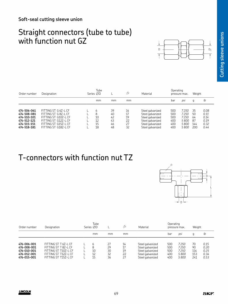
Cutt
ing s
leev
e unio
ns
Soft-seal cutting sleeve union
Straight connectors (tube to tube) with function nut GZ
D1D
Order number Designation SeriesTube ∅D L Material
Operating pressure max Weight
mm mm mm bar psi g lb
474-506-061 FITTING ST G 6Z-L CF L 6 39 14 Steel galvanized 500 7 250 35 0.08474-508-081 FITTING ST G 8Z-L CF L 8 40 17 Steel galvanized 500 7 250 50 0.11474-510-101 FITTING ST G10Z-L CF L 10 42 19 Steel galvanized 500 7 250 64 0.14474-512-121 FITTING ST G12Z-L CF L 12 43 22 Steel galvanized 400 5 800 87 0.19474-515-151 FITTING ST G15Z-L CF L 15 46 27 Steel galvanized 400 5 800 144 0.32474-518-181 FITTING ST G18Z-L CF L 18 48 32 Steel galvanized 400 5 800 200 0.44
T-connectors with function nut TZ
Order number Designation SeriesTube ∅D L Material
Operating pressure max Weight
mm mm mm bar psi g lb
476-006-001 FITTING ST T 6Z-L CF L 6 27 14 Steel galvanized 500 7 250 70 0.15476-008-001 FITTING ST T 8Z-L CF L 8 29 17 Steel galvanized 500 7 250 90 0.20476-010-001 FITTING ST T10Z-L CF L 10 30 19 Steel galvanized 500 7 250 114 0.25476-012-001 FITTING ST T12Z-L CF L 12 32 22 Steel galvanized 400 5 800 153 0.34476-015-001 FITTING ST T15Z-L CF L 15 36 27 Steel galvanized 400 5 800 241 0.53
D
D
L
69
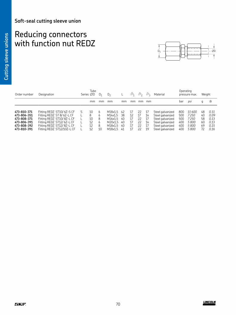
Cutt
ing s
leev
e unio
ns
Soft-seal cutting sleeve union
Reducing connectors with function nut REDZ
Order number Designation SeriesTube ∅D D1 D2 L 1 2 3 Material
Operating pressure max Weight
mm mm mm mm mm mm mm bar psi g lb
473-810-371 Fitting REDZ ST10/ 6Z-S CF S 10 6 M18x1,5 42 17 22 17 Steel galvanized 800 11 600 48 0.11473-806-351 Fitting REDZ ST 8/ 6Z-L CF L 8 6 M14x1,5 38 12 17 14 Steel galvanized 500 7 250 40 0.09473-808-371 Fitting REDZ ST10/ 8Z-L CF L 10 8 M16x1,5 40 17 22 17 Steel galvanized 500 7 250 58 0.13473-806-391 Fitting REDZ ST12/ 6Z-L CF L 12 6 M20x1,5 40 17 22 14 Steel galvanized 400 5 800 60 0.13473-808-392 Fitting REDZ ST12/ 8Z-L CF L 12 8 M18x1,5 40 17 22 17 Steel galvanized 400 5 800 69 0.15473-810-391 Fitting REDZ ST12/10Z-L CF L 12 10 M18x1,5 41 17 22 19 Steel galvanized 400 5 800 72 0.16
D1 ∅D
70

Cutt
ing s
leev
e unio
ns
Soft-seal cutting sleeve union
Cone plugs VKA
∅D
L
Order number Designation SeriesTube ∅D L Material
Operating pressure max Weight
mm mm bar psi g lb
Steel galvanized223-10297-5 BLANKING PLUG ST VKA 6-L/S CF L/S 6 18,5 Steel galvanized 800 11 600 6 0.01460-708-001 BLANKING PLUG ST VKA 8-L CF L 8 18,5 Steel galvanized 500 7 250 9 0.02223-10297-6 BLANKING PLUG ST VKA10-L/S CF L/S 10 15 Steel galvanized 800 11 600 15 0.03223-10297-9 BLANKING PLUG ST VKA12-L/S CF L/S 12 21 Steel galvanized 630 9 140 21 0.05223-10297-7 BLANKING PLUG ST VKA20-S CF S 20 28,5 Steel galvanized 420 6 090 78 0.17223-14241-2 BLANKING PLUG ST VKA30-S CF S 30 30,5 Steel galvanized 420 6 090 180 0.40
Stainless steel223-14241-9 BLANKING PLUG VA VKA10-L/S L/S 10 15 Stainless steel 630 9 140 15 0.03223-10297-1 BLANKING PLUG VA VKA20-S S 20 28,5 Stainless steel 400 5 800 78 0.17223-14241-5 BLANKING PLUG VA VKA30-S S 30 30 5 Stainless steel 400 5 800 180 0.40
71

Adapter fittings
Adapte
rs
Description
Adapter fittings are used where no standard fittings are available or
may require too much space In fact, adapter fittings are not an ideal
solution due to the risk of an additional leakage point in the system
Therefore, the adapter fitting sealing, material, design and operation
pressure must be considered during the selection process SKF offers
adapters for various applications with suitable operating pressures,
fittings, seals and designs
Adapter fittings are available in various designs to serve different
application requirements for system pressure:
• 45 bar designs
• 350 bar designs
• LL (very light, max 100 bar)
• L (light, max 500 bar)
• S (heavy, max 800 bar)
Features and benefits
• Fast and virtually leakage-free connection
• Designs for almost every application
• Space-saving small design
72

Adapte
rs
Applications
• Food and beverage industry
• Renewable energy industry
• Construction machinery
• Material handling
• On-road vehicles
• Machine tools
• Etc
73

Adapte
rs
Adapter fittings
Reducing connectors with cylindrical thread for operating pressures up to 45 bar (sealed by flat washer acc. to DIN 7603)
D1
L2
L1
D2
Order number Designation D1 D2 L1 L2 Material Weight
mm mm mm mm mm g lb
843-130-021 ADAPTER ST M 3A X M 5I CF M3 M5 22 10 3 1) Steel, galvanized surface 4 0.01843-130-022 ADAPTER ST M 4A X M 5I CF M4 M5 22 10 3 1) Steel, galvanized surface 5 0.01843-130-023 ADAPTER ST M 5A X M 5I CF M5 M5 22 10 3 1) Steel, galvanized surface 11 0.02
1) Female thread
Reducing connectors with tapered thread for operating pressures up to 45 bar
Order number Designation G1 G2 L1 L2 Material Weight
mm mm mm mm mm g lb
406-044-S1 ADAPTER ST M10X1KA X R1/4I CF M10×1 tap R 1/4 22,5 8 17 Steel, galvanized surface 20 0.04
G1
G2
L2
L1
74

Adapte
rs
Adapter for pressure gauges for operating pressures up to 45 bar (sealed by flat washer acc. to DIN 7603)
∅D
D1
L1
L2
Order number Designation SeriesTube ∅D D1 L1 L2 Material
Operating pressure max Weight
mm mm mm mm mm bar psi g lb
248-610 01 ADAPTER L 6 G 1/4 46 22 17 Brass 45 650 30 0.07
Order number Designation D1 D2 L1 L2 Material Weight
mm mm mm mm mm g lb
Steel, galvanized surface401-013-161 ADAPTER ST G1/4A X G1/2I CF G 1/4 A G 1/2 40 12 27 Steel, galvanized surface 114 0.25401-011-132 ADAPTER ST G1/2A X G1I CF G 1/2 A G 1 49 14 41 Steel, galvanized surface 222 0.49433-890-131 ADAPTER ST G1/2A X G1 1/4I CF G 1/2 A G 1 1/4 53 14 55 Steel, galvanized surface 210 0.46401-013-171 ADAPTER ST G3/4A X G1/2I CF G 3/4 A G 1/2 41 16 32 Steel, galvanized surface 140 0.31406-024 ADAPTER MS M10X1A X G1/8I CF M10×1 G 1/8 20 8 14 Steel, galvanized surface 15 0.03P-78 01 ADAPTER ST M12X1A X G1/4I CF M12×1 G 1/4 27 8,5 19 Steel, galvanized surface 31 0.07401-016-371 ADAPTER ST M16X1,5A X G1/4I CF M16×1 5 G 1/4 30 12 19 Steel, galvanized surface 39 0.09243-001 10 ADAPTER ST M16X1,5A X G1/2I CF M16×1 5 G 1/2 31 9 27 Steel, galvanized surface 60 0.13267-001 36 ADAPTER ST M18X1,5A X G3/8I CF M18×1 5 G 3/8 32 10 22 Steel, galvanized surface 50 0.11243-001 20 ADAPTER ST M18X1,5A X G1/2I CF M18×1 5 G 1/2 32 10 27 Steel, galvanized surface 59 0.1344-1755-2029 ADAPTER ST M20X1,5A X G1/4I CF M20×1 5 G 1/4 28 12 24 Steel, galvanized surface 59 0.13
Brass267-001 47 ADAPTER MS G3/8A X G3/4I G 3/8 A G 1/4 31 10 22 Brass 60 0.13267-001 60 ADAPTER MS G3/8A X G1/2I G 3/8 A G 1/2 34 10 27 Brass 78 0.17401-019-132 ADAPTER MS G1/2A X G1/8I G 1/2 A G 1/8 24 12 27 Brass 22 0.05DZ333 ADAPTER MS G1/2A X G1/4I G 1/2 A G 1/4 24 12 27 Brass 64 0.14401-013-131 ADAPTER MS G1/2A X G1/2I G 1/2 A G 1/2 40,5 12 27 Brass 107 0.24DZ334 ADAPTER MS G1/2A X G3/8I G 1/2 A G 3/8 31 12 27 Brass 83 0.18267-001 03 ADAPTER MS G1/2A X G3/4I G 1/2 A G 3/4 40 12 36 Brass 166 0.37401-016-312 ADAPTER MS M10X1A X G1/4I M10×1 G 1/4 26,5 7,5 17 Brass 25 0.06401-019-352 ADAPTER MS M14X1,5X1A X G1/8I M14×1,5 G 1/8 20 9 17 Brass 24 0.05
L2
L1
D2
D1
Adapter fittings
Reducing connectors with cylindrical thread for operating pressures up to 45 bar (sealed by flat washer acc. to DIN 7603)
75
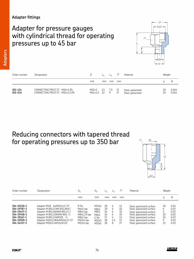
Adapte
rs
Reducing connectors with tapered thread for operating pressures up to 350 bar
Order number Designation G1 G2 L1 L2 Material Weight
mm mm mm mm mm g lb
304-19230-1 Adapter R1/8 AxM10x1,0 I CF R 1/8 M10x1 18 6 13 Steel, galvanized surface 20 0.04304-19787-1 Adapter M 8X1,0 IXM 6X1,0KA C M6x1 tap M8x1 20 6 10 Steel, galvanized surface 6 0.01304-19437-1 Adapter M 8X1,0KAXM 8X1,0 I C M8x1 tap M8x1 16 6 10 Steel, galvanized surface 5 0.01304-19548-1 Adapter M 8X1,25KAXM 8X1 I C M8x1 25 tap M8x1 16 6 10 Steel, galvanized surface 10 0,02304-19167-1 Adapter M 8X1,0 AXR1/8 I C M8x1 tap G 1/8 17 6 13 Steel, galvanized surface 10 0.02304-19509-1 Adapter M10x1,0KAxM10x1,0 I CF M10x1 tap M10x1 18 4 5 13 Steel, galvanized surface 9 0.02304-16337-1 Adapter M10x1 IxM12x1K A Z M12x1 tap M10x1 18 8 17 Steel, galvanized surface 15 0.03
G1
G2
L2
L1
Adapter fittings
Adapter for pressure gauges with cylindrical thread for operating pressures up to 45 bar
Order number Designation D L1 L2 Material Weight
mm mm mm mm g lb
301-134 CONNECTING PIECE ST - M10×1 ZN M10×1 23 7,5 17 Steel, galvanized 20 0.044301-034 CONNECTING PIECE ST - M14×1,5 ZN M14×1,5 22 9 17 Steel, galvanized 20 0.044
G1/4
17
L1
L2
∅4
D
76
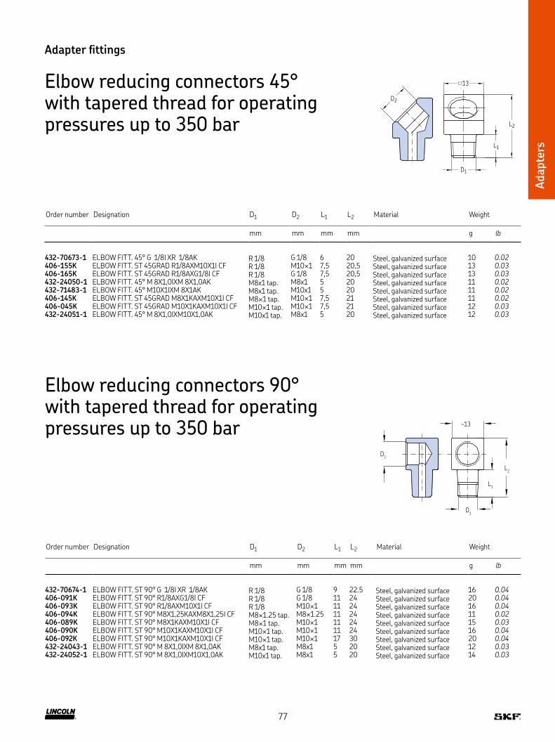
Adapte
rs
Adapter fittings
Elbow reducing connectors 45° with tapered thread for operating pressures up to 350 bar
D2
13
D1
L1
L2
Order number Designation D1 D2 L1 L2 Material Weight
mm mm mm mm g lb
432-70673-1 ELBOW FITT 45° G 1/8I XR 1/8AK R 1/8 G 1/8 6 20 Steel, galvanized surface 10 0.02406-155K ELBOW FITT ST 45GRAD R1/8AXM10X1I CF R 1/8 M10×1 7,5 20,5 Steel, galvanized surface 13 0.03406-165K ELBOW FITT ST 45GRAD R1/8AXG1/8I CF R 1/8 G 1/8 7,5 20,5 Steel, galvanized surface 13 0.03432-24050-1 ELBOW FITT 45° M 8X1,0IXM 8X1,0AK M8x1 tap M8x1 5 20 Steel, galvanized surface 11 0.02432-71483-1 ELBOW FITT 45° M10X1IXM 8X1AK M8x1 tap M10x1 5 20 Steel, galvanized surface 11 0.02406-145K ELBOW FITT ST 45GRAD M8X1KAXM10X1I CF M8×1 tap M10×1 7,5 21 Steel, galvanized surface 11 0.02406-045K ELBOW FITT ST 45GRAD M10X1KAXM10X1I CF M10×1 tap M10×1 7,5 21 Steel, galvanized surface 12 0.03432-24051-1 ELBOW FITT 45° M 8X1,0IXM10X1,0AK M10x1 tap M8x1 5 20 Steel, galvanized surface 12 0.03
Elbow reducing connectors 90° with tapered thread for operating pressures up to 350 bar
Order number Designation D1 D2 L1 L2 Material Weight
mm mm mm mm g lb
432-70674-1 ELBOW FITT ST 90° G 1/8I XR 1/8AK R 1/8 G 1/8 9 22 5 Steel, galvanized surface 16 0.04406-091K ELBOW FITT ST 90° R1/8AXG1/8I CF R 1/8 G 1/8 11 24 Steel, galvanized surface 20 0.04406-093K ELBOW FITT ST 90° R1/8AXM10X1I CF R 1/8 M10×1 11 24 Steel, galvanized surface 16 0.04406-094K ELBOW FITT ST 90° M8X1,25KAXM8X1,25I CF M8×1 25 tap M8×1 25 11 24 Steel, galvanized surface 11 0.02406-089K ELBOW FITT ST 90° M8X1KAXM10X1I CF M8×1 tap M10×1 11 24 Steel, galvanized surface 15 0.03406-090K ELBOW FITT ST 90° M10X1KAXM10X1I CF M10×1 tap M10×1 11 24 Steel, galvanized surface 16 0.04406-092K ELBOW FITT ST 90° M10X1KAXM10X1I CF M10×1 tap M10×1 17 30 Steel, galvanized surface 20 0.04432-24043-1 ELBOW FITT ST 90° M 8X1,0IXM 8X1,0AK M8x1 tap M8x1 5 20 Steel, galvanized surface 12 0.03432-24052-1 ELBOW FITT ST 90° M 8X1,0IXM10X1,0AK M10x1 tap M8x1 5 20 Steel, galvanized surface 14 0.03
~13
D2
D1
L1
L2
77

Adapte
rs
Adapter fittings
Reducing connectors RI with cylindrical thread for operating pressures up to 400 bar D D
1
Order number DesignationTube ∅D ∅D1 L 1 L 2 Material
Operating pressure max Weight
mm mm mm mm mm bar psi g lb
Steel galvanized222-12578-5 BUSHING ST RI G 1/8XG 1/4 CF G 1/8 G 1/4 31 8 19 Steel galvanized 400 5 800 42 0.09222-12521-5 BUSHING ST RI G 1/4XG 1/8 CF G 1/4 G 1/8 28 12 19 Steel galvanized 400 5 800 38 0.08222-12521-6 BUSHING ST RI G 1/4XG 3/8 CF G 1/4 G 3/8 36 12 24 Steel galvanized 400 5 800 69 0.15222-12521-4 BUSHING ST RI G 1/4XG 1/2 CF G 1/4 G 1/2 40 12 30 Steel galvanized 400 5 800 116 0.26222-13678-2 BUSHING ST RI G 3/8XG 1/8 CF G 3/8 G 1/8 22 5 12 22 Steel galvanized 400 5 800 39 0.09222-12578-4 BUSHING ST RI G 3/8XG 1/4 CF G 3/8 G 1/4 36 12 22 Steel galvanized 400 5 800 68 0.15222-12578-8 BUSHING ST RI G 3/8XG 1/2 CF G 3/8 G 1/2 41 12 30 Steel galvanized 400 5 800 125 0.28222-12578-3 BUSHING ST RI G 3/8XG 3/4 CF G 3/8 G 3/4 44 12 36 Steel galvanized 315 4 570 183 0.40222-12521-2 BUSHING ST RI G 1/2XG 1/4 CF G 1/2 G 1/4 24 14 27 Steel galvanized 315 4 570 56 0.1296-3102-0058 BUSHING ST RI G 1/2XG 1/8 CF G 1/2 G 1/8 24 14 27 Steel galvanized 400 5 800 66 0.15222-12599-2 BUSHING ST RI G 1/2XG 3/8 CF G 1/2 G 3/8 36 14 27 Steel galvanized 315 4 570 94 0.21222-12047-2 BUSHING ST RI G 1/2XG 3/4 CF G 1/2 G 3/4 46 14 36 Steel galvanized 315 4 570 182 0.40222-12599-3 BUSHING ST RI G 1/2XG 1 CF G 1/2 G 1 49 14 41 Steel galvanized 315 4 570 221 0.49222-12578-2 BUSHING ST RI G 1/2XG 1 1/4 CF G 1/2 G 1 1/4 53 14 55 Steel galvanized 160 2 320 482 1.06222-13678-1 BUSHING ST RI G 3/4XG 1/4 CF G 3/4 G 1/4 26 16 32 Steel galvanized 315 4 570 103 0.23222-12578-9 BUSHING ST RI G 3/4XG 3/8 CF G 3/4 G 3/8 26 16 32 Steel galvanized 315 4 570 87 0.19222-12047-8 BUSHING ST RI G 3/4XG 1/2 CF G 3/4 G 1/2 41 16 32 Steel galvanized 315 4 570 143 0.32222-12047-4 BUSHING ST RI G 3/4XG 1 CF G 3/4 G 1 51 16 41 Steel galvanized 315 4 570 235 0.5296-3129-0058 BUSHING ST RI G 3/4XG 1 1/4 CF G 3/4 G 1 1/4 55 16 55 Steel galvanized 160 2 320 481 1.06222-12599-9 BUSHING ST RI G 1XG 1/2 CF G 1 G 1/2 29 18 41 Steel galvanized 315 4 570 157 0.35222-13678-4 BUSHING ST RI G 1XG 3/8 CF G 1 G 3/8 29 18 41 Steel galvanized 315 4 570 179 0.3996-3106-0058 BUSHING ST RI G 1XG 1/4 CF G 1 G 1/4 29 18 41 Steel galvanized 315 4 570 195 0.43222-12599-5 BUSHING ST RI G 1XG 3/4 CF G 1 G 3/4 47 18 41 Steel galvanized 315 4 570 278 0.61222-13670-1 BUSHING ST RI G 1XG 1 1/4 CF G 1 G 1 1/4 57 18 55 Steel galvanized 160 2 320 530 1.1796-3133-0058 BUSHING ST RI G 1XG 1 1/2 CF G 1 G 1 1/2 59 18 60 Steel galvanized 160 2 320 585 1.29222-13678-8 BUSHING ST RI G 1 1/4XG 1/2 CF G 1 1/4 G 1/2 32 20 50 Steel galvanized 160 2 320 308 0.68222-12521-8 BUSHING ST RI G 1 1/4XG 3/4 CF G 1 1/4 G 3/4 32 20 50 Steel galvanized 160 2 320 267 0.59222-12599-6 BUSHING ST RI G 1 1/4XG 1 CF G 1 1/4 G 1 32 20 50 Steel galvanized 160 2 320 458 1.01222-11053-1 BUSHING ST RI G 1 1/2XG 1/2 CF G 1 1/2 G 1/2 36 22 55 Steel galvanized 160 2 320 477 1.0596-3112-0058 BUSHING ST RI G 1 1/2XG 3/4 CF G 1 1/2 G 3/4 36 22 55 Steel galvanized 160 2 320 402 0.89222-13678-3 BUSHING ST RI G 1 1/2XG 1 CF G 1 1/2 G 1 36 22 55 Steel galvanized 160 2 320 337 0.7496-3136-0058 BUSHING ST RI G 1 1/2XG 1 1/4 CF G 1 1/2 G 1 1/4 58 22 55 Steel galvanized 160 2 320 542 1.2096-3137-0058 BUSHING ST RI G 2XG 1 1/2 CF G 2 G 1 1/2 62 24 70 Steel galvanized 160 2 320 990 2.18
Stainless steel222-13618-1 BUSHING VA RI G 1/8XG 1/4 G 1/8 G 1/4 31 8 19 Stainless steel 400 5 800 42 0.09222-10365-3 BUSHING VA RI G 1/4XG 1/8 G 1/4 G 1/8 28 12 19 Stainless steel 400 5 800 38 0.08222-13618-5 BUSHING VA RI G 1/4XG 1/2 G 1/4 G 1/2 40 12 30 Stainless steel 400 5 800 116 0.26222-14180-7 BUSHING VA RI G 3/8XG 1/4 G 3/8 G 1/4 36 12 22 Stainless steel 400 5 800 68 0.15222-13618-2 BUSHING VA RI G 3/8XG 1/2 G 3/8 G 1/2 41 12 30 Stainless steel 400 5 800 125 0.28222-14180-3 BUSHING VA RI G 1/2XG 1/4 G 1/2 G 1/4 24 14 27 Stainless steel 315 4 570 56 0.12222-14180-6 BUSHING VA RI G 1/2XG 3/8 G 1/2 G 3/8 36 14 27 Stainless steel 315 4 570 94 0.21222-14180-9 BUSHING VA RI G 3/4XG 3/8 G 3/4 G 3/8 26 16 32 Stainless steel 315 4 570 87 0.19222-13618-3 BUSHING VA RI G 3/4XG 1/2 G 3/4 G 1/2 41 16 32 Stainless steel 315 4 570 143 0.32222-14180-5 BUSHING VA RI G 1XG 3/4 G 1 G 3/4 47 18 41 Stainless steel 315 4 570 278 0.61
78

Adapte
rs
Adapter fittings
Screw plugs VSTI
D1
L
Order number DesignationTube ∅D D1 L Material
Operating pressure max Weight
mm mm mm bar psi g lb
Steel galvanized466-419-001 PLUG 6-SOCK ST VSTI G1/8 -ED G 1/8 14 8 5 Steel, galvanized 400 5 800 8 0.02223-13702-1 PLUG 6-SOCK ST VSTI G 1/4 -ED CF G 1/4 19 12 6 Steel, galvanized 400 5 800 20 0.04223-13702-7 PLUG 6-SOCK ST VSTI G 1/2 -ED CF G 1/2 27 14 10 Steel, galvanized 400 5 800 51 0.11223-13702-6 PLUG 6-SOCK ST VSTI G 3/4 -ED CF G 3/4 32 16 12 Steel, galvanized 400 5 800 79 0.17223-10530-4 PLUG 6-SOCK ST VSTI G1 -ED CF G 1 39,9 16 17 Steel, galvanized 400 5 800 130 0.29466-429-001 PLUG 6-SOCK ST VSTI M8X1 -ED M8x1 mm 12 8 4 Steel, galvanized 400 5 800 7 0.02466-431-001 PLUG 6-SOCK ST VSTI M10X1 -ED M10x1 mm 14 8 5 Steel, galvanized 400 5 800 8 0.02466-439-001 PLUG 6-SOCK ST VSTI M18X1 5 -ED CF M18x1,5 mm 23,9 14 8 Steel, galvanized 400 5 800 32 0.07
Stainless steel223-13702-5 PLUG 6-SOCK VA VSTI G1/4 -ED G 1/4 19 12 6 Stainless steel 400 5 800 20 0.04223-13702-9 PLUG 6-SOCK VA VSTI G1/2 -ED G 1/2 27 14 10 Stainless steel 400 5 800 51 0.11
Vent plugs with profile seal acc. to ISO 9974-2
Order number Designation D1 L MaterialOperating pressure max Weight
mm mm mm bar psi g lb
466-431-006 PLUG ST M10X1 CF M10x1 7 10 Steel, galvanized 10 0.02466-431-005 PLUG ST M10X1 CF M10x1 7 5 Steel, galvanized 10 0.02466-431-009 PLUG ST G 1/8 CF G 1/8 7 5 Steel, galvanized 11 0.02
D1
L
79

Adapte
rs
Adapter fittings
Banjo fittings, rotatable
Order number Designation Tube ∅ ∅ D1 ∅ D2
Speed max
Operation pressure max Material Weight
mm in in min-1 bar psi g lb
626-25716-2 Swivel 90° G1/4AxG1/4A F – G1/4 male G1/4 male 80 100 1 450 Steel galvanized 105 0.23626-25540-2 Swivel 90° G1/4AxG1/8A F – G1/4 male G1/8 male 80 100 1 450 Steel galvanized 105 0.23626-26700-2 Swivel 90° G1/8AxD 4 F 4 – G1/8 male 80 100 1 450 Steel galvanized 95 0.21626-25438-2 Swivel 90° G1/8AxD 6 F 6 – G1/8 male 80 100 1 450 Steel galvanized 100 0.22626-26701-2 Swivel 90° G1/4AxD 4 F 4 – G1/4 male 80 100 1 450 Steel galvanized 105 0.23626-25717-2 Swivel 90° G1/4AxD 6 F 6 – G1/4 male 80 100 1 450 Steel galvanized 102 0.22626-25720-2 Swivel straight G1/8AxG1/4A CF – G1/8 G1/4 80 100 1 450 Steel galvanized 75 0.16626-26696-2 Swivel straight G1/8AXD 4 CF 4 – G1/8 80 100 1 450 Steel galvanized 105 0.23
20
R1/4
15
22
38
53
17
28
40
15
R1/4
Order number Designation Tube ∅ ∅ D1 ∅ D2
Speed max
Operation pressure max Material Weight
mm in in min-1 bar psi g lb
91308 Straight swivel 1/8 NPT – 1/8 NPT 1/8 NPT 1 50 725 Steel galvanized 20 0.04223-12567-1 Swivel 90° 1/8 NPT – 1/8 NPT 1/8 NPT 1 50 725 Steel galvanized 40 0.08626-25702-1 Swivel R1/4XR1/4 MS – R1/4 male R1/4 female 1 200 2 900 Brass 102 0.22
1/81/8
91308
1/8
1/8
223-12567-1
626-25702-1
30
G1/4
34.5
A
A
44.5
12.5
G1/4
60
B
A
626-2 626-25720-2 626-26696-2
80

Adapte
rs
Order number Designation Tube ∅D Thread1 Thread2
Speed max
Oil pressure max
Air pressure max Material Weight
mm mm mm min-1 bar psi bar psi g lb
DLY930-2 Rotating joint 8 G 1/4 A M14x1,5 1400 20 1) 290 8 116 brass 246 0.54DLY931 Rotating joint 8 R 1/8 tap M14x1,5 1400 20 1) 290 8 116 brass 244 0.54DLY932 Rotating joint 6 R1/4 M10x1 1400 5 72 – – Aluminium 65 0.14
Adapter fittings
Banjo fittings, rotatable
M10X1
R1/4
81

Quic
k co
nnec
tors
Quick connectors
Quic
k co
nnec
tors
Description
SKF quick connectors are the faster alternative when it comes to
connecting pipes Push-in type connectors are available for fast
establishment of secure connections Simply plug the end of the line
into the pre-installed connector – all done! No wrench is required
Connections can be made more easily and quickly, especially in diffi-
cult-to-access areas Push-in type fittings can be used to connect
the entire system of lines from the pump to the metering devices,
pressure switches, etc – all the way to the lubrication points
The fittings feature internal claws to hold the tubing tight, even at
350 bar (5076 psi) They are equally suitable for plastic and steel
tubing Two versions of quick connectors are offered by SKF:
• Single-seal quick connectors (350 bar, 5076 psi) suitable for grease lubrication systems
• Triple-seal quick connectors (300 bar, 4350 psi) suitable for oil and grease lubrication systems
Features and benefits
• Fast and virtually leakage-free connection
• No wrench tightening required
• Time savings due to easy and quick system assembly
• Connections in systems (without system pressure) can be
easily opened and reclosed again
• Protection against penetrating dirt
82

Quic
k co
nnec
tors
Applications
• Food and beverage industry
• Renewable energy industry
• Construction machinery
• Asphalt mixing plants
• Agricultural machines
• Material handling
• On-road vehicles
• Etc
83

Quick connectors
Single-seal quick connectors (350 bar)
Quic
k co
nnec
tors
Description
SKF single-seal quick connectors have one O-ring They are suitable
for grease lubrication systems with system pressures up to 350 bar
Features and benefits
• Suitable for grease
• Smaller
• Protection caps needed under harsh conditions
• Max operating pressure 350 bar
• For tube ∅6 mm
• Marking of the collet: with groove
• Surface: nickel-plated C5M (sea water proof)
• Pipe sealing, expansion ring for collet chuck
• Plastic pipes can be used without claw groove
• Thread sealing via spring ring
Inner seal
Tube
Claw
Thread
Body
Thread seal
84

Quic
k co
nnec
tors
Single-seal quick connectors
Straight screw-in connectors
∅B
∅D
L2
L1
G
2
1
∅D G
L2
L1
2
1
∅B
Straight screw-in connectors with PTFE threaded seal
Order number DesignationTube ∅D G ∅B L1 L2 1 2 Seal Material
Operating pressure max
Weight (100 pcs)
mm mm mm mm mm mm mm bar psi g lb
226-14139-1 Push-in fitt GEZM 6-1/4 6 G 1/4 18,5 12 25,5 17 4 NBR Brass, nickel-plated 350 5 080 2 000 4.41
Order number DesignationTube ∅D G ∅B L1 L2 1 2 Seal Material
Operating pressure max
Weight (100 pcs)
mm mm mm mm mm mm mm bar psi g lb
226-14111-1 Push-in fitt GEKM S 6-1/8 6 R 1/8 13,2 7 5 22 12 4 NBR Brass, nickel-plated 350 5 080 1 000 2.21226-10205-5 Push-in fitt GEZM S 6-1/4 6 G 1/4 15,2 7 21,5 14 4 NBR Brass, nickel-plated 350 5 080 1 400 3.09
85
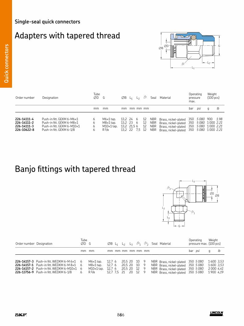
Quic
k co
nnec
tors
Cuti
ing s
leev
e fitt
ings
Quic
k co
nnec
tors
Single-seal quick connectors
Adapters with tapered thread∅D
∅BG
L2
L1
∅B∅D
G
L1
L2
L3
1
2
Banjo fittings with tapered thread
Order number DesignationTube ∅D G ∅B L1 L2 Seal Material
Operating pressure max
Weight (100 pcs)
mm mm mm mm mm mm bar psi g lb
226-14111-4 Push-in fitt GEKM 6-M6×1 6 M6×1 tap 13,2 24 6 12 NBR Brass, nickel-plated 350 5 080 900 1.98226-14111-2 Push-in fitt GEKM 6-M8×1 6 M8×1 tap 13,2 23 6 12 NBR Brass, nickel-plated 350 5 080 1 000 2.21226-14111-3 Push-in fitt GEKM 6-M10×1 6 M10×1 tap 13,2 21,5 6 12 NBR Brass, nickel-plated 350 5 080 1 000 2.21226-10622-8 Push-in fitt GEKM 6-1/8 6 R 1/8 13,2 22 7,5 12 NBR Brass, nickel-plated 350 5 080 1 000 2.21
Order number DesignationTube ∅D G ∅B L1 L2 L3 1 2 Seal Material
Operating pressure max
Weight (100 pcs)
mm mm mm mm mm mm mm mm bar psi g lb
226-14157-3 Push-in fitt WEDKM 6-M 6×1 6 M6×1 tap 12,7 6 20,5 20 10 9 NBR Brass, nickel-plated 350 5 080 1 600 3,53226-14157-1 Push-in fitt WEDKM 6-M 8×1 6 M8×1 tap 12,7 6 20,5 20 10 9 NBR Brass, nickel-plated 350 5 080 1 600 3,53226-14157-2 Push-in fitt WEDKM 6-M10×1 6 M10×1 tap 12,7 6 20,5 20 12 9 NBR Brass, nickel-plated 350 5 080 2 000 4,41226-13756-9 Push-in fitt WEDKM 6-1/8 6 R 1/8 12,7 7,5 21 20 12 9 NBR Brass, nickel-plated 350 5 080 1 900 4,19
8686
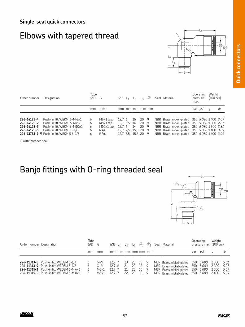
Quic
k co
nnec
tors
Single-seal quick connectors
Elbows with tapered thread∅B
∅D
G
L1
L2
L3
∅B∅D
G
L1
L2
L3
1
2
Banjo fittings with O-ring threaded seal
Order number DesignationTube ∅D G ∅B L1 L2 L3 Seal Material
Operating pressure max
Weight (100 pcs)
mm mm mm mm mm mm mm bar psi g lb
226-14123-4 Push-in fitt WEKM 6-M 6×1 6 M6×1 tap 12,7 6 15 20 9 NBR Brass, nickel-plated 350 5 080 1 400 3.09226-14123-2 Push-in fitt WEKM 6-M 8×1 6 M8×1 tap 12,7 6,5 14 20 9 NBR Brass, nickel-plated 350 5 080 1 300 2.87226-14123-3 Push-in fitt WEKM 6-M10×1 6 M10×1 tap 12,7 6 14 20 9 NBR Brass, nickel-plated 350 5 080 1 500 3.31226-14123-5 Push-in fitt WEKM 6-1/8 6 R 1/8 12,7 7,5 15,5 20 9 NBR Brass, nickel-plated 350 5 080 1 400 3.09226-13753-9 1) Push-in fitt WEKM S 6-1/8 6 R 1/8 12,7 7,5 15,5 20 9 NBR Brass, nickel-plated 350 5 080 1 400 3.09
1) with threaded seal
Order number DesignationTube ∅D G ∅B L1 L2 L3 1 2 Seal Material
Operating pressure max
Weight (100 pcs)
mm mm mm mm mm mm mm mm bar psi g lb
226-11313-8 Push-in fitt WEDZM 6-1/4 6 G 1/4 12,7 7 23 20 15 9 NBR Brass, nickel-plated 350 5 080 2 500 5.51226-11313-9 Push-in fitt WEDZM 6-1/8 6 G 1/8 12,7 6 21 20 12 9 NBR Brass, nickel-plated 350 5 080 2 300 5.07226-11315-1 Push-in fitt WEDZM 6-M 6×1 6 M6×1 12,7 7 21 20 10 9 NBR Brass, nickel-plated 350 5 080 2 300 5.07226-11315-2 Push-in fitt WEDZM 6-M 8×1 6 M8×1 12,7 7 22 20 10 9 NBR Brass, nickel-plated 350 5 080 2 400 5.29
87
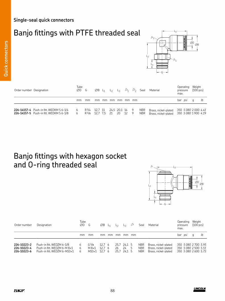
Quic
k co
nnec
tors
Single-seal quick connectors
Banjo fittings with PTFE threaded seal
∅B∅D
G
L1
L2
L3
1
2
∅B∅D
G
L1
L2
L3
Banjo fittings with hexagon socket and O-ring threaded seal
Order number DesignationTube ∅D G ∅B L1 L2 L3 Seal Material
Operating pressure max
Weight (100 pcs)
mm mm mm mm mm mm mm bar psi g lb
226-10223-2 Push-in fitt WEDZM 6-1/8 6 G 1/8 12,7 6 25,7 24,1 5 NBR Brass, nickel-plated 350 5 080 2 700 5.95226-10223-4 Push-in fitt WEDZM 6-M 8×1 6 M 8×1 12,7 6 26 24 5 NBR Brass, nickel-plated 350 5 080 2 500 5.51226-10223-6 Push-in fitt WEDZM 6-M10×1 6 M10×1 12,7 6 25,7 24,1 5 NBR Brass, nickel-plated 350 5 080 2 600 5.73
Order number DesignationTube ∅D G ∅B L1 L2 L3 1 2 Seal Material
Operating pressure max
Weight (100 pcs)
mm mm mm mm mm mm mm mm bar psi g lb
226-14157-4 Push-in fitt WEDKM S 6-1/4 6 R 1/4 12,7 11 24,5 20,1 14 9 NBR Brass, nickel-plated 350 5 080 2 000 4.41226-14157-5 Push-in fitt WEDKM S 6-1/8 6 R 1/8 12,7 7,5 21 20 12 9 NBR Brass, nickel-plated 350 5 080 1 900 4.19
88

Quic
k co
nnec
tors
Order number DesignationTube ∅D G D1 L1 L2 L3 Seal Material
Operating pressure max
Weight
mm mm mm mm mm mm mm bar psi g lb
226-14097-5 Push-in fitt TSM S 6-1/4 6 R 1/4 G 1/4 9 23,5 51,5 14 NBR Brass, nickel-plated 350 5 080 50 0.11
Single-seal quick connectors
Screw-in T-connectorsL3
∅D
G
L1
D1
L2
L3
∅B
L2
L1
∅D
2
1
G
Order number DesignationTube ∅D G ∅B L1 L2 L3 1 2 Seal Material
Operating pressure max
Weight
mm mm mm mm mm mm mm mm bar psi g lb
226-10159-1 Push-in fitt TEDZM S 6-1/8 6 G 1/8 12,7 5,5 20,3 40,2 9 9 NBR Brass, nickel-plated 350 5 080 27 0.06226-10159-9 Push-in fitt TEDZM S 6-1/4 6 G 1/4 12,7 7 22 40 14 9 NBR Brass, nickel-plated 350 5 080 35 0.08
89

Quic
k co
nnec
tors
Single-seal quick connectors
T-connectorsL3
∅D
L1
L2
∅B
Order number DesignationTube ∅D ∅B L1 L2 L3 Seal Material
Operating pressure max
Weight
mm mm mm mm mm mm bar psi g lb
226-14097-4 Push-in fitt TSM 6 6 12,7 20 26 40 6 NBR Brass, nickel-plated 350 5 080 20 0.04
∅BG
L1
L2
L3
∅D
Order number DesignationTube ∅D G ∅B L1 L2 L3 Seal Material
Operating pressure max
Weight
mm mm mm mm mm mm mm bar psi g lb
226-10214-4 Push-in fitt SVM 6-G 1/8 6 G 1/8 12,5 9 17 31,6 17 NBR Brass, nickel-plated 350 5 080 26 0.06226-10214-7 Push-in fitt SVM 6-M 8×1 6 M 8×1 12,5 9 17 31,5 17 NBR Brass, nickel-plated 350 5 080 27 0.06
Straight bulkhead connectors
90

Quic
k co
nnec
tors
Order number DesignationTube ∅D ∅B L Seal Material
Operating pressure max
Weight
mm mm mm bar psi g lb
226-13773-4 Connector GSM 6 6 12 34 NBR Brass, nickel-plated 350 5 080 18 0.04
Single-seal quick connectors
Tube-to-tube connector
∅B ∅D ∅D
L
91

Triple-seal quick connectors
Description
SKF triple-seal quick connectors have three O-rings They are suita-
ble for oil lubrication systems with system pressures up to 300 bar
For a good union, steel pipes or fittings used as hose end fittings
must be prepared with a claw groove Plastic pipes can be connected
directly without an additional claw groove
For metal pipes, a claw groove is required at the end of the pipe
Features and benefits
• Suitable for oil and fluid grease
• Better sealing by three O-rings (leakage-free)
• Max operating pressure 300 bar
• For tube ∅4, 6 and 8 mm
• Marking of the collet: plain
• Surface: collet nickel-plated C4
• Insertion depth for plastic and steel tubing
– ∅4 mm: 19 mm
– ∅6 mm: 22 mm
– ∅8 mm: 24 mm
• Reduction of bending forces
• Sealing for the pipe, expansion ring for collet chuck
• Sealing thread O-ring
Quic
k co
nnec
tors
∅A
C21°
B
Claw grooves
Tube∅
Tube ∅ A +0,3 B ±0,2 C
4 3,1 5 0,3 … 0,76 4,9 6,2 0,4 … 0,98 6,9 6,2 0,5 … 0,9
Tool for the production of pipe ends (cutting and groove-forming) available in the chapter on tools
Thread seal
Tube
Claw
Thread
Body
Inner seal 3
Inner seal 2
Inner seal 1
Claw groove
92
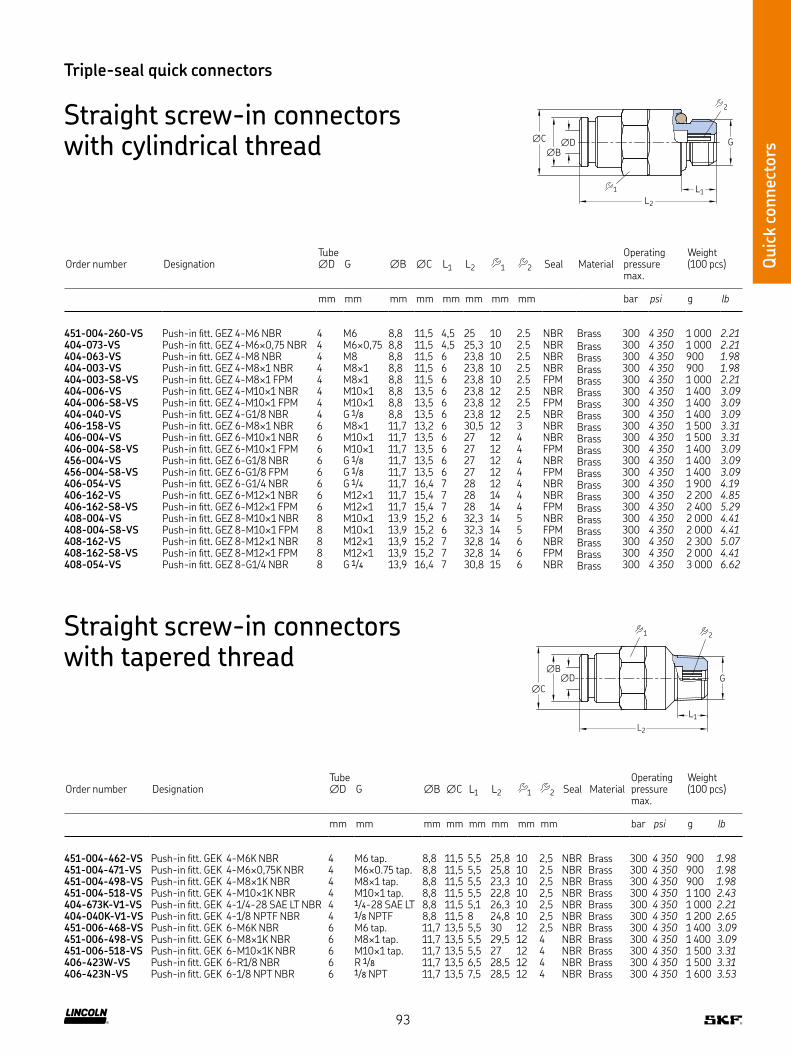
Quic
k co
nnec
tors
Order number DesignationTube ∅D G ∅B ∅C L1 L2 1 2 Seal Material
Operating pressure max
Weight (100 pcs)
mm mm mm mm mm mm mm mm bar psi g lb
451-004-260-VS Push-in fitt GEZ 4-M6 NBR 4 M6 8,8 11,5 4,5 25 10 2 5 NBR Brass 300 4 350 1 000 2.21404-073-VS Push-in fitt GEZ 4-M6×0,75 NBR 4 M6×0,75 8,8 11,5 4,5 25,3 10 2 5 NBR Brass 300 4 350 1 000 2.21404-063-VS Push-in fitt GEZ 4-M8 NBR 4 M8 8,8 11,5 6 23,8 10 2 5 NBR Brass 300 4 350 900 1.98404-003-VS Push-in fitt GEZ 4-M8×1 NBR 4 M8×1 8,8 11,5 6 23,8 10 2 5 NBR Brass 300 4 350 900 1.98404-003-S8-VS Push-in fitt GEZ 4-M8×1 FPM 4 M8×1 8,8 11,5 6 23,8 10 2 5 FPM Brass 300 4 350 1 000 2.21404-006-VS Push-in fitt GEZ 4-M10×1 NBR 4 M10×1 8,8 13,5 6 23,8 12 2 5 NBR Brass 300 4 350 1 400 3.09404-006-S8-VS Push-in fitt GEZ 4-M10×1 FPM 4 M10×1 8,8 13,5 6 23,8 12 2 5 FPM Brass 300 4 350 1 400 3.09404-040-VS Push-in fitt GEZ 4-G1/8 NBR 4 G 1/8 8,8 13,5 6 23,8 12 2 5 NBR Brass 300 4 350 1 400 3.09406-158-VS Push-in fitt GEZ 6-M8×1 NBR 6 M8×1 11,7 13,2 6 30,5 12 3 NBR Brass 300 4 350 1 500 3.31406-004-VS Push-in fitt GEZ 6-M10×1 NBR 6 M10×1 11,7 13,5 6 27 12 4 NBR Brass 300 4 350 1 500 3.31406-004-S8-VS Push-in fitt GEZ 6-M10×1 FPM 6 M10×1 11,7 13,5 6 27 12 4 FPM Brass 300 4 350 1 400 3.09456-004-VS Push-in fitt GEZ 6-G1/8 NBR 6 G 1/8 11,7 13,5 6 27 12 4 NBR Brass 300 4 350 1 400 3.09456-004-S8-VS Push-in fitt GEZ 6-G1/8 FPM 6 G 1/8 11,7 13,5 6 27 12 4 FPM Brass 300 4 350 1 400 3.09406-054-VS Push-in fitt GEZ 6-G1/4 NBR 6 G 1/4 11,7 16,4 7 28 12 4 NBR Brass 300 4 350 1 900 4.19406-162-VS Push-in fitt GEZ 6-M12×1 NBR 6 M12×1 11,7 15,4 7 28 14 4 NBR Brass 300 4 350 2 200 4.85406-162-S8-VS Push-in fitt GEZ 6-M12×1 FPM 6 M12×1 11,7 15,4 7 28 14 4 FPM Brass 300 4 350 2 400 5.29408-004-VS Push-in fitt GEZ 8-M10×1 NBR 8 M10×1 13,9 15,2 6 32,3 14 5 NBR Brass 300 4 350 2 000 4.41408-004-S8-VS Push-in fitt GEZ 8-M10×1 FPM 8 M10×1 13,9 15,2 6 32,3 14 5 FPM Brass 300 4 350 2 000 4.41408-162-VS Push-in fitt GEZ 8-M12×1 NBR 8 M12×1 13,9 15,2 7 32,8 14 6 NBR Brass 300 4 350 2 300 5.07408-162-S8-VS Push-in fitt GEZ 8-M12×1 FPM 8 M12×1 13,9 15,2 7 32,8 14 6 FPM Brass 300 4 350 2 000 4.41408-054-VS Push-in fitt GEZ 8-G1/4 NBR 8 G 1/4 13,9 16,4 7 30,8 15 6 NBR Brass 300 4 350 3 000 6.62
Triple-seal quick connectors
Straight screw-in connectors with cylindrical thread
L2
L1
∅C
∅B
∅D G
2
1
Order number DesignationTube ∅D G ∅B ∅C L1 L2 1 2 Seal Material
Operating pressure max
Weight (100 pcs)
mm mm mm mm mm mm mm mm bar psi g lb
451-004-462-VS Push-in fitt GEK 4-M6K NBR 4 M6 tap 8,8 11,5 5,5 25,8 10 2,5 NBR Brass 300 4 350 900 1.98451-004-471-VS Push-in fitt GEK 4-M6×0,75K NBR 4 M6×0 75 tap 8,8 11,5 5,5 25,8 10 2,5 NBR Brass 300 4 350 900 1.98451-004-498-VS Push-in fitt GEK 4-M8×1K NBR 4 M8×1 tap 8,8 11,5 5,5 23,3 10 2,5 NBR Brass 300 4 350 900 1.98451-004-518-VS Push-in fitt GEK 4-M10×1K NBR 4 M10×1 tap 8,8 11,5 5,5 22,8 10 2,5 NBR Brass 300 4 350 1 100 2.43404-673K-V1-VS Push-in fitt GEK 4-1/4-28 SAE LT NBR 4 1/4-28 SAE LT 8,8 11,5 5,1 26,3 10 2,5 NBR Brass 300 4 350 1 000 2.21404-040K-V1-VS Push-in fitt GEK 4-1/8 NPTF NBR 4 1/8 NPTF 8,8 11,5 8 24,8 10 2,5 NBR Brass 300 4 350 1 200 2.65451-006-468-VS Push-in fitt GEK 6-M6K NBR 6 M6 tap 11,7 13,5 5,5 30 12 2,5 NBR Brass 300 4 350 1 400 3.09451-006-498-VS Push-in fitt GEK 6-M8×1K NBR 6 M8×1 tap 11,7 13,5 5,5 29,5 12 4 NBR Brass 300 4 350 1 400 3.09451-006-518-VS Push-in fitt GEK 6-M10×1K NBR 6 M10×1 tap 11,7 13,5 5,5 27 12 4 NBR Brass 300 4 350 1 500 3.31406-423W-VS Push-in fitt GEK 6-R1/8 NBR 6 R 1/8 11,7 13,5 6,5 28,5 12 4 NBR Brass 300 4 350 1 500 3.31406-423N-VS Push-in fitt GEK 6-1/8 NPT NBR 6 1/8 NPT 11,7 13,5 7,5 28,5 12 4 NBR Brass 300 4 350 1 600 3.53
Straight screw-in connectors with tapered thread
∅C
∅B∅D
L2
L1
G
2 1
93

Quic
k co
nnec
tors
L2
L1
L3
G
∅D
∅B
Order number DesignationTube ∅D G ∅B L1 L2 L3 Seal Material
Operating pressure max
Weight (100 pcs)
mm mm mm mm mm mm mm bar psi g lb
504-161-VS Banjo fitting SWVZ-4-M6 NBR 4 M6 8,8 5 19,5 22,3 9 NBR Brass 300 4350 1300 2.87504-401-S1-VS Banjo fitting SWVZ-4-M5 NBR 4 M5 8,8 5 18 21,8 8 NBR Brass 300 4 350 1 100 2.43504-411-VS Banjo fitting SWVZ-4-M8 NBR 4 M8 8,8 7 20 23,8 12 NBR Brass 300 4 350 1 700 3.75504-401-VS Banjo fitting SWVZ-4-M8×1 NBR 4 M8×1 8,8 7 20 23,8 12 NBR Brass 300 4 350 1 800 3.97504-103-VS Banjo fitting SWVZ-4-M10×1 NBR 4 M10×1 8,8 7 22,5 24,8 14 NBR Brass 300 4 350 2 400 5.29445-519-041-VS Banjo fitting SWVZ-4-G1/8 NBR 4 G 1/8 8,8 7 22,5 24,8 14 NBR Brass 300 4 350 2 400 5.29
Banjo fittings with banjo bolt and cylindrical thread
L
D1∅D
Order number DesignationTube ∅D D1 L Material
Operating pressure max
Weight (100 pcs)
mm mm mm bar psi g lb
454-504-041-VS Connector GS 4 NBR 4 10 38,5 Brass 300 4 350 1 500 3.31406-426-VS Connector GS 6 NBR 6 12 44,5 Brass 300 4 350 2 000 4.41
Triple-seal quick connectors
Tube-to-tube connectors
94
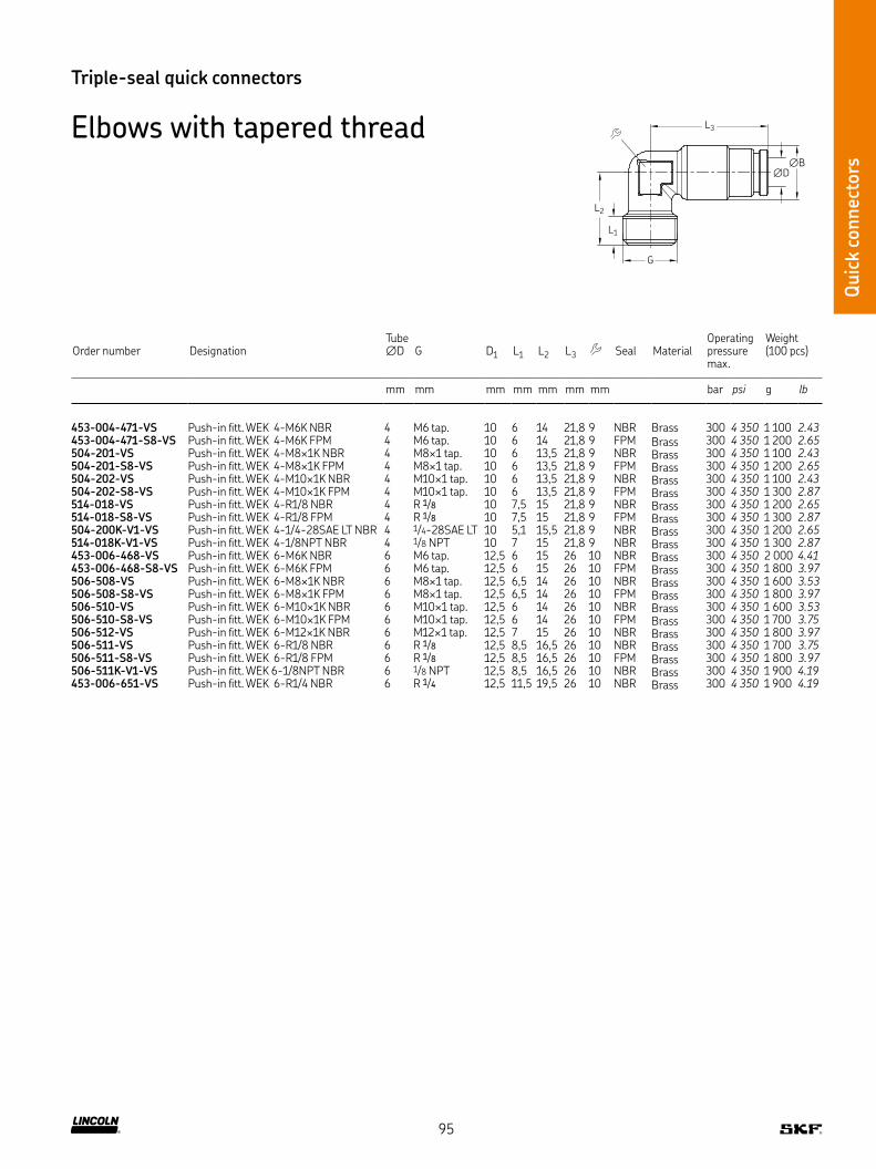
Quic
k co
nnec
tors
Order number DesignationTube ∅D G D1 L1 L2 L3 Seal Material
Operating pressure max
Weight (100 pcs)
mm mm mm mm mm mm mm bar psi g lb
453-004-471-VS Push-in fitt WEK 4-M6K NBR 4 M6 tap 10 6 14 21,8 9 NBR Brass 300 4 350 1 100 2.43453-004-471-S8-VS Push-in fitt WEK 4-M6K FPM 4 M6 tap 10 6 14 21,8 9 FPM Brass 300 4 350 1 200 2.65504-201-VS Push-in fitt WEK 4-M8×1K NBR 4 M8×1 tap 10 6 13,5 21,8 9 NBR Brass 300 4 350 1 100 2.43504-201-S8-VS Push-in fitt WEK 4-M8×1K FPM 4 M8×1 tap 10 6 13,5 21,8 9 FPM Brass 300 4 350 1 200 2.65504-202-VS Push-in fitt WEK 4-M10×1K NBR 4 M10×1 tap 10 6 13,5 21,8 9 NBR Brass 300 4 350 1 100 2.43504-202-S8-VS Push-in fitt WEK 4-M10×1K FPM 4 M10×1 tap 10 6 13,5 21,8 9 FPM Brass 300 4 350 1 300 2.87514-018-VS Push-in fitt WEK 4-R1/8 NBR 4 R 1/8 10 7,5 15 21,8 9 NBR Brass 300 4 350 1 200 2.65514-018-S8-VS Push-in fitt WEK 4-R1/8 FPM 4 R 1/8 10 7,5 15 21,8 9 FPM Brass 300 4 350 1 300 2.87504-200K-V1-VS Push-in fitt WEK 4-1/4-28SAE LT NBR 4 1/4-28SAE LT 10 5,1 15,5 21,8 9 NBR Brass 300 4 350 1 200 2.65514-018K-V1-VS Push-in fitt WEK 4-1/8NPT NBR 4 1/8 NPT 10 7 15 21,8 9 NBR Brass 300 4 350 1 300 2.87453-006-468-VS Push-in fitt WEK 6-M6K NBR 6 M6 tap 12,5 6 15 26 10 NBR Brass 300 4 350 2 000 4.41453-006-468-S8-VS Push-in fitt WEK 6-M6K FPM 6 M6 tap 12,5 6 15 26 10 FPM Brass 300 4 350 1 800 3.97506-508-VS Push-in fitt WEK 6-M8×1K NBR 6 M8×1 tap 12,5 6,5 14 26 10 NBR Brass 300 4 350 1 600 3.53506-508-S8-VS Push-in fitt WEK 6-M8×1K FPM 6 M8×1 tap 12,5 6,5 14 26 10 FPM Brass 300 4 350 1 800 3.97506-510-VS Push-in fitt WEK 6-M10×1K NBR 6 M10×1 tap 12,5 6 14 26 10 NBR Brass 300 4 350 1 600 3.53506-510-S8-VS Push-in fitt WEK 6-M10×1K FPM 6 M10×1 tap 12,5 6 14 26 10 FPM Brass 300 4 350 1 700 3.75506-512-VS Push-in fitt WEK 6-M12×1K NBR 6 M12×1 tap 12,5 7 15 26 10 NBR Brass 300 4 350 1 800 3.97506-511-VS Push-in fitt WEK 6-R1/8 NBR 6 R 1/8 12,5 8,5 16,5 26 10 NBR Brass 300 4 350 1 700 3.75506-511-S8-VS Push-in fitt WEK 6-R1/8 FPM 6 R 1/8 12,5 8,5 16,5 26 10 FPM Brass 300 4 350 1 800 3.97506-511K-V1-VS Push-in fitt WEK 6-1/8NPT NBR 6 1/8 NPT 12,5 8,5 16,5 26 10 NBR Brass 300 4 350 1 900 4.19453-006-651-VS Push-in fitt WEK 6-R1/4 NBR 6 R 1/4 12,5 11,5 19,5 26 10 NBR Brass 300 4 350 1 900 4.19
Triple-seal quick connectors
Elbows with tapered thread L3
∅D∅B
G
L1
L2
95

Quic
k co
nnec
tors
Order number DesignationTube ∅D G ∅B L1 L2 L3 1 2 Seal Material
Operating pressure max
Weight (100 pcs)
mm mm mm mm mm mm mm mm bar psi g lb
504-100-VS Push-in fitt WEDZ 4-M6×1 NBR 4 M6×1 10 4,5 17,5 21,8 9 9 NBR Brass 300 4 350 1 200 2.65504-101-VS Push-in fitt WEDZ 4-M8×1 NBR 4 M8×1 10 6 20,5 21,8 10 9 NBR Brass 300 4 350 1 500 3.31504-101-S8-VS Push-in fitt WEDZ 4-M8×1 FPM 4 M8×1 10 6 20,5 21,8 10 9 FPM Brass 300 4 350 1 500 3.31504-102-VS Push-in fitt WEDZ 4-M10×1 NBR 4 M10×1 10 6 20,5 21,8 12 9 NBR Brass 300 4 350 2 000 4.41504-102-S8-VS Push-in fitt WEDZ 4-M10×1 FPM 4 M10×1 10 6 20,5 21,8 12 9 FPM Brass 300 4 350 2 000 4.41504-108-VS Push-in fitt WEDZ 4-G1/8 NBR 4 G 1/8 10 6 20,5 21,8 12 9 NBR Brass 300 4 350 1 800 3.97504-108-S8-VS Push-in fitt WEDZ 4-G1/8 FPM 4 G 1/8 10 6 20,5 21,8 12 9 FPM Brass 300 4 350 1 900 4.19506-139-VS Push-in fitt WEDZ 6-M8×1 NBR 6 M8×1 12,5 6 21 26 10 10 NBR Brass 300 4 350 1 900 4.19506-139-S8-VS Push-in fitt WEDZ 6-M8×1 FPM 6 M8×1 12,5 6 21 26 10 10 FPM Brass 300 4 350 2 000 4.41506-140-VS Push-in fitt WEDZ 6-M10×1 NBR 6 M10×1 12,5 6 21 26 12 10 NBR Brass 300 4 350 2 200 4.85506-140-S8-VS Push-in fitt WEDZ 6-M10×1 FPM 6 M10×1 12,5 6 21 26 12 10 FPM Brass 300 4 350 2 200 4.85506-108-VS Push-in fitt WEDZ 6-G1/8 NBR 6 G 1/8 12,5 6 21 26 12 10 NBR Brass 300 4 350 2 200 4.85506-108-S8-VS Push-in fitt WEDZ 6-G1/8 FPM 6 G 1/8 12,5 6 21 26 12 10 FPM Brass 300 4 350 2 300 5.07506-142-VS Push-in fitt WEDZ 6-M12×1 NBR 6 M12×1 12,5 7 23 26 14 10 NBR Brass 300 4 350 2 700 5.95506-142-S8-VS Push-in fitt WEDZ 6-M12×1 FPM 6 M12×1 12,5 7 23 26 14 10 FPM Brass 300 4 350 2 700 5.95506-143-VS Push-in fitt WEDZ 6-G1/4 FPM 6 G 1/4 12,5 7 23 26 15 10 NBR Brass 300 4 350 2 900 6.39508-142-VS Push-in fitt WEDZ 8-M12×1 NBR 8 M12×1 14,5 7 23 28,8 14 12 NBR Brass 300 4 350 3 200 7.06508-142-S8-VS Push-in fitt WEDZ 8-M12×1 FPM 8 M12×1 14,5 7 23 28,8 14 12 FPM Brass 300 4 350 3 200 7.06
Triple-seal quick connectors
Banjo fittings with cylindrical thread L3
∅D
∅B
L2
L1
G
1
2
96
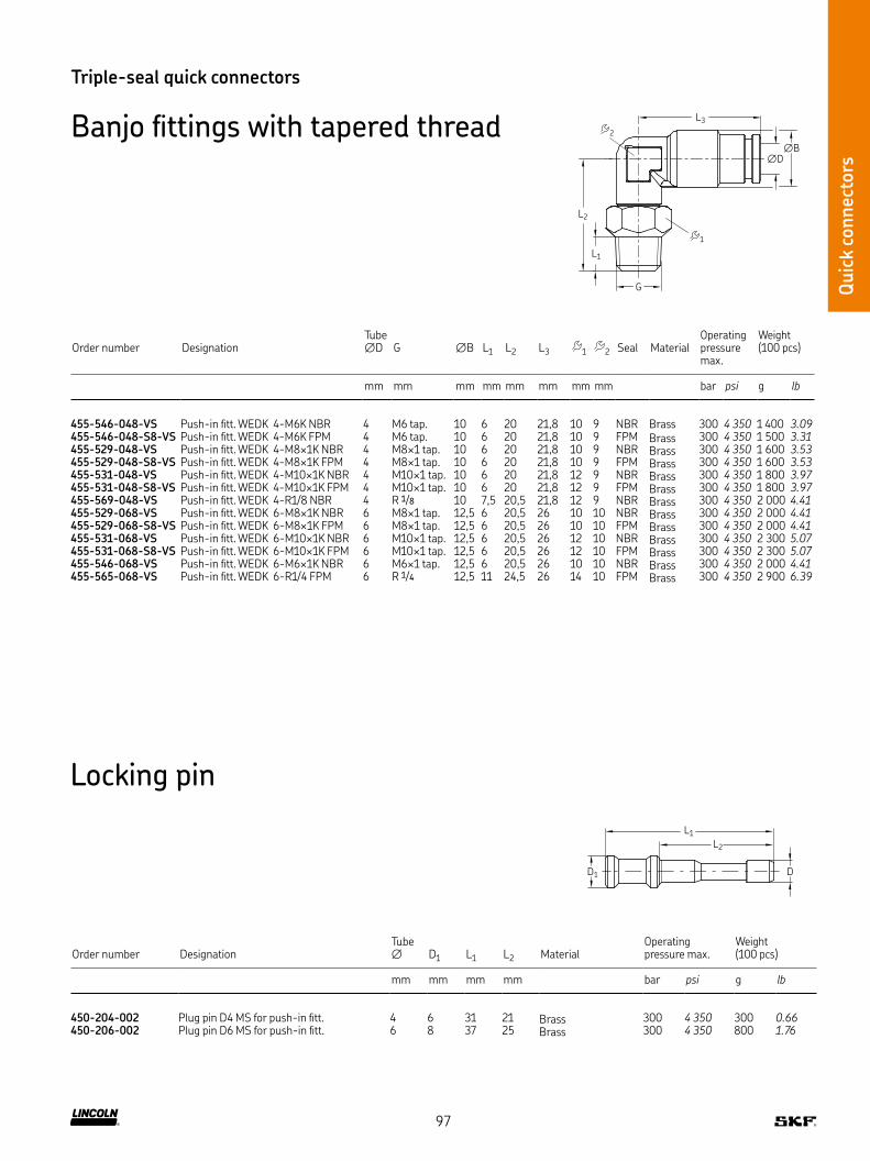
Quic
k co
nnec
tors
Triple-seal quick connectors
Banjo fittings with tapered threadL3
G
∅D
∅B
L2
L1
2
1
Order number DesignationTube ∅D G ∅B L1 L2 L3 1 2 Seal Material
Operating pressure max
Weight (100 pcs)
mm mm mm mm mm mm mm mm bar psi g lb
455-546-048-VS Push-in fitt WEDK 4-M6K NBR 4 M6 tap 10 6 20 21,8 10 9 NBR Brass 300 4 350 1 400 3.09455-546-048-S8-VS Push-in fitt WEDK 4-M6K FPM 4 M6 tap 10 6 20 21,8 10 9 FPM Brass 300 4 350 1 500 3.31455-529-048-VS Push-in fitt WEDK 4-M8×1K NBR 4 M8×1 tap 10 6 20 21,8 10 9 NBR Brass 300 4 350 1 600 3.53455-529-048-S8-VS Push-in fitt WEDK 4-M8×1K FPM 4 M8×1 tap 10 6 20 21,8 10 9 FPM Brass 300 4 350 1 600 3.53455-531-048-VS Push-in fitt WEDK 4-M10×1K NBR 4 M10×1 tap 10 6 20 21,8 12 9 NBR Brass 300 4 350 1 800 3.97455-531-048-S8-VS Push-in fitt WEDK 4-M10×1K FPM 4 M10×1 tap 10 6 20 21,8 12 9 FPM Brass 300 4 350 1 800 3.97455-569-048-VS Push-in fitt WEDK 4-R1/8 NBR 4 R 1/8 10 7,5 20,5 21,8 12 9 NBR Brass 300 4 350 2 000 4.41455-529-068-VS Push-in fitt WEDK 6-M8×1K NBR 6 M8×1 tap 12,5 6 20,5 26 10 10 NBR Brass 300 4 350 2 000 4.41455-529-068-S8-VS Push-in fitt WEDK 6-M8×1K FPM 6 M8×1 tap 12,5 6 20,5 26 10 10 FPM Brass 300 4 350 2 000 4.41455-531-068-VS Push-in fitt WEDK 6-M10×1K NBR 6 M10×1 tap 12,5 6 20,5 26 12 10 NBR Brass 300 4 350 2 300 5.07455-531-068-S8-VS Push-in fitt WEDK 6-M10×1K FPM 6 M10×1 tap 12,5 6 20,5 26 12 10 FPM Brass 300 4 350 2 300 5.07455-546-068-VS Push-in fitt WEDK 6-M6×1K NBR 6 M6×1 tap 12,5 6 20,5 26 10 10 NBR Brass 300 4 350 2 000 4.41455-565-068-VS Push-in fitt WEDK 6-R1/4 FPM 6 R 1/4 12,5 11 24,5 26 14 10 FPM Brass 300 4 350 2 900 6.39
Locking pin
Order number DesignationTube ∅ D1 L1 L2 Material
Operating pressure max
Weight (100 pcs)
mm mm mm mm bar psi g lb
450-204-002 Plug pin D4 MS for push-in fitt 4 6 31 21 Brass 300 4 350 300 0.66450-206-002 Plug pin D6 MS for push-in fitt 6 8 37 25 Brass 300 4 350 800 1.76
L1
L2
D1 D
97
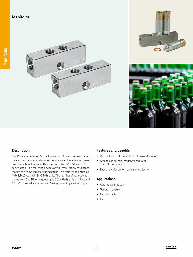
Manifolds
Description
Manifolds are designed for the installation of one or several metering
devices, restrictors or lubrication point lines and enable direct main
line connection They are often used with the 341, 351 and 361
series single-line metering devices or VD screw-in flow restrictors
Manifolds are available for various main-line connections, such as
M8×1, M10×1 and M14×1 5 threads The number of outlet ports
varies from 1 to 10 (on request up to 20) with threads of M8×1 and
M10×1 The seal is made via an O-ring or sealing washer (copper)
Features and benefits
• Wide selection of connection options and variants
• Available in aluminum; galvanized steel available on request
• Easy and quick system extension/reduction
Applications
• Automotive Industry
• General industry
• Machine tools
• Etc
Manifold
s
98
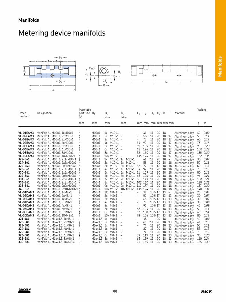
Manifold
s
Order number
DesignationMain tube port tube ∅
D1 D2
above
D3
below
L1 L2 H1 H2 B T MaterialWeight
mm mm mm mm mm mm mm mm mm mm g lb
VL-01EAM3 Manifold AL M10×1, 1xM10×1 6 M10×1 1x M10×1 – – 41 11 20 18 – Aluminum alloy 40 0.09VL-02EAM3 Manifold AL M10×1, 2xM10×1 6 M10×1 2x M10×1 – – 58 11 20 18 17 Aluminum alloy 50 0.11VL-03EAM3 Manifold AL M10×1, 3xM10×1 6 M10×1 3x M10×1 – – 75 11 20 18 17 Aluminum alloy 60 0.13VL-04EAM3 Manifold AL M10×1, 4xM10×1 6 M10×1 4x M10×1 – 34 92 11 20 18 17 Aluminum alloy 78 0.17VL-05EAM3 Manifold AL M10×1, 5xM10×1 6 M10×1 5x M10×1 – 51 109 11 20 18 17 Aluminum alloy 90 0.20VL-06EAM3 Manifold AL M10×1, 6xM10×1 6 M10×1 6x M10×1 – 68 126 11 20 18 17 Aluminum alloy 100 0.22VL-08EAM3 Manifold AL M10×1, 8xM10×1 6 M10×1 8x M10×1 – 52 160 11 20 18 17 Aluminum alloy 135 0.30VL-10EAM3 Manifold AL M10×1, 10xM10×1 6 M10×1 10x M10×1 – 136 194 11 20 18 17 Aluminum alloy 162 0.36322-861 Manifold AL M10×1, 2x1xM10×1 6 M10×1 1x M10×1 1x M10×1 41 11 20 18 – Aluminum alloy 30 0.07324-861 Manifold AL M10×1, 2x2xM10×1 6 M10×1 2x M10×1 2x M10×1 – 58 11 20 18 18 Aluminum alloy 50 0.11326-663 Manifold AL M10×1, 2x3xM10×1 6 M10×1 3x M10×1 3x M10×1 52 77 11 17 18 18 Aluminum alloy 60 0.13328-861 Manifold AL M10×1, 2x4xM10×1 6 M10×1 4x M10×1 4x M10×1 34 92 11 20 18 18 Aluminum alloy 70 0.15330-861 Manifold AL M10×1, 2x5xM10×1 6 M10×1 5x M10×1 5x M10×1 51 109 11 20 18 18 Aluminum alloy 80 0.18332-861 Manifold AL M10×1, 2x6xM10×1 6 M10×1 6x M10×1 6x M10×1 68 126 11 20 18 18 Aluminum alloy 96 0.21334-861 Manifold AL M10×1, 2x7xM10×1 6 M10×1 7x M10×1 7x M10×1 85 143 11 20 18 18 Aluminum alloy 108 0.24336-861 Manifold AL M10×1, 2x8xM10×1 6 M10×1 8x M10×1 8x M10×1 102 160 11 20 18 18 Aluminum alloy 128 0.28338-861 Manifold AL M10×1, 2x9xM10×1 6 M10×1 9x M10×1 9x M10×1 119 177 11 20 18 18 Aluminum alloy 137 0.30340-861 Manifold AL M10×1, 2x10xM10×1 6 M10×1 10x M10×1 10x M10×1 136 194 11 20 18 18 Aluminum alloy 140 0.31VL-01DAM3 Manifold AL M10×1, 1xM8×1 6 M10×1 1X M8×1 – – 39 10,5 17 13 – Aluminum alloy 20 0.04VL-02DAM3 Manifold AL M10×1, 2xM8×1 6 M10×1 2x M8×1 – – 52 10,5 17 13 13 Aluminum alloy 30 0.07VL-03DAM3 Manifold AL M10×1, 1xM8×1 6 M10×1 3x M8×1 – – 65 10,5 17 13 13 Aluminum alloy 30 0.07VL-04DAM3 Manifold AL M10×1, 3xM8×1 6 M10×1 4x M8×1 – – 78 10,5 17 13 13 Aluminum alloy 38 0.08VL-05DAM3 Manifold AL M10×1, 4xM8×1 6 M10×1 5x M8×1 – – 91 10,5 17 13 13 Aluminum alloy 40 0.09VL-06DAM3 Manifold AL M10×1, 6xM8×1 6 M10×1 6x M8×1 – 52 104 11 20 18 13 Aluminum alloy 50 0.11VL-08DAM3 Manifold AL M10×1, 8xM8×1 6 M10×1 8x M8×1 – 52 130 10,5 17 13 13 Aluminum alloy 65 0.14VL-10DAM3 Manifold AL M10×1, 10xM8×1 6 M10×1 10x M8×1 – 78 156 10,5 17 13 13 Aluminum alloy 80 0.18321-581 Manifold AL M14×1 5, 1xM8×1 8 M14×1,5 1x M8×1 – – 48 20 18 – Aluminum alloy 40 0.09322-581 Manifold AL M14×1 5, 2xM8×1 8 M14×1,5 2x M8×1 – – 61 11 20 18 13 Aluminum alloy 47 0.10323-581 Manifold AL M14×1 5, 3xM8×1 8 M14×1,5 3x M8×1 – – 74 11 20 18 13 Aluminum alloy 50 0.11324-581 Manifold AL M14×1 5, 4xM8×1 8 M14×1,5 4x M8×1 – – 87 11 20 18 13 Aluminum alloy 55 0.12325-581 Manifold AL M14×1 5, 5xM8×1 8 M14×1,5 5x M8×1 – 74 11 20 18 13 Aluminum alloy 70 0.15326-581 Manifold AL M14×1 5, 6xM8×1 8 M14×1,5 6x M8×1 – 39 113 11 20 18 13 Aluminum alloy 90 0.20328-581 Manifold AL M14×1 5, 8xM8×1 8 M14×1,5 8x M8×1 – 65 139 11 20 18 13 Aluminum alloy 110 0.24330-581 Manifold AL M14×1 5, 10xM8×1 8 M14×1,5 10x M8×1 – 91 165 11 20 18 13 Aluminum alloy 135 0.30
Manifolds
Metering device manifolds
D3
L2
2.8
B
L1=
D2
= T T =
D1
4
∅4.3
H1 ∅7.4
H2
=
==
99

Tubes and hoses
Tubes
and h
ose
s
Description
Pipe and hose lines are an important connecting element in all
lubrication systems The lubricant is transported by them from
the pump via the metering device to the lubrication points
The following chapter lists the suitable pipe and hose material
for all SKF lubrication systems
This criteria must be considered when selecting:
• Pipe dimension (inside diameter and wall thickness): Selection according to the occurring pressures and pressure drops
• Material or surface protection of the steel pipes
Material for steel pipes: precision hydraulic pipe seamless to
EN 10305-4 in galvanized Cr-6-free or stainless steel material
1 4571 for aggressive conditions (sea water, cleaning agents, paper
machines)
Material for plastic pipes Polyamide: PA12H (natural, semi-rigid)
PA12HL (black, semi-rigid), PA12PH (natural, flexible), PA12PHL
(black, flexible)
Features and benefits
• Reliable and long-term lubricant transfer solutions for low-, medium- and high-pressure lubrication systems
• Quick installation as pipes/hoses are prefilled with lubricant
• Wide range of available versions
Applications
• Paper and packaging industry
• Food and beverage industry
• Construction machines
• Agriculture machines
• Oil and gas industry
• Renewable energy
• Material handling
• On-road trucks
• Etc
100
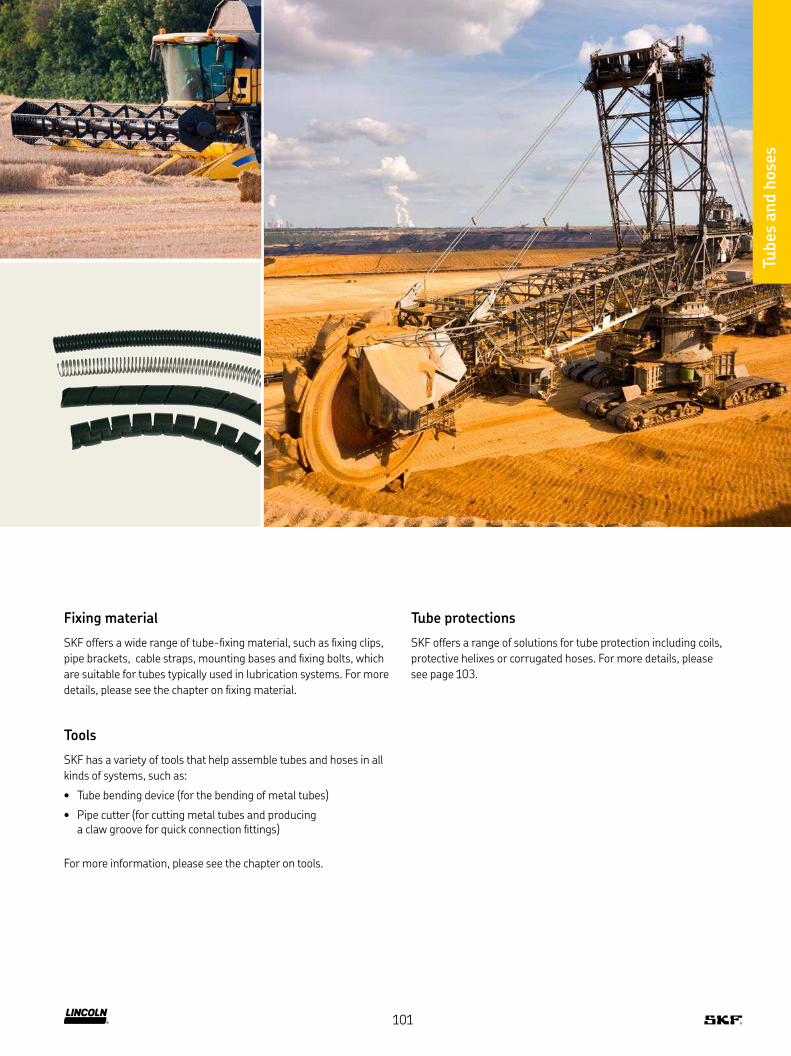
Fixing material
SKF offers a wide range of tube-fixing material, such as fixing clips,
pipe brackets, cable straps, mounting bases and fixing bolts, which
are suitable for tubes typically used in lubrication systems For more
details, please see the chapter on fixing material
Tools
SKF has a variety of tools that help assemble tubes and hoses in all
kinds of systems, such as:
• Tube bending device (for the bending of metal tubes)
• Pipe cutter (for cutting metal tubes and producing a claw groove for quick connection fittings)
For more information, please see the chapter on tools
Tube protections
SKF offers a range of solutions for tube protection including coils,
protective helixes or corrugated hoses For more details, please
see page 103
Tubes
and h
ose
s
101

Tubes
and h
ose
s
Tubes and hoses
Plastic tubing
S
∅D
∅D1
Order number Designation
Tube outside ∅D
Wall thickness S
Min bending radius 1) R
Operating pressuremax at 20°C / 68°F Material
Weight (100 m)
mm mm mm bar psi kg lb
Plastic tubing semirigid (without plasticizer)WVN715-RO2 5X0 5 TUBE, PA12H 2 5X0 5 NATUR 2,5 0,5 25 66 957 PA12H 0,33 0.73WVN715-RO4X0 85 TUBE, PA12H 4 0X0 85 NATUR 4 0,85 38 72 1 044 PA12H 0,88 1.94WVN715RO4X0 85+A89 TUBE, PA12HL 4 0X0 85 BLACK 4 0,85 38 72 1 044 PA12HL 0,88 1.94112-35127-7 TUBE, PA12HL 4 0X1 0 BLACK 4 1 30 80 1 160 PA12HL 0,9 1.98112-35127-5 TUBE, PA12HL 4 0X 1 0 NATUR 4 1 30 80 1 160 PA12HL 0,9 1.98WVN715-RO6X1 TUBE, PA12H 6 0X1 0 NATUR 6 1 63 53 768 PA12H 1,61 3.55WVN715-RO6X1 25 TUBE, PA12H 6 0X1 25 NATUR 6 1,25 63 70 1 015 PA12H 1,92 4.23WVN715RO6X1 25+A89 TUBE, PA12HL 6 0X1 25 BLACK 6 1,25 63 70 1 015 PA12HL 2,16 4.76112-35127-2 TUBE, PA12HL 6 0X1 5 BLACK 6 1,5 40 89 1 290 PA12HL 2,29 5.05WVN715-RO8x1 25 TUBE, PA12H 8 0X1 25 NATUR 8 1,25 76 49 710 PA12H 2,73 6.02
Plastic tubing flexible (containing plasticizer)WVN716-RO4X0 85 TUBE, PA12PH 4 0X 0 85 NATUR 4 0,85 38 36 522 PA12PH 0,53 1.17WVN716RO4X0 85+A89 TUBE, PA12PHL 4 0X 0 85 BLACK 4 0,85 38 36 522 PA12PHL 0,53 1.17112-35225-4 TUBE, PA12PHL 4 0X 1 0 BLACK 4 1 27 40 580 PA12PHL 0,63 1.39WVN716-RO6X1 25 TUBE, PA12PH 6 0X1 25 NATUR 6 1,25 63 35 507 PA12PH 2 4.41WVN716RO6X1 25+A89 TUBE, PA12PHL 6 0X1 25 BLACK 6 1,25 63 35 507 PA12PHL 2 4.41WVN716-RO8X1 25 TUBE, PA12PH 8 0X1 25 NATUR 8 1,25 80 25 362 PA12PH 2,8 6.17
1) without bending device2) the permissible burst pressure is lower at higher temperatures (→ pressure utilization factor table)
Pressure utilization factor
Temperature up to Pressure efficiency
°C %
23 10030 8340 7250 6460 5770 5280 47
The pressure utilization factor indicates the percentage utilization of effective stress available in the specified temperature ranges, based on 23 °C
Technical Data
Material PA 12 H polyamide 12, semirigid, unplasticized as per DIN 73378, stabilized against heat and aging
PA 12 HL (black tubing) polyamide 12, semirigid, unplasticized as per DIN 73378, stabilized against light, heat and aging
PA 12 PH polyamide 12, flexible, containing plasticizer as per DIN 73378, stabilized against heat and aging
PA 12 PHL (black tubing) polyamide 12, flexible, containing plasticizer as per DIN 73378, stabilized against light, heat, and aging
Temperature range
–60 to +80 °C –60 to +80 °C
102

Tubes
and h
ose
s
Tubes and hoses
Tube protections
Order number Designation ∅ Material Weight
mm g lb
Corrugated tupe 982-760-120 TUBE, CORRUGATED PA6 NW8 8,4 Polyamide 6, black colour 20 0.04982-760-130 TUBE, CORRUGATED PA6 NW10 10 Polyamide 6, black colour 26 0.06982-760-160 TUBE, CORRUGATED PA6 NW12 12,3 Polyamide 6, black colour 34 0.07
Spring coil982-760-122 SPRING COIL DI6 1XD1 2 1 4310 6,1 Stainless steel 64 0.14982-760-132 SPRING COIL DI10 6XD1 2 1 4310 10,6 Stainless steel 64 0.14982-760-142 SPRING COIL DI13 5XD1 5 1 4310 12,5 Stainless steel 64 0.14111-35306-5 SPRING COIL DI17XD1 8 1 4310 17 Stainless steel 290 0.64
Plastic helix113-35075-2 PLASTIC HELIX GR 6 BLACK 5–20 Polyethylene, black colour 13 0.03113-35075-3 PLASTIC HELIX GR 12 BLACK 9–30 Polyethylene, black colour 48 0.11
Spiral hose982-760-102 SPIRAL HOSE, PP NW8 SLOTTED 6–9 Polypropylene 25 0.06982-760-172 SPIRAL HOSE, PP NW15 SLOTTED 10–16 Polypropylene 100 0.22
Corrugated tupe
Spring coil
Plastic helix
Spiral hose
103
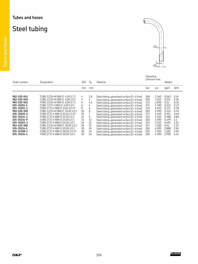
Tubes
and h
ose
s
Order number Designation ∅D D1 Material
Operating pressure max
Weight
mm mm bar psi kg/m lb/m
982-120-041 TUBE, E235+N NBK D 4,0X 0,7 C 4 2,6 Steel tubing, galvanized surface (Cr-6 free) 368 5 340 0,063 0.14982-120-040 TUBE, E235+N NBK D 4,0X 1,0 C 4 2 Steel tubing, galvanized surface (Cr-6 free) 500 7 250 0,074 0.16982-120-061 TUBE, E235+N NBK D 6,0X 0,7 C 6 4,6 Steel tubing, galvanized surface (Cr-6 free) 333 4 830 0,12 0.26105-35251-1 TUBE, ST37 4 NBK D 6,0X 1,0 C 6 4 Steel tubing, galvanized surface (Cr-6 free) 372 5 390 0,123 0.27105-35251-3 TUBE,ST37 4 NBK D 8,0X 1,0 CF 8 6 Steel tubing, galvanized surface (Cr-6 free) 333 4 830 0,173 0.38982-120-100 TUBE, E235+N NBK D 10,0X 1,0 C 10 8 Steel tubing, galvanized surface (Cr-6 free) 282 4 090 0,222 0.49105-35025-5 TUBE,ST37 4 NBK D 10,0x 1 5 CF 10 7 Steel tubing, galvanized surface (Cr-6 free) 373 5 410 0,314 0.69105-35134-3 TUBE,ST37 4 NBK D 12,0X 1,5 C 12 9 Steel tubing, galvanized surface (Cr-6 free) 353 5 120 0,388 0.86105-35134-9 TUBE,ST37 4 NBK D 15,0X 1,5 C 15 12 Steel tubing, galvanized surface (Cr-6 free) 282 4 090 0,499 1.1105-35183-3 TUBE,ST37 4 NBK D 16,0X 2,0 C 16 12 Steel tubing, galvanized surface (Cr-6 free) 353 5 120 0,691 1.52982-120-180 TUBE, E235+N NBK D 18,0X 1,0 C 18 15 Steel tubing, galvanized surface (Cr-6 free) 157 2 280 0,61 1.35105-35134-1 TUBE,ST37 4 NBK D 20,0X 2,0 C 20 16 Steel tubing, galvanized surface (Cr-6 free) 282 4 090 0,888 1.96105-35308-1 TUBE,ST37 4 NBK D 28,0X 2,0 CF 28 24 Steel tubing, galvanized surface (Cr-6 free) 201 2 910 1,282 2.83105-35134-4 TUBE,ST37 4 NBK D 30,0X 3,0 C 30 24 Steel tubing, galvanized surface (Cr-6 free) 282 4 090 1,998 4.41
Tubes and hoses
Steel tubing
S
∅D
∅D1
104
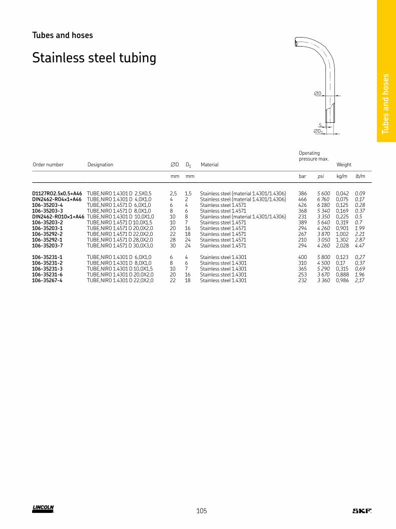
Tubes
and h
ose
s
Order number Designation ∅D D1 Material
Operating pressure max
Weight
mm mm bar psi kg/m lb/m
D1127RO2 5x0 5+A46 TUBE,NIRO 1 4301 D 2,5X0,5 2,5 1,5 Stainless steel (material 1 4301/1 4306) 386 5 600 0,042 0.09DIN2462-RO4×1+A46 TUBE,NIRO 1 4301 D 4,0X1,0 4 2 Stainless steel (material 1 4301/1 4306) 466 6 760 0,075 0.17106-35203-4 TUBE,NIRO 1 4571 D 6,0X1,0 6 4 Stainless steel 1 4571 426 6 180 0,125 0.28106-35203-3 TUBE,NIRO 1 4571 D 8,0X1,0 8 6 Stainless steel 1 4571 368 5 340 0,169 0.37DIN2462-RO10×1+A46 TUBE,NIRO 1 4301 D 10,0X1,0 10 8 Stainless steel (material 1 4301/1 4306) 231 3 350 0,225 0.5106-35203-2 TUBE,NIRO 1 4571 D 10,0X1,5 10 7 Stainless steel 1 4571 389 5 640 0,319 0.7106-35203-1 TUBE,NIRO 1 4571 D 20,0X2,0 20 16 Stainless steel 1 4571 294 4 260 0,901 1.99106-35292-2 TUBE,NIRO 1 4571 D 22,0X2,0 22 18 Stainless steel 1 4571 267 3 870 1,002 2.21106-35292-1 TUBE,NIRO 1 4571 D 28,0X2,0 28 24 Stainless steel 1 4571 210 3 050 1,302 2.87106-35203-7 TUBE,NIRO 1 4571 D 30,0X3,0 30 24 Stainless steel 1 4571 294 4 260 2,028 4.47
106-35231-1 TUBE,NIRO 1 4301 D 6,0X1,0 6 4 Stainless steel 1 4301 400 5 800 0,123 0,27106-35231-2 TUBE,NIRO 1 4301 D 8,0X1,0 8 6 Stainless steel 1 4301 310 4 500 0,17 0,37106-35231-3 TUBE,NIRO 1 4301 D 10,0X1,5 10 7 Stainless steel 1 4301 365 5 290 0,315 0,69106-35231-6 TUBE,NIRO 1 4301 D 20,0X2,0 20 16 Stainless steel 1 4301 253 3 670 0,888 1,96106-35267-4 TUBE,NIRO 1 4301 D 22,0X2,0 22 18 Stainless steel 1 4301 232 3 360 0,986 2,17
Tubes and hoses
Stainless steel tubing
S
∅D
∅D1
105

Tubes
and h
ose
s
Tubes and hoses
Low-pressure hoses for main lines max. 45 bar
30
Rmin = 2.5xD2
30
D1
D2
∅D
Order number Designation 1)Tube ∅D Length
Rubber∅D1
Metal braided D2
Max increase in volume at 80 bar Weight
mm mm mm mm cm3/m g lb
Low-pressure hoses with tube stud ∅4 mm714-180 HOSE CR 45 DN3X 180,STU 4 4 180 11 – 2,5 39 0.09714-220 HOSE CR 45 DN3X 220,STU 4 4 220 11 – 2,5 43 0.09714-260 HOSE CR 45 DN3X 260,STU 4 4 260 11 – 2,5 48 0.11714-300 HOSE CR 45 DN3X 300,STU 4 4 300 11 – 2,5 57 0.13714-380 HOSE CR 45 DN3X 380,STU 4 4 380 11 – 2,5 61 0.13714-420 HOSE CR 45 DN3X 420,STU 4 4 420 11 – 2,5 70 0.15714-450 HOSE CR 45 DN3X 450,STU 4 4 450 11 – 2,5 74 0.16714-500 HOSE CR 45 DN3X 500,STU 4 4 500 11 – 2,5 84 0.19714-580 HOSE CR 45 DN3X 580,STU 4 4 580 11 – 2,5 92 0.20
Low-pressure hoses with tube stud ∅4 mm and metal braid714-180-M HOSE CR 45 DN3X 180,STU 4, MET BRAID 4 180 11 12 2,5 56 0.12714-260-M HOSE CR 45 DN3X 260,STU 4, MET BRAID 4 260 11 12 2,5 69 0.15714-300-M HOSE CR 45 DN3X 300,STU 4, MET BRAID 4 300 11 12 2,5 75 0.17714-400-M HOSE CR 45 DN3X 400,STU 4, MET BRAID 4 400 11 12 2,5 97 0.21714-500-M HOSE CR 45 DN3X 500,STU 4, MET BRAID 4 500 11 12 2,5 119 0.26714-580-M HOSE CR 45 DN3X 580,STU 4, MET BRAID 4 580 11 12 2,5 167 0.37
Low-pressure hoses with tube stud ∅6 mm716-220 HOSE CR 45 DN4,5X 220,STU 6 6 220 13 – 3,6 64 0.14716-300 HOSE CR 45 DN4,5X 300,STU 6 6 300 13 – 3,6 72 0.16716-340 HOSE CR 45 DN4,5X 340,STU 6 6 340 13 – 3,6 79 0.17716-380 HOSE CR 45 DN4,5X 380,STU 6 6 380 13 – 3,6 86 0.19716-420 HOSE CR 45 DN4,5X 420,STU 6 6 420 13 – 3,6 90 0.20716-500 HOSE CR 45 DN4,5X 500,STU 6 6 500 13 – 3,6 101 0.22716-580 HOSE CR 45 DN4,5X 580,STU 6 6 580 13 – 3,6 128 0.28
Low-pressure hoses with tube stud ∅6 mm and metal braid716-300-M HOSE CR 45 DN4,5X 300,STU6 MET BRAID 6 300 13 14 3,6 108 0.24716-400-M HOSE CR 45 DN4,5X 400,STU6 MET BRAID 6 400 13 14 3,6 140 0.31716-460-M HOSE CR 45 DN4,5X 500,STU6 MET BRAID 6 450 13 14 3,6 155 0.34716-500-M HOSE CR 45 DN4,5X 580,STU6 MET BRAID 6 500 13 14 3,6 165 0.36
Low-pressure hoses with tube stud ∅8 mm718-340 HOSE CR 45 DN6,5X 340,STU 8 8 340 15 – 4,4 117 0.26718-450 HOSE CR 45 DN6,5X 450,STU 8 8 450 15 – 4,4 133 0.29718-580 HOSE CR 45 DN6,5X 580,STU 8 8 580 15 – 4,4 141 0.31
Low-pressure hoses with tube stud ∅8 mm and metal braid718-400-M HOSE CR 45 DN6,5X 400,STU 8, MET BRAID 8 400 15 16 4,4 136 0.30718-450-M HOSE CR 45 DN6,5X 450,STU 8, MET BRAID 8 450 15 16 4,4 157 0.35718-500-M HOSE CR 45 DN6,5X 500,STU 8, MET BRAID 8 500 15 16 4,4 174 0.38
1) Material hose: mineral oil resistant CR rubber inside; 2 layers of braided rayon, outside rubber conditionally oil resistant, resistant to light cracks and ozone Material metal braid: galvanized steel wire; tube ends: galvanized steel tubing
106

Tubes
and h
ose
s
Tubes and hoses
Low-pressure hoses for main lines max. 45 bar with tapered sleeve and socket union on both ends
Order number Designation 1)Tube ∅D Length
Rubber∅D1
Metal braided D2
Thread D3
Max increase in volume at 80 bar Weight
mm mm mm mm mm cm3/m g lb
Low-pressure hoses with tapered sleeve socket union714-180-K HOSE CR 45 DN3X 180,M8X1 4 180 11 – M8×1 2,5 45 0.10714-220-K HOSE CR 45 DN3X 220,M8X1 4 220 11 – M8×1 2,5 49 0.11714-260-K HOSE CR 45 DN3X 260,M8X1 4 260 11 – M8×1 2,5 53 0.12714-300-K HOSE CR 45 DN3X 300,M8X1 4 300 11 – M8×1 2,5 59 0.13714-380-K HOSE CR 45 DN3X 380,M8X1 4 380 11 – M8×1 2,5 68 0.15714-420-K HOSE CR 45 DN3X 420,M8X1 4 420 11 – M8×1 2,5 76 0.17714-450-K HOSE CR 45 DN3X 450,M8X1 4 450 11 – M8×1 2,5 84 0.19714-500-K HOSE CR 45 DN3X 500,M8X1 4 500 11 – M8×1 2,5 90 0.20714-580-K HOSE CR 45 DN3X 580,M8X1 4 580 11 – M8×1 2,5 100 0.22
Low-pressure hoses with tapered sleeve socket union and metal braid714-180-MK HOSE CR 45 DN3X 180,M8X1, MET BRAID 4 180 11 12 M8×1 2,5 63 0.14714-260-MK HOSE CR 45 DN3X 260,M8X1, MET BRAID 4 260 11 12 M8×1 2,5 80 0.18714-300-MK HOSE CR 45 DN3X 300,M8X1, MET BRAID 4 300 11 12 M8×1 2,5 85 0.19714-400-MK HOSE CR 45 DN3X 400,M8X1, MET BRAID 4 400 11 12 M8×1 2,5 110 0.24714-500-MK HOSE CR 45 DN3X 500,M8X1, MET BRAID 4 500 11 12 M8×1 2,5 120 0.26714-580-MK HOSE CR 45 DN3X 580,M8X1, MET BRAID 4 580 11 12 M8×1 2,5 140 0.31
Low-pressure hoses with tapered sleeve socket union716-220-K HOSE CR 45 DN4,5X 220,M10X1 6 220 13 – M10×1 3,6 68 0.15716-300-K HOSE CR 45 DN4,5X 300,M10X1 6 300 13 – M10×1 3,6 80 0.18716-340-K HOSE CR 45 DN4,5X 340,M10X1 6 340 13 – M10×1 3,6 85 0.19716-380-K HOSE CR 45 DN4,5X 380,M10X1 6 380 13 – M10×1 3,6 92 0.20716-420-K HOSE CR 45 DN4,5X 420,M10X1 6 420 13 – M10×1 3,6 98 0.22716-500-K HOSE CR 45 DN4,5X 500,M10X1 6 500 13 – M10×1 3,6 113 0.25716-580-K HOSE CR 45 DN4,5X 580,M10X1 6 580 13 – M10×1 3,6 127 0.28
Low-pressure hoses with tapered sleeve socket union and metal braid716-300-MK HOSE CR 45 DN4,5X 300,M10X1, MET BRAID 6 300 13 14 M10×1 3,6 110 0.24716-400-MK HOSE CR 45 DN4,5X 400,M10X1, MET BRAID 6 400 13 14 M10×1 3,6 140 0.31716-450-MK HOSE CR 45 DN4,5X 500,M10X1, MET BRAID 6 450 13 14 M10×1 3,6 160 0.35716-500-MK HOSE CR 45 DN4,5X 580,M10X1, MET BRAID 6 500 13 14 M10×1 3,6 180 0.40
Low-pressure hoses with tapered sleeve socket union718-340-K HOSE CR 45 DN6,5X 400,M14X1,5 8 340 15 – M14×1,5 4,4 116 0.26718-450-K HOSE CR 45 DN6,5X 450,M14X1,5 8 450 15 – M14×1,5 4,4 147 0.32718-580-K HOSE CR 45 DN6,5X 500,M14X1,5 8 580 15 – M14×1,5 4,4 164 0.36
Low-pressure hoses with tapered sleeve socket union and metal braid718-400-MK HOSE CR 45 DN6,5X 400,M14X1,5, MET BRAID 8 400 15 16 M14×1,5 4,4 160 0.35718-450-MK HOSE CR 45 DN6,5X 450,M14X1,5, MET BRAID 8 450 15 16 M14×1,5 4,4 195 0.43718-500-MK HOSE CR 45 DN6,5X 500,M14X1,5, MET BRAID 8 500 15 16 M14×1,5 4,4 221 0.49
30
Rmin = 2.5xD2
D3
30
D1
D2
∅D
1) Material hose: mineral oil resistant CR rubber inside; 2 layers of braided rayon, outside rubber conditionally oil resistant, resistant to light cracks and ozone Material metal braid: galvanized steel wire; tube ends: galvanized steel tubing
107

Tubes
and h
ose
s
Tubes and hoses
Low-pressure hoses for main lines max. 45 bar with socket union on both ends and with claw groove for quick connectors
Order number Designation 1)Tube ∅D Length
Rubber∅D1
Metal braided D2
Max increase in volume at 80 bar Weight
mm mm mm mm cm3/m g lb
Low-pressure hoses with tube stud ∅4 mm with claw groove for quick connectors714-180-VS HOSE CR 45 DN3X 180,VS 4 180 11 – 2,5 39 0.09714-220-VS HOSE CR 45 DN3X 220,VS 4 220 11 – 2,5 43 0.09714-260-VS HOSE CR 45 DN3X 260,VS 4 260 11 – 2,5 48 0.11714-300-VS HOSE CR 45 DN3X 300,VS 4 300 11 – 2,5 57 0.13714-380-VS HOSE CR 45 DN3X 380,VS 4 380 11 – 2,5 61 0.13714-420-VS HOSE CR 45 DN3X 420,VS 4 420 11 – 2,5 70 0.15714-450-VS HOSE CR 45 DN3X 450,VS 4 450 11 – 2,5 74 0.16714-500-VS HOSE CR 45 DN3X 500,VS 4 500 11 – 2,5 84 0.19714-580-VS HOSE CR 45 DN3X 580,VS 4 580 11 – 2,5 92 0.20
Low-pressure hoses with tube stud ∅4 mm with claw groove for quick connectors and metal braid714-180-M-VS HOSE CR 45 DN3X 180,VS, MET BRAID 4 180 11 12 2,5 56 0.12714-260-M-VS HOSE CR 45 DN3X 260,VS, MET BRAID 4 260 11 12 2,5 69 0.15714-300-M-VS HOSE CR 45 DN3X 300,VS, MET BRAID 4 300 11 12 2,5 75 0.17714-400-M-VS HOSE CR 45 DN3X 400,VS, MET BRAID 4 400 11 12 2,5 97 0.21714-500-M-VS HOSE CR 45 DN3X 500,VS, MET BRAID 4 500 11 12 2,5 119 0.26714-580-M-VS HOSE CR 45 DN3X 580,VS, MET BRAID 4 580 11 12 2,5 167 0.37
Low-pressure hoses with tube stud ∅6 mm with claw groove for quick connectors716-220-VS HOSE CR 45 DN4,5X 220,VS 6 220 13 – 3,6 64 0.14716-300-VS HOSE CR 45 DN4,5X 300,VS 6 300 13 – 3,6 72 0.16716-340-VS HOSE CR 45 DN4,5X 340,VS 6 340 13 – 3,6 79 0.17716-380-VS HOSE CR 45 DN4,5X 380,VS 6 380 13 – 3,6 86 0.19716-420-VS HOSE CR 45 DN4,5X 420,VS 6 420 13 – 3,6 90 0.20716-500-VS HOSE CR 45 DN4,5X 500,VS 6 500 13 – 3,6 101 0.22716-580-VS HOSE CR 45 DN4,5X 580,VS 6 580 13 – 3,6 128 0.28
Low-pressure hoses with tube stud ∅6 mm with claw groove for quick connectors and metal braid716-300-M-VS HOSE CR 45 DN4,5X 300,VS, MET BRAID 6 300 13 14 3,6 108 0.24716-400-M-VS HOSE CR 45 DN4,5X 400,VS, MET BRAID 6 400 13 14 3,6 140 0.31716-450-M-VS HOSE CR 45 DN4,5X 500,VS, MET BRAID 6 450 13 14 3,6 155 0.34716-500-M-VS HOSE CR 45 DN4,5X 580,VS, MET BRAID 6 500 13 14 3,6 165 0.36
Low-pressure hoses with tube stud ∅8 mm with claw groove for quick connectors718-340-VS HOSE CR 45 DN6,5X 340,VS 8 340 15 – 4,4 117 0.26718-450-VS HOSE CR 45 DN6,5X 450,VS 8 450 15 – 4,4 133 0.29718-580-VS HOSE CR 45 DN6,5X 580,VS 8 580 15 – 4,4 141 0.31
Low-pressure hoses with tube stud ∅8 mm with claw groove for quick connectors and metal braid718-400-M-VS HOSE CR 45 DN6,5X 400,VS, MET BRAID 8 400 15 16 4,4 136 0.30718-450-M-VS HOSE CR 45 DN6,5X 450,VS, MET BRAID 8 450 15 16 4,4 157 0.35718-500-M-VS HOSE CR 45 DN6,5X 500,VS, MET BRAID 8 500 15 16 4,4 174 0.38
1) Material hose: mineral oil resistant CR rubber inside; 2 layers of braided rayon, outside rubber conditionally oil resistant, resistant to light cracks and ozone Material metal braid: galvanized steel wire; tube ends: galvanized steel tubing
30
Rmin = 2.5xD2
30
D1
D2
∅D
108

Tubes
and h
ose
s
Tubes and hoses
Low-pressure hoses for secondary lines max. 15 bar
Order number Designation 1)Tube ∅D Length
Rubber∅D1 Weight
mm mm mm g lb
734-180 HOSE CR 15 DN3X 180,STU 4 4 180 8,8 30 0,07734-220 HOSE CR 15 DN3X 220,STU 4 4 220 8,8 33 0,07734-260 HOSE CR 15 DN3X 260,STU 4 4 260 8,8 37 0,08734-300 HOSE CR 15 DN3X 300,STU 4 4 300 8,8 40 0,09734-380 HOSE CR 15 DN3X 380,STU 4 4 380 8,8 45 0,10734-420 HOSE CR 15 DN3X 420,STU 4 4 420 8,8 47 0,10734-450 HOSE CR 15 DN3X 450,STU 4 4 450 8,8 48 0,11734-500 HOSE CR 15 DN3X 500,STU 4 4 500 8,8 58 0,13734-580 HOSE CR 15 DN3X 580,STU 4 4 580 8,8 61 0,13
30
Rmin = 2,5xD1
30
D1
∅D
Low-pressure hoses for secondary lines max. 15 bar with tapered sleeve and socket union on both ends
Order number Designation 1)Tube ∅D Length
Rubber∅D1
Thread ∅D2 Weight
mm mm mm mm g lb
734-180-K HOSE CR 15 DN3X 180,M8X1 4 180 8,8 M8×1 36 0.08734-220-K HOSE CR 15 DN3X 220,M8X1 4 220 8,8 M8×1 41 0.09734-260-K HOSE CR 15 DN3X 260,M8X1 4 260 8,8 M8×1 44 0.10734-300-K HOSE CR 15 DN3X 300,M8X1 4 300 8,8 M8×1 46 0.10734-380-K HOSE CR 15 DN3X 380,M8X1 4 380 8,8 M8×1 51 0.11734-420-K HOSE CR 15 DN3X 420,M8X1 4 420 8,8 M8×1 53 0.12734-450-K HOSE CR 15 DN3X 450,M8X1 4 450 8,8 M8×1 56 0.12734-500-K HOSE CR 15 DN3X 500,M8X1 4 500 8,8 M8×1 60 0.13734-580-K HOSE CR 15 DN3X 580,M8X1 4 580 8,8 M8×1 68 0.15
30
Rmin = 2,5xD1
D2
30
D1
∅D
1) Material hose: mineral oil resistant CR rubber inside; 2 layers of braided rayon, outside rubber conditionally oil resistant, resistant to light cracks and ozone Material metal braid: galvanized steel wire; tube ends: galvanized steel tubing
1) Material hose: mineral oil resistant CR rubber inside; 2 layers of braided rayon, outside rubber conditionally oil resistant, resistant to light cracks and ozone Material metal braid: galvanized steel wire; tube ends: galvanized steel tubing
109

Tubes
and h
ose
s
Tubes and hoses
Low-pressure hoses for secondary lines max. 15 bar with claw groove for quick connectors on both ends
Order number Designation 1)Tube ∅D Length
Rubber∅D1 Weight
mm mm mm g lb
734-180-VS HOSE CR 15 DN3X 180,VS 4 180 8,8 30 0.07734-220-VS HOSE CR 15 DN3X 220,VS 4 220 8,8 33 0.07734-260-VS HOSE CR 15 DN3X 260,VS 4 260 8,8 37 0.08734-300-VS HOSE CR 15 DN3X 300,VS 4 300 8,8 40 0.09734-380-VS HOSE CR 15 DN3X 380,VS 4 380 8,8 45 0.10734-420-VS HOSE CR 15 DN3X 420,VS 4 420 8,8 47 0.10734-450-VS HOSE CR 15 DN3X 450,VS 4 450 8,8 48 0.11734-500-VS HOSE CR 15 DN3X 500,VS 4 500 8,8 58 0.13734-580-VS HOSE CR 15 DN3X 580,VS 4 580 8,8 61 0.13
30
Rmin = 2,5xD1
30
D1
∅D
1) Material hose: mineral oil resistant CR rubber inside; 2 layers of braided rayon, outside rubber conditionally oil resistant, resistant to light cracks and ozone Material metal braid: galvanized steel wire; tube ends: galvanized steel tubing
110
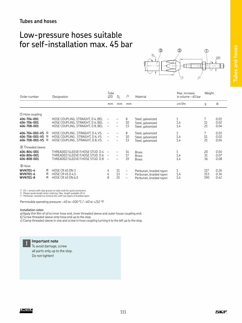
Tubes
and h
ose
s
Order number DesignationTube ∅D D1 Material
Max increase in volume ∼ 40 bar
Weight
mm mm mm cm3/m g lb
Hose coupling
406-704-001 HOSE COUPLING, STRAIGHT, D 4, BEL – – 8 Steel, galvanized 1 7 0.01406-706-001 HOSE COUPLING, STRAIGHT, D 6, BEL – – 10 Steel, galvanized 1,4 11 0.02406-708-001 HOSE COUPLING, STRAIGHT, D 8, BEL – – 13 Steel, galvanized 1,4 21 0.04
406-704-001-VS 1) HOSE COUPLING , STRAIGHT, D 4, VS – – 8 Steel, galvanized 1 7 0.01406-706-001-VS 1) HOSE COUPLING , STRAIGHT, D 6, VS – – 10 Steel, galvanized 1,4 11 0.02406-708-001-VS 1) HOSE COUPLING , STRAIGHT, D 8, VS – – 13 Steel, galvanized 1,4 21 0.04
Threaded sleeve
406-804-001 THREADED SLEEVE F HOSE STUD D 4 – – 14 Brass 1 20 0.04406-806-001 THREADED SLEEVE F HOSE STUD D 6 – – 17 Brass 1,4 31 0.07406-808-001 THREADED SLEEVE F HOSE STUD D 8 – – 19 Brass 1,4 36 0.08
Hose
WVN701-4 2) HOSE CR 45 DN 3 4 11 – Perbunan, braided rayon 1 117 0.26WVN701-6 2) HOSE CR 45 D 4,5 6 13 – Perbunan, braided rayon 1,4 153 0.34WVN701-8 2) HOSE CR 45 DN 6,5 8 15 – Perbunan, braided rayon 1,4 190 0.42
1) VS = version with claw groove on tube ends for quick connectors2) Please quote length when ordering Max length available 20 m3) Perbunan, resistant to mineral oils, with two layers of braided rayon
Permissible operating pressure: –40 to +100 °C / –40 to +212 °F
Installation notesa) Apply thin film of oil to inner hose end, inner threaded sleeve and outer house coupling end b) Screw threaded sleeve onto hose end up to the stop c) Clamp threaded sleeve in vise and screw in hose coupling turning it to the left up to the stop
Tubes and hoses
Low-pressure hoses suitable for self-installation max. 45 bar
∅DD1
Important noteTo avoid damage, screw
all parts only up to the stop
Do not tighten!
!
111

Tubes
and h
ose
s
Tubes and hoses
High-pressure hoses with pipe stud for high volume
Order number DesignationNominal diameter ND
L Material hose FittingOperating pressure max
Weight
mm mm bar psi g lb
225-12486-5 HOSE HY200 NW 6X840, STU10 6 840 Perbunan, braided steel 1) Pipe stud 10 200 2 900 0,36 0.79225-12324-3 HOSE HY560 NW 8X540, STU10 8 540 Perbunan, braided steel 1) Pipe stud 10 560 8 120 0,31 0.68225-12324-5 HOSE HY560 NW 8X740, STU10 8 740 Perbunan, braided steel 1) Pipe stud 10 560 8 120 0,37 0.82225-12324-8 HOSE HY560 NW 8X1040, STU10 8 1 040 Perbunan, braided steel 1) Pipe stud 10 560 8 120 0,44 0.97225-12325-1 HOSE HY560 NW 8X1540, STU10 8 1 540 Perbunan, braided steel 1) Pipe stud 10 560 8 120 0,7 1.54225-12325-2 HOSE HY560 NW 8X2040, STU10 8 2 040 Perbunan, braided steel 1) Pipe stud 10 560 8 120 0,91 2.01225-12576-1 HOSE ND 16 NW13X840, STU15 13 840 Perbunan, braided steel 1) Pipe stud 15 16 230 0,55 1.21225-13039-2 HOSE ND 16 NW13X1040, STU15 13 1 040 Perbunan, braided steel 1) Pipe stud 15 16 230 0,6 1.32225-13039-8 HOSE ND 16 NW13X1240, STU15 13 1 240 Perbunan, braided steel 1) Pipe stud 15 16 230 0,95 2.09225-12576-3 HOSE ND 16 NW13X1540, STU15 13 1 540 Perbunan, braided steel 1) Pipe stud 15 16 230 0,86 1.9225-12576-2 HOSE ND 16 NW13X2040, STU15 13 2 040 Perbunan, braided steel 1) Pipe stud 15 16 230 1,03 2.27225-12414-6 HOSE HY400 DN16X1200 DKOS /DKOS 16 1 200 Perbunan, braided steel 1) DKOS/DKOS 400 5 800 1,8 3.97225-12414-7 HOSE HY400 DN16X1500 DKOS /DKOS 16 1 500 Perbunan, braided steel 1) DKOS/DKOS 400 5 800 2,2 4.85225-12414-8 HOSE HY400 DN16X2000 DKOS /DKOS 16 2 000 Perbunan, braided steel 1) DKOS/DKOS 400 5 800 3 6.62
1) Perbunan, resistant to mineral oils, with two layers of braided steel
L
ND
Hose Pipe studPipe stud
112

Tubes
and h
ose
s
Order number Designation L Material hoseOperating pressure max
Weight
mm bar psi g lb
666-34221-9 HDS 1 HOSE NW 4X 200 200 Perbunan, braided steel 1) 350 5 080 41 0.09666-34220-1 HDS 1 HOSE NW 4X 300 300 Perbunan, braided steel 1) 350 5 080 60 0.13666-36087-2 HDS 1 HOSE NW 4X 400 400 Perbunan, braided steel 1) 350 5 080 70 0.15666-85311-1 HDS 1 HOSE NW 4X 510 510 Perbunan, braided steel 1) 350 5 080 79 0.17666-34639-5 HDS 1 HOSE NW 4X 600 600 Perbunan, braided steel 1) 350 5 080 80 0.18666-36059-8 HDS 1 HOSE NW 4X 700 700 Perbunan, braided steel 1) 350 5 080 86 0.19666-36087-1 HDS 1 HOSE NW 4X 800 800 Perbunan, braided steel 1) 350 5 080 93 0.21666-36831-9 HDS 1 HOSE NW 4X 900 900 Perbunan, braided steel 1) 350 5 080 96 0.21666-36087-3 HDS 1 HOSE NW 4X 1000 1 000 Perbunan, braided steel 1) 350 5 080 101 0.22666-34221-5 HDS 1 HOSE NW 4X 1250 1 250 Perbunan, braided steel 1) 350 5 080 122 0.27666-36081-7 HDS 1 HOSE NW 4X 1500 1 500 Perbunan, braided steel 1) 350 5 080 136 0.30666-34578-9 HDS 1 HOSE NW 4X 1750 1 750 Perbunan, braided steel 1) 350 5 080 140 0.31666-36087-7 HDS 1 HOSE NW 4X 2000 2 000 Perbunan, braided steel 1) 350 5 080 146 0.32666-36081-8 HDS 1 HOSE NW 4X 2500 2 500 Perbunan, braided steel 1) 350 5 080 181 0.40666-36081-9 HDS 1 HOSE NW 4X 3000 3 000 Perbunan, braided steel 1) 350 5 080 207 0.46666-34028-2 HDS 1 HOSE NW 4X 3500 3 500 Perbunan, braided steel 1) 350 5 080 230 0.51666-36087-8 HDS 1 HOSE NW 4X 4000 4 000 Perbunan, braided steel 1) 350 5 080 260 0.57666-34028-3 HDS 1 HOSE NW 4X 4500 4 500 Perbunan, braided steel 1) 350 5 080 286 0.63666-34578-5 HDS 1 HOSE NW 4X 5000 5 000 Perbunan, braided steel 1) 350 5 080 301 0.66
1) Perbunan, resistant to mineral oils, with two layers of braided steel
Tubes and hoses
High-pressure hoses ∅ 8.6 mm (ND4) pipe stud 6 mm
L
4 66
Hose Pipe studPipe stud
113

Tubes
and h
ose
s
∅D
L
∅ND
Tubes and hoses
High-pressure hoses for self-installation
Order number 1) Designation Tube ∅D
Nominal diameter ND
Length Material hoseBurst pressure
Weight
mm mm m bar psi g lb
111-35114-1 HOSE PL300 NW4,0 HIGHFLEXIBLE 8,6 4 1 Polyamide, polyurethane 2) 840 12 183 48 0.1061110-00000002 HP HOSE 8,6/4,1-PA6/PUR-BK COIL50M 8,6 4 50 Polyamide, polyurethane 2) 840 12 183 2400 5.291111-35301-4 HOSE, PL400 NW6,0 HIGHFLEXIBLE 11,2 6 1 Polyamide, polyurethane 2) 840 12 183 70 0.1541110-00000001 HP HOSE 11,3/6,4-PA6/PUR-BK COIL50M 11,2 6 50 Polyamide, polyurethane 2) 840 12 183 3500 7.716WVN711-10 HOSE, 3TE,NW8,0 HIGHFLEXIBLE 16,5 8 1 Polyamide, polyurethane 2) 840 12 183 198 0.432
1) Hoses can be delivered prefilled wiht lurbicant on request 2) Inner hose = polyamide,soft; pressure reinforcement = polyamide high strength; sheathing = polyurethane
Scheme - High-pressure hose self-mounting components
Hose Threaded sleeve Hose couplingThreaded sleeveHose coupling
Installation notesa) Apply thin film of oil to inner hose end, inner threaded sleeve and outer house coupling end b) Screw threaded sleeve onto hose end up to the stop c) Clamp threaded sleeve in vise and screw in hose coupling turning it to the left up to the stop
Important noteTo avoid damage, screw
all parts only up to the stop
Do not tighten!
!
114
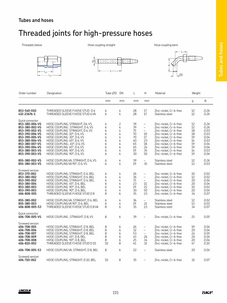
Tubes
and h
ose
s
Tubes and hoses
Threaded joints for high-pressure hoses
L1
L2
Order number Designation Tube ∅D DN L H Material Weight
mm mm mm mm g lb
853-540-010 THREADED SLEEVE F HOSE STUD D 6 6 4 28 17 Zinc-nickel, Cr-6-free 12 0.26432-23676-1 THREADED SLEEVE F HOSE STUD 6 VA 6 4 28 17 Stainless steel 12 0.26
Quick connector853-380-006-VS HOSE COUPLING, STRAIGHT, D4, VS 4 2 39 – Zinc-nickel, Cr-6-free 12 0.26853-380-002-VS HOSE COUPLING , STRAIGHT, D 6, VS 6 4 39 – Zinc-nickel, Cr-6-free 12 0.26853-390-002-VS HOSE COUPLING STRAIGHT, D 6, VS 6 4 75 – Zinc-nickel, Cr-6-free 18 0.03853-390-006-VS HOSE COUPLING 10°, D 6, VS 6 4 70 10 Zinc-nickel, Cr-6-free 18 0.03853-390-005-VS HOSE COUPLING 30°, D 6, VS 6 4 70 17 Zinc-nickel, Cr-6-free 19 0.04853-380-004-VS HOSE COUPLING 45°, D 6, VS 6 4 40 23 Zinc-nickel, Cr-6-free 14 0.03853-380-007-VS HOSE COUPLING , 45°, D 6, VS 6 4 65 18 Zinc-nickel, Cr-6-free 19 0.04853-390-004-VS HOSE COUPLING 45°, D 6, VS 6 4 65 24 Zinc-nickel, Cr-6-free 19 0.04853-380-003-VS HOSE COUPLING 90°, D 6, VS 6 4 19 35 Zinc-nickel, Cr-6-free 14 0.03853-390-003-VS HOSE COUPLING 90°, D 6, VS 6 4 30 50 Zinc-nickel, Cr-6-free 19 0.04
855-380-002-VS HOSE COUPLING VA, STRAIGHT, D 6, VS 6 4 39 – Stainless steel 12 0.26855-380-003-VS HOSE COUPLING VA 90°, D 6, VS 6 4 19 35 Stainless steel 13 0.03
Screwed version853-370-002 HOSE COUPLING, STRAIGHT, D 6, BEL 6 4 26 – Zinc-nickel, Cr-6-free 10 0.02853-380-002 HOSE COUPLING, STRAIGHT, D 6, BEL 6 4 36 – Zinc-nickel, Cr-6-free 12 0.02853-390-002 HOSE COUPLING, STRAIGHT, D 6, BEL 6 4 75 – Zinc-nickel, Cr-6-free 20 0.04853-380-004 HOSE COUPLING 45°, D 6, BEL 6 4 23 11 Zinc-nickel, Cr-6-free 20 0.04853-380-003 HOSE COUPLING 90°, D 6, BEL 6 4 19 21 Zinc-nickel, Cr-6-free 10 0.02853-390-003 HOSE COUPLING 90°, D 6, BEL 6 4 30 50 Zinc-nickel, Cr-6-free 20 0.04406-808-005 THREADED SLEEVE F HOSE STUD D 8 8 6 35 23 Zinc-nickel, Cr-6-free 34 0.07
855-380-002 HOSE COUPLING VA, STRAIGHT, D 6, BEL 6 4 36 – Stainless steel 12 0.02855-380-003 HOSE COUPLING VA 90°, D 6, BEL 6 4 19 21 Stainless steel 13 0.02406-808-005-S3 THREADED SLEEVE F HOSE STUD D 8 VA 8 6 35 23 Stainless steel 34 0.07
Quick connector406-708-005-VS HOSE COUPLING , STRAIGHT, D 8, VS 8 6 39 – Zinc-nickel, Cr-6-free 21 0.05
Screwed version406-708-005 HOSE COUPLING, STRAIGHT, D 8, BEL 8 6 26 – Zinc-nickel, Cr-6-free 19 0.04406-708-006 HOSE COUPLING, STRAIGHT, D 8, BEL 8 6 32 – Zinc-nickel, Cr-6-free 20 0.04406-708-007 HOSE COUPLING, STRAIGHT, D 8, BEL 8 6 53 – Zinc-nickel, Cr-6-free 24 0.05406-708-009 HOSE COUPLING 45°, D 8, BEL 8 6 43 26 Zinc-nickel, Cr-6-free 20 0.04406-708-008 HOSE COUPLING 90°, D 8, BEL 8 6 25 34 Zinc-nickel, Cr-6-free 20 0.04406-810-002 THREADED SLEEVE F HOSE STUD D 10 10 8 41 32 Zinc-nickel, Cr-6-free 47 0.10
406-708-005-S3 HOSE COUPLING VA, STRAIGHT, D 8, BEL 8 6 22 – Stainless steel 20 0.04
Screwed version406-710-002 HOSE COUPLING, STRAIGHT, D 10, BEL 10 8 35 – Zinc-nickel, Cr-6-free 32 0.07
L
H
∅D
L
∅D
Hose coupling straightThreaded sleeve Hose coupling bent
115

Fixing material
Fix
ing m
ate
rial
Description
The following chapter includes the screws and bolts for fixing the
individual components of lubrication systems, as well as cable straps,
mounting bases and a large selection of pipe clamps for fixing the
pipes
Clamps for pipes with a diameter of 8 mm and 10 mm are available
in two versions: One according to DIN 72573 and another reinforced
design version with a thicker and wider metal sheet than DIN 72573
For use in corrosive areas, various mounting parts are also available
in stainless steel (material 1 4571)
Features and benefits
• Wide product range with many different dimensions
• Recommended and reliable fixing material for lubrication system components such as pipes and tubes
• Suitable for all types of automatic lubrication systems
Applications
• Metal forming machines
• On- and off-road vehicles
• Construction and mining
• Agriculture machinery
• Packaging machines
• General industry
• Etc
116

Fix
ing m
ate
rial
Fixing material
Fixing clips
L2
S
D1
L1
B
D
Order number DesignationTube ∅D for tube B D1 L1 L2 S Material
Weight (100 pcs)
mm mm mm mm mm mm mm g lb
602-002 TUBE CLAMP ST-Z D 2 5 (2X) 2,5 2 10 3,5 13,8 5 1,5 Mild steel 200 0.44604-002 TUBE CLAMP ST-Z D 4 (2X) 4 2 10 5,5 22,6 9 1,5 Mild steel 200 0.44604-003 TUBE CLAMP ST-Z D 4 (3X) 4 3 10 5,5 26,6 9 1,5 Mild steel 300 0.66
L2
S
D1
L1
B
D
Order number DesignationTube ∅D B D1 L1 L2 S Material
Weight (100 pcs)
mm mm mm mm mm g lb
Steel602-001 TUBE CLAMP ST-Z D 2 5 (1X) 2,5 mm 10 3,5 11,25 5 1,5 Steel 200 0.44604-001 TUBE CLAMP ST-Z D 4 (1X) 4 mm 10 5,5 18,5 9 1,5 Steel 200 0.44606-010 TUBE CLAMP ST-Z D 6 (1X) 6 mm 10 5,5 20,5 10 1,5 Steel 300 0.66608-001 TUBE CLAMP ST-Z D 8 (1X) 8 mm 10 5,5 23,5 12 1,5 Steel 300 0.66610-001 TUBE CLAMP ST-Z D10 (1X) 10 mm or 1/8 10 5,5 25,5 13 1,5 Steel 400 0.88612-001 TUBE CLAMP ST-Z D12 (1X) 12 mm 20 6,8 35 18 2 Steel 500 1.1608-003 TUBE CLAMP ST-Z D8 (1X) D4 (2X) 8/4 10 5,5 34 12 1,5 Steel 100 0.22
Zinc-plated steel226-12337-1 TUBE CLAMP ST-Z D 8(1X)ZG 8 mm 15 7 28 15,5 2 Zinc-plated steel 700 1.54226-12338-1 TUBE CLAMP ST-Z D10(1X)ZG 10 mm 15 7 30 15 2 Zinc-plated steel 800 1.76
Stainless steel226-12335-7 TUBE CLAMP 1 4571 D 6 (1X) 6 mm 10 4,8 20,5 10 1 Stainless steel 200 0.44226-13717-1 TUBE CLAMP 1 4571 D 8(1X)ZG 8 mm 15 7 28 15,5 2 Stainless steel 700 1.54226-13673-1 TUBE CLAMP 1 4571 D10(1X)ZG 10 mm 15 7 30 15 2 Stainless steel 800 1.76
602-001 – 612-001, 226-xxxxx-1
L1
D1
B
L2 9 4
D
D
608-003
117
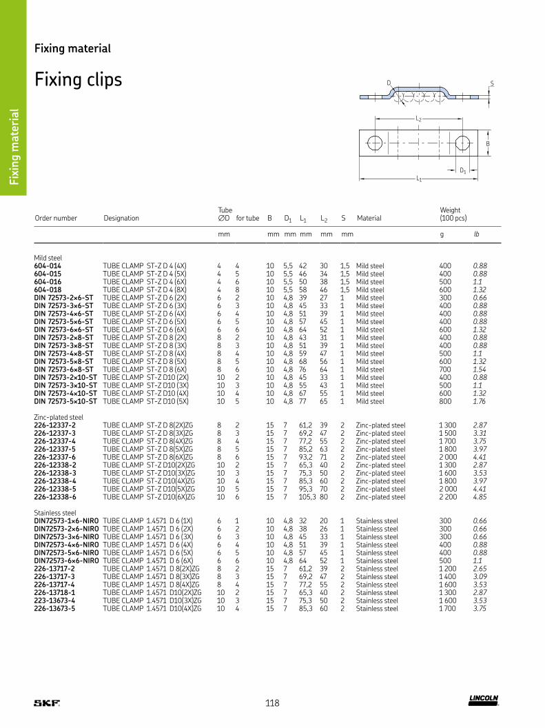
Fix
ing m
ate
rial
Fixing material
Fixing clips S
L2
L1
D1
B
D
Order number DesignationTube ∅D for tube B D1 L1 L2 S Material
Weight (100 pcs)
mm mm mm mm mm mm g lb
Mild steel604-014 TUBE CLAMP ST-Z D 4 (4X) 4 4 10 5,5 42 30 1,5 Mild steel 400 0.88604-015 TUBE CLAMP ST-Z D 4 (5X) 4 5 10 5,5 46 34 1,5 Mild steel 400 0.88604-016 TUBE CLAMP ST-Z D 4 (6X) 4 6 10 5,5 50 38 1,5 Mild steel 500 1.1604-018 TUBE CLAMP ST-Z D 4 (8X) 4 8 10 5,5 58 46 1,5 Mild steel 600 1.32DIN 72573-2×6-ST TUBE CLAMP ST-Z D 6 (2X) 6 2 10 4,8 39 27 1 Mild steel 300 0.66DIN 72573-3×6-ST TUBE CLAMP ST-Z D 6 (3X) 6 3 10 4,8 45 33 1 Mild steel 400 0.88DIN 72573-4×6-ST TUBE CLAMP ST-Z D 6 (4X) 6 4 10 4,8 51 39 1 Mild steel 400 0.88DIN 72573-5×6-ST TUBE CLAMP ST-Z D 6 (5X) 6 5 10 4,8 57 45 1 Mild steel 400 0.88DIN 72573-6×6-ST TUBE CLAMP ST-Z D 6 (6X) 6 6 10 4,8 64 52 1 Mild steel 600 1.32DIN 72573-2×8-ST TUBE CLAMP ST-Z D 8 (2X) 8 2 10 4,8 43 31 1 Mild steel 400 0.88DIN 72573-3×8-ST TUBE CLAMP ST-Z D 8 (3X) 8 3 10 4,8 51 39 1 Mild steel 400 0.88DIN 72573-4×8-ST TUBE CLAMP ST-Z D 8 (4X) 8 4 10 4,8 59 47 1 Mild steel 500 1.1DIN 72573-5×8-ST TUBE CLAMP ST-Z D 8 (5X) 8 5 10 4,8 68 56 1 Mild steel 600 1.32DIN 72573-6×8-ST TUBE CLAMP ST-Z D 8 (6X) 8 6 10 4,8 76 64 1 Mild steel 700 1.54DIN 72573-2×10-ST TUBE CLAMP ST-Z D10 (2X) 10 2 10 4,8 45 33 1 Mild steel 400 0.88DIN 72573-3×10-ST TUBE CLAMP ST-Z D10 (3X) 10 3 10 4,8 55 43 1 Mild steel 500 1.1DIN 72573-4×10-ST TUBE CLAMP ST-Z D10 (4X) 10 4 10 4,8 67 55 1 Mild steel 600 1.32DIN 72573-5×10-ST TUBE CLAMP ST-Z D10 (5X) 10 5 10 4,8 77 65 1 Mild steel 800 1.76
Zinc-plated steel226-12337-2 TUBE CLAMP ST-Z D 8(2X)ZG 8 2 15 7 61,2 39 2 Zinc-plated steel 1 300 2.87226-12337-3 TUBE CLAMP ST-Z D 8(3X)ZG 8 3 15 7 69,2 47 2 Zinc-plated steel 1 500 3.31226-12337-4 TUBE CLAMP ST-Z D 8(4X)ZG 8 4 15 7 77,2 55 2 Zinc-plated steel 1 700 3.75226-12337-5 TUBE CLAMP ST-Z D 8(5X)ZG 8 5 15 7 85,2 63 2 Zinc-plated steel 1 800 3.97226-12337-6 TUBE CLAMP ST-Z D 8(6X)ZG 8 6 15 7 93,2 71 2 Zinc-plated steel 2 000 4.41226-12338-2 TUBE CLAMP ST-Z D10(2X)ZG 10 2 15 7 65,3 40 2 Zinc-plated steel 1 300 2.87226-12338-3 TUBE CLAMP ST-Z D10(3X)ZG 10 3 15 7 75,3 50 2 Zinc-plated steel 1 600 3.53226-12338-4 TUBE CLAMP ST-Z D10(4X)ZG 10 4 15 7 85,3 60 2 Zinc-plated steel 1 800 3.97226-12338-5 TUBE CLAMP ST-Z D10(5X)ZG 10 5 15 7 95,3 70 2 Zinc-plated steel 2 000 4.41226-12338-6 TUBE CLAMP ST-Z D10(6X)ZG 10 6 15 7 105,3 80 2 Zinc-plated steel 2 200 4.85
Stainless steelDIN72573-1×6-NIRO TUBE CLAMP 1 4571 D 6 (1X) 6 1 10 4,8 32 20 1 Stainless steel 300 0.66DIN72573-2×6-NIRO TUBE CLAMP 1 4571 D 6 (2X) 6 2 10 4,8 38 26 1 Stainless steel 300 0.66DIN72573-3×6-NIRO TUBE CLAMP 1 4571 D 6 (3X) 6 3 10 4,8 45 33 1 Stainless steel 300 0.66DIN72573-4×6-NIRO TUBE CLAMP 1 4571 D 6 (4X) 6 4 10 4,8 51 39 1 Stainless steel 400 0.88DIN72573-5×6-NIRO TUBE CLAMP 1 4571 D 6 (5X) 6 5 10 4,8 57 45 1 Stainless steel 400 0.88DIN72573-6×6-NIRO TUBE CLAMP 1 4571 D 6 (6X) 6 6 10 4,8 64 52 1 Stainless steel 500 1.1226-13717-2 TUBE CLAMP 1 4571 D 8(2X)ZG 8 2 15 7 61,2 39 2 Stainless steel 1 200 2.65226-13717-3 TUBE CLAMP 1 4571 D 8(3X)ZG 8 3 15 7 69,2 47 2 Stainless steel 1 400 3.09226-13717-4 TUBE CLAMP 1 4571 D 8(4X)ZG 8 4 15 7 77,2 55 2 Stainless steel 1 600 3.53226-13718-1 TUBE CLAMP 1 4571 D10(2X)ZG 10 2 15 7 65,3 40 2 Stainless steel 1 300 2.87223-13673-4 TUBE CLAMP 1 4571 D10(3X)ZG 10 3 15 7 75,3 50 2 Stainless steel 1 600 3.53226-13673-5 TUBE CLAMP 1 4571 D10(4X)ZG 10 4 15 7 85,3 60 2 Stainless steel 1 700 3.75
118

Fix
ing m
ate
rial
Fixing material
Fixing clips
L1
D1
L2
S
B C
D
Order number DesignationTube ∅D B C D1 L1 L2 S Material
Weight (100 pcs)
mm in mm mm mm mm mm mm g lb
604-004 TUBE CLAMP ST-Z D12 (1X) 12 – 24 14 5,5 27 13 1,5 Steel 500 1.1606-014 TUBE CLAMP ST-Z D14 (1X) 14 1/4 30 15 6,3 32,5 16 2 Steel 1 200 2.65608-004 TUBE CLAMP ST-Z D18 (1X) 18 3/8 36 20 7 40 21 2 Steel 1 200 2.65610-004 TUBE CLAMP ST-Z D20 (1X) 20 1/2 36 20 7 40 21 2 Steel 1 200 2.65
H
S
∅D3B2 B1
∅D2
∅D1
Order number Designation ∅D1 ∅D2 ∅D3 B1 B2 H S MaterialWeight (100 pcs)
mm mm mm mm mm mm mm g lb
941-206-104 TUBE CLAMP ST-RUB D 6 F FAST SCREW M5 6 11,8 5,2 12 15 11 0,5 Steel, galvanized 400 0.88941-206-108 TUBE CLAMP ST-RUB D 6 F FAST SCREW M6 6 11,8 6,4 15 18,5 4,2 0,6 Steel, galvanized 700 1.54941-208-104 TUBE CLAMP ST-RUB D 8 F FAST SCREW M6 8 15,4 6,4 15 18,5 15,2 0,6 Steel, galvanized 800 1.76941-209-104 TUBE CLAMP ST-RUB D 9 F FAST SCREW M5 9 5 5,2 12 5 12,5 0,5 Steel, galvanized 500 1.1941-209-105 TUBE CLAMP ST-RUB D 9 F FAST SCREW M6 9 15 6,4 15 18,5 15,7 0,6 Steel, galvanized 900 1.98941-210-104 TUBE CLAMP ST-RUB D10 F FAST SCREW M6 10 17,4 6,4 15 18,5 16,2 0,6 Steel, galvanized 900 1.98941-212-104 TUBE CLAMP ST-RUB D12 F FAST SCREW M6 12 19,4 6,4 15 18,5 17,2 0,6 Steel, galvanized 1 000 2.21941-213-104 TUBE CLAMP ST-RUB D13 F FAST SCREW M6 13 20,4 6,4 15 18,5 7,7 0,6 Steel, galvanized 1 100 2.43941-215-104 TUBE CLAMP ST-RUB D15 F FAST SCREW M6 15 22,4 6,4 5 18,5 18,7 0,8 Steel, galvanized 2 000 4.41941-217-104 TUBE CLAMP ST-RUB D17 F FAST SCREW M5 17 23 5,2 12 15 16,5 0,5 Steel, galvanized 800 1.76941-217-105 TUBE CLAMP ST-RUB D17 F FAST SCREW M6 17 23 6,4 15 8,5 19,7 0,8 Steel, galvanized 1 500 3.31941-218-101 TUBE CLAMP ST-RUB D18 F FAST SCREW M6 18 24 6,4 15 8,5 20,2 0,6 Steel, galvanized 1 400 3.09941-220-104 TUBE CLAMP ST-RUB D20 F FAST SCREW M6 20 27,6 6,4 15 8,5 21,2 0,8 Steel, galvanized 1 500 3.31941-222-100 TUBE CLAMP ST-RUB D22 F FAST SCREW M6 22 28 6,4 15 18,5 22,2 0,8 Steel, galvanized 1 700 3.75941-225-104 TUBE CLAMP ST-RUB D25 F FAST SCREW M6 25 31 6,4 15 18,5 23,7 0,8 Steel, galvanized 2 000 4.41
119

Fix
ing m
ate
rial
L
B
99
2.5
Cable straps898-610-000, 898-710-000, 898-710-001 898-510-000
Order number Designation L B Material Weight (100 pcs)
mm mm g lb
898-610-000 CABLE STRAP SW 204LGX4 7 197 4,9 Polyamide 100 0.22898-710-000 CABLE STRAP SW 302LGX4 8 302 4,9 Polyamide 200 0.44898-710-001 CABLE STRAP SW 360LGX7 5 360 7,5 Polyamide 500 1.10
For automatic pincers898-510-000 CABLE STRAP SW 100LGX2 5 99 2,5 Polyamide 100 0.22
Order number Designation Tube ∅ Material Weight
mm g lb
941-606-000 TUBE CLAMP 106 PP 6 Polypropylene 10 0.02941-608-000 TUBE CLAMP 108 PP 8 Polypropylene 10 0.02941-610-000 TUBE CLAMP 110 PP 10 Polypropylene 5 0.01
Tube clamp PP with weld plate, standard series226-12343-5 TUBE CLAMP SP 110 PP -LI 10 Polypropylene 40 0.09226-12343-1 TUBE CLAMP SP 320 PP -LI 20 Polypropylene 77 0.17226-13097-3 TUBE CLAMP SP 320 /20 PP -GD -AS 2 x 20 Polypropylene 173 0.38226-12343-2 TUBE CLAMP SP 430 PP -LI 30 Polypropylene 80 0.18
Tube clamp PP with weld plate and cover plate, heavy series226-13058-3 TUBE CLAMP SPAL4020 PP -DPAL-AS 20 Polypropylene 394 0.87226-13058-5 TUBE CLAMP SPAL5030 PP -DPAL-AS 30 Polypropylene 480 1.06
28
30 27
Tube ∅
Fixing material
Pipe brackets acc. to DIN 3015
120

Fix
ing m
ate
rial
Fixing bolts
DIN7513
L D2
D1
Order number Designation D1 L D2 B Material Weight
mm mm mm mm mm g lb
201-12015-5 SCREW,SOCK,HEX 8 8 M4X 20CF M4 20 7 14 3 Steel, galvanized 3 0.007201-12019-9 SCREW,SOCK,HEX 8 8 M6X 16CF M6 16 10 18 5 Steel, galvanized 6 0.013201-12018-7 SCREW,SOCK,HEX 8 8 M6X 25CF M6 25 10 18 5 Steel, galvanized 7 0.015201-12019-6 SCREW,SOCK,HEX 8 8 M6X 60CF M6 60 10 18 5 Steel, galvanized 14 0.031201-12021-3 SCREW,SOCK,HEX 8 8 M8X 16CF M8 16 13 12 6 Steel, galvanized 20 0.044DIN931-M6×30-8 8 SCREW,HEX 8 8 M 6X 30CF M6 30 10 18 10 Steel, galvanized 8 0.018DIN933-M4×10-8 8 SCREW,HEX 8 8 M 4X 10CF M4 10 7 5 – Steel, galvanized 2 0.004200-13092-1 SCREW,HEX 8 8 M 5X 12CF M5 12 8 6 – Steel, galvanized 3 0.007200-13017-9 SCREW,HEX 8 8 M 5X 16CF M5 16 8 11 Steel, galvanized 3 0.007200-13017-5 SCREW,HEX 8 8 M 5X 45CF M5 45 8 40 Steel, galvanized 7 0.015200-13022-4 SCREW,HEX 8 8 M 6X 16CF M6 16 10 9 – Steel, galvanized 5 0.011200-13022-7 SCREW,HEX 8 8 M 6X 20CF M6 20 10 13 – Steel, galvanized 6 0.013200-13022-1 SCREW,HEX 8 8 M 6X 25CF M6 25 10 19 – Steel, galvanized 7 0.015200-13037-3 SCREW,HEX 8 8 M 6X 60CF M6 60 10 53 Steel, galvanized 14 0.031200-12553-4 SCREW,HEX 8 8 M 8X 20CF M8 20 13 11 – Steel, galvanized 12 0.026200-10406-7 SCREW,HEX 8 8 M 8X 25CF M8 25 13 16 – Steel, galvanized 13 0.029200-12007-6 SCREW,HEX 8 8 M 8X 30CF M8 30 13 21 Steel, galvanized 15 0.033200-12553-8 SCREW,HEX 8 8 M 8X 40CF M8 40 13 31 Steel, galvanized 18 0.04200-12399-2 SCREW,HEX 8 8 M 8X80CF M8 80 13 71 Steel, galvanized 34 0.075200-12523-3 SCREW,HEX 8 8 M10X 40CF M10 40 16 39 – Steel, galvanized 30 0.066200-12009-7 SCREW,HEX 8 8 M12X 40CF M12 40 18 28 Steel, galvanized 34 0.075
DIN7513-BM4×20 SELF-TAPPING SCREW M4 20 7 – Steel, galvanized 2 0.004DIN7513-BM4×25 SELF-TAPPING SCREW M4 25 7 – Steel, galvanized 2 0.004206-12124-3 SCREW,SELF-TAPP C15 BM 5 0X 10 M5 10 8,5 – Steel, galvanized 2 0.004206-12125-4 SCREW,SELF-TAPP C15 BM 6 0X 16Z M6 16 10 – Steel, galvanized 5 0.011DIN7513-BM6×25 SELF-TAPPING SCREW M6 25 10 – Steel, galvanized 6 0.013
DIN912-M3×8-A4 SCREW,SOCK,HEX A4 M 3X 8 M3 8 5,5 – Stainless steel 1 0.002DIN912-M4×12-A4 SCREW,SOCK,HEX A4 M 4X12 M4 12 7 – Stainless steel 2 0.004DIN912-M5×10-A2 SCREW,SOCK,HEX A4 M 5X10 M5 10 7 – Stainless steel 2 0.004
Fixing material
Mounting base
Order number Designation MaterialWeight (100 pcs)
g lb
179-990-186 MOUNTING PLATE 25,4X25,4 ABS 100 0.22
5
3.7
25.4
4.2
25.417.8
DIN912
DIN931 / DIN933
BL D2
D1
DIN931 / DIN933
DIN7513
L D2B
D1
Self-stick foil
121

Description
Couplings for hydraulic or lubrication systems are required
whenever a virtually leakage-free flow of media is to be separated
or distributed Typically, this happens e g when a pump is used to fill
several lubricant reservoirs and must be connected and discon-
nected again and again
For each coupling design/model, a corresponding hose is required
Conveniently, the coupling side is on the hose of the filling pump and
the counterpart, the coupling nipple, is attached to the reservoir
Another coupling application in the field of lubrication systems is the
coupling and uncoupling of groups of machines that need not be
continuously supplied by one lubrication pump, e g for vehicle lubri-
cation and trailer lubrication
When selecting a coupling, the maximum possible pump/system
pressure must be considered In addition, there are couplings suita-
ble mainly for either indoor or outdoor applications If the application
is not accurately defined before ordering, stainless steel or sur-
face-treated couplings are the best choice Couplings protect hydrau-
lic fluids or lubricants for contamination and allow quick and
high-pressure media flows
Features and benefits
• Wide product range with different pressure rates and sizes
• Available for filling as well as for operation of automatic lubrication systems
• Quick couplings (ESK) for under-pressure coupling available
• Virtually leakage-free filling
Applications
• All kinds of lubrication systems
• Printing and packaging machines
• Construction and mining
• Metal forming machines
• Vehicles, trucks, loaders
• Agriculture machinery
• General industry
• Machine tools
• Etc
Cuti
ing s
leev
e fitt
ings
Couplings
Couplings
122

Couplings
Couplings
Low-pressure quick-disconnect couplingsL2
L1 33
Order number Designation Tube ∅ D1 1) L1 L2 Material
Operating pressure max Weight
mm mm mm mm bar psi g lb
207-168-2 COUPLING, COMPLETE 6 M10×1 – 65 Steel, galvanized 45 653 150 0.33207-188-2 COUPLING, COMPLETE 8 M14×1,5 – 71,5 Steel, galvanized 45 653 152 0.34
207-168 U7 OUTER COUPLING MEMBER 6 – 51,5 – Steel, galvanized 45 653 120 0.26207-188 U11 OUTER COUPLING MEMBER 8 – 58 – Steel, galvanized 45 653 130 0.29
207-168 U2 INNER COUPLING MEMBER – – – – Steel, galvanized 45 653 22 0.05
Both coupling members are shut off when disconnected!
1) Ports tapped for solderless tube connection
D1
9
L2
L1
M14×1.5
22 17
Coupling, complete Outer coupling member Inner coupling member
L
D1
G1/4
L
G1/4
Medium- and high-pressure quick-disconnect couplings
Order number Designation Tube ∅ D1 L MaterialOperating pressure max Weight
mm mm mm mm bar psi g lb
995-001-525 PLUG AND SOCKET COUPLING, TUBE 4 4 10 68 10 Steel, galvanized 100 1 450 30 0.07995-001-526 PLUG AND SOCKET COUPLING, TUBE 6 6 15 80 12 Steel, galvanized 100 1 450 35 0.08
626-26246-1 COUPLING ESK R1/4I D – – 124 27 Steel, galvanized 300 4 351 760 1.68
995-001-525, 995-001-526 626-26246-1
123
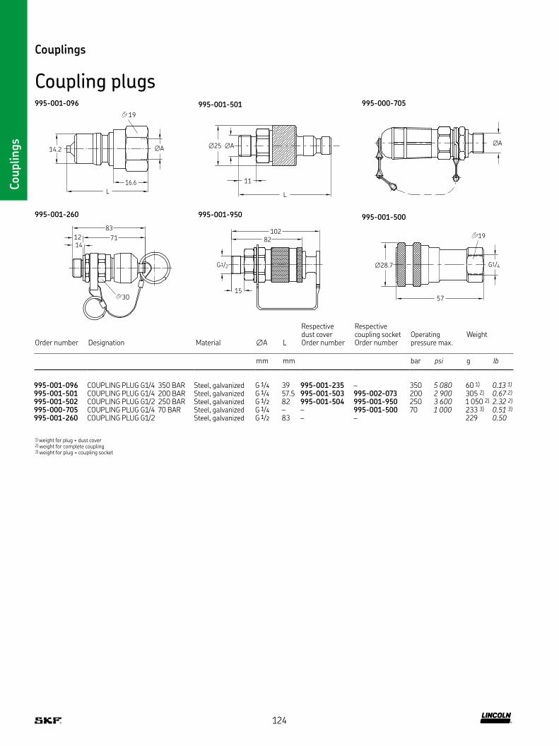
Couplings
Couplings
Coupling plugs
Order number Designation Material ∅A L
Respectivedust coverOrder number
Respectivecoupling socketOrder number
Operating pressure max
Weight
mm mm bar psi g lb
995-001-096 COUPLING PLUG G1/4 350 BAR Steel, galvanized G 1/4 39 995-001-235 – 350 5 080 60 1) 0.13 1)
995-001-501 COUPLING PLUG G1/4 200 BAR Steel, galvanized G 1/4 57 5 995-001-503 995-002-073 200 2 900 305 2) 0.67 2)
995-001-502 COUPLING PLUG G1/2 250 BAR Steel, galvanized G 1/2 82 995-001-504 995-001-950 250 3 600 1 050 2) 2.32 2)
995-000-705 COUPLING PLUG G1/4 70 BAR Steel, galvanized G 1/4 – – 995-001-500 70 1 000 233 3) 0.51 3)
995-001-260 COUPLING PLUG G1/2 Steel, galvanized G 1/2 83 – – 229 0.50
1) weight for plug + dust cover2) weight for complete coupling3) weight for plug + coupling socket
19
∅A
16.6
L
14.2
995-001-096
L
11
∅25 ∅A
995-001-501
∅A
995-000-705
30
71
83
12
14
995-001-260
57
∅28.7
19
G1/4
995-001-500
102
82
15
G1/2
995-001-950
124

Couplings
Couplings
Coupling sockets with return flow port
84
M10×1
46
30
27
68M20×1.5
M10×1
52
∅55
M10×1
19
995-001-620 995-001-621
Order number Designation MaterialOperating pressure max Weight
bar psi g lb
995-001-620 COUPLING SOCKET Steel, galvanized 100 1 450 480 1.06995-001-621 RESPECTIVE COUPLING PLUG Steel, galvanized 100 1 450 380 0.84995-001-622 RESPECTIVE STUB Steel, galvanized 100 1 450 100 0.22995-001-623 RESPECTIVE DUST COVER Steel, galvanized 100 1 450 55 0.12
36
A
A
24.5
∅8 68
33.5
995-001-622 995-001-623
125

Valves
Description
Several kind of valves are usually needed to operate automatic
lubrication systems accurately Intermittent or subsectioned systems
only work if the right valves are installed Valves specifically used in
just one SKF system, such as in single-line lubrication systems, can
be selected out of the respective SKF automatic lubrication system
catalogues
This catalogue chapter contains valves for use in multiple systems:
• Shut-off valves
• Safety valves
• Check valves
• Relief valves
In several applications, necessary valves may also come directly
integrated in the pump unit, mounted in a valve block or as part
of a reservoir unit
Features and benefits
• System component protection against excessive pressure and destruction
• Cost-efficient operation due to lubrication system subsectioning
• Shut-off valves allow manual activation or deactivation
of independently operating machine zones
Applications
• Small-to-medium machine tools
• Mobile on-road (fleet vehicles, on-road vehicles)
• Assembly/Automation, food packaging, part assembly lines
• Pulp and paper industry
• Injection molding
• General industry
• Heavy industry
• Etc
Valv
es
126
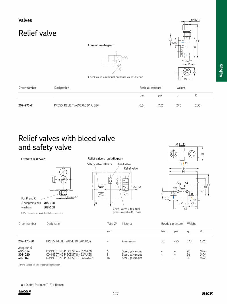
Valv
es
Valves
Relief valve
10
M10×11)
T
P
A
30
202-275-2
14
50
79
20
G1/4
G1/4
Order number Designation Residual pressure Weight
bar psi g lb
202-275-2 PRESS, RELIEF VALVE 0,5 BAR, G1/4 0,5 7.25 240 0.53
A
T
P
Connection diagram
Check valve = residual pressure valve 0 5 bar
A = Outlet; P = Inlet; T (R) = Return
Relief valves with bleed valve and safety valve
Order number Designation Tube ∅ Material Residual pressure Weight
mm bar psi g lb
202-175-30 PRESS RELIEF VALVE 30 BAR, R1/4 – Aluminium 30 435 570 1.26
Adaptors 1)
406-054 CONNECTING PIECE ST 6 - G1/4A ZN 6 Steel, galvanized – – 20 0.04301-020 CONNECTING PIECE ST 8 - G1/4A ZN 8 Steel, galvanized – – 16 0.04410-163 CONNECTING PIECE ST 10 - G1/4A ZN 10 Steel, galvanized – – 30 0.07
1) Ports tapped for solderless tube connection
A2
A1
40
84
80
6048
27
16
29
4367
25
12
A1A2
∅6
P R
G1/4
PR
A1, A2
Relief valve circuit diagram
Check valve = residual pressure valve 0 5 bars
M14×1.51)
Fitted to reservoir
For P and R
2 adapters each 408-160
washers 508-108
Bleed valve
Relief valve
Safety valve 30 bars
1) Ports tapped for solderless tube connection
127
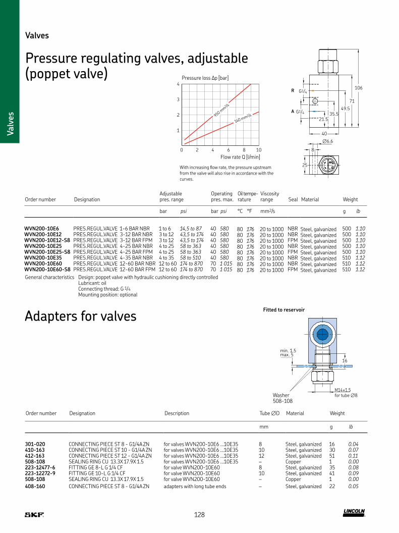
Valv
es
Valves
Pressure regulating valves, adjustable (poppet valve)
Order number DesignationAdjustable pres range
Operating pres max
Oil tempe- rature
Viscosity range Seal Material Weight
bar psi bar psi °C °F mm2/s g lb
WVN200-10E6 PRES REGUL VALVE 1-6 BAR NBR 1 to 6 14,5 to 87 40 580 80 176 20 to 1000 NBR Steel, galvanized 500 1.10WVN200-10E12 PRES REGUL VALVE 3-12 BAR NBR 3 to 12 43,5 to 174 40 580 80 176 20 to 1000 NBR Steel, galvanized 500 1.10WVN200-10E12-S8 PRES REGUL VALVE 3-12 BAR FPM 3 to 12 43,5 to 174 40 580 80 176 20 to 1000 FPM Steel, galvanized 500 1.10WVN200-10E25 PRES REGUL VALVE 4-25 BAR NBR 4 to 25 58 to 363 40 580 80 176 20 to 1000 NBR Steel, galvanized 500 1.10WVN200-10E25-S8 PRES REGUL VALVE 4-25 BAR FPM 4 to 25 58 to 363 40 580 80 176 20 to 1000 FPM Steel, galvanized 500 1.10WVN200-10E35 PRES REGUL VALVE 4-35 BAR NBR 4 to 35 58 to 510 40 580 80 176 20 to 1000 NBR Steel, galvanized 510 1.12WVN200-10E60 PRES REGUL VALVE 12-60 BAR NBR 12 to 60 174 to 870 70 1 015 80 176 20 to 1000 NBR Steel, galvanized 510 1.12WVN200-10E60-S8 PRES REGUL VALVE 12-60 BAR FPM 12 to 60 174 to 870 70 1 015 80 176 20 to 1000 FPM Steel, galvanized 510 1.12
General characteristics Design: poppet valve with hydraulic cushioning directly controlled Lubricant: oil Connecting thread: G 1/4
Mounting position: optional
106
71
R
A
G1/4
G1/4
40
∅6.6
8
25
49.5
35.5
21.5
M14×1.5
16
min. 1.5max. 5
Fitted to reservoir
Washer508-108
for tube ∅8
4
3
2
1
0 2 4 6 8 10
Pressure loss ∆p [bar]
Flow rate Q [l/min]
With increasing flow rate, the pressure upstream from the valve will also rise in accordance with the curves
950 mm
2 /s
140 mm2/s
Order number Designation Description Tube ∅D Material Weight
mm g lb
301-020 CONNECTING PIECE ST 8 - G1/4A ZN for valves WVN200-10E6 10E35 8 Steel, galvanized 16 0.04410-163 CONNECTING PIECE ST 10 - G1/4A ZN for valves WVN200-10E6 10E35 10 Steel, galvanized 30 0.07412-163 CONNECTING PIECE ST 12 - G1/4A ZN for valves WVN200-10E6 10E35 12 Steel, galvanized 51 0.11508-108 SEALING RING CU 13 3X 17 9X 1 5 for valves WVN200-10E6 10E35 – Copper 1 0.00223-12477-6 FITTING GE 8-L G 1/4 CF for valve WVN200-10E60 8 Steel, galvanized 35 0.08223-12272-9 FITTING GE 10-L G 1/4 CF for valve WVN200-10E60 10 Steel, galvanized 41 0.09508-108 SEALING RING CU 13 3X 17 9X 1 5 for valve WVN200-10E60 – Copper 1 0.00
408-160 CONNECTING PIECE ST 8 - G1/4A ZN adapters with long tube ends – Steel, galvanized 22 0.05
Adapters for valves
128

Valv
es
Valves
Pressure regulating valves, fixed pressure
L
12
R3/8
24
Order number Designation L MaterialOperating pressure max
Weight
mm bar psi g lb
624-25465-1 VALVE SV -120-G3/8A Z 88 Steel, galvanized 120 1 740 241 0.53624-25294-1 VALVE SV -350-G3/8A Z 84 Steel, galvanized 350 5 075 241 0.53624-27092-1 VALVE SV -410-G3/8A Z 82 Steel, galvanized 410 5 950 241 0.53
74
20
∅D
27
Order number DesignationPipe stud ∅D Material
Operating pressure max
Weight
mm bar psi g lb
624-25478-1 VALVE SVP -200-S 6 6 Steel, galvanized 200 2 900 237 0.52624-25479-1 VALVE SVP -350-S 6 6 Steel, galvanized 350 5 075 236 0.52624-25480-1 VALVE SVP -200-S 8 8 Steel, galvanized 200 2 900 240 0.53625-25481-1 VALVE SVP -350-S 8 8 Steel, galvanized 350 5 075 240 0.53624-25482-1 VALVE SVP -200-S 10 10 Steel, galvanized 200 2 900 240 0.53624-25483-1 VALVE SVP -350-S 10 10 Steel, galvanized 350 5 075 260 0.57
129

Valv
es
L1
D1 D120
Valves
Pressure regulating valves (ball valves)For flow rates from 0 5–2 l/min
50
7.4
M8×1D1 16
14
Order number Designation Tube ∅ D1 1)
Opening pressure Marking Material Weight
mm mm bar psi g lb
WVN200-4A0 4 PRES REGUL VALVE 0 4 BAR, ∅ 4 4 M8×1 0,4 5,8 0,4 Steel, galvanized 45 0.10WVN200-4A5 PRES REGUL VALVE 5 BAR, ∅ 4 4 M8×1 5 72,5 5 Steel, galvanized 47 0.10WVN200-4A8 PRES REGUL VALVE 8 BAR, ∅ 4 4 M8×1 8 116 8 Steel, galvanized 46 0.10WVN200-4A12 PRES REGUL VALVE 12 BAR, ∅ 4 4 M8×1 12 174 12 Steel, galvanized 45 0.10WVN200-4A16 PRES REGUL VALVE 16 BAR, ∅ 4 4 M8×1 16 232 16 Steel, galvanized 46 0.10WVN200-4A25 PRES REGUL VALVE 25 BAR, ∅ 4 4 M8×1 25 360 25 Steel, galvanized 46 0.10WVN200-4A0 4-S1 PRES REGUL VALVE 0 4 BAR, ∅ 6 6 M10×1 0,4 5,8 0,4 Steel, galvanized 48 0.11
1) Ports tapped for solderless tube connection
tap
Order number Designation Tube ∅ D1 1) L1
Opening pressure Marking Material Weight
mm mm mm mm bar psi g lb
WVN200-6B0 5 PRES REGUL VALVE 0,5 BAR, ∅ 6 6 M10×1 61 14 0,5 7,25 5 Steel, galvanized 57 0.13WVN200-6B3 PRES REGUL VALVE 3 BAR, ∅ 6 6 M10×1 61 14 3 43,5 3 Steel, galvanized 58 0.13WVN200-6B8 PRES REGUL VALVE 8 BAR, ∅ 6 6 M10×1 61 14 8 116 8 Steel, galvanized 58 0.13WVN200-6B12 PRES REGUL VALVE 12 BAR, ∅ 6 6 M10×1 61 14 12 174 12 Steel, galvanized 59 0.13WVN200-6B16 PRES REGUL VALVE 16 BAR, ∅ 6 6 M10×1 61 14 16 232 16 Steel, galvanized 60 0.13WVN200-6B20 PRES REGUL VALVE 20 BAR, ∅ 6 6 M10×1 61 14 20 290 20 Steel, galvanized 60 0.13WVN200-6B40 PRES REGUL VALVE 40 BAR, ∅ 6 6 M10×1 61 14 40 580 40 Steel, galvanized 59 0.13WVN200-8B0 PRES REGUL VALVE 0 04 BAR, ∅ 8 8 M14×1,5 71 17 0,04 0,58 0 Steel, galvanized 86 0.19WVN200-8B3 PRES REGUL VALVE 3 BAR, ∅ 8 8 M14×1,5 71 17 3 43,5 3 Steel, galvanized 87 0.19WVN200-8B5 PRES REGUL VALVE 5 BAR, ∅ 8 8 M14×1,5 71 17 5 72,5 5 Steel, galvanized 89 0.20WVN200-8B12 PRES REGUL VALVE 12 BAR, ∅ 8 8 M14×1,5 71 17 12 174 12 Steel, galvanized 89 0.20WVN200-8B16 PRES REGUL VALVE 16 BAR, ∅ 8 8 M14×1,5 71 17 16 232 16 Steel, galvanized 84 0.19WVN200-8B20 PRES REGUL VALVE 20 BAR, ∅ 8 8 M14×1,5 71 17 20 290 20 Steel, galvanized 90 0.20WVN200-8B32 PRES REGUL VALVE 32 BAR, ∅ 8 8 M14×1,5 71 17 32 464 32 Steel, galvanized 93 0.21WVN200-10B0 PRES REGUL VALVE 0 04 BAR, ∅ 10 10 M16×1,5 80 19 0,04 0,58 0 Steel, galvanized 100 0.22WVN200-10B0 5 PRES REGUL VALVE 0 5 BAR, ∅ 10 10 M16×1,5 80 19 0,5 7,25 5 Steel, galvanized 126 0.28WVN200-10B1 PRES REGUL VALVE 12 BAR, ∅ 10 10 M16×1,5 80 19 1,2 17,4 12 Steel, galvanized 128 0.28WVN200-10B32 PRES REGUL VALVE 32 BAR, ∅ 10 10 M16×1,5 80 19 32 464 32 Steel, galvanized 130 0.29161-212-054 2) PRES REGUL VALVE 20 BAR, ∅ 8 10 M14×1,5 84,5 17 20 290 20 Steel, galvanized 107 0.24
1) Ports tapped for solderless tube connection2) This valve is designed as a plunger valve Because of this design it can also be used for regulating tasks whereas the ball valves should be used as safety valves
130

Valv
es
Valves
Pressure regulating valves (ball valves)For flow rates from 0 5–2 l/min
6
~64
20
M14×1.5
19
M10×11)
45
17
19
14
Order number Designation p max Max temperature Material Weight
bar psi °C °F g lb
202-085-S SHUT-OFF VALVE 60 BAR, M14×1 5 60 810 80 176 Steel, galvanized 110 0.24
Direction of flow optional
L1
D120
17
17
D
Order number Designation Tube ∅ L1 Opening pressure Marking Material Weight
mm mm bar psi g lb
WVN200-8D50 PRES REGUL VALVE 50 BAR, ∅ 8 8 84 50 725 50 Steel, galvanized 130 0.29WVN200-8D75 PRES REGUL VALVE 75 BAR, ∅ 8 8 84 75 1 090 75 Steel, galvanized 135 0.30WVN200-8D120 PRES REGUL VALVE 120 BAR, ∅ 8 8 84 120 1 740 120 Steel, galvanized 130 0.29WVN200-8D220 PRES REGUL VALVE 220 BAR, ∅ 8 8 84 220 3 190 220 Steel, galvanized 130 0.29WVN200-10D120-S1 PRES REGUL VALVE 120 BAR, ∅ 10 10 87 120 1 740 120 Steel, galvanized 140 0.31WVN200-10D220-S1 PRES REGUL VALVE 220 BAR, ∅ 10 10 87 220 3 190 220 Steel, galvanized 135 0.30
Cutting sleeve screw unions according to DIN 2353
Shut-off valves
131

Valv
es
Order number Designation p max Connection Nominal ∅ DN Material Weight
bar psi mm g lb
235-13108-4 BALL VALVE ST G 1/2I DN13 500 BAR 500 7 250 G 1/2 female 13 Steel, galvanized 640 1.41235-13114-1 BALL VALVE ST D20 DN16 400 BAR 400 5 800 Tube ∅ 20 16 Steel, galvanized 960 2.12
Direction of flow optional
10
40
27.5
G1/4
21
161-600-036
25
G1/2
13
13
49
∅10
G1/2
46UFZ 0097
Order number Designation p max Max temperature Material Weight
bar psi °C °F g lb
161-600-036 BALL VALVE BRASS, G1/4 I, 16 BAR 16 232 90 194 Brass 80 0.18UFZ 0097 BALL VALVE BRASS, G1/2 I, 10 BAR 10 145 90 194 Brass 150 0.33
Direction of flow optional
Valves
Shut-off valves
132

Valv
es
Valves
Solenoid valves147
15
30
0
CB
55
C
A
125
VP1Z A
A
C
B
A
Order number Designation Type Off Position Operating voltage
Con-nection
p max Weight
bar psi g lb
525-32080-1 WAY VALVE WV-M-W2G-1/2- 24DC 2/2 way valve normally closed 24 VDC G 1/2 400 5 800 1,74 3.84525-32082-1 WAY VALVE WV-M-W2G-1/2-230AC 2/2 way valve normally closed 230 VAC G 1/2 400 5 800 1,7 3.75525-32081-1 WAY VALVE WV-M-W2G-1/2-110AC 2/2 way valve normally closed 110 VAC G 1/2 400 5 800 1,76 3.88525-32083-1 WAY VALVE WV-M-W2O-1/2- 24DC 2/2 way valve normally open 24 VDC G 1/2 400 5 800 1,76 3.88525-32084-1 WAY VALVE WV-M-W2O-1/2-230AC 2/2 way valve normally open 230 VAC G 1/2 400 5 800 1,69 3.73525-32098-1 WAY VALVE WV-M-W2O-1/2-110AC 2/2 way valve normally open 110 VAC G 1/2 400 5 800 1,81 3.99525-32085-1 WAY VALVE WV-M-W3 -3/8- 24DC 3/2 way valve – 24 VDC G 3/8 400 5 800 1,37 3.02525-32087-1 WAY VALVE WV-M-W3 -3/8-230AC 3/2 way valve – 230 VAC G 3/8 400 5 800 1,3 2.87525-32086-1 WAY VALVE WV-M-W3 -3/8-110AC 3/2 way valve – 110 VAC G 3/8 400 5 800 1,38 3.04161-110-031+924 WAY VALVE WV-M-W2G-1/4- 24DC 2/2 way valve normally closed 24 VDC G 1/4 500 7 250 1,28 2.82161-120-064+924 WAY VALVE WV-M-W3 -1/4- 24DC 3/2 way valve – 24 VDC G 1/4 500 7 250 1,25 2.76
Socket box DIN EN 175301-803 or 179-990-416 (with LED, protective circuit) has to be ordered separately
Swivels 180° or 22,5°Manual actuation
133

Pressure gauges
Description
Pressure gauges are mechanically operated instruments that
visually display the pressure of the connected medium In lubrication
systems, they are used to show the pressure rate of air, oil or grease
of either the pump or the pipe system They are available in various
pressure ranges for low-, medium- or high-pressure applications in
all kinds of lubrication systems
The following points must be considered in order to select
the correct model:
• Pressure of the medium – the maximum pressure that could occur in the system shall not be higher than 2/3 of the indication range of the pressure range
• Pulsation of the pressure – use of liquid-filled gauges is highly recommended for measuring points with high dynamic pressure loads and areas with vibration
• Corrosive atmosphere – use of stainless steel pressure gauges is highly recommended
• If an electrical signal is desired – use of pressure gauges,
including digital pressure indication, is highly recommended
Features and benefits
• Visual and digital pump and system pressure monitoring
• Economical, reliable and virtually maintenance-free operation
• Wide range of pressure rates and sizes
• Liquid-filled gauges for dynamic operations available
• Stainless for operation in aggressive atmosphere available
Applications
• All kinds of lubrication systems: low, middle mechanic and plant engineering
• Oil and grease lubrication systems
• Installation at the pump or at the end of the line
Pre
ssure
gauges
134

Pre
ssure
gauges
Damped pressure gauges with restrictor
75
40
27
∅ 8
Order number Designation Restrictor Lubricant Indication range Material Weight
mm bar psi g lb
248-602 25 PR GAUGE D40 0-10 BAR TUBE 8 4kt 12 – – 0–10 0–145 Steel housing, black 66 0.15169-102-506 1) PR GAUGE D40 0-25 BAR TUBE 8 12 0,4 – 0–25 0–360 Steel housing, black 62 0.14248-602 20 PR GAUGE D40 0-40 BAR TUBE 8 12 – Grease 0–40 0–580 Steel housing, black 59 0.13169-104-008 1) PR GAUGE D40 0-40 BAR TUBE 8 4kt 14 0,4 Oil 0–40 0–580 Steel housing, black 61 0.13169-106-004 PR GAUGE D40 0-60 BAR TUBE 8 ABS 4kt 14 – – 0–60 0–870 ABS housing 60 0.13
Fixed by means of a double-tapered sleeve and socket union (solderless tube connection) in counterbore acc to DIN 3854/DIN 3862
1) damped design
Pressure gauges
Standard pressure gauges
MPapsibar
62
G1/4B
84.5
14
Order number Designation Indication range Material Weight
bar psi g lb
169-101-004 PR GAUGE D63 0-10 BAR G1/4 ABS 0–10 0–145 ABS housing 96 0.21169-102-020 2) PR GAUGE D63 0-25 BAR G1/4 ABS 0–25 0–360 ABS housing 90 0.20169-104-020 2) PR GAUGE D63 0-40 BAR G1/4 ABS 0–40 0–580 ABS housing 100 0.22169-106-020 2) PR GAUGE D63 0-60 BAR G1/4 ABS 0–60 0–870 ABS housing 83 0.18169-110-020 2) PR GAUGE D63 0-100 BAR G1/4 ABS 0–100 0–1 450 ABS housing 90 0.20169-116-000 PR GAUGE D63 0-160 BAR G1/4 ABS 0–160 0–2 320 ABS housing 94 0.21169-125-020 2) PR GAUGE D63 0-250 BAR G1/4 ABS 0–250 0–3 625 ABS housing 84 0.19
Washer, order No 248-610 02, must be ordered separately for use in solderless tube connections acc to DIN 3862
2) Associated connecting pieces → page 60
135
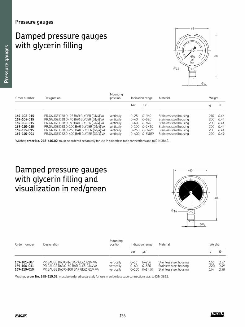
Pre
ssure
gauges
Pressure gauges
Damped pressure gauges with glycerin filling
MPapsibar
68
G1/4
88
14
Order number DesignationMounting position Indication range Material Weight
bar psi g lb
169-102-015 PR GAUGE D68 0- 25 BAR GLYCER (G1/4) VA vertically 0–25 0–360 Stainless steel housing 210 0.46169-104-015 PR GAUGE D68 0- 40 BAR GLYCER (G1/4) VA vertically 0–40 0–580 Stainless steel housing 200 0.44169-106-015 PR GAUGE D68 0- 60 BAR GLYCER (G1/4) VA vertically 0–60 0–870 Stainless steel housing 200 0.44169-110-015 PR GAUGE D68 0-100 BAR GLYCER (G1/4) VA vertically 0–100 0–1 450 Stainless steel housing 200 0.44169-125-015 PR GAUGE D68 0-250 BAR GLYCER (G1/4) VA vertically 0–250 0–3 625 Stainless steel housing 200 0.44169-140-001 PR GAUGE D62 0-400 BAR GLYCER (G1/4) VA vertically 0–400 0–5 800 Stainless steel housing 220 0.49
Washer, order No 248-610 02, must be ordered separately for use in solderless tube connections acc to DIN 3862
Damped pressure gauges with glycerin filling and visualization in red/green
G1/4
~63
~84
14
Order number DesignationMounting position Indication range Material Weight
bar psi g lb
169-101-607 PR GAUGE D63 0-16 BAR GLYZ G1/4 VA vertically 0–16 0–230 Stainless steel housing 166 0,37169-106-011 PR GAUGE D63 0-60 BAR GLYZ G1/4 VA vertically 0–60 0–870 Stainless steel housing 220 0,49169-110-010 PR GAUGE D63 0-100 BAR GLYZ G1/4 VA vertically 0–100 0–1 450 Stainless steel housing 174 0,38
Washer, order No 248-610 02, must be ordered separately for use in solderless tube connections acc to DIN 3862
136

Pre
ssure
gauges
Pressure gauges
High-pressure gauges
0
100
200
300
400
500
600
bar
G
∅D
H
Order number Designation ∅D G HMounting position Indication range Material Weight
mm mm mm bar psi g lb
Steel housing, black234-13132-7 PR GAUGE D 63 0- 400 BAR GLYZ G1/4B BOT 63 G 1/4 bottom 84,5 vertically 0-400 0-5800 Steel housing, black 200 0,44234-13132-8 PR GAUGE D 63 0- 400 BAR G1/4 63 G 1/4 bottom 84,5 vertically 0-400 0-5800 Steel housing, black 100 0,22234-13156-6 PR GAUGE D 63 0- 600 BAR (G1/4A) 63 G 1/4 bottom 84,5 vertically 0-600 0-8700 Steel housing, black 210 0,46234-13182-7 PR GAUGE D 63 0- 600 BAR GLYZ G1/4B BOT 63 G 1/4 bottom 84,5 vertically 0-600 0-8700 Steel housing, black 200 0,44234-10396-2 PR GAUGE D100 0- 400 BAR (G1/2A) 100 G 1/2 bottom 133 vertically 0-400 0-5800 Steel housing, black 601 1,33234-13101-2 PR GAUGE D100 0- 600 BAR (R1/2) 100 G 1/2 bottom 133 vertically 0-600 0-8700 Steel housing, black 560 1,23234-13101-4 PR GAUGE D100 0- 600 BAR GLYZER 100 G 1/2 bottom 133 vertically 0-600 0-8700 Steel housing, black 860 1,90
Stainless steel housing234-10396-9 PR GAUGE D 63 0- 400 BAR G1/4(BAR/PSI)VA 63 G 1/4 bottom 84,5 vertically 0-400 0-5800 Stainless steel housing 200 0,44234-13182-8 PR GAUGE D 63 0- 400BAR G1/4B BACK VA 63 G 1/4 back 63 vertically 0-400 0-5800 Stainless steel housing 220 0,49234-10898-4 PR GAUGE D100 0- 400 BAR+PSI GLYZ 1 4404 100 G 1/2 bottom 133 vertically 0-400 0-5800 Stainless steel housing 993 2,19234-13136-2 PR GAUGE D100 0- 600 BAR HOUSING VA 100 G 1/2 bottom 133 vertically 0-600 0-8700 Stainless steel housing 600 1,32
137

Reservoirs
Description
For technical reasons, all reservoirs shown in this catalogue can
only be used for oil Grease reservoirs require additional technical
features that make a combination of reservoir and pump necessary
The reservoirs shown are available in either plastic or metal designs
The advantage of the plastic containers is that the oil filling level is
clearly visible through the transparent reservoir Metal reservoirs
from 6 liters (1.5 gal) and larger can be equipped with external oil
level indicators It is also possible to monitor the minimum or maxi-
mum oil level electrically via float switches Depending on the oil
used, the sealing material (NBR or FPM) should be selected
Features and benefits
• Available in sizes ranging from 3 litres to 100 litres on request
• All reservoirs are equipped with a screen at the filler socket
(exception: 1 litre tank screen at the outlet), which reliably
prevents foreign particles from entering
• Simple and proven design for use in all kinds of automatic
oil lubrication systems
• Virtually leakage-free storage of oil
• Easy manual or digital fill-level monitoring
Applications
• All automatic oil lubrication systems
• Pulp and paper industry
• Automobile presses
• Food and beverage
• Automation
• Printing
• Metals
• Etc
Res
ervo
irs
and t
rays
138

Res
ervo
irs
and t
rays
Reservoirs
Plastic reservoirs
∅8.5 (2x)
1080
3
36
117
M14×1.51)
247
2550
∅113
WS
Order number DesignationReservoir Capacity Level indicator WS Type of contact
Seal material Weight
l gal. kg lb
K1 OIL RESERVOIR ASSY KF 1YN 1 0.26 – – NBR 0,70 1.54KW1 OIL RESERVOIR ASSY KF 1YL (NO) 1 0.26 Min filling level NO NBR 0,76 1.68KW1-S2 OIL RESERVOIR ASSY KF 1YL (NC) 1 0.26 Min filling level NC NBR 0,80 1.76
1) Ports tapped for solderless tube connection
for tube ∅10
212
16 90
(3x) 8.5
0
7
35
~ 20069
M16×1.51)
0 66 13090
290
145
110
WS (3x) 8.5228
183
20
0
178
98M16×1.51)
128
15
110
Order number DesignationReservoir Capacity Level indicator WS Type of contact
Seal material Weight
l gal. kg lb
K3-S2 OIL RESERVOIR ASSY KF 3YN 3 0.79 – – NBR 1,34 2.95KW3-S1 OIL RESERVOIR ASSY KF 3YL (SPDT) 3 0.79 Min filling level Changeover NBR 1,63 3.59K6-S5 FLUID GREASE RESERVOIR ASSY KF 6YN 6 1.58 – – NBR 2,28 5.04K6-S6 OIL RESERVOIR ASSY KF 6YN 6 1.58 – – NBR 2,28 5.04KW6-S1 OIL RESERVOIR ASSY KF 6YL (SPDT) 6 1.58 Min filling level Changeover NBR 2,58 5.70KW6-S2 OIL RESERVOIR ASSY KF 6YLP (NC) 6 1.58 Min filling with advance warning 2NCs NBR 2,50 5.51KW6-S81 OIL RESERVOIR ASSY KF 6YL (SPDT) 6 1.58 Min filling level Changeover FPM 2,58 5.70
Plastic reservoir, 3 liter
for tube ∅10
Return G1/2
Filler socket with screen
Plastic reservoir, 6 liter
for tube ∅10
Filler socket with screen
1) Ports tapped for solderless tube connection 1) Ports tapped for solderless tube connection
139

Res
ervo
irs
and t
rays
Reservoirs
Plastic reservoirs
G3/4
160 20∅10
330
170850
361
870
255
10
55
G3/4
80 20∅10
330
170340
361
Order number DesignationReservoir Capacity Level indicator WS Type of contact Weight
l gal. kg lb
651-28691-1 OIL RESERVOIR PL 13YL F PMA 13 2.86 Minimum filling level Changeover 2,2 4.85651-29124-1 OIL RESERVOIR PL 13YN F PMA 13 2.86 – – 2 4.40
651-28685-1 OIL RESERVOIR PL 36YL F PMA 36 7.9 Minimum filling level Changeover 4,251 9.37
Oil trough with shut-off valve
Order number DesignationReservoir Capacity
L B H
l gal.
B3 U21 OIL TROUGH 3L 3 0,792 350 280 140B7 U271 OIL TROUGH 6L 6 1,585 400 380 190
L B
H
140
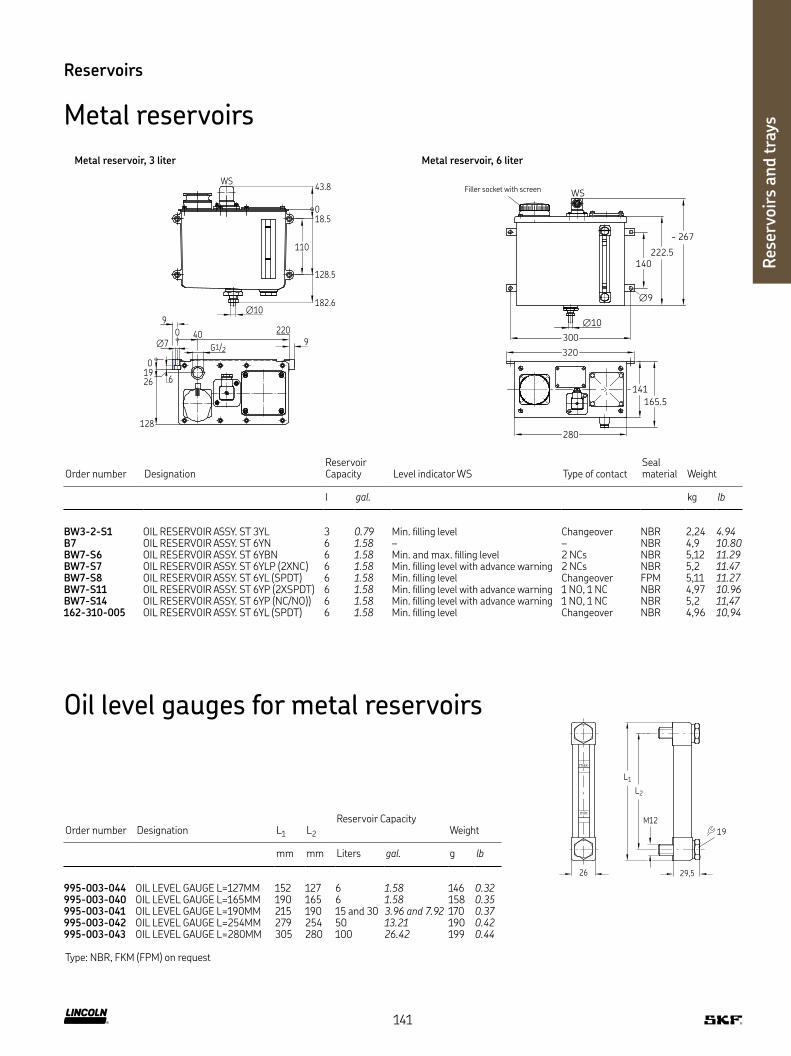
Res
ervo
irs
and t
rays
Reservoirs
Metal reservoirs
6
∅7
1926
0
128
G1/2
43.8
018.5
128.5
182.6
110
WS
∅10
9
220400
9
140
222.5
~ 267
WS
141
165.5
280
300
320
∅9
∅10
Order number DesignationReservoir Capacity Level indicator WS Type of contact
Seal material Weight
l gal. kg lb
BW3-2-S1 OIL RESERVOIR ASSY ST 3YL 3 0.79 Min filling level Changeover NBR 2,24 4.94B7 OIL RESERVOIR ASSY ST 6YN 6 1.58 – – NBR 4,9 10.80BW7-S6 OIL RESERVOIR ASSY ST 6YBN 6 1.58 Min and max filling level 2 NCs NBR 5,12 11.29BW7-S7 OIL RESERVOIR ASSY ST 6YLP (2XNC) 6 1.58 Min filling level with advance warning 2 NCs NBR 5,2 11.47BW7-S8 OIL RESERVOIR ASSY ST 6YL (SPDT) 6 1.58 Min filling level Changeover FPM 5,11 11.27BW7-S11 OIL RESERVOIR ASSY ST 6YP (2XSPDT) 6 1.58 Min filling level with advance warning 1 NO, 1 NC NBR 4,97 10.96BW7-S14 OIL RESERVOIR ASSY ST 6YP (NC/NO)) 6 1.58 Min filling level with advance warning 1 NO, 1 NC NBR 5,2 11,47162-310-005 OIL RESERVOIR ASSY ST 6YL (SPDT) 6 1.58 Min filling level Changeover NBR 4,96 10,94
Metal reservoir, 3 liter Metal reservoir, 6 liter
Filler socket with screen
M12
29,5
max
min
26
19
L1
L2
Order number Designation L1 L2
Reservoir CapacityWeight
mm mm Liters gal. g lb
995-003-044 OIL LEVEL GAUGE L=127MM 152 127 6 1.58 146 0.32995-003-040 OIL LEVEL GAUGE L=165MM 190 165 6 1.58 158 0.35995-003-041 OIL LEVEL GAUGE L=190MM 215 190 15 and 30 3.96 and 7.92 170 0.37995-003-042 OIL LEVEL GAUGE L=254MM 279 254 50 13.21 190 0.42995-003-043 OIL LEVEL GAUGE L=280MM 305 280 100 26.42 199 0.44
Type: NBR, FKM (FPM) on request
Oil level gauges for metal reservoirs
141

Lubri
cati
ng n
ipple
s
Lubricating nipples
Description
Grease nipples provide a standardized connection to the grease gun
and are therefore an important part for servicing and maintaining
bearings They also protect the lubrication point from external
influences such as dirt and water
Features and benefits
• Our standard program includes the most common hydraulic
and flat grease nipples according to DIN 74412 and DIN 3404
• Available in galvanized steel or stainless steel
Applications
• Linear guides
• Bearings, bearing blocks
• Drive shafts, cardan shafts
• Axles
142

Lubri
cati
ng n
ipple
s
Lubricating nipples
Hydraulic grease nipples according to DIN 71412
Button-head grease nipples according DIN 3404
Order number Designation Form Thread MaterialOperating pressure max Weight
(100 pcs)
mm bar psi g lb
Steel, galvanized251-14040-1 HYDRAULIC LUBR FITT ST AR 1/8 Z Straight R 1/8 11 Steel, galvanized 350 5 080 600 1.32996-001-890 HYDRAULIC LUBR FITT ST AM 10X1,0 Z Straight M10×1 11 Steel, galvanized 350 5 080 500 1.10251-14109-3 HYDRAULIC LUBR FITT ST BR 1/4 Z Angle, 45° R 1/4 14 Steel, galvanized 350 5 080 1 800 3.97251-14045-1 HYDRAULIC LUBR FITT ST BR 1/8 Z Angle, 45° R 1/8 11 Steel, galvanized 350 5 080 1 200 2.65251-14040-2 HYDRAULIC LUBR FITT ST CR 1/8 Z Angle, 90° R 1/8 11 Steel, galvanized 350 5 080 1 200 2.65251-14044-8 HYDRAULIC LUBR FITT ST CR 1/4 Z Angle, 90° R 1/4 14 Steel, galvanized 350 5 080 1 200 2.65
Stainless steel251-14073-9 HYDR LUBR FITT +CHECK VALVE A2 1/8 Straight R 1/8 11 Stainless steel 400 5 800 800 1.76251-14109-2 HYDRAULIC LUBR FITT A2 AR 1/8 Z Straight R 1/8 11 Stainless steel 350 5 080 600 1.32251-10309-1 HYDRAULIC LUBR FITT A2 AR 1/4 Z Straight R 1/4 14 Stainless steel 350 5 080 1 200 2.65251-10780-2 HYDRAULIC LUBR FITT A2 AM 10X1,0 Z Straight M10×1 11 Stainless steel 350 5 080 500 1.10251-14063-4 HYDRAULIC LUBR FITT A2 BR 1/8 Z Angle, 45° R 1/8 11 Stainless steel 350 5 080 1 200 2.65251-14063-9 HYDRAULIC LUBR FITT A2 CR 1/8 Z Angle, 90° R 1/8 11 Stainless steel 350 5 080 1 200 2.65
Order number Designation Head ∅ Thread MaterialOperating pressure max Weight
(100 pcs)
mm mm bar psi g lb
251-14040-5 BUTTON HEAD LUBR FITT ST AG 1/8-16Z 16 G 1/8 17 Steel, galvanized 350 5 800 1 700 3.75251-14040-4 BUTTON HEAD LUBR FITT ST AG 1/4-16Z 16 G 1/4 17 Steel, galvanized 350 5 800 1 900 4.19251-10309-2 BUTTON HEAD LUBR FITT ST AG 3/8-16Z 16 G 3/8 17 Steel, galvanized 350 5 800 2 000 4.41251-14063-1 BUTTON HEAD LUBR FITT ST AG 1/4-22Z 22 G 1/4 22 Steel, galvanized 350 5 800 4 000 8.82251-14040-3 BUTTON HEAD LUBR FITT ST AG 3/8-22Z 22 G 3/8 22 Steel, galvanized 350 5 800 4 000 8.82251-14045-8 BUTTON HEAD LUBR FITT ST AM10X1,0-16Z 16 M10×1 22 Steel, galvanized 350 5 800 1 700 3.75
L1
L2
L3
GW
L1
∅22 mm
L2
GW
L1
L2
GW
WL
W
L1
L2
GW
WL
W
Straight Angle, 45° Angle, 90°
Head
Thread
Thread ThreadThread
143

Lubri
cati
ng n
ipple
s
∅6.4 L1
L2
5
32
Ȃ51
20
6
Order number DesignationPorts for lubricating nipples
L1 L2 MaterialOperating pressure max
Weight (100 pcs)
mm mm bar psi g lb
532-32248-1 LUBR FITT BLOCK W 1 FITT R1/8 45 DEGREE 1 30 40 Steel, galvanized 400 5 800 160 0.35504-37184-2 LUBR FITT BLOCK W 1 FITT R1/4" 90 DEGREE 1 30 40 Steel, galvanized 400 5 800 217 0.48504-37210-1 LUBR FITT BLOCK 2 FITT R1/8 2 40 50 Steel, galvanized 400 5 800 132 0.29504-37211-1 LUBR FITT BLOCK 3 FITT R1/8 3 60 70 Steel, galvanized 400 5 800 177 0.39532-32454-1 LUBR FITT BLOCK W 2 FITT R1/8 2 40 50 Steel, galvanized 400 5 800 331 0.73432-70024-1 LUBR FITT BLOCK 2 CONN R1/8 HORIZ /VERTIC 2 1) 40 50 Steel, galvanized 400 5 800 236 0.52
1) 2 lubricating nipple connections; corresponding tapered grease nipple order no 251-14045-1
25
30
L2
L1
∅6.4
∅6
30 ∅9
Ȃ75
9
Lubricating nipples
Lubrication fitting block
Order number DesignationProts for lubricating nipples L1 Material
Operating pressure max
Weight (100 pcs)
mm bar psi g lb
532-32131-1 HOLDER W HYDR LUBR FITTING 1 40 Steel, galvanized 400 5 800 93 0.21
Holder with lubricating nipple and fitting
532-32248-1 532-32454-1
144
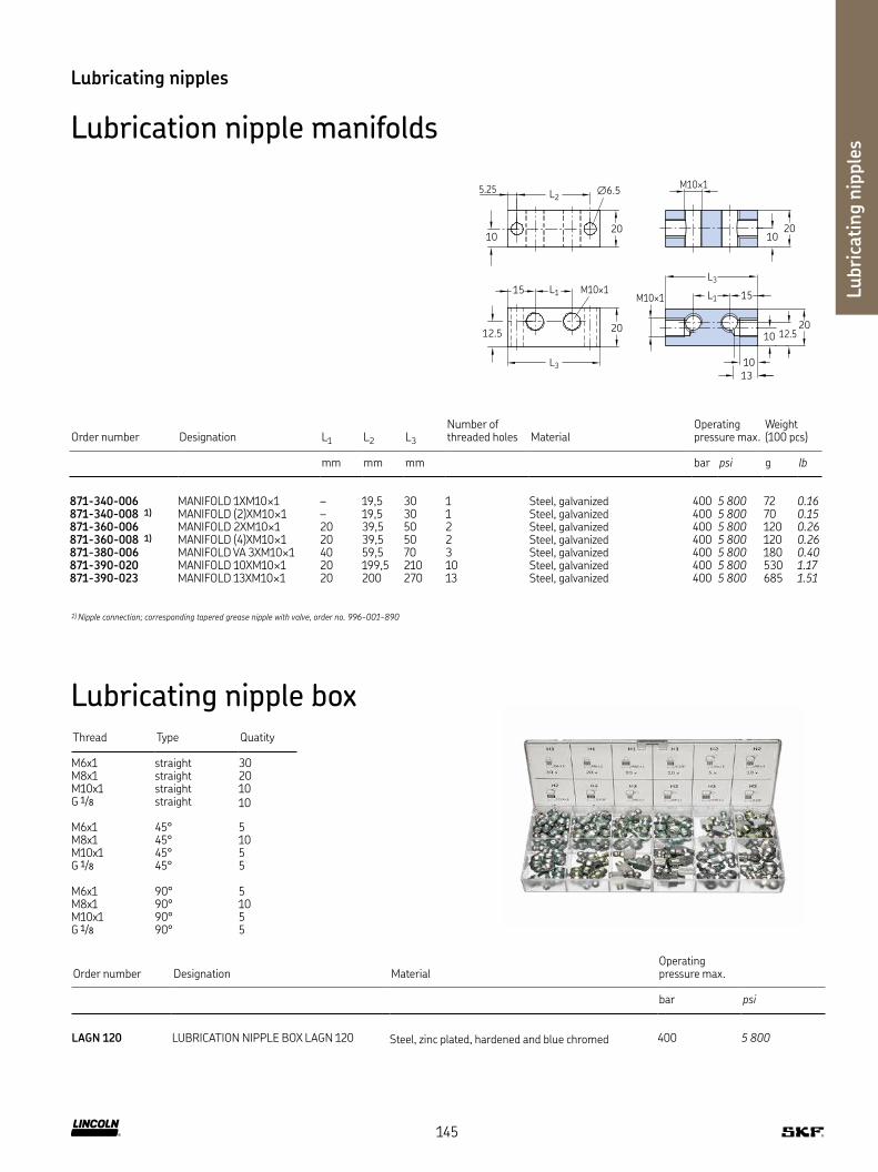
Lubri
cati
ng n
ipple
s
Lubricating nipples
Lubrication nipple manifolds
10
13
15L1
L3
10
20
M10×1
M10×1
1020
12.5
L25.25 ∅6.5
1020
15 L1 M10×1
L3
12.520
Order number Designation L1 L2 L3
Number of threaded holes Material
Operating pressure max
Weight (100 pcs)
mm mm mm bar psi g lb
871-340-006 MANIFOLD 1XM10×1 – 19,5 30 1 Steel, galvanized 400 5 800 72 0.16871-340-008 1) MANIFOLD (2)XM10×1 – 19,5 30 1 Steel, galvanized 400 5 800 70 0.15871-360-006 MANIFOLD 2XM10×1 20 39,5 50 2 Steel, galvanized 400 5 800 120 0.26871-360-008 1) MANIFOLD (4)XM10×1 20 39,5 50 2 Steel, galvanized 400 5 800 120 0.26871-380-006 MANIFOLD VA 3XM10×1 40 59,5 70 3 Steel, galvanized 400 5 800 180 0.40871-390-020 MANIFOLD 10XM10×1 20 199,5 210 10 Steel, galvanized 400 5 800 530 1.17871-390-023 MANIFOLD 13XM10×1 20 200 270 13 Steel, galvanized 400 5 800 685 1.51
1) Nipple connection; corresponding tapered grease nipple with valve, order no. 996-001-890
Order number Designation MaterialOperating pressure max
bar psi
LAGN 120 LUBRICATION NIPPLE BOX LAGN 120 Steel, zinc plated, hardened and blue chromed 400 5 800
Lubricating nipple box Thread Type Quatity
M6x1 straight 30M8x1 straight 20M10x1 straight 10G 1/8 straight 10
M6x1 45° 5M8x1 45° 10M10x1 45° 5G 1/8 45° 5
M6x1 90° 5M8x1 90° 10M10x1 90° 5G 1/8 90° 5
145

Filte
rs
Filters
Description
These easy-to-service lubricant filters consist of a housing and an
integrated screen Grease filters have pressure ratings up to 400 bar
(5800 psi) and allow flow rates up to 24 dm3/hour (6 3 US gal/hour),
oil and fluid grease filters allow 2 l/min
Galvanized and chromate-treated lubricant filter units are available
with hydraulic lubrication fittings for lubrication pump reservoir fill-
ing They are also suitable for upstream installation in lubrication
systems with divider valves and for outlet connection with outside
diameters of 6 mm
Features and benefits
• Prevents system or component failures and extends system life to
significant reduction of solids
• Economical, reliable and maintenance-friendly operation
• Compact and modular design mountable directly into pipes
• Wide range of volumetric flow levels and grades of filtration
• Optimized service handling by replacing of filter elements only
• Dirt monitoring of filter elements as an option
• Oil, fluid grease and grease filters
Applications
• General mechanic and plant engineering
• Ship building and offshore industry
• Pulp and paper industry
• Heavy industry
146

Filte
rs
Filters
Screen filters for oil and fluid grease
Order number Designation Lubricant Filter rating Connection thread MaterialOperating pressure max Weight
µm bar psi kg lb
213-870 FILTER FLUID GREASE NLGI CLASS 000, 00 63 G 1/4 Aluminum 60 870 0,31 0.68213-870F* FILTER FLUID GREASE NLGI CLASS 000, 00 160 G 1/4 Aluminum 60 870 0,31 0.68213-880 FILTER OIL 25 G 1/4 Aluminum 60 870 0,31 0.68213-930F FILTER FLUID GREASE NLGI CLASS 000, 00 160 G 1/4 Aluminum 60 870 1,27 2.80
32
∅5.5
∅19
5012 22
0
10
25
50
88
540
MDmax 20 Nm
G1/4G1/4
13
Filter elements for oil and fluid grease filters
Order number Designation Lubricant Filter ratingOperating pressure max
µm bar psi
213-870 U1 FILTER ELEMENT FOR 213-870 Fluid grease NLGI class 000, 00 63 60 870213-870 U2 FILTER ELEMENT FOR 213-870F Fluid grease NLGI class 000, 00 160 60 870213-880 U1 FILTER ELEMENT FOR 213-880 Oil 25 60 870213-870 U2 FILTER ELEMENT FOR 213-930F Fluid grease NLGI class 000, 00 160 60 870
147

Filte
rs
Filters
Screen filters for grease
Order number Designation Tube ∅D Thread MaterialOperating pressure max Weight
mm bar psi g lb
628-36062-3 Type SF 1-G 1/4 + 90° Nipple – G 1/4 Steel, galvanized 350 5 080 540 1.19628-26452-2 Type SF 1-G 1/4 – G 1/4 Steel, galvanized 350 5 080 440 0.97428-21544-1 Coarse strainer (replacement part) – – Steel, galvanized 350 5 080 2 0.005528-36045-6 Filter unit with nipple and tube connection 6 – Steel, galvanized 350 5 080 1 400 3.09528-31341-3 Filter unit G 1/4 female – G 1/4 Steel, galvanized 350 5 080 1 280 2.82628-25531-2 Filter unit G 3/8 female – G 3/8 Steel, galvanized 350 5 080 2 470 5.45
30
15
48
60
G1/4
(2x)∅7
∅6.6
3910.5
45
60
80
47
R3/8~R3/8~
95
628-36062-3 628-25531-2
528-36045-6
148

Filte
rs
Order number DesignationItem number Material
Operating pressure max Weight
bar psi g lb
428-21543-2 Hollow screw 1 Steel, galvanized 350 5 080 284 0.63428-21544-1 Coarse strainer, fineness of filtration 410 µm 2 Brass 350 5 080 2 0.005428-21546-2 Spacing ring 3 Spring steel 350 5 080 2 0.005428-21545-1 Fine strainer, fineness of filtration 270 µm 4 Brass 350 5 080 2 0.005303-17546-1 Threaded ring 5 Steel 350 5 080 12 0.03220-12238-3 Usit sealing ring 6 NBR 350 5 080 7 0.02
Grease filter accessories
Filter elements for grease filter units
2 3 4 5 61
∅16G3/4
44
27
22
149

Brushes
Description
Brush applicators are an easy, inexpensive and reliable solution
for many lubrication applications By using brush chain lubrication,
the entire conveyor chain is lubricated, not just the joints of the chain
links Standard lubricating oil, such as highly viscous chain oil, can be
applied with brushes as can fluid grease
Features and benefits
• Lubrication with a brush for chain speeds up 6 m / min
• Switching off and on individual chain lubrication systems possible
• Accurate dosage, regardless of oil viscosity and flow resistance
• High working pressure of the lubrication metering device enables
targeted oil emissions
• Lubrication without the addition of costly compressed air
Applications
• Ovens, boilers, dryers
• Freezers
• Conveyors for sorting, cleaning, cooking
and pasteurizing fruits and vegetables
• Dryers, smokers and conveyors for meat processing
• Conveyors for material transport
Bru
shes
150

Bru
shes
Order number Designation ShapeTube ∅D
Shape size Temperature Material Fixation Weight
mm °C °F mm g lb
UC-1066-01 OIL BRUSH BRISTLE, 55X16 Rectangle 4 mm 55×16 10 to 60 50 to 140 Bristle ∅8,5 110 0.24UC-1066-02 OIL BRUSH MS, 55X16 Rectangle 4 mm 55×16 10 to 200 50 to 392 Brass ∅8,5 160 0.35UC-1066-03 OIL BRUSH BRISTLE, D30 Circle 4 mm ∅30 10 to 60 50 to 140 Bristle ∅19 85 0.19UC-1066-04 OIL BRUSH BRISTLE, D15 Circle 4 mm ∅15 10 to 60 50 to 140 Bristle ∅12,5 45 0.10UC-1066-05 OIL BRUSH PA6, D15 Circle 4 mm ∅15 10 to 80 50 to 176 Polyamide 6 6 ∅12,5 45 0.10UC-1066-06 OIL BRUSH PA6, 55X16 Rectangle 4 mm 55×16 10 to 80 50 to 176 Polyamide 6 6 ∅12,5 45 0.10UC-1066-10 OIL BRUSH MS, D15 Circle 4 mm ∅15 10 to 200 50 to 392 Brass – 59 0.13UC-1066-14 OIL BRUSH MS, 55X16 Rectangle 4 mm 55×16 10 to 300 50 to 572 Brass – – –233-14419-1 OIL BRUSH BZ MODEL SPF 57 G 1/8 Rectangle G 1/8 55×16 10 to 200 50 to 392 Brass 2×∅5,5 62 0.14233-13651-1 OIL BRUSH MS L=CA 47MM R1/8 Circle R 1/8 ∅30 10 to 200 50 to 392 Brass ∅20 20 0.04233-13651-6 OIL BRUSH V2A MODEL SPR16/30/53 G 1/8 Circle G 1/8 ∅30 10 to 200 50 to 392 Stainless steel ∅20 35 0.08068874 BRUSH Circle 1/8 NPT ∅15 10 to 80 50 to 176 Nylon ∅20 20 0.04
243
68
∅15
∅4
M12X1
Ȃ42
70.1
(×2 ∅5.5)
Ȃ57
50
223MAX
Ȃ10
(15)
(6)
G1/8
(5)
(27.5)
M8×1
(45)
Brushes
UC, 233, 068874
UC-1066-10 UC-1066-14
Support for brushes
Order number Designation Suitable for brush Temperature Material
°C °F
AC-2879 SUPPRT FOR BRUSH UC-1066-01, -02, -06, -14 10 to 80 50 to 176 SteelAC-3398 SUPPRT FOR BRUSH UC-1066-04, -05, -10 10 to 80 50 to 176 SteelUC 1010 100 SUPPRT FOR BRUSH UC-1066-03 10 to 80 50 to 176 Steel
3 6×∅5,5
85
15
37
1525
AC-2879 3 ∅9
25
40
50
85
40
AC-3398
3 ∅9
35
3545
60
41
UC 1010 100
151

Tools
Description
The tools shown in the following chapter considerably improve
and professionalize assembly, maintenance and testing work
on lubrication systems
• Hand-operated bending tools are available for bending steel pipes in the outer diameters of 4, 6, 8, 10 mm; machine-operated bending devices should be used for larger diameters or quantities
• Claw groove tool can be used to cut the metal pipe to length in one step and to produce the exact geometric shape of the claw groove; a claw groove is necessary for the three O-ring connection fittings
• The hand lever grease gun can be optimally used for functional testing and pressure testing of small central lubrication systems (preferably progressive systems) and progressive metering devices; it is equipped with:
– High-pressure hose 1 m long
– Glycerin damped manometer 0–400 bar, 63 mm diameter
– Union nut and cutting ring for connection to cutting ring fittings
for pipe ∅ 6 mm
Features and benefits
• Simple and proven design for use with all lubrication systems
• Manual tools, no additional energy source required
• Professional tools to achieve the right quality result
Applications
• Lubrication system installation
• Lubrication system startup
• Lubrication system maintenance
Tools
152
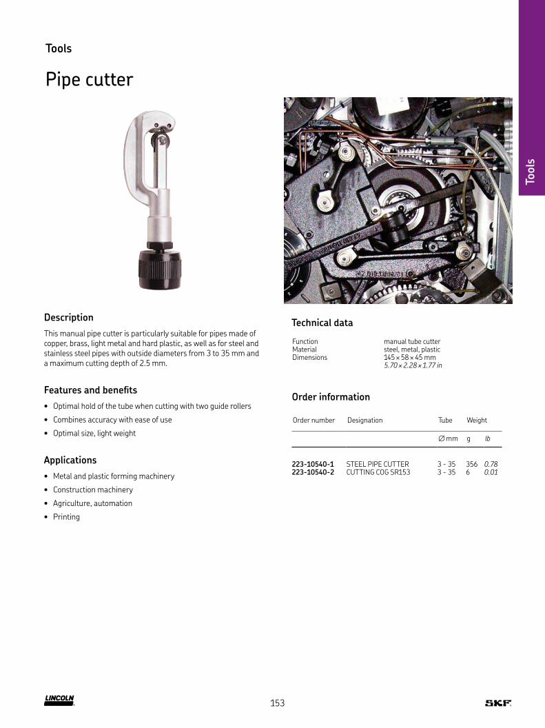
Tools
Tools
Pipe cutter
Description
This manual pipe cutter is particularly suitable for pipes made of copper, brass, light metal and hard plastic, as well as for steel and stainless steel pipes with outside diameters from 3 to 35 mm and a maximum cutting depth of 2 5 mm
Features and benefits
• Optimal hold of the tube when cutting with two guide rollers
• Combines accuracy with ease of use
• Optimal size, light weight
Applications
• Metal and plastic forming machinery
• Construction machinery
• Agriculture, automation
• Printing
Technical data
Function manual tube cutterMaterial steel, metal, plasticDimensions 145 × 58 × 45 mm
5.70 × 2.28 × 1.77 in
Order information
Order number Designation Tube Weight
∅ mm g lb
223-10540-1 STEEL PIPE CUTTER 3 - 35 356 0.78223-10540-2 CUTTING COG SR153 3 - 35 6 0.01
153
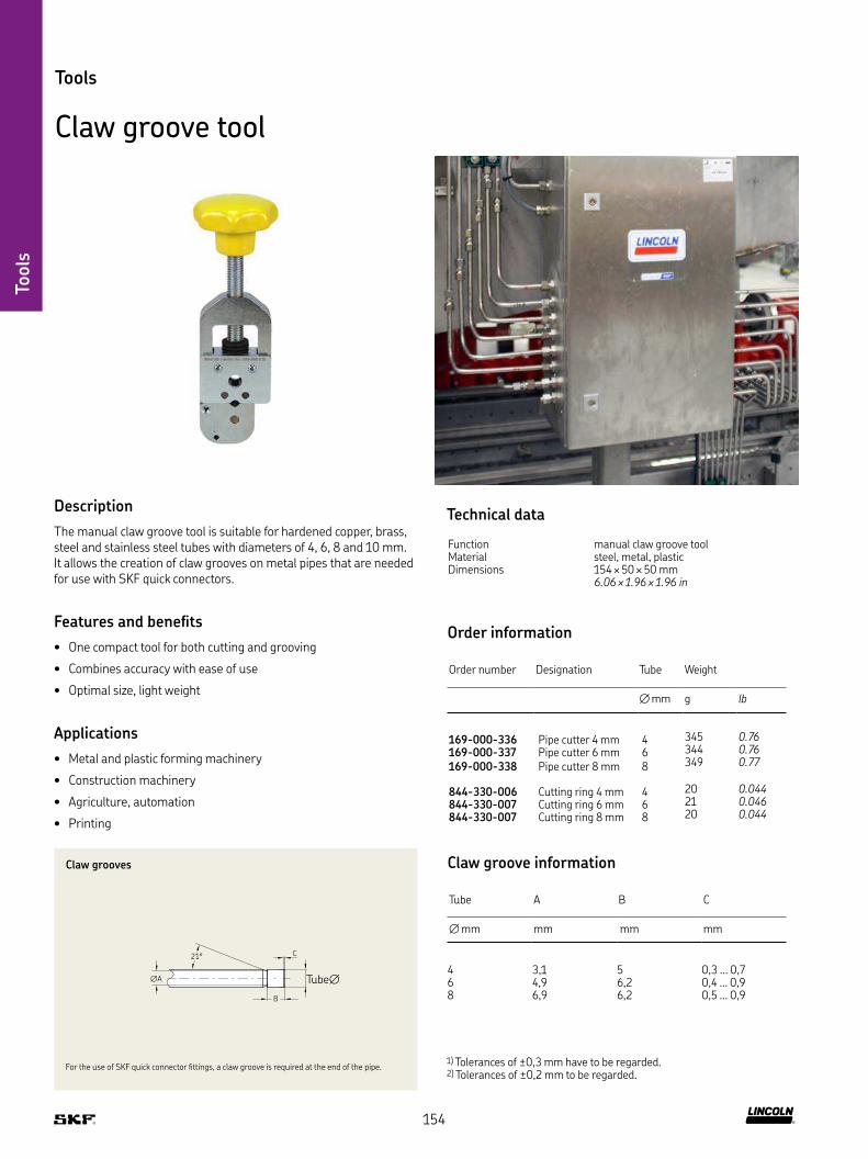
Tools
Tools
Claw groove tool
Description
The manual claw groove tool is suitable for hardened copper, brass, steel and stainless steel tubes with diameters of 4, 6, 8 and 10 mm It allows the creation of claw grooves on metal pipes that are needed for use with SKF quick connectors
Features and benefits
• One compact tool for both cutting and grooving
• Combines accuracy with ease of use
• Optimal size, light weight
Applications
• Metal and plastic forming machinery
• Construction machinery
• Agriculture, automation
• Printing
1) Tolerances of ±0,3 mm have to be regarded 2) Tolerances of ±0,2 mm to be regarded
∅A
C21°
B
Claw grooves
Tube∅
For the use of SKF quick connector fittings, a claw groove is required at the end of the pipe
Claw groove information
Tube A B C
∅ mm mm mm mm
4 3,1 5 0,3 … 0,76 4,9 6,2 0,4 … 0,98 6,9 6,2 0,5 … 0,9
Technical data
Function manual claw groove toolMaterial steel, metal, plasticDimensions 154 × 50 × 50 mm
6.06 × 1.96 × 1.96 in
Order information
Order number Designation Tube Weight
∅ mm g lb
169-000-336 Pipe cutter 4 mm 4 345 0.76
169-000-337 Pipe cutter 6 mm 6 344 0.76
169-000-338 Pipe cutter 8 mm 8 349 0.77
844-330-006 Cutting ring 4 mm 4 20 0.044
844-330-007 Cutting ring 6 mm 6 21 0.046
844-330-007 Cutting ring 8 mm 8 20 0.044
154

Tools
Tools
Tube bender
Description
The easy-to-use manual tube bender is designed for pipe diameters of 6, 8 and 10 mm and has a bending radius range from 1-180° with a visible, marked scale featuring 15° steps The bender is suitable for use with hardened copper, steel and stainless steel tubes
Features and benefits
• Designed for bending hardened copper, steel and stainless steel
• Provides measurements in inches and millimeters
• Combines accuracy with ease of use
• Optimal size, light weight
• Includes oil-absorbing shoe
Applications
• Metal and plastic forming machinery
• Construction machinery
• Textile machinery
• Agriculture
• Automation
• Printing
Technical data
Function manual tube benderMaterial steel, metal, plasticBending radius 1–180°Scale 15° stepsLength 260–370 mm
10.23– 14.56 in
Order information
Order number Designation Tube Weight
∅ mm kg lb
223-13700-8 Tube bender 6 0,7 1.54223-13700-9 Tube bender 8 1,3 2.86223-13700-7 Tube bender 10 1,18 2.60
155
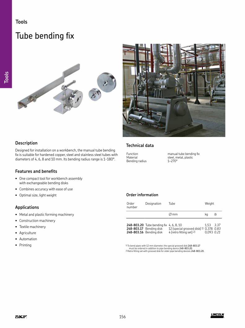
Tools
Tools
Tube bending fix
Description
Designed for installation on a workbench, the manual tube bending fix is suitable for hardened copper, steel and stainless steel tubes with diameters of 4, 6, 8 and 10 mm Its bending radius range is 1-180°
Features and benefits
• One compact tool for workbench assembly with exchangeable bending disks
• Combines accuracy with ease of use
• Optimal size, light weight
Applications
• Metal and plastic forming machinery
• Construction machinery
• Textile machinery
• Agriculture
• Automation
• Printing 1) To bend pipes with 12 mm diameter, the special grooved disk 248-803.17 must be ordered in addition to pipe bending device 248-803.20
2) Retro fitting set with grooved disk for older pipe bending devices 248-803.20
Technical data
Function manual tube bending fixMaterial steel, metal, plasticBending radius 1–270°
Order information
Order number
Designation Tube Weight
∅ mm kg lb
248-803 20 Tube bending fix 4, 6, 8, 10 1,53 3.37248-803 17 Bending disk 12 (special grooved disk) 1) 0,378 0.83248-803 16 Bending disk 4 (retro fitting set) 2) 0,093 0.21
156

Tools
Tools
Hose cutter
Description
This manual hose cutter is particularly suitable for tubes and hoses made of plastic and rubber, including tubes with thin metal layers It cuts tubes with outside diameters up to 12,5 mm
Features and benefits
• Combines accuracy with ease of use
• Highly resistant against stress and flexural vibrations
• Small size, light weight
Applications
• Metal and plastic forming machinery
• Construction machinery
• General industry
• Agriculture
• Printing
Technical data
Function manual hose cutterMaterial steel, metalDimensions 175 × 115 × 10 mm
6.88 × 4.52 × 0.39 in
Order information
Order number Designation Tube
∅ mm
226-12508-5 HOSE CUTTER 1–12,5226-13095-7 HOSE CUTTER REPLACEMENT BLADES 1–12,5
157

Tools
Tools
Grease pump set for pressure and function check
Description
This manual grease pump set for pressure and function check is a perfect tool for lubrication system installation, maintenance or troubleshooting existing systems Its integrated pressure gauge, hose and fitting enable accurate system function check and help to identify system leaks as well as system blockages The set includes two different connection options: a hydraulic coupler for grease nipple, and a fitting for connection of tube ∅6 mm
Features and benefits
• Combines accuracy with ease of use
• Set contains a wide range of fittings
• Robust and reliable tool
• Small size, light weight
Applications
• Metal and plastic forming machinery
• Construction machinery
• General industry
• Agriculture
• Printing
Technical data
Function grease pump set for pressure and function checkConnections hydraulic coupler for grease nipple, or fitting
for connection of tube ∅6 mmMaterial steel, metal
Order information
Order number Designation
604-36879-1 PRESSURE AND FUNCTION TESTING SET
158

Tools
Tools
Drum plug wrench
Description
The drum plug wrench was developed to simplify the opening and
closing of caps and plugs on fluid drums The model 5841 wrench
eliminates the need for cumbersome makeshift tools, such as
screwdrivers and hammers Constructed of safe, non-sparking
cast aluminum, the drum plug wrench features a comfortable,
textured grip This cost-effective wrench is suitable for agriculture,
construction, industrial, fleet maintenance and vehicle service appli-
cations – anywhere that fluid drums are used It is compatible with
standard metal and plastic caps or plugs on 60 l (16 gal) and 200 l
(55 gal) drums
Features and benefits
• Suitable for common cap types – both plastic and metal
• Non-sparking, non-corrosive aluminum construction
• Saves time and effort when loosening and tightening plugs and caps
• Fits large and small caps
• Cost-effective solution
• Simple to use
Applications
• Caps or plugs on 60 l (16 gal) and 200 l (55 gal) drums
Technical data
Function drum plug wrench Application 60 l (16 gal) and 200 l (55 gal) drumsMaterial aluminumWrench 3/4
Order information
Order number Designation
5841 DRUM PLUG WRENCH
159

Tools
Tools
Socket wrench insert for elbows
Description
This socket wrench insert for elbow fitting mounting allows quick
and clean system installation work, especially in machines or in
facilities where lubrication lines have to run around many
corners and barriers
Features and benefits
• Combines accuracy with ease of use
• Highly resistant against stress and flexural vibrations
• Small size, light weight
Applications
• Metal and plastic forming machinery
• Construction machinery
• General industry
• Agriculture
• Printing
Technical data
Function socket wrench insertApplication elbows with max width of 11 mmMaterial tool steelWrench 1/4Dimensions ∅24 mm, height 20 mm
Order information
Order number Designation
917-877 SOCKET WRENCH INSERT FOR ELBOWS
160

Tools
Tools
Mounting stud for hose couplings
Description
The mounting stud is an important tool for the self-assembly of
threaded joints of high-pressure hoses With the aid of the stud, it is
possible to mount the threaded sleeve in the correct position in the
high-pressure hose This is important because incorrectly mounted
sleeves can cause the hose to burst or couplings not to seal
Features and benefits
• Simple mounting without complex measuring with caliper
• Avoids malfunctions in the central lubrication system due to blocked or burst hose lines
• Avoids errors during hose assembly
Applications
• Hose mounting for nominal diameter 6 mm
Technical data
Function mounting studHose type ND 6 mmImmersion depth 11 mmMaterial galvanized steelWeight 20 g; 0.05 lbsDimensions ∅10 mm, ∅6 mm, 40 mm
Order information
Order number Designation
432-23077-1 MOUNTING STUD
161

Refill pumps
Description
Filling pumps make it easier to top up lubricants in reservoirs
of automatic lubrication pumps By using original barrels, hoses and
couplings, it is ensured that no dirt gets into the reservoir during the
filling process Contaminated lubricants that enter the reservoir during
manual filling via the open reservoir lid are the greatest risk of
malfunctions in a centralized lubrication system
Depending on the desired degree of automation, the filling pumps
can be supplied with manual, compressed air or electric drive
For longer transport distances, the use of a filling pump on a trolley
is recommended
Features and benefits
• Improved maintenance of all lubrication systems
• Easy-to-use, application-optimized product design
• Quick and professional refilling with contamination prevention, compared to manual grease refilling
• Optimized consumption of refilling barrel lubricants due to use of perfectly suited barrel follower plates
• Wide range of filling pumps for all common reservoir sizes
Applications
• General mechanic and plant engineering
• Agriculture and forestry industry
• Construction machinery
• Pulp and paper industry
• Renewables industry
• Oil and gas industry
• On-road vehicles
• Heavy industry
• Etc
Refi
ll p
um
ps
162

Refi
ll p
um
ps
Refill pumps
PowerLuber
Description
The Lincoln model 1886 battery-powered grease gun offers the key features you need for tough jobs – nothing more and nothing less The versatility of the two-speed design enables you to address all lubrication points with a single tool, protecting equipment and machinery from costly repair and downtime The tool’s high-ratio gearing will move large quantities of grease quickly when needed, while its low gearing supports deliveries of up to 690 bar
Also, the tool has a convenient, built-in LED to illuminate the work area and a three-point stance to keep the tool upright
Features and benefits
• Flex hose that comes with anti-kink spring guards on each end and is the ideal size for most lubrication tasks
• Integrated vent valve purges trapped air to help assure easy prime
• The filler nipple facilitates a quick, clean refill for those who prefer to bulk fill their barrel
• Lithium-ion technology is powerful and efficient, delivering an even flow of energy
• Display shows battery charge and grease output in both grams and ounces
Applications
• General mechanic and plant engineering
• Agriculture, construction, automotive, trucking
• Heavy equipment
• Wind energy
• General industry
Technical data
Function battery-operated grease gunOperating power 20 VOperating pressure max 690 bar; 10 000 psiDelivery rate max 284 g/min; 10 oz/minReservoir capacity 411 g; 14.5 ozOperating temperature –18 to 50 °C; 0 to 122 °FRated current 5 0 ALubricant grease up to NLGI 2Material steel, metal, plastic
Order information
Order number Designation Approval Weight
kg lb
1886 Single battery unit with charger UL 3,4 7.51886-E Single battery unit with charger CE 3,4 7.5
1871 20V Li-ion battery, 2,5 Ah UL, CE – –1872 20V Li-ion battery, 4,0 Ah UL, CE – –
163

Refi
ll p
um
ps
Refill pumps
Manual grease filler guns
Description
The manual cartridge grease gun is ideal for agricultural, industrial and construction industries and for private use It can be utilized to lubricate directly or as filler pump for automatic lubrication systems The tool is designed for rough treatment on the job with a cast iron pump head, precision fit plunger and extra heavy follower spring
Features and benefits
• For use with cartridges and bulk grease
• Knurled body for firm and safe grip
• High-output setting delivers twice the grease per stroke
• High or low pressure for light- or heavy-duty greasing action
• Extension swivels 360° for hard-to-reach fittings
• Plated barrel, head and handle
Applications
• General mechanic and plant engineering
• Agriculture, construction, automotive, trucking
• Heavy equipment
• Wind energy
• General industry
Technical data
Function manually operated cartridge grease gunDelivery rate max 284 g/min; 10 oz/minCartridge capacity 420 ml; 14.2 fl ozOperating temperature –18 to 50 °C; 0 to 122 °FLubricant grease up to NLGI 2Material steel, metal, plastic
Order information
Order number Designation Operation pressure max
Weight
bar psi kg lb
001013 LEVER GUN 275 4 000 2,09 4.61
001142 LEVER GUN 400 5 800 1,85 4.08
001133 PISTOL GUN 414 6 000 1,62 3.57
164

Refi
ll p
um
ps
Refill pumps
Filler cylinder
Description
Lubricant outlets of automatic lubrication system pumps can, as an option, be equipped with one suitable filler socket in order to fill the unit using a filling cylinder (cartridge) A filler cylinder is only recommended for systems with low lubricant consumption and reservoir sizes up to 2 kg
Features and benefits
• Robust and sustainable manual filler pump
• Knurled body for firm and safe grip
• Easy to use
Applications
• General mechanic and plant engineering
• Agriculture, construction, automotive, trucking
• General industry
• Heavy equipment
• Wind energy
Technical data
Function manually operated cartridge filler cylinder
Reservoir capacity 420 ml; 14.2 fl ozOperating temperature –18 to 50 °C; 0 to 122 °FLubricant grease up to NLGI 2Material steel, metal, plastic
Order information
Order number Designation Thread
mm
169-000-171 Filler cylinder –
169-000-174 Filler coupling M20x1,5
5590-00000002 Filler coupling M22x1,5
165

Refi
ll p
um
ps
Refill pumps
Manually and pneumatically operated filling pumps 169
Description
The 169 series of filling pumps is available in manual or pneumatic models that are suitable for barrel sizes of 15, 20, 25 and 50 kg The pumps are offered in stationary or mobile versions
Features and benefits
• Easy and cost-efficient filling of pump reservoirs
• No contamination of the lubricant during the filling process
• Steel pump with guided grease follower piston
• Centering cover that positions the pump centrally in the barrel and ensures optimum residual emptying
Applications
• Construction machinery
• Agriculture vehicles
• Production plants
Technical data
Function filling pump
Design manually operated filling pumpDelivery rate max 100 g/stroke; 10 oz/stroke
Design pneumatically operated filling pumpDelivery rate max 1 800 g/min; 3.97 lbs/minRatio 1 : 3Operating pressure max 24 bar; max. 348 psiAir pressure max 8 bar; max max. 116 psi
Barrel capacities 15 20, 25 and 50 kgOperating temperature -10 to +40 °C; 14 to 104 °FLubricant fluid grease and grease up to NLGI 2Coupling acc to ISO 241 B DN6 R 1/4Hose length 2 m; 6.5 ftMaterial steel, metal, plasticDimensions max 550 x 550 x 950
max. 21.65 x 21.65 x 37.4
Order number Designation Drum Inner diameter Medium Delivery rate per stroke
Dimensions D x H Weight
kg mm in cm3 in3 mm mm kg lb
169-000-004 MANUAL FILLING PUMP 15L,STATIONARY 15 267 10.5 NLGI 1/2 4 0.25 360×640 14,2×25,2 4,383 9.66169-000-012 MANUAL FILLING PUMP 10L,STATIONARY 10 236 9.3 NLGI 1/2 25 1.53 280×610 11×24 4,68 10.32169-000-016 MANUAL FILLING PUMP 20L,STATIONARY 20 290 11.4 NLGI 1/2 25 1.53 300×590 11,8×23,2 5,12 11.30169-000-082 MANUAL FILLING PUMP 25/50L,MOBILE 25 / 50 350 1) 13.8 1) 00/000 100 6.1 350×800 23,2×31,5 7 15.43169-000-084 MANUAL FILLING PUMP 25L,STATIONARY 25 350 1) 13.8 1) 00/000 250 15.3 320×630 12,6×24,8 4 8.82169-000-042 MANUAL FILLING PUMP 25L,MOBILE 25 300-335 11.2-13.2 NLGI 1/2 45 2.7 550×780 21,7×30,7 16,8 37.04169-000-054 MANUAL FILLING PUMP 50L,MOBILE 50 355-387 14-15.2 NLGI 1/2 45 2.7 550×950 21,7×37,4 10 22.05169-000-342 MANUAL FILLING PUMP 25L,STATIONARY 25 300-335 11.2-13.2 NLGI 1/2 45 2.7 340×700 13,4×27,6 6,38 14.06
1) max outer diameter
166

Refi
ll p
um
ps
Refill pumps
Electrically operated filling pump EFFP
Description
The EFFP electric grease filling pump is a piston pump for grease drum sizes from 16 to 25 kg The delivery stroke is generated at the lower end of the intake tube by a delivery piston that is controlled by an electrically driven eccentric shaft The pump is activated using an ON/OFF switch attached to the terminal box
Features and benefits
• Suitable for pressures up to 250 bar
• Suitable for oil, fluid grease and grease
• Integrated automatic shut-off function for use with grease guns
Applications
• Wind energy
• Stationary and mobile vehicles
Technical data
Function electrically operated piston pumpDelivery rate max 400 cm3/min; 24 in3/minBarrel capacities 16 and 25 kgOperating temperature –10 to +60 °C; 14 to 140 °FLubricant oil, fluid grease and grease up to
NLGI 2Outlet fitting G 1/4Automatic shut-off, fixed 250 barPressure regulating valve, fixed 300 barRestart after pressure relief < 150 bar
Material steel, metal, plasticSystem voltage 230 V AC/50 to 60 HzMotor power 370 WProtection class IP54Insulation class FIntake current 2,73 AElectrical connection grounded plug, 3 m cable -
motor protection via circuitbreaker
Dimensions (pump only) 550 x 900 mm; 21.7 x 35.4 in
Order information
Order number Designation Weight
kg lb
24-1560-3577 El barrel pump EFFP 34,5 76.0724-1560-3578 El barrel pump EFFP
with signal input34,9 76.95
24-1868-4334 High-pressure hose, max 275 bar, 5 m
– –
412-423W Screw union G1/4 412-423W – –995-001-500 Coupling socket G1/4 – –995-000-705 Coupler plug G1/4 – –169-000-031 Grease gun – –
Accessories for EFFP
Order number Designation Suitable drum sizes
Weight
kg kg lb
24-1722-2545 Carrying frame 16 / 25 13,2 29.1124-1722-2551 Carrying frame with handle
and wheels16 / 25 16,6 36.60
24-1722-2552 Carrying frame with wheels 16 / 25 15 33.0824-1952-2034 Follower plate ∅ 265-285 16 / 25 0,7 1.5424-1952-2035 Follower plate ∅ 285-305 16 / 25 1 2.2124-1952-2036 Follower plate ∅ 305-350 16 / 25 1,5 3.31
167

226-12490-3 898-610-000226-12557-1 941-206-108226-12557-2 941-209-104226-12557-3 941-212-101226-12557-4 941-215-104226-12557-6 941-220-104226-12557-7 941-210-104226-13095-1 898-710-001226-13095-6 179-990-186401-013-111 222-12599-9401-016-132 222-12521-2401-016-171 222-13678-1401-016-191 222-12578-5401-021-111 222-13678-4404-301 223-14083-3404-302 223-13032-1404-403 223-13069-1404-403W 223-12270-8404-404 223-12531-8404-405W 223-13021-4404-406-S3 223-13615-5404-413 223-12271-8404-425 223-13069-2406-301 223-12295-3406-302 223-12373-9406-302-S3 223-14082-5406-303 223-14234-7406-323 223-13766-9406-331 223-12295-2406-332 223-12374-9406-332-S3 223-13638-2406-333 223-14129-1406-403 223-10263-8406-403-S3 223-14184-5406-403W 223-13016-3406-403W-S3 223-13658-2406-404 223-12483-2406-405 223-12485-8406-405W 223-13048-1406-406 223-12482-9406-407 223-12484-2406-409 223-13050-4406-411 223-12481-4406-413 223-14129-4406-413W 223-12477-1406-413W-S3 223-13614-7406-415W 223-12380-6406-416 223-12368-4406-423 223-12271-7406-423-S3 223-13658-5406-423W 223-12270-7406-423W-S3 223-13614-9406-425 223-13021-3406-433 223-13023-1406-433-S3 223-13658-6406-435 223-13023-3406-435-S3 223-13677-2406-443 223-12533-9406-443-S3 223-13658-7406-445 223-13023-2406-445-S3 223-13677-4406-446 223-14181-3406-463W 223-13766-6408-301 223-12295-6408-302 223-13032-4408-403 223-12361-6408-403W 223-12477-6408-405 223-12362-8408-405W 223-14240-5408-407 223-12484-6408-408 223-12531-9408-408-S3 223-13615-3408-409 223-12409-6408-411 223-12481-6408-413W 223-10080-3
Cross reference list
Historical order number SKF Lincoln order number Historical order number SKF Lincoln order number
408-416 223-12368-6408-423W 223-12270-9408-423W-S3 223-13614-9408-425 223-12362-4410-301 223-12295-8410-302 223-13032-6410-323 223-14304-2410-403 223-14129-4410-403W 223-12272-9410-403W-S3 223-14420-7410-404 223-12483-8410-405W 223-13048-5410-407 223-13057-5410-409 223-12409-9410-410 223-12531-2410-410-S3 223-13615-6410-411 223-13028-2410-413W 223-14214-4410-416 223-12368-8410-425 223-12485-2410-433W 223-10313-7410-443-S3 223-14420-4410-463 223-10313-2412-301 223-12296-1412-302 223-12373-2412-403W 223-12360-8412-404 223-12280-9412-411 223-12481-8412-412 223-13732-8412-416 223-13698-4412-423W 223-12477-9415-301 223-12296-9415-302 223-12374-8415-403W 223-12361-9415-405W 223-13021-7415-407 223-12563-2415-409 223-12409-8415-415 223-12531-6415-415-S3 223-12454-8415-416 223-12564-2415-433W 223-13621-8418-301 223-12583-1418-302 223-12374-7418-403W 223-13766-1418-403W-S3 223-14420-8418-416 223-12564-8418-418 223-13732-4422-407 223-13057-4428-403W 223-13610-9428-413W 223-14214-9441-008-511 223-13021-1441-008-511-S3 223-13715-1441-110-163 223-13028-4441-112-162 223-12286-8443-190-901 223-13050-3443-215-001 223-12562-2443-306-341 223-14171-1443-308-351 223-14102-3443-406-061 223-14190-6443-408-081 223-14190-7443-410-101 223-13040-9443-412-121 223-13761-5443-415-151 223-14190-5445-516-081 223-12284-7445-516-101 223-12369-9445-519-041 223-13629-1445-519-061 223-12479-5445-521-122 223-13669-3445-529-041 223-12480-2445-531-061 223-12369-7445-531-062 223-12480-7445-808-351 223-13040-1445-810-371 223-14189-1460-706-001 223-10297-5460-710-001 223-10297-6
168

Cross reference list
Historical order number SKF Lincoln order number Historical order number SKF Lincoln order number
460-712-001 223-10297-9466-411-001 223-10530-4466-413-001 223-13702-7466-416-001 223-13702-1466-418-001 223-13702-6471-106-163 223-13655-1471-110-163 223-13655-7471-112-163 223-14268-4504-410 223-12542-2506-410 223-13705-5506-412 223-13622-3506-413 223-10986-1508-410 223-13024-4508-412 223-13622-7508-413 223-13024-8510-412 223-12542-7512-410 223-12452-8650-050 213-12505-1650-060 213-12168-8650-080 213-12505-3650-100 213-12505-2650-120 213-12505-5650-200 213-12505-896-0203-0058 223-10814-296-0204-0058 223-12477-896-0222-0058 223-13016-296-0223-0058 223-13749-396-0308-0060 223-10889-296-0319-0058 223-11242-596-0328-0058 223-14214-896-0408-0058 223-12483-596-0506-0060 223-10307-296-0510-0060 223-13033-296-0518-0060 223-13693-996-0706-0060 223-13693-496-0708-0060 223-13693-696-0710-0060 223-13693-296-0711-0060 223-13693-196-0722-0060 223-12273-296-1108-0058 223-12477-296-1109-0058 223-13016-696-1110-0058 223-13016-496-1111-0058 223-13016-996-1112-0058 223-13016-796-1113-0058 223-14129-396-1116-0058 223-13621-196-1117-0058 223-13749-596-1120-0058 223-12359-696-1121-0058 223-12360-696-1214-0058 223-11242-496-1508-0060 223-10670-396-1511-0060 223-12582-596-1523-0060 223-14293-296-1532-0060 223-14152-296-1533-0060 223-14293-496-1545-0060 223-14293-896-1555-0060 223-12581-996-1610-0060 223-10688-196-1611-0060 223-10187-196-1612-0060 223-13054-496-1622-0060 223-12287-896-1623-0060 223-12288-296-1643-0060 223-14293-196-1651-0060 223-12577-896-1653-0060 223-12577-296-1654-0060 223-12580-296-1656-0060 223-13759-796-3101-0058 222-13678-296-3102-0058 222-12599-296-3105-0058 222-12578-996-3106-0060 223-14189-696-3109-0058 222-13678-896-3110-0058 222-12521-896-3111-0058 222-11053-196-3112-0060 223-13785-8
96-3113-0058 222-13678-396-3115-0060 223-14189-796-3116-0058 222-12521-596-3117-0058 222-12521-696-3118-0058 222-12521-496-3120-0058 222-12578-496-3121-0058 222-12578-896-3122-0058 222-12578-396-3123-0058 222-12047-296-3125-0058 222-12599-396-3126-0058 222-12578-296-3127-0058 222-12047-896-3128-0058 222-12047-496-3131-0058 222-12599-596-3132-0058 222-13670-196-3134-0058 222-12599-696-3208-0060 223-10374-396-3210-0060 223-14189-596-3212-0060 223-14189-996-3216-0060 223-14189-296-3220-0060 223-14189-396-5608-0058 223-13032-396-5610-0058 223-12374-696-5708-0058 223-12295-596-5710-0058 223-12295-996-5909-0058 223-13621-696-6002-0058 223-12533-596-6202-0058 223-12533-696-6904-0058 223-12563-596-7004-0058 223-13629-196-7006-0058 223-12479-996-7008-0058 223-12479-896-7104-0158 223-12480-896-7906-0058 223-12285-896-7908-0058 223-12285-996-7910-0058 223-12285-596-7912-0058 223-12285-696-7920-0058 223-12285-796-8010-0058 223-13669-496-8910-0058 223-13655-296-8912-0058 223-13655-499-0204-0058 223-13658-999-0215-0058 223-13715-999-0217-0058 223-13715-699-0228-0058 223-14184-299-2712-0058 223-13639-999-5604-0058 223-13638-699-5612-0058 223-14082-399-5704-0058 223-13639-5DIN7513-BM5x10 206-12124-3DIN7513-BM6x16 206-12125-4DIN912-M4x12-A4 201-13741-1DIN912-M4x20-8 8 201-12015-5DIN912-M5x10-A2 201-13608-6DIN912-M6x16-8 8 201-12019-9DIN912-M6x25-8 8 201-12018-7DIN912-M6x60-8 8 201-12019-6DIN912-M8x16-8 8 201-12021-3DIN933-M10x40-8 8 200-12523-3DIN933-M5x12-8 8 200-13092-1DIN933-M6x16-8 8 200-13022-4DIN933-M6x20-8 8 200-13022-7DIN933-M6x25-8 8 200-13022-1DIN933-M8x20-8 8 200-12553-4DIN933-M8x25-8 8 200-10406-7DIN934-M5-8 207-12138-2DIN934-M6-8 207-12135-5DIN936-M14x1 5-5 207-12141-1DIN936-M16x1 5-5 207-12141-8DIN985-M12-6 207-12516-6DIN985-M3-6 207-12516-9DIN985-M8-6 207-12516-1
169

Index
24-1560-3577 167
24-1560-3578 167
24-1722-2545 167
24-1722-2551 167
24-1722-2552 167
24-1868-4334 167
24-1952-2034 167
24-1952-2035 167
24-1952-2036 167
44-1755-2019 25
44-1755-2029 75
96-0335-0058 43
96-0342-0058 43
96-0508-0060 53
96-0512-0060 53
96-0606-0060 53
96-0608-0060 53
96-0712-0060 53
96-0715-0060 53
96-0718-0060 53
96-0806-0058 62
96-0808-0058 62
96-0810-0058 62
96-0818-0058 62
96-0906-0058 62
96-1114-0058 44
96-1206-0058 43
96-1214-0058 43
96-1406-0060 59
96-1408-0060 59
96-1410-0060 59
96-1412-0058 51
96-1541-0060 59
96-1542-0060 59
96-1543-0060 59
96-1551-0060 59
96-1556-0060 59
96-1633-0060 59
96-1642-0060 59
96-1644-0060 59
96-1652-0060 59
96-1706-0058 62
96-1806-0058 62
96-1808-0058 62
96-2106-0058 52
96-2118-0058 52
96-2122-0058 52
96-3102-0058 78
96-3106-0058 78
96-3112-0058 78
96-3118-0060 63
96-3122-0060 63
96-3129-0058 78
96-3133-0058 78
96-3136-0058 78
96-3137-0058 78
96-5911-0058 44
96-5912-0058 44
96-5913-0058 44
96-6112-0058 51
96-6304-0058 62
96-6306-0058 62
96-6308-0058 62
96-6404-0058 62
96-6406-0058 62
96-6408-0058 62
96-7108-0058 57
96-7808-0058 57
96-7812-0058 57
96-7815-0058 57
96-7818-0058 57
96-7822-0058 57
96-7914-0058 58
96-7916-0058 58
96-8006-0058 57
96-8008-0058 57
96-8012-0058 57
96-8014-0058 57
96-8016-0058 57
96-8804-0058 60
96-8906-0058 60
99-0222-0058 45
105-35025-5 104
105-35134-1 104
105-35134-3 104
105-35134-4 104
105-35134-9 104
105-35183-3 104
105-35251-1 104
105-35251-3 104
105-35308-1 104
106-35203-1 105
106-35203-2 105
106-35203-3 105
106-35203-4 105
106-35203-7 105
106-35231-1 105
106-35231-2 105
106-35231-3 105
106-35231-6 105
106-35267-4 105
106-35292-1 105
106-35292-2 105
111-35114-1 114
111-35301-4 114
111-35306-5 103
112-35127-2 102
112-35127-5 102
112-35127-7 102
112-35225-4 102
113-35075-2 103
113-35075-3 103
161-110-031+924 133
161-120-064+924 133
161-212-054 130
161-600-036 132
162-310-005 141
169-000-004 166
169-000-012 166
169-000-016 166
169-000-031 167
169-000-042 166
169-000-054 166
169-000-082 166
169-000-084 166
169-000-171 165
169-000-174 165
169-000-336 154
169-000-337 154
169-000-338 154
169-000-342 166
169-101-004 135
169-101-607 136
169-102-015 136
169-102-020 135
169-102-506 135
169-104-008 135
169-104-015 136
169-104-020 135
169-106-004 135
169-106-011 136
169-106-015 136
169-106-020 135
169-110-010 136
169-110-015 136
169-110-020 135
169-116-000 135
169-125-015 136
169-125-020 135
169-140-001 136
169-200-008 34
179-990-186 121
200-10406-7 121
200-12007-6 121
200-12009-7 121
200-12399-2 121
200-12523-3 121
200-12553-4 121
200-12553-8 121
200-13017-5 121
200-13017-9 121
200-13022-1 121
200-13022-4 121
200-13022-7 121
Index
170

IndexIndex
200-13037-3 121
200-13092-1 121
201-12015-5 121
201-12018-7 121
201-12019-6 121
201-12019-9 121
201-12021-3 121
202-085-S 131
202-175-30 127
202-275-2 127
206-12124-3 121
206-12125-4 121
207-168-2 123
207-168 U2 123
207-168 U7 123
207-188-2 123
207-188 U11 123
210-042 33
213-870 147
213-870F* 147
213-870 U1 147
213-870 U2 147
213-870 U2 147
213-880 147
213-880 U1 147
213-930F 147
220-12238-3 149
222-10365-3 78
222-11053-1 78
222-12047-2 78
222-12047-4 78
222-12047-8 78
222-12521-2 78
222-12521-4 78
222-12521-5 78
222-12521-6 78
222-12521-8 78
222-12578-2 78
222-12578-3 78
222-12578-4 78
222-12578-5 78
222-12578-8 78
222-12578-9 78
222-12599-2 78
222-12599-3 78
222-12599-5 78
222-12599-6 78
222-12599-9 78
222-13618-1 78
222-13618-2 78
222-13618-3 78
222-13618-5 78
222-13670-1 78
222-13678-1 78
222-13678-2 78
222-13678-3 78
222-13678-4 78
222-13678-8 78
222-14180-3 78
222-14180-5 78
222-14180-6 78
222-14180-7 78
222-14180-9 78
223-10055-9 46
223-10080-3 44
223-10187-1 59
223-10263-8 43
223-10297-1 71
223-10297-5 71
223-10297-6 71
223-10297-7 71
223-10297-9 71
223-10307-2 53
223-10313-2 43
223-10313-7 44
223-10364-3 56
223-10364-6 56
223-10374-3 63
223-10389-3 57
223-10389-4 58
223-10530-4 79
223-10540-1 153
223-10540-2 153
223-10550-1 48
223-10550-2 48
223-10550-6 48
223-10550-8 48
223-10563-5 48
223-10563-6 48
223-10563-7 48
223-10563-8 48
223-10638-3 65
223-10670-3 59
223-10688-1 59
223-10814-2 44
223-10889-2 60
223-10986-1 47
223-11089-3 46
223-11185-1 54
223-11229-9 46
223-11242-4 43
223-11242-5 43
223-12270-7 44
223-12270-8 44
223-12270-9 44
223-12271-7 43
223-12271-8 43
223-12272-9 44
223-12272-9 128
223-12273-2 53
223-12273-5 44
223-12280-9 50
223-12284-7 58
223-12285-5 58
223-12285-6 58
223-12285-7 58
223-12285-8 58
223-12285-9 58
223-12286-8 60
223-12287-8 59
223-12288-2 59
223-12290-2 54
223-12290-7 54
223-12291-2 54
223-12291-4 54
223-12291-6 54
223-12292-2 55
223-12292-5 55
223-12292-9 55
223-12295-2 41
223-12295-3 41
223-12295-5 41
223-12295-6 41
223-12295-8 41
223-12295-9 41
223-12296-1 41
223-12296-3 41
223-12296-5 41
223-12296-8 41
223-12296-9 41
223-12359-6 44
223-12360-6 44
223-12360-8 44
223-12361-6 43
223-12361-9 44
223-12362-4 50
223-12362-8 50
223-12363-2 46
223-12363-6 46
223-12364-4 47
223-12364-6 56
223-12365-2 50
223-12366-2 49
223-12366-6 49
223-12367-2 49
223-12367-4 49
223-12368-2 56
223-12368-4 56
223-12368-6 56
223-12368-8 56
223-12369-7 57
223-12369-9 58
223-12372-9 54
223-12373-2 42
171
Index
223-12373-6 42
223-12373-9 42
223-12374-2 42
223-12374-6 42
223-12374-7 42
223-12374-8 42
223-12374-9 42
223-12377-7 45
223-12377-8 45
223-12380-6 51
223-12409-2 56
223-12409-6 56
223-12409-8 56
223-12409-9 56
223-12423-7 52
223-12429-1 54
223-12432-2 52
223-12432-8 52
223-12452-5 45
223-12452-7 45
223-12452-8 47
223-12452-9 45
223-12453-1 51
223-12454-1 46
223-12454-3 46
223-12454-5 46
223-12454-6 46
223-12454-8 46
223-12455-1 49
223-12455-2 49
223-12455-5 49
223-12456-1 58
223-12456-6 57
223-12456-7 58
223-12456-8 57
223-12456-9 58
223-12477-1 44
223-12477-2 44
223-12477-6 44
223-12477-6 128
223-12477-8 44
223-12477-9 44
223-12479-5 58
223-12479-8 58
223-12479-9 58
223-12480-2 57
223-12480-7 57
223-12481-4 60
223-12481-6 60
223-12481-8 60
223-12482-9 46
223-12483-2 50
223-12483-5 50
223-12483-8 50
223-12484-2 49
223-12484-6 49
223-12485-2 50
223-12485-8 50
223-12531-2 46
223-12531-4 46
223-12531-6 46
223-12531-8 46
223-12531-9 46
223-12533-5 43
223-12533-9 43
223-12535-5 54
223-12535-9 54
223-12541-5 49
223-12542-2 47
223-12542-7 47
223-12562-2 50
223-12562-7 50
223-12562-8 50
223-12563-2 49
223-12563-5 49
223-12563-9 49
223-12564-2 56
223-12564-3 56
223-12564-8 56
223-12567-1 80
223-12573-6 49
223-12577-2 59
223-12577-8 59
223-12580-2 59
223-12581-9 59
223-12582-5 59
223-12583-1 41
223-13016-2 44
223-13016-3 44
223-13016-4 44
223-13016-6 44
223-13016-7 44
223-13016-9 44
223-13021-1 43
223-13021-3 50
223-13021-4 51
223-13021-6 51
223-13021-7 51
223-13023-1 43
223-13023-3 50
223-13024-1 47
223-13024-4 47
223-13024-8 47
223-13025-6 49
223-13028-2 60
223-13028-4 60
223-13032-1 42
223-13032-3 42
223-13032-4 42
223-13032-6 42
223-13032-9 42
223-13033-2 53
223-13040-1 63
223-13040-3 61
223-13040-7 61
223-13040-9 61
223-13048-1 51
223-13048-5 51
223-13048-6 51
223-13048-8 51
223-13049-3 46
223-13050-2 56
223-13050-3 56
223-13050-4 56
223-13051-1 54
223-13051-2 54
223-13052-8 54
223-13054-4 59
223-13057-2 49
223-13057-4 49
223-13057-5 49
223-13069-1 43
223-13079-1 54
223-13096-2 44
223-13610-8 46
223-13610-9 44
223-13614-6 45
223-13614-7 45
223-13614-9 45
223-13615-3 46
223-13615-5 46
223-13615-6 46
223-13616-3 49
223-13619-2 47
223-13619-9 47
223-13620-8 51
223-13621-1 44
223-13621-6 44
223-13621-8 44
223-13622-1 47
223-13622-3 47
223-13622-7 47
223-13629-1 58
223-13638-1 42
223-13638-2 42
223-13638-3 42
223-13638-6 42
223-13638-7 42
223-13638-9 42
223-13639-1 41
223-13639-2 41
223-13639-3 41
223-13639-4 41
223-13639-5 41
172
Index
223-13639-7 41
223-13639-8 41
223-13639-9 41
223-13640-1 65
223-13640-2 65
223-13640-3 65
223-13640-4 65
223-13640-5 65
223-13640-8 65
223-13640-9 65
223-13643-1 55
223-13643-2 55
223-13643-3 55
223-13643-4 55
223-13643-6 55
223-13643-8 55
223-13655-1 60
223-13655-2 60
223-13655-4 60
223-13655-5 60
223-13655-7 60
223-13655-7 64
223-13655-8 64
223-13655-9 64
223-13658-2 45
223-13658-4 45
223-13658-5 43
223-13658-6 43
223-13658-7 43
223-13658-9 45
223-13669-3 58
223-13669-4 57
223-13671-2 56
223-13671-9 56
223-13672-3 49
223-13672-8 49
223-13673-4 118
223-13675-2 50
223-13675-6 50
223-13677-2 50
223-13677-5 51
223-13679-3 58
223-13679-8 58
223-13679-9 58
223-13681-1 54
223-13684-2 54
223-13685-1 60
223-13685-3 60
223-13686-1 48
223-13692-3 55
223-13693-1 53
223-13693-2 53
223-13693-4 53
223-13693-6 53
223-13693-9 53
223-13694-1 64
223-13694-3 64
223-13694-6 64
223-13694-7 64
223-13698-4 56
223-13700-7 155
223-13700-8 155
223-13700-9 155
223-13702-1 79
223-13702-5 79
223-13702-6 79
223-13702-7 79
223-13702-9 79
223-13705-5 47
223-13706-3 55
223-13715-1 43
223-13715-6 45
223-13715-9 45
223-13732-4 46
223-13732-8 46
223-13749-3 44
223-13749-5 44
223-13758-4 56
223-13759-7 59
223-13761-5 61
223-13761-7 61
223-13766-1 44
223-13766-6 44
223-13766-9 46
223-13770-2 55
223-13770-5 55
223-13770-6 55
223-13770-8 55
223-13785-8 63
223-13791-5 47
223-14082-3 42
223-14082-5 42
223-14082-6 42
223-14083-3 41
223-14089-5 58
223-14089-6 58
223-14089-9 57
223-14092-5 41
223-14102-3 63
223-14116-2 53
223-14116-9 53
223-14129-1 46
223-14129-2 46
223-14129-3 44
223-14129-4 43
223-14130-2 48
223-14130-2 48
223-14130-7 48
223-14130-9 48
223-14152-2 59
223-14171-1 63
223-14171-4 63
223-14171-5 63
223-14171-8 63
223-14184-2 45
223-14184-5 43
223-14187-4 48
223-14187-4 48
223-14189-1 63
223-14189-2 63
223-14189-3 63
223-14189-5 63
223-14189-6 63
223-14189-7 63
223-14189-9 63
223-14190-1 61
223-14190-2 61
223-14190-4 61
223-14190-5 61
223-14190-6 61
223-14190-7 61
223-14214-2 44
223-14214-4 44
223-14214-5 44
223-14214-8 43
223-14214-9 44
223-14215-2 65
223-14215-3 65
223-14215-4 65
223-14215-5 65
223-14234-4 46
223-14234-7 46
223-14238-4 58
223-14240-5 51
223-14241-2 71
223-14241-5 71
223-14241-9 71
223-14244-6 61
223-14244-8 61
223-14253-1 48
223-14253-2 48
223-14253-3 48
223-14253-4 48
223-14253-5 48
223-14268-4 60
223-14268-7 60
223-14293-1 59
223-14293-2 59
223-14293-4 59
223-14293-8 59
223-14304-2 46
223-14304-5 46
223-14304-7 46
223-14418-7 46
173
Index
223-14420-7 45
223-14420-8 45
223-14424-5 50
223-14464-1 55
223-14464-9 54
223-14464-9 54
223-14497-1 48
223-14497-3 48
223-14497-4 48
223-14497-8 48
225-12324-3 112
225-12324-5 112
225-12324-8 112
225-12325-1 112
225-12325-2 112
225-12414-6 112
225-12414-7 112
225-12414-8 112
225-12486-5 112
225-12576-1 112
225-12576-2 112
225-12576-3 112
225-13039-2 112
225-13039-8 112
226-10159-1 89
226-10159-9 89
226-10205-5 85
226-10214-4 90
226-10214-7 90
226-10223-2 88
226-10223-4 88
226-10223-6 88
226-10622-8 86
226-11313-8 87
226-11313-9 87
226-11315-1 87
226-11315-2 87
226-12335-7 117
226-12337-1 117
226-12337-2 118
226-12337-3 118
226-12337-4 118
226-12337-5 118
226-12337-6 118
226-12338-1 117
226-12338-2 118
226-12338-3 118
226-12338-4 118
226-12338-5 118
226-12338-6 118
226-12343-1 120
226-12343-2 120
226-12343-5 120
226-12508-5 157
226-13058-3 120
226-13058-5 120
226-13095-7 157
226-13097-3 120
226-13673-1 117
226-13673-5 118
226-13717-1 117
226-13717-2 118
226-13717-3 118
226-13717-4 118
226-13718-1 118
226-13753-9 87
226-13756-9 86
226-13773-4 91
226-14097-4 90
226-14097-5 89
226-14111-1 85
226-14111-2 86
226-14111-3 86
226-14111-4 86
226-14123-2 87
226-14123-3 87
226-14123-4 87
226-14123-5 87
226-14139-1 85
226-14157-1 86
226-14157-2 86
226-14157-3 86
226-14157-4 88
226-14157-5 88
233-13651-1 151
233-13651-6 151
233-14419-1 151
234-10396-2 137
234-10396-9 137
234-10898-4 137
234-13101-2 137
234-13101-4 137
234-13132-7 137
234-13132-8 137
234-13136-2 137
234-13156-6 137
234-13182-7 137
234-13182-8 137
235-13108-4 132
235-13114-1 132
243-001 10 75
243-001 20 75
248-602 20 135
248-602 25 135
248-610 01 75
248-803 16 156
248-803 17 156
248-803 20 156
251-10309-1 143
251-10309-2 143
251-10780-2 143
251-14040-1 143
251-14040-2 143
251-14040-3 143
251-14040-4 143
251-14040-5 143
251-14044-8 143
251-14045-1 143
251-14045-8 143
251-14063-1 143
251-14063-4 143
251-14063-9 143
251-14073-9 143
251-14109-2 143
251-14109-3 143
267-001 03 75
267-001 13 18
267-001 17 18
267-001 19 18
267-001 36 75
267-001 47 75
267-001 60 75
301-001 18
301-001DK 24
301-005 18
301-005-S3 18
301-020 18
301-020 127
301-020 128
301-020-S3 18
301-034 76
301-134 76
303-17546-1 149
304-16337-1 76
304-19167-1 76
304-19230-1 76
304-19437-1 76
304-19509-1 76
304-19548-1 76
304-19787-1 76
321-581 99
322-581 99
322-861 99
323-581 99
324-581 99
324-861 99
325-581 99
326-581 99
326-663 99
328-581 99
328-861 99
330-581 99
330-861 99
332-861 99
174

Index
334-861 99
336-861 99
338-861 99
340-861 99
401-004-512 17
401-004-903 17
401-004-904 17
401-011-132 75
401-013-131 75
401-013-161 75
401-013-171 75
401-016-312 75
401-016-371 75
401-019-132 75
401-019-352 75
401-504-192 35
401-504-292 35
401-506-313 35
402-001 1) 14
402-002 15
402-003 18
402-003K 17
402-004 18
402-006 18
402-006K 17
402-008K 17
402-011 37
402-116-161 26
402-116-165 26
402-603 15
402-606-191 32
402-611 16
402-612 16
403-006-651 29
404-001 14
404-001-S3 14
404-002 15
404-002-S3 15
404-003 18
404-003DK 24
404-003K 17
404-003-S8-VS 93
404-003-VS 93
404-004 18
404-005 18
404-006 18
404-006DK 24
404-006K 17
404-006-S8-VS 93
404-006-VS 93
404-008 25
404-009 25
404-010 24
404-011 37
404-040 18
404-040K 17
404-040K-US 17
404-040K-V1-VS 93
404-040-VS 93
404-045 17
404-047K 17
404-054K 17
404-061 18
404-063 18
404-063-VS 93
404-072 17
404-073-VS 93
404-162 18
404-164 18
404-203 27
404-405-S3 50
404-603 15
404-611 16
404-612 16
404-612-MS 16
404-662K 17
404-663K 17
404-673K 17
404-673K-V1-VS 93
405-549-049 34
405-551-049 34
405-619-061 32
406-001 14
406-001-S3 14
406-002 15
406-002-S3 15
406-004 18
406-004DK 24
406-004K 17
406-004-S3 18
406-004-S8-VS 93
406-004-VS 93
406-005 25
406-008 25
406-010 24
406-011 37
406-024 75
406-044-S1 74
406-045K 77
406-054 18
406-054 127
406-054K 17
406-054-VS 93
406-055 18
406-089K 77
406-090K 77
406-091K 77
406-092K 77
406-093K 77
406-094K 77
406-103 27
406-145K 77
406-155K 77
406-158 18
406-158-S3 18
406-158-VS 93
406-162 18
406-162-S8-VS 93
406-162-VS 93
406-163 18
406-165K 77
406-166 18
406-167 18
406-203 27
406-233 27
406-243-B 27
406-351 41
406-352 42
406-361 41
406-362 42
406-362 42
406-405 50
406-423N-VS 93
406-423W-VS 93
406-426-VS 94
406-603 15
406-611 16
406-612 16
406-612-MS 16
406-613 15
406-704-001 111
406-704-001-VS 111
406-706-001 111
406-706-001-VS 111
406-708-001 111
406-708-001-VS 111
406-708-005 115
406-708-005-S3 115
406-708-005-VS 115
406-708-006 115
406-708-007 115
406-708-008 115
406-708-009 115
406-710-002 115
406-804-001 111
406-805 24
406-806-001 111
406-808-001 111
406-808-005 115
406-808-005-S3 115
406-810-002 115
408-001 14
408-001-S3 14
408-004 18
175

Index
408-004-S8-VS 93
408-004-VS 93
408-005 18
408-006 18
408-008 25
408-010 24
408-011 37
408-013 28
408-022 18
408-023 27
408-033-S3 27
408-054-VS 93
408-103 27
408-120 35
408-154 18
408-160 18
408-160 128
408-162 18
408-162-S8-VS 93
408-162-VS 93
408-202 15
408-202-S3 15
408-211 37
408-243-B 27
408-313 46
408-351 41
408-352 42
408-361 41
408-362 42
408-362 42
408-413 43
408-425W 51
408-453W 44
408-603 15
408-611 16
408-612 16
408-612-MS 16
410-001 14
410-002 15
410-003 27
410-003-B 27
410-004 19
410-004DK 24
410-008 25
410-010 24
410-011 37
410-013 28
410-018 19
410-022 19
410-160 19
410-162 19
410-163 19
410-163 127
410-163 128
410-164 19
410-169 19
410-171 19
410-313 46
410-403-S3 43
410-413 43
410-443 43
410-443W 44
410-603 15
410-611 16
410-612 16
410-612-MS 16
412-001 14
412-002 15
412-004 19
412-008 25
412-010 24
412-011 37
412-014 19
412-162 19
412-163 19
412-163 128
412-164 19
412-169 19
412-403 43
412-405 50
412-405W 51
412-407 49
412-409 56
412-423 43
412-423W 167
412-433 43
412-453 43
412-453W 44
412-603 15
412-611 16
412-612 16
415-403 43
415-405 50
415-413 43
415-443W 44
417-012-313 68
418-403 43
418-405W 51
418-407 49
418-409 56
418-413W 44
422-416 56
428-21543-2 149
428-21544-1 148
428-21544-1 149
428-21545-1 149
428-21546-2 149
432-23077-1 161
432-23676-1 115
432-24043-1 77
432-24050-1 77
432-24051-1 77
432-24052-1 77
432-70024-1 144
432-70673-1 77
432-70674-1 77
432-71483-1 77
433-890-131 75
441-108-132 60
443-218-001 50
443-290-001 50
443-306-343 63
443-410-161 61
443-410-211 61
443-418-181 61
445-513-181 58
445-517-222 58
445-519-041-VS 94
445-535-101 57
445-713-151 62
445-717-221 62
445-721-121 62
445-735-101 62
445-739-151 62
445-806-351 63
445-910-551 62
446-308-001 52
446-310-001 52
446-312-001 52
446-315-001 52
450-204-002 97
450-206-002 97
451-004-260-VS 93
451-004-462-VS 93
451-004-471-VS 93
451-004-498-VS 93
451-004-518-VS 93
451-006-468-VS 93
451-006-498-VS 93
451-006-518-VS 93
453-004-471-S8-VS 95
453-004-471-VS 95
453-006-468-S8-VS 95
453-006-468-VS 95
453-006-651-VS 95
454-504-041-VS 94
455-529-048-S8-VS 97
455-529-048-VS 97
455-529-068-S8-VS 97
455-529-068-VS 97
455-531-048-S8-VS 97
455-531-048-VS 97
455-531-068-S8-VS 97
455-531-068-VS 97
176

Index
455-546-048-S8-VS 97
455-546-048-VS 97
455-546-068-VS 97
455-565-068-VS 97
455-569-048-VS 97
456-004K 17
456-004-S8-VS 93
456-004-VS 93
458-012 27
458-012-B 27
460-708-001 71
466-419-001 79
466-429-001 79
466-431-001 79
466-431-005 79
466-431-006 79
466-431-009 79
466-439-001 79
471-004-191 67
471-004-311 67
471-006-161 67
471-006-192 67
471-006-311 67
471-006-319 68
471-006-320 68
471-006-351 67
471-008-130 67
471-008-131 67
471-008-161 67
471-008-211 67
471-008-312 68
471-008-314 67
471-008-318 68
471-008-345 67
471-008-351 67
471-008-391 67
471-010-161 67
471-010-211 67
471-010-312 67
471-010-312 68
471-010-318 68
471-010-351 67
471-010-391 67
471-012-161 67
471-012-211 67
471-012-312 68
471-012-391 67
473-806-351 70
473-806-391 70
473-808-371 70
473-808-392 70
473-810-371 70
473-810-391 70
474-506-061 69
474-508-081 69
474-510-101 69
474-512-121 69
474-515-151 69
474-518-181 69
474-606-331 68
474-608-351 68
474-610-351 68
474-612-391 68
474-615-431 68
474-618-441 68
476-006-001 69
476-008-001 69
476-010-001 69
476-012-001 69
476-015-001 69
502-051 31
502-051 31
502-052 31
502-053 31
502-053 31
502-054 31
502-054 31
502-056 31
502-056 31
502-101 31
502-102 31
502-154 31
502-161 31
502-206K 29
504-003 28
504-004 20
504-008 22
504-019 37
504-019-AL 37
504-027 31
504-027 31
504-045 23
504-051 33
504-051 33
504-051 33
504-052 31
504-052 31
504-052 32
504-052 32
504-052 32
504-054 31
504-054 31
504-054 33
504-056 32
504-056 33
504-071 33
504-071 33
504-071 33
504-072 31
504-072 32
504-073 31
504-073 33
504-075 32
504-100-VS 96
504-101 31
504-101-S8-VS 96
504-101-VS 96
504-102 31
504-102-S8-VS 96
504-102-VS 96
504-103 28
504-103-VS 94
504-105 32
504-106 33
504-108 31
504-108-S8-VS 96
504-108-VS 96
504-109 33
504-110 33
504-111 33
504-112 33
504-114 32
504-115 32
504-161 31
504-161-VS 94
504-162 31
504-200K 30
504-200K-V1-VS 95
504-201K 30
504-201-S8-VS 95
504-201-VS 95
504-202K 30
504-202-S8-VS 95
504-202-VS 95
504-203K 30
504-401 31
504-401-S1-VS 94
504-401-VS 94
504-411 31
504-411-VS 94
504-412 47
504-510K 29
504-651 31
504-651 31
504-851 31
504-851 31
504-37184-2 144
504-37210-1 144
504-37211-1 144
506-004 28
506-005 31
506-005 31
506-005 32
506-005 32
177
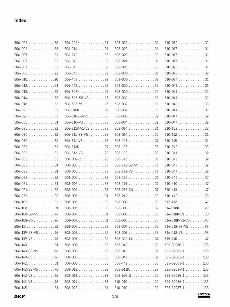
Index
506-006 32
506-006 33
506-007 33
506-007 33
506-007 33
506-008 22
506-010 20
506-012 31
506-013 32
506-014 33
506-018 32
506-025 33
506-026 33
506-030 31
506-030 32
506-030 32
506-030 32
506-032 33
506-032 33
506-032 33
506-033 31
506-033 31
506-033 32
506-034 31
506-034 32
506-056 32
506-101 32
506-108 31
506-108-S8-VS 96
506-108-VS 96
506-114 32
506-139-S8-VS 96
506-139-VS 96
506-140 31
506-140-S8-VS 96
506-140-VS 96
506-142 31
506-142-S8-VS 96
506-142-VS 96
506-143-VS 96
506-145 31
506-202K 29
506-214 31
506-242 33
506-342 32
506-345 32
506-346 32
506-408 22
506-442 33
506-508K 29
506-508-S8-VS 95
506-508-VS 95
506-510K 29
506-510-S8-VS 95
506-510-VS 95
506-511K-V1-VS 95
506-511-S8-VS 95
506-511-VS 95
506-512K 29
506-512-VS 95
508-002-2 22
508-005 33
508-005 33
508-005 33
508-005 33
508-006 31
508-006 31
508-006 33
508-006 33
508-007 31
508-007 31
508-007 32
508-007 32
508-007 32
508-008 32
508-008 32
508-008 33
508-008 33
508-012 32
508-013 33
508-014 33
508-023 31
508-023 31
508-023 31
508-023 33
508-024 31
508-025 33
508-030 31
508-030 32
508-030 32
508-030 32
508-032 33
508-032 33
508-032 33
508-033 32
508-034 32
508-054 31
508-054 32
508-108 37
508-108 128
508-108 128
508-142 31
508-142-S8-VS 96
508-142-VS 96
508-144 31
508-145 31
508-215-CU 37
508-242 33
508-303 32
508-303 32
508-303 33
508-303 33
508-304 32
508-305 33
508-320-CU 37
508-342 32
508-345 32
508-346 32
508-442 33
508-512K 29
508-602-2 22
510-010 32
510-010 32
510-010 32
510-017 31
510-017 31
510-017 31
510-023 31
510-023 32
510-024 31
510-041 31
510-041 32
510-041 32
510-042 33
510-044 31
510-044 32
510-044 32
510-102 22
510-142 31
510-145 31
510-242 33
510-341 32
510-342 32
510-343 32
510-344 32
510-346 32
510-410 47
510-413 47
510-442 33
512-412 47
514-018K 29
514-018K-S1 30
514-018K-V1-VS 95
514-018-S8-VS 95
514-018-VS 95
515-410 47
525-32080-1 133
525-32081-1 133
525-32082-1 133
525-32083-1 133
525-32084-1 133
525-32085-1 133
525-32086-1 133
525-32087-1 133
178

Index
525-32098-1 133
528-31341-3 148
528-36045-6 148
532-32131-1 144
532-32248-1 144
532-32454-1 144
558-012 31
558-012 31
558-012 31
558-012 33
558-012 33
558-012 33
558-612 32
558-612 32
558-612 33
558-612 33
558-812 32
558-812 32
558-812 32
558-812 33
558-812 33
558-912 32
558-912 32
558-912 32
558-912 33
558-913 32
568-342 32
568-442 33
586-342 32
586-442 33
602-001 117
602-002 117
604-001 117
604-002 117
604-003 117
604-004 119
604-014 118
604-015 118
604-016 118
604-018 118
604-36879-1 158
606-010 117
606-014 119
608-001 117
608-003 117
608-004 119
610-001 117
610-004 119
612-001 117
624-25294-1 129
624-25465-1 129
624-25478-1 129
624-25479-1 129
624-25480-1 129
624-25482-1 129
624-25483-1 129
624-27092-1 129
625-25481-1 129
626-25438-2 80
626-25540-2 80
626-25702-1 80
626-25716-2 80
626-25717-2 80
626-25720-2 80
626-26246-1 123
626-26696-2 80
626-26700-2 80
626-26701-2 80
628-25531-2 148
628-26452-2 148
628-36062-3 148
651-28685-1 140
651-28691-1 140
651-29124-1 140
666-34028-2 113
666-34028-3 113
666-34220-1 113
666-34221-5 113
666-34221-9 113
666-34578-5 113
666-34578-9 113
666-34639-5 113
666-36059-8 113
666-36081-7 113
666-36081-8 113
666-36081-9 113
666-36087-1 113
666-36087-2 113
666-36087-3 113
666-36087-7 113
666-36087-8 113
666-36831-9 113
666-85311-1 113
714-180 106
714-180-K 107
714-180-M 106
714-180-MK 107
714-180-M-VS 108
714-180-VS 108
714-220 106
714-220-K 107
714-220-VS 108
714-260 106
714-260-K 107
714-260-M 106
714-260-MK 107
714-260-M-VS 108
714-260-VS 108
714-300 106
714-300-K 107
714-300-M 106
714-300-MK 107
714-300-M-VS 108
714-300-VS 108
714-380 106
714-380-K 107
714-380-VS 108
714-400-M 106
714-400-MK 107
714-400-M-VS 108
714-420 106
714-420-K 107
714-420-VS 108
714-450 106
714-450-K 107
714-450-VS 108
714-500 106
714-500-K 107
714-500-M 106
714-500-MK 107
714-500-M-VS 108
714-500-VS 108
714-580 106
714-580-K 107
714-580-M 106
714-580-MK 107
714-580-M-VS 108
714-580-VS 108
716-220 106
716-220-K 107
716-220-VS 108
716-300 106
716-300-K 107
716-300-M 106
716-300-MK 107
716-300-M-VS 108
716-300-VS 108
716-340 106
716-340-K 107
716-340-VS 108
716-380 106
716-380-K 107
716-380-VS 108
716-400-M 106
716-400-MK 107
716-400-M-VS 108
716-420 106
716-420-K 107
716-420-VS 108
716-450-MK 107
716-450-M-VS 108
716-460-M 106
716-500 106
716-500-K 107
179

Index
716-500-M 106
716-500-MK 107
716-500-M-VS 108
716-500-VS 108
716-580 106
716-580-K 107
716-580-VS 108
718-340 106
718-340-K 107
718-340-VS 108
718-400-M 106
718-400-MK 107
718-400-M-VS 108
718-450 106
718-450-K 107
718-450-M 106
718-450-MK 107
718-450-M-VS 108
718-450-VS 108
718-500-M 106
718-500-MK 107
718-500-M-VS 108
718-580 106
718-580-K 107
718-580-VS 108
734-180 109
734-180-K 109
734-180-VS 110
734-220 109
734-220-K 109
734-220-VS 110
734-260 109
734-260-K 109
734-260-VS 110
734-300 109
734-300-K 109
734-300-VS 110
734-380 109
734-380-K 109
734-380-VS 110
734-420 109
734-420-K 109
734-420-VS 110
734-450 109
734-450-K 109
734-450-VS 110
734-500 109
734-500-K 109
734-500-VS 110
734-580 109
734-580-K 109
734-580-VS 110
843-130-021 74
843-130-022 74
843-130-023 74
844-330-006 154
844-330-007 154
844-330-007 154
853-370-002 115
853-380-002 115
853-380-002-VS 115
853-380-003 115
853-380-003-VS 115
853-380-004 115
853-380-004-VS 115
853-380-006-VS 115
853-380-007-VS 115
853-390-002 115
853-390-002-VS 115
853-390-003 115
853-390-003-VS 115
853-390-004-VS 115
853-390-005-VS 115
853-390-006-VS 115
853-540-010 115
853-750-024 27
855-380-002 115
855-380-002-VS 115
855-380-003 115
855-380-003-VS 115
871-340-006 145
871-340-008 145
871-360-006 145
871-360-008 145
871-380-006 145
871-390-020 145
871-390-023 145
898-510-000 120
898-610-000 120
898-710-000 120
898-710-001 120
902-111 14
904-411 14
906-411 14
908-411 14
910-411 14
912-411 14
917-877 160
941-206-104 119
941-206-108 119
941-208-104 119
941-209-104 119
941-209-105 119
941-210-104 119
941-212-104 119
941-213-104 119
941-215-104 119
941-217-104 119
941-217-105 119
941-218-101 119
941-220-104 119
941-222-100 119
941-225-104 119
941-606-000 120
941-608-000 120
941-610-000 120
982-120-040 104
982-120-041 104
982-120-061 104
982-120-100 104
982-120-180 104
982-760-102 103
982-760-120 103
982-760-122 103
982-760-130 103
982-760-132 103
982-760-142 103
982-760-160 103
982-760-172 103
995-000-705 124
995-000-705 167
995-001-096 124
995-001-104 21
995-001-106 21
995-001-235 124
995-001-260 124
995-001-500 124
995-001-500 167
995-001-501 124
995-001-502 124
995-001-503 124
995-001-504 124
995-001-525 123
995-001-526 123
995-001-620 125
995-001-621 125
995-001-622 125
995-001-623 125
995-001-950 124
995-002-073 124
995-003-040 141
995-003-041 141
995-003-042 141
995-003-043 141
995-003-044 141
995-014-014 26
995-340-000 26
995-340-000-S8 26
995-340-350 26
995-340-350-S8 26
995-350-000 26
995-350-000-S8 26
996-001-890 143
001013 164
180
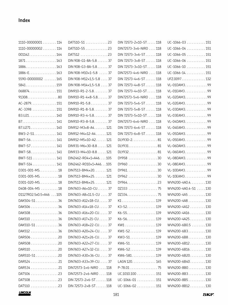
Index
1110-00000001 114
1110-00000002 114
001142 164
1871 163
1886 163
1886-E 163
5590-00000002 165
5841 159
068874 151
91308 80
AC-2879 151
AC-3398 151
B3 U21 140
B7 141
B7 U271 140
BW3-2-S1 141
BW7-S6 141
BW7-S7 141
BW7-S8 141
BW7-S11 141
BW7-S14 141
D301-001-MS 18
D301-005-MS 18
D301-020-MS 18
D408-004-MS 18
D1127RO2 5x0 5+A46 105
DAK504-S1 36
DAK506 36
DAK508 36
DAK510 36
DAK510-S1 36
DAK512 36
DAR506 20
DAR508 20
DAR510 20
DAR510-S1 20
DAR524 21
DAR534 21
DAT506 23
DAT508 23
DAT510 23
DAT510-S1 23
DAT510-S5 23
DAT512 23
DIN 908-G1-8A-5 8 37
DIN 908-G3-8A-5 8 37
DIN 908-M10×1-5 8 37
DIN 908-M12×1,5-5 8 37
DIN 908-M14×1,5-5 8 37
DIN910-R1-2-5 8 37
DIN910-R1-4×8-5 8 37
DIN910-R1-5 8 37
DIN910-R1-8-5 8 37
DIN910-R3-4-5 8 37
DIN910-R3-8-5 8 37
DIN912-M3×8-A4 121
DIN912-M4×12-A4 121
DIN912-M5×10-A2 121
DIN931-M6×30-8 8 121
DIN933-M4×10-8 8 121
DIN2462-RO4×1+A46 105
DIN2462-RO10×1+A46 105
DIN7513-BM4×20 121
DIN7513-BM4×25 121
DIN7513-BM6×25 121
DIN7603-A6×10-CU 37
DIN7603-A8×11 5-CU 37
DIN7603-A12×18-CU 37
DIN7603-A14×18-CU 37
DIN7603-A16×20-CU 37
DIN7603-A17×21-CU 37
DIN7603-A18×22-CU 37
DIN7603-A20×24-CU 37
DIN7603-A21×26-CU 37
DIN7603-A22×27-CU 37
DIN7603-A27×32-CU 37
DIN7603-A30×36-CU 37
DIN7603-A33×39-CU 37
DIN72573-1×6-NIRO 118
DIN72573-2×6-NIRO 118
DIN 72573-2×6-ST 118
DIN 72573-2×8-ST 118
DIN 72573-2×10-ST 118
DIN72573-3×6-NIRO 118
DIN 72573-3×6-ST 118
DIN 72573-3×8-ST 118
DIN 72573-3×10-ST 118
DIN72573-4×6-NIRO 118
DIN 72573-4×6-ST 118
DIN 72573-4×8-ST 118
DIN 72573-4×10-ST 118
DIN72573-5×6-NIRO 118
DIN 72573-5×6-ST 118
DIN 72573-5×8-ST 118
DIN 72573-5×10-ST 118
DIN72573-6×6-NIRO 118
DIN 72573-6×6-ST 118
DIN 72573-6×8-ST 118
DLY930-2 81
DLY931 81
DLY932 81
DY958 30
DY960 30
DY961 30
DY962 30
DY964 23
DZ333 75
DZ334 75
K1 139
K3-S2 139
K6-S5 139
K6-S6 139
KW1 139
KW1-S2 139
KW3-S1 139
KW6-S1 139
KW6-S2 139
KW6-S81 139
LAGN 120 145
P-78 01 75
UC 1010 100 151
UC-1066-01 151
UC-1066-02 151
UC-1066-03 151
UC-1066-04 151
UC-1066-05 151
UC-1066-06 151
UC-1066-10 151
UC-1066-14 151
UFZ 0097 132
VL-01DAM3 99
VL-01EAM3 99
VL-02DAM3 99
VL-02EAM3 99
VL-03DAM3 99
VL-03EAM3 99
VL-04DAM3 99
VL-04EAM3 99
VL-05DAM3 99
VL-05EAM3 99
VL-06DAM3 99
VL-06EAM3 99
VL-08DAM3 99
VL-08EAM3 99
VL-10DAM3 99
VL-10EAM3 99
WVN200-4A0 4 130
WVN200-4A0 4-S1 130
WVN200-4A5 130
WVN200-4A8 130
WVN200-4A12 130
WVN200-4A16 130
WVN200-4A25 130
WVN200-6B0 5 130
WVN200-6B3 130
WVN200-6B8 130
WVN200-6B12 130
WVN200-6B16 130
WVN200-6B20 130
WVN200-6B40 130
WVN200-8B0 130
WVN200-8B3 130
WVN200-8B5 130
WVN200-8B12 130
181
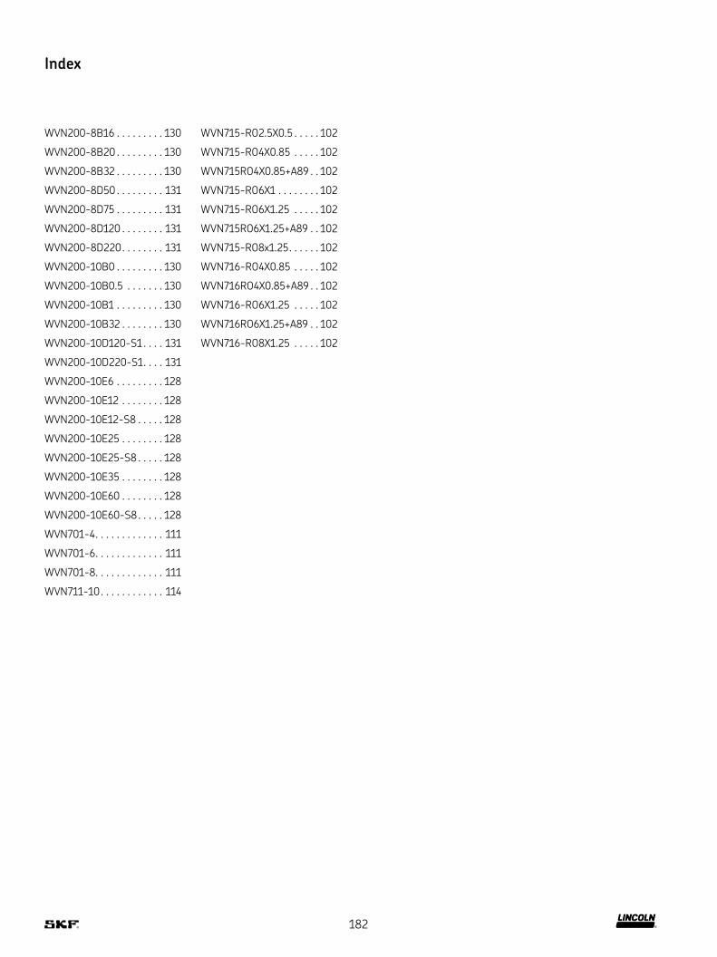
Index
WVN200-8B16 130
WVN200-8B20 130
WVN200-8B32 130
WVN200-8D50 131
WVN200-8D75 131
WVN200-8D120 131
WVN200-8D220 131
WVN200-10B0 130
WVN200-10B0 5 130
WVN200-10B1 130
WVN200-10B32 130
WVN200-10D120-S1 131
WVN200-10D220-S1 131
WVN200-10E6 128
WVN200-10E12 128
WVN200-10E12-S8 128
WVN200-10E25 128
WVN200-10E25-S8 128
WVN200-10E35 128
WVN200-10E60 128
WVN200-10E60-S8 128
WVN701-4 111
WVN701-6 111
WVN701-8 111
WVN711-10 114
WVN715-RO2 5X0 5 102
WVN715-RO4X0 85 102
WVN715RO4X0 85+A89 102
WVN715-RO6X1 102
WVN715-RO6X1 25 102
WVN715RO6X1 25+A89 102
WVN715-RO8x1 25 102
WVN716-RO4X0 85 102
WVN716RO4X0 85+A89 102
WVN716-RO6X1 25 102
WVN716RO6X1 25+A89 102
WVN716-RO8X1 25 102
182
Notes
183

!Important information on product usageSKF and Lincoln lubrication systems or their components are not
approved for use with gases, liquefied gases, pressurized gases in solution and fluids with a vapor pressure exceeding normal atmospheric pressure (1 013 mbar) by more than 0,5 bar at their maximum permissible temperature.
skf com | skf com/lubrication | lincolnindustrial com
® SKF and LINCOLN are registered trademarks of the SKF Group
© SKF Group 2020The contents of this publication are the copyright of the publisher and may not be reproduced (even extracts) unless prior written permission is granted Every care has been taken to ensure the accuracy of the information contained in this publication but no liability can be accepted for any loss or damage whether direct, indirect or consequential arising out of the use of the information contained herein
PUB LS/P1 15859 EN · May 2020
Certain image(s) used under license from Shutterstock com