fittings and accessories - ro-li and accessories for centralised... · 1-0103-en fittings and...
TRANSCRIPT

1-0103-EN
Fittings and Accessoriesfor Centralized Lubrication Systems and General Use
Fittings for solderless tube connections
(double or single tapered rings) are primarily
used for single-line centralized lubrication
systems (oil and grease, NLGI grades 000,
00) with pressures up to 45 bars.
For higher pressures up to 250 bars, like
those occurring especially in progressive
centralized lubrication systems (grease up
to NLGI grade 2), it is customary to use
cutting-sleeve screw unions conforming
to DIN 2353 (Page 18–21).

Fittings and Accessories
31-0103-EN
Adaptors . . . . . . . . . . . . . . . . . . . . . . . . . . . . . . . . . . . . . . . . . 9, 10
Banjo fittings . . . . . . . . . . . . . . . . . . . . . . . . . . . . . . . . . . . . . 17, 19
Bolts . . . . . . . . . . . . . . . . . . . . . . . . . . . . . . . . . . . . . . . . . . . . . . 22
Bracketed connectors . . . . . . . . . . . . . . . . . . . . . . . . . . . . . . . . . 14
Bulkhead connectors . . . . . . . . . . . . . . . . . . . . . . . . . . . . . . . . . . 11
Cone plug . . . . . . . . . . . . . . . . . . . . . . . . . . . . . . . . . . . . . . . . . . 21
Connectors for pressure gauges . . . . . . . . . . . . . . . . . . . . . . 19, 20
Connectors for steel, copper and plastic tubing . . . . . . . . . . . . . . 8
Connectors, tube to tube . . . . . . . . . . . . . . . . . . . . . . . . . . . . . . . 13
Counterbores for solderless tube connection . . . . . . . . . . . . . . . . 7
Coupling plug . . . . . . . . . . . . . . . . . . . . . . . . . . . . . . . . . . . . . . . 36
Cross joints . . . . . . . . . . . . . . . . . . . . . . . . . . . . . . . . . . . . . . . . . 16
Cutting sleeves . . . . . . . . . . . . . . . . . . . . . . . . . . . . . . . . . . . . . . 18
Cutting sleeve screw unions . . . . . . . . . . . . . . . . . . . . . . . . . 18-21
Distributor manifolds . . . . . . . . . . . . . . . . . . . . . . . . . . . . . . . . . 16
Double tapered sleeves . . . . . . . . . . . . . . . . . . . . . . . . . . . . . . . . . 8
Elbow bulkhead connectors . . . . . . . . . . . . . . . . . . . . . . . . . . . . . 19
Elbow connectors . . . . . . . . . . . . . . . . . . . . . . . . . . . . . . . . . . . . 14
Elbow connectors (tube to tube) . . . . . . . . . . . . . . . . . . . . . . . . . 19
Elbows . . . . . . . . . . . . . . . . . . . . . . . . . . . . . . . . . . . . . . . . . 11, 12
Elbow screw-in connectors . . . . . . . . . . . . . . . . . . . . . . . . . . . . . 19
Filler coupling . . . . . . . . . . . . . . . . . . . . . . . . . . . . . . . . . . . . . . . 36
Fixing bolts . . . . . . . . . . . . . . . . . . . . . . . . . . . . . . . . . . . . . . . . . 22
Fixing clips . . . . . . . . . . . . . . . . . . . . . . . . . . . . . . . . . . . . . . . . . 23
Flat washers . . . . . . . . . . . . . . . . . . . . . . . . . . . . . . . . . . . . . . . . 12
Form counterbores . . . . . . . . . . . . . . . . . . . . . . . . . . . . . . . . . . . . 7
Four-way connectors . . . . . . . . . . . . . . . . . . . . . . . . . . . . . . . . . 19
High-pressure hoses . . . . . . . . . . . . . . . . . . . . . . . . . . . . . . . . . . 27
Hoses for main and secondary lines . . . . . . . . . . . . . . . . . . . . . . 26
Hoses suitable for self-installation . . . . . . . . . . . . . . . . . . . . . . . 26
Lock washers . . . . . . . . . . . . . . . . . . . . . . . . . . . . . . . . . . . . . . . 22
Contents
Nuts . . . . . . . . . . . . . . . . . . . . . . . . . . . . . . . . . . . . . . . . . . . . . . 22
Oil reservoirs . . . . . . . . . . . . . . . . . . . . . . . . . . . . . . . . . . . . . 34, 35
Plastic tubing . . . . . . . . . . . . . . . . . . . . . . . . . . . . . . . . . . . . . . . 25
Pressure gauges . . . . . . . . . . . . . . . . . . . . . . . . . . . . . . . . . . . . . 29
Quick-disconnect couplings . . . . . . . . . . . . . . . . . . . . . . . . . . . . . 30
Reducing adapters . . . . . . . . . . . . . . . . . . . . . . . . . . . . . . . . . . . 10
Reducing connectors . . . . . . . . . . . . . . . . . . . . . . . . . . . . . . . 18, 21
Reinforcing sockets . . . . . . . . . . . . . . . . . . . . . . . . . . . . . . . . . . . . 8
Relief valves . . . . . . . . . . . . . . . . . . . . . . . . . . . . . . . . . . . . . . . . 31
Rotating joints . . . . . . . . . . . . . . . . . . . . . . . . . . . . . . . . . . . . . . . 28
Safety valves . . . . . . . . . . . . . . . . . . . . . . . . . . . . . . . . . . . . . 32, 33
Screw plugs . . . . . . . . . . . . . . . . . . . . . . . . . . . . . . . . . . . . . 12, 21
Shut-off valves . . . . . . . . . . . . . . . . . . . . . . . . . . . . . . . . . . . . . . 30
Socket unions . . . . . . . . . . . . . . . . . . . . . . . . . . . . . . . . . . . . . . . . 8
Steel tubing . . . . . . . . . . . . . . . . . . . . . . . . . . . . . . . . . . . . . . . . . 24
Straight bulkhead connectors . . . . . . . . . . . . . . . . . . . . . . . . 19, 20
Straight connectors (tube to tube) . . . . . . . . . . . . . . . . . . . . 18, 20
Straight screw-in connectors . . . . . . . . . . . . . . . . . . . . . . . . 18, 20
Straight screw-in glands . . . . . . . . . . . . . . . . . . . . . . . . . . . . . . . 18
Tapered sleeves . . . . . . . . . . . . . . . . . . . . . . . . . . . . . . . . . . . . . . 8
Tee connectors . . . . . . . . . . . . . . . . . . . . . . . . . . . . . . . 15, 19, 20
Threaded sockets . . . . . . . . . . . . . . . . . . . . . . . . . . . . . . . . . . . . 13
Topping-up pumps . . . . . . . . . . . . . . . . . . . . . . . . . . . . . . . . . . . 36
Tube-to-tube connector with air vent . . . . . . . . . . . . . . . . . . . . . 14
Tubing . . . . . . . . . . . . . . . . . . . . . . . . . . . . . . . . . . . . . . . . . . . . . 24
Union nuts . . . . . . . . . . . . . . . . . . . . . . . . . . . . . . . . . . . . . . . . . 18
Vent plugs . . . . . . . . . . . . . . . . . . . . . . . . . . . . . . . . . . . . . . . 12, 21
Washers . . . . . . . . . . . . . . . . . . . . . . . . . . . . . . . . . . . . . . . . . . . 12
See important product usage information
on the back cover.
Fittings and Accessories
4 1-0103-EN
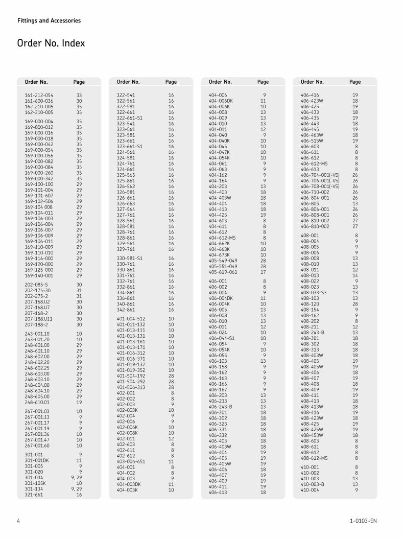
Order No. Index
161-212-054 33
161-600-036 30
162-210-005 35
162-310-005 35
169-000-004 35
169-000-012 35
169-000-016 35
169-000-018 35
169-000-042 35
169-000-054 35
169-000-056 35
169-000-082 35
169-000-084 35
169-000-260 35
169-000-342 35
169-100-100 29
169-101-004 29
169-101-607 29
169-102-506 29
169-104 008 29
169-104-011 29
169-106-003 29
169-106-004 29
169-106-007 29
169-106-009 29
169-106-011 29
169-110-009 29
169-110-010 29
169-116-000 29
169-120-000 29
169-125-000 29
169-140-001 29
202-085-S 30
202-175-30 31
202-275-2 31
207-168.U2 30
207-168.U7 30
207-168-2 30
207-188.U11 30
207-188-2 30
243-001.10 10
243-001.20 10
248-601.00 29
248-601.10 29
248-602.00 29
248-602.20 29
248-602.25 29
248-603.00 29
248-603.10 29
248-604.00 29
248-604.10 29
248-605.00 29
248-610.01 19
267-001.03 10
267-001.13 9
267-001.17 9
267-001.19 9
267-001.36 10
267-001.47 10
267-001.60 10
301-001 9
301-001DK 11
301-005 9
301-020 9
301-034 9, 29
301-105K 10
301-134 9, 29
321-661 16
322-541 16
322-561 16
322-581 16
322-661 16
322-661-S1 16
323-541 16
323-561 16
323-581 16
323-661 16
323-661-S1 16
324-561 16
324-581 16
324-761 16
324-861 16
325-565 16
325-861 16
326-562 16
326-581 16
326-661 16
326-663 16
327-564 16
327-761 16
328-561 16
328-581 16
328-761 16
328-861 16
329-561 16
329-761 16
330-581-S1 16
330-761 16
330-861 16
331-761 16
332-761 16
332-861 16
334-861 16
336-861 16
340-861 16
342-861 16
401-004-512 10
401-011-132 10
401-013-111 10
401-013-131 10
401-013-161 10
401-013-171 10
401-016-312 10
401-016-371 10
401-019-132 10
401-019-352 10
401-504-192 28
401-504-292 28
401-506-313 28
402-001 8
402-002 8
402-003 9
402-003K 10
402-004 9
402-006 9
402-006K 10
402-008K 10
402-011 12
402-603 8
402-611 8
402-612 8
403-006-651 11
404-001 8
404-002 8
404-003 9
404-003DK 11
404-003K 10
404-006 9
404-006DK 11
404-006K 10
404-008 13
404-009 13
404-010 13
404-011 12
404-040 9
404-040K 10
404-045 10
404-047K 10
404-054K 10
404-061 9
404-063 9
404-162 9
404-164 9
404-203 13
404-403 18
404-403W 18
404-404 18
404-413 18
404-425 19
404-603 8
404-611 8
404-612 8
404-612-MS 8
404-662K 10
404-663K 10
404-673K 10
405-549-049 28
405-551-049 28
405-619-061 17
406-001 8
406-002 8
406-004 9
406-004DK 11
406-004K 10
406-005 13
406-008 13
406-010 13
406-011 12
406-024 10
406-044-S1 10
406-054 9
406-054K 10
406-055 9
406-103 13
406-158 9
406-162 9
406-163 9
406-166 9
406-167 9
406-203 13
406-233 13
406-243-B 13
406-301 18
406-302 18
406-323 18
406-331 18
406-332 18
406-403 18
406-403W 18
406-404 19
406-405 19
406-405W 19
406-406 18
406-407 19
406-409 19
406-411 19
406-413 18
406-416 19
406-423W 18
406-425 19
406-433 18
406-435 19
406-443 18
406-445 19
406-463W 18
406-515W 19
406-603 8
406-611 8
406-612 8
406-612-MS 8
406-613 8
406-704-001(-VS) 26
406-706-001(-VS) 26
406-708-001(-VS) 26
406-710-002 26
406-804-001 26
406-805 13
406-806-001 26
406-808-001 26
406-810-002 27
406-810-002 27
408-001 8
408-004 9
408-005 9
408-006 9
408-008 13
408-010 13
408-011 12
408-013 14
408-022 9
408-023 13
408-033-S3 13
408-103 13
408-120 28
408-154 9
408-162 9
408-202 8
408-211 12
408-243-B 13
408-301 18
408-302 18
408-313 18
408-403W 18
408-405 19
408-405W 19
408-406 18
408-407 19
408-408 18
408-409 19
408-411 19
408-413 18
408-413W 18
408-416 19
408-423W 18
408-425 19
408-425W 19
408-453W 18
408-603 8
408-611 8
408-612 8
408-612-MS 8
410-001 8
410-002 8
410-003 13
410-003-B 13
410-004 9
Order No. Page Order No. Page Order No. Page Order No. Page
Fittings and Accessories
51-0103-EN
410-004DK 11
410-160 9
410-162 9
410-163 9
410-164 9
410-171 9
410-301 18
410-302 18
410-313 18
410-323 18
410-403 18
410-403W 18
410-404 19
410-405 19
410-405W 19
410-406 18
410-407 19
410-408 18
410-409 19
410-410 18
410-411 19
410-413 18
410-413W 18
410-416 19
410-425 19
410-433W 18
410-443 18
410-443W 18
410-463 18
410-603 8
410-611 8
410-612 8
410-612-MS 8
412-001 8
412-002 8
412-004 9
412-008 13
412-010 13
412-011 12
412-014 9
412-162 9
412-163 9
412-164 9
412-301 18
412-302 18
412-403 18
412-403W 18
412-404 19
412-405 19
412-405W 19
412-407 19
412-409 19
412-410 18
412-411 19
412-412 18
412-416 19
412-423 18
412-423W 18
412-433 18
412-453 18
412-453W 18
412-603 8
412-611 8
412-612 8
415-403 18
415-403W 18
415-405 19
415-405W 19
415-407 19
415-409 19
415-410 18
415-415 18
415-416 19
415-423W 18
415-433W 18
415-443W 18
418-403 18
418-403W 18
418-405W 19
418-407 19
418-409 19
418-412 18
418-416 19
418-418 18
422-407 19
422-412 18
422-416 19
433-890-131 10
441-008-511 18
441-015-171 18
441-022-171 18
441-106-162 19
441-106-163 20
441-108-162 19
441-110-163 19
441-112-162 19
443-190-901 19
443-215-001 19
443-218-001 19
443-290-001 19
443-706-121 18
443-706-151 18
443-706-181 18
443-708-121 18
443-708-151 18
443-708-181 18
443-710-061 18
443-710-181 18
443-712-151 18
443-715-181 18
445-513-181 19
445-516-061 19
445-516-081 19
445-516-101 19
445-517-222 19
445-519-041 19
445-519-061 19
445-521-122 19
445-529-041 19
445-531-061 19
445-535-101 19
446-308-001 19
446-310-001 19
446-312-001 19
446-315-001 19
456-004K 10
458-012 13
458-012-B 13
460-706-001 21
460-708-001 21
460-710-001 21
460-712-001 21
466-411-001 21
466-413-001 21
466-416-001 21
466-418-001 21
466-419-001 21
466-431-001 21
466-431-005 21
466-431-006 21
466-431-009 21
466-435-003 21
466-439-001 21
471-004-191 20
471-004-311 20
471-006-161 20
471-006-192 20
471-006-311 20
471-006-351 20
471-008-161 20
471-008-211 20
471-008-351 20
471-008-391 20
471-010-161 20
471-010-211 20
471-010-312 20
471-010-351 20
471-010-391 20
471-012-161 20
471-012-211 20
471-012-391 20
471-015-131 20
471-108-163 20
471-110-163 20
471-112-163 20
473-806-351 21
473-806-391 21
473-808-371 21
473-808-392 21
473-810-371 21
473-810-391 21
474-506-061 20
474-508-081 20
474-510-101 20
474-512-121 20
474-515-151 20
474-518-181 20
474-606-331 20
474-608-351 20
474-610-351 20
474-612-391 20
474-615-431 20
474-618-441 20
476-006-001 20
476-008-001 20
476-010-001 20
476-012-001 20
476-015-001 20
502-101 17
502-102 17
502-161 17
502-206K 11
504-003 14
504-004 14
504-008 15
504-019 12
504-045 15
504-101 17
504-102 17
504-103 14
504-105 17
504-106 17
504-108 17
504-109 17
504-110 17
504-111 17
504-112 17
504-114 17
504-115 17
504-161 17
504-162 17
504-200K 11
504-201K 11
504-202K 11
504-203K 11
504-401 17
504-410 18
504-411 17
504-412 18
504-510K 11
506-004 14
506-008 15
506-010 14
506-012 17
506-013 17
506-014 17
506-025 17
506-026 17
506-101 17
506-108 17
506-114 17
506-140 17
506-142 17
506-145 17
506-202K 11
506-214 17
506-242 17
506-342 17
506-345 17
506-346 17
506-408 15
506-410 18
506-412 18
506-413 18
506-442 17
506-508K 11
506-510K 11
506-512K 11
508-002-2 15
508-012 17
508-013 17
508-014 17
508-024 17
508-025 17
508-034 17
508-108 12
508-142 17
508-144 17
508-145 17
508-215-CU 12
508-242 17
508-304 17
508-305 17
508-320-CU 12
508-342 17
508-345 17
508-346 17
508-410 18
508-412 18
508-413 18
508-442 17
508-512K 11
508-602-2 15
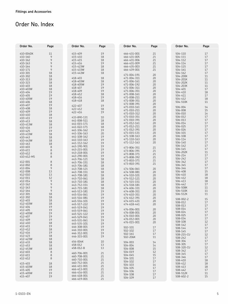
Order No. Index
Order No. Page Order No. Page Order No. Page Order No. Page
Fittings and Accessories
6 1-0103-EN
510-024 17
510-102 15
510-142 17
510-145 17
510-242 17
510-341 17
510-342 17
510-343 17
510-344 17
510-346 17
510-410 18
510-412 18
510-413 18
510-442 17
512-410 18
512-412 18
514-018K 11
515-410 18
568-342 17
568-442 17
586-342 17
586-442 17
602-001 23
602-002 23
604-001 23
604-002 23
604-003 23
604-004 23
604-014 23
604-015 23
604-016 23
604-018 23
606-010 23
606-014 23
608-001 23
608-003 23
608-004 23
610-001 23
610-004 23
612-001 23
650-050 22
650-060 22
650-080 22
650-100 22
650-120 22
650-140 22
650-160 22
650-180 22
650-200 22
714-...(-VS) 26
714-...-M(-VS) 26
714-...-MK 26
716-...(-VS) 26
716-...-M(-VS) 26
716-...-MK 26
718-...(-VS) 26
718-...-M (-VS) 26
718-...-MK 26
734-... 26
734-...-K 26
734-...-VS 26
833-330-016 12
833-330-021 12
853-370-002(-VS) 27
853-380-002(-VS) 27
853-380-003(-VS) 27
853-380-004(-VS) 27
853-390-002(-VS) 27
853-390-003(-VS) 27
853-540-010 27
853-750-024 13
902-111 7
904-411 7
906-411 7
908-411 7
910-411 7
912-411 7
96-0408-0058 19
96-0718-0058 19
96-2106-0058 19
96-6904-0058 19
982-120-040 24
982-120-060 24
982-120-080 24
982-120-100 24
982-120-120 24
982-120-150 24
982-120-180 24
982-750-091 27
982-750-091+AF2 27
995-000-705 36
995-001-104 14
995-001-106 14
995-001-260 36
995-001-501 36
995-001-502 36
995-003-044 35
995-003-040 35
995-003-041 35
995-003-042 35
995-003-043 35
B3-S1 35
B7 35
BW3-S81 35
BW3-S9 35
BW7-S11 35
BW7-S12 35
BW7-S6 35
BW7-S7 35
BW7-S8 35
D301-001-MS 9
D301-005-MS 9
D301-020-MS 9
D406-004-MS 9
D408-004-MS 9
DAK504-S1 16
DAK506 16
DAK508 16
DAK510 16
DAK510-S1 16
DAK512 16
DAR506 14
DAR508 14
DAT506 15
DAT508 15
DAT510 15
DAT510-S5 15
DAT512 15
DIN72573-2×10-ST 23
DIN72573-2×6-ST 23
DIN72573-2×8-ST 23
DIN72573-3×10-ST 23
DIN72573-3×6-ST 23
DIN72573-3×8-ST 23
DIN72573-4×10-ST 23
DIN72573-4×6-ST 23
DIN72573-4×8-ST 23
DIN72573-5×10-ST 23
DIN72573-5×6-ST 23
DIN72573-5×8-ST 23
DIN72573-6×6-ST 23
DIN72573-6×8-ST 23
DIN7513-BM4×20 22
DIN7513-BM4×25 22
DIN7513-BM5×10 22
DIN7513-BM6×16 22
DIN7513-BM6×25 22
DIN7603-A14×18-CU 12
DIN7603-A16×20-CU 12
DIN7603-A17×21-CU 12
DIN7603-A18×22-CU 12
DIN7603-A20×24-CU 12
DIN7603-A21×26-CU 12
DIN7603-A22×27-CU 12
DIN7603-A6×10-CU 12
DIN7603-A8×11,5-CU 12
DIN84-M3×5-4.8 22
DIN84-M5×16-4.8 22
DIN84-M5×20-4.8 22
DIN84-M5×8-4.8 22
DIN84-M6×16-4.8 22
DIN84-M6×20-4.8 22
DIN84-M6×25-4.8 22
DIN910-R1-2-5.8 12
DIN910-R1-4×8-5.8 12
DIN910-R1-5.8 12
DIN910-R1-8-5.8 12
DIN910-R3-4-5.8 12
DIN910-R3-8-5.8 12
DIN912-M4×20-8.8 22
DIN912-M6×16-8.8 22
DIN912-M6×25-8.8 22
DIN912-M6×60-8.8 22
DIN912-M8×16-8.8 22
DIN931-M6×30-5.8 22
DIN934-M5-8 22
DIN934-M6-8 22
DIN936-M14×1.5-5 22
DIN936-M16×1.5-5 22
DIN936-M20×1.5-5 22
DLY930-2 27
DLY931 27
DLY932 27
DY958 12
DY960 12
DY961 12
DY962 12
DY964 15
DY966 15
DZ333 10
DZ334 10
K1 34
K3-S2 34
K6-S5 34
KW1 34
KW1-S2 34
KW3-S1 34
KW3-S3 34
KW3-S5 34
KW6-S1 34
KW6-S2 34
KW6-S81 34
KW6-V57 34
P-78.01 10
SLH10-180 27
SLH6-180 27
SLH8-180 27
WVN200-10D120-S1 33
WVN200-10D220-S1 33
WVN200-10E12 32
WVN200-10E25 32
WVN200-10E35 32
WVN200-10E6 32
WVN200-10E60 32
WVN200-4A0.4 33
WVN200-4A0.4-S1 33
WVN200-4A12 33
WVN200-4A16 33
WVN200-4A25 33
WVN200-4A5 33
WVN200-4A8 33
WVN200-6B0.5 33
WVN200-6B12 33
WVN200-6B16 33
WVN200-6B20 33
WVN200-6B3 33
WVN200-6B40 33
WVN200-6B8 33
WVN200-8B0 33
WVN200-8B12 33
WVN200-8B16 33
WVN200-8B20 33
WVN200-8B3 33
WVN200-8B32 33
WVN200-8B5 33
WVN200-8D120 33
WVN200-8D220 33
WVN200-8D50 33
WVN200-8D75 33
WVN701-4 26
WVN701-6 26
WVN701-8 26
WVN711-10 27
WVN711-10+AF2 27
WVN715-RO10×1.5 25
WVN715-RO12×1 25
WVN715-RO12×1.5 25
WVN715-RO2.5×0.5 25
WVN715-RO4×0.85 25
WVN715-RO6×1 25
WVN715-RO6×1.25 25
WVN715-RO8×1.25 25
WVN716-RO4×0.85 25
WVN716-RO6×1.25 25
WVN716-RO8×1.25 25
WV-RO10×1 VERZI 24
WV-RO2.5×0.5 VERZI 24
WV-RO4×0.7 VERZI 24
WV-RO6×0.7 VERZI 24
WV-RO6×1 VERZI 24
WV-RO8×0.7 VERZI 24
WV-RO8×1 VERZI 24
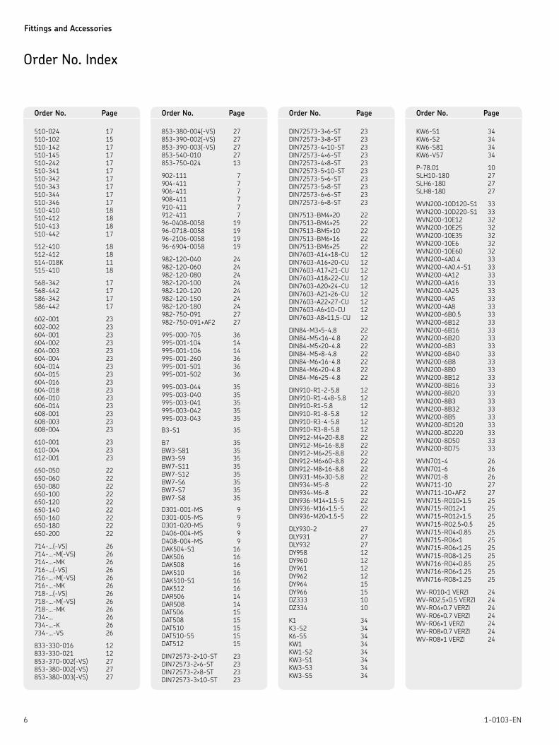
Order No. Index
Order No. Page Order No. Page Order No. Page Order No. Page
Fittings and Accessories
71-0103-EN
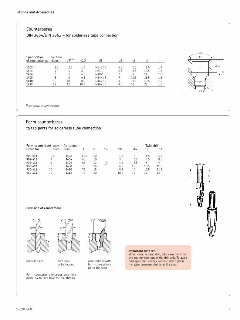
Counterbores
DIN 3854/DIN 3862 – for solderless tube connection
Specification for tubeof counterbores diam. d9B11 d10 d8 b3 t3 t4 r
1102 1) 2.5 2.5 1.5 M6 ×0.75 4.5 5.5 8.5 1.3
1404 4 4 3 M8×1 6.5 8.5 12.5 1.6
1406 6 6 4.5 M10×1 7 9 14 1.6
1408 8 8 6.5 M14 ×1.5 9 11.5 18.5 1.6
1410 10 10 8.5 M16 ×1.5 9 11.5 19.5 1.6
1412 12 12 10.5 M18 ×1.5 9.5 12 22 1.6
1) not shown in DIN standard
90°
d8
d9
d10
r
b3 t3t4
Form counterbores
to tap ports for solderless tube connection
Form counterbore tube for counter- Twist drillOrder No. diam. bore l d1 d2 d10 d4 t2 t3
902-111 2.5 1102 60.5 10 1.5 5 4.5 5.5
904-411 4 1404 65 10 3 6.5 7.5 8.5
906-411 6 1406 66 12 10 4.5 8.5 8 9
908-411 8 1408 70 16 6.5 12 10.5 11.5
910-411 10 1410 72 18 8.5 14 10.5 11.5
912-411 12 1412 75 20 10.5 16 11 12
Provision of counterbore
predrill holes bore hole counterbore with to be tapped form counterbore up to the stop Form counterbore enlarges bore holediam. d4 to core hole for ISO thread.
Important note #3: When using a hand drill, take care not to tilt the counterbore out of the drill axis. To avoid damages drill steadily without interruption. Increase pressure slightly at the stop.
Fittings and Accessories
8 1-0103-EN
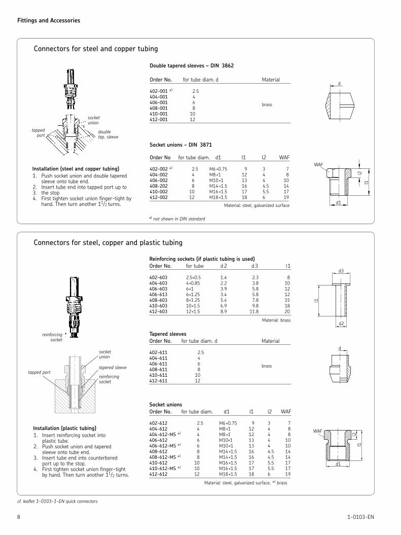
Connectors for steel and copper tubing
socketunion
doubletap. sleeve
tappedport
Installation (steel and copper tubing)
Push socket union and double tapered 1. sleeve onto tube end.Insert tube end into tapped port up to 2. the stop3. First tighten socket union finger-tight by 4. hand. Then turn another 11/2 turns.
Connectors for steel, copper and plastic tubing
Installation (plastic tubing)
Insert reinforcing socket into 1. plastic tube.Push socket union and tapered2. sleeve onto tube end.Insert tube end into counterbored 3. port up to the stop.First tighten socket union finger-tight 4. by hand. Then turn another 11/2 turns.
reinforcing socket
socketunion
tapered sleeve
reinforcingsocket
tapped port
Reinforcing sockets (if plastic tubing is used)
Order No. for tube d 2 d 3 l1
402-603 2.5×0.5 1.4 2.3 8
404-603 4×0.85 2.2 3.8 10
406-603 6×1 3.9 5.8 12
406-613 6×1.25 3.4 5.8 12
408-603 8×1.25 5.4 7.8 15
410-603 10×1.5 6.9 9.8 18
412-603 12×1.5 8.9 11.8 20
Material: brass
Tapered sleeves
Order No. for tube diam. d Material
402-611 2.5
404-611 4
406-611 6 brass408-611 8
410-611 10
412-611 12
Socket unions
Order No. for tube diam. d1 l1 l2 WAF
402-612 2.5 M6 ×0.75 9 3 7
404-612 4 M8 ×1 12 4 8
404-612-MS *) 4 M8 ×1 12 4 8
406-612 6 M10×1 13 4 10
406-612-MS *) 6 M10 ×1 13 4 10
408-612 8 M14 ×1.5 16 4.5 14
408-612-MS *) 8 M14 ×1.5 16 4.5 14
410-612 10 M16 ×1.5 17 5.5 17
410-612-MS *) 10 M16 ×1.5 17 5.5 17
412-612 12 M18 ×1.5 18 6 19
Material: steel, galvanized surface, *) brass
Double tapered sleeves – DIN 3862
Order No. for tube diam. d Material
402-001 *) 2.5
404-001 4
406-001 6 brass408-001 8
410-001 10
412-001 12
Socket unions – DIN 3871
Order No for tube diam. d1 l1 l2 WAF
402-002 *) 2.5 M6 ×0.75 9 3 7
404-002 4 M8 ×1 12 4 8
406-002 6 M10 ×1 13 4 10
408-202 8 M14 ×1.5 16 4.5 14
410-002 10 M16 ×1.5 17 5.5 17
412-002 12 M18 ×1.5 18 6 19
Material: steel, galvanized surface
*) not shown in DIN standard
cf. leaflet 1-0103-1-EN quick connectors
Fittings and Accessories
91-0103-EN
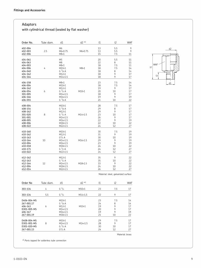
Adaptors
with cylindrical thread (sealed by flat washer)
Order No. Tube diam. d1 d2 *) l1 l2 WAF
402-004 M6 13 5.5 9
402-003 2.5 M6×0.75 M6×0.75 13 5.5 9
402-006 M8×1 15 7.5 11
404-061 M5 20 5.5 11
404-063 M8 22 8 11
404-003 M8×1 18 7.5 11
404-006 4 M10×1 M8×1 18 7.5 14
404-040 G 1/8 A 18 8 14
404-162 M12×1 18 9 17
404-164 M14×1.5 18 9 17
406-158 M8×1 23 7.5 14
406-004 M10×1 18 7.5 14
406-162 M12×1 19 9 17
406-054 6 G 1/4 A M10×1 20 10 17
301-005 M14×1.5 18 9 17
406-166 M16×1.5 19 9 19
406-055 G 3/8 A 21 10 22
408-004 M10×1 28 7.5 17
408-154 G 1/8 A 29 8 17
408-162 M12×1 29 9 17
301-020 8 G 1/4 A M14×1.5 23 10 17
301-001 M14×1.5 26 9 17
408-005 M16×1.5 22 9 19
408-006 M18×1.5 22 10 22
408-022 M22×1.5 24 12 27
410-160 M10×1 30 7.5 19
410-162 M12×1 31 9 19
410-163 G1/4 A 30 10 19
410-164 10 M14×1.5 M16×1.5 29 9 19
410-004 M16×1.5 23 9 19
410-018 M18×1.5 24 10 22
410-171 G 1/2 A 24 12 27
410-022 M22×1.5 24 12 27
412-162 M12×1 35 9 22
412-163 G 1/4 A 35 10 22
412-164 12 M14×1.5 M18×1.5 33 9 22
412-004 M18×1.5 24 10 22
412-014 M22×1.5 26 12 27
Material: steel, galvanized surface
Order No Tube diam. d1 d2 *) l1 l2 WAF
303-134 4 G 1/4 M10×1 23 7,5 17
303-134 5,5 G 1/4 M14×1,5 22 9 17
D406-004-MS M10×1 23 7.5 14
267-001.17 G 1/8 A 24 8 14
406-163 6 M12×1 M10×1 19 9 17
D301-005-MS M14×1.5 20 9 17
406-167 M16×1.5 19 9 19
267-001.19 M18×1.5 21 10 22
D408-004-MS M10×1 29 7.5 17
D301-001-MS 8 M14×1.5 M14×1.5 28 9 17
D301-020-MS G 1/4 A 30 10 17
267-001.13 G1/2 A 24 12 27
Material: brass
*) Ports tapped for solderless tube connection

Fittings and Accessories
10 1-0103-EN
Reducing adapters
with cylindrical thread (sealed by flat washer)
Order No. d1 d2 l1 l2 WAF Material
406-024 M10×1 G 1/8 20 8 14 brass. galvanized surface
401-016-312 M10×1 G 1/4 26.5 7.5 17 brass
406-044-S11) M10×1 tap. G 1/4 22.5 8 17 steel, galvanized surface
P-78.01 M12×1 G 1/4 27 8.5 19 steel, galvanized surface
401-013-161 G 1/4 A G 1/2 40 12 27 steel, galvanized surface
401-019-352 M14×1.5 G 1/8 20 9 17 brass
401-016-371 M16×1.5 G 1/4 30 12 19 steel, galvanized surface
243-001.10 M16×1.5 G 1/2 31 9 27
267-001.47 G 3/8 A G 1/4 31 10 22 brass267-001.60 G 3/8 A G 1/2 34 27
267-001.36 M18×1.5 G 3/8 32 10 22 steel, galvanized surface243-001.20 M18×1.5 G 1/2 27
401-019-132 G 1/8 24 27
DZ333 G 1/4 24 27
401-013-131 G 1/2 A G 1/2 40.5 12 27 brass
DZ334 G 3/8 31 27
267-001.03 G 3/4 40 36
401-011-132 G 1/2 A G 1 49 14 41
433-890-131 G 1/2 A G 1 1/4 53 14 55 steel, galvanized surface401-013-171 G 3/4 A G 1/2 41 16 32
401-013-111 G 1 A G 1/2 29 18 41
1) with tapered thread
Adaptors
with tapered thread
Tapered threads are used without washers, as they are self-sealing.It is not necessary to provide the ports with seal faces.
Order No. Tube diam. d1 1) d2 *
) l1 l2 WAF Material
402-003K M6 ×0,75 tap. 11.5 4.5 8
402-006K 2.5 M8 ×1 tap. M6×0.75 15 8 9
402-008K M10×1 tap. 16 7.5 12
404-662K M6 tap. 19 5 11
404-663K M6 tap. 20 6 11
404-673K M6×0.75 tap. 20 6 11
404-047K M7 tap. 20 6 11
404-003K 4 M8×1 tap. M8 ×1 17 7.4 11 steel, galvanized surface404-045 M8×1 tap. 62.5 7.4 11
404-006K M10×1 tap. 16 7.4 11
401-004-512 M10×1 tap. 25 7.4 11
404-040K R 1/8 tap. 16 6 11
404-054K R 1/8 tap. 14 9 14
406-004K M10×1 tap. 23 7.4 14
301-105K 6 M12×1 tap. M10×1 18 7.4 14
456-004K R 1/8 tap. 21 6 14
406-054K R 1/8 tap. 20 9 17
1) Tapered thread according to DIN 158. short, resp. according to DIN 2999
*) Ports tapped for solderless tube connection
Fittings and Accessories
111-0103-EN
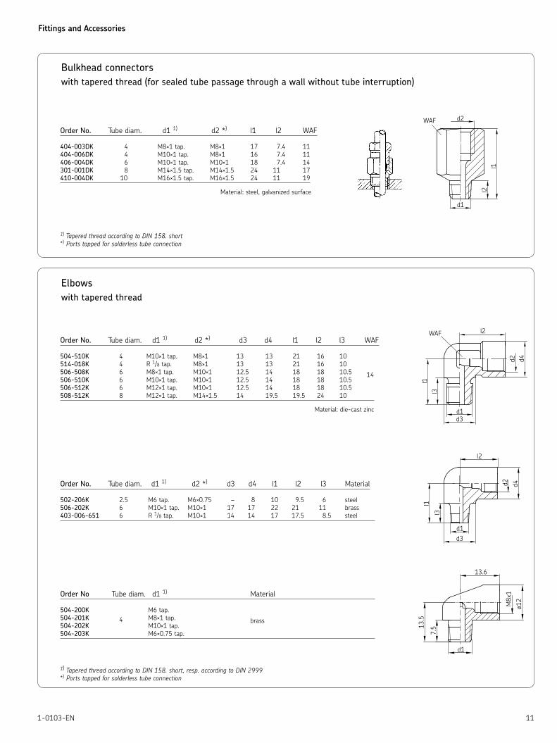
Bulkhead connectors
with tapered thread (for sealed tube passage through a wall without tube interruption)
Order No. Tube diam. d1 1) d2 *) l1 l2 WAF
404-003DK 4 M8×1 tap. M8×1 17 7.4 11
404-006DK 4 M10×1 tap. M8×1 16 7.4 11
406-004DK 6 M10×1 tap. M10×1 18 7.4 14
301-001DK 8 M14×1.5 tap. M14×1.5 24 11 17
410-004DK 10 M16×1.5 tap. M16×1.5 24 11 19
Material: steel, galvanized surface
1) Tapered thread according to DIN 158. short
*) Ports tapped for solderless tube connection
Elbows
with tapered thread
Order No. Tube diam. d1 1) d2 *) d3 d4 l1 l2 l3 WAF
504-510K 4 M10×1 tap. M8×1 13 13 21 16 10
514-018K 4 R 1/8 tap. M8×1 13 13 21 16 10
506-508K 6 M8×1 tap. M10×1 12.5 14 18 18 10.5 14506-510K 6 M10×1 tap. M10×1 12.5 14 18 18 10.5
506-512K 6 M12×1 tap. M10×1 12.5 14 18 18 10.5
508-512K 8 M12×1 tap. M14×1.5 14 19.5 19.5 24 10
Material: die-cast zinc
Order No. Tube diam. d1 1) d2 *) d3 d4 l1 l2 l3 Material
502-206K 2.5 M6 tap. M6×0.75 – 8 10 9.5 6 steel
506-202K 6 M10×1 tap. M10×1 17 17 22 21 11 brass
403-006-651 6 R 1/8 tap. M10×1 14 14 17 17.5 8.5 steel
Order No Tube diam. d1 1) Material
504-200K M6 tap.
504-201K 4 M8×1 tap. brass504-202K M10×1 tap.
504-203K M6×0.75 tap.
1) Tapered thread according to DIN 158. short, resp. according to DIN 2999
*) Ports tapped for solderless tube connection

Fittings and Accessories
12 1-0103-EN
Elbows
with tube end (for installation in counterbores as per DIN 3854/DIN 3862)
Order No. Tube diam. d1 d2 *) d3 d4 l1 l2 l3
DY958 6 6 M10×1 8 14 30.8 21 22
DY960 8 8 M14×1.5 11 18 37 24.5 27
DY961 10 10 M16×1.5 15 23 42.5 26.5 29
DY962 12 12 M18×1.5 15 23 46 26.5 32
Tube end for tube connection Material: brass
*) Ports tapped for solderless tube connection
Screw plugs
Order No. d1 d2 l1 l2 l3 WAF Material
DIN910-R1-8-5.8 G 1/8 A 14 17 8 3 11
DIN910-R1-4×8-5.8 G 1/4 A 18 17 8 3 14 steel, DIN910-R3-8-5.8 G 3/8 A 22 21 12 3 17 galvanized surfaceDIN910-R1-2-5.8 G 1/2 A 26 26 14 4 19
DIN910-R3-4-5.8 G 3/4 A 32 30 16 4 24
DIN910-R1-5.8 G 1 A 39 32 16 5 27
402-011 M6×0.75 9 5 9
404-011 M8×1 10 6 11
406-011 M10×1 12 7 12 steel,
408-211 M12×1 12 7 17 galvanized surface
408-011 M14×1.5 12 7 17
410-011 M16×1.5 14 8 19
412-011 M18×1.5 15 10 22
Vent plugs
Order No. d1 d2 l1 l2 l3 WAF Material
833-330-016 M 10×1 14 17 8 3 11 steel, 833-330-021 G 1/8 A galvanized surface
Flat washers
Suitable for threadOrder No. d1 d2 h mm inches Material
DIN7603-A6×10-CU 6.2 9.9 1 M6 –
DIN7603-A8×11.5-CU 8.2 11.4 1 M8 –
504-019 10.2 13.9 1 M10 G 1/8 copper
508-215-CU 12.2 15.9 1.4 M12 –
508-320-CU 12.2 15.9 2 M12 –
DIN7603-A14×18-CU 14.2 17.9 M14 –
508-108 13.3 17.9 – G 1/4
DIN7603-A16×20-CU 16.2 19.9 M16 –
DIN7603-A17×21-CU 17.2 20.9 1.5 – G 3/8 copperDIN7603-A18×22-CU 18.2 21.9 M18 –
DIN7603-A20×24-CU 20.2 23.9 M20 –
DIN7603-A21×26-CU 21.2 25.9 – G 1/2
DIN7603-A22×27-CU 22.2 26.9 M22 –
Fittings and Accessories
131-0103-EN
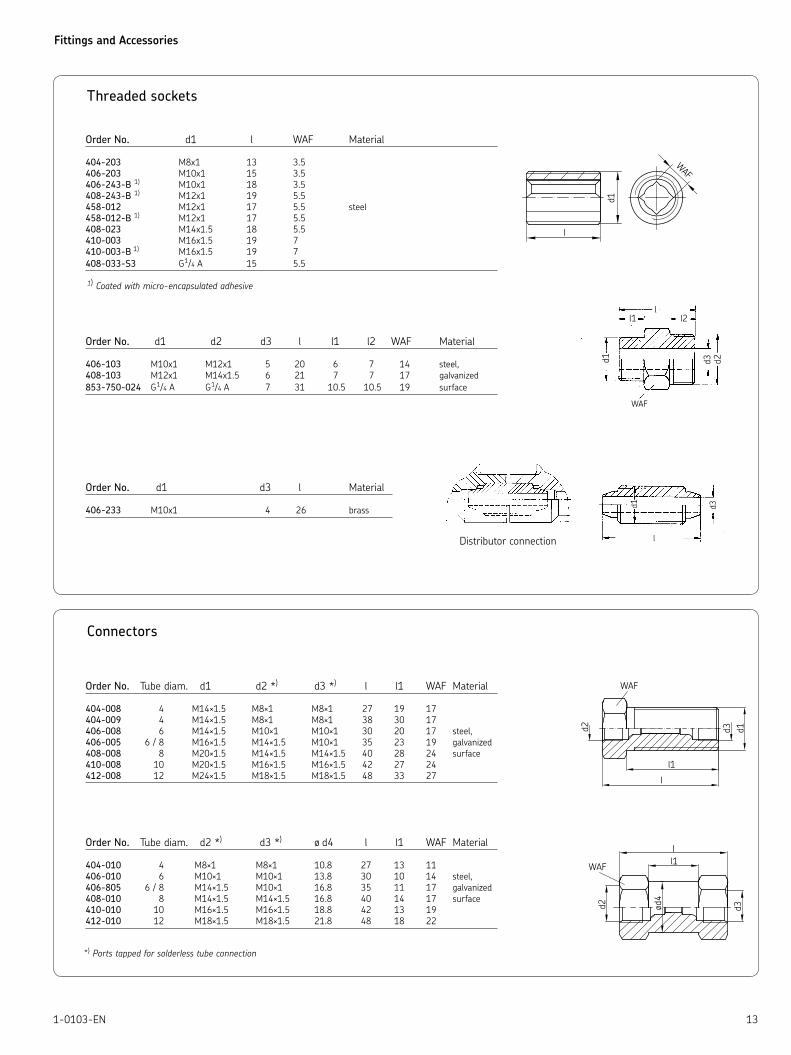
Threaded sockets
Order No. d1 l WAF Material
404-203 M8x1 13 3.5
406-203 M10x1 15 3.5
406-243-B 1) M10x1 18 3.5
408-243-B 1) M12x1 19 5.5
458-012 M12x1 17 5.5 steel
458-012-B 1) M12x1 17 5.5
408-023 M14x1.5 18 5.5
410-003 M16x1.5 19 7
410-003-B 1) M16x1.5 19 7
408-033-S3 G1/4 A 15 5.5
1) Coated with micro-encapsulated adhesive
Order No. d1 d2 d3 l l1 l2 WAF Material
406-103 M10x1 M12x1 5 20 6 7 14 steel,
408-103 M12x1 M14x1.5 6 21 7 7 17 galvanized
853-750-024 G1/4 A G1/4 A 7 31 10.5 10.5 19 surface
Order No. d1 d3 l Material
406-233 M10x1 4 26 brass
Connectors
Order No. Tube diam. d1 d2 *) d3 *) l l1 WAF Material
404-008 4 M14×1.5 M8×1 M8×1 27 19 17
404-009 4 M14×1.5 M8×1 M8×1 38 30 17
406-008 6 M14×1.5 M10×1 M10×1 30 20 17 steel,
406-005 6 / 8 M16×1.5 M14×1.5 M10×1 35 23 19 galvanized
408-008 8 M20×1.5 M14×1.5 M14×1.5 40 28 24 surface
410-008 10 M20×1.5 M16×1.5 M16×1.5 42 27 24
412-008 12 M24×1.5 M18×1.5 M18×1.5 48 33 27
Order No. Tube diam. d2 *) d3 *) ø d4 l l1 WAF Material
404-010 4 M8×1 M8×1 10.8 27 13 11
406-010 6 M10×1 M10×1 13.8 30 10 14 steel,
406-805 6 / 8 M14×1.5 M10×1 16.8 35 11 17 galvanized
408-010 8 M14×1.5 M14×1.5 16.8 40 14 17 surface
410-010 10 M16×1.5 M16×1.5 18.8 42 13 19
412-010 12 M18×1.5 M18×1.5 21.8 48 18 22
*) Ports tapped for solderless tube connection
Distributor connection
Fittings and Accessories
14 1-0103-EN
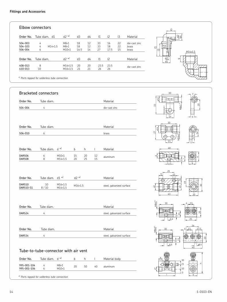
Elbow connectors
Order No. Tube diam. d1 d2 *) d3 d4 l1 l2 l3 Material
504-003 4 M8×1 18 12 33 16 22 die-cast zinc
504-103 4 M14×1.5 M8×1 18 12 33 18 22 brass
506-004 6 M10×1 16.5 14 27 17.5 15 brass
Order No. Tube diam. d2 *) d3 d4 l1 l2 Material
408-013 8 M14×1.5 20 20 23.5 23.5 die-cast zinc410-013 10 M16×1.5 21 21 26 26
*) Ports tapped for solderless tube connection
Bracketed connectors Order No. Tube diam. Material
504-004 4 die-cast zinc
Order No. Tube diam. Material
506-010 6 brass
Order No. Tube diam. d *) b h l Material
DAR506 6 M10×1 15 20 12 aluminum
DAR508 8 M14×1.5 20 25 15
Order No. Tube diam. d1 *) d2 *) Material
DAR510 10 M16×1.5 M16×1.5 steel, galvanized surfaceDAR510-S1 8 / 10 M14×1.5
Order No. Tube diam. Material
DAR524 4 steel, galvanized surface
Order No. Tube diam. Material
DAR534 4 steel, galvanized surface
Tube-to-tube-connector with air vent
Order No. Tube diam. d *) b h l Material body
995-001-104 4 M8×1 20 50 40 aluminum995-001-106 6 M10×1
*) Ports tapped for solderless tube connection
Fittings and Accessories
151-0103-EN
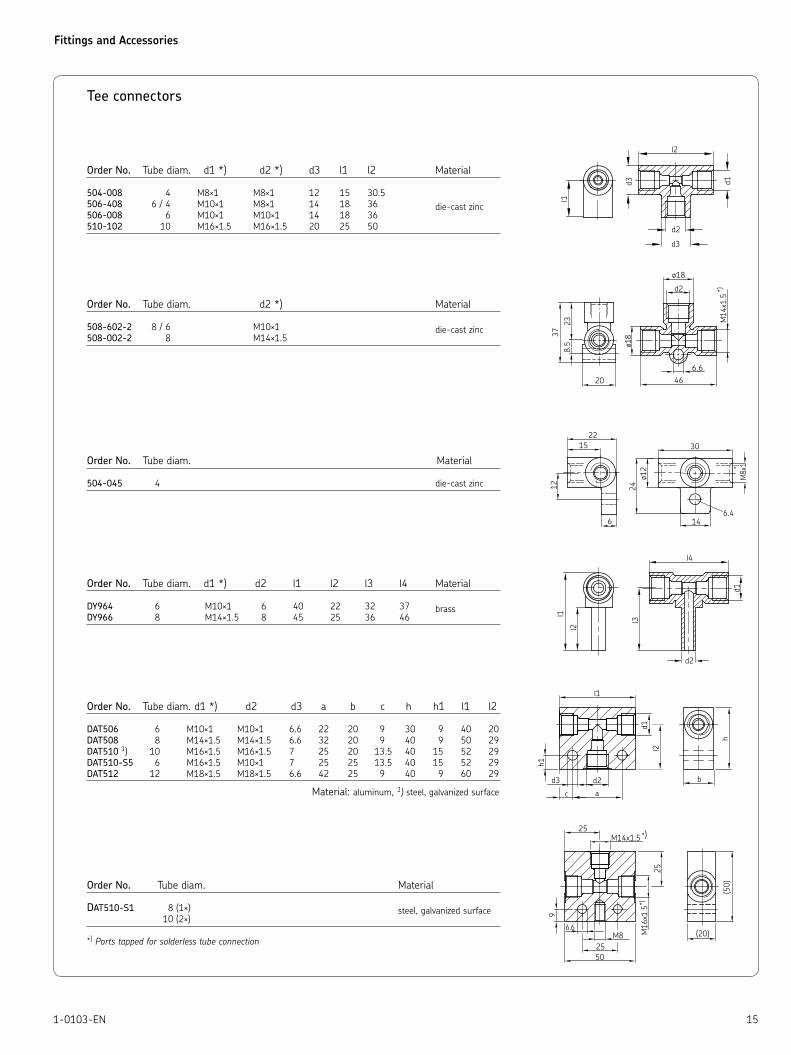
Tee connectors
Order No. Tube diam. d1 *) d2 *) d3 l1 l2 Material
504-008 4 M8×1 M8×1 12 15 30.5
506-408 6 / 4 M10×1 M8×1 14 18 36 die-cast zinc506-008 6 M10×1 M10×1 14 18 36
510-102 10 M16×1.5 M16×1.5 20 25 50
Order No. Tube diam. d2 *) Material
508-602-2 8 / 6 M10×1 die-cast zinc
508-002-2 8 M14×1.5
Order No. Tube diam. Material
504-045 4 die-cast zinc
Order No. Tube diam. d1 *) d2 l1 l2 l3 l4 Material
DY964 6 M10×1 6 40 22 32 37 brassDY966 8 M14×1.5 8 45 25 36 46
Order No. Tube diam. d1 *) d2 d3 a b c h h1 l1 l2
DAT506 6 M10×1 M10×1 6.6 22 20 9 30 9 40 20
DAT508 8 M14×1.5 M14×1.5 6.6 32 20 9 40 9 50 29
DAT510 1) 10 M16×1.5 M16×1.5 7 25 20 13.5 40 15 52 29
DAT510-S5 6 M16×1.5 M10×1 7 25 25 13.5 40 15 52 29
DAT512 12 M18×1.5 M18×1.5 6.6 42 25 9 40 9 60 29
Material: aluminum, 1) steel, galvanized surface
Order No. Tube diam. Material
DAT510-S1 8 (1×) steel, galvanized surface 10 (2×)
*) Ports tapped for solderless tube connection

Fittings and Accessories
16 1-0103-EN
Cross joints
Order No Tube diam. d1 *) a b h l1 l2 Material
DAK504-S1 4 / 6 M10×1 / M8×1 22 20 40 40 20
DAK506 6 M10×1 22 20 40 40 20
DAK508 8 M14×1.5 32 20 50 50 25 aluminum
DAK510 10 M16×1.5 25 20 56 50 28
DAK512 12 M18×1.5 42 25 60 60 30
Order No. Tube diam. d1 *) Material
DAK510-S1 10 M16×1.5 steel, galvanized surface
*) Ports tapped for solderless tube connection
Distributor manifold
Number Main tube portOrder No. of port tube diam. d1 *) d2 d3 l l1 h h1 b t
321-661 1 6 M10×1 M10×1 – 41 – 20 11 18 –
322-541 2 4 M8×1 2× M8×1 – 49 – 17 10.5 13 13
322-561 2 6 M10×1 2× M8×1 – 52 – 17 10.5 13 13
322-581 2 8 M14×1.5 2× M8×1 – 61 – 20 11 18 13
322-661 2 6 M10×1 2× M10×1 – 58 – 20 11 18 17
322-661-S1 2 8 M14×1.5 2× M10×1 – 72 – 20 11 18 22
323-541 4 M8×1 3× M8×1 – 62 – 17 10.5 13 13
323-561 6 M10×1 3× M8×1 – 65 – 17 10.5 13 13
323-581 3 8 M14×1.5 3× M8×1 – 74 – 20 11 18 13
323-661 6 M10×1 3× M10×1 – 75 – 20 11 18 17
323-661-S1 8 M14×1.5 3× M10×1 – 94 – 20 11 18 22
324-561 4 6 M10×1 4× M8×1 – 78 – 17 10.5 13 13
324-581 4 8 M14×1.5 4× M8×1 – 87 – 20 11 18 13
324-761 4 6 M10×1 4× M10×1 – 92 34 20 11 18 17
324-861 4 6 M10×1 2× M10×1 2× M10×1 58 – 20 11 18 17
325-565 5 6 M10×1 5× M8×1 – 91 – 17 10.5 13 13
325-861 5 6 M10×1 5× M10×1 – 109 51 20 11 18 17
326-562 6 6 M10×1 6× M8×1 – 104 52 20 11 18 13
326-581 6 8 M14×1.5 6× M8×1 – 113 39 20 11 18 13
326-661 6 6 M10×1 6× M10×1 – 126 68 20 11 18 17
326-663 6 6 M10×1 3× M10×1 3× M10×1 75 17 20 11 18 17
327-564 7 6 M10×1 7× M8×1 – 117 39 20 11 18 13
327-761 7 6 M10×1 7× M10×1 – 143 85 20 11 18 17
328-561 8 6 M10×1 8× M8×1 – 130 52 17 10.5 13 13
328-581 8 8 M14×1.5 8× M8×1 – 139 65 20 11 18 13
328-761 8 6 M10×1 8× M10×1 – 160 102 20 11 18 17
328-861 8 6 M10×1 4× M10×1 4× M10×1 92 34 20 11 18 17
329-761 9 6 M10×1 9× M10×1 – 177 119 20 11 18 17
329-561 10 6 M10×1 10× M8×1 – 156 78 17 10.5 13 13
330-581-S1 10 8 M14×1.5 10× M8×1 – 201 85 20 11 18 17
330-761 10 10× M10×1 – 194 136
330-861 10 5× M10×1 5× M10×1 109 51
331-761 11 11× M10×1 – 211 153
332-761 12 12× M10×1 – 228 170
332-861 12 6× M10×1 6× M10×1 126 68
334-861 14 6 M10×1 7× M10×1 7× M10×1 143 85 20 11 18 17
336-861 16 8× M10×1 8× M10×1 160 102
338-861 18 9× M10×1 9× M10×1 177 119
340-861 20 10× M10×1 10× M10×1 194 136
342-861 22 11× M10×1 11× M10×1 211 153
344-861 24 12× M10×1 12× M10×1 228 170
*) Ports tapped for solderless tube connection Material: aluminum alloy
Fittings and Accessories
171-0103-EN
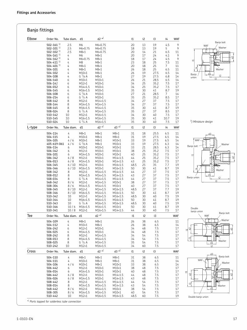
Banjo fittings
Elbow Order No. Tube diam. d1 d2 *) l1 l2 l3 l4 WAF
502-161 1) 2.5 M6 M6×0.75 20 13 19 4.5 9
502-101 1) 2.5 M6×0.75 M6×0.75 18 13 19 5 9
502-102 1) 2.5 M8×1 M6×0.75 20 14 21 6.5 11
504-161 1) 4 M6 M8×1 20 17 24 4.1 9
504-162 1) 4 M6×0.75 M8×1 18 17 24 4.5 9
504-411 1) 4 M8 M8×1 23 18 25 7.5 11
504-401 1) 4 M8×1 M8×1 20 18 25 7 11
504-101 4 M8×1 M8×1 26 18 25 6.5 11
504-102 4 M10×1 M8×1 26 19 27.5 6.5 14
504-108 4 G 1/8 A M8×1 27 19 27.5 6.8 14
506-140 6 M10×1 M10×1 26 21 28.5 6.5 14
506-142 6 M12×1 M10×1 34 25 35.2 7.5 17
506-012 6 M14×1.5 M10×1 34 25 35.2 7.5 17
506-145 6 M16×1.5 M10×1 35 30 41 8.7 19
506-108 6 G 1/8 A M10×1 27 21 28.5 7 14
506-214 6 G 1/4 A M10×1 35 25 35.2 8.5 17
508-142 8 M12×1 M14×1.5 34 27 37 7.5 17
508-144 8 M14×1.5 M14×1.5 34 27 37 7.5 17
508-145 8 M16×1.5 M14×1.5 35 30 41 8.7 19
508-024 8 G 1/4 A M14×1.5 35 27 37 8.5 17
510-142 10 M12×1 M16×1.5 34 30 40 7.5 17
510-145 10 M16×1.5 M16×1.5 35 30 41 10.7 19
510-024 10 G 1/4 A M16×1.5 35 30 40 7.5 17
L-type Order No. Tube diam. d1 d2 *) d3 *
) l1 l2 l3 l4 WAF
504-114 4 M8×1 M8×1 M8×1 31 18 25.5 6.5 11
504-115 4 M10×1 M8×1 M8×1 31 19 27.5 6.5 14
504-105 4 / 6 M10×1 M8×1 M10×1 33 19 27.5 6.5 14
405-619-061 4 / 6 G 1/8 A M8×1 M10×1 33 19 27.5 6.3 14
506-114 6 M10×1 M10×1 M10×1 33 21 28.5 6.3 14
506-342 6 M12×1 M10×1 M10×1 38 25 35.2 7.5 17
506-101 6 M14×1.5 M10×1 M10×1 40 25 35.2 7.5 17
586-342 6 / 8 M12×1 M10×1 M14×1.5 44 25 35.2 7.5 17
506-013 6 / 8 M14×1.5 M10×1 M14×1.5 43 25 35.2 7.5 17
506-345 6 / 10 M12×1 M10×1 M16×1.5 48.5 25 35 7.7 19
506-346 6 / 10 M16×1.5 M10×1 M16×1.5 50 30 41 8.7 19
508-342 8 M12×1 M14×1.5 M14×1.5 44 27 37 7.5 17
508-012 8 M14×1.5 M14×1.5 M14×1.5 43 27 37 7.5 17
508-034 8 G 1/4 A M14×1.5 M14×1.5 44 27 37 7.5 17
568-342 8 / 6 M12×1 M14×1.5 M10×1 38 27 37 7.5 17
508-304 8 / 6 M14×1.5 M14×1.5 M10×1 40 27 37 7.5 17
508-345 8 / 10 M12×1 M14×1.5 M16×1.5 48.5 27 37 7.7 19
508-346 8 / 10 M16×1.5 M14×1.5 M16×1.5 50 30 41 8.7 19
510-342 10 M12×1 M16×1.5 M16×1.5 48.5 30 40 7.5 19
510-344 10 M16×1.5 M16×1.5 M16×1.5 50 30 41 8.7 19
510-343 10 G 1/4 A M16×1.5 M16×1.5 48.5 30 40 7.5 19
510-346 10 / 6 M16×1.5 M16×1.5 M10×1 50 30 41 8.7 19
510-341 10 / 8 M12×1 M16×1.5 M14×1.5 44 30 40 7.5 17
Tee Order No. Tube diam. d1 d2 *) l1 l2 l3 WAF
504-109 4 M8×1 M8×1 26 38 6.5 11
504-112 4 M10×1 M8×1 26 38 6.5 14
506-242 6 M12×1 M10×1 34 48 7.5 17
506-025 6 M14×1.5 M10×1 34 48 7.5 17
508-242 8 M12×1 M14×1.5 34 54 7.5 17
508-013 8 M14×1.5 M14×1.5 34 54 7.5 17
508-025 8 G 1/4 A M14×1.5 35 54 7.5 17
510-242 10 M12×1 M16×1.5 34 60 7.5 17
Cross Order No. Tube diam. d1 d2 *) d3 *
) l1 l2 l3 WAF
504-110 4 M8×1 M8×1 M8×1 31 38 6.5 11
504-111 4 M10×1 M8×1 M8×1 31 38 6.5 14
504-106 4 / 6 M10×1 M8×1 M10×1 33 38 6.5 14
506-442 6 M12×1 M10×1 M10×1 38 48 7.5 17
506-014 6 M14×1.5 M10×1 M10×1 40 48 7.5 17
586-442 6 / 8 M12×1 M10×1 M14×1.5 44 48 7.5 17
506-026 6 / 8 M14×1.5 M10×1 M14×1.5 43 48 7.5 17
508-442 8 M12×1 M14×1.5 M14×1.5 44 54 7.5 17
508-014 8 M14×1.5 M14×1.5 M14×1.5 43 54 7.5 17
568-442 8 / 6 M12×1 M14×1.5 M10×1 38 54 7.5 17
508-305 8 / 6 M14×1.5 M14×1.5 M10×1 40 54 7.5 17
510-442 10 M12×1 M16×1.5 M16×1.5 48.5 60 7.5 19
*) Ports tapped for solderless tube connection
Banjo bolt
Washer
Washer
Banjounion
Banjo boltWasher
Washer
Banjo union
Banjo bolt
Washer
Washer
Doublebanjo union
Banjo bolt
Washer
Washer
Double banjo union
1) Miniature design
Fittings and Accessories
18 1-0103-EN
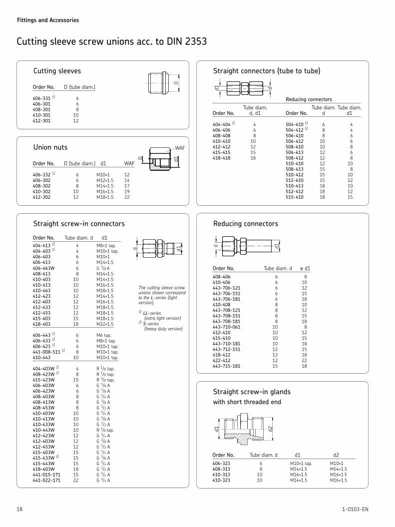
Cutting sleeve screw unions acc. to DIN 2353
Cutting sleeves
Order No. D (tube diam.)
406-331 1) 6
406-301 6
408-301 8
410-301 10
412-301 12
Union nuts
Order No. D (tube diam.) d1 WAF
406-332 1) 6 M10×1 12
406-302 6 M12×1.5 14
408-302 8 M14×1.5 17
410-302 10 M16×1.5 19
412-302 12 M18×1.5 22
Straight connectors (tube to tube)
Reducing connectors
Tube diam. Tube diam. Tube diam.Order No. d, d1 Order No. d d1
404-404 1) 4 504-410 1
) 6 4
406-406 6 504-412 1) 8 4
408-408 8 506-410 8 6
410-410 10 506-412 10 6
412-412 12 508-410 10 8
415-415 15 506-413 12 6
418-418 18 508-412 12 8
510-410 12 10
508-413 15 8
510-412 15 10
512-410 15 12
510-413 18 10
512-412 18 12
515-410 18 15
Reducing connectors
Order No. Tube diam. d ø d1
408-406 6 8
410-406 6 10
443-706-121 6 12
443-706-151 6 15
443-706-181 6 18
410-408 8 10
443-708-121 8 12
443-708-151 8 15
443-708-181 8 18
443-710-061 10 8
412-410 10 12
415-410 10 15
443-710-181 10 18
443-712-151 12 15
418-412 12 18
422-412 12 22
443-715-181 15 18
Straight screw-in connectors
Order No. Tube diam. d d1
404-413 1) 4 M8×1 tap.
404-403 1) 4 M10×1 tap.
406-403 6 M10×1
406-413 6 M14×1.5
406-463W 6 G 3/8 A
408-413 8 M14×1.5
410-403 10 M14×1.5
410-413 10 M16×1.5
410-463 10 M18×1.5
412-423 12 M14×1.5
412-403 12 M16×1.5
412-433 12 M18×1.5
412-453 12 M18×1.5
415-403 15 M18×1.5
418-403 18 M22×1.5
406-443 1) 6 M6 tap.
406-433 1) 6 M8×1 tap.
406-423 1) 6 M10×1 tap.
441-008-511 1) 8 M10×1 tap.
410-443 10 M10×1 tap.
404-403W 1) 4 R 1/8 tap.
408-423W 1) 8 R 1/8 tap.
415-423W 15 R 3/8 tap.
406-403W 6 G 1/8 A
406-423W 6 G 1/8 A
408-403W 8 G 1/4 A
408-413W 8 G 3/8 A
408-453W 8 G 1/2 A
410-403W 10 G 1/4 A
410-413W 10 G 3/8 A
410-433W 10 G 1/2 A
410-443W 10 R 1/8 tap.
412-423W 12 G 1/4 A
412-403W 12 G 3/8 A
412-453W 12 G 1/2 A
415-403W 15 G 1/4 A
415-433W 2) 15 G 3/8 A
415-443W 15 G 3/4 A
418-403W 18 G 1/2 A
441-015-171 15 G 3/4 A
441-022-171 22 G 3/4 A
The cutting sleeve screw unions shown correspond to the L-series (light version).
1) LL-series
(extra light version)2)
S-series (heavy duty version)
Straight screw-in glands
with short threaded end
Order No. Tube diam. d d1 d2
406-323 6 M10×1 tap. M10×1
408-313 8 M14×1.5 M14×1.5
410-313 10 M16×1.5 M16×1.5
410-323 10 M14×1.5 M16×1.5
Fittings and Accessories
191-0103-EN
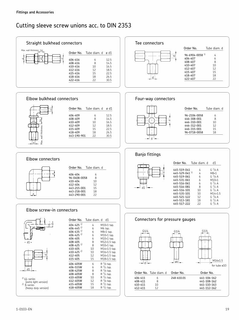
Cutting sleeve screw unions acc. to DIN 2353
Elbow connectors
Order No. Tube diam. d
406-404 6
96-0408-0058 8
410-404 10
412-404 12
443-215-001 15
443-218-001 18
443-290-001 22
Elbow bulkhead connectors
Order No. Tube diam. d ø d1
406-409 6 12.5
408-409 8 14.5
410-409 10 16.5
412-409 12 18.5
415-409 15 22.5
418-409 18 26.5
443-190-901 22 30.5
Max.
wall
thic
kness
Banjo fittings
Order No. Tube diam. d d1
445-519-041 4 G 1/8 A
445-529-041 1) 4 M8×1
445-519-061 6 G 1/8 A
445-531-061 6 M10×1
445-516-061 6 G 1/4 A
445-516-081 8 G 1/4 A
445-516-101 10 G 1/4 A
445-535-101 10 M14×1.5
445-521-122 12 G 3/8 A
445-513-181 18 G 1/2 A
445-517-222 22 G 3/4 A
Tee connectors Order No. Tube diam. d
96-6904-0058 1) 4
406-407 6
408-407 8
410-407 10
412-407 12
415-407 15
418-407 18
422-407 22
Four-way connectors
Order No. Tube diam. d
96-2106-0058 6
446-308-001 8
446-310-001 10
446-312-001 12
446-315-001 15
96-0718-0058 18
Elbow screw-in connectors
Order No. Tube diam. d d1
404-425 1) 4 M10×1 tap.
406-445 1) 6 M6 tap.
406-435 1) 6 M8×1 tap.
406-425 1) 6 M10×1 tap.
406-405 6 M10×1 tap.
408-405 8 M12×1.5 tap.
408-425 1) 8 M10×1 tap.
410-405 10 M14×1.5 tap.
410-425 2) 10 M16×1.5 tap.
412-405 12 M16×1.5 tap.
415-405 15 M18×1.5 tap.
406-405W 6 R 1/8 tap.
406-515W 6 R 1/4 tap.
408-425W 8 R 1/8 tap.
408-405W 8 R 1/4 tap.
410-405W 10 R 1/4 tap.
412-405W 12 R 3/8 tap.
415-405W 15 R 1/2 tap.
418-405W 18 R 1/2 tap.
1) LL-series(extra light version)
2) S-series (heavy duty version)
Connectors for pressure gauges
Order No. Tube diam. d Order No. Order No.
406-411 6 248-610.01 441-106-162
408-411 8 441-108-162
410-411 10 441-110-163
412-411 12 441-112-162
Straight bulkhead connectors
Order No. Tube diam. d ø d1
406-416 6 12.5
408-416 8 14.5
410-416 10 16.5
412-416 12 18.5
415-416 15 22.5
418-416 18 26.5
422-416 22 30.5

Fittings and Accessories
20 1-0103-EN
Cutting-sleeve screw unions with Eolastic washer and EO2 function nut
Straight screw-in connectors
with Eolastic washer and EO2 function nut
Order No. Tube diam. d d1
471-004-191 1) 4 G 1/8 A
471-004-311 1) M10×1
471-006-192 G 1/8 A
471-006-161 6 G 1/4 A
471-006-311 M10×1
471-006-351 M14×1.5
471-008-161 G 1/4 A
471-008-211 8 G 3/8 A
471-008-351 M14×1.5
471-008-391 M18×1.5
471-010-161 G 1/4 A
471-010-211 G 3/8 A
471-010-312 10 M10×1
471-010-351 M14×1.5
471-010-391 M18×1.5
471-012-161 G 1/4 A
471-012-211 12 G 3/8 A
471-012-391 M18×1.5
471-015-131 15 G 1/2 A
1) LL-series (extra light version)
Straight bulkhead connectors
with EO2 function nut
Order No. Tube diam. d d1
474-606-331 6 12.5
474-608-351 8 14.5
474-610-351 10 16.5
474-612-391 12 18.5
474-615-431 15 22.5
474-618-441 18 26.5
Max. operating pressure 315 bars
Straight connectors (tube to tube)
with EO2 function nut
Order No. Tube diam. d, d1
474-506-061 6
474-508-081 8
474-510-101 10
474-512-121 12
474-515-151 15
474-518-181 18
Connectors for pressure gauges
with EO2 function nut
Order No. Tube diam. d
441-106-163 6
471-108-163 8
471-110-163 10
471-112-163 12
Tee connectors
with EO2 function nut
Order No. Tube diam. d
476-006-001 6
476-008-001 8
476-010-001 10
476-012-001 12
476-015-001 15
EOLASTIC washer

Fittings and Accessories
211-0103-EN
Reducing connectors
with EO2 function nut
Order No. Tube diam. d d1
473-806-351 6 M14×1.5
473-806-391 6 M20×1.5
473-808-371 8 M16×1.5
473-808-392 8
473-810-391 10 M18×1.5
473-810-371 10
Cutting-sleeve screw unions with Eolastic washer and EO2 function nut
Screw plugs
Order No. d1
466-411-001 G 1 A
466-413-001 G 1/2 A
466-416-001 G 1/4 A
466-418-001 G 3/4 A
466-419-001 G 1/8 A
466-431-001 M10×1
466-435-003 M14×1.5
466-439-001 M18×1.5
Vent plug
Fig. 1 Fig. 2
Order No. d1 Figure
466-431-006 M10×1 1
466-431-005 M10×1 2
466-431-009 G 1/8 2
Cone plug
Order No. Tube diam. d
460-706-001 6
460-708-001 8
460-710-001 10
460-712-001 12
Fittings and Accessories
22 1-0103-EN
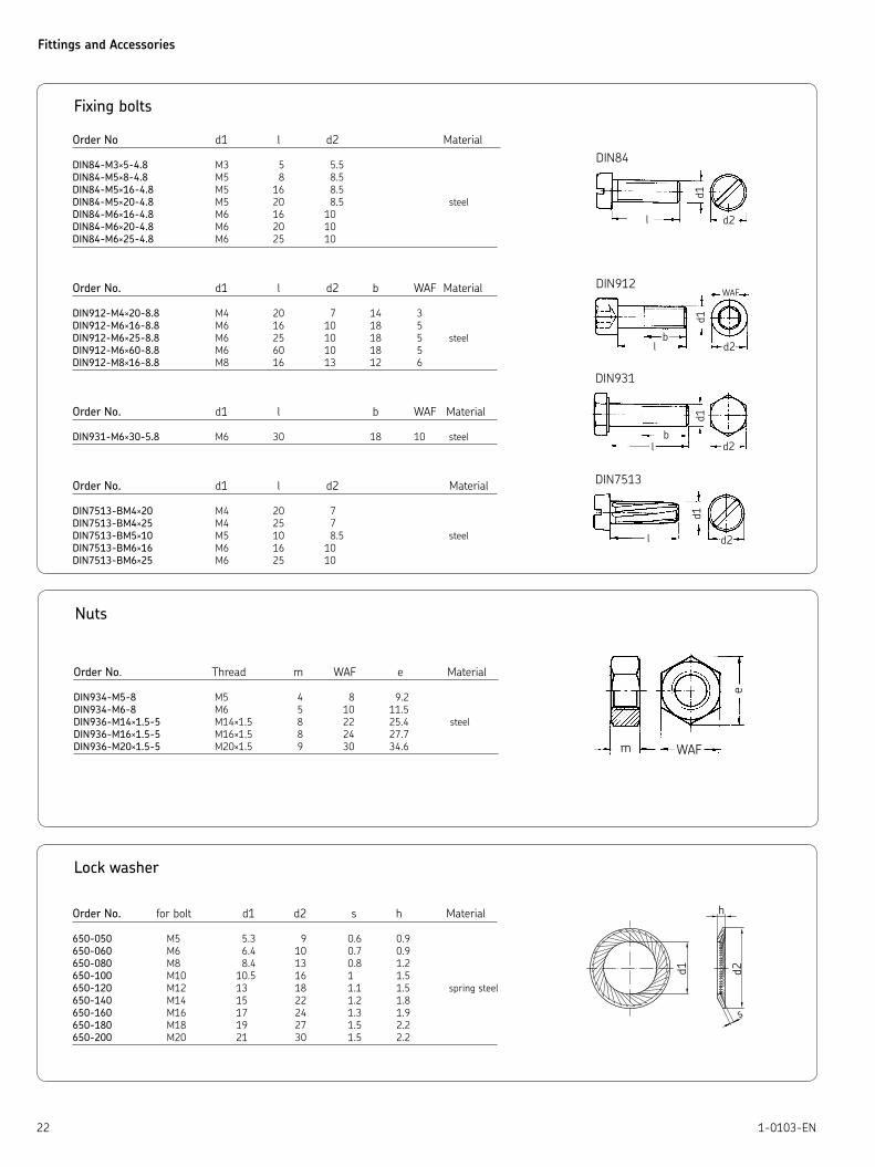
Fixing bolts
Order No d1 l d2 Material
DIN84-M3×5-4.8 M3 5 5.5
DIN84-M5×8-4.8 M5 8 8.5
DIN84-M5×16-4.8 M5 16 8.5
DIN84-M5×20-4.8 M5 20 8.5 steel
DIN84-M6×16-4.8 M6 16 10
DIN84-M6×20-4.8 M6 20 10
DIN84-M6×25-4.8 M6 25 10
Order No. d1 l d2 b WAF Material
DIN912-M4×20-8.8 M4 20 7 14 3
DIN912-M6×16-8.8 M6 16 10 18 5
DIN912-M6×25-8.8 M6 25 10 18 5 steel
DIN912-M6×60-8.8 M6 60 10 18 5
DIN912-M8×16-8.8 M8 16 13 12 6
Order No. d1 l b WAF Material
DIN931-M6×30-5.8 M6 30 18 10 steel
Order No. d1 l d2 Material
DIN7513-BM4×20 M4 20 7
DIN7513-BM4×25 M4 25 7
DIN7513-BM5×10 M5 10 8.5 steel
DIN7513-BM6×16 M6 16 10
DIN7513-BM6×25 M6 25 10
Nuts
Order No. Thread m WAF e Material
DIN934-M5-8 M5 4 8 9.2
DIN934-M6-8 M6 5 10 11.5
DIN936-M14×1.5-5 M14×1.5 8 22 25.4 steel
DIN936-M16×1.5-5 M16×1.5 8 24 27.7
DIN936-M20×1.5-5 M20×1.5 9 30 34.6
Lock washer
Order No. for bolt d1 d2 s h Material
650-050 M5 5.3 9 0.6 0.9
650-060 M6 6.4 10 0.7 0.9
650-080 M8 8.4 13 0.8 1.2
650-100 M10 10.5 16 1 1.5
650-120 M12 13 18 1.1 1.5 spring steel
650-140 M14 15 22 1.2 1.8
650-160 M16 17 24 1.3 1.9
650-180 M18 19 27 1.5 2.2
650-200 M20 21 30 1.5 2.2
Fittings and Accessories
231-0103-EN
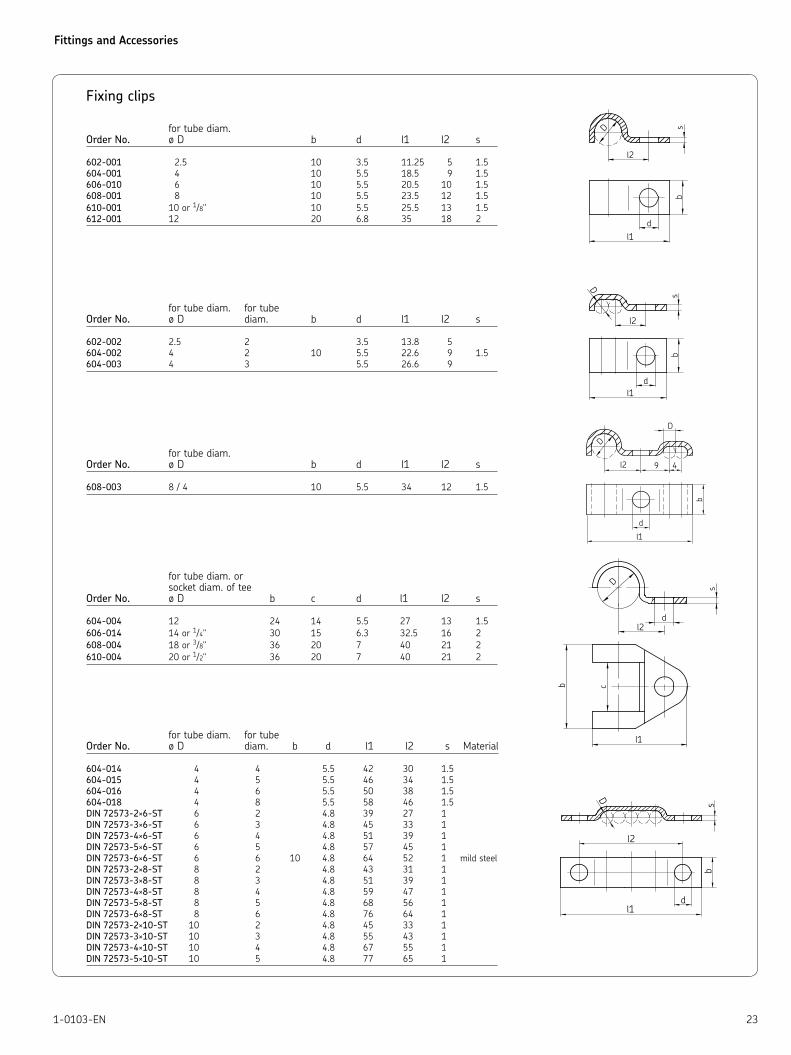
Fixing clips
for tube diam. Order No. ø D b d l1 l2 s
602-001 2.5 10 3.5 11.25 5 1.5
604-001 4 10 5.5 18.5 9 1.5
606-010 6 10 5.5 20.5 10 1.5
608-001 8 10 5.5 23.5 12 1.5
610-001 10 or 1/8" 10 5.5 25.5 13 1.5
612-001 12 20 6.8 35 18 2
for tube diam. for tubeOrder No. ø D diam. b d l1 l2 s
602-002 2.5 2 3.5 13.8 5
604-002 4 2 10 5.5 22.6 9 1.5
604-003 4 3 5.5 26.6 9
for tube diam. Order No. ø D b d l1 l2 s
608-003 8 / 4 10 5.5 34 12 1.5
for tube diam. or socket diam. of teeOrder No. ø D b c d l1 l2 s
604-004 12 24 14 5.5 27 13 1.5
606-014 14 or 1/4" 30 15 6.3 32.5 16 2
608-004 18 or 3/8" 36 20 7 40 21 2
610-004 20 or 1/2" 36 20 7 40 21 2
for tube diam. for tube Order No. ø D diam. b d l1 l2 s Material
604-014 4 4 5.5 42 30 1.5
604-015 4 5 5.5 46 34 1.5
604-016 4 6 5.5 50 38 1.5
604-018 4 8 5.5 58 46 1.5
DIN 72573-2×6-ST 6 2 4.8 39 27 1
DIN 72573-3×6-ST 6 3 4.8 45 33 1
DIN 72573-4×6-ST 6 4 4.8 51 39 1
DIN 72573-5×6-ST 6 5 4.8 57 45 1
DIN 72573-6×6-ST 6 6 10 4.8 64 52 1 mild steel
DIN 72573-2×8-ST 8 2 4.8 43 31 1
DIN 72573-3×8-ST 8 3 4.8 51 39 1
DIN 72573-4×8-ST 8 4 4.8 59 47 1
DIN 72573-5×8-ST 8 5 4.8 68 56 1
DIN 72573-6×8-ST 8 6 4.8 76 64 1
DIN 72573-2×10-ST 10 2 4.8 45 33 1
DIN 72573-3×10-ST 10 3 4.8 55 43 1
DIN 72573-4×10-ST 10 4 4.8 67 55 1
DIN 72573-5×10-ST 10 5 4.8 77 65 1

Fittings and Accessories
24 1-0103-EN
Steel tubing
Minimum bending radius r Design Burst ø da s bent with bent with pressure pressureOrder No. ±0.05 ±0.03 mandrel grooved disk [bar] [bar]
WV-RO2.5×0.5 VERKU 2.5 0.5 5 – 580 1410
WV-RO4×0.7 VERZI 4 0.7 8 7 500 1220
WV-RO6×0.7 VERZI 6 0.7 25 12 320 850
WV-RO6×1 VERZI 6 1 25 12 500 1250
WV-RO8×0.7 VERZI 8 0.7 46 19 230 675
WV-RO8×1 VERZI 8 1 46 19 340 840
WV-RO10×1 VERZI 10 *) 1 76 27 270 660
*) ø da ±0.07 VERKU = copper-plated
VERZI = 25 µm galvanization yellow passivated. Length delivered 5 m. Stainless steel tubing on request.
EN10305-4, Cr6 free
Minimum bending radius r ø da s with manual with electricalOrder No. ±0.08 bending device 1) bending device
982-120-040 4 1 – 10
982-120-060 6 1 16 9
982-120-080 8 1 22 12
982-120-100 10 1 27 15
982-120-120 12 1.5 29 18
982-120-150 15 1.5 – 22.5
982-120-180 18 1.5 – 36
Seamless cold-drawn tube for hydraulic and delivery lines according to EN10305-4
1) Tube bending device, order No. 248-803.20
Material properties:
– galvanic zinc coating (blue-white) on the outside
– thick-film passivated
– deposit thickness 9-12 μm
– Cr6 free
Fittings and Accessories
251-0103-EN
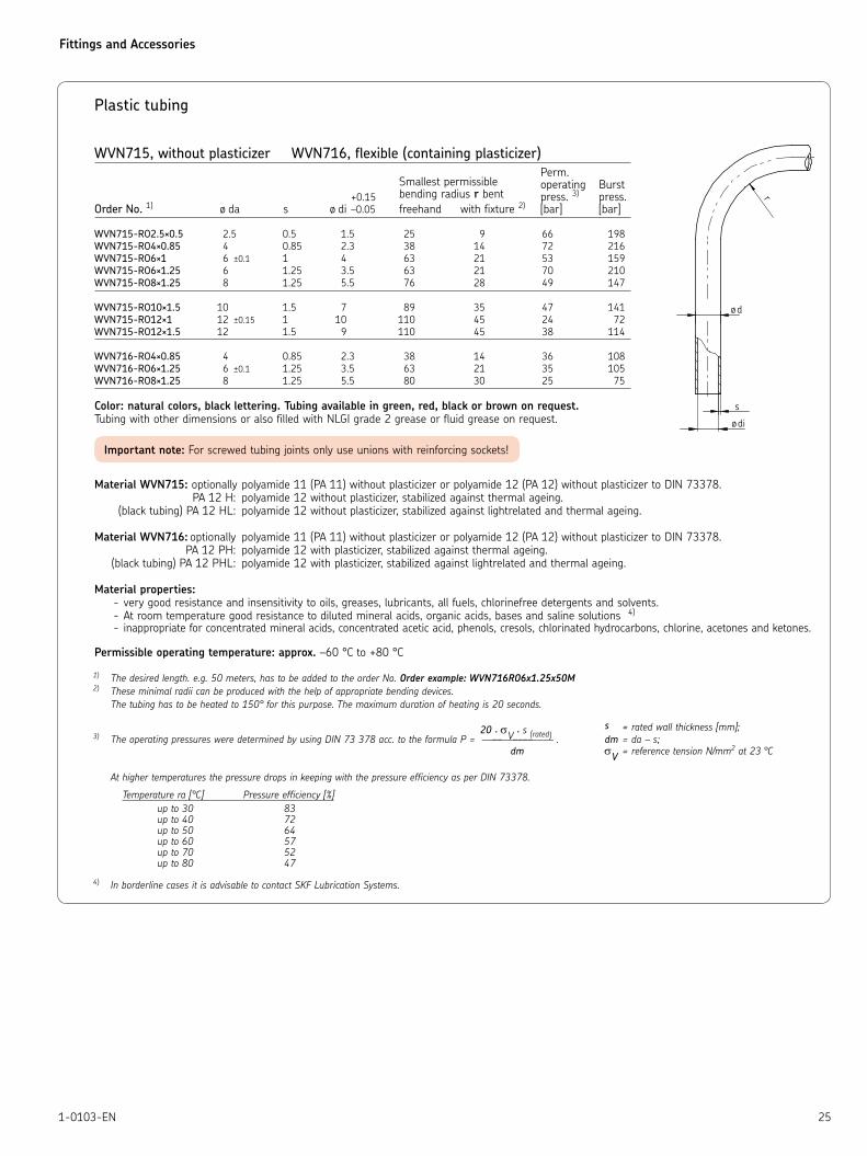
Plastic tubing
WVN715, without plasticizer WVN716, flexible (containing plasticizer)
Perm. Smallest permissible operating Burst +0.15 bending radius r bent press. 3) press.Order No. 1) ø da s ø di –0.05 freehand with fixture 2) [bar] [bar]
WVN715-RO2.5×0.5 2.5 0.5 1.5 25 9 66 198
WVN715-RO4×0.85 4 0.85 2.3 38 14 72 216
WVN715-RO6×1 6 ±0.1 1 4 63 21 53 159
WVN715-RO6×1.25 6 1.25 3.5 63 21 70 210
WVN715-RO8×1.25 8 1.25 5.5 76 28 49 147
WVN715-RO10×1.5 10 1.5 7 89 35 47 141
WVN715-RO12×1 12 ±0.15 1 10 110 45 24 72
WVN715-RO12×1.5 12 1.5 9 110 45 38 114
WVN716-RO4×0.85 4 0.85 2.3 38 14 36 108
WVN716-RO6×1.25 6 ±0.1 1.25 3.5 63 21 35 105
WVN716-RO8×1.25 8 1.25 5.5 80 30 25 75
Color: natural colors, black lettering. Tubing available in green, red, black or brown on request.
Tubing with other dimensions or also filled with NLGI grade 2 grease or fluid grease on request.
Material WVN715: optionally polyamide 11 (PA 11) without plasticizer or polyamide 12 (PA 12) without plasticizer to DIN 73378.
PA 12 H: polyamide 12 without plasticizer, stabilized against thermal ageing.
(black tubing) PA 12 HL: polyamide 12 without plasticizer, stabilized against lightrelated and thermal ageing.
Material WVN716: optionally polyamide 11 (PA 11) without plasticizer or polyamide 12 (PA 12) without plasticizer to DIN 73378.
PA 12 PH: polyamide 12 with plasticizer, stabilized against thermal ageing.
(black tubing) PA 12 PHL: polyamide 12 with plasticizer, stabilized against lightrelated and thermal ageing.
Material properties:
very good resistance and insensitivity to oils, greases, lubricants, all fuels, chlorinefree detergents and solvents. -
At room temperature good resistance to diluted mineral acids, organic acids, bases and saline solutions - 4)
inappropriate for concentrated mineral acids, concentrated acetic acid, phenols, cresols, chlorinated hydrocarbons, chlorine, acetones and ketones. -
Permissible operating temperature: approx. –60 °C to +80 °C
1) The desired length. e.g. 50 meters, has to be added to the order No. Order example: WVN716RO6x1.25x50M 2) These minimal radii can be produced with the help of appropriate bending devices.
The tubing has to be heated to 150° for this purpose. The maximum duration of heating is 20 seconds.
20 · σV · s (rated) s = rated wall thickness [mm];
3) The operating pressures were determined by using DIN 73 378 acc. to the formula P = –––––––––––––– . dm = da – s;
dm σV = reference tension N/mm2 at 23 °C
At higher temperatures the pressure drops in keeping with the pressure efficiency as per DIN 73378.
Temperature ra [°C] Pressure efficiency [%]
up to 30 83 up to 40 72 up to 50 64 up to 60 57 up to 70 52 up to 80 47
4) In borderline cases it is advisable to contact SKF Lubrication Systems.
Important note: For screwed tubing joints only use unions with reinforcing sockets!
Fittings and Accessories
26 1-0103-EN
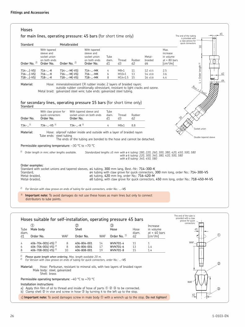
Hoses
for main lines, operating pressure: 45 bars (for short time only)
Standard Metalbraided
With tapered With tapered Max.
sleeve and sleeve and increase
socket union socket union Tube Metal- in volume
on both ends on both ends diam. Thread Rubber braided at ≈ 80 bars
Order No. 2) Order No. Order No. 2) Order No. d1 d3 d2 d4 [cm³/m]
714-...(-VS) 714-...-K 714-...-M(-VS) 714-...-MK 4 M8×1 11 12 ±0.5 2.5
716-...(-VS) 716-...-K 716-...-M(-VS) 716-...-MK 6 M10×1 13 14 ±0.8 3.6
718-...(-VS) 718-...-K 718-...-M (-VS) 718-...-MK 8 M14×1.5 15 16 ±0.8 4.4
Material: Hose: mineraloilresistant CR rubber inside; 2 layers of braided rayon; outside rubber conditionally oilresistant, resistant to light cracks and ozone. Metal braid: galvanized steel wire; tube ends: galvanized steel tubing.
for secondary lines, operating pressure 15 bars (for short time only) Standard
With claw groove for With tapered sleeve and Tube
quick connectors socket union on both ends diam. Thread Rubber
Order No. Order No. Order No. d1 d3 d2
734-...3) 734-...-VS 3) 734-...-K 3) 4 M8x1 8.8
Material: Hose: oilproof rubber inside and outside with a layer of braided rayon Tube ends: steel tubing The ends of the tubing are bonded to the hose and cannot be detached.
Permissible operating temperature: –30 °C to +70 °C
1) Order length in mm; other lengths available. Standardized lengths ±5 mm with ø 4 tubing: 180, 220, 260, 300, 380, 420, 450, 500, 580 with ø 6 tubing: 220, 300, 340, 380, 420, 500, 580 with ø 8 tubing: 340, 450, 580
Order examples:Standard with socket unions and tapered sleeves, ø4 tubing, 300 mm lang, Best.-Nr.: 714-300-KStandard, ø4 tubing with claw grove for quick connectors, 300 mm long, order No.: 714-300-VSMetal-braided, ø6 tubing, 420 mm lng, order No.: 716-420-MMetal-braided, ø8 tubing, with claw grove for quick connectors, 450 mm long, order No.: 718-450-M-VS
2) For Version with claw groove on ends of tubing for quick connectors, order No.: ...-VS
Socket union
Double-tapered sleeve
The end of the tubing is provided with
a claw groove for quick connectors
Hoses suitable for self-installation, operating pressure 45 bars
➀ ➁ ➂ IncreaseTube Male body Shell Hose Hose in volumediam. diam. at ≈ 40 barsd1 Order No. WAF Order No. WAF Order No. 1) d2 [cm³/m]
4 406-704-001(-VS) 2) 8 406-804-001 14 WVN701-4 11 1
6 406-706-001(-VS) 2) 8 406-806-001 17 WVN701-6 13 1.4
8 406-708-001(-VS) 2) 10 406-808-001 19 WVN701-8 15 1.4
1) Please quote length when ordering. Max. length available 20 m. 2) For Version with claw groove on ends of tubing for quick connectors, order No.: ...-VS
Material: Hose: Perbunan, resistant to mineral oils, with two layers of braided rayon Male body: steel, galvanized Shell: brass
Permissible operating temperature: –40 °C to +70 °C
Installation instructions
a) Apply thin film of oil to thread and inside of hose of parts ➀ ➁ ➂ to be connected.b) Clamp shell ➁ in vise and screw in hose ➂ by turning it to the left up to the stop.
The end of the tube is provided with a claw
groove for quick connectors
➀
➁
➂
3) Important note: To avoid damages do not use these hoses as main lines but only to connect
distributors to lube points.
c) Important note: To avoid damages screw in male body ➀ with a wrench up to the stop. Do not tighten!

Fittings and Accessories
271-0103-EN
High pressure hoses, operating pressure: 280 – 330 bars
Tube Hose Permissible Burst diam. diam. Length 1) operating pressure pressureOrder No. ø d1 ø d2 l+5 l1 [bar] [bar]
SLH6-180 6 10 180 22 210 840
SLH8-180 8 11.8 180 30 210 830
SLH10-180 10 14 180 30 175 690
1) Order length in mm; other lengths available.
Order example: highpressure hose SLH8, 600 mm long, order No.: SLH8-600
Material: Inner liner: PA 11/12 or PE-E Reinforcement: 1 braided layer of synthetic fibre with high tensile strength Outer cover: PA 11/12
Resistant to mineral oils.
Permissible operating temperature: –40 °C to +100 °C
High pressure hoses for self-installation, operating pressure: 325 bars / 130 bars
for main lines (connection: pump – feeder) and secondary lines (connection: feeder – lubrication point)
Designation Order No. L a b
➀ High press. hose, max. length supplied 50 m 982-750-091
High press. hose, max. length supplied 50 m 982-750-091+AF2
filled with NLGI grade 2 grease
➁ Sleeve 853-540-010
➂ Tube stud, straight 853-370-002(-VS) 1) 20
853-380-002(-VS) 1) 30
853-390-002(-VS) 1) 66
➃ Tube stud, 45° angle 853-380-004(-VS) 1)
Tube stud, 90° angle 853-380-003(-VS) 1) 2 21
853-390-003(-VS) 1) 13 47
1) Version with claw groove on ends of tubing for quick connectors, order No.: ...-VS
for main lines (connection: pump – feeder)
*) Take length of engaged thread and double it when determining the length of the hose.
Designation Order No.
➀ High press. hose, max. length supplied 100 m WVN711-10
High press. hose, max. length supplied 50 m WVN711-10+AF2
filled with NLGI grade 2 grease
➁ Sleeve 406-810-002
➂ Tube stud 406-710-002
Technical data:Hose: operating pressure 325 bars burst pressure 800 bars min. bending radius 35 mm
Material:Hose:Inner lining: unplasticized polyesterInner layer: braided synthetic fibersOuter cover: weatherproof polyurethane
Sleeve, tube stud: steel, galvanized
Permissible operating temperature:–30 °C to +70 °C
*) Take length of engaged thread and double it when determining the length of the hose.
Technical data: Hose: operating pressure 130 bars burst pressure 315 bars min. bending radius 55 mmMaterial: Hose: Inner lining: Perbunan Inner layer: diagonally woven synthetic fibers Outer cover: weatherproof neoprene
Sleeve: aluminum alloy Tube stud: steel, galvanized
Permissible operating temperature: –40 °C to +100 °C
The end of the tubing is
provided with a claw
groove for quick connectors
The end of the tubing is
provided with a claw groove
for quick connectors
Fittings and Accessories
28 1-0103-EN
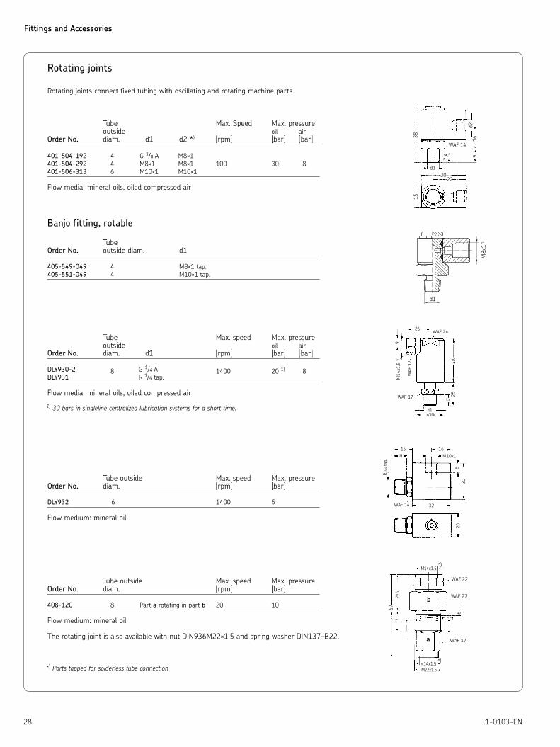
Rotating joints
Rotating joints connect fixed tubing with oscillating and rotating machine parts.
Tube Max. Speed Max. pressure outside oil air
Order No. diam. d1 d2 *) [rpm] [bar] [bar]
401-504-192 4 G 1/8 A M8×1
401-504-292 4 M8×1 M8×1 100 30 8
401-506-313 6 M10×1 M10×1
Flow media: mineral oils, oiled compressed air
Banjo fitting, rotable
TubeOrder No. outside diam. d1
405-549-049 4 M8×1 tap.
405-551-049 4 M10×1 tap.
Tube Max. speed Max. pressure outside oil air
Order No. diam. d1 [rpm] [bar] [bar]
DLY930-2 8 G 1/4 A 1400 20 1) 8DLY931 R 1/4 tap.
Flow media: mineral oils, oiled compressed air
1) 30 bars in singleline centralized lubrication systems for a short time.
Tube outside Max. speed Max. pressure Order No. diam. [rpm] [bar]
DLY932 6 1400 5
Flow medium: mineral oil
Tube outside Max. speed Max. pressure Order No. diam. [rpm] [bar]
408-120 8 Part a rotating in part b 20 10
Flow medium: mineral oil
The rotating joint is also available with nut DIN936M22×1.5 and spring washer DIN137-B22.
*) Ports tapped for solderless tube connection
Fittings and Accessories
291-0103-EN
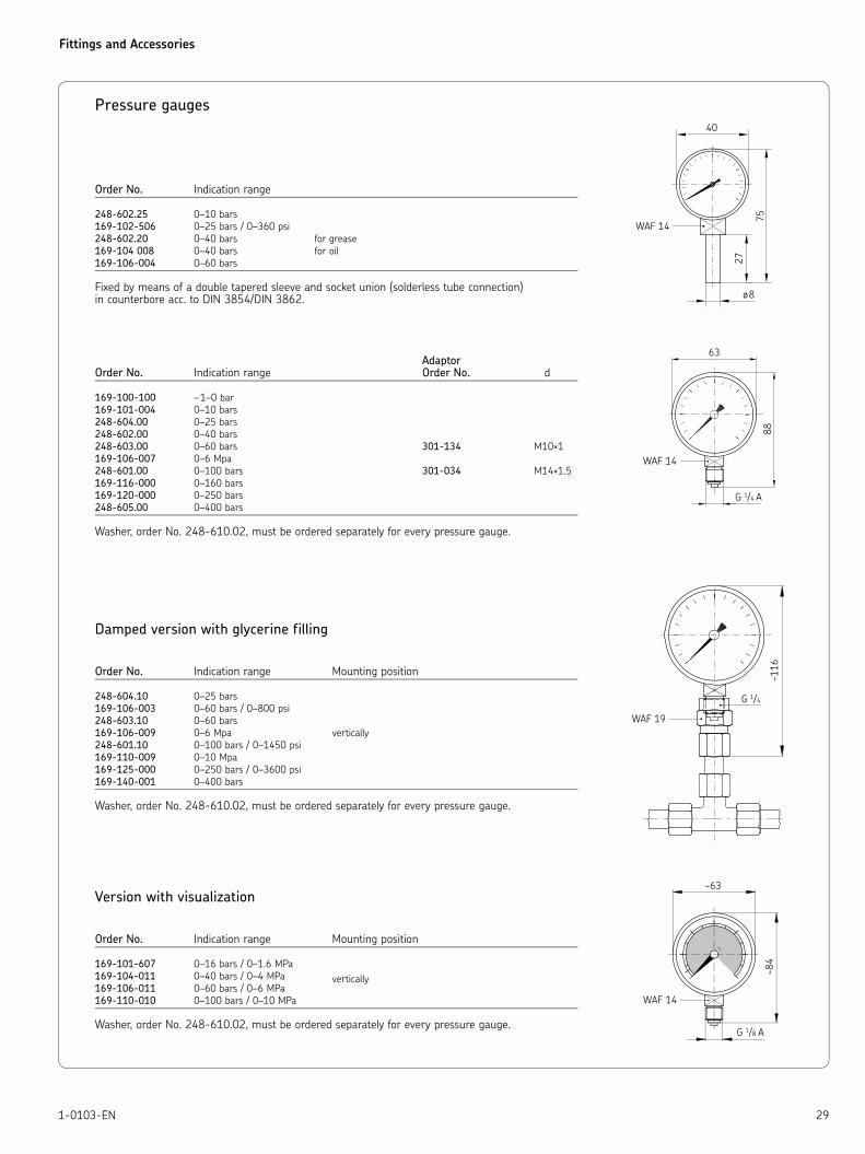
Pressure gauges
Order No. Indication range
248-602.25 0–10 bars
169-102-506 0–25 bars / 0–360 psi
248-602.20 0–40 bars for grease
169-104 008 0–40 bars for oil
169-106-004 0–60 bars
Fixed by means of a double tapered sleeve and socket union (solderless tube connection)in counterbore acc. to DIN 3854/DIN 3862.
AdaptorOrder No. Indication range Order No. d
169-100-100 – 1–0 bar
169-101-004 0–10 bars
248-604.00 0–25 bars
248-602.00 0–40 bars
248-603.00 0–60 bars 301-134 M10×1
169-106-007 0–6 Mpa
248-601.00 0–100 bars 301-034 M14×1.5
169-116-000 0–160 bars
169-120-000 0–250 bars
248-605.00 0–400 bars
Washer, order No. 248-610.02, must be ordered separately for every pressure gauge.
Damped version with glycerine filling
Order No. Indication range Mounting position
248-604.10 0–25 bars
169-106-003 0–60 bars / 0–800 psi
248-603.10 0–60 bars
169-106-009 0–6 Mpa vertically
248-601.10 0–100 bars / 0–1450 psi
169-110-009 0–10 Mpa
169-125-000 0–250 bars / 0–3600 psi
169-140-001 0–400 bars
Washer, order No. 248-610.02, must be ordered separately for every pressure gauge.
Version with visualization
Order No. Indication range Mounting position
169-101-607 0–16 bars / 0–1.6 MPa
169-104-011 0–40 bars / 0–4 MPa vertically169-106-011 0–60 bars / 0–6 MPa
169-110-010 0–100 bars / 0–10 MPa
Washer, order No. 248-610.02, must be ordered separately for every pressure gauge.

Fittings and Accessories
30 1-0103-EN
Shut-off valves
Max. pressure Max. Order No. [bar] temperature [°C] Spindleway
202-085-S 60 80 max. 3 revs.
Direction of flow optional
Max. pressure Max. Order No. [bar] temperature [°C]
161-600-036 16 90
*) Ports tapped for solderless tube connection
»
Quick-disconnect couplings
Coupling, complete
Tube FlowOrder No. diam. d1 *) l2 direction
207-168-2 6 M10×1 62 optional
207-188-2 8 M14×1.5 66,5
Outer coupling member
TubeOrder No. diam. l1
207-168.U7 6 48.5
207-188.U11 8 53
Inner coupling member
Order No. 207-168.U2
Both coupling members are shut off when disconnected!
*) Ports tapped for solderless tube connection
Coupled
Pres
sure
loss
Δp
(bar
)
Pressure loss as a function of the
flow rate based on an operating
oil viscosity of 140 mm2/s
Flow rate (l/min)
Fittings and Accessories
311-0103-EN
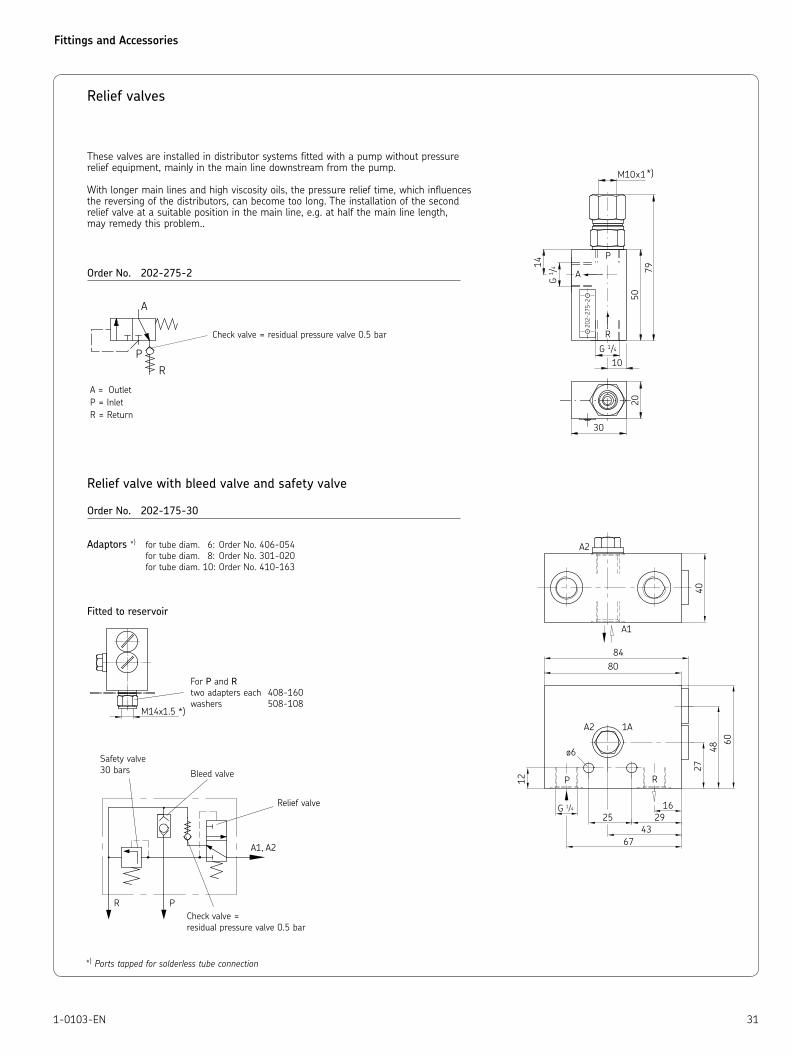
Relief valves
Order No. 202-275-2
Relief valve with bleed valve and safety valve
Order No. 202-175-30
Adaptors *) for tube diam. 6: Order No. 406-054
for tube diam. 8: Order No. 301-020
for tube diam. 10: Order No. 410-163
Fitted to reservoir
These valves are installed in distributor systems fitted with a pump without pressurerelief equipment, mainly in the main line downstream from the pump.
With longer main lines and high viscosity oils, the pressure relief time, which influences the reversing of the distributors, can become too long. The installation of the second relief valve at a suitable position in the main line, e.g. at half the main line length, may remedy this problem..
A = Outlet
P = Inlet
R = Return
Check valve = residual pressure valve 0.5 bar
For P and R
two adapters each 408-160
washers 508-108
Bleed valve
Relief valve
Safety valve
30 bars
Check valve =
residual pressure valve 0.5 bar
*) Ports tapped for solderless tube connection
Fittings and Accessories
32 1-0103-EN
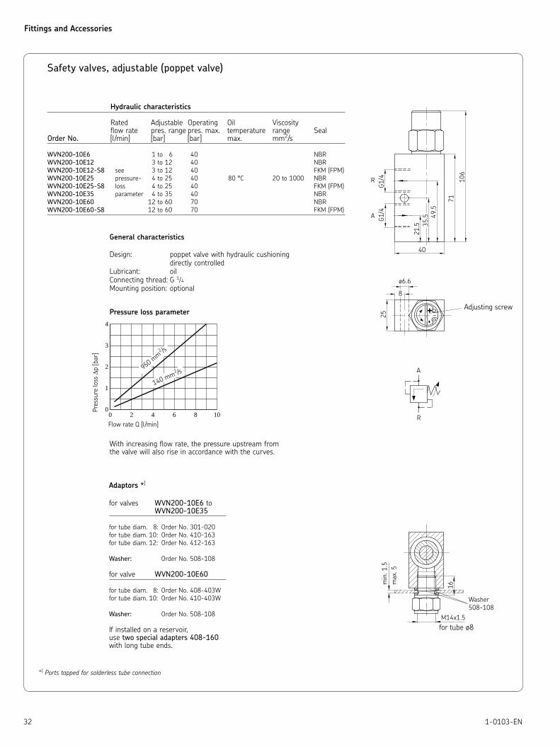
Safety valves, adjustable (poppet valve)
Hydraulic characteristics
Rated Adjustable Operating Oil Viscosity flow rate pres. range pres. max. temperature range SealOrder No. [l/min] [bar] [bar] max. mm2/s
WVN200-10E6 1 to 6 40 NBR
WVN200-10E12 3 to 12 40 NBR
WVN200-10E12-S8 see 3 to 12 40 FKM (FPM)
WVN200-10E25 pressure- 4 to 25 40 80 °C 20 to 1000 NBR
WVN200-10E25-S8 loss 4 to 25 40 FKM (FPM)
WVN200-10E35 parameter 4 to 35 40 NBR
WVN200-10E60 12 to 60 70 NBR
WVN200-10E60-S8 12 to 60 70 FKM (FPM)
General characteristics
Design: poppet valve with hydraulic cushioning
directly controlled
Lubricant: oil
Connecting thread: G 1/4
Mounting position: optional
Pressure loss parameter
With increasing flow rate, the pressure upstream from the valve will also rise in accordance with the curves.
*) Ports tapped for solderless tube connection
Adaptors *)
for valves WVN200-10E6 to WVN200-10E35
for tube diam. 8: Order No. 301-020
for tube diam. 10: Order No. 410-163
for tube diam. 12: Order No. 412-163
Washer: Order No. 508-108
for valve WVN200-10E60
for tube diam. 8: Order No. 408-403W
for tube diam. 10: Order No. 410-403W
Washer: Order No. 508-108
If installed on a reservoir,use two special adapters 408-160 with long tube ends.
0 2 4 6 8 10Flow rate Q [l/min]
Pres
sure
loss
Δp
[bar
]
4
3
2
1
0
950 mm
2 /s
140 mm2 /s
Adjusting screw
Washer
508-108
for tube ø8
Fittings and Accessories
331-0103-EN
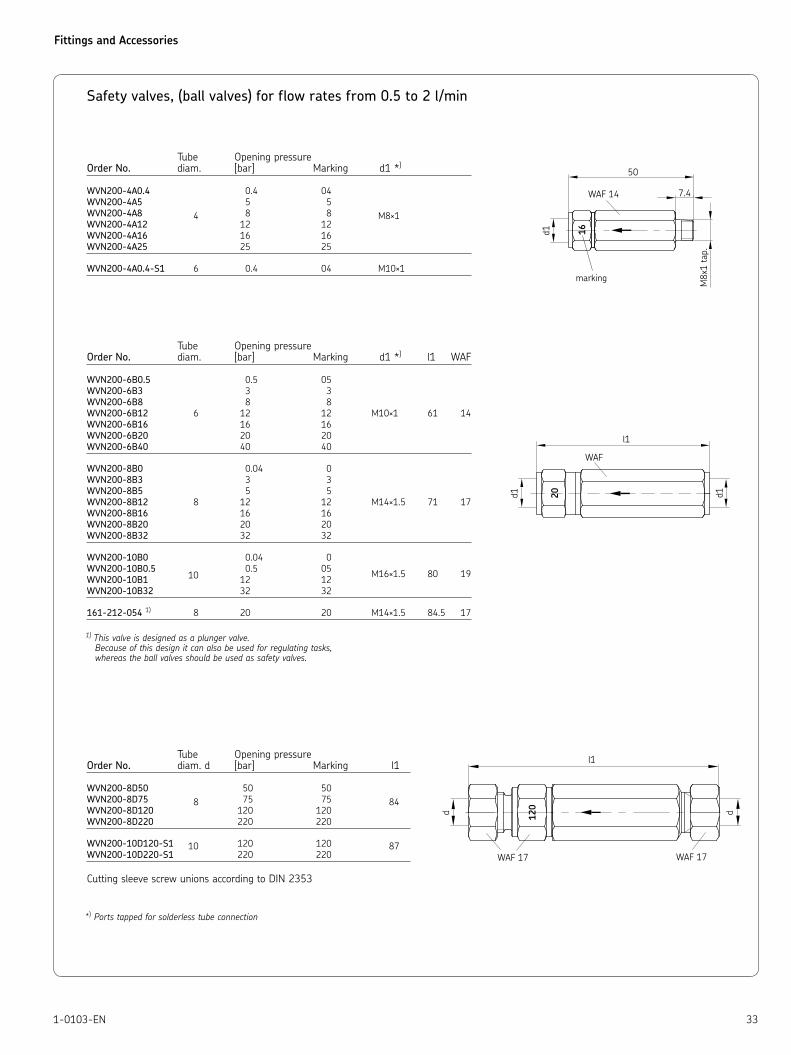
Safety valves, (ball valves) for flow rates from 0.5 to 2 l/min
Tube Opening pressureOrder No. diam. [bar] Marking d1 *)
WVN200-4A0.4 0.4 04
WVN200-4A5 5 5
WVN200-4A8 4 8 8 M8×1
WVN200-4A12 12 12
WVN200-4A16 16 16
WVN200-4A25 25 25
WVN200-4A0.4-S1 6 0.4 04 M10×1
Tube Opening pressureOrder No. diam. [bar] Marking d1 *) l1 WAF
WVN200-6B0.5 0.5 05
WVN200-6B3 3 3
WVN200-6B8 8 8
WVN200-6B12 6 12 12 M10×1 61 14
WVN200-6B16 16 16
WVN200-6B20 20 20
WVN200-6B40 40 40
WVN200-8B0 0.04 0
WVN200-8B3 3 3
WVN200-8B5 5 5
WVN200-8B12 8 12 12 M14×1.5 71 17
WVN200-8B16 16 16
WVN200-8B20 20 20
WVN200-8B32 32 32
WVN200-10B0 0.04 0
WVN200-10B0.5 10
0.5 05 M16×1.5 80 19
WVN200-10B1 12 12
WVN200-10B32 32 32
161-212-054 1) 8 20 20 M14×1.5 84.5 17
1) This valve is designed as a plunger valve. Because of this design it can also be used for regulating tasks, whereas the ball valves should be used as safety valves.
Tube Opening pressure Order No. diam. d [bar] Marking l1
WVN200-8D50 50 50
WVN200-8D75 8 75 75 84WVN200-8D120 120 120
WVN200-8D220 220 220
WVN200-10D120-S1 10 120 120 87
WVN200-10D220-S1 220 220
Cutting sleeve screw unions according to DIN 2353
*) Ports tapped for solderless tube connection
marking
Fittings and Accessories
34 1-0103-EN
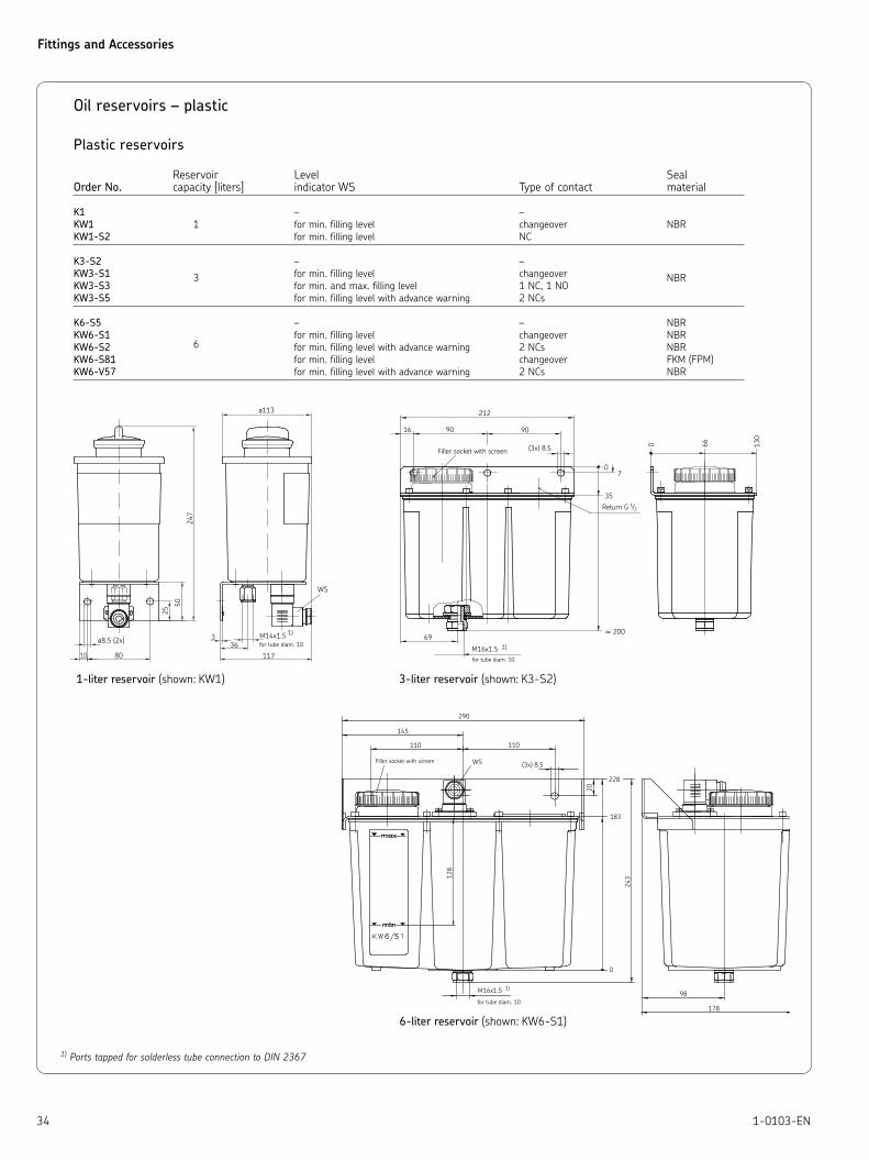
Oil reservoirs – plastic
Plastic reservoirs
Reservoir Level SealOrder No. capacity [liters] indicator WS Type of contact material
K1 – –
KW1 1 for min. filling level changeover NBR
KW1-S2 for min. filling level NC
K3-S2 – –
KW3-S1 3 for min. filling level changeover NBRKW3-S3 for min. and max. filling level 1 NC, 1 NO
KW3-S5 for min. filling level with advance warning 2 NCs
K6-S5 – – NBR
KW6-S1 for min. filling level changeover NBR
KW6-S2 6 for min. filling level with advance warning 2 NCs NBR
KW6-S81 for min. filling level changeover FKM (FPM)
KW6-V57 for min. filling level with advance warning 2 NCs NBR
1) Ports tapped for solderless tube connection to DIN 2367
≈
1-liter reservoir (shown: KW1) 3-liter reservoir (shown: K3-S2)
6-liter reservoir (shown: KW6-S1)

Fittings and Accessories
351-0103-EN
Oil reservoirs – metal
Metal reservoirs
Reservoir Level SealOrder No. capacity [liters] indicator WS Type of contact material
B3-S1 – – NBR
BW3-S9 3 for min. filling level with advance warning 2 NOs NBR
BW3-S81 for min. filling level changeover FKM (FPM)
162-210-005 for min. filling level changeover NBR
B7 – – NBR
BW7-S6 for min. and max. filling level 2 NCs NBR
BW7-S7 for min. filling level with advance warning 2 NCs NBR
BW7-S8 6 for min. filling level changeover FKM (FPM)
BW7-S11 for min. filling level with advance warning 1 NO, 1 NC NBR
BW7-S12 for min. filling level with advance warning 1 NO, 1 NC NBR
162-310-005 for min. filling level changeover NBR
Oil level gauges for metal reservoir
Reservoir Order No. capacity [liters] l l1
995-003-044 6 152 127
995-003-040 6 190 165
995-003-041 15 and 30 215 190
995-003-042 50 279 254
995-003-043 100 305 280
Type: NBR
FKM (FPM) on request
≈
≈
3-liter reservoir
6-liter reservoir (shown: BW7-S6)
Filler socket with screen
Fittings and Accessories
36 1-0103-EN
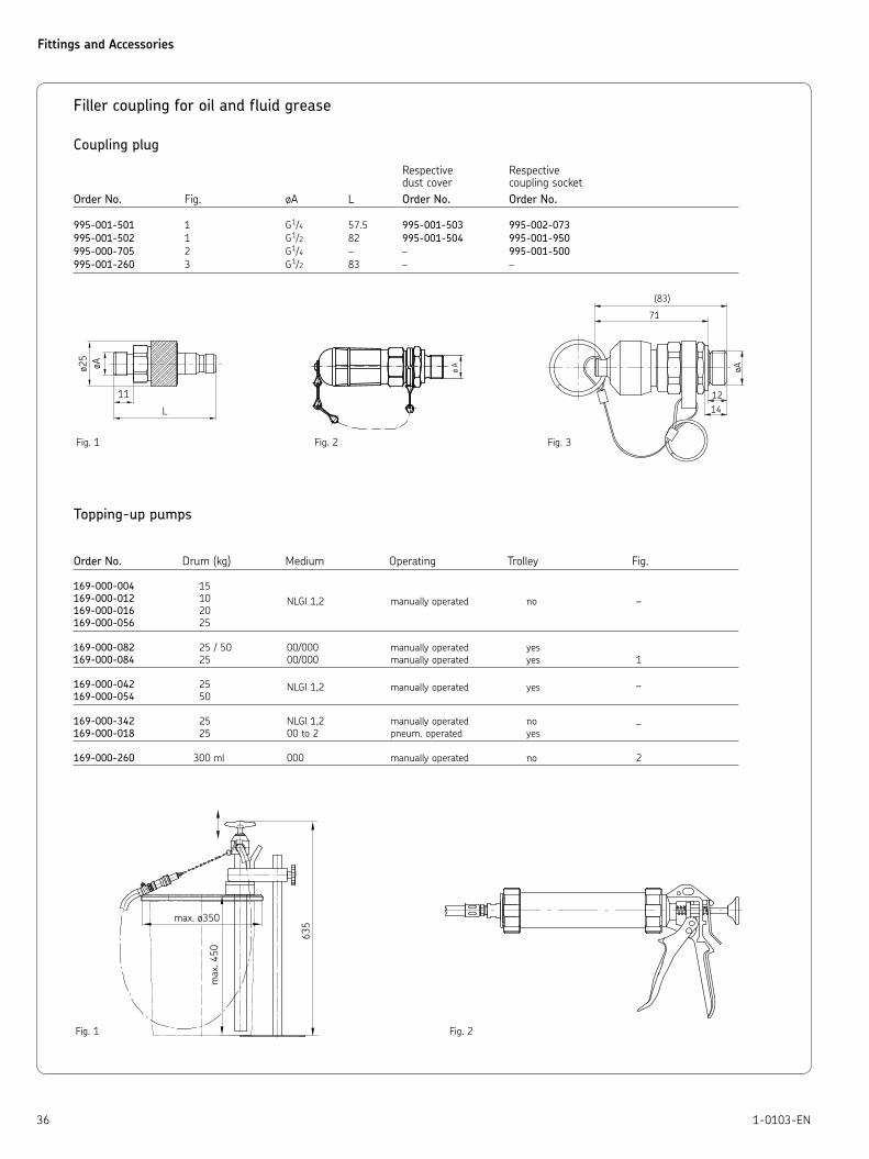
Filler coupling for oil and fluid grease
Coupling plug
Respective Respective dust cover coupling socket
Order No. Fig. øA L Order No. Order No.
995-001-501 1 G1/4 57.5 995-001-503 995-002-073
995-001-502 1 G1/2 82 995-001-504 995-001-950
995-000-705 2 G1/4 – – 995-001-500
995-001-260 3 G1/2 83 – –
Topping-up pumps
Order No. Drum (kg) Medium Operating Trolley Fig.
169-000-004 15
169-000-012 10 NLGI 1,2 manually operated no –
169-000-016 20
169-000-056 25
169-000-082 25 / 50 00/000 manually operated yes
169-000-084 25 00/000 manually operated yes 1
169-000-042 25 NLGI 1,2 manually operated yes –169-000-054 50
169-000-342 25 NLGI 1,2 manually operated no – 169-000-018 25 00 to 2 pneum. operated yes
169-000-260 300 ml 000 manually operated no 2
Fig. 1 Fig. 2 Fig. 3
Fig. 1 Fig. 2

Fittings and Accessories
371-0103-EN
Notes

Fittings and Accessories
38 1-0103-EN
Notes

This brochure was presented by:
Order No. 1-0103-ENSubject to change without notice! (07/2009)
Important product usage informationAll products from SKF may be used only for their intended purpose as described in this brochure and in any instructions. If operating instructions are supplied with the products, they must be read and followed.Not all lubricants are suitable for use in centralized lubrication systems. SKF does offer an inspection service to test customer supplied lubricant to determine if it can be used in a centralized system. SKF lubrication systems or their components are not approved for use with gases, liquefied gases, pressurized gases in solution and fluids with a vapor pressure exceeding normal atmospheric pressure (1013 mbars) by more than 0.5 bar at their maximum permissible temperature.Hazardous materials of any kind, especially the materials classified as ha-zardous by European Community Directive EC 67/548/EEC, Article 2, Par. 2, may only be used to fill SKF centralized lubrication systems and components and delivered and/or distributed with the same after consulting with and receiving written approval from SKF.
SKF Lubrication Systems Germany AG
Motzener Strasse 35/37 · 12277 Berlin · Germany
PF 970444 · 12704 Berlin · Germany
Tel. +49 (0)30 72002-0 · Fax +49 (0)30 72002-111
www.skf.com/lubrication
® SKF is a registered trademark of the SKF Group.
© SKF Group 2009The contents of this publication are the copyright of the publisher and may not be reproduced (even extracts) unless prior written permission is gran-ted. Every care has been taken to ensure the accuracy of the information contained in this publication but no liability can be accepted for any loss or damage whether direct, indirect or consequential arising out of the use of the information contained herein.
Leaflet
1-0103-1-EN Quick connectors1-9201-EN Transport of Lubricants in Centralized Lubrication Systems