first-principles tensile tests of tilt and twist grain ... tensile tests of tilt and twist grain...
TRANSCRIPT
First-Principles Tensile Tests of Tilt and Twist Grain Boundaries in Al
Ru-Zhi Wang1,2, Shingo Tanaka1 and Masanori Kohyama1,+
1Research Institute for Ubiquitous Energy Devices, National Institute of Advanced Industrial Science and Technology,Ikeda 563-8577, Japan2College of Materials Science and Engineering, Beijing University of Technology, Beijing 100124, P. R. China
In order to clarify the basic mechanical behavior of grain boundaries (GBs) in Al under tensile stresses, the first-principles tensile tests ofcoincidence tilt and twist GBs in Al have been performed by using the projector augmented wave (PAW) method based on the density-functionaltheory (DFT) within the generalized gradient approximation (GGA). For the {221} = 9 tilt and {001} = 5 twist GBs in Al, we haveobtained ideal strength and stressstrain curves, and analyzed bond-breaking behavior. Results for the = 9 tilt GB are consistent with previousresults using the local density approximation (LDA). The = 5 twist GB reveals complex behavior of deformation and failure, different fromtilt GBs. In both the interfaces, reconstructed interfacial bonds reveal high strength, inducing large deformation in the GB regions before thefailure, due to the covalent bonding nature of Al. [doi:10.2320/matertrans.MD201130]
(Received August 9, 2011; Accepted September 15, 2011; Published November 16, 2011)
Keywords: tilt boundary, twist boundary, aluminum, first-principles calculation, tensile test
1. Introduction
In metallic materials, grain boundaries (GBs) have seriouseffects on mechanical properties, because GBs act as barriersof dislocation transmission or as sources or sinks ofdislocations. This feature is greatly enhanced in nano- orsub-micron grained metals formed by the severe plasticdeformation (SPD) processes. In such materials called asbulk nanostructured metals, we can see peculiar mechanicalbehavior such as co-existence of hardness and ductility,1,2)
which should be related to substantial volume ratios of GBregions and only few movable dislocations inside grains.Thus the response of GB regions for applied stresses andthe dislocation generation at GBs directly dominate themacroscopic mechanical behavior. In this way, we have tounderstand the primary atomistic behavior of metallic GBsunder various tensile or shear stresses.
For this purpose, computer simulations of GBs at variouslength scales are quite effective. Especially, first-principlestensile or shear testing simulations of GBs3) are quiteimportant. Such ab initio calculations can provide accuratebehavior of GBs under tensile or shear stresses based on theaccurate description of electrons and atoms by the density-functional theory (DFT), while huge computational effortslimit the execution to rather simple coincidence-site lattice(CSL) boundaries. We can observe the natural procedures ofelastic deformation, bond breaking, bond switching, slidingand failure at the interfaces and the maximum tensile orshear strength by iterating self-consistent electronic-structurecalculations for atomic relaxations coupled with incrementaltensile or shear strains. This kind of scheme was first appliedto shear sliding of tilt and twist GBs in Al.4) First-principlestensile tests of GBs were first applied to tilt GBs in SiC5,6)
and a tilt GB in Al.7) First-principles tensile tests werequite useful to examine various impurity effects on strengthand failure behavior of Al GBs.811) Recently, this kind oftensile simulation has been applied to tilt GBs in transitionmetals.12,13)
In this paper, we perform first-principles tensile tests of the{221} = 9 tilt and {001} = 5 twist GBs in Al, andresults of the two GBs are compared to each other and toprevious theoretical results. About twist GBs, there are fewtensile testing simulations, while the shear sliding of thepresent twist GB was examined.4) The shear sliding behaviorwas compared between tilt and twist GBs in Al in Ref. 4),and the tensile behavior is compared between tilt and twistGBs in Al in this paper. It is of great importance to examinethe effects of geometrical factors on the basic mechanicalbehavior of GBs. About the tensile test of the {221} = 9tilt GB in Al, the same GB with and without impuritysegregation was already examined by the first-principlestensile tests.711) However, all the previous calculations usedthe local density approximation (LDA)14) for the exchangecorrelation functional and the norm-concerving or ultrasoftpseudopotential (NCPP or USPP) method. In this paper,we use the projector augmented wave (PAW) method15,16)
with the general gradient approximation (GGA)17) for theexchangecorrelation functional. Recently the PAW-GGAscheme is widely used, and it is interesting to makecomparison between tensile testing results by the PAW-GGA scheme and those by the NCPP-LDA or USPP-LDAscheme.
In our preceding paper,18) we have examined the bondingnature of the {221} = 9 tilt and {001} = 5 twist GBs inAl and Cu through the analysis of atomic configurations andelectron distributions. We have observed the tendency thatinterfacial bonds are reconstructed via electron accumulationto less-coordinated atoms in Al, compared to Cu, due to thecovalent nature of Al as observed in vacancies.19) In thispaper, we examine this feature directly by applying thetensile stress to each interface.
2. Theoretical Method
2.1 PAW-GGA schemeThe PAW method15,16) based on the DFT within the
GGA17) is used via the package program QMAS (QuantumMAterials Simulator).20) The PAW method is the most+Corresponding author, E-mail: [email protected]
Materials Transactions, Vol. 53, No. 1 (2012) pp. 140 to 146Special Issue on Advanced Materials Science in Bulk Nanostructured Metals©2011 The Japan Institute of Metals

improved scheme within the pseudo-potential frameworkwith both accuracy and efficiency, where realistic oscillatingbehaviors of valence-wave functions near nuclei areaccurately reproduced via the replacement of the pseudoatomic partial-wave expansion by the all-electron atomicpartial-wave expansion using the projection of bulk pseudo-wave functions described by a plane-wave basis set. For Al,the cut-off radii for the projectors of s and p channels are all1.9 a.u., and the atomic local pseudo-potential is constructedas a norm-conserving pseudo-potential for a d component.The accuracy of the scattering property of the present set oflocal potential and projectors was examined by logarithmicderivatives.15) The plane-wave cut-off energy is 40Ry, andthe k-point sampling is performed by the MonkhorstPackscheme.21) The self-consistence convergence criterion is1.0 © 10¹5 a.u.¹3. In the relaxation of GB models accordingto HellmanFeynman forces, the force convergence criterionis set as 1.0 © 10¹4Ht/a.u. The stress tensor is calculated inthe PAW method based on the NielsenMartin formulation.22)
For the fcc Al bulk crystal, we obtained the lattice constantof 0.403 nm, which is in good agreement with previousexperimental and theoretical results.23)
2.2 Atomic modelsFor the construction of a CSL GB,24) we imagine the
superposition of two identical crystals. One of the twocrystals is rotated around one common axis by some specificangle, and then the superposition of the two crystals containssparse lattice points to coincide with each other, which areCSL points existing periodically in the original lattice. Theinverse ratio of the number of the CSL points to that of theoriginal lattice points is called as value. A GB plane isintroduced along some lattice plane in the CSL, and each halfof the two crystals in the superposition is removed. Tilt andtwist GBs have GB planes along and normal to the rotationaxis, respectively. A formed GB should have a periodicconfiguration along the GB plane due to the periodicity of theCSL points along the GB plane. There are additional degreesof freedom for the boundary structure. One is a rigid-bodytranslation (RBT) between the two grains as a pure shiftwithout any rotational component. The other is the place ofthe GB plane in the CSL. These two factors have closerelation to each other and affect GB configurations seriously.
The {221} = 9 tilt GB in a fcc metal is constructedby rotating one grain with 38.94° along the [110] axis andsetting (2,-2,1) as a GB plane. The CSL cell is defined bya0/2[-114] and a0/2[110] on the GB plane, where a0 is thelattice constant. Two different RBTs parallel to the interfacegenerate the glide-plane symmetry model and the mirror-plane symmetry model, as observed in Al by high-resolutionelectron microscopy (HRTEM).25) As our preceding work,18)
we deal with the glide-plane symmetry model via 42-atomsupercell, where symmetric interface configurations arerepeated by alternate stacking of 21-atomic layer slabs.
The {001} = 5 twist GB in a fcc metal is constructedby rotating one grain with 36.87° along the [001] axis andsetting (001) as a GB plane. The CSL cell is defined bya0/2[310] and a0/2[-130] on the GB plane. As our precedingwork,18) we deal with one symmetric configuration formed byrotation around the [001] axis passing through the atomic
sites of both the crystals, similar to the CSL model inRef. 26). We deal with a 50-atom supercell, where symmetricinterfaces are repeated by alternate stacking of five {001}layer slabs.
4 © 12 © 2 and 6 © 6 © 2 k-point meshes in the fullBrillouin zone are used for the = 9 tilt and = 5 twist GBsupercells, respectively, corresponding to an enough densemesh in the bulk fcc crystal. For each cell, we utilize thesymmetry to reduce the total number of k points dealt withpractically, and the relaxation is performed with keeping thesymmetry, which means that the components of the RBTparallel to the interface are kept fixed.
2.3 Tensile testBefore the tensile test, the most stable configuration was
obtained for each GB in our preceding work.18) We optimizedthe RBT normal to the interface by iterating the relaxationof configurations with various RTB values normal to theinterface. In the tensile test,57) a small increment of tensilestrain is introduced in the supercell, where the cell sizenormal to the interface and the atomic positions inside thecell are changed linearly. For this initial configuration, atomicrelaxation is performed according to HellmannFeynmanforces, and we obtain the stable atomic configuration underthe present strain. Then a small increment of strain isintroduced in the supercell again. This procedure is iterateduntil the failure occurs. Finally, we obtain the stressstrainand energystrain curves, and the structural evolution,containing natural bond-breaking behavior under the tensilestress. This corresponds to a simulation of a very slow tensiletest at zero temperature.
3. Calculated Results
3.1 The {221} = 9 tilt GB in AlFigure 1(a) shows the energystrain curve. For the tensile
strain, the total energy increases monotonically and reachesthe maximum value at the strain of 22%, and the failureoccurs catastrophically over 22%. After the failure, the totalenergy converges to the sum of {211} surface energies,because the cleaved surfaces are rather simple. In the stressstrain curve in Fig. 1(b), the tensile stress normal to theinterface, ·11, increases monotonically until the strain of14%, reaches the maximum stress of 8.32GPa at 14%, andthen reveals a plateau at 77.5GPa until the failure at thestrain over 22%. On the other hand, the stresses parallel to theinterface, ·22 along the [-114] direction and ·33 along the[110] direction, increase gradually, and each reaches themaximum at 22%. It is interesting that the stress along the[-114] direction exceeds the stress normal to the interface at22%. The generation of the stresses parallel to the interface iscaused by the fixed cell sizes parallel to the interface duringthe present tensile test. Of course, as discussed in Refs. 12,27), in order to attain the “uni-axial loading” condition, it isdesirable to adjust the cell sizes so as to remove the stressesparallel to the interface in each strain step. However, thisprocedure requires huge computational efforts, and thususually we perform tensile tests under the “uni-axial strain”condition. This should induce substantial effects on thestressstrain curve normal to the interface. In the bulk Al
First-Principles Tensile Tests of Tilt and Twist Grain Boundaries in Al 141

crystal, the uni-axial loading leads to a little smallermaximum stress than the uni-axial strain.27) Note that theresidual stresses remain before and after the tensile test in thedirections parallel to the interface. This is because the cellsizes parallel to the interface are determined by the bulklattice constant. The boundary regions have substantial ratioin the cell, and the sizes by the bulk lattice constant arenot necessarily the most stable ones for such regions ofdisordered configurations. However, the usage of the bulksizes parallel to the interface is reasonable, because we regardthe GB regions embedded between large bulk crystals.
The present GB strength, 8.32GPa, is 13% lower than theLDA value, 9.5GPa, for the same GB.7) It is known that theGGA generally leads to softer or weaker bond strength forsp-bonded materials, nearer to the experiments, than theLDA.28) The tensile strength of the bulk Al crystal along the[111] axis by similar first-principles tensile tests (uni-axialloading condition) is 10GPa in the GGA29) and 11.05GPa27)
or 11.30GPa30) in the LDA. It can be said that the strength ofthe present GB is over 80% of the bulk strength along the[111] axis in both the GGA and LDA. In the LDA results ofthis GB,7) the tensile stress normal to the interface revealsthe maximum at 24%, and the stresses along the [-114] and[110] axes reveal substantial increases. However, the detailedshapes of the curves show substantial differences. Themaximum residual force for the termination of atomicrelaxation in each strain is lower by one order than that inRef. 7), which should affect the detailed shapes of the stressstrain curves.
Figure 2 shows the changes in the atomic structure andcharge density distribution during the tensile test. Before thetensile test, there exist remarkable charge accumulations atthe interfacial reconstructed bonds between the less-coordi-nated atoms as indicated by arrows, as found in Refs. 7, 18).The two interfacial atoms constituting this kind of bondshave ten neighbors compared to twelve neighbors for usualbulk atoms. These bonds should be the origin of the presenthigh strength of the interface. It is interesting that thereconstructed bonds have enough bond charges even after thestrain of 10%, while there occur clear charge depletionregions at the interface at 14%.
Figure 3 shows the bond-length evolution during thetensile test. The reconstructed bonds with the chargeaccumulation (No. 11No. 14 and No. 9No. 12 in Fig. 3)show the rate of bond-length stretching against the bulkstrain, similar to the bonds in the bulk region with a similarangle for the tensile direction, such as the bond No. 11No. 7, until the strain of 14%. This point indicates enoughstrength of the reconstructed bonds in spite of the lesscoordination. However, after 14%, due to the generation ofthe charge depletion regions at the interface as shown inFig. 2, the tensile stress is concentrated on the reconstructedbonds, and then these bonds reveal rapid stretching. After thestrain of 22%, all the interfacial bonds such as No. 11No. 14 and No. 11No. 13 bonds are broken. All thesefeatures on the bond-charge and bond-length evolutions areessentially similar to the LDA results.7)
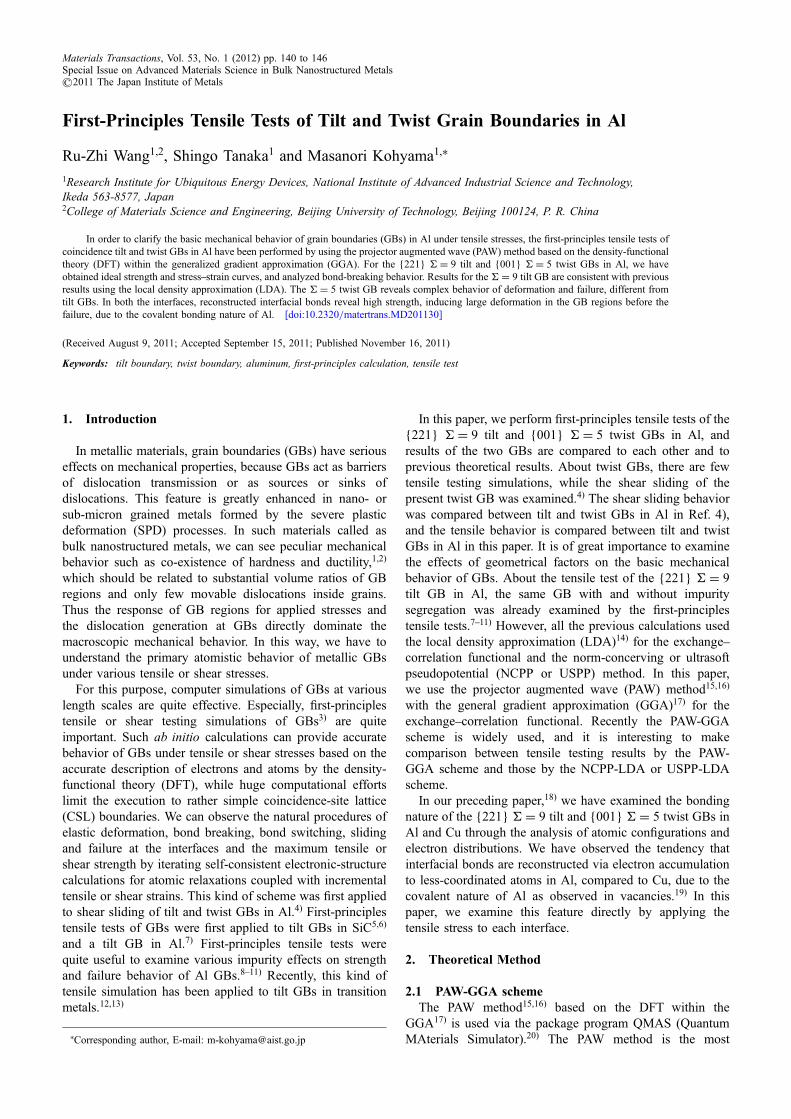
3.2 The {001} = 5 twist GB in AlFigure 4 shows the energystrain and stressstrain curves
of the {001} = 5 twist GB in Al, which show quitedifferent features from those of the = 9 tilt GB. In theenergystrain curve in Fig. 4(a), the total energy monotoni-cally increases for the strain without any energy decreaseeven after the failure. The stressstrain curves in Fig. 4(b)also reveal peculiar features in contrast to the present tilt GBand other tilt GBs in SiC and transition metals.57,13) Theincrease of the tensile stress normal to the interface, ·33,shows two stages until the maximum stress of 8.87GPa at24%, and the decrease of the stress normal to the interfacealso shows three stages after the failure. The curves for thestresses parallel to the interface, ·11 and ·22, show a similarshape with a smaller maximum value of 6.57GPa at 24%.Note that the two stress components parallel to the interfaceare identical by the symmetry. It can be said that the presenttwist GB is a little stronger than the present tilt GB.
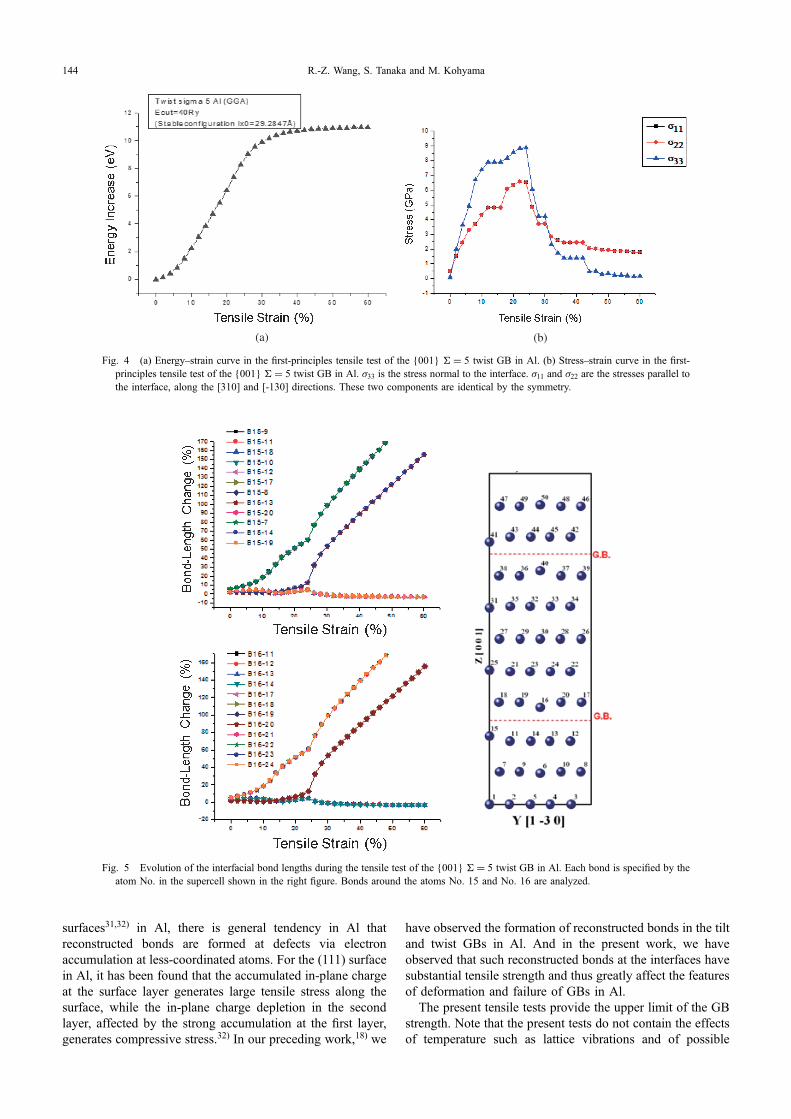
The complicated features of the stressstrain curves as wellas no energy decrease at the failure should be caused by thecomplicated deformation and failure procedure of the presenttwist GB as analyzed below. Figures 5 and 6 show theevolution of bond lengths and that of charge-density iso-surfaces, respectively, during the tensile test. We can seepeculiar behaviors of the atoms of No. 15 and No. 16 and theother interface atoms for the lower interface in the supercell,for example. In the early stage of the tensile test, especiallyafter the strain of 10%, the interlayer distance between thefirst layer, consisting of the atoms from No. 11 to No. 15,and the second layer, consisting of the atoms from No. 6 toNo. 10, begins to be increased in the lower crystal. Similarincrease occurs between the first layer of the atoms fromNo. 16 to No. 20 and the second layer of the atoms fromNo. 21 to No. 25 in the upper crystal. See the increases of thebonds No. 15No. 7 and No. 16No. 24, for example, inFig. 5. This means that the interface itself is rather strong,and thus the back inter-layers in both the crystals are mainlystretched in the early stage.
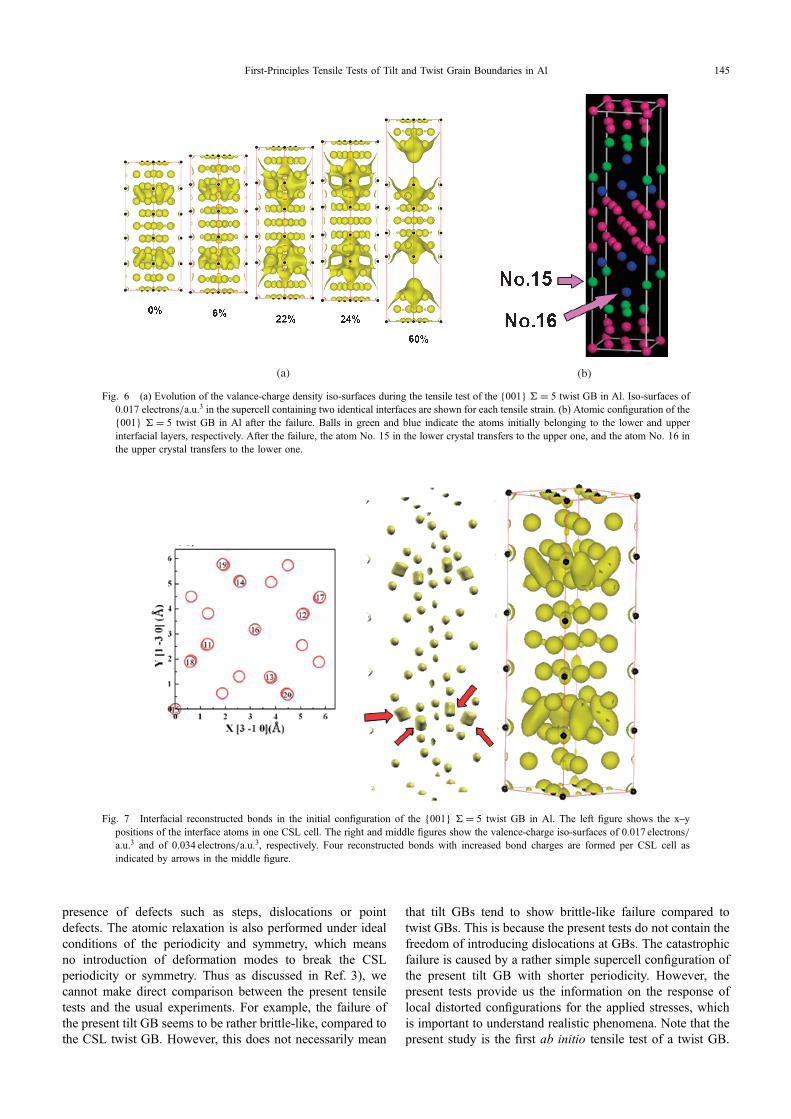
Figure 7 shows the presence of the interfacial recon-structed bonds with charge accumulation in the initialconfiguration, strengthening the present interface greatly.Four pairs of interfacial atoms, No. 11No. 18, No. 12No. 17, No. 13No. 20 and No. 14No. 19, per CSL cellconstitute the reconstructed bonds, and each atom has tenneighbors. Note that the atoms No. 15 and No. 16 are locatedat special symmetric sites with twelve neighbors as usualbulk atoms.
Then at the strain of 24% in the tensile test, on the otherhand, the interface starts to be broken, instead of the backinter-layers on both sides, while the atoms No. 15 and No. 16transfer to the other crystal at the interface, respectively.In Fig. 5, the in-plane bond distances of No. 15No. 11,No. 15No. 12, No. 15No. 13 and No. 15No. 14 on theinterface {001} layer are suddenly increased after the strainof 24%, and similarly the in-plane bond distances of No. 16No. 17, No. 16No. 18, No. 16No. 19 and No. 16No. 20are increased, which mean that the atoms No. 15 and No. 16move to a different grain, respectively, as clearly shown inFig. 6(b). Thus the cleavage surfaces are not flat, but roughatomically. These complex behaviors of the interface atomsare the reason why the stressstrain curves have peculiarshapes and the energy is not decreased at the failure.
R.-Z. Wang, S. Tanaka and M. Kohyama142

4. Discussion and Summary
It is interesting that the tilt and twist GBs reveal quitedifferent behaviors of deformation and failure. In the tilt GB,the failure initiates from the interface regions with relativelysmall electron density, other than the reconstructed bonds,while the reconstructed bonds sustain the GB strength in theearly stage of the tensile test. After the extension of theweakly bonded interface regions, the reconstructed bondscannot sustain the concentrated stress, and then the failureoccurs. For the twist GB, the interfacial reconstructed bondsare formed rather uniformly, and the back inter-layers insteadof the interface itself are stretched initially. The atoms in somesymmetric sites as No. 15 and No. 16, not belonging to thereconstructed bonds, suffer from the weakening of the backbonds toward the bulk side, due to the stretching of the backinter-layers. And then the atoms No. 15 and No. 16 transferto the other crystal at the interface, respectively, associatedwith the interface break, resulting in atomically roughcleavage surfaces. The two-dimensional wider interface areaof the CSL cell for the twist GB, in contrast to the tilt GB withrather narrow or short-period interface area of the CSL cell,should be also involved in the present phenomenon.
Of course, the present features of deformation and failurefor both the tilt and twist GBs in Al are originated from theformation of strong reconstructed bonds at the interface, dueto the covalent nature of Al. As observed in vacancies19) and
(a)
(b)
Fig. 1 (a) Energystrain curve in the first-principles tensile test of the{221} = 9 tilt GB in Al. (b) Stressstrain curve in the first-principlestensile test of the {221} = 9 tilt GB in Al. ·11 is the stress normal to theinterface. ·22 and ·33 are the stresses parallel to the interface, along the[-114] direction and along the [110] direction, respectively.
Fig. 2 Evolution of the atomic structure and charge density distributionduring the tensile test of the {221} = 9 tilt GB in Al. Arrows indicatethe interfacial reconstructed bonds with charge accumulation. One super-cell containing two identical interfaces is shown for each tensile strain.
Fig. 3 Evolution of the interfacial bond lengths during the tensile test ofthe {221} = 9 tilt GB in Al. Each bond is specified by the atom No. inthe supercell shown in the top figure, where red and blue balls indicateatoms with different heights along the [011] axis.
First-Principles Tensile Tests of Tilt and Twist Grain Boundaries in Al 143
surfaces31,32) in Al, there is general tendency in Al thatreconstructed bonds are formed at defects via electronaccumulation at less-coordinated atoms. For the (111) surfacein Al, it has been found that the accumulated in-plane chargeat the surface layer generates large tensile stress along thesurface, while the in-plane charge depletion in the secondlayer, affected by the strong accumulation at the first layer,generates compressive stress.32) In our preceding work,18) we
have observed the formation of reconstructed bonds in the tiltand twist GBs in Al. And in the present work, we haveobserved that such reconstructed bonds at the interfaces havesubstantial tensile strength and thus greatly affect the featuresof deformation and failure of GBs in Al.
The present tensile tests provide the upper limit of the GBstrength. Note that the present tests do not contain the effectsof temperature such as lattice vibrations and of possible
Fig. 5 Evolution of the interfacial bond lengths during the tensile test of the {001} = 5 twist GB in Al. Each bond is specified by theatom No. in the supercell shown in the right figure. Bonds around the atoms No. 15 and No. 16 are analyzed.
(a) (b)
Fig. 4 (a) Energystrain curve in the first-principles tensile test of the {001} = 5 twist GB in Al. (b) Stressstrain curve in the first-principles tensile test of the {001} = 5 twist GB in Al. ·33 is the stress normal to the interface. ·11 and ·22 are the stresses parallel tothe interface, along the [310] and [-130] directions. These two components are identical by the symmetry.
R.-Z. Wang, S. Tanaka and M. Kohyama144
presence of defects such as steps, dislocations or pointdefects. The atomic relaxation is also performed under idealconditions of the periodicity and symmetry, which meansno introduction of deformation modes to break the CSLperiodicity or symmetry. Thus as discussed in Ref. 3), wecannot make direct comparison between the present tensiletests and the usual experiments. For example, the failure ofthe present tilt GB seems to be rather brittle-like, compared tothe CSL twist GB. However, this does not necessarily mean
that tilt GBs tend to show brittle-like failure compared totwist GBs. This is because the present tests do not contain thefreedom of introducing dislocations at GBs. The catastrophicfailure is caused by a rather simple supercell configuration ofthe present tilt GB with shorter periodicity. However, thepresent tests provide us the information on the response oflocal distorted configurations for the applied stresses, whichis important to understand realistic phenomena. Note that thepresent study is the first ab initio tensile test of a twist GB.
(a) (b)
Fig. 6 (a) Evolution of the valance-charge density iso-surfaces during the tensile test of the {001} = 5 twist GB in Al. Iso-surfaces of0.017 electrons/a.u.3 in the supercell containing two identical interfaces are shown for each tensile strain. (b) Atomic configuration of the{001} = 5 twist GB in Al after the failure. Balls in green and blue indicate the atoms initially belonging to the lower and upperinterfacial layers, respectively. After the failure, the atom No. 15 in the lower crystal transfers to the upper one, and the atom No. 16 inthe upper crystal transfers to the lower one.
Fig. 7 Interfacial reconstructed bonds in the initial configuration of the {001} = 5 twist GB in Al. The left figure shows the xypositions of the interface atoms in one CSL cell. The right and middle figures show the valence-charge iso-surfaces of 0.017 electrons/a.u.3 and of 0.034 electrons/a.u.3, respectively. Four reconstructed bonds with increased bond charges are formed per CSL cell asindicated by arrows in the middle figure.
First-Principles Tensile Tests of Tilt and Twist Grain Boundaries in Al 145

As the next step, it is of great importance to deal withimpurity or defect effects on the tensile strength and failure oftwist GBs in Al.
In summary, we have performed the first-principles tensiletests of the {221} = 9 tilt and {001} = 5 twist GBs astypical coincidence tilt and twist GBs in Al. We haveobtained ideal strength and stressstrain curves, and analyzedthe bond-breaking behavior. The results for the = 9 tilt GBare consistent with previous LDA results. For the = 5 twistGB, the procedure of deformation and failure is rathercomplex, associated with the reconstructed interfacial bondsformed rather uniformly, resulting in peculiar stressstraincurves. In both the interfaces, the reconstructed interfacialbonds reveal high strength, inducing large deformation in theGB regions before the failure, due to the covalent bondingnature of Al.
Acknowledgement
The present study was supported by Grant-in-Aid forScientific Research on Priority Areas, “Giant StrainingProcess on Advanced Materials Containing Ultra-HighDensity Lattice Defects” (No. 18062007), and by Grant-in-Aid for Scientific Research on Innovative Area, “BulkNanostructured Metals” (No. 22102003). The authors thankProf. Zenji Horita, Prof. Nobuhiro Tsuji, Prof. Guang-HongLu, Prof. Masato Yoshiya and Dr. Tokuteru Uesugi forfruitful discussion. The authors also thank Dr. ShojiIshibashi, Dr. Tomoyuki Tamura and Dr. Yoshinori Shiiharafor helpful discussion on theoretical schemes.
REFERENCES
1) Z. Horita, K. Ohashi, T. Fujita, K. Kaneko and T. G. Langdon: Adv.Mater. 17 (2005) 1599.
2) X. Huang, N. Hansen and N. Tsuji: Science 312 (2006) 249.3) S. Ogata, Y. Umeno and M. Kohyama: Modell. Simul. Mater. Sci. Eng.
17 (2009) 013001.
4) C. Molteni, N. Marzari, M. C. Payne and V. Heine: Phys. Rev. Lett. 79(1997) 869.
5) M. Kohyama: Phil. Mag. Lett. 79 (1999) 659.6) M. Kohyama: Phys. Rev. B 65 (2002) 184107.7) G.-H. Lu, S. Deng, T. Wang, M. Kohyama and R. Yamamoto: Phys.
Rev. B 69 (2004) 134106.8) G.-H. Lu, Y. Zhang, S. Deng, T. Wang, M. Kohyama, R. Yamamoto, F.
Liu, K. Horikawa and M. Kanno: Phys. Rev. B 73 (2006) 224115.9) Y. Zhang, G.-H. Lu, T. Wang, S. Deng, X. Shu, M. Kohyama and R.
Yamamoto: J. Phys. Condens. Matter 18 (2006) 5121.10) Y. Zhang, G.-H. Lu, X. Hu, T. Wang, M. Kohyama and R. Yamamoto:
J. Phys. Condens. Matter 19 (2007) 456225.11) Y. Zhang, G.-H. Lu, S. Deng, T. Wang, H. Xu, M. Kohyama and R.
Yamamoto: Phys. Rev. B 75 (2007) 174101.12) Z. X. Tian, J. X. Yan, W. Xiao and W. T. Geng: Phys. Rev. B 79 (2009)
144114.13) M. Yuasa and M. Mabuchi: Phys. Rev. B 82 (2010) 094108.14) J. P. Perdew and A. Zunger: Phys. Rev. B 23 (1981) 5048.15) P. E. Blöchl: Phys. Rev. B 50 (1994) 17953.16) G. Kresse and D. Joubert: Phys. Rev. B 59 (1999) 1758.17) J. P. Perdew, K. Burke and M. Ernzerhof: Phys. Rev. Lett. 77 (1996)
3865.18) R. Z. Wang, M. Kohyama, S. Tanaka, T. Tamura and S. Ishibashi:
Mater. Trans. 50 (2009) 11.19) T. Uesugi, M. Kohyama and K. Higashi: Phys. Rev. B 68 (2003)
184103.20) S. Ishibashi, T. Tamura, S. Tanaka, M. Kohyama and K. Terakura:
http://qmas.jp21) H. J. Monkhorst and J. D. Pack: Phys. Rev. B 13 (1976) 5188.22) O. H. Nielsen and R. M. Martin: Phys. Rev. B 32 (1985) 3780.23) S. Ogata, J. Li and S. Yip: Science 298 (2002) 807.24) A. P. Sutton and R. W. Balluffi: Interfaces in Crystalline Materials,
(Oxford, 1995).25) D. A. Muller and M. J. Mills: Mater. Sci. Eng. A 260 (1999) 12.26) S. Ogata, H. Kitagawa, Y. Maegawa and K. Saitoh: Comp. Mater. Sci. 7
(1997) 271.27) W. Li and T. Wang: J. Phys. Condens. Matter 10 (1998) 9889.28) A. Dal Corso, A. Pasquarello, A. Baldereschi and R. Car: Phys. Rev. B
53 (1996) 1180.29) S. Kamran, K. Chen and L. Chen: Phys. Rev. B 79 (2009) 024106.30) D. M. Clatterbuck, C. R. Krenn, M. L. Cohen and J. W. Morris, Jr.:
Phys. Rev. Lett. 91 (2003) 135501.31) P. J. Feibelman: Phys. Rev. Lett. 65 (1990) 729.32) Y. Shiihara, M. Kohyama and S. Ishibashi: Phys. Rev. B 81 (2010)
075441.
R.-Z. Wang, S. Tanaka and M. Kohyama146